EP4567768A1 - Roaas runway alignment indications on airport moving map - Google Patents
Roaas runway alignment indications on airport moving map Download PDFInfo
- Publication number
- EP4567768A1 EP4567768A1 EP24217590.9A EP24217590A EP4567768A1 EP 4567768 A1 EP4567768 A1 EP 4567768A1 EP 24217590 A EP24217590 A EP 24217590A EP 4567768 A1 EP4567768 A1 EP 4567768A1
- Authority
- EP
- European Patent Office
- Prior art keywords
- runway
- arrival
- airport
- flight
- display
- Prior art date
- Legal status (The legal status is an assumption and is not a legal conclusion. Google has not performed a legal analysis and makes no representation as to the accuracy of the status listed.)
- Pending
Links
Images



Classifications
-
- G—PHYSICS
- G08—SIGNALLING
- G08G—TRAFFIC CONTROL SYSTEMS
- G08G5/00—Traffic control systems for aircraft
- G08G5/50—Navigation or guidance aids
- G08G5/54—Navigation or guidance aids for approach or landing
-
- B—PERFORMING OPERATIONS; TRANSPORTING
- B64—AIRCRAFT; AVIATION; COSMONAUTICS
- B64D—EQUIPMENT FOR FITTING IN OR TO AIRCRAFT; FLIGHT SUITS; PARACHUTES; ARRANGEMENT OR MOUNTING OF POWER PLANTS OR PROPULSION TRANSMISSIONS IN AIRCRAFT
- B64D45/00—Aircraft indicators or protectors not otherwise provided for
- B64D45/04—Landing aids; Safety measures to prevent collision with earth's surface
-
- G—PHYSICS
- G08—SIGNALLING
- G08G—TRAFFIC CONTROL SYSTEMS
- G08G5/00—Traffic control systems for aircraft
- G08G5/20—Arrangements for acquiring, generating, sharing or displaying traffic information
- G08G5/21—Arrangements for acquiring, generating, sharing or displaying traffic information located onboard the aircraft
-
- G—PHYSICS
- G08—SIGNALLING
- G08G—TRAFFIC CONTROL SYSTEMS
- G08G5/00—Traffic control systems for aircraft
- G08G5/20—Arrangements for acquiring, generating, sharing or displaying traffic information
- G08G5/23—Details of user output interfaces, e.g. information presented
-
- G—PHYSICS
- G08—SIGNALLING
- G08G—TRAFFIC CONTROL SYSTEMS
- G08G5/00—Traffic control systems for aircraft
- G08G5/70—Arrangements for monitoring traffic-related situations or conditions
- G08G5/74—Arrangements for monitoring traffic-related situations or conditions for monitoring terrain
Definitions
- the present invention generally relates to aircraft indicators, and more specifically to landing aids.
- ROAAS runway overrun awareness and alerting system
- the flight display comprises a memory maintaining a flight display system application
- the flight display comprises one or more processors configured to execute the flight display system application.
- the flight display system application causes the flight display to receive an arrival airport, a plurality of runways associated with the arrival airport, and a first arrival runway from a runway overrun awareness and alerting system.
- the arrival airport and the first arrival runway are from a flight plan.
- the flight display system application causes the flight display to display the arrival airport, the plurality of runways associated with the arrival airport, and the first arrival runway.
- the flight display system application causes the flight display to receive a selection of a second arrival runway.
- the first arrival runway and the second arrival runway are each one of the plurality of runways associated with the arrival airport.
- the flight display system application causes the flight display to transmit the second arrival runway to the runway overrun awareness and alerting system.
- the flight display system application causes the flight display to receive an airport moving map from an airport moving map application.
- the flight display system application causes the flight display to receive at least a first detection zone from the runway overrun awareness and alerting system.
- the first detection zone is associated with an aligned runway.
- the aligned runway is one of the plurality of runways associated with the arrival airport.
- the flight display system application causes the flight display to display the airport moving map with the first detection zone overlaid on the airport moving map.
- the first detection zone is displayed relative to the aligned runway.
- the second arrival runway is not the first arrival runway.
- the aligned runway is the first arrival runway.
- the aligned runway is the second arrival runway.
- the aligned runway is not the first arrival runway or the second arrival runway.
- the aligned runway comprises an approach threshold.
- the first detection zone is overlaid on the airport moving map starting from the approach threshold.
- the flight display system application causes the flight display to display a runway identifier associated with the aligned runway at a first end of the first detection zone which is opposed to a second end of the first detection zone which is disposed at the approach threshold.
- the first detection zone comprises a trapezoidal shape.
- the airport moving map is an overhead view of the arrival airport.
- the flight display system application causes the flight display to receive a plurality of detection zones and overlay the plurality of detection zones on the airport moving map.
- the plurality of detection zones are associated with at least the first arrival runway, the second arrival runway, and the aligned runway.
- the aircraft comprises a flight display.
- the flight display comprises a memory maintaining a flight display system application.
- the flight display comprises one or more processors configured to execute the flight display system application.
- the flight display system application causes the flight display to receive an arrival airport, a plurality of runways associated with the arrival airport, and a first arrival runway from a runway overrun awareness and alerting system.
- the arrival airport and the first arrival runway are from a flight plan.
- the flight display system application causes the flight display to display the arrival airport, the plurality of runways associated with the arrival airport, and the first arrival runway.
- the flight display system application causes the flight display to receive a selection of a second arrival runway.
- the aircraft comprises a second common computing module configured to execute a flight management system.
- the runway overrun awareness and alerting system is configured to receive the arrival airport from the flight plan via a flight management system.
- the aircraft comprises a navigation database.
- the runway overrun awareness and alerting system is configured to receive the plurality of runways associated with the arrival airport from the navigation database.
- the aircraft comprises a Synthetic Vision Module with Head Up Display configured to execute the airport moving map application.
- a letter following a reference numeral is intended to reference an embodiment of the feature or element that may be similar, but not necessarily identical, to a previously described element or feature bearing the same reference numeral (e.g., 1, 1a, 1b).
- reference numeral e.g. 1, 1a, 1b
- Such shorthand notations are used for purposes of convenience only and should not be construed to limit the disclosure in any way unless expressly stated to the contrary.
- any reference to “one embodiment” or “some embodiments” means that a particular element, feature, structure, or characteristic described in connection with the embodiment is included in at least one embodiment disclosed herein.
- the appearances of the phrase “in some embodiments” in various places in the specification are not necessarily all referring to the same embodiment, and embodiments may include one or more of the features expressly described or inherently present herein, or any combination or sub-combination of two or more such features, along with any other features which may not necessarily be expressly described or inherently present in the instant disclosure.
- Embodiments of the present disclosure are generally directed to a flight display.
- the flight display provides Runway Alignment Indications on an Airport Moving Map.
- the Runway Alignment Indications include Landing Runway Detection Zones on the Airport Moving Map for the crew-selected runway or the FMS arrival runway.
- the Landing Runway Detection Zones are geometrically sized, oriented, and placed in relation to the applicable landing runway approach thresholds.
- the cockpit 102 may include one or more flight displays 104 and one or more user interface (“UI") elements 106.
- the flight displays 104 may be implemented using any of a variety of display technologies, including CRT, LCD, organic LED, dot matrix display, and others.
- the flight displays 104 may be navigation (NAV) displays, primary flight displays, electronic flight bag displays, tablets, synthetic vision system displays, head up displays (HUDs) with or without a projector, and the like.
- the flight displays 104 may be used to provide information to the flight crew, thereby increasing visual range and enhancing decision-making abilities.
- One or more of the flight displays 104 may be configured to function as, for example, a primary flight display (PFD) used to display altitude, airspeed, vertical speed, and navigation and traffic collision avoidance system (TCAS) advisories.
- PFD primary flight display
- TCAS navigation and traffic collision avoidance system
- One or more of the flight displays 104 may also be configured to function as, for example, a multi-function display used to display navigation maps, weather radar, electronic charts, TCAS traffic, aircraft maintenance data and electronic checklists, manuals, and procedures.
- One or more of the flight displays 104 may also be configured to function as, for example, an engine indicating and crew-alerting system (EICAS) display used to display critical engine and system status data.
- EICAS engine indicating and crew-alerting system
- Other types and functions of the flight displays 104 are contemplated as well. According to various exemplary embodiments of the inventive concepts disclosed herein, at least one of the flight displays 104 may be configured to provide a rendered display from the systems and methods of the
- the flight displays 104 may provide an output based on data received from a system external to an aircraft, such as a ground-based weather radar system, satellite-based system, or from a system of another aircraft. In some embodiments, the flight displays 104 may provide an output from an onboard aircraft-based radar system, LIDAR system, infrared system or other system on an aircraft. For example, the flight displays 104 may include a weather display, a weather radar map, and a terrain display. In some embodiments, the flight displays 104 may provide an output based on a combination of data received from multiple external systems or from at least one external system and an onboard aircraft-based system. The flight displays 104 may include an electronic display or a synthetic vision system (SVS).
- SVS synthetic vision system
- the flight displays 104 may include a display configured to display a two-dimensional (2-D) image, a three-dimensional (3-D) perspective image of terrain and/or weather information, or a four-dimensional (4-D) display of weather information or forecast information.
- Other views of terrain and/or weather information may also be provided (e.g., plan view, horizontal view, vertical view).
- the views may include monochrome or color graphical representations of the terrain and/or weather information.
- Graphical representations of weather or terrain may include an indication of altitude of the weather or terrain or the altitude relative to an aircraft.
- the Ul elements 106 may include, for example, dials, switches, buttons, touch screens, keyboards, a mouse, joysticks, cursor control devices (CCDs) or other multi-function key pads certified for use with avionics systems.
- the Ul elements 106 may be configured to, for example, allow an aircraft crew member to interact with various avionics applications and perform functions such as data entry, manipulation of navigation maps, and moving among and selecting checklist items.
- the UI elements 106 may be used to adjust features of the flight displays 104, such as contrast, brightness, width, and length.
- the UI elements 106 may also (or alternatively) be used by an aircraft crew member to interface with or manipulate the displays of the flight displays 104.
- the UI elements 106 may be used by aircraft crew member to adjust the brightness, contrast, and information displayed on the flight displays 104.
- the UI elements 106 may additionally be used to acknowledge or dismiss an indicator provided by the flight displays 104.
- the UI elements 106 may be used to correct errors on the flight displays 104.
- Other UI elements 106 such as indicator lights, displays, display elements, and audio alerting devices, may be configured to warn of potentially threatening conditions such as severe weather, terrain, and obstacles, such as potential collisions with other aircraft.
- the aircraft 100 may include one or more components, such as, but not limited to, flight display 104, integrated processing cabinets (IPC 202), IPC 204, Synthetic Vision Module with Head Up Display (SVM-H 206), a common computing module (CCM 212), a Runway Overrun Awareness and Alerting System (ROAAS 214), navigation database 216 (NavDb), a common computing module (CCM 218), a flight management system (FMS 220), an Airport Moving Map Application (AMMA 208), and the like.
- components such as, but not limited to, flight display 104, integrated processing cabinets (IPC 202), IPC 204, Synthetic Vision Module with Head Up Display (SVM-H 206), a common computing module (CCM 212), a Runway Overrun Awareness and Alerting System (ROAAS 214), navigation database 216 (NavDb), a common computing module (CCM 218), a flight management system (FMS 220), an Airport Moving Map Application (AMMA 208), and the like.
- the aircraft 100 includes navigation database 216.
- the navigation database 216 may also be referred to as an airport / runway database.
- the navigation database 216 may be maintained in memory.
- the navigation database 216 may be maintained in memory of the IPC 204.
- the navigation database 216 may include various data used for navigating the aircraft 100.
- the navigation database 216 may include runways 224.
- the runways 224 may also be referred to as landing runways, arrival runways, and the like.
- the runways 224 may be associated with one or more airports.
- the runways 224 may be associated with an arrival airport 234 along with various other airports.
- the runways 224 may include various data, such as, but not limited to, an identifier 226, an approach threshold 228, and the like.
- Each of the runways 224 may include the identifier 226.
- the identifier 226 for the runways 224 may be based on the bearing of the runways 224.
- the bearing may refer to a compass bearing assigned to each runway.
- the bearing may be at 90 representing east, 180 representing south, 270 representing west, and 360 representing north.
- the bearing may be shortened to two digits and rounded (e.g., 9 representing east, 18 representing south, 27 representing west, and 36 representing north). In this instance, the bearing may range from 1 to 36, although this is not intended to be limiting.
- the identifier 226 for the runways 224 may also be based on the location of the runways 224 relative to adjacent of the runways. For example, adjacent runways may be referred to as bearing-left (e.g., bearing-L) and bearing-right (e.g., bearing-R), respectively.
- Each of the runways 224 may include the approach threshold 228.
- the approach threshold 228 may refer to a beginning of the runway 224.
- the approach threshold 228 may be stored as a coordinate (e.g., latitude and longitude).
- the identifier 226 and/or the approach threshold 228 may be printed on the runways 224.
- the identifier 226 and/or the approach threshold 228 may be physically printed on the runway to visually assist the pilot during landing.
- the identifier 226 may be printed as a set of block letters.
- the approach threshold 228 may be printed as threshold marking (e.g., a set of longitudinal stripes with a gap to indicate a centerline).
- the navigation database 216 may further include various data associated with the runways 224, such as, but not limited to, an approach end, a runway start, a runway end (e.g., a physical end of the runway), a stop way; a runway length, a displaced threshold (e.g., a runway displaced threshold), a condition, and the like.
- the navigation database 216 may also include published instrument approach procedures (lAPs), ground-based navigational aids, waypoints, holding patterns, airways, airports, heliports, instrument departure procedures, instrument arrival procedures, runways, precision approach aids, company routes, airport communications, localizer and airway markers, special use airspace, airport sector altitudes, enroute airways restrictions, enroute communications, preferred routes, controlled airspace, geographical references, arrival and/or departure flight planning, path point records, and GNSS Landing Systems.
- lAPs published instrument approach procedures
- ground-based navigational aids waypoints, holding patterns, airways, airports, heliports, instrument departure procedures, instrument arrival procedures, runways, precision approach aids
- company routes airport communications, localizer and airway markers, special use airspace, airport sector altitudes, enroute airways restrictions, enroute communications, preferred routes, controlled airspace, geographical references, arrival and/or departure flight planning, path point records, and GNSS Landing Systems.
- the navigation database 216 may be formatted according to one or more standards.
- the navigation database 216 may be compliant with one or more file format standards, such as, but not limited to, Aeronautical Radio, Incorporated ("ARINC") Specification-424.
- ARINC Aeronautical Radio, Incorporated
- the aircraft 100 includes CCM 218.
- the CCM 218 may be configured to run various software applications (e.g., a flight management system (FMS 220)) or computer code stored (e.g., maintained) in a non-transitory computer-readable medium.
- the CCM 218 may be configured to execute FMS 220.
- the CCM 218 may include a memory 201 maintaining the FMS 220 and one or more processors 203 configured to execute the FMS 220.
- the FMS 220 may be executed by one or more processors 203 of the CCM 218 to perform any of the various functions of the FMS 220.
- the FMS 220 may include a flight plan 232.
- the flight plan 232 may be maintained in a memory of the CCM 218 and/or FMS 220.
- the flight plan 232 may include various data, such as, but not limited to, an arrival airport 234 and/or an arrival runway 236.
- the arrival airport 234 may also be referred to as an FMS arrival airport.
- the arrival runway 236 may also be referred to as an FMS arrival runway or a first arrival runway.
- the arrival airport 234 may be one of the runways 224 associated with the arrival airport 234.
- the aircraft 100 may or may not follow the flight plan 232 to the arrival runway 236. During a landing maneuver, an actual arrival runway to which the aircraft 100 lands may differ from the arrival runway 236.
- the arrival runway 236 in the flight plan 232 may be updated in response to receiving a user input.
- a pilot e.g., captain, first officer
- manually changing the flight plan 232 during landing may be undesirable due to increasing a work-load of the pilot.
- the aircraft 100 includes a Synthetic Vision Module with Head Up Display (SVM-H 206).
- the SVM-H 206 may be configured to execute an Airport Moving Map Application (AMMA 208).
- the AMMA 208 may be configured to generate an airport moving map (AMM 238).
- the SVM-H 206 may include a memory 201 maintaining the AMMA 208 and one or more processors 203 configured to execute the AMMA 208.
- the AMMA 208 may be executed by one or more processors 203 of the SVM-H 206 to perform any of the various functions of the AMMA 208.
- the AMM 238 may be a computer-generated image.
- the AMM 238 may be a two-dimensional image.
- the AMM 238 may be an overhead view (e.g., directly overhead view) of the arrival airport 234.
- the AMM 238 may depict a location of the aircraft 100 relative to the arrival airport 234.
- the AMM may be an overhead view depicting the aircraft and a surrounding map.
- the AMM 238 may include a depiction of the aircraft 100 (e.g., a location (e.g., a current location) of the aircraft 100 (e.g., aircraft 100 performing an approach procedure) relative to the arrival airport 234), the runways 224 associated with the arrival airport 234, and the like.
- the AMM 238 may be a high-resolution map image which shows airport runways, taxiway images, and the like.
- the AMM 238 may be geo-referenced. In this regard, the AMM 238 may automatically scroll with movement of the aircraft 100 in real time.
- the AMM 238 may include a map range.
- the AMM 238 may provide a given level of detail within the map based on a selected map range. For example, the AMM 238 may automatically declutter or clutter map details based on the selected map range.
- the AMM 238 may allow for a variety of map ranges (e.g., the higher the map range, the more zoomed out the map is) to be used for operations during an approach procedure; for example, in some embodiments, the map range be between 1,000 feet and 6,000 feet (e.g., between 2,000 feet and 4,000 feet, such as 3,000 feet).
- NM nautical miles
- the AMMA 208 provides the AMM 238 to the FDSA 222 when the aircraft 100 is within a map range of the AMM 238.
- the map range may be less than two nautical miles.
- the AMMA 208 may determine that the aircraft 100 has reached a predetermined height (e.g., between 300 feet and 1,500 feet (e.g., between 600 feet and 1,000 feet, such as 750 feet)) above a ROAAS threshold for the runway during the approach procedure; and/or in response to the determination that the aircraft has reached the predetermined height above the runway, output the view of the AMM 238 as the graphical data.
- a predetermined height e.g., between 300 feet and 1,500 feet (e.g., between 600 feet and 1,000 feet, such as 750 feet)
- the aircraft 100 includes flight display 104.
- the flight display 104 may be configured to run various software applications (e.g., a flight display system application (FDSA 222)) or computer code stored (e.g., maintained) in a non-transitory computer-readable medium.
- the flight display 104 may be configured to execute a Flight Display System Application (FDSA 222).
- the FDSA 222 may be hosted within the flight display 104.
- the flight display 104 may include a memory 201 maintaining FDSA 222 and one or more processors 203 configured to execute the FDSA 222.
- the FDSA 222 may be executed by one or more processors 203 of the flight display 104 to perform any of the various functions of the FDSA 222.
- the AMMA 208 may provide the AMM 238 to the FDSA 222.
- the FDSA 222 may receive the AMM 238 from the FDSA 222.
- the FDSA 222 may display the AMM 238 on the flight display 104.
- the FDSA 222 is configured to cause the flight display 104 to display the AMM 238.
- the flight display 104 may output the view of the AMM 238 as graphical data.
- the at least one display may be configured to display the view of the AMM 238.
- the flight display 104 may be configured to generate a view of the AMM 238 depicting the aircraft 100 relative to the arrival runway 236, the arrival runway 240, and/or the aligned runway 242.
- the FDSA 222 may also draw an own aircraft symbol on the AMM 238 based on the geo-reference of the AMM 238 and the geo-reference of the aircraft 100.
- the own aircraft symbol may define where the aircraft 100 is in relation to the AMM 238.
- the aircraft 100 includes a common computing module (CCM 212).
- the CCM 212 may be configured to execute a Runway Overrun Awareness and Alerting System (ROAAS 214).
- the CCM 212 may include a memory 201 maintaining program instructions and one or more processors 203 configured to execute the program instructions.
- the ROAAS 214 may be executed by one or more processors 203 of the CCM 212 to perform any of the various functions of the ROAAS 214.
- the ROAAS 214 facilitates data flow from FMS 220 into FDSA 222 to populate a ROAAS Runway Control, accepts selections, and echoes the confirmation to the FDSA 222.
- the ROAAS 214 may have access to and/or determine any of the information from the navigation database 216.
- the ROAAS 214 may access the runways 224 associated with the arrival airport 234 from the navigation database 216.
- the FDSA 222 may be configured to receive the runways 224 associated with the arrival airport 234 from the ROAAS 214.
- the FDSA 222 may transmit the runways 224 associated with the arrival airport 234 to cause the flight display 104 to display said runways.
- the FDSA 222 may receive a selection of an arrival runway 240.
- the arrival runway 240 may also be referred to as a FDSA-selected arrival runway, crew-selected arrival runway, an intended landing runway, a second arrival runway, and the like.
- the arrival runway 240 may be one of the runways 224 associated with the arrival airport 234 which are displayed on the flight display 104.
- the arrival runway 240 may or may not be the arrival runway 236.
- the FDSA 222 thus enables the pilots to change the arrival runway 240 from the arrival runway 236 maintained in the flight plan 232 based on the current conditions of the flight.
- the FDSA 222 may transmit the arrival runway 240 to the ROAAS 214.
- the ROAAS 214 may include detection zones 230.
- Each of the runways 224 may be associated with one of the detection zones 230.
- the detection zones 230 may also be referred to as a landing zone, an approach zone, a landing runway detection zone, and the like.
- the detection zones 230 may start from the approach threshold 228.
- the detection zones 230 may be centered on the centerline of the runway 224.
- the detection zones 230 may extend from the approach threshold 228 for a given distance.
- the detection zones 230 may be a geometric shape.
- the detection zones 230 may include a trapezoidal shape.
- the trapezoidal shape may include a first end and a second end. The first end of the trapezoid may be widest. The second end of the trapezoid may be narrowest and disposed at the approach threshold 228.
- the ROAAS 214 may determine an aligned runway 242.
- the aligned runway 242 may also be referred to as a ROAAS-selected landing runway.
- the aligned runway 242 may be one of the runways 224 associated with the arrival airport 234.
- the aligned runway 242 may be the arrival runway 236, the arrival runway 240, or another of the runways 224 associated with the arrival airport 234.
- the aligned runway 342 may or may not be the arrival runway 236 or the arrival runway 340.
- the ROAAS 214 may determine the aircraft 100 is aligned to the aligned runway 242 based on a heading of the aircraft 100.
- the ROAAS 214 may determine the aligned runway 242 as part of one or more alerting algorithms. In embodiments, the ROAAS 214 may determine whether the aircraft 100 is aligned for landing on each of the runways 224 associated with the arrival airport 234. Below 750 ft, ROAAS 214 starts checking if the aircraft 100 is headed in the direction toward the runways 224 associated with the arrival airport 234 and within the bounds of the detection zones 230. The ROAAS 214 may output one or more flags indicating whether the aircraft 100 is landing on the arrival runway 236, arrival runway 240, another of the runways 224 associated with the arrival airport 234, or an unknown surface.
- the ROAAS 214 may mark one of the runways 224 associated with the arrival airport 234 as the aligned runway 242 when all of the following are true: the aircraft 100 height is at or below 750 ft; the ROAAS 214 State is Ready or In Air; the aircraft 100 is oriented in the direction of the runway; and any of the following is true: the aircraft 100 is inside of the detection zone 230 or the projected flight path of the aircraft 100 intersects the extended runway threshold in the direction of the runway heading.
- a ROAAS state is ready or in air may refers to a state machine within the ROAAS 214 used to determine when the ROAAS 214 is available to provide overrun alerts.
- Ready or in air may have to do with the position, heading, and track of the aircraft 100 in relation a centerline of the runways 224. Ready may mean the ROAAS 214 knows the aircraft 100 is in the vicinity of the arrival airport 234 and when the aircraft 100 is within range of the approach threshold 228.
- the ROAAS 214 may flag to the FDSA 222 which of the detection zones 230 is associated with the aligned runway 242.
- the flags output by the ROAAS 214 may indicate whether the aircraft 100 is landing on the 236, the arrival runway 240, another of the runways 224 associated with the arrival airport 234, or an unknown surface.
- the flags output by the ROAAS 214 may or may not be displayed to the flight crew.
- the ROAAS 214 flags for the aligned runway 242 may be transparent to the flight crew. This may result in confusion within the flight deck when the ROAAS 214 is indicating a ROAAS unavailable condition (no detected landing runway) or misleading alerting occurs (alerting based upon a different runway than what the crew was expecting). For example, these conditions are more prevalent when the arrival airport 234 contains several runways with the approach threshold within proximity to each other, when the crew is performing circle to land maneuvers or side step maneuvers.
- the detection zones 230 may overlap.
- the ROAAS 214 may be configured to determine, generate, and/or obtain runway overrun awareness and alerting system (ROAAS) data associated with an approach procedure being performed by the aircraft 100 toward one or more of the runways 224.
- the ROAAS 214 may be configured to determine, generate, and/or obtain runway overrun awareness and alerting system (ROAAS) data associated with an approach procedure being performed by the aircraft 100 toward any of the arrival runway 236, the arrival runway 240, and/or the aligned runway 242.
- the ROAAS 214 may provide overrun alerting for the aligned runway 242.
- the ROAAS provides runway overrun and alerting based on the aligned runway 242 because the aircraft 100 is likely to land on the aligned runway 242.
- the flight crew may see alerts on the flight display 104 for a runway overrun and change the energy state of the aircraft 100 to reduce the risk of overrunning the runway.
- the ROAAS 214 may determine the aligned runway 242 without requiring a pilot to update the arrival runway 236 or the arrival runway 240. However, the aligned runway 242 may be different than the arrival runway 236 and the arrival runway 240. Therefore, the pilot may be confused as to which of the runways 224 the ROAAS 214 is providing alerting without further receiving information from the ROAAS 214.
- the ROAAS 214 may send the detection zones 230 associated with the arrival runway 236, the arrival runway 240, and/or the aligned runway 242 to the FDSA 222.
- the ROAAS 214 may send the latitude and longitude for the four corners of the detection zones 230.
- the FDSA 222 may receive the detection zones 230 associated with the arrival runway 236, the arrival runway 240, and/or the aligned runway 242 from the ROAAS 214.
- the flight display 104 may be configured to display the detection zones 230 associated with the arrival runway 236, the arrival runway 240, and/or the aligned runway 242.
- the FDSA 222 may cause the flight display 104 to display the detection zones 230 associated with the arrival runway 236, the arrival runway 240, and/or the aligned runway 242 on the AMM 238.
- the detection zones 230 may be displayed relative to the associated arrival runway 236, the arrival runway 240, and/or the aligned runway 242.
- the detection zones 230 may be geometrically sized, oriented, and placed in relation to the approach thresholds 228. For example, the detection zones 230 may be displayed starting from the approach threshold 228 of the associated arrival runway 236, the arrival runway 240, and/or the aligned runway 242.
- the detection zones 230 may be provided as a trapezoid shape on the AMM 238.
- the trapezoid shapes may be overlaid or imposed on the AMM 238.
- the detection zones 230 may provide a visual indication on the AMM 238 which runway the aircraft 100 is aligned to provide the crew with a better situation awareness. It is contemplated that displaying the detection zones 230 may be helpful in airports with runways which are aligned in parallel and are adjacent. Crew situational awareness may be enhanced with the detection zones 230 displayed in relation to the runways 224 and aircraft symbol placed on the AMM 238.
- the FDSA 222 may cause the flight display 104 to overlay one or more of the detection zones 230 on the AMM 238.
- the flight display 104 may overlay the detection zones 230 on the AMM 238 for each of the arrival runway 236, the arrival runway 240, and/or the aligned runway 242.
- the flight display 104 may display one of the detection zones 230 for the arrival runway 236, one of the detection zones 230 for the arrival runway 240, and/or one of the detection zones 230 for the aligned runway 242.
- the flight display 104 may receive at least a first detection zone from the ROAAS 214, where the first detection zone is associated with the aligned runway 242, and display the AMM 238 with the first detection zone overlaid on the AMM 238, where the first detection zone is displayed relative to the aligned runway 242.
- the flight display may receive a plurality of the detection zones 230 and overlay the plurality of detection zones 230 on the AMM 238, where the plurality of the detection zones 230 are associated with at least the arrival runway 236, the arrival runway 240, and/or the aligned runway 242.
- the FDSA 222 may highlight the detection zone 230 associated with the aligned runway 242. For example, an emphasized border may be placed around the detection zone 230 associated with the aligned runway 242 to visually identify which runway the ROAAS is performing its alerting algorithms. No border may be placed around the detection zones 230 if the aircraft 100 is not aligned.
- the detection zones 230 are displayed with one or more translucent color shades.
- the translucent color shades of the detection zones 230 provide quick identification for which type of detection zone is depicted on the AMM 238.
- the detection zone 230 associated with the arrival runway 236 may be displayed with a magenta color.
- the detection zone 230 associated with the arrival runway 240 may be displayed with a cyan color.
- the own ship symbol of the aircraft 100 may be colored with magenta or cyan when aligned with the corresponding detection zone.
- the runway identifier 226 are displayed at the base of the detection zone 230.
- the runway identifier may help the flight crew relate the detection zone 230 to the associated runway 224.
- the runway identifier 226 are displayed at a first end of the detection zone 230 which is opposed to a second end of the detection zone 230 disposed at the approach threshold 228.
- the aircraft 100 may include a digital switch module (DSM 210).
- the DSM 210 may include Avionics Full Duplex Switched Ethernet (AFDX). AFDX communication between the systems is managed through the DSM 210 which resides in the IPC 204.
- the DSM 210 may be configured to route data (e.g., graphical data and/or ROAAS data).
- the DSM 210 may route various data between the AMMA 208, the FMS 220, the ROAAS 214, and the FDSA 222.
- the DSM 210 may provide the AMM 238 from the AMMA 208 to the FDSA 222.
- the DSM 210 may provide the detection zones 230 from the ROAAS 214 to the FDSA 222.
- the SVM-H 206, the AMMA 208, the DSM 210, the CCM 212, the ROAAS 214, the navigation database 216, the CCM 218, and/or the FMS 220 may be contained in one or more integrated processing cabinets (IPCs).
- the IPC 202 include the SVM-H 206 and the AMMA 208.
- the IPC 204 includes the DSM 210, the CCM 212, the ROAAS 214, the navigation database 216, the CCM 218, and/or the FMS 220.
- the AMMA 208 may be hosted on the SVM-H 206 which may resides in IPC 202.
- the ROAAS 214 may be hosted on the CCM 212 which resides in IPC 204.
- the FMS 220 may be hosted on CCM 218 which resides in IPC 204.
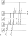
- a timing diagram of a method 300 is described, in accordance with one or more embodiments of the present disclosure.
- the method 300 shows the data flow between the various applications of the aircraft 100.
- the embodiments and the enabling technology described previously herein in the context of the aircraft 100 should be interpreted to extend to the method 300.
- the method 300 may be implemented by the aircraft 100.
- the FMS 220 may enter the arrival airport 234 in the flight plan 232.
- the FMS 220 may enter the arrival airport 234 in the flight plan 232 when setting up the flight plan 232 in the FMS 220.
- the arrival airport 234 may be entered during pre-flight by a pilot.
- the FMS 220 may receive the arrival airport 234 via the UI elements 106, or the like.
- the FMS 220 may receive the arrival airport 234 on one or more user interface pages of the FMS 220.
- the FMS 220 may include a dialogue box to define the arrival airport 234.
- the FMS 220 may transmit the arrival airport 234 to the ROAAS 214.
- ROAAS 214 receives the arrival airport 234 from the flight plan 232 via the FMS 220.
- the ROAAS 214 may receive the runways 224 associated with the arrival airport 234 from the navigation database 216. For example, the ROAAS 214 may query the navigation database 216 for the runways 224 associated with the arrival airport 234. The ROAAS 214 may or may not retrieve runways associated with other airports in the navigation database 216.
- the ROAAS 214 may transmit the arrival airport 234 and the runways 224 associated with the arrival airport 234 to the FDSA 222.
- the runways 224 associated with the arrival airport 234 may include a list of all runways, lengths, and the like.
- the FDSA 222 may use the arrival airport 234 to populate a Runway Control dialogue box.
- the FMS 220 may enter the arrival runway 236 in the flight plan 232.
- the FMS 220 may enter the arrival runway 236 in the flight plan 232 when setting up the flight plan 232 or after the flight plan 232 is set up.
- the arrival runway 236 may be entered during pre-flight or during flight.
- the FMS 220 may enter the arrival runway 236 in the flight plan 232 concurrent with or after entering the arrival airport 234 in the flight plan 232.
- the FMS 220 may receive the arrival runway 236 via the UI elements 106, or the like.
- the FMS 220 may receive the arrival runway 236 on one or more user interface pages of the FMS 220.
- the FMS 220 may include a dialogue box to define the arrival runway 236.
- the FMS 220 may transmit the arrival runway 236 to the ROAAS 214.
- ROAAS 214 may receive the arrival runway 236 from the flight plan 232 via the FMS 220.
- the FMS 220 may provide flight plan information of the intended landing runway.
- the ROAAS 214 may transmit the arrival runway 236 to the FDSA 222.
- the FDSA 222 may cause the flight display 104 to receive the arrival runway 236 from the ROAAS 214.
- the FDSA 222 may cause the flight display 104 to display the arrival airport 234, the arrival runway 236, and the runways 224 associated with the arrival airport 234.
- the flight display 104 may display a Runway Control dialogue box.
- the FDSA 222 may use both the arrival airport 234, the arrival runway 236, and the runways 224 associated with the arrival airport 234 to populate the Runway Control dialogue box.
- the FDSA 222 may cause the flight display 104 to display the Runway Control dialogue box, including the runways 224 associated with the arrival airport 234.
- the runways 224 associated with the arrival airport 234 may be depicted as a drop-down box on the Runway Control dialogue box.
- a pilot may then select any of the runways 224 associated with the arrival airport 234 using the Runway Control dialogue box.
- the arrival runway 236 may be preloaded as an initial entry in the drop-down box.
- the runways 224 associated with the arrival airport 234 may be the other options of the drop-down box.
- the FDSA 222 may cause the flight display 104 to receive a selection of the arrival runway 240.
- the arrival runway 240 is one of the runways 224 associated with the arrival airport 234.
- the arrival runway 240 may or may not be the arrival runway 236 in the flight plan 232.
- the FDSA 222 may receive the selection of the arrival runway 240 from the Runway Control dialogue box. For example, the pilot may select the arrival runway 240 via the Runway Control dialogue box.
- the FDSA 222 allows the pilot to select arrival runway 240 which are different than the arrival runway 236 the flight plan 232.
- the FDSA 222 may also cause the flight display 104 to receive various data associated with the arrival runway 240.
- the FDSA may receive one or more conditions, offsets, Localizer directional aides (LDA), and the like.
- LDA Localizer directional aides
- the FDSA 222 may cause the flight display 104 to transmit the arrival runway 240 to the ROAAS 214.
- the FDSA may also transmit the various data associated with the arrival runway 240, such as, but not limited to, the conditions, offsets, LDA, and the like.
- the ROAAS 214 receives the arrival runway 240 and the data associated with the arrival runway 240.
- the ROAAS 214 may transmit an acknowledgement to the FDSA 222 indicating the arrival runway 240 and the LDA is accepted.
- the AMMA 208 may transmit the AMM 238 to the FDSA 222.
- the FDSA 222 may cause the flight display 104 to receive the AMM 238 from the AMMA 208.
- the ROAAS 214 may transmit the detection zones 230 associated with the arrival runway 236, the arrival runway 240, and/or the aligned runway 242 to the FDSA 222.
- the ROAAS 214 may transmit the coordinates associated with the corners of the detection zones 230 to the FDSA 222.
- the FDSA 222 may cause the flight display 104 to receive at least a first detection zone.
- the first detection zone is associated with the aligned runway 242.
- the aligned runway 242 may be one of the arrival runway 236 or the arrival runway 240.
- the FDSA 222 may cause the flight display 104 to receive a second detection zone which is associated with the arrival runway 236 or the arrival runway 240.
- the FDSA 222 may cause the flight display 104 to display the AMM 238 with the detection zones 230 overlaid on the AMM 238.
- the FDSA 222 may superimpose the detection zones 230 over the AMM 238.
- the AMM 238 depicts the arrival runway 236, a first approach threshold 228a associated with the arrival runway 236, a first detection zone 230a associated with the arrival runway 236, the arrival runway 240, a second approach threshold 228b associated with the arrival runway 240, a second detection zone 230b associated with the arrival runway 240, and an own aircraft symbol 402 associated with a position of the aircraft 100.
- the first detection zone 230a is placed at the first approach threshold 228a.
- the second detection zone 230b is placed at the second approach threshold 228b.
- the runway identifiers 226 (e.g., runway 24, runway 19) of the detection zones 230 are placed at the base of the first detection zone 230a and the second detection zone 230b.
- the projected track of the aircraft 100 intersects with the second approach threshold 228b associated with the arrival runway 240.
- the aligned runway 242 is the arrival runway 240.
- the arrival runway 240 is thus highlighted with an outline.
- steps may be carried out in any desired order and two or more of the steps may be carried out simultaneously with one another.
- Two or more of the steps disclosed herein may be combined in a single step, and in some embodiments, one or more of the steps may be carried out as two or more sub-steps. Further, other steps or sub-steps may be carried in addition to, or as substitutes to one or more of the steps disclosed herein.
- a processor may include any processing unit known in the art.
- the processor may include a multi-core processor, a single-core processor, a reconfigurable logic device (e.g., FPGAs), a digital signal processor (DSP), a special purpose logic device (e.g., ASICs)), or other integrated formats.
- a reconfigurable logic device e.g., FPGAs
- DSP digital signal processor
- ASICs special purpose logic device
- the processor(s) may include any microprocessor-type device configured to execute software algorithms and/or instructions.
- processor may be broadly defined to encompass any device having one or more processing elements, which execute program instructions from memory, from firmware, or by hardware implemented functions. It should be recognized that the steps described throughout the present disclosure may be carried out by the processors.
- a memory may include any storage medium known in the art.
- the storage medium may include a non-transitory memory medium.
- the non-transitory memory medium may include, but is not limited to, a read-only memory (ROM), a random-access memory (RAM), a magnetic or optical memory device (e.g., disk), a solid-state drive and the like.
- memory may be housed in a common controller housing with the one or more processor(s).
- the memory and the processor may be housed in a processing unit, a desktop computer, or the like.
- the memory may be located remotely with respect to the physical location of the processor.
- the memory maintains program instructions for causing the processor(s) to carry out the various steps described through the present disclosure.
- inventive concepts disclosed herein are well adapted to carry out the objects and to attain the advantages mentioned herein as well as those inherent in the inventive concepts disclosed herein. While presently preferred embodiments of the inventive concepts disclosed herein have been described for purposes of this disclosure, it will be understood that numerous changes may be made which will readily suggest themselves to those skilled in the art and which are accomplished within the broad scope and coverage of the inventive concepts disclosed and claimed herein.
Landscapes
- Engineering & Computer Science (AREA)
- Aviation & Aerospace Engineering (AREA)
- Physics & Mathematics (AREA)
- General Physics & Mathematics (AREA)
- Traffic Control Systems (AREA)
Abstract
A flight display (104) provides Runway Alignment Indications on an Airport Moving Map (238). The Runway Alignment Indications include Landing Runway Detection Zones on the Airport Moving Map for the crew-selected runway or the FMS arrival runway. The Landing Runway Detection Zones are geometrically sized, oriented, and placed in relation to the applicable landing runway approach thresholds.
Description
- The present invention generally relates to aircraft indicators, and more specifically to landing aids.
- Currently, flight displays lack of means of visualizing runway overrun awareness and alerting system (ROAAS) determined information during an approach procedure. It is difficult for flight crew to visualize where ROAAS alerts are anticipated to occur along the intended landing runway. Therefore, it would be advantageous to provide a device, system, and method that cures the shortcomings described above.
- A flight display is described, in accordance with one or more embodiments of the present disclosure. The flight display comprises a memory maintaining a flight display system application The flight display comprises one or more processors configured to execute the flight display system application. The flight display system application causes the flight display to receive an arrival airport, a plurality of runways associated with the arrival airport, and a first arrival runway from a runway overrun awareness and alerting system. The arrival airport and the first arrival runway are from a flight plan. The flight display system application causes the flight display to display the arrival airport, the plurality of runways associated with the arrival airport, and the first arrival runway. The flight display system application causes the flight display to receive a selection of a second arrival runway. The first arrival runway and the second arrival runway are each one of the plurality of runways associated with the arrival airport. The flight display system application causes the flight display to transmit the second arrival runway to the runway overrun awareness and alerting system. The flight display system application causes the flight display to receive an airport moving map from an airport moving map application. The flight display system application causes the flight display to receive at least a first detection zone from the runway overrun awareness and alerting system. The first detection zone is associated with an aligned runway. The aligned runway is one of the plurality of runways associated with the arrival airport. The flight display system application causes the flight display to display the airport moving map with the first detection zone overlaid on the airport moving map. The first detection zone is displayed relative to the aligned runway.
- In some embodiments, the second arrival runway is not the first arrival runway.
- In some embodiments, the aligned runway is the first arrival runway.
- In some embodiments, the aligned runway is the second arrival runway.
- In some embodiments, the aligned runway is not the first arrival runway or the second arrival runway.
- In some embodiments, the aligned runway comprises an approach threshold. The first detection zone is overlaid on the airport moving map starting from the approach threshold.
- In some embodiments, the flight display system application causes the flight display to display a runway identifier associated with the aligned runway at a first end of the first detection zone which is opposed to a second end of the first detection zone which is disposed at the approach threshold.
- In some embodiments, the first detection zone comprises a trapezoidal shape.
- In some embodiments, the airport moving map is an overhead view of the arrival airport.
- In some embodiments, the flight display system application causes the flight display to receive a plurality of detection zones and overlay the plurality of detection zones on the airport moving map.
- In some embodiments, the plurality of detection zones are associated with at least the first arrival runway, the second arrival runway, and the aligned runway.
- An aircraft is described, in accordance with one or more embodiments of the present disclosure. The aircraft comprises a flight display. The flight display comprises a memory maintaining a flight display system application. The flight display comprises one or more processors configured to execute the flight display system application. The flight display system application causes the flight display to receive an arrival airport, a plurality of runways associated with the arrival airport, and a first arrival runway from a runway overrun awareness and alerting system. The arrival airport and the first arrival runway are from a flight plan. The flight display system application causes the flight display to display the arrival airport, the plurality of runways associated with the arrival airport, and the first arrival runway. The flight display system application causes the flight display to receive a selection of a second arrival runway. The first arrival runway and the second arrival runway are each one of the plurality of runways associated with the arrival airport. The flight display system application causes the flight display to transmit the second arrival runway to the runway overrun awareness and alerting system. The flight display system application causes the flight display to receive an airport moving map from an airport moving map application. The flight display system application causes the flight display to receive at least a first detection zone from the runway overrun awareness and alerting system. The first detection zone is associated with an aligned runway. The aligned runway is one of the plurality of runways associated with the arrival airport. The flight display system application causes the flight display to display the airport moving map with the first detection zone overlaid on the airport moving map. The first detection zone is displayed relative to the aligned runway. The aircraft comprises a common computing module configured to execute the runway overrun awareness and alerting system.
- In some embodiments, the aircraft comprises a second common computing module configured to execute a flight management system. The runway overrun awareness and alerting system is configured to receive the arrival airport from the flight plan via a flight management system.
- In some embodiments, the aircraft comprises a navigation database. The runway overrun awareness and alerting system is configured to receive the plurality of runways associated with the arrival airport from the navigation database.
- In some embodiments, the aircraft comprises a Synthetic Vision Module with Head Up Display configured to execute the airport moving map application.
- Implementations of the concepts disclosed herein may be better understood when consideration is given to the following detailed description thereof. Such description makes reference to the included drawings, which are not necessarily to scale, and in which some features may be exaggerated and some features may be omitted or may be represented schematically in the interest of clarity. Like reference numerals in the drawings may represent and refer to the same or similar element, feature, or function. In the drawings:
-
FIG. 1 depicts a schematic illustration of a cockpit of an aircraft, in accordance with one or more embodiments of the present disclosure. -
FIG. 2A depicts a block diagram of an aircraft, in accordance with one or more embodiments of the present disclosure. -
FIG. 2B depicts a block diagram of a flight display, Synthetic Vision Module with Head Up Display, and common computing modules, in accordance with one or more embodiments of the present disclosure. -
FIG. 3 depicts a timing diagram of a method, in accordance with one or more embodiments of the present disclosure. -
FIG. 4 depicts an exemplary airport moving map, in accordance with one or more embodiments of the present disclosure. - Before explaining one or more embodiments of the disclosure in detail, it is to be understood that the embodiments are not limited in their application to the details of construction and the arrangement of the components or steps or methodologies set forth in the following description or illustrated in the drawings. In the following detailed description of embodiments, numerous specific details are set forth in order to provide a more thorough understanding of the disclosure. However, it will be apparent to one of ordinary skill in the art having the benefit of the instant disclosure that the embodiments disclosed herein may be practiced without some of these specific details. In other instances, well-known features may not be described in detail to avoid unnecessarily complicating the instant disclosure.
- As used herein a letter following a reference numeral is intended to reference an embodiment of the feature or element that may be similar, but not necessarily identical, to a previously described element or feature bearing the same reference numeral (e.g., 1, 1a, 1b). Such shorthand notations are used for purposes of convenience only and should not be construed to limit the disclosure in any way unless expressly stated to the contrary.
- Further, unless expressly stated to the contrary, "or" refers to an inclusive or and not to an exclusive or. For example, a condition A or B is satisfied by any one of the following: A is true (or present) and B is false (or not present), A is false (or not present) and B is true (or present), and both A and B are true (or present).
- In addition, use of "a" or "an" may be employed to describe elements and components of embodiments disclosed herein. This is done merely for convenience and "a" and "an" are intended to include "one" or "at least one," and the singular also includes the plural unless it is obvious that it is meant otherwise.
- Finally, as used herein any reference to "one embodiment" or "some embodiments" means that a particular element, feature, structure, or characteristic described in connection with the embodiment is included in at least one embodiment disclosed herein. The appearances of the phrase "in some embodiments" in various places in the specification are not necessarily all referring to the same embodiment, and embodiments may include one or more of the features expressly described or inherently present herein, or any combination or sub-combination of two or more such features, along with any other features which may not necessarily be expressly described or inherently present in the instant disclosure.
- Reference will now be made in detail to the subject matter disclosed, which is illustrated in the accompanying drawings. Embodiments of the present disclosure are generally directed to a flight display. The flight display provides Runway Alignment Indications on an Airport Moving Map. The Runway Alignment Indications include Landing Runway Detection Zones on the Airport Moving Map for the crew-selected runway or the FMS arrival runway. The Landing Runway Detection Zones are geometrically sized, oriented, and placed in relation to the applicable landing runway approach thresholds.
- U.S. Patent Publication Number
US20050128129A1 , titled "Ground operations and imminent landing runway selection";U.S. Patent Application Number 18/233,087 , titled "System And Method To Display View Of Airport Moving Map Depicting Runway Overrun Awareness And Alerting System (ROAAS)-Based Indicators";U.S. Patent Application Number 18/233,072 , titled "System And Method To Generate And Display Runway Overrun Awareness And Alerting System (ROAAS) Image Depicting Current Runway Displaced Threshold Value And Current Landing Distance Available Value". - Referring to
FIG. 1 , a schematic illustration of acockpit 102 of anaircraft 100 is described, according to an exemplary embodiment of the inventive concepts disclosed herein. Thecockpit 102 may include one or more flight displays 104 and one or more user interface ("UI")elements 106. The flight displays 104 may be implemented using any of a variety of display technologies, including CRT, LCD, organic LED, dot matrix display, and others. The flight displays 104 may be navigation (NAV) displays, primary flight displays, electronic flight bag displays, tablets, synthetic vision system displays, head up displays (HUDs) with or without a projector, and the like. The flight displays 104 may be used to provide information to the flight crew, thereby increasing visual range and enhancing decision-making abilities. One or more of the flight displays 104 may be configured to function as, for example, a primary flight display (PFD) used to display altitude, airspeed, vertical speed, and navigation and traffic collision avoidance system (TCAS) advisories. One or more of the flight displays 104 may also be configured to function as, for example, a multi-function display used to display navigation maps, weather radar, electronic charts, TCAS traffic, aircraft maintenance data and electronic checklists, manuals, and procedures. One or more of the flight displays 104 may also be configured to function as, for example, an engine indicating and crew-alerting system (EICAS) display used to display critical engine and system status data. Other types and functions of the flight displays 104 are contemplated as well. According to various exemplary embodiments of the inventive concepts disclosed herein, at least one of the flight displays 104 may be configured to provide a rendered display from the systems and methods of the present disclosure. - In some embodiments, the flight displays 104 may provide an output based on data received from a system external to an aircraft, such as a ground-based weather radar system, satellite-based system, or from a system of another aircraft. In some embodiments, the flight displays 104 may provide an output from an onboard aircraft-based radar system, LIDAR system, infrared system or other system on an aircraft. For example, the flight displays 104 may include a weather display, a weather radar map, and a terrain display. In some embodiments, the flight displays 104 may provide an output based on a combination of data received from multiple external systems or from at least one external system and an onboard aircraft-based system. The flight displays 104 may include an electronic display or a synthetic vision system (SVS). For example, the flight displays 104 may include a display configured to display a two-dimensional (2-D) image, a three-dimensional (3-D) perspective image of terrain and/or weather information, or a four-dimensional (4-D) display of weather information or forecast information. Other views of terrain and/or weather information may also be provided (e.g., plan view, horizontal view, vertical view). The views may include monochrome or color graphical representations of the terrain and/or weather information. Graphical representations of weather or terrain may include an indication of altitude of the weather or terrain or the altitude relative to an aircraft.
- The
Ul elements 106 may include, for example, dials, switches, buttons, touch screens, keyboards, a mouse, joysticks, cursor control devices (CCDs) or other multi-function key pads certified for use with avionics systems. TheUl elements 106 may be configured to, for example, allow an aircraft crew member to interact with various avionics applications and perform functions such as data entry, manipulation of navigation maps, and moving among and selecting checklist items. For example, theUI elements 106 may be used to adjust features of the flight displays 104, such as contrast, brightness, width, and length. TheUI elements 106 may also (or alternatively) be used by an aircraft crew member to interface with or manipulate the displays of the flight displays 104. For example, theUI elements 106 may be used by aircraft crew member to adjust the brightness, contrast, and information displayed on the flight displays 104. TheUI elements 106 may additionally be used to acknowledge or dismiss an indicator provided by the flight displays 104. TheUI elements 106 may be used to correct errors on the flight displays 104.Other UI elements 106, such as indicator lights, displays, display elements, and audio alerting devices, may be configured to warn of potentially threatening conditions such as severe weather, terrain, and obstacles, such as potential collisions with other aircraft. - Referring now to
FIGS. 2A-2B , a block diagram of theaircraft 100 is described, in accordance with one or more embodiments of the present disclosure. Theaircraft 100 may include one or more components, such as, but not limited to,flight display 104, integrated processing cabinets (IPC 202),IPC 204, Synthetic Vision Module with Head Up Display (SVM-H 206), a common computing module (CCM 212), a Runway Overrun Awareness and Alerting System (ROAAS 214), navigation database 216 (NavDb), a common computing module (CCM 218), a flight management system (FMS 220), an Airport Moving Map Application (AMMA 208), and the like. - In embodiments, the
aircraft 100 includesnavigation database 216. Thenavigation database 216 may also be referred to as an airport / runway database. Thenavigation database 216 may be maintained in memory. For example, thenavigation database 216 may be maintained in memory of theIPC 204. - The
navigation database 216 may include various data used for navigating theaircraft 100. For example, thenavigation database 216 may includerunways 224. Therunways 224 may also be referred to as landing runways, arrival runways, and the like. Therunways 224 may be associated with one or more airports. For example, therunways 224 may be associated with an arrival airport 234 along with various other airports. Therunways 224 may include various data, such as, but not limited to, anidentifier 226, anapproach threshold 228, and the like. - Each of the
runways 224 may include theidentifier 226. Theidentifier 226 for therunways 224 may be based on the bearing of therunways 224. The bearing may refer to a compass bearing assigned to each runway. The bearing may be at 90 representing east, 180 representing south, 270 representing west, and 360 representing north. In some instances, the bearing may be shortened to two digits and rounded (e.g., 9 representing east, 18 representing south, 27 representing west, and 36 representing north). In this instance, the bearing may range from 1 to 36, although this is not intended to be limiting. Theidentifier 226 for therunways 224 may also be based on the location of therunways 224 relative to adjacent of the runways. For example, adjacent runways may be referred to as bearing-left (e.g., bearing-L) and bearing-right (e.g., bearing-R), respectively. - Each of the
runways 224 may include theapproach threshold 228. Theapproach threshold 228 may refer to a beginning of therunway 224. Theapproach threshold 228 may be stored as a coordinate (e.g., latitude and longitude). - In embodiments, the
identifier 226 and/or theapproach threshold 228 may be printed on therunways 224. Theidentifier 226 and/or theapproach threshold 228 may be physically printed on the runway to visually assist the pilot during landing. For example, theidentifier 226 may be printed as a set of block letters. By way of another example, theapproach threshold 228 may be printed as threshold marking (e.g., a set of longitudinal stripes with a gap to indicate a centerline). - The
navigation database 216 may further include various data associated with therunways 224, such as, but not limited to, an approach end, a runway start, a runway end (e.g., a physical end of the runway), a stop way; a runway length, a displaced threshold (e.g., a runway displaced threshold), a condition, and the like. Thenavigation database 216 may also include published instrument approach procedures (lAPs), ground-based navigational aids, waypoints, holding patterns, airways, airports, heliports, instrument departure procedures, instrument arrival procedures, runways, precision approach aids, company routes, airport communications, localizer and airway markers, special use airspace, airport sector altitudes, enroute airways restrictions, enroute communications, preferred routes, controlled airspace, geographical references, arrival and/or departure flight planning, path point records, and GNSS Landing Systems. - The
navigation database 216 may be formatted according to one or more standards. In embodiments, thenavigation database 216 may be compliant with one or more file format standards, such as, but not limited to, Aeronautical Radio, Incorporated ("ARINC") Specification-424. - In embodiments, the
aircraft 100 includesCCM 218. TheCCM 218 may be configured to run various software applications (e.g., a flight management system (FMS 220)) or computer code stored (e.g., maintained) in a non-transitory computer-readable medium. In embodiments, theCCM 218 may be configured to executeFMS 220. TheCCM 218 may include amemory 201 maintaining theFMS 220 and one ormore processors 203 configured to execute theFMS 220. TheFMS 220 may be executed by one ormore processors 203 of theCCM 218 to perform any of the various functions of theFMS 220. - The
FMS 220 may include aflight plan 232. For example, theflight plan 232 may be maintained in a memory of theCCM 218 and/orFMS 220. Theflight plan 232 may include various data, such as, but not limited to, an arrival airport 234 and/or anarrival runway 236. - The arrival airport 234 may also be referred to as an FMS arrival airport. Similarly, the
arrival runway 236 may also be referred to as an FMS arrival runway or a first arrival runway. The arrival airport 234 may be one of therunways 224 associated with the arrival airport 234. Theaircraft 100 may or may not follow theflight plan 232 to thearrival runway 236. During a landing maneuver, an actual arrival runway to which theaircraft 100 lands may differ from thearrival runway 236. - In embodiments, the
arrival runway 236 in theflight plan 232 may be updated in response to receiving a user input. For example, a pilot (e.g., captain, first officer) of theaircraft 100 may change thearrival runway 236. However, manually changing theflight plan 232 during landing may be undesirable due to increasing a work-load of the pilot. - In embodiments, the
aircraft 100 includes a Synthetic Vision Module with Head Up Display (SVM-H 206). The SVM-H 206 may be configured to execute an Airport Moving Map Application (AMMA 208). TheAMMA 208 may be configured to generate an airport moving map (AMM 238). The SVM-H 206 may include amemory 201 maintaining theAMMA 208 and one ormore processors 203 configured to execute theAMMA 208. TheAMMA 208 may be executed by one ormore processors 203 of the SVM-H 206 to perform any of the various functions of theAMMA 208. - The
AMM 238 may be a computer-generated image. TheAMM 238 may be a two-dimensional image. TheAMM 238 may be an overhead view (e.g., directly overhead view) of the arrival airport 234. TheAMM 238 may depict a location of theaircraft 100 relative to the arrival airport 234. For example, the AMM may be an overhead view depicting the aircraft and a surrounding map. For instance, theAMM 238 may include a depiction of the aircraft 100 (e.g., a location (e.g., a current location) of the aircraft 100 (e.g.,aircraft 100 performing an approach procedure) relative to the arrival airport 234), therunways 224 associated with the arrival airport 234, and the like. TheAMM 238 may be a high-resolution map image which shows airport runways, taxiway images, and the like. TheAMM 238 may be geo-referenced. In this regard, theAMM 238 may automatically scroll with movement of theaircraft 100 in real time. - The
AMM 238 may include a map range. TheAMM 238 may provide a given level of detail within the map based on a selected map range. For example, theAMM 238 may automatically declutter or clutter map details based on the selected map range. TheAMM 238 may allow for a variety of map ranges (e.g., the higher the map range, the more zoomed out the map is) to be used for operations during an approach procedure; for example, in some embodiments, the map range be between 1,000 feet and 6,000 feet (e.g., between 2,000 feet and 4,000 feet, such as 3,000 feet). Currently, flight crews often useAMM 238 map ranges of 2 nautical miles (NM) or greater for in-air flight phases. - In embodiments, the
AMMA 208 provides theAMM 238 to theFDSA 222 when theaircraft 100 is within a map range of theAMM 238. The map range may be less than two nautical miles. TheAMMA 208 may determine that theaircraft 100 has reached a predetermined height (e.g., between 300 feet and 1,500 feet (e.g., between 600 feet and 1,000 feet, such as 750 feet)) above a ROAAS threshold for the runway during the approach procedure; and/or in response to the determination that the aircraft has reached the predetermined height above the runway, output the view of theAMM 238 as the graphical data. - In embodiments, the
aircraft 100 includesflight display 104. Theflight display 104 may be configured to run various software applications (e.g., a flight display system application (FDSA 222)) or computer code stored (e.g., maintained) in a non-transitory computer-readable medium. In embodiments, theflight display 104 may be configured to execute a Flight Display System Application (FDSA 222). TheFDSA 222 may be hosted within theflight display 104. Theflight display 104 may include amemory 201 maintainingFDSA 222 and one ormore processors 203 configured to execute theFDSA 222. TheFDSA 222 may be executed by one ormore processors 203 of theflight display 104 to perform any of the various functions of theFDSA 222. - In embodiments, the
AMMA 208 may provide theAMM 238 to theFDSA 222. TheFDSA 222 may receive theAMM 238 from theFDSA 222. TheFDSA 222 may display theAMM 238 on theflight display 104. In embodiments, theFDSA 222 is configured to cause theflight display 104 to display theAMM 238. Theflight display 104 may output the view of theAMM 238 as graphical data. The at least one display may be configured to display the view of theAMM 238. Theflight display 104 may be configured to generate a view of theAMM 238 depicting theaircraft 100 relative to thearrival runway 236, thearrival runway 240, and/or the alignedrunway 242. TheFDSA 222 may also draw an own aircraft symbol on theAMM 238 based on the geo-reference of theAMM 238 and the geo-reference of theaircraft 100. The own aircraft symbol may define where theaircraft 100 is in relation to theAMM 238. - In embodiments, the
aircraft 100 includes a common computing module (CCM 212). TheCCM 212 may be configured to execute a Runway Overrun Awareness and Alerting System (ROAAS 214). TheCCM 212 may include amemory 201 maintaining program instructions and one ormore processors 203 configured to execute the program instructions. TheROAAS 214 may be executed by one ormore processors 203 of theCCM 212 to perform any of the various functions of theROAAS 214. - In embodiments, the
ROAAS 214 facilitates data flow fromFMS 220 intoFDSA 222 to populate a ROAAS Runway Control, accepts selections, and echoes the confirmation to theFDSA 222. - The
ROAAS 214 may have access to and/or determine any of the information from thenavigation database 216. For example, theROAAS 214 may access therunways 224 associated with the arrival airport 234 from thenavigation database 216. In embodiments, theFDSA 222 may be configured to receive therunways 224 associated with the arrival airport 234 from theROAAS 214. TheFDSA 222 may transmit therunways 224 associated with the arrival airport 234 to cause theflight display 104 to display said runways. - In embodiments, the
FDSA 222 may receive a selection of anarrival runway 240. Thearrival runway 240 may also be referred to as a FDSA-selected arrival runway, crew-selected arrival runway, an intended landing runway, a second arrival runway, and the like. Thearrival runway 240 may be one of therunways 224 associated with the arrival airport 234 which are displayed on theflight display 104. Thearrival runway 240 may or may not be thearrival runway 236. TheFDSA 222 thus enables the pilots to change thearrival runway 240 from thearrival runway 236 maintained in theflight plan 232 based on the current conditions of the flight. TheFDSA 222 may transmit thearrival runway 240 to theROAAS 214. - In embodiments, the
ROAAS 214 may includedetection zones 230. Each of therunways 224 may be associated with one of thedetection zones 230. Thedetection zones 230 may also be referred to as a landing zone, an approach zone, a landing runway detection zone, and the like. Thedetection zones 230 may start from theapproach threshold 228. Thedetection zones 230 may be centered on the centerline of therunway 224. Thedetection zones 230 may extend from theapproach threshold 228 for a given distance. Thedetection zones 230 may be a geometric shape. In embodiments, thedetection zones 230 may include a trapezoidal shape. The trapezoidal shape may include a first end and a second end. The first end of the trapezoid may be widest. The second end of the trapezoid may be narrowest and disposed at theapproach threshold 228. - In embodiments, the
ROAAS 214 may determine an alignedrunway 242. The alignedrunway 242 may also be referred to as a ROAAS-selected landing runway. The alignedrunway 242 may be one of therunways 224 associated with the arrival airport 234. For example, the alignedrunway 242 may be thearrival runway 236, thearrival runway 240, or another of therunways 224 associated with the arrival airport 234. Thus, the aligned runway 342 may or may not be thearrival runway 236 or the arrival runway 340. In embodiments, theROAAS 214 may determine theaircraft 100 is aligned to the alignedrunway 242 based on a heading of theaircraft 100. - The
ROAAS 214 may determine the alignedrunway 242 as part of one or more alerting algorithms. In embodiments, theROAAS 214 may determine whether theaircraft 100 is aligned for landing on each of therunways 224 associated with the arrival airport 234. Below 750 ft,ROAAS 214 starts checking if theaircraft 100 is headed in the direction toward therunways 224 associated with the arrival airport 234 and within the bounds of thedetection zones 230. TheROAAS 214 may output one or more flags indicating whether theaircraft 100 is landing on thearrival runway 236,arrival runway 240, another of therunways 224 associated with the arrival airport 234, or an unknown surface. For example, theROAAS 214 may mark one of therunways 224 associated with the arrival airport 234 as the alignedrunway 242 when all of the following are true: theaircraft 100 height is at or below 750 ft; theROAAS 214 State is Ready or In Air; theaircraft 100 is oriented in the direction of the runway; and any of the following is true: theaircraft 100 is inside of thedetection zone 230 or the projected flight path of theaircraft 100 intersects the extended runway threshold in the direction of the runway heading. A ROAAS state is ready or in air may refers to a state machine within theROAAS 214 used to determine when theROAAS 214 is available to provide overrun alerts. Ready or in air may have to do with the position, heading, and track of theaircraft 100 in relation a centerline of therunways 224. Ready may mean theROAAS 214 knows theaircraft 100 is in the vicinity of the arrival airport 234 and when theaircraft 100 is within range of theapproach threshold 228. - The
ROAAS 214 may flag to theFDSA 222 which of thedetection zones 230 is associated with the alignedrunway 242. The flags output by theROAAS 214 may indicate whether theaircraft 100 is landing on the 236, thearrival runway 240, another of therunways 224 associated with the arrival airport 234, or an unknown surface. The flags output by theROAAS 214 may or may not be displayed to the flight crew. TheROAAS 214 flags for the alignedrunway 242 may be transparent to the flight crew. This may result in confusion within the flight deck when theROAAS 214 is indicating a ROAAS unavailable condition (no detected landing runway) or misleading alerting occurs (alerting based upon a different runway than what the crew was expecting). For example, these conditions are more prevalent when the arrival airport 234 contains several runways with the approach threshold within proximity to each other, when the crew is performing circle to land maneuvers or side step maneuvers. In this example, thedetection zones 230 may overlap. - In embodiments, the
ROAAS 214 may be configured to determine, generate, and/or obtain runway overrun awareness and alerting system (ROAAS) data associated with an approach procedure being performed by theaircraft 100 toward one or more of therunways 224. TheROAAS 214 may be configured to determine, generate, and/or obtain runway overrun awareness and alerting system (ROAAS) data associated with an approach procedure being performed by theaircraft 100 toward any of thearrival runway 236, thearrival runway 240, and/or the alignedrunway 242. For example, theROAAS 214 may provide overrun alerting for the alignedrunway 242. The ROAAS provides runway overrun and alerting based on the alignedrunway 242 because theaircraft 100 is likely to land on the alignedrunway 242. The flight crew may see alerts on theflight display 104 for a runway overrun and change the energy state of theaircraft 100 to reduce the risk of overrunning the runway. - The
ROAAS 214 may determine the alignedrunway 242 without requiring a pilot to update thearrival runway 236 or thearrival runway 240. However, the alignedrunway 242 may be different than thearrival runway 236 and thearrival runway 240. Therefore, the pilot may be confused as to which of therunways 224 theROAAS 214 is providing alerting without further receiving information from theROAAS 214. - In embodiments, the
ROAAS 214 may send thedetection zones 230 associated with thearrival runway 236, thearrival runway 240, and/or the alignedrunway 242 to theFDSA 222. For example, theROAAS 214 may send the latitude and longitude for the four corners of thedetection zones 230. TheFDSA 222 may receive thedetection zones 230 associated with thearrival runway 236, thearrival runway 240, and/or the alignedrunway 242 from theROAAS 214. - The
flight display 104 may be configured to display thedetection zones 230 associated with thearrival runway 236, thearrival runway 240, and/or the alignedrunway 242. For example, theFDSA 222 may cause theflight display 104 to display thedetection zones 230 associated with thearrival runway 236, thearrival runway 240, and/or the alignedrunway 242 on theAMM 238. Thedetection zones 230 may be displayed relative to the associatedarrival runway 236, thearrival runway 240, and/or the alignedrunway 242. Thedetection zones 230 may be geometrically sized, oriented, and placed in relation to theapproach thresholds 228. For example, thedetection zones 230 may be displayed starting from theapproach threshold 228 of the associatedarrival runway 236, thearrival runway 240, and/or the alignedrunway 242. Thedetection zones 230 may be provided as a trapezoid shape on theAMM 238. The trapezoid shapes may be overlaid or imposed on theAMM 238. Thedetection zones 230 may provide a visual indication on theAMM 238 which runway theaircraft 100 is aligned to provide the crew with a better situation awareness. It is contemplated that displaying thedetection zones 230 may be helpful in airports with runways which are aligned in parallel and are adjacent. Crew situational awareness may be enhanced with thedetection zones 230 displayed in relation to therunways 224 and aircraft symbol placed on theAMM 238. - In embodiments, the
FDSA 222 may cause theflight display 104 to overlay one or more of thedetection zones 230 on theAMM 238. For example, theflight display 104 may overlay thedetection zones 230 on theAMM 238 for each of thearrival runway 236, thearrival runway 240, and/or the alignedrunway 242. In this regard, theflight display 104 may display one of thedetection zones 230 for thearrival runway 236, one of thedetection zones 230 for thearrival runway 240, and/or one of thedetection zones 230 for the alignedrunway 242. For instance, theflight display 104 may receive at least a first detection zone from theROAAS 214, where the first detection zone is associated with the alignedrunway 242, and display theAMM 238 with the first detection zone overlaid on theAMM 238, where the first detection zone is displayed relative to the alignedrunway 242. By way of another instance, the flight display may receive a plurality of thedetection zones 230 and overlay the plurality ofdetection zones 230 on theAMM 238, where the plurality of thedetection zones 230 are associated with at least thearrival runway 236, thearrival runway 240, and/or the alignedrunway 242. - In embodiments, the
FDSA 222 may highlight thedetection zone 230 associated with the alignedrunway 242. For example, an emphasized border may be placed around thedetection zone 230 associated with the alignedrunway 242 to visually identify which runway the ROAAS is performing its alerting algorithms. No border may be placed around thedetection zones 230 if theaircraft 100 is not aligned. - In embodiments, the
detection zones 230 are displayed with one or more translucent color shades. The translucent color shades of thedetection zones 230 provide quick identification for which type of detection zone is depicted on theAMM 238. In embodiments, thedetection zone 230 associated with thearrival runway 236 may be displayed with a magenta color. In embodiments, thedetection zone 230 associated with thearrival runway 240 may be displayed with a cyan color. In embodiments, the own ship symbol of theaircraft 100 may be colored with magenta or cyan when aligned with the corresponding detection zone. - In embodiments, the
runway identifier 226 are displayed at the base of thedetection zone 230. The runway identifier may help the flight crew relate thedetection zone 230 to the associatedrunway 224. For example, therunway identifier 226 are displayed at a first end of thedetection zone 230 which is opposed to a second end of thedetection zone 230 disposed at theapproach threshold 228. - In embodiments, the
aircraft 100 may include a digital switch module (DSM 210). TheDSM 210 may include Avionics Full Duplex Switched Ethernet (AFDX). AFDX communication between the systems is managed through theDSM 210 which resides in theIPC 204. TheDSM 210 may be configured to route data (e.g., graphical data and/or ROAAS data). TheDSM 210 may route various data between theAMMA 208, theFMS 220, theROAAS 214, and theFDSA 222. For example, theDSM 210 may provide theAMM 238 from theAMMA 208 to theFDSA 222. By way of another example, theDSM 210 may provide thedetection zones 230 from theROAAS 214 to theFDSA 222. - Some or all of the SVM-
H 206, theAMMA 208, theDSM 210, theCCM 212, theROAAS 214, thenavigation database 216, theCCM 218, and/or theFMS 220 may be contained in one or more integrated processing cabinets (IPCs). In embodiments, theIPC 202 include the SVM-H 206 and theAMMA 208. In embodiments, theIPC 204 includes theDSM 210, theCCM 212, theROAAS 214, thenavigation database 216, theCCM 218, and/or theFMS 220. TheAMMA 208 may be hosted on the SVM-H 206 which may resides inIPC 202. TheROAAS 214 may be hosted on theCCM 212 which resides inIPC 204. TheFMS 220 may be hosted onCCM 218 which resides inIPC 204. - Referring to
FIG. 3 , a timing diagram of amethod 300 is described, in accordance with one or more embodiments of the present disclosure. Themethod 300 shows the data flow between the various applications of theaircraft 100. The embodiments and the enabling technology described previously herein in the context of theaircraft 100 should be interpreted to extend to themethod 300. For example, themethod 300 may be implemented by theaircraft 100. - In a
step 302, theFMS 220 may enter the arrival airport 234 in theflight plan 232. For example, theFMS 220 may enter the arrival airport 234 in theflight plan 232 when setting up theflight plan 232 in theFMS 220. For instance, the arrival airport 234 may be entered during pre-flight by a pilot. TheFMS 220 may receive the arrival airport 234 via theUI elements 106, or the like. For example, theFMS 220 may receive the arrival airport 234 on one or more user interface pages of theFMS 220. TheFMS 220 may include a dialogue box to define the arrival airport 234. - In a
step 304, theFMS 220 may transmit the arrival airport 234 to theROAAS 214. Thus,ROAAS 214 receives the arrival airport 234 from theflight plan 232 via theFMS 220. - In a
step 306, theROAAS 214 may receive therunways 224 associated with the arrival airport 234 from thenavigation database 216. For example, theROAAS 214 may query thenavigation database 216 for therunways 224 associated with the arrival airport 234. TheROAAS 214 may or may not retrieve runways associated with other airports in thenavigation database 216. - In a
step 308, theROAAS 214 may transmit the arrival airport 234 and therunways 224 associated with the arrival airport 234 to theFDSA 222. Therunways 224 associated with the arrival airport 234 may include a list of all runways, lengths, and the like. TheFDSA 222 may use the arrival airport 234 to populate a Runway Control dialogue box. - In a
step 310, theFMS 220 may enter thearrival runway 236 in theflight plan 232. For example, theFMS 220 may enter thearrival runway 236 in theflight plan 232 when setting up theflight plan 232 or after theflight plan 232 is set up. For example, thearrival runway 236 may be entered during pre-flight or during flight. In this regard, theFMS 220 may enter thearrival runway 236 in theflight plan 232 concurrent with or after entering the arrival airport 234 in theflight plan 232. TheFMS 220 may receive thearrival runway 236 via theUI elements 106, or the like. For example, theFMS 220 may receive thearrival runway 236 on one or more user interface pages of theFMS 220. TheFMS 220 may include a dialogue box to define thearrival runway 236. - In a
step 312, theFMS 220 may transmit thearrival runway 236 to theROAAS 214. Thus,ROAAS 214 may receive thearrival runway 236 from theflight plan 232 via theFMS 220. For example, theFMS 220 may provide flight plan information of the intended landing runway. - In a
step 314, theROAAS 214 may transmit thearrival runway 236 to theFDSA 222. TheFDSA 222 may cause theflight display 104 to receive thearrival runway 236 from theROAAS 214. - In a
step 316, theFDSA 222 may cause theflight display 104 to display the arrival airport 234, thearrival runway 236, and therunways 224 associated with the arrival airport 234. For example, theflight display 104 may display a Runway Control dialogue box. TheFDSA 222 may use both the arrival airport 234, thearrival runway 236, and therunways 224 associated with the arrival airport 234 to populate the Runway Control dialogue box. TheFDSA 222 may cause theflight display 104 to display the Runway Control dialogue box, including therunways 224 associated with the arrival airport 234. For example, therunways 224 associated with the arrival airport 234 may be depicted as a drop-down box on the Runway Control dialogue box. A pilot may then select any of therunways 224 associated with the arrival airport 234 using the Runway Control dialogue box. Thearrival runway 236 may be preloaded as an initial entry in the drop-down box. Therunways 224 associated with the arrival airport 234 may be the other options of the drop-down box. - In a
step 318, theFDSA 222 may cause theflight display 104 to receive a selection of thearrival runway 240. Thearrival runway 240 is one of therunways 224 associated with the arrival airport 234. Thearrival runway 240 may or may not be thearrival runway 236 in theflight plan 232. TheFDSA 222 may receive the selection of thearrival runway 240 from the Runway Control dialogue box. For example, the pilot may select thearrival runway 240 via the Runway Control dialogue box. Thus, theFDSA 222 allows the pilot to selectarrival runway 240 which are different than thearrival runway 236 theflight plan 232. - The
FDSA 222 may also cause theflight display 104 to receive various data associated with thearrival runway 240. For example, the FDSA may receive one or more conditions, offsets, Localizer directional aides (LDA), and the like. - In a
step 320, theFDSA 222 may cause theflight display 104 to transmit thearrival runway 240 to theROAAS 214. The FDSA may also transmit the various data associated with thearrival runway 240, such as, but not limited to, the conditions, offsets, LDA, and the like. TheROAAS 214 receives thearrival runway 240 and the data associated with thearrival runway 240. - In a
step 322, theROAAS 214 may transmit an acknowledgement to theFDSA 222 indicating thearrival runway 240 and the LDA is accepted. - In a
step 324, theAMMA 208 may transmit theAMM 238 to theFDSA 222. TheFDSA 222 may cause theflight display 104 to receive theAMM 238 from theAMMA 208. - In a
step 326, theROAAS 214 may transmit thedetection zones 230 associated with thearrival runway 236, thearrival runway 240, and/or the alignedrunway 242 to theFDSA 222. TheROAAS 214 may transmit the coordinates associated with the corners of thedetection zones 230 to theFDSA 222. For example, theFDSA 222 may cause theflight display 104 to receive at least a first detection zone. The first detection zone is associated with the alignedrunway 242. For instance, the alignedrunway 242 may be one of thearrival runway 236 or thearrival runway 240. By way of another example, theFDSA 222 may cause theflight display 104 to receive a second detection zone which is associated with thearrival runway 236 or thearrival runway 240. - In a
step 328, theFDSA 222 may cause theflight display 104 to display theAMM 238 with thedetection zones 230 overlaid on theAMM 238. For example, theFDSA 222 may superimpose thedetection zones 230 over theAMM 238. - Referring to
FIG. 4 , an exemplary view of theAMM 238 is described, in accordance with one or more embodiments of the present disclosure. TheAMM 238 depicts thearrival runway 236, afirst approach threshold 228a associated with thearrival runway 236, afirst detection zone 230a associated with thearrival runway 236, thearrival runway 240, asecond approach threshold 228b associated with thearrival runway 240, asecond detection zone 230b associated with thearrival runway 240, and anown aircraft symbol 402 associated with a position of theaircraft 100. Thefirst detection zone 230a is placed at thefirst approach threshold 228a. Thesecond detection zone 230b is placed at thesecond approach threshold 228b. The runway identifiers 226 (e.g.,runway 24, runway 19) of thedetection zones 230 are placed at the base of thefirst detection zone 230a and thesecond detection zone 230b. In this example, the projected track of theaircraft 100 intersects with thesecond approach threshold 228b associated with thearrival runway 240. Thus, the alignedrunway 242 is thearrival runway 240. Thearrival runway 240 is thus highlighted with an outline. - Referring generally again to the figures. The methods, operations, and/or functionality disclosed may be implemented as sets of instructions or software readable by a device. Further, it is understood that the specific order or hierarchy of steps in the methods, operations, and/or functionality disclosed are examples of exemplary approaches. Based upon design preferences, it is understood that the specific order or hierarchy of steps in the methods, operations, and/or functionality can be rearranged while remaining within the scope of the inventive concepts disclosed herein. The accompanying claims may present elements of the various steps in a sample order, and are not necessarily meant to be limited to the specific order or hierarchy presented. It is to be understood that embodiments of the methods according to the inventive concepts disclosed herein may include one or more of the steps described herein. Further, such steps may be carried out in any desired order and two or more of the steps may be carried out simultaneously with one another. Two or more of the steps disclosed herein may be combined in a single step, and in some embodiments, one or more of the steps may be carried out as two or more sub-steps. Further, other steps or sub-steps may be carried in addition to, or as substitutes to one or more of the steps disclosed herein.
- A processor may include any processing unit known in the art. For example, the processor may include a multi-core processor, a single-core processor, a reconfigurable logic device (e.g., FPGAs), a digital signal processor (DSP), a special purpose logic device (e.g., ASICs)), or other integrated formats. Those skilled in the art will recognize that aspects of the embodiments disclosed herein, in whole or in part, can be equivalently implemented in integrated circuits, as one or more computer programs running on one or more computers (e.g., as one or more programs running on one or more computer systems), as one or more programs running on one or more processors (e.g., as one or more programs running on one or more microprocessors), as firmware, or as virtually any combination thereof, and that designing the circuitry and/or writing the code for the software/and or firmware would be well within the skill of one skilled in the art in light of this disclosure. Such hardware, software, and/or firmware implementation may be a design choice based on various cost, efficiency, or other metrics. In this sense, the processor(s) may include any microprocessor-type device configured to execute software algorithms and/or instructions. In general, the term "processor" may be broadly defined to encompass any device having one or more processing elements, which execute program instructions from memory, from firmware, or by hardware implemented functions. It should be recognized that the steps described throughout the present disclosure may be carried out by the processors.
- A memory may include any storage medium known in the art. For example, the storage medium may include a non-transitory memory medium. For instance, the non-transitory memory medium may include, but is not limited to, a read-only memory (ROM), a random-access memory (RAM), a magnetic or optical memory device (e.g., disk), a solid-state drive and the like. It is further noted that memory may be housed in a common controller housing with the one or more processor(s). For example, the memory and the processor may be housed in a processing unit, a desktop computer, or the like. In an alternative embodiment, the memory may be located remotely with respect to the physical location of the processor. In another embodiment, the memory maintains program instructions for causing the processor(s) to carry out the various steps described through the present disclosure.
- From the above description, it is clear that the inventive concepts disclosed herein are well adapted to carry out the objects and to attain the advantages mentioned herein as well as those inherent in the inventive concepts disclosed herein. While presently preferred embodiments of the inventive concepts disclosed herein have been described for purposes of this disclosure, it will be understood that numerous changes may be made which will readily suggest themselves to those skilled in the art and which are accomplished within the broad scope and coverage of the inventive concepts disclosed and claimed herein.
Claims (15)
- A flight display (104) comprising:a memory (201) maintaining a flight display system application (222); andone or more processors (203) configured to execute the flight display system application causing the flight display to:receive an arrival airport (234), a plurality of runways (224) associated with the arrival airport, and a first arrival runway (236) from a runway overrun awareness and alerting system (214); wherein the arrival airport and the first arrival runway are from a flight plan (232);display the arrival airport, the plurality of runways associated with the arrival airport, and the first arrival runway;receive a selection of a second arrival runway (240); wherein the first arrival runway and the second arrival runway are each one of the plurality of runways associated with the arrival airport;transmit the second arrival runway to the runway overrun awareness and alerting system;receive an airport moving map (238) from an airport moving map application (208);receive at least a first detection zone (230) from the runway overrun awareness and alerting system; wherein the first detection zone is associated with an aligned runway (242); wherein the aligned runway is one of the plurality of runways associated with the arrival airport; anddisplay the airport moving map with the first detection zone overlaid on the airport moving map; wherein the first detection zone is displayed relative to the aligned runway.
- The flight display of claim 1, wherein the second arrival runway (240) is not the first arrival runway (236).
- The flight display of claim 2, wherein the aligned runway (242) is the first arrival runway (236).
- The flight display of claim 1 or 2, wherein the aligned runway (242) is the second arrival runway (240).
- The flight display of claim 1 or 2, wherein the aligned runway (242) is not the first arrival runway (236) or the second arrival runway (240).
- The flight display of any preceding claim, wherein the aligned runway (242) comprises an approach threshold (228), wherein the first detection zone (230) is overlaid on the airport moving map (238) starting from the approach threshold.
- The flight display of claim 6, wherein the flight display system application (222) causes the flight display (104) to display a runway identifier (226) associated with the aligned runway (242) at a first end of the first detection zone (230) which is opposed to a second end of the first detection zone which is disposed at the approach threshold (228).
- The flight display of any preceding claim, wherein the first detection zone (230) comprises a trapezoidal shape.
- The flight display of any preceding claim, wherein the airport moving map (238) is an overhead view of the arrival airport (234).
- The flight display of any preceding claim, wherein the flight display system application (222) causes the flight display (104) to receive a plurality of detection zones (230) and overlay the plurality of detection zones on the airport moving map (238).
- The flight display of claim 10, wherein the plurality of detection zones (230) are associated with at least the first arrival runway (236), the second arrival runway (240), and the aligned runway (242).
- An aircraft comprising:a flight display (104) comprising:a memory (201) maintaining a flight display system application (222); andone or more processors (203) configured to execute the flight display system application causing the flight display to:receive an arrival airport (234), a plurality of runways (224) associated with the arrival airport, and a first arrival runway (236) from a runway overrun awareness and alerting system (214); wherein the arrival airport and the first arrival runway are from a flight plan (232);display the arrival airport, the plurality of runways associated with the arrival airport, and the first arrival runway;receive a selection of a second arrival runway (240); wherein the first arrival runway and the second arrival runway are each one of the plurality of runways associated with the arrival airport;transmit the second arrival runway to the runway overrun awareness and alerting system;receive an airport moving map from an airport moving map (238) application (208);receive at least a first detection zone (230) from the runway overrun awareness and alerting system; wherein the first detection zone is associated with an aligned runway (242); wherein the aligned runway is one of the plurality of runways associated with the arrival airport; anddisplay the airport moving map with the first detection zone overlaid on the airport moving map; wherein the first detection zone is displayed relative to the aligned runway; anda common computing module (212) configured to execute the runway overrun awareness and alerting system.
- The aircraft of claim 12, comprising a second common computing module (218) configured to execute a flight management system (220); wherein the runway overrun awareness and alerting system (214) is configured to receive the arrival airport (234) from the flight plan (232) via the flight management system.
- The aircraft of claim 12 or 13, comprising a navigation database (216); wherein the runway overrun awareness and alerting system (214) is configured to receive the plurality of runways (224) associated with the arrival airport (234) from the navigation database.
- The aircraft of claim 12, 13 or 14, comprising a Synthetic Vision Module with Head Up Display (206) configured to execute the airport moving map application (208).
Applications Claiming Priority (1)
| Application Number | Priority Date | Filing Date | Title |
|---|---|---|---|
| US18/531,449 US20250191477A1 (en) | 2023-12-06 | 2023-12-06 | Roaas runway alignment indications on airport moving map |
Publications (1)
| Publication Number | Publication Date |
|---|---|
| EP4567768A1 true EP4567768A1 (en) | 2025-06-11 |
Family
ID=93799641
Family Applications (1)
| Application Number | Title | Priority Date | Filing Date |
|---|---|---|---|
| EP24217590.9A Pending EP4567768A1 (en) | 2023-12-06 | 2024-12-04 | Roaas runway alignment indications on airport moving map |
Country Status (2)
| Country | Link |
|---|---|
| US (1) | US20250191477A1 (en) |
| EP (1) | EP4567768A1 (en) |
Families Citing this family (1)
| Publication number | Priority date | Publication date | Assignee | Title |
|---|---|---|---|---|
| US20240317192A1 (en) * | 2023-03-23 | 2024-09-26 | Rockwell Collins, Inc. | System and method for roaas using ai/ml model to set auto brake valve |
Citations (3)
| Publication number | Priority date | Publication date | Assignee | Title |
|---|---|---|---|---|
| US20050128129A1 (en) | 2001-03-06 | 2005-06-16 | Honeywell International, Inc. | Ground operations and imminent landing runway selection |
| US20150243174A1 (en) * | 2014-02-27 | 2015-08-27 | Honeywell International Inc. | System and method for runway selection through scoring |
| US20170053539A1 (en) * | 2015-08-20 | 2017-02-23 | Honeywell International Inc. | Systems and methods for destination selection for vehicle indications and alerts |
Family Cites Families (8)
| Publication number | Priority date | Publication date | Assignee | Title |
|---|---|---|---|---|
| US20040167685A1 (en) * | 2003-02-24 | 2004-08-26 | Ryan Dean E. | Runway overrun monitor and method for monitoring runway overruns |
| US7908082B2 (en) * | 2007-05-04 | 2011-03-15 | The Boeing Company | Methods and systems for displaying airport moving map information |
| US9291476B2 (en) * | 2012-10-04 | 2016-03-22 | The Boeing Corporation | Flight deck display of predefined MPA approach paths with differentiated assigned approach path |
| US9293052B2 (en) * | 2013-10-23 | 2016-03-22 | Honeywell International Inc. | System and method for modulating alerts for an intended runway |
| US9082301B2 (en) * | 2013-10-28 | 2015-07-14 | The Boeing Company | Aircraft stopping performance display and warning |
| US9884690B2 (en) * | 2016-05-03 | 2018-02-06 | Honeywell International Inc. | Methods and systems for conveying destination viability |
| US11842651B2 (en) * | 2020-09-25 | 2023-12-12 | Honeywell International Inc. | System and method for providing a runway awareness system for an aircrew of an aircraft |
| US12159547B2 (en) * | 2022-05-24 | 2024-12-03 | Rockwell Collins, Inc. | Ground-based system and method for autonomous runway overrun prediction, prevention and monitoring |
-
2023
- 2023-12-06 US US18/531,449 patent/US20250191477A1/en active Pending
-
2024
- 2024-12-04 EP EP24217590.9A patent/EP4567768A1/en active Pending
Patent Citations (3)
| Publication number | Priority date | Publication date | Assignee | Title |
|---|---|---|---|---|
| US20050128129A1 (en) | 2001-03-06 | 2005-06-16 | Honeywell International, Inc. | Ground operations and imminent landing runway selection |
| US20150243174A1 (en) * | 2014-02-27 | 2015-08-27 | Honeywell International Inc. | System and method for runway selection through scoring |
| US20170053539A1 (en) * | 2015-08-20 | 2017-02-23 | Honeywell International Inc. | Systems and methods for destination selection for vehicle indications and alerts |
Also Published As
| Publication number | Publication date |
|---|---|
| US20250191477A1 (en) | 2025-06-12 |
Similar Documents
| Publication | Publication Date | Title |
|---|---|---|
| EP1896797B1 (en) | Perspective view primary flight display with terrain-tracing lines | |
| US8175761B2 (en) | System and method for rendering a synthetic perspective display of a designated object or location | |
| US9733103B2 (en) | System and display element for displaying waypoint markers with integrated altitude constraint information | |
| US7917289B2 (en) | Perspective view primary flight display system and method with range lines | |
| US6957130B1 (en) | Navigational instrument, method and computer program product for displaying ground traffic information | |
| US8209122B2 (en) | System and method for rendering visible features of a target location on a synthetic flight display | |
| US6690299B1 (en) | Primary flight display with tactical 3-D display including three view slices | |
| EP3509052B1 (en) | Safe speed advisories for flight deck interval management (fim) paired approach (pa) systems | |
| US7308343B1 (en) | Navigational instrument, method and computer program product for displaying ground traffic information | |
| US20100023187A1 (en) | System and method for displaying constraint information on a graphical aircraft instrument tape element | |
| US20080262664A1 (en) | Synthetic vision system and methods | |
| US20110196598A1 (en) | System and methods for rendering taxiway and runway signage in a synthetic display of an airport field | |
| US9117370B1 (en) | System and method for identifying runway position during an intersection takeoff | |
| US20100161158A1 (en) | Systems and methods for enhancing terrain elevation awareness | |
| US20140354456A1 (en) | System and method for displaying a runway position indicator | |
| JPH0340200A (en) | Planar format of three-dimensional perspective drawing for status recognization display | |
| US20250191477A1 (en) | Roaas runway alignment indications on airport moving map | |
| EP3470791A1 (en) | Method and system to provide contextual auto-correlation of vertical situational display objects to objects displayed on a lateral map display based on a priority scheme | |
| EP2801964A1 (en) | System and method for displaying rate-of-climb on an avionics vertical speed indicator | |
| US12555486B2 (en) | Augmented reality taxi assistant | |
| US12592153B2 (en) | System and method for optimized arrival procedure selection through FMS | |
| Lacy | Knowing where you are in an airplane keeps getting easier | |
| Ford | Navigation Technology |
Legal Events
| Date | Code | Title | Description |
|---|---|---|---|
| PUAI | Public reference made under article 153(3) epc to a published international application that has entered the european phase |
Free format text: ORIGINAL CODE: 0009012 |
|
| STAA | Information on the status of an ep patent application or granted ep patent |
Free format text: STATUS: THE APPLICATION HAS BEEN PUBLISHED |
|
| AK | Designated contracting states |
Kind code of ref document: A1 Designated state(s): AL AT BE BG CH CY CZ DE DK EE ES FI FR GB GR HR HU IE IS IT LI LT LU LV MC ME MK MT NL NO PL PT RO RS SE SI SK SM TR |
|
| STAA | Information on the status of an ep patent application or granted ep patent |
Free format text: STATUS: REQUEST FOR EXAMINATION WAS MADE |
|
| 17P | Request for examination filed |
Effective date: 20251203 |