EP4567566A1 - Active haptic feedback device, human machine interface and automotive part - Google Patents
Active haptic feedback device, human machine interface and automotive part Download PDFInfo
- Publication number
- EP4567566A1 EP4567566A1 EP24217595.8A EP24217595A EP4567566A1 EP 4567566 A1 EP4567566 A1 EP 4567566A1 EP 24217595 A EP24217595 A EP 24217595A EP 4567566 A1 EP4567566 A1 EP 4567566A1
- Authority
- EP
- European Patent Office
- Prior art keywords
- plate
- haptic feedback
- ferromagnetic
- feedback device
- active haptic
- Prior art date
- Legal status (The legal status is an assumption and is not a legal conclusion. Google has not performed a legal analysis and makes no representation as to the accuracy of the status listed.)
- Granted
Links
Images



Classifications
-
- H—ELECTRICITY
- H01—ELECTRIC ELEMENTS
- H01F—MAGNETS; INDUCTANCES; TRANSFORMERS; SELECTION OF MATERIALS FOR THEIR MAGNETIC PROPERTIES
- H01F7/00—Magnets
- H01F7/06—Electromagnets; Actuators including electromagnets
- H01F7/08—Electromagnets; Actuators including electromagnets with armatures
- H01F7/081—Magnetic constructions
-
- G—PHYSICS
- G06—COMPUTING OR CALCULATING; COUNTING
- G06F—ELECTRIC DIGITAL DATA PROCESSING
- G06F3/00—Input arrangements for transferring data to be processed into a form capable of being handled by the computer; Output arrangements for transferring data from processing unit to output unit, e.g. interface arrangements
- G06F3/01—Input arrangements or combined input and output arrangements for interaction between user and computer
- G06F3/016—Input arrangements with force or tactile feedback as computer generated output to the user
-
- B—PERFORMING OPERATIONS; TRANSPORTING
- B60—VEHICLES IN GENERAL
- B60K—ARRANGEMENT OR MOUNTING OF PROPULSION UNITS OR OF TRANSMISSIONS IN VEHICLES; ARRANGEMENT OR MOUNTING OF PLURAL DIVERSE PRIME-MOVERS IN VEHICLES; AUXILIARY DRIVES FOR VEHICLES; INSTRUMENTATION OR DASHBOARDS FOR VEHICLES; ARRANGEMENTS IN CONNECTION WITH COOLING, AIR INTAKE, GAS EXHAUST OR FUEL SUPPLY OF PROPULSION UNITS IN VEHICLES
- B60K35/00—Instruments specially adapted for vehicles; Arrangement of instruments in or on vehicles
- B60K35/20—Output arrangements, i.e. from vehicle to user, associated with vehicle functions or specially adapted therefor
- B60K35/25—Output arrangements, i.e. from vehicle to user, associated with vehicle functions or specially adapted therefor using haptic output
-
- G—PHYSICS
- G06—COMPUTING OR CALCULATING; COUNTING
- G06F—ELECTRIC DIGITAL DATA PROCESSING
- G06F3/00—Input arrangements for transferring data to be processed into a form capable of being handled by the computer; Output arrangements for transferring data from processing unit to output unit, e.g. interface arrangements
- G06F3/01—Input arrangements or combined input and output arrangements for interaction between user and computer
- G06F3/03—Arrangements for converting the position or the displacement of a member into a coded form
- G06F3/033—Pointing devices displaced or positioned by the user, e.g. mice, trackballs, pens or joysticks; Accessories therefor
- G06F3/0354—Pointing devices displaced or positioned by the user, e.g. mice, trackballs, pens or joysticks; Accessories therefor with detection of two-dimensional [2D] relative movements between the device, or an operating part thereof, and a plane or surface, e.g. 2D mice, trackballs, pens or pucks
- G06F3/03547—Touch pads, in which fingers can move on a surface
-
- G—PHYSICS
- G06—COMPUTING OR CALCULATING; COUNTING
- G06F—ELECTRIC DIGITAL DATA PROCESSING
- G06F3/00—Input arrangements for transferring data to be processed into a form capable of being handled by the computer; Output arrangements for transferring data from processing unit to output unit, e.g. interface arrangements
- G06F3/01—Input arrangements or combined input and output arrangements for interaction between user and computer
- G06F3/048—Interaction techniques based on graphical user interfaces [GUI]
- G06F3/0487—Interaction techniques based on graphical user interfaces [GUI] using specific features provided by the input device, e.g. functions controlled by the rotation of a mouse with dual sensing arrangements, or of the nature of the input device, e.g. tap gestures based on pressure sensed by a digitiser
- G06F3/0488—Interaction techniques based on graphical user interfaces [GUI] using specific features provided by the input device, e.g. functions controlled by the rotation of a mouse with dual sensing arrangements, or of the nature of the input device, e.g. tap gestures based on pressure sensed by a digitiser using a touch-screen or digitiser, e.g. input of commands through traced gestures
Definitions
- the present disclosure relates to an active haptic feedback device for a human machine interface comprising a fixed part, a moveable part and a vibrating plate; a human machine interface with at least one such device; and an automotive part with at least one such human machine interface.
- Active haptic feedback is often required in a modern human machine interface (HMI). This not only to replace physical buttons, but also to give physical cues as feedback to a user related to his/her input.
- HMI human machine interface
- haptic actuator an active haptic feedback device
- Such a haptic actuator needs to be embedded underneath a surface and within an enclosure active to provide a HMI.
- haptic actuators There are several haptic actuators available on the market. An overview over some differences between known actuators, comprising piezo actuators, more traditional eccentric rotating mass (ERM) motors, linear resonant actuators (LRA), direct drive actuators (DDA) and solenoid actuators which utilize electromagnetism to convert electrical energy into mechanical motion.
- ECM eccentric rotating mass
- LRA linear resonant actuators
- DDA direct drive actuators
- solenoid actuators which utilize electromagnetism to convert electrical energy into mechanical motion.
- decoupling elements may be decoupling elements.
- Each decoupling concept needs to consider not only efficiency of vibration energy transfer and product durability, but also the size of product and haptic feedback uniformity across the surface. These aspects make an implementation of haptic actuators more challenging for HMI products inside a vehicle.
- EP 3 888 806 A1 describes a control device which outputs a drive signal to a haptic actuator being a DDA and supplies a drive current so that vibrations corresponding to touch operations are generated.
- the haptic actuator comprises a fixed part having a base part and a core assembly formed by a winding coil around a core; a movable part having yokes of magnetic material; and plate-shaped elastic parts elastically support by the movable part to be movable in the vibrating direction with respect to fixed part. But the vibration is in the Z minus direction ("down"), which reduces an energy transfer to a surface on a top.
- the object of the present disclosure is to further develop the known active haptic feedback device for a human machine interface, in particular for usage in a vehicle, to overcome the drawbacks of the prior art.
- the fixed part comprises a coil winding on a bobbin and through which a coil core extends, which is fixed to a base plate;
- the moveable part comprises a ferrromagnetic plate arranged between the coil core and the base plate, wherein the ferromagnetic plate has a resting state, when no current is applied to the coil winding, with a gap between the ferromagnetic plate and the coil core, and an activation state, when current is applied to the coil winding, with the gap being reduced due to a movement of the ferromagnetic plate away from the base plate and towards the ferromagnetic plate, and the vibrating plate is arranged on the side of the coil core opposite to the side of the ferromagnetic plate such that the coil core is extending at least partly between the vibrating plate and the ferromagnetic plate, wherein the vibrating plate is fixedly attached to the ferromagnetic plate and moveably attached to the base plate via spring means, wherein the spring means are configured to bring back the ferromagnetic plate
- Embodiments of the present disclosure may be characterized in that the coil core comprises ferromagnetic material; the vibrating plate is made of non-ferromagnetic material; and connection means are made of non-ferromagnetic material.
- the spring means comprise leaf springs, at least one on each side of the coil winding perpendicular to the extension of the coil core.
- embodiments nay be described in that the gap is up to 300 ⁇ m in the resting state.
- the active haptic feedback device has a length of up to 60 mm, a width of up to 45 mm and a height of up to 12.5 mm.
- damping means are arranged between the ferromagnetic plate and the base plate and/or damping means are arranged between the coil core and the ferromagnetic plate.
- the present disclosure also provides a human machine interface with at least one active haptic feedback device according to the present disclosure.
- a touch surface is arranged on the vibrating plate of the at least one active haptic feedback device, such that movement of the vibrating plate together with the ferromagnetic plate from the resting state to the activation state is in the direction towards the touch surface.
- Embodiments of such a human machine interface may also be characterized in that a printed circuit board with at least one incorporated sensor and a substrate are arranged between the touch surface and the at least one active haptic feedback device.
- At least one button associated with an active haptic feedback device at least one slide associated with at least two active haptic feedback devices; and/or at least one touchpad area associated with at least two active haptic feedback devices.
- the present disclosure also provides an automotive part with at least one human machine interface according to the present disclosure.
- a haptic actuator is provided with the following unique characteristics:
- a HMI may comprise a haptic actuator 1 attached to a top touch surface 34 via a printed circuit board 30 with incorporated sensor and a substrate 32.
- the sensor may be a capacitive sensor or any other type of force sensor, like a piezo, strain gauge, or force sensing resistor (FSR) sensor.
- the substrate 32 may be a stiff material like PMMA, PET, ABS or other plastics or a soft material like a foam, 3D mesh or the like.
- the top touch surface 34 may be an A surface of a vehicle and thus any surface of high efficiency and quality as used in automotive designs.
- the haptic actuator 1 comprises coil winding 10 around a coil core 12 and hold by a bobbin 11.
- the coil core 12 is ferromagnetic, and has a high magnetic permeability. It extends beyond the bobbin 11 and is fixedly attached to a base plate 40 via connection means 13, which may be in form of two feet, one on each side of the coil winding 10.
- a vibrating plate 16 is attached to the base plate 40 via spring means, which may be in form of two leaf springs 18, 19, one on each coil winding side where no coil core 12 is extending beyond the coil winding 10.
- the vibrating plate 16 is non ferromagnetic, but fixedly attached to a ferromagnetic plate 14 extending at least partly parallel to the coil core 12 between the coil winding 10 and the base plate 40, via further connection means 15, which may be in form of four supports arranged on both sides of each spring 18, 19.
- the vibrating plate 16 together with the ferromagnetic plate 14 can move relative to the base plate 40 up and down, as will be described in detail with respect to figures 4a and 4b below.
- a damping material may be inserted between the ferromagnetic plate 14 and the base plate 40 to reduce an activation sound when current is running through the coil winding 10 to push the vibrating plate 16 up-wards in figure 2c .
- the damping material may be inserted between the ferromagnetic plate 14 and the base plate 40 to reduce the sound when current is stopped running.
- damping material may be inserted between the coil core 12 and the ferromagnetic plate 14, which may reduce the activation sound when current is running.
- Figure 3 a provides a perspective view of the haptic actuator 1
- figures 3b and 3c show cross-sections taken along the line X-X' and line Y-Y' in figure 3a , respectively, in order to reveal the relative spatial arrangement of all parts of the actuator 1 described above.
- the ferromagnetic plate 14 extends underneath the coil core 12 and is designed in such a way that it rests on the non moving base 40.
- a gap 50 of below 300 ⁇ m is provided between the coil core 12 and the ferromagnetic plate 14 as long as no current is activating the haptic actuator 1.
- the gap is designed to be ⁇ 300 ⁇ m, since most haptic vibrations do not require higher values.
- the ferromagnetic plate 14 as well as its connection to the vibrating plate 16 is "resting" on top of the base plate 40. During this state, any excessive force from outside will not stress the springs 18, 19, since movement has been restricted by the bottom plate 40.
- the ferromagnetic plate 14 moves closer to the coil core 12, making the gap 50 smaller, while a gap 60 opens between the coil core 12 and the vibrating plate 16, as the vibrating plate 16 moves upwards as shown in figure 4b by an arrow.
- the haptic actuator 1 is activated, and the ferromagnetic plate 14 is attracted / pulled to the coil core 12 which makes the gap 50 become smaller.
- the connection to the vibrating plate 16 transfers this movement to e.g. a printed circuit board and a top plate such as the substrate 30 and the touch surface 34 shown in figure 1a . This movement then is interpreted by a user's fingertip as active haptic feedback vibration.
- the coil winding 10 is connected to the upper vibrating plate 16 via the springs 18, 19 .
- Both, the springs 18, 19 and the vibrating plate 16 have to use non ferromagnetic material.
- the springs 18, 19 bring back the ferromagnetic plate 14 to its resting position shown in figure 4a when no current is applied. In detail, when the current is stopped, due to gravity and spring force in the arrangement shown in figures 4a and 4b , the ferromagnetic plate 14 is brought from its activation position down again to its resting position.
- the above-described structure of the haptic actuator 1 allows to arrange the actuators 1 as required, without a restriction to a horizonal arrangement.
- an HMI as e.g. shown in figure 1 does not require a horizontal placement.
- multiple actuation in sequence is possible to provide different haptic feedback to user.
- Figures 5a to 5c show how haptic actuators 1 may be place placed inside a HMI box enclosure.
- actuators can be distributed underneath large HMI components, thanks to a relatively small form factor of each actuator 1, which may be approx. 60 mm length x 45 mm width x 12.5 mm height.
- the distribution of multiple actuators across wide surfaces also helps vibration uniformity across the whole surface.
- the haptic actuator according to the present disclosure offers a simplicity for mechanical design since the mechanical decoupling is embedded on the actuator structure, while maintaining the energy transfer efficiency to surface and ensuring mechanical reliability at the same time.
Landscapes
- Engineering & Computer Science (AREA)
- General Engineering & Computer Science (AREA)
- Theoretical Computer Science (AREA)
- Physics & Mathematics (AREA)
- Human Computer Interaction (AREA)
- General Physics & Mathematics (AREA)
- Electromagnetism (AREA)
- Power Engineering (AREA)
- Chemical & Material Sciences (AREA)
- Mechanical Engineering (AREA)
- Transportation (AREA)
- Combustion & Propulsion (AREA)
- User Interface Of Digital Computer (AREA)
- Apparatuses For Generation Of Mechanical Vibrations (AREA)
Abstract
Description
- The present disclosure relates to an active haptic feedback device for a human machine interface comprising a fixed part, a moveable part and a vibrating plate; a human machine interface with at least one such device; and an automotive part with at least one such human machine interface.
- Active haptic feedback is often required in a modern human machine interface (HMI). This not only to replace physical buttons, but also to give physical cues as feedback to a user related to his/her input. In the following, an active haptic feedback device will also be called "haptic actuator". Such a haptic actuator needs to be embedded underneath a surface and within an enclosure active to provide a HMI.
- There are several haptic actuators available on the market. An overview over some differences between known actuators, comprising piezo actuators, more traditional eccentric rotating mass (ERM) motors, linear resonant actuators (LRA), direct drive actuators (DDA) and solenoid actuators which utilize electromagnetism to convert electrical energy into mechanical motion.
- Most of the known actuators require a sophisticated mechanical decoupling. Mechanical decoupling needs to assure efficient energy transfer from the haptic actuator to a user's finger, while assuring components robustness and durability.
- Most commonly used mechanical decoupling concepts rely on decoupling elements. Such decoupling elements may
- isolate an enclosure of a HMI box relative to an external frame such that the complete box needs to vibrate, which requires a relatively high energy for vibrations reaching a user's finger; or
- isolate minimum components by being arranged inside a HMI box such that the amount of components absorbing energy generated by a haptic actuator is reduced, with
- o either a floating design of the actuator resulting in the force generated by the generator may not be efficiently transferred to the HMI surface,
- ∘ or the actuator pushing against a non-moving base, which leads to improvement in efficiency.
- Each decoupling concept needs to consider not only efficiency of vibration energy transfer and product durability, but also the size of product and haptic feedback uniformity across the surface. These aspects make an implementation of haptic actuators more challenging for HMI products inside a vehicle.
-
EP 3 888 806 A1 describes a control device which outputs a drive signal to a haptic actuator being a DDA and supplies a drive current so that vibrations corresponding to touch operations are generated. The haptic actuator comprises a fixed part having a base part and a core assembly formed by a winding coil around a core; a movable part having yokes of magnetic material; and plate-shaped elastic parts elastically support by the movable part to be movable in the vibrating direction with respect to fixed part. But the vibration is in the Z minus direction ("down"), which reduces an energy transfer to a surface on a top. - There is a need to further improve haptic actuators. Thus, the object of the present disclosure is to further develop the known active haptic feedback device for a human machine interface, in particular for usage in a vehicle, to overcome the drawbacks of the prior art.
- This object is achieved in that the fixed part comprises a coil winding on a bobbin and through which a coil core extends, which is fixed to a base plate; the moveable part comprises a ferrromagnetic plate arranged between the coil core and the base plate, wherein the ferromagnetic plate has a resting state, when no current is applied to the coil winding, with a gap between the ferromagnetic plate and the coil core, and an activation state, when current is applied to the coil winding, with the gap being reduced due to a movement of the ferromagnetic plate away from the base plate and towards the ferromagnetic plate, and the vibrating plate is arranged on the side of the coil core opposite to the side of the ferromagnetic plate such that the coil core is extending at least partly between the vibrating plate and the ferromagnetic plate, wherein the vibrating plate is fixedly attached to the ferromagnetic plate and moveably attached to the base plate via spring means, wherein the spring means are configured to bring back the ferromagnetic plate to its resting position when no current is applied to the coil winding, from its activation position.
- Embodiments of the present disclosure may be characterized in that the coil core comprises ferromagnetic material; the vibrating plate is made of non-ferromagnetic material; and connection means are made of non-ferromagnetic material.
- It is also proposed that the spring means comprise leaf springs, at least one on each side of the coil winding perpendicular to the extension of the coil core.
- In addition, embodiments nay be described in that the gap is up to 300 µm in the resting state.
- Still further, it is proposed that the active haptic feedback device has a length of up to 60 mm, a width of up to 45 mm and a height of up to 12.5 mm.
- It is also proposed that damping means are arranged between the ferromagnetic plate and the base plate and/or damping means are arranged between the coil core and the ferromagnetic plate.
- The present disclosure also provides a human machine interface with at least one active haptic feedback device according to the present disclosure.
- For that human machine interface it is proposed that a touch surface is arranged on the vibrating plate of the at least one active haptic feedback device, such that movement of the vibrating plate together with the ferromagnetic plate from the resting state to the activation state is in the direction towards the touch surface.
- Embodiments of such a human machine interface may also be characterized in that a printed circuit board with at least one incorporated sensor and a substrate are arranged between the touch surface and the at least one active haptic feedback device.
- Still further, it is proposed that at least one button associated with an active haptic feedback device; at least one slide associated with at least two active haptic feedback devices; and/or at least one touchpad area associated with at least two active haptic feedback devices.
- Finally, the present disclosure also provides an automotive part with at least one human machine interface according to the present disclosure.
- To overcome the drawbacks of known haptic actuators, the present disclosure is based on considering simplification of mechanical design and eliminating a need of complicated external mechanical decoupling. A haptic actuator is provided with the following unique characteristics:
- Mechanical decoupling on the actuator itself, which increases efficiency;
- Design easiness since eliminating external mechanical decoupling is advantageous from a mechanical design point of view;
- No need of any permanent magnet, which lowers costs;
- Designed to vibrate in the Z positive direction ("upward"), which increases efficiency;
- No strong spring requirement, which reduces energy loss from spring;
- Self-support mechanical decoupling design such that no external support to endure excessive force from the top is needed;
- Reduced footprint which allows multiple placement on HMI area; and
- Multiple actuator distributions across HMI area are possible.
- The foregoing summary, as well as the following detailed description, will be better understood when read in conjunction with the appended schematic drawings. For the purpose of illustration, certain examples of the present disclosure are shown in the drawings. It should be understood, however, that the present disclosure is not limited to the precise arrangements and instrumentalities shown. Rather, the drawings, together with the detailed description, serve to explain advantages and principles consistent with the present disclosure, wherein:
- Figure 1a
- is a perspective view of a HMI with a single haptic actuator according to the present disclosure;
- Figure 1b
- is another perspective view of the haptic actuator of
figure 1a ; - Figures 2a to 2e
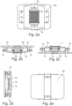
- are a top view, a front view, a back view, a side view and a bottom view of the haptic actuator of
figure 1b , respectively; - Figure 3a
- is another perspective view of the haptic actuator of
figure 1b ; - Figure 3b
- is a cross-sectional view taken along the line X-X' in
figure 3a ; - Figure 3c
- is a cross-sectional view taken along the line Y-Y' in
figure 3a ; - Figures 4a and 4b
- are side views of the haptic actuator of
figures 3a to 3c , in a not activated state and in an activated state, respectively; and - Figures 5a to 5c
- are top view views of three different HMIs.
- As can be seen in
figure 1a , a HMI according to the present disclosure may comprise ahaptic actuator 1 attached to atop touch surface 34 via a printedcircuit board 30 with incorporated sensor and asubstrate 32. The sensor may be a capacitive sensor or any other type of force sensor, like a piezo, strain gauge, or force sensing resistor (FSR) sensor. Thesubstrate 32 may be a stiff material like PMMA, PET, ABS or other plastics or a soft material like a foam, 3D mesh or the like. Thetop touch surface 34 may be an A surface of a vehicle and thus any surface of high efficiency and quality as used in automotive designs. - Further details of the
haptic actuator 1 are shown infigures 1b to 2e in different views. Accordingly, thehaptic actuator 1 comprises coil winding 10 around acoil core 12 and hold by abobbin 11. Thecoil core 12 is ferromagnetic, and has a high magnetic permeability. It extends beyond thebobbin 11 and is fixedly attached to abase plate 40 via connection means 13, which may be in form of two feet, one on each side of the coil winding 10. A vibratingplate 16 is attached to thebase plate 40 via spring means, which may be in form of twoleaf springs coil core 12 is extending beyond the coil winding 10. Further, the vibratingplate 16 is non ferromagnetic, but fixedly attached to aferromagnetic plate 14 extending at least partly parallel to thecoil core 12 between the coil winding 10 and thebase plate 40, via further connection means 15, which may be in form of four supports arranged on both sides of eachspring - Thus, the vibrating
plate 16 together with theferromagnetic plate 14 can move relative to thebase plate 40 up and down, as will be described in detail with respect tofigures 4a and 4b below. A damping material may be inserted between theferromagnetic plate 14 and thebase plate 40 to reduce an activation sound when current is running through the coil winding 10 to push the vibratingplate 16 up-wards infigure 2c . Additionally, the damping material may be inserted between theferromagnetic plate 14 and thebase plate 40 to reduce the sound when current is stopped running. Furthermore, damping material may be inserted between thecoil core 12 and theferromagnetic plate 14, which may reduce the activation sound when current is running.Figure 3 a provides a perspective view of thehaptic actuator 1, whereasfigures 3b and 3c show cross-sections taken along the line X-X' and line Y-Y' infigure 3a , respectively, in order to reveal the relative spatial arrangement of all parts of theactuator 1 described above. - As can be seen e.g. from
figure 3b as well asfigure 4a , theferromagnetic plate 14 extends underneath thecoil core 12 and is designed in such a way that it rests on the non movingbase 40. Agap 50 of below 300 µm is provided between thecoil core 12 and theferromagnetic plate 14 as long as no current is activating thehaptic actuator 1. The gap is designed to be < 300µm, since most haptic vibrations do not require higher values. In the resting state, theferromagnetic plate 14 as well as its connection to the vibratingplate 16 is "resting" on top of thebase plate 40. During this state, any excessive force from outside will not stress thesprings bottom plate 40. - During haptic activation with current flowing through the coil winding 10, the
ferromagnetic plate 14 moves closer to thecoil core 12, making thegap 50 smaller, while agap 60 opens between thecoil core 12 and the vibratingplate 16, as the vibratingplate 16 moves upwards as shown infigure 4b by an arrow. Thus, during the activation state, when current is applied to the coil winding 10, thehaptic actuator 1 is activated, and theferromagnetic plate 14 is attracted / pulled to thecoil core 12 which makes thegap 50 become smaller. The connection to the vibratingplate 16 transfers this movement to e.g. a printed circuit board and a top plate such as thesubstrate 30 and thetouch surface 34 shown infigure 1a . This movement then is interpreted by a user's fingertip as active haptic feedback vibration. - The coil winding 10 is connected to the upper vibrating
plate 16 via thesprings springs plate 16 have to use non ferromagnetic material. Thesprings ferromagnetic plate 14 to its resting position shown infigure 4a when no current is applied. In detail, when the current is stopped, due to gravity and spring force in the arrangement shown infigures 4a and 4b , theferromagnetic plate 14 is brought from its activation position down again to its resting position. - The above-described structure of the
haptic actuator 1 allows to arrange theactuators 1 as required, without a restriction to a horizonal arrangement. Thus, also an HMI as e.g. shown infigure 1 does not require a horizontal placement. Further, multiple actuation in sequence is possible to provide different haptic feedback to user. -
Figures 5a to 5c show howhaptic actuators 1 may be place placed inside a HMI box enclosure. - Multiple actuators can be distributed underneath large HMI components, thanks to a relatively small form factor of each
actuator 1, which may be approx. 60 mm length x 45 mm width x 12.5 mm height. The distribution of multiple actuators across wide surfaces also helps vibration uniformity across the whole surface. -
Figure 5a shows aHMI 100 with sixbuttons 101 to 106 with ahaptic actuator 1 being arranged underbutton buttons -
Figure 5b shows aHMI 200 with oneslider 207 and threebuttons 201 to 203, with ahaptic actuator 1 being arranged underbutton slider 207. -
Figure 5c shows aHMI 300 with onetouchpad area 308 and fourbuttons 301 to 304.Haptic actuators 1 are arranged in thetouchpad area 308 as well as associated with thebuttons - Implementation of actuators in vehicles is increasing. However most of the actuators that are presently used are not designed specifically considering the automotive use case. This brings new challenges on mechanical design to have a proper mechanical decoupling that ensure the components reliability and having a high efficiency on transmitting vibration of energy to HMI surfaces. The haptic actuator according to the present disclosure offers a simplicity for mechanical design since the mechanical decoupling is embedded on the actuator structure, while maintaining the energy transfer efficiency to surface and ensuring mechanical reliability at the same time.
- It will be appreciated by those skilled in the art that changes could be made to the embodiments described above without departing from the broad inventive concept thereof. It is understood, therefore, that the invention disclosed herein is not limited to the particular embodiments disclosed and is intended to cover modifications within the spirit and scope of the present invention.
-
- 1
- actuator
- 10
- coil winding
- 11
- bobbin, coil former
- 12
- coil core
- 13
- connection means
- 14
- ferromagnetic plate
- 15
- connection means
- 16
- vibrating plate
- 18
- spring
- 19
- spring
- 30
- printed circuit board with incorporated sensor
- 32
- substrate
- 34
- top touch surface
- 40
- bottom, base plate
- 50
- gap
- 60
- gap
- 100
- human machine interface
- 101-106
- button
- 200
- human machine interface
- 201-203
- button
- 207
- slider
- 300
- human machine interface
- 301-304
- button
- 308
- touchpad area
Claims (11)
- An active haptic feedback device (1) for a human machine interface (100, 200, 300), comprising a fixed part, a moveable part and a vibrating plate, wherein• the fixed part comprises a coil winding (10) on a bobbin (11) and through which a coil core (12) extends, which is fixed to a base plate (40);• the moveable part comprises a ferromagnetic plate (14) arranged between the coil core (12) and the base plate (40), wherein the ferromagnetic plate (14) has a resting state, when no current is applied to the coil winding (10), with a gap (50) between the ferromagnetic plate (14) and the coil core (12), and an activation state, when current is applied to the coil winding (10), with the gap (50) being reduced due to a movement of the ferromagnetic plate (14) away from the base plate (40) and towards the ferromagnetic plate (14), and• the vibrating plate (16) is arranged on the side of the coil core (12) opposite to the side of the ferromagnetic plate (14) such that the coil core (12) is extending at least partly between the vibrating plate (16) and the ferromagnetic plate (14), wherein the vibrating plate (16) is fixedly attached to the ferromagnetic plate (14) and moveably attached to the base plate (40) via spring means (18, 19), wherein the spring means (18, 19) are configured to bring back the ferromagnetic plate (14) to its resting position when no current is applied to the coil winding (10), from its activation position.
- The active haptic feedback device according to claim 1, whereinthe coil core (12) comprises ferromagnetic material;the vibrating plate (16) is made of non-ferromagnetic material; andconnection means (13, 15) are made of non-ferromagnetic material.
- The active haptic feedback device according to claim 1 or 2, wherein
the spring means (18, 19) comprise leaf springs, at least one on each side of the coil winding (10) perpendicular to the extension of the coil core (12). - The active haptic feedback device according to any one of the preceding claims, wherein the gap (50) is up to 300 µm in the resting state.
- The active haptic feedback device according to any one of the preceding claims, wherein the active haptic feedback device (1) has a length of up to 60 mm, a width of up to 45 mm and a height of up to 12.5 mm.
- The active haptic feedback device according to any one of the preceding claims, wherein damping means are arranged between the ferromagnetic plate (14) and the base plate (40), and/or
damping means are arranged between the coil core (12) and the ferromagnetic plate (14). - A human machine interface (100, 200, 300) with at least one active haptic feedback device (1) according to any one of the preceding claims.
- The human machine interface according to claim 7, wherein
a touch surface (34) is arranged on the vibrating plate (16) of the at least one active haptic feedback device (1), such that movement of the vibrating plate (16) together with the ferromagnetic plate (14) from the resting state to the activation state is in the direction towards the touch surface (34). - The human machine interface according to claim 7 or 8, wherein
a printed circuit board (30) with at least one incorporated sensor and a substrate (32) are arranged between the touch surface (34) and the at least one active haptic feedback device (1). - The human machine interface according to any one of the claims 7 to 9, comprising at least one button (101, 106, 201, 203) associated with an active haptic feedback device (1); at least one slide (207) associated with at least two active haptic feedback devices (1); and/or at least one touchpad area (308) associated with at least two active haptic feedback devices (1).
- Automotive part with at least one human machine interface (100, 200, 300) according to any one of the claims 7 to 10.
Applications Claiming Priority (1)
| Application Number | Priority Date | Filing Date | Title |
|---|---|---|---|
| DE102023134035.2A DE102023134035B3 (en) | 2023-12-05 | 2023-12-05 | Active haptic feedback device, human-machine interface and automotive part |
Publications (2)
| Publication Number | Publication Date |
|---|---|
| EP4567566A1 true EP4567566A1 (en) | 2025-06-11 |
| EP4567566B1 EP4567566B1 (en) | 2025-12-17 |
Family
ID=93799677
Family Applications (1)
| Application Number | Title | Priority Date | Filing Date |
|---|---|---|---|
| EP24217595.8A Active EP4567566B1 (en) | 2023-12-05 | 2024-12-04 | Active haptic feedback device, human machine interface and automotive part |
Country Status (4)
| Country | Link |
|---|---|
| US (1) | US12437910B2 (en) |
| EP (1) | EP4567566B1 (en) |
| CN (1) | CN120103963A (en) |
| DE (1) | DE102023134035B3 (en) |
Citations (3)
| Publication number | Priority date | Publication date | Assignee | Title |
|---|---|---|---|---|
| US20100060437A1 (en) * | 2008-09-05 | 2010-03-11 | Dräxlmaier GmbH | Operating control having specific feedback |
| US20120299857A1 (en) * | 2004-10-08 | 2012-11-29 | Immersion Corporation | Haptic Feedback for Button and Scrolling Action Simulation in Touch Input Devices |
| EP3888806A1 (en) | 2018-11-30 | 2021-10-06 | Minebea Mitsumi Inc. | Control device |
Family Cites Families (11)
| Publication number | Priority date | Publication date | Assignee | Title |
|---|---|---|---|---|
| FR2938669B1 (en) * | 2008-11-17 | 2010-12-17 | Dav | HAPTIC RETURN CONTROL DEVICE AND CORRESPONDING ACTUATOR |
| JP4875133B2 (en) * | 2009-10-29 | 2012-02-15 | 日本電産コパル株式会社 | Vibration actuator |
| DE102015008537A1 (en) * | 2015-07-02 | 2017-01-05 | Audi Ag | Motor vehicle operating device with haptic feedback |
| AU2017206677A1 (en) * | 2016-01-12 | 2018-07-26 | Electrolux Home Products, Inc. | Miniature printed circuit board mounted haptic device |
| DE102016005926A1 (en) * | 2016-05-14 | 2017-11-16 | Leopold Kostal Gmbh & Co. Kg | Electromagnetic feedback actuator for a control element and arrangement with at least one electromagnetic feedback actuator |
| WO2017219137A1 (en) * | 2016-06-24 | 2017-12-28 | Nanoport Technology Inc. | Tactile feedback actuator, electronic device using same, and method of operating same |
| CN109475905B (en) * | 2016-08-09 | 2021-03-09 | 日本电产三协株式会社 | Linear Actuator |
| US20180076702A1 (en) * | 2016-09-14 | 2018-03-15 | Nidec Seimitsu Corporation | Vibration motor |
| JP2019180149A (en) * | 2018-03-30 | 2019-10-17 | 日本電産サンキョー株式会社 | Actuator |
| CN113659793A (en) * | 2020-05-12 | 2021-11-16 | 星电株式会社 | Electromagnetic actuator and vibration generator including the same |
| DE102021129743A1 (en) * | 2021-10-26 | 2023-04-27 | Behr-Hella Thermocontrol Gmbh | Actuator for generating active haptic feedback in an operating unit, in particular for a vehicle |
-
2023
- 2023-12-05 DE DE102023134035.2A patent/DE102023134035B3/en active Active
-
2024
- 2024-10-03 US US18/905,463 patent/US12437910B2/en active Active
- 2024-11-12 CN CN202411604920.4A patent/CN120103963A/en active Pending
- 2024-12-04 EP EP24217595.8A patent/EP4567566B1/en active Active
Patent Citations (3)
| Publication number | Priority date | Publication date | Assignee | Title |
|---|---|---|---|---|
| US20120299857A1 (en) * | 2004-10-08 | 2012-11-29 | Immersion Corporation | Haptic Feedback for Button and Scrolling Action Simulation in Touch Input Devices |
| US20100060437A1 (en) * | 2008-09-05 | 2010-03-11 | Dräxlmaier GmbH | Operating control having specific feedback |
| EP3888806A1 (en) | 2018-11-30 | 2021-10-06 | Minebea Mitsumi Inc. | Control device |
Also Published As
| Publication number | Publication date |
|---|---|
| CN120103963A (en) | 2025-06-06 |
| US12437910B2 (en) | 2025-10-07 |
| DE102023134035B3 (en) | 2025-04-24 |
| EP4567566B1 (en) | 2025-12-17 |
| US20250182945A1 (en) | 2025-06-05 |
Similar Documents
| Publication | Publication Date | Title |
|---|---|---|
| KR102923121B1 (en) | Vibration actuator and vibration presenting device | |
| JP7605554B2 (en) | Vibration actuator and vibration presentation device | |
| KR101016208B1 (en) | Mixed actuator using vibration generating means and electromagnetic force generating means, vibration haptic providing device using same, display device using same and control method thereof | |
| KR20120125353A (en) | Tactile feedback device | |
| US20140009005A1 (en) | Haptic actuators | |
| JP7472932B2 (en) | Key input device | |
| CN108351703B (en) | Actuator for a touch interface module, touch interface module and method for generating haptic feedback | |
| CN211830531U (en) | Linear vibration motor and electronic apparatus | |
| CN115136102B (en) | Haptic device and haptic module | |
| CN109074984A (en) | Electromagnetic feedback actuator for operating elements and device with at least one electromagnetic feedback actuator | |
| EP3845318B1 (en) | Operation device and vibration generating device | |
| KR102782470B1 (en) | Vibration actuators and contact input devices | |
| US12437910B2 (en) | Active haptic feedback device, human machine interface and automotive part | |
| KR20140095394A (en) | Piezo Actuator | |
| CN113659767B (en) | Electronic device | |
| JP7410705B2 (en) | Actuators and haptic devices | |
| KR20220063072A (en) | Magneto-Rheological Elastomer Haptic Device and Haptic Module | |
| KR101061894B1 (en) | Small actuator device and haptic feedback method using the same | |
| KR20140088678A (en) | Piezo Actuator | |
| KR20230123371A (en) | Vibration generator assembly of one body | |
| KR20250086909A (en) | A rigidity-changing haptic pads with magnetic flux elasticity | |
| WO2025047930A1 (en) | Vibration actuator and contact-type input device | |
| KR20230118225A (en) | Touchpad with Vibration actuator | |
| KR20230077524A (en) | Vibration Generator | |
| KR20140079679A (en) | Piezo Actuator |
Legal Events
| Date | Code | Title | Description |
|---|---|---|---|
| PUAI | Public reference made under article 153(3) epc to a published international application that has entered the european phase |
Free format text: ORIGINAL CODE: 0009012 |
|
| STAA | Information on the status of an ep patent application or granted ep patent |
Free format text: STATUS: THE APPLICATION HAS BEEN PUBLISHED |
|
| STAA | Information on the status of an ep patent application or granted ep patent |
Free format text: STATUS: REQUEST FOR EXAMINATION WAS MADE |
|
| AK | Designated contracting states |
Kind code of ref document: A1 Designated state(s): AL AT BE BG CH CY CZ DE DK EE ES FI FR GB GR HR HU IE IS IT LI LT LU LV MC ME MK MT NL NO PL PT RO RS SE SI SK SM TR |
|
| 17P | Request for examination filed |
Effective date: 20250520 |
|
| GRAP | Despatch of communication of intention to grant a patent |
Free format text: ORIGINAL CODE: EPIDOSNIGR1 |
|
| STAA | Information on the status of an ep patent application or granted ep patent |
Free format text: STATUS: GRANT OF PATENT IS INTENDED |
|
| INTG | Intention to grant announced |
Effective date: 20250707 |
|
| GRAS | Grant fee paid |
Free format text: ORIGINAL CODE: EPIDOSNIGR3 |
|
| GRAA | (expected) grant |
Free format text: ORIGINAL CODE: 0009210 |
|
| STAA | Information on the status of an ep patent application or granted ep patent |
Free format text: STATUS: THE PATENT HAS BEEN GRANTED |
|
| AK | Designated contracting states |
Kind code of ref document: B1 Designated state(s): AL AT BE BG CH CY CZ DE DK EE ES FI FR GB GR HR HU IE IS IT LI LT LU LV MC ME MK MT NL NO PL PT RO RS SE SI SK SM TR |
|
| REG | Reference to a national code |
Ref country code: CH Ref legal event code: F10 Free format text: ST27 STATUS EVENT CODE: U-0-0-F10-F00 (AS PROVIDED BY THE NATIONAL OFFICE) Effective date: 20251217 Ref country code: GB Ref legal event code: FG4D |
|
| REG | Reference to a national code |
Ref country code: DE Ref legal event code: R096 Ref document number: 602024001744 Country of ref document: DE |
|
| REG | Reference to a national code |
Ref country code: CH Ref legal event code: W10 Free format text: ST27 STATUS EVENT CODE: U-0-0-W10-W00 (AS PROVIDED BY THE NATIONAL OFFICE) Effective date: 20260225 |
|
| RAP4 | Party data changed (patent owner data changed or rights of a patent transferred) |
Owner name: MOTHERSON INNOVATIONS COMPANY LIMITED |
|
| P01 | Opt-out of the competence of the unified patent court (upc) registered |
Free format text: CASE NUMBER: UPC_APP_0008324_4567566/2026 Effective date: 20260227 |
|
| REG | Reference to a national code |
Ref country code: LT Ref legal event code: MG9D |
|
| PG25 | Lapsed in a contracting state [announced via postgrant information from national office to epo] |
Ref country code: NO Free format text: LAPSE BECAUSE OF FAILURE TO SUBMIT A TRANSLATION OF THE DESCRIPTION OR TO PAY THE FEE WITHIN THE PRESCRIBED TIME-LIMIT Effective date: 20260317 |
|
| PG25 | Lapsed in a contracting state [announced via postgrant information from national office to epo] |
Ref country code: FI Free format text: LAPSE BECAUSE OF FAILURE TO SUBMIT A TRANSLATION OF THE DESCRIPTION OR TO PAY THE FEE WITHIN THE PRESCRIBED TIME-LIMIT Effective date: 20251217 Ref country code: HR Free format text: LAPSE BECAUSE OF FAILURE TO SUBMIT A TRANSLATION OF THE DESCRIPTION OR TO PAY THE FEE WITHIN THE PRESCRIBED TIME-LIMIT Effective date: 20251217 |
|
| PG25 | Lapsed in a contracting state [announced via postgrant information from national office to epo] |
Ref country code: RS Free format text: LAPSE BECAUSE OF FAILURE TO SUBMIT A TRANSLATION OF THE DESCRIPTION OR TO PAY THE FEE WITHIN THE PRESCRIBED TIME-LIMIT Effective date: 20260317 |
|
| REG | Reference to a national code |
Ref country code: DE Ref legal event code: R084 Ref document number: 602024001744 Country of ref document: DE |
|
| REG | Reference to a national code |
Ref country code: NL Ref legal event code: MP Effective date: 20251217 |
|
| PG25 | Lapsed in a contracting state [announced via postgrant information from national office to epo] |
Ref country code: LV Free format text: LAPSE BECAUSE OF FAILURE TO SUBMIT A TRANSLATION OF THE DESCRIPTION OR TO PAY THE FEE WITHIN THE PRESCRIBED TIME-LIMIT Effective date: 20251217 |
|
| PG25 | Lapsed in a contracting state [announced via postgrant information from national office to epo] |
Ref country code: BG Free format text: LAPSE BECAUSE OF FAILURE TO SUBMIT A TRANSLATION OF THE DESCRIPTION OR TO PAY THE FEE WITHIN THE PRESCRIBED TIME-LIMIT Effective date: 20251217 |