EP4567521A1 - Developing device and image forming apparatus - Google Patents
Developing device and image forming apparatus Download PDFInfo
- Publication number
- EP4567521A1 EP4567521A1 EP24216743.5A EP24216743A EP4567521A1 EP 4567521 A1 EP4567521 A1 EP 4567521A1 EP 24216743 A EP24216743 A EP 24216743A EP 4567521 A1 EP4567521 A1 EP 4567521A1
- Authority
- EP
- European Patent Office
- Prior art keywords
- developer
- developing device
- spiral blade
- housing
- lack
- Prior art date
- Legal status (The legal status is an assumption and is not a legal conclusion. Google has not performed a legal analysis and makes no representation as to the accuracy of the status listed.)
- Pending
Links
Images


Classifications
-
- G—PHYSICS
- G03—PHOTOGRAPHY; CINEMATOGRAPHY; ANALOGOUS TECHNIQUES USING WAVES OTHER THAN OPTICAL WAVES; ELECTROGRAPHY; HOLOGRAPHY
- G03G—ELECTROGRAPHY; ELECTROPHOTOGRAPHY; MAGNETOGRAPHY
- G03G15/00—Apparatus for electrographic processes using a charge pattern
- G03G15/06—Apparatus for electrographic processes using a charge pattern for developing
- G03G15/08—Apparatus for electrographic processes using a charge pattern for developing using a solid developer, e.g. powder developer
- G03G15/0822—Arrangements for preparing, mixing, supplying or dispensing developer
- G03G15/0887—Arrangements for conveying and conditioning developer in the developing unit, e.g. agitating, removing impurities or humidity
- G03G15/0891—Arrangements for conveying and conditioning developer in the developing unit, e.g. agitating, removing impurities or humidity for conveying or circulating developer, e.g. augers
- G03G15/0893—Arrangements for conveying and conditioning developer in the developing unit, e.g. agitating, removing impurities or humidity for conveying or circulating developer, e.g. augers in a closed loop within the sump of the developing device
-
- G—PHYSICS
- G03—PHOTOGRAPHY; CINEMATOGRAPHY; ANALOGOUS TECHNIQUES USING WAVES OTHER THAN OPTICAL WAVES; ELECTROGRAPHY; HOLOGRAPHY
- G03G—ELECTROGRAPHY; ELECTROPHOTOGRAPHY; MAGNETOGRAPHY
- G03G15/00—Apparatus for electrographic processes using a charge pattern
- G03G15/06—Apparatus for electrographic processes using a charge pattern for developing
- G03G15/08—Apparatus for electrographic processes using a charge pattern for developing using a solid developer, e.g. powder developer
- G03G15/0806—Apparatus for electrographic processes using a charge pattern for developing using a solid developer, e.g. powder developer on a donor element, e.g. belt, roller
- G03G15/0812—Apparatus for electrographic processes using a charge pattern for developing using a solid developer, e.g. powder developer on a donor element, e.g. belt, roller characterised by the developer regulating means, e.g. structure of doctor blade
-
- G—PHYSICS
- G03—PHOTOGRAPHY; CINEMATOGRAPHY; ANALOGOUS TECHNIQUES USING WAVES OTHER THAN OPTICAL WAVES; ELECTROGRAPHY; HOLOGRAPHY
- G03G—ELECTROGRAPHY; ELECTROPHOTOGRAPHY; MAGNETOGRAPHY
- G03G15/00—Apparatus for electrographic processes using a charge pattern
- G03G15/06—Apparatus for electrographic processes using a charge pattern for developing
- G03G15/08—Apparatus for electrographic processes using a charge pattern for developing using a solid developer, e.g. powder developer
- G03G15/0822—Arrangements for preparing, mixing, supplying or dispensing developer
- G03G15/0844—Arrangements for purging used developer from the developing unit
-
- G—PHYSICS
- G03—PHOTOGRAPHY; CINEMATOGRAPHY; ANALOGOUS TECHNIQUES USING WAVES OTHER THAN OPTICAL WAVES; ELECTROGRAPHY; HOLOGRAPHY
- G03G—ELECTROGRAPHY; ELECTROPHOTOGRAPHY; MAGNETOGRAPHY
- G03G15/00—Apparatus for electrographic processes using a charge pattern
- G03G15/06—Apparatus for electrographic processes using a charge pattern for developing
- G03G15/08—Apparatus for electrographic processes using a charge pattern for developing using a solid developer, e.g. powder developer
- G03G15/0822—Arrangements for preparing, mixing, supplying or dispensing developer
- G03G15/0887—Arrangements for conveying and conditioning developer in the developing unit, e.g. agitating, removing impurities or humidity
- G03G15/0891—Arrangements for conveying and conditioning developer in the developing unit, e.g. agitating, removing impurities or humidity for conveying or circulating developer, e.g. augers
-
- G—PHYSICS
- G03—PHOTOGRAPHY; CINEMATOGRAPHY; ANALOGOUS TECHNIQUES USING WAVES OTHER THAN OPTICAL WAVES; ELECTROGRAPHY; HOLOGRAPHY
- G03G—ELECTROGRAPHY; ELECTROPHOTOGRAPHY; MAGNETOGRAPHY
- G03G21/00—Arrangements not provided for by groups G03G13/00 - G03G19/00, e.g. cleaning, elimination of residual charge
- G03G21/10—Collecting or recycling waste developer
- G03G21/105—Arrangements for conveying toner waste
-
- G—PHYSICS
- G03—PHOTOGRAPHY; CINEMATOGRAPHY; ANALOGOUS TECHNIQUES USING WAVES OTHER THAN OPTICAL WAVES; ELECTROGRAPHY; HOLOGRAPHY
- G03G—ELECTROGRAPHY; ELECTROPHOTOGRAPHY; MAGNETOGRAPHY
- G03G21/00—Arrangements not provided for by groups G03G13/00 - G03G19/00, e.g. cleaning, elimination of residual charge
- G03G21/10—Collecting or recycling waste developer
- G03G21/12—Toner waste containers
-
- G—PHYSICS
- G03—PHOTOGRAPHY; CINEMATOGRAPHY; ANALOGOUS TECHNIQUES USING WAVES OTHER THAN OPTICAL WAVES; ELECTROGRAPHY; HOLOGRAPHY
- G03G—ELECTROGRAPHY; ELECTROPHOTOGRAPHY; MAGNETOGRAPHY
- G03G2215/00—Apparatus for electrophotographic processes
- G03G2215/08—Details of powder developing device not concerning the development directly
- G03G2215/0802—Arrangements for agitating or circulating developer material
- G03G2215/0816—Agitator type
- G03G2215/0819—Agitator type two or more agitators
- G03G2215/0822—Agitator type two or more agitators with wall or blade between agitators
-
- G—PHYSICS
- G03—PHOTOGRAPHY; CINEMATOGRAPHY; ANALOGOUS TECHNIQUES USING WAVES OTHER THAN OPTICAL WAVES; ELECTROGRAPHY; HOLOGRAPHY
- G03G—ELECTROGRAPHY; ELECTROPHOTOGRAPHY; MAGNETOGRAPHY
- G03G2215/00—Apparatus for electrophotographic processes
- G03G2215/08—Details of powder developing device not concerning the development directly
- G03G2215/0802—Arrangements for agitating or circulating developer material
- G03G2215/0816—Agitator type
- G03G2215/0827—Augers
-
- G—PHYSICS
- G03—PHOTOGRAPHY; CINEMATOGRAPHY; ANALOGOUS TECHNIQUES USING WAVES OTHER THAN OPTICAL WAVES; ELECTROGRAPHY; HOLOGRAPHY
- G03G—ELECTROGRAPHY; ELECTROPHOTOGRAPHY; MAGNETOGRAPHY
- G03G2215/00—Apparatus for electrophotographic processes
- G03G2215/08—Details of powder developing device not concerning the development directly
- G03G2215/0802—Arrangements for agitating or circulating developer material
- G03G2215/0816—Agitator type
- G03G2215/0827—Augers
- G03G2215/083—Augers with two opposed pitches on one shaft
Definitions
- An electrophotographic image forming apparatus includes a developing device which develops an electrostatic latent image formed on a photosensitive drum by using toner.
- the developing device using a two-component developer containing toner and carrier is provided with a developing housing which stores the developer, a developing roller which supplies the toner to the photosensitive drum, and a stirring member which conveys the developer to the developing roller while stirring the developer.
- a predetermined amount of the carrier is continuously replaced by replenishing the developer and discharging the excessive developer.
- JP2011-128527 and JP2015-102572 disclose a configuration in which a regulating member is provided to block the developer conveyed by the stirring member, and the developer got over the regulating member is discharged through a discharge port.
- the developing device must be designed according to a processing speed required for the image forming apparatus. For example, comparing a high-speed machine with a low-speed machine, the high-speed machine requires a larger amount of the developer supplied per unit time and a larger amount of the excessive developer discharged per unit time.
- a size of the housing also needs to be varied, so that there is a problem that a size of the housing increases as the speed increases. Further, there is a problem that changing a size of the housing causes an increase in cost.
- An image forming apparatus includes a photosensitive drum on which an electrostatic latent image is formed, and the developing device which supplies the developer to the photosensitive drum.
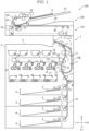
- FIG. 1 is a front view schematically showing an internal configuration of the image forming apparatus 100.
- the front side of the paper plane on which FIG. 1 is drawn is defined as the front side of the image forming apparatus 100, and the left-and-right direction is described with reference to the direction in which the image forming apparatus 100 is viewed from the front side.
- U, Lo, L, R, Fr, and Rr indicate the upper, lower, left, right, front, and rear, respectively.
- the image forming apparatus 100 includes a printer 1, a scanner 110, and a document conveying device 120.
- the scanner 110 is provided above the printer 1, and the document conveying device 120 is provided above the scanner 110.
- the document conveying device 120 conveys a document via a reading position of the scanner 110.
- the scanner 110 is a flatbed type image scanner, and reads the document to generate image data.
- the printer 1 forms an image based on the image data on a sheet S.
- the printer 1 includes a rectangular parallelepiped body housing 3.
- a sheet feeding cassette 4 which stores the sheet S and the sheet feeding roller 5 which feeds the sheet S rightward from the sheet feeding cassette 4 are provided.
- an image forming unit 6 which forms a toner image by an electrophotographic method is provided, and a fixing device 7 which fixes the toner image to the sheet S is provided on the right upper side of the image forming unit 6.
- a discharge roller 8 which discharges the sheet S on which the toner image is fixed and a discharge tray 9 on which the discharged sheet S is stacked are provided.
- a conveyance path 10 is provided from the sheet feeding roller 5 to the discharge roller 8 via the image forming unit 6 and the fixing device 7.
- the conveyance path 10 is formed by using plate-like members facing each other with a gap for passing the sheet S.
- a conveying roller 17 which holds and conveys the sheet S is provided at a plurality of positions on the conveyance path 10.
- a registration roller 18 is provided on the upstream side of the image forming unit 6 in the conveyance direction Y.
- the image forming unit 6 is provided with a photosensitive drum 11 whose potential is changed by irradiation with light, a charging device 12 which charges the photosensitive drum 11, an exposure device 13 which emits laser light corresponding to the image data, a developing device 14 which supplies toner to the photosensitive drum 11, an intermediate transfer unit 15 which transfers the toner image from the photosensitive drum 11 to the sheet S, and a cleaning device 16 which removes the toner remaining on the photosensitive drum 11.
- the intermediate transfer unit 15 includes an endless intermediate transfer belt 15B wound around a driving roller 15D and a driven roller 15N, a primary transfer roller 151 facing the inner circumferential surface of the intermediate transfer belt 15B at a position corresponding to the photosensitive drum 11 and generating a primary transfer bias, and a secondary transfer roller 152 facing the outer circumferential surface of the intermediate transfer belt 15B at a position corresponding to the driving roller 15D and generating a secondary transfer bias.
- a toner container 20 for supplying the toner to the developing device 14 is connected to the developing device 14.
- the image forming unit 6 includes four sets of the photosensitive drum 11, the charging device 12, the exposure device 13, the developing device 14, the primary transfer roller 151, the cleaning device 16, and the toner container 20, and forms a color image by superposing the toner images of four colors on the intermediate transfer belt 15B.
- the present disclosure may be applied to the image forming apparatus 100 for forming a color image with toner of three or less colors or five or more colors.
- the control part 2 includes an arithmetic part and a storage part.
- the arithmetic part is, for example, a CPU (Central Processing Unit).
- the storage unit includes a storage medium such as a ROM (Read Only Memory), a RAM (Random Access Memory), and an EEPROM (Electrically Erasable Programmable Read Only Memory).
- the arithmetic part reads and executes the control program stored in the storage part to perform various processes.
- the control part 2 may be realized only by an integrated circuit without using software.
- a display operation part (not shown) is provided on the front side of the scanner 110.
- the display operation part includes a display panel, a touch panel provided superposed on the display surface of the display panel, and a keypad adjacent to the display panel.
- the control part 2 displays a screen indicating the operation menu, status, and the like of the printer 1 and the scanner 110 on the display panel, and controls the respective parts of the printer 1 and the scanner 110 according to the operation detected by the touch panel and the keypad.
- the basic image forming operation of the printer 1 is as follows.
- the sheet feeding roller 5 feeds the sheet S from the sheet feeding cassette 4 to the conveyance path 10
- the registration roller 18 whose rotation is stopped corrects the skew of the sheet S
- the registration roller 18 sends the sheet S to the image forming unit 6 at a predetermined timing.
- the charging device 12 charges the photosensitive drum 11 to a predetermined potential
- the exposure device 13 writes an electrostatic latent image on the photosensitive drum 11
- the developing device 14 develops the electrostatic latent image using the toner supplied from the toner container 20 to form the toner image
- the primary transfer roller 151 transfers the toner image to the intermediate transfer belt 15B
- the secondary transfer roller 152 transfers the toner image to the sheet S.
- the fixing device 7 fixes the toner image to the sheet S by melting the toner image while holding and conveying the sheet S
- the discharge roller 8 discharges the sheet S to the discharge tray 9.
- the cleaning device 16 removes the toner remaining on the photosensitive drum 11.
- the sheet S having the toner image fixed on the first surface is fed into the conveyance path 10 via the inversion conveyance path 10R, then the toner image is transferred to the second surface.
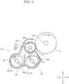
- FIG. 2 is a front view schematically showing an internal configuration of the developing device 14.
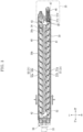
- FIG. 3 is a cross-sectional view showing the internal configuration of a first conveying chamber 40 and a second conveying chamber 41.
- FIG. 4 is an enlarged cross-sectional view showing the rear portions of the first conveying chamber 40 and the second conveying chamber 41.
- the four developing devices 14 have the same configuration.
- the developing device 14 (see FIG. 2 and FIG. 3 ) includes a housing 30, a stirring member 31, a developing roller 53, and a driving device 33.
- the housing 30 houses a developer containing the toner and carrier.
- the stirring member 31 stirrers the developer in the housing 30 while conveying the developer.
- the developing roller 53 conveys the developer in the housing 30 from the stirring member 31 toward the photosensitive drum 11.
- the driving device 33 rotates the stirring member 31 and the developing roller 53.
- the housing 30 is made of, for example, resin material.
- the housing 30 is formed elongated in the front-and-rear direction.
- An opening 30a (see FIG. 2 ) is formed on the upper right side surface of the housing 30.
- a partition wall 30b (see FIG. 2 to FIG. 4 ) is provided on the inner bottom of the housing 30 along the longitudinal direction of the housing 30.
- the partition wall 30b partitions the internal space of the housing 30 into a first conveying chamber 40 and a second conveying chamber 41.
- the first conveying chamber 40 and the second conveying chamber 41 are provided in parallel to each other.
- the driving device 33 (see FIG. 3 ) is an electric motor for transmitting a driving force to the first stirring member 50, the second stirring member 51, and the developing roller 53 via a gear train 58.
- the driving device 33 is driven, the first stirring member 50, the second stirring member 51 and the developing roller 53 are rotated.
- FIG. 5 is a perspective view showing the rear portions of the first conveying chamber 40 and the second conveying chamber 41.
- FIG. 6 is a perspective view showing cross-sections of the rear portions of the first conveying chamber 40 and the second conveying chamber 41.
- the regulating member 60 is provided between the spiral blade 51b and the reverse spiral blade 51c of the second stirring member 51.
- the regulating member 60 regulates the conveyance of the developer to the discharge port 47.
- the regulating member 60 is a disk-shaped member.
- the regulating member 60 is provided on the rotational shaft portion 51a of the second stirring member 51.
- the center of the rotational shaft portion 51a coincides with the center of the regulating member 60.
- the regulating member 60 rotates together with the rotational shaft portion 51a and the spiral blade 51b.
- the regulating member 60 has a lack portion 60a penetrating in the conveyance direction (the direction B in FIG. 4 ).
- the lack portion 60a is a slit formed along the radial direction.
- the lack portion 60a is provided at a position circumferentially spaced from the downstream end portion 51e of the spiral blade 51b in the conveyance direction (the direction B).
- the developer supplied from the toner container 20 to the housing 30 through the replenishment port 30c (see FIG. 3 and FIG. 4 ) is conveyed in the direction A in the first conveying chamber 40 by the first stirring member 50, moved to the second conveying chamber 41 through the communication portion 42, and conveyed in the direction B by the second stirring member 51.
- the developer conveyed in the direction B is blocked by the regulating member 60 and moves mainly in three flows.
- the developer moves in the flow to the communication portion 43, the flow passing over the regulating member 60, and the flow through the lack portion 60a.
- the developer flowing to the communication portion 43 flows to the first conveying chamber 40, and the stirring and conveying are continued.
- the developer passing over the regulating member 60 is mainly divided into two flows. A part of the developer passed over the regulating member 60 is pushed back by the reverse spiral blade 51c and flows to the first conveying chamber 40 through the communication portion 43. The other developer passes over the reverse spiral blade 51c, is conveyed in the direction B by the discharge blade 51d, and is discharged from the discharge port 47 as the excessive developer.
- the developer passed through the lack portion 60a is pushed back by the reverse spiral blade 51c and flows to the first conveying chamber 40 through the communication portion 43. That is, a discharge amount of the excessive developer varies depending on an amount of the developer passing through the lack portion 60a.
- an amount of the developer passing through the lack portion 60a may be reduced. For example, by reducing a number of the lack portion 60a or reducing a size of the lack portion 60a, an amount of the developer passing through the lack portion 60a is reduced.
- An amount of the developer passing through the lack portion 60a also varies depending on a circumferential position of the lack portion 60a. If the lack portion 60a is adjacent to the downstream end portion 51e of the spiral blade 51b in the conveyance direction (the direction B), the developer flows directly into the lack portion 60a from the end portion 51e, and an amount of the developer passing through the lack portion 60a increases. On the other hand, when the lack portion 60a is circumferentially separated from the end portion 51e, the developer is temporarily blocked by the regulating member 60. Since a part of the developer passes over the regulating member 60 during the blocking, an amount of the developer passing through the lack portion 60a is reduced. The longer the distance between the lack portion 60a and the end portion 51e, the longer the time for blocking the developer, and therefore, the greater the amount of developer passing over the regulating member 60, and the smaller the amount of developer passing through the lack portion 60a.
- the high-speed apparatus consumes more toner per unit time than the low-speed apparatus, so that an amount of the carriers remaining in the housing 30 also increases. Therefore, the high-speed apparatus needs to increase a discharge amount of the excessive developer per unit time.
- a discharge amount of the excessive developer varies depending on the number, size, and position of the lack portion 60a. Therefore, according to the present embodiment, a discharge amount of the excessive developer can be optimized without changing the size of the developing device 14.
- the developing device 14 includes the housing 30 which stores the developer, the replenishment port 30c through which the developer is supplied to the housing 30, the spiral blade 51b which stirrers the developer in the housing 30 while conveying the developer in the predetermined conveyance direction (the direction B), the discharge port 47 through which the developer conveyed by the spiral blade 51b is discharged, and the regulating member 60 which is provided between the spiral blade 51b and the discharge port 47 and regulates the conveyance of the developer to the discharge port 47, wherein the regulating member 60 has the lack portion 60a penetrating in the conveyance direction (the direction B).
- the lack portion 60a is circumferentially separated from the downstream end portion 51e of the spiral blade 51b in the conveyance direction (the direction B). According to this configuration, since a discharge amount of the excessive developer varies depending on the distance between the lack portion 60a and the downstream end portion 51e of the spiral blade 51b in the conveyance direction (the direction B), a discharge amount of the excessive developer can be optimized without changing the size of the developing device 14.
- the lack portion 60a is a slit formed along the radial direction. According to this configuration, since the lack portion 60a is formed by attaching the two semicircular plates facing each other to the rotational shaft portion 51a, the lack portion 60a can be formed with a simple configuration.
- the image forming apparatus 100 includes the photosensitive drum 11 on which an electrostatic latent image is formed, and the developing device 14 which supplies the developer to the photosensitive drum 11. According to this configuration, the image can be formed with accurate density.
- the regulating member 60 is provided between the spiral blade 51b and the reverse spiral blade 51c, but the reverse spiral blade 51c may have the function of the regulating member 60.
- the lack portion 60a may be provided in the forwardmost portion (on a side of the spiral blade 51b) of the reverse spiral blade 51c.
- the lack portion 60a of the regulating member 60 is a slit formed along the radial direction, but the lack portion 60a may have another shape.
- the lack portion 60a may be a hole, and the shape of the hole may be circular or polygonal.
Landscapes
- Physics & Mathematics (AREA)
- General Physics & Mathematics (AREA)
- Life Sciences & Earth Sciences (AREA)
- Engineering & Computer Science (AREA)
- Environmental & Geological Engineering (AREA)
- Sustainable Development (AREA)
- Dry Development In Electrophotography (AREA)
Abstract
A developing device (14) includes a housing (30), a replenishment port (30c), a spiral blade (50b), a discharge port (47), and a regulating member (60). The housing (30) houses a developer. Through the replenishment port (30c), the developer is replenished to the housing (30). The spiral blade (50b) stirrers the developer in the housing (30) while conveying the developer in a predetermined conveyance direction. Through the discharge port (47), the developer conveyed by the spiral blade (50b) is discharged. The regulating member (60) is disposed between the spiral blade (50b) and the discharge port (47), and regulates a conveyance of the developer to the discharge port (47). The regulating member (60) has a lack portion (60a) penetrating in the conveyance direction.
Description
- The present disclosure relates to a developing device and an image forming apparatus.
- An electrophotographic image forming apparatus includes a developing device which develops an electrostatic latent image formed on a photosensitive drum by using toner. The developing device using a two-component developer containing toner and carrier is provided with a developing housing which stores the developer, a developing roller which supplies the toner to the photosensitive drum, and a stirring member which conveys the developer to the developing roller while stirring the developer. In this configuration, while the toner is consumed by the developing, the carrier remains in the developing housing, so that as the developing operation is repeated, the carrier deteriorates to decrease a frictional charging ability with respect to the toner. Therefore, there is known a configuration in which a predetermined amount of the carrier is continuously replaced by replenishing the developer and discharging the excessive developer. For example,
JP2011-128527 JP2015-102572 - The developing device must be designed according to a processing speed required for the image forming apparatus. For example, comparing a high-speed machine with a low-speed machine, the high-speed machine requires a larger amount of the developer supplied per unit time and a larger amount of the excessive developer discharged per unit time. When the above-described configuration is adopted, in order to vary a discharge amount of the excessive developer, it is necessary to vary specifications (number of turns, pitch, diameter, and the others) of the stirring member, but a size of the housing also needs to be varied, so that there is a problem that a size of the housing increases as the speed increases. Further, there is a problem that changing a size of the housing causes an increase in cost.
- A developing device according to the present disclosure includes a housing, a replenishment port, a spiral blade, a discharge port, and a regulating member. The housing houses a developer. Through the replenishment port, the developer is replenished to the housing. The spiral blade stirrers the developer in the housing while conveying the developer in a predetermined conveyance direction. Through the discharge port, the developer conveyed by the spiral blade is discharged. The regulating member is disposed between the spiral blade and the discharge port, and regulates a conveyance of the developer to the discharge port. The regulating member has a lack portion penetrating in the conveyance direction.
- An image forming apparatus according to the present disclosure includes a photosensitive drum on which an electrostatic latent image is formed, and the developing device which supplies the developer to the photosensitive drum.
-
-
FIG. 1 is a front view schematically showing an internal configuration of an image forming apparatus according to one embodiment of the present disclosure. -
FIG. 2 is a front view schematically showing an internal configuration of a developing device according to the embodiment of the present disclosure. -
FIG. 3 is a cross-sectional view showing an internal configuration of a first conveying chamber and a second conveying chamber according to the embodiment of the present disclosure. -
FIG. 4 is an enlarged cross-sectional view showing the rear portions of the first conveying chamber and the second conveying chamber according to the embodiment of the present disclosure. -
FIG. 5 is a perspective view showing the rear portions of the first conveying chamber and the second conveying chamber according to the embodiment of the present disclosure. -
FIG. 6 is a perspective view showing a cross-section of the rear portions of the first conveying chamber and the second conveying chamber according to the embodiment of the present disclosure. - Hereinafter, with reference to the drawings, a developing
device 14 and animage forming apparatus 100 according to one embodiment of the present disclosure will be described. - First, the entire configuration of the
image forming apparatus 100 will be described.FIG. 1 is a front view schematically showing an internal configuration of theimage forming apparatus 100. Hereinafter, the front side of the paper plane on whichFIG. 1 is drawn is defined as the front side of theimage forming apparatus 100, and the left-and-right direction is described with reference to the direction in which theimage forming apparatus 100 is viewed from the front side. In each drawing, U, Lo, L, R, Fr, and Rr indicate the upper, lower, left, right, front, and rear, respectively. - The
image forming apparatus 100 includes a printer 1, ascanner 110, and adocument conveying device 120. Thescanner 110 is provided above the printer 1, and thedocument conveying device 120 is provided above thescanner 110. Thedocument conveying device 120 conveys a document via a reading position of thescanner 110. Thescanner 110 is a flatbed type image scanner, and reads the document to generate image data. The printer 1 forms an image based on the image data on a sheet S. - The printer 1 includes a rectangular parallelepiped body housing 3. In the lower portion in the body housing 3, a sheet feeding cassette 4 which stores the sheet S and the
sheet feeding roller 5 which feeds the sheet S rightward from the sheet feeding cassette 4 are provided. Above the sheet feeding cassette 4, an image forming unit 6 which forms a toner image by an electrophotographic method is provided, and afixing device 7 which fixes the toner image to the sheet S is provided on the right upper side of the image forming unit 6. Above thefixing device 7, adischarge roller 8 which discharges the sheet S on which the toner image is fixed and adischarge tray 9 on which the discharged sheet S is stacked are provided. - Inside the body housing 3, a
conveyance path 10 is provided from thesheet feeding roller 5 to thedischarge roller 8 via the image forming unit 6 and thefixing device 7. Theconveyance path 10 is formed by using plate-like members facing each other with a gap for passing the sheet S.A conveying roller 17 which holds and conveys the sheet S is provided at a plurality of positions on theconveyance path 10. Aregistration roller 18 is provided on the upstream side of the image forming unit 6 in the conveyance direction Y. On the right side of thefixing device 7, there is provided aninversion conveyance path 10R branched from theconveyance path 10 on the downstream side of thefixing device 7 in the conveyance direction Y and merging with theconveyance path 10 on the upstream side of theregistration roller 18 in the conveyance direction Y. - The image forming unit 6 is provided with a
photosensitive drum 11 whose potential is changed by irradiation with light, acharging device 12 which charges thephotosensitive drum 11, anexposure device 13 which emits laser light corresponding to the image data, a developingdevice 14 which supplies toner to thephotosensitive drum 11, anintermediate transfer unit 15 which transfers the toner image from thephotosensitive drum 11 to the sheet S, and acleaning device 16 which removes the toner remaining on thephotosensitive drum 11. Theintermediate transfer unit 15 includes an endlessintermediate transfer belt 15B wound around adriving roller 15D and a drivenroller 15N, aprimary transfer roller 151 facing the inner circumferential surface of theintermediate transfer belt 15B at a position corresponding to thephotosensitive drum 11 and generating a primary transfer bias, and asecondary transfer roller 152 facing the outer circumferential surface of theintermediate transfer belt 15B at a position corresponding to thedriving roller 15D and generating a secondary transfer bias. Atoner container 20 for supplying the toner to the developingdevice 14 is connected to the developingdevice 14. - The image forming unit 6 includes four sets of the
photosensitive drum 11, thecharging device 12, theexposure device 13, the developingdevice 14, theprimary transfer roller 151, thecleaning device 16, and thetoner container 20, and forms a color image by superposing the toner images of four colors on theintermediate transfer belt 15B. The present disclosure may be applied to theimage forming apparatus 100 for forming a color image with toner of three or less colors or five or more colors. - The
control part 2 includes an arithmetic part and a storage part. The arithmetic part is, for example, a CPU (Central Processing Unit). The storage unit includes a storage medium such as a ROM (Read Only Memory), a RAM (Random Access Memory), and an EEPROM (Electrically Erasable Programmable Read Only Memory). The arithmetic part reads and executes the control program stored in the storage part to perform various processes. Thecontrol part 2 may be realized only by an integrated circuit without using software. - A display operation part (not shown) is provided on the front side of the
scanner 110. The display operation part includes a display panel, a touch panel provided superposed on the display surface of the display panel, and a keypad adjacent to the display panel. Thecontrol part 2 displays a screen indicating the operation menu, status, and the like of the printer 1 and thescanner 110 on the display panel, and controls the respective parts of the printer 1 and thescanner 110 according to the operation detected by the touch panel and the keypad. - The basic image forming operation of the printer 1 is as follows. When a print job of single-sided printing is inputted to the printer 1 from the display operation part or an external computer, the
sheet feeding roller 5 feeds the sheet S from the sheet feeding cassette 4 to theconveyance path 10, theregistration roller 18 whose rotation is stopped corrects the skew of the sheet S, and theregistration roller 18 sends the sheet S to the image forming unit 6 at a predetermined timing. In the image forming unit 6, thecharging device 12 charges thephotosensitive drum 11 to a predetermined potential, theexposure device 13 writes an electrostatic latent image on thephotosensitive drum 11, the developingdevice 14 develops the electrostatic latent image using the toner supplied from thetoner container 20 to form the toner image, theprimary transfer roller 151 transfers the toner image to theintermediate transfer belt 15B, and thesecondary transfer roller 152 transfers the toner image to the sheet S. Then, thefixing device 7 fixes the toner image to the sheet S by melting the toner image while holding and conveying the sheet S, and thedischarge roller 8 discharges the sheet S to thedischarge tray 9. Thecleaning device 16 removes the toner remaining on thephotosensitive drum 11. In the case of double-sided printing, the sheet S having the toner image fixed on the first surface is fed into theconveyance path 10 via theinversion conveyance path 10R, then the toner image is transferred to the second surface. - [Developing Device] Next, the developing
device 14 will be described.FIG. 2 is a front view schematically showing an internal configuration of the developingdevice 14.FIG. 3 is a cross-sectional view showing the internal configuration of a first conveyingchamber 40 and a second conveyingchamber 41.FIG. 4 is an enlarged cross-sectional view showing the rear portions of the first conveyingchamber 40 and the second conveyingchamber 41. - The four developing
devices 14 have the same configuration. The developing device 14 (seeFIG. 2 andFIG. 3 ) includes ahousing 30, a stirringmember 31, a developingroller 53, and adriving device 33. Thehousing 30 houses a developer containing the toner and carrier. The stirringmember 31 stirrers the developer in thehousing 30 while conveying the developer. The developingroller 53 conveys the developer in thehousing 30 from the stirringmember 31 toward thephotosensitive drum 11. The drivingdevice 33 rotates the stirringmember 31 and the developingroller 53. - [Housing] The
housing 30 is made of, for example, resin material. Thehousing 30 is formed elongated in the front-and-rear direction. Anopening 30a (seeFIG. 2 ) is formed on the upper right side surface of thehousing 30. Apartition wall 30b (seeFIG. 2 to FIG. 4 ) is provided on the inner bottom of thehousing 30 along the longitudinal direction of thehousing 30. Thepartition wall 30b partitions the internal space of thehousing 30 into a first conveyingchamber 40 and a second conveyingchamber 41. The first conveyingchamber 40 and the second conveyingchamber 41 are provided in parallel to each other. - A communication portion 42 (see
FIG. 3 ) for communicating the first conveyingchamber 40 and the second conveyingchamber 41 is formed at the front end portion of thepartition wall 30b. Acommunication portion 43 for communicating the first conveyingchamber 40 and the second conveyingchamber 41 is formed at the rear end portion of thepartition wall 30b. - A
replenishment port 30c (seeFIG. 3 andFIG. 4 ) through which the toner is suppled from thetoner container 20 to the first conveyingchamber 40 is formed in thehousing 30. Thereplenishment port 30c is provided in the vicinity of thecommunication portion 43. - A discharge case 46 (see
FIG. 3 andFIG. 4 ) is provided on the rear side of the second conveyingchamber 41. Adischarge port 47 is formed on the lower surface of thedischarge case 46. Acollection bottle 35 for storing the discharged developer is connected to thedischarge port 47. - [Stirring Member] The stirring member 31 (see
FIG. 2 andFIG. 3 ) includes a first stirringmember 50 arranged along the first conveyingchamber 40 and a second stirringmember 51 arranged along the second conveyingchamber 41. - The first stirring
member 50 and the second stirring member 51 (seeFIG. 3 andFIG. 4 ) are formed by providingspiral blades rotational shaft portions member 50 and the second stirringmember 51 are supported by thehousing 30 via therotational shaft portions FIG. 2 . Thespiral blades member 50 conveys the developer in the direction A (seeFIG. 3 andFIG. 4 ), and the second stirringmember 51 conveys the developer in the direction B. - The second stirring member 51 (see
FIG. 3 andFIG. 4 ) is provided with areverse spiral blade 51c on the rear side of thespiral blade 51b and adischarge blade 51d on the rear side of thereverse spiral blade 51c. Thereverse spiral blade 51c is disposed at the rear end portion in the second conveying chamber. Thereverse spiral blade 51c is formed spirally in a winding direction opposite to that of thespiral blade 51b. Thedischarge blade 51d is disposed in thedischarge case 46, and is formed spirally in the same winding direction as thespiral blade 51b. - [Developing Roller] The developing roller 53 (see
FIG. 2 ) is disposed above the second stirringmember 51. The developingroller 53 has a fixedshaft portion 53a, amagnetic pole member 53b, and a developingsleeve 53c. The fixedshaft portion 53a is supported by thehousing 30, and is not rotatable. The developingsleeve 53c is made of non-magnetic material, is formed in a cylindrical shape and covers themagnetic pole member 53b. The developingsleeve 53c has a gap with themagnetic pole member 53b, is supported by the fixedshaft portion 53a, and rotates in the counterclockwise direction inFIG. 2 . - The developing
roller 53 is exposed through theopening 30a of thehousing 30, and faces thephotosensitive drum 11. The developingroller 53 is electrically connected to a developing bias power source (not shown). The developing bias power supply applies a developing bias obtained by superimposing a DC voltage and an AC voltage to the developingroller 53. - A layer
thickness regulating blade 56 is provided in theopening 30a of thehousing 30. When a region where the developingroller 53 and the second stirringmember 51 are closest to each other is defined as a closest region C and a region where the developingroller 53 and thephotosensitive drum 11 are closest to each other is defined as a closest region D, the tip of the layerthickness regulating blade 56 faces the developingsleeve 53c on the downstream side of the closest region C and on the upstream side of the closest region D in the rotational direction of the developingroller 53. The layerthickness regulating blade 56 has a gap with the outer circumferential surface of the developingsleeve 53c. The layerthickness regulating blade 56 regulates a layer thickness of a magnetic brush formed on the outer circumferential surface of the developingsleeve 53c. - The driving device 33 (see
FIG. 3 ) is an electric motor for transmitting a driving force to the first stirringmember 50, the second stirringmember 51, and the developingroller 53 via agear train 58. When the drivingdevice 33 is driven, the first stirringmember 50, the second stirringmember 51 and the developingroller 53 are rotated. - [Regulating Member]
FIG. 5 is a perspective view showing the rear portions of the first conveyingchamber 40 and the second conveyingchamber 41.FIG. 6 is a perspective view showing cross-sections of the rear portions of the first conveyingchamber 40 and the second conveyingchamber 41. - The regulating
member 60 is provided between thespiral blade 51b and thereverse spiral blade 51c of the second stirringmember 51. The regulatingmember 60 regulates the conveyance of the developer to thedischarge port 47. The regulatingmember 60 is a disk-shaped member. The regulatingmember 60 is provided on therotational shaft portion 51a of the second stirringmember 51. The center of therotational shaft portion 51a coincides with the center of the regulatingmember 60. The regulatingmember 60 rotates together with therotational shaft portion 51a and thespiral blade 51b. - The regulating
member 60 has alack portion 60a penetrating in the conveyance direction (the direction B inFIG. 4 ). Thelack portion 60a is a slit formed along the radial direction. Thelack portion 60a is provided at a position circumferentially spaced from thedownstream end portion 51e of thespiral blade 51b in the conveyance direction (the direction B). - Next, the operation of conveying and stirring the developer by the developing
device 14 will be described. The developer supplied from thetoner container 20 to thehousing 30 through thereplenishment port 30c (seeFIG. 3 andFIG. 4 ) is conveyed in the direction A in the first conveyingchamber 40 by the first stirringmember 50, moved to the second conveyingchamber 41 through thecommunication portion 42, and conveyed in the direction B by the second stirringmember 51. The developer conveyed in the direction B is blocked by the regulatingmember 60 and moves mainly in three flows. - That is, the developer moves in the flow to the
communication portion 43, the flow passing over the regulatingmember 60, and the flow through thelack portion 60a. Among them, the developer flowing to thecommunication portion 43 flows to the first conveyingchamber 40, and the stirring and conveying are continued. - On the other hand, the developer passing over the regulating
member 60 is mainly divided into two flows. A part of the developer passed over the regulatingmember 60 is pushed back by thereverse spiral blade 51c and flows to the first conveyingchamber 40 through thecommunication portion 43. The other developer passes over thereverse spiral blade 51c, is conveyed in the direction B by thedischarge blade 51d, and is discharged from thedischarge port 47 as the excessive developer. - On the other hand, the developer passed through the
lack portion 60a is pushed back by thereverse spiral blade 51c and flows to the first conveyingchamber 40 through thecommunication portion 43. That is, a discharge amount of the excessive developer varies depending on an amount of the developer passing through thelack portion 60a. - For example, in order to increase a discharge amount of the excessive developer, an amount of the developer passing through the
lack portion 60a may be reduced. For example, by reducing a number of thelack portion 60a or reducing a size of thelack portion 60a, an amount of the developer passing through thelack portion 60a is reduced. - An amount of the developer passing through the
lack portion 60a also varies depending on a circumferential position of thelack portion 60a. If thelack portion 60a is adjacent to thedownstream end portion 51e of thespiral blade 51b in the conveyance direction (the direction B), the developer flows directly into thelack portion 60a from theend portion 51e, and an amount of the developer passing through thelack portion 60a increases. On the other hand, when thelack portion 60a is circumferentially separated from theend portion 51e, the developer is temporarily blocked by the regulatingmember 60. Since a part of the developer passes over the regulatingmember 60 during the blocking, an amount of the developer passing through thelack portion 60a is reduced. The longer the distance between thelack portion 60a and theend portion 51e, the longer the time for blocking the developer, and therefore, the greater the amount of developer passing over the regulatingmember 60, and the smaller the amount of developer passing through thelack portion 60a. - For example, when two types of
image forming apparatuses 100 having different processing speeds are designed, the high-speed apparatus consumes more toner per unit time than the low-speed apparatus, so that an amount of the carriers remaining in thehousing 30 also increases. Therefore, the high-speed apparatus needs to increase a discharge amount of the excessive developer per unit time. According to the present embodiment, a discharge amount of the excessive developer varies depending on the number, size, and position of thelack portion 60a. Therefore, according to the present embodiment, a discharge amount of the excessive developer can be optimized without changing the size of the developingdevice 14. - The developing
device 14 according to the present embodiment described above includes thehousing 30 which stores the developer, thereplenishment port 30c through which the developer is supplied to thehousing 30, thespiral blade 51b which stirrers the developer in thehousing 30 while conveying the developer in the predetermined conveyance direction (the direction B), thedischarge port 47 through which the developer conveyed by thespiral blade 51b is discharged, and the regulatingmember 60 which is provided between thespiral blade 51b and thedischarge port 47 and regulates the conveyance of the developer to thedischarge port 47, wherein the regulatingmember 60 has thelack portion 60a penetrating in the conveyance direction (the direction B). According to this configuration, since a discharge amount of the excessive developer varies depending on a number and a size of thelack portion 60a, a discharge amount of the excessive developer can be optimized without changing the size of the developingdevice 14. - Further, according to the developing
device 14 according to the present embodiment, thelack portion 60a is circumferentially separated from thedownstream end portion 51e of thespiral blade 51b in the conveyance direction (the direction B). According to this configuration, since a discharge amount of the excessive developer varies depending on the distance between thelack portion 60a and thedownstream end portion 51e of thespiral blade 51b in the conveyance direction (the direction B), a discharge amount of the excessive developer can be optimized without changing the size of the developingdevice 14. - Further, according to the developing
device 14 according to the present embodiment, thelack portion 60a is a slit formed along the radial direction. According to this configuration, since thelack portion 60a is formed by attaching the two semicircular plates facing each other to therotational shaft portion 51a, thelack portion 60a can be formed with a simple configuration. - Further, the
image forming apparatus 100 according to the present embodiment includes thephotosensitive drum 11 on which an electrostatic latent image is formed, and the developingdevice 14 which supplies the developer to thephotosensitive drum 11. According to this configuration, the image can be formed with accurate density. - The above embodiment may be modified as follows.
- In the above embodiment, the regulating
member 60 is provided between thespiral blade 51b and thereverse spiral blade 51c, but thereverse spiral blade 51c may have the function of the regulatingmember 60. For example, thelack portion 60a may be provided in the forwardmost portion (on a side of thespiral blade 51b) of thereverse spiral blade 51c. With this configuration, a discharge amount of the excessive developer can be optimized without changing the size of the developingdevice 14. Also, a number of components can be suppressed. - In the above embodiment, the
lack portion 60a of the regulatingmember 60 is a slit formed along the radial direction, but thelack portion 60a may have another shape. For example, thelack portion 60a may be a hole, and the shape of the hole may be circular or polygonal.
Claims (8)
- A developing device (14) comprising:a housing (30) which houses a developer;a replenishment port (30c) through which the developer is replenished to the housing (30);a spiral blade (51b) which stirrers the developer in the housing (30) while conveying the developer in a predetermined conveyance direction;a discharge port (47) through which the developer conveyed by the spiral blade (51b) is discharged; anda regulating member (60) which is disposed between the spiral blade (51b) and the discharge port (47), and regulates a conveyance of the developer to the discharge port (47), whereinthe regulating member (60) has a lack portion (60a) penetrating in the conveyance direction.
- The developing device (14) according to claim 1, wherein,
the lack portion (60a) is circumferentially separated from a downstream end portion of the spiral blade (51b) in the conveyance direction. - The developing device (14) according to claim 2, wherein
the lack portion (60a) is a slit formed along a radial direction. - The developing device (14) according to claim 3, wherein
the smaller an amount of the developer passing through the lack portion (60a), the larger a discharge amount of the excessive developer discharged through the discharge port (47). - The developing device (14) according to claim 4, wherein
the smaller a number of the lack portion (60a) or the smaller a size of the lack portion (60a), the smaller an amount of the developer passing through the lack portion (60a). - The developing device (14) according to claim 4, wherein
the longer a distance between the lack portion (60a) and the downstream end portion of the spiral blade (50a) in the conveyance direction, the smaller an amount of the developer passing through the lack portion (60a). - The developing device (14) according to claim 3, wherein
the lack portion (60a) is formed by attaching two semicircular plates facing each other to a rotational shaft portion of the spiral blade (50a). - An image forming apparatus (100) comprising:a photosensitive drum (11) on which an electrostatic latent image is formed; andthe developing device (14) according to claim 1, which supplies the developer to the photosensitive drum (11) .
Applications Claiming Priority (1)
| Application Number | Priority Date | Filing Date | Title |
|---|---|---|---|
| JP2023204789A JP2025089864A (en) | 2023-12-04 | 2023-12-04 | Developing device and image forming apparatus |
Publications (1)
| Publication Number | Publication Date |
|---|---|
| EP4567521A1 true EP4567521A1 (en) | 2025-06-11 |
Family
ID=93743820
Family Applications (1)
| Application Number | Title | Priority Date | Filing Date |
|---|---|---|---|
| EP24216743.5A Pending EP4567521A1 (en) | 2023-12-04 | 2024-12-02 | Developing device and image forming apparatus |
Country Status (3)
| Country | Link |
|---|---|
| US (1) | US20250181008A1 (en) |
| EP (1) | EP4567521A1 (en) |
| JP (1) | JP2025089864A (en) |
Citations (5)
| Publication number | Priority date | Publication date | Assignee | Title |
|---|---|---|---|---|
| US20110150537A1 (en) * | 2009-12-21 | 2011-06-23 | Kyocera Mita Corporation | Developing device and image forming apparatus provided therewith |
| JP2011128527A (en) | 2009-12-21 | 2011-06-30 | Kyocera Mita Corp | Developing device and image forming apparatus provided therewith |
| US20150139696A1 (en) * | 2013-11-15 | 2015-05-21 | Canon Kabushiki Kaisha | Developing device |
| JP2015102572A (en) | 2013-11-21 | 2015-06-04 | キヤノン株式会社 | Developing device |
| US20160370734A1 (en) * | 2015-06-19 | 2016-12-22 | Kyocera Document Solutions Inc. | Developing device and image forming apparatus therewith |
Family Cites Families (4)
| Publication number | Priority date | Publication date | Assignee | Title |
|---|---|---|---|---|
| JP4225135B2 (en) * | 2003-06-26 | 2009-02-18 | コニカミノルタビジネステクノロジーズ株式会社 | Developing device and image forming apparatus |
| JP2010224105A (en) * | 2009-03-23 | 2010-10-07 | Konica Minolta Business Technologies Inc | Developing apparatus and image forming apparatus |
| JP6273535B2 (en) * | 2014-11-18 | 2018-02-07 | コニカミノルタ株式会社 | Toner conveying member, developing device, and image forming apparatus |
| JP6380250B2 (en) * | 2015-06-19 | 2018-08-29 | 京セラドキュメントソリューションズ株式会社 | Developing device and image forming apparatus including the same |
-
2023
- 2023-12-04 JP JP2023204789A patent/JP2025089864A/en active Pending
-
2024
- 2024-12-02 EP EP24216743.5A patent/EP4567521A1/en active Pending
- 2024-12-02 US US18/965,672 patent/US20250181008A1/en active Pending
Patent Citations (5)
| Publication number | Priority date | Publication date | Assignee | Title |
|---|---|---|---|---|
| US20110150537A1 (en) * | 2009-12-21 | 2011-06-23 | Kyocera Mita Corporation | Developing device and image forming apparatus provided therewith |
| JP2011128527A (en) | 2009-12-21 | 2011-06-30 | Kyocera Mita Corp | Developing device and image forming apparatus provided therewith |
| US20150139696A1 (en) * | 2013-11-15 | 2015-05-21 | Canon Kabushiki Kaisha | Developing device |
| JP2015102572A (en) | 2013-11-21 | 2015-06-04 | キヤノン株式会社 | Developing device |
| US20160370734A1 (en) * | 2015-06-19 | 2016-12-22 | Kyocera Document Solutions Inc. | Developing device and image forming apparatus therewith |
Also Published As
| Publication number | Publication date |
|---|---|
| US20250181008A1 (en) | 2025-06-05 |
| JP2025089864A (en) | 2025-06-16 |
Similar Documents
| Publication | Publication Date | Title |
|---|---|---|
| JP4755867B2 (en) | Developing device, process cartridge including the same, and image forming apparatus | |
| JP5660312B2 (en) | Developer transport device, developer container, developing device, process unit, and image forming apparatus | |
| JP4667512B2 (en) | Developing device and image forming apparatus using the same | |
| JP4738497B2 (en) | Developing device and image forming apparatus using the same | |
| JP2009210721A (en) | Developing device and image forming apparatus | |
| JP2012155144A (en) | Developing device and image forming apparatus including the same | |
| JP5009348B2 (en) | Image forming apparatus | |
| US11112730B2 (en) | Developing device allowing selection of a stirring/conveying member to be used from a plurality of types of stirring/conveying members with rotary shafts with different shaft-diameters and image forming apparatus therewith | |
| JP6977278B2 (en) | Developer supply device and image forming device | |
| US20250181008A1 (en) | Developing device and image forming apparatus | |
| JP2010175945A (en) | Developing device and image forming apparatus using the same | |
| JP5866223B2 (en) | Intermediate hopper and image forming apparatus having the same | |
| JP4738501B2 (en) | Developing device and image forming apparatus using the same | |
| JP5307063B2 (en) | Image forming apparatus | |
| JP4738496B2 (en) | Developing device and image forming apparatus using the same | |
| JP5789702B2 (en) | Developing device and image forming apparatus including the same | |
| JP2011064766A (en) | Image forming apparatus | |
| JP5612294B2 (en) | Image forming apparatus | |
| JP2010164691A (en) | Developing device and image forming apparatus using the same | |
| JP7619913B2 (en) | Developing device and image forming apparatus | |
| JP7563251B2 (en) | Image forming device | |
| JP2010175944A (en) | Developing device and image forming apparatus using the same | |
| JP2011002771A (en) | Image forming apparatus | |
| JP2014191233A (en) | Developing device, image carrier unit, and image forming apparatus | |
| JP2011215247A (en) | Toner cartridge, image forming apparatus using the same, and toner supply method |
Legal Events
| Date | Code | Title | Description |
|---|---|---|---|
| PUAI | Public reference made under article 153(3) epc to a published international application that has entered the european phase |
Free format text: ORIGINAL CODE: 0009012 |
|
| STAA | Information on the status of an ep patent application or granted ep patent |
Free format text: STATUS: THE APPLICATION HAS BEEN PUBLISHED |
|
| AK | Designated contracting states |
Kind code of ref document: A1 Designated state(s): AL AT BE BG CH CY CZ DE DK EE ES FI FR GB GR HR HU IE IS IT LI LT LU LV MC ME MK MT NL NO PL PT RO RS SE SI SK SM TR |
|
| STAA | Information on the status of an ep patent application or granted ep patent |
Free format text: STATUS: REQUEST FOR EXAMINATION WAS MADE |
|
| 17P | Request for examination filed |
Effective date: 20251022 |