EP4567366A1 - A heat exchanger, in particular a chiller - Google Patents
A heat exchanger, in particular a chiller Download PDFInfo
- Publication number
- EP4567366A1 EP4567366A1 EP23215172.0A EP23215172A EP4567366A1 EP 4567366 A1 EP4567366 A1 EP 4567366A1 EP 23215172 A EP23215172 A EP 23215172A EP 4567366 A1 EP4567366 A1 EP 4567366A1
- Authority
- EP
- European Patent Office
- Prior art keywords
- main return
- area
- return area
- fluid
- heat exchanger
- Prior art date
- Legal status (The legal status is an assumption and is not a legal conclusion. Google has not performed a legal analysis and makes no representation as to the accuracy of the status listed.)
- Pending
Links
Images



Classifications
-
- F—MECHANICAL ENGINEERING; LIGHTING; HEATING; WEAPONS; BLASTING
- F28—HEAT EXCHANGE IN GENERAL
- F28F—DETAILS OF HEAT-EXCHANGE AND HEAT-TRANSFER APPARATUS, OF GENERAL APPLICATION
- F28F9/00—Casings; Header boxes; Auxiliary supports for elements; Auxiliary members within casings
- F28F9/02—Header boxes; End plates
- F28F9/026—Header boxes; End plates with static flow control means, e.g. with means for uniformly distributing heat exchange media into conduits
- F28F9/0263—Header boxes; End plates with static flow control means, e.g. with means for uniformly distributing heat exchange media into conduits by varying the geometry or cross-section of header box
-
- F—MECHANICAL ENGINEERING; LIGHTING; HEATING; WEAPONS; BLASTING
- F28—HEAT EXCHANGE IN GENERAL
- F28D—HEAT-EXCHANGE APPARATUS, NOT PROVIDED FOR IN ANOTHER SUBCLASS, IN WHICH THE HEAT-EXCHANGE MEDIA DO NOT COME INTO DIRECT CONTACT
- F28D7/00—Heat-exchange apparatus having stationary tubular conduit assemblies for both heat-exchange media, the media being in contact with different sides of a conduit wall
- F28D7/16—Heat-exchange apparatus having stationary tubular conduit assemblies for both heat-exchange media, the media being in contact with different sides of a conduit wall the conduits being arranged in parallel spaced relation
- F28D7/163—Heat-exchange apparatus having stationary tubular conduit assemblies for both heat-exchange media, the media being in contact with different sides of a conduit wall the conduits being arranged in parallel spaced relation with conduit assemblies having a particular shape, e.g. square or annular; with assemblies of conduits having different geometrical features; with multiple groups of conduits connected in series or parallel and arranged inside common casing
- F28D7/1638—Heat-exchange apparatus having stationary tubular conduit assemblies for both heat-exchange media, the media being in contact with different sides of a conduit wall the conduits being arranged in parallel spaced relation with conduit assemblies having a particular shape, e.g. square or annular; with assemblies of conduits having different geometrical features; with multiple groups of conduits connected in series or parallel and arranged inside common casing with particular pattern of flow or the heat exchange medium flowing inside the conduits assemblies, e.g. change of flow direction from one conduit assembly to another one
- F28D7/1646—Heat-exchange apparatus having stationary tubular conduit assemblies for both heat-exchange media, the media being in contact with different sides of a conduit wall the conduits being arranged in parallel spaced relation with conduit assemblies having a particular shape, e.g. square or annular; with assemblies of conduits having different geometrical features; with multiple groups of conduits connected in series or parallel and arranged inside common casing with particular pattern of flow or the heat exchange medium flowing inside the conduits assemblies, e.g. change of flow direction from one conduit assembly to another one with particular pattern of flow of the heat exchange medium flowing outside the conduit assemblies, e.g. change of flow direction
-
- F—MECHANICAL ENGINEERING; LIGHTING; HEATING; WEAPONS; BLASTING
- F28—HEAT EXCHANGE IN GENERAL
- F28D—HEAT-EXCHANGE APPARATUS, NOT PROVIDED FOR IN ANOTHER SUBCLASS, IN WHICH THE HEAT-EXCHANGE MEDIA DO NOT COME INTO DIRECT CONTACT
- F28D7/00—Heat-exchange apparatus having stationary tubular conduit assemblies for both heat-exchange media, the media being in contact with different sides of a conduit wall
- F28D7/16—Heat-exchange apparatus having stationary tubular conduit assemblies for both heat-exchange media, the media being in contact with different sides of a conduit wall the conduits being arranged in parallel spaced relation
- F28D7/1684—Heat-exchange apparatus having stationary tubular conduit assemblies for both heat-exchange media, the media being in contact with different sides of a conduit wall the conduits being arranged in parallel spaced relation the conduits having a non-circular cross-section
- F28D7/1692—Heat-exchange apparatus having stationary tubular conduit assemblies for both heat-exchange media, the media being in contact with different sides of a conduit wall the conduits being arranged in parallel spaced relation the conduits having a non-circular cross-section with particular pattern of flow of the heat exchange media, e.g. change of flow direction
-
- F—MECHANICAL ENGINEERING; LIGHTING; HEATING; WEAPONS; BLASTING
- F28—HEAT EXCHANGE IN GENERAL
- F28F—DETAILS OF HEAT-EXCHANGE AND HEAT-TRANSFER APPARATUS, OF GENERAL APPLICATION
- F28F1/00—Tubular elements; Assemblies of tubular elements
- F28F1/02—Tubular elements of cross-section which is non-circular
- F28F1/022—Tubular elements of cross-section which is non-circular with multiple channels
-
- F—MECHANICAL ENGINEERING; LIGHTING; HEATING; WEAPONS; BLASTING
- F28—HEAT EXCHANGE IN GENERAL
- F28F—DETAILS OF HEAT-EXCHANGE AND HEAT-TRANSFER APPARATUS, OF GENERAL APPLICATION
- F28F2260/00—Heat exchangers or heat exchange elements having special size, e.g. microstructures
- F28F2260/02—Heat exchangers or heat exchange elements having special size, e.g. microstructures having microchannels
Definitions
- the present invention relates to a vehicle heat exchanger, more particularly, the present invention relates to a water chiller for a use in a vehicular environment.
- EP Patent application EP21175515 discloses a water chiller for exchanging heat between a first fluid and a second fluid.
- the heat exchanger comprises a plurality of heat exchange tubes fluidically connecting a first manifold and a second manifold for a first fluid flow there between.
- the first fluid flows between the manifolds through the tubes and a second fluid flows around the heat exchange tubes.
- the disclosed water chiller enables heat exchange between the water circulating around the tubes and the refrigerant flowing through these tubes, resulting in the cooling of the water.
- the invention aims, in particular, to enhance the performance of such heat exchangers.
- the invention relates to a heat exchanger, in particular a chiller, comprising:
- the fluid flow path for the second heat transfer fluid has an upstream pass that is upstream the main return area, and a downstream pass that is downstream the main return area.
- the upstream pass corresponds to the fluid flow between the fluid inlet and the main return area
- the downstream pass corresponds to the fluid flow between the main return area and the fluid outlet.
- the invention allows the second heat transfer fluid (for instance the coolant) to have a better flow which results in significantly lower pressure drops. Enhanced efficiency, reduced pressure drop, and improved flow in targeted areas contribute to overall improvements.
- the second heat transfer fluid for instance the coolant
- the invention may be used for a chiller, a water condenser or a water charged air cooler.
- the main return area extends across an entire transversal dimension of the fluid flow path.
- the transversal dimension is measured perpendicularly to the channel tubes, and is in particular perpendicular to the upstream and downstream passes.
- the main return area has a transversal dimension corresponding to the sum of the transversal dimension of the upstream pass and the transversal dimension of the downstream pass.
- the upstream and downstream passes have the same transversal dimension.
- the upstream and downstream passes have different transversal dimension.
- the local area has a transversal dimension that is smaller than the transversal dimension of the main return area.
- the transversal dimension of the local area is smaller than 50% of the transversal dimension of the main return area, in particular smaller than 40% or 30% or 20% of the transversal dimension of the main return area.
- the local area is connected to the main return area.
- the main return area and the local area form a global unitary shape.
- the local area is separate from the main return area.
- the main return area and the local area are defined as two distinct shapes.
- the main return area has a substantially rectangular shape.
- the fluid flow path is connected to the main return area so that the fluid flow path reaches the main return area in a first portion of the rectangular shape and the fluid flow leaves the main return area via a second portion of the rectangular shape.
- the first and second portions may be the two halves of the rectangular shape.
- the first portion of the rectangular shape may have a transversal dimension greater than the transversal dimension of second portion of the rectangular shape.
- the fluid U-turn takes place in the rectangular shape.
- the transversal dimension of the main return area corresponds to the long side of the rectangular shape (length) of the main return area.
- the local area is configured to enlarge the cross section for the fluid in the main return area.
- an additional cross section for the second fluid is made available when the second fluid accomplishes the U-turn.
- the cross-section is bigger at the fluid outlet and/or at the middle of the U-turn to minimize the pressure drop of the second fluid.
- the local area(s) are positioned where the velocity of the second fluid is higher, to increase the cross-section in the U-turn. It enables to decrease the pressure drop.
- the local area may be defined as an extension of the main return area.
- the local area is located adjacent to the middle of the main return area.
- the local area is placed adjacent to the middle of the long side of the rectangular shape.
- the main return area together with the local area define a global shape that is symmetrical in respect to a plane of symmetry of the heat exchanger.
- this shape is a T-shape.
- the leg of the T is oriented towards the fluid inlet and outlet.
- the main return area together with the local area define a global shape that is asymmetrical.
- the local area is closer to a lateral side (which may be a short side of a rectangle) than an opposite lateral side of the main return area.
- the local area is not positioned at the middle of the main return area.
- this shape is a L-shape.
- the smallest branch of the L is oriented towards the fluid inlet.
- only one local area is associated with the main return area.
- multiple local areas are associated with the main return area.
- the main return area connects a first local area in its middle and a second local area on a lateral side of the main return area.
- At least two local areas are associated with the main return area, with a first local area placed in contact with the main return area and a second local area separate from the main return area.
- the local area is positioned closer to the fluid inlet than the fluid outlet of the second fluid.
- the local area has a rounded shape.
- the local area forms a rounded extension on the long side of the main return area.
- the main return area is an embossed area on a wall of the housing.
- the local area is an embossed area on a wall of the housing.
- the main return area and the local area have the same height.
- the main return area and the local area have different heights.
- the fluid inlet and outlet are positioned on one side of a wall of the housing and the main return area is positioned on an opposite side of the wall.
- the housing comprises a plate that defines a wall of the housing.
- the main return area and the local area are embossed areas on the plate.
- the main return area and the local area are formed by embossing or stamping the plate.
- the housing comprises two opposite walls formed by two plates.
- the channel tubes contact the housing walls along their longitudinal edges.
- the second fluid leaves the inter-tube space and accomplishes the U-turn in the volume of the main return area and the local area.
- a portion of length of the longitudinal edges of the channel tubes faces the main return area and the local area.
- both plates comprise a main return area.
- only one of the plates comprise the main return area and the local area and the other plate comprise a main return area without a local area.
- the main return area is also called water box.
- the channel tubes are longitudinally positioned between the inlet and outlet on one side, and the main return area and the local area on the other side.
- the heat exchanger comprises two opposite end manifolds and the channel tubes are connected at their opposite sides to the end manifolds.
- the first heat transfer fluid is a refrigerant.
- the second heat transfer fluid is a coolant, in particular glycol water.
- the housing is made of plastics or metal.
- FIG. 1 shows a heat exchanger 1 designed as a water chiller in accordance with an embodiment of the present invention.
- the heat exchanger 1 comprises a housing 2 and a plurality of channel tubes 3 placed in the housing 2, as shown in FIG. 3 .
- Each channel tube 3 comprises inner channels, in particular inner micro-channels (see FIG. 4 ) configured to allow a circulation of a first heat transfer fluid within the inner channels 4.
- the first heat transfer fluid is a refrigerant.
- a fluid flow path 5 for a second heat transfer fluid (which is water in this embodiment of the invention) is formed within the housing 2 and extends between a fluid inlet 8 and a fluid outlet 9 located on the housing 2.
- the fluid flow path 5 is illustrated with arrows F1, F2 and F3 (see FIG. 5 for instance).
- the fluid flow path 5 passes between the tubes 3 to enable heat exchange between the first heat transfer fluid in the micro-channels 4 and the second heat transfer fluid around the tubes 3.
- the heat exchanger 1 comprises a main return area 10 configured to enable a U turn (see arrow F2 on FIG. 5 ) on the fluid flow path 5 of the second heat transfer fluid.
- Two local areas 11 and 12 are added adjacent to the main return area 10 to modify the distribution of the second heat transfer fluid in the main return area 10.
- the fluid flow path 5 has an upstream pass 5a (arrow F1) that is upstream the main return area 10, and a downstream pass 5b (arrow F3) that is downstream the main return area 10.
- the upstream pass 5a corresponds to the fluid flow between the fluid inlet 8 and the main return area 10
- the downstream pass 5b corresponds to the fluid flow between the main return area 10 and the fluid outlet 9.
- the main return area 10 extends across substantially an entire transversal dimension Dtrans of the fluid flow path 5.
- the transversal dimension Dtrans is measured perpendicularly to the channel tubes 3, and is in particular perpendicular to the upstream and downstream passes 5a and 5b.
- the main return area 10 has a transversal dimension Dtrans corresponding to the sum of the transversal dimension of the upstream pass 5a and the transversal dimension of the downstream pass 5b.
- the upstream and downstream passes 5a and 5b have the same transversal dimension.
- the upstream and downstream passes 5a and 5b have different transversal dimension.
- the local areas 11 and 12 each have a transversal dimension, respectively Dt11 and Dt12, that is smaller than the transversal dimension Dtrans of the main return area 10.
- Each transversal dimension Dt11, Dt12 of the local area 11 and 12 is smaller than 50% of the transversal dimension Dtrans of the main return area 10, in particular smaller than 40% or 30% or 20% of the transversal dimension Dtrans of the main return area 10.
- the local areas 11 and 12 are connected to the main return area 10.
- the main return area 10 and the local areas 11 and 12 form a global unitary shape.
- the local area 11 is separate from the main return area 10.
- the main return area 10 and the local area 11 are defined as two distinct shapes.
- the main return area 10 has a substantially rectangular shape as illustrated in FIG. 5 .
- the fluid flow path 5 is connected to the main return area 10 so that the fluid flow path 5 reaches the main return area 10 in a first portion 15 of the rectangular shape and the fluid flow 5 leaves the main return area 10 via a second portion 16 of the rectangular shape.
- the first and second portions 15 and 16 may be the two halves of the rectangular shape.
- the fluid U-turn takes place in the rectangular shape.
- the transversal dimension Dtrans of the main return area 10 corresponds to the long side of the rectangular shape (length) of the main return area 10.
- Each local area 11, 12 is configured to enlarge the cross section for the fluid in the main return area 10. In other words, thanks to the local areas 11 and 12, an additional cross section for the second fluid is made available when the second fluid accomplishes the U-turn.
- the cross-section is bigger at the fluid outlet and/or at the middle of the U-turn to minimize the pressure drop of the second fluid (water).
- the local area(s) 11, 12 are positioned where the velocity of the second fluid is higher, to increase the cross-section in the U-turn. It enables to decrease the pressure drop.
- each local area 11, 12 may be defined as an extension of the main return area. 10
- the local area 11 is located adjacent to the middle of the main return area 10.
- the local area 11 is placed adjacent to the middle of the long side of the rectangular shape.
- the main return area 10 together with the local area 11 define a global shape that is symmetrical in respect to a plane of symmetry PS of the heat exchanger 1.
- this shape is a T-shape.
- the leg of the T is oriented towards the fluid inlet 8 and outlet 9.
- the main return area 10 together with the local areas 11 and 12 define a global shape that is asymmetrical.
- the local area 12 is closer to a lateral side (which is a short side of a rectangle) than an opposite lateral side of the main return area 10.
- the local area 12 is not positioned at the middle of the main return area 10.
- this shape (main return area 10 and local area 12) is a L-shape.
- the smallest branch of the L is oriented towards the fluid inlet 8.
- the main return area 10 connects a first local area 11 in its middle and a second local area 12 on a lateral side of the main return area 10.
- the local area 12 is positioned closer to the fluid inlet 8 than the fluid outlet 9 of the second fluid (water).
- Each local area 11, 12 has a rounded shape forming a rounded extension on the long side of the main return area 10.
- the main return area 10 is an embossed area on a wall 20 of the housing 2.
- the local areas 11 and 12 are embossed areas on the wall 20 of the housing 2.
- the main return area 10 and the local areas 11 and 12 have the same height.
- the fluid inlet 8 and outlet 9 are positioned on one side of the wall 20 of the housing 2 and the main return area 10 is positioned on an opposite side of the wall 20.
- the housing 2 comprises a plate 21 that defines a wall 20 of the housing 2.
- the main return area 10 and the local areas 11 and 12 are embossed areas on the plate 21, by stamping the plate 21.
- the housing 2 comprises two opposite walls 20 formed by two parallel plates 21, one serving as an upper wall and the other as a bottom wall.
- Both plates 21 are provided with the main return area 10 and the local areas 11 and 12, as illustrated in FIG. 1 and FIG. 2 .
- the channel tubes 3 contact the housing opposite walls 20 along their longitudinal edges 24, as shown in FIG. 6 .
- the second fluid leaves the inter-tube space and accomplishes the U-turn in the volume of the main return area 10 and the local areas 11 and 12.
- a portion of length of the longitudinal edges 24 of the channel tubes 3 faces the main return area 10 and the local areas 11 and 12.
- only one of the plates 21 comprise the main return area and the local area and the other plate comprise a main return area without a local area.
- the main return area 10 is also called water box.
- the channel tubes 3 are longitudinally positioned between the inlet 8 and outlet 9 on one side, and the main return area 10 and the local areas 11 and 12 on the opposite side.
- the heat exchanger 1 comprises two opposite end manifolds 30 and 31 and the channel tubes 3 are connected at their opposite ends to the end manifolds 30 and 31.
- Manifold 30 comprises a distribution column 33 configured to distribute the refrigerant in the tubes 3, and a collection column 34 configured to collect the refrigerant as it exits the tubes 3.
- the distribution column 33 distributes the refrigerant to a first set of channels 4 via slots on a guide plate (not shown).
- Manifold 31 opposite to manifold 30, is configured to guide the refrigerant between different sets of the micro-channels 4 and to define the return pass.
- the housing 2 further comprises side plates 40.
- the plates 21, 40 and manifolds 30, 31 could be brazed together to form together a sealed volume that accommodates the tubes 3 and is designed for glycol water flow within the sealed volume.
- the fluid inlet 8 and the fluid outlet 9 each have a tubular fluid connector 44 to ensure a connection with an external coolant circuit.
- the housing 2 is made of plastics or metal.
Landscapes
- Engineering & Computer Science (AREA)
- Physics & Mathematics (AREA)
- Thermal Sciences (AREA)
- Mechanical Engineering (AREA)
- General Engineering & Computer Science (AREA)
- Geometry (AREA)
- Heat-Exchange Devices With Radiators And Conduit Assemblies (AREA)
Abstract
- a housing (2);
- a plurality of channel tubes (3) placed in the housing (2) and comprising inner channels (4), in particular inner micro-channels, configured to allow a circulation of a first heat transfer fluid within the inner channels;
- a fluid flow path (5) for a second heat transfer fluid, said fluid flow path being formed within the housing (2) and having a fluid inlet (8) and a fluid outlet (9) located on the housing (2), the fluid flow path (5) passing between the tubes (3) to enable heat exchange between the first heat transfer fluid and the second heat transfer fluid;
- a main return area (10) configured to enable a U turn on the fluid flow path (5);
- a local area (11, 12) configured to change a distribution of the second heat transfer fluid in the main return area (10).
Description
- The present invention relates to a vehicle heat exchanger, more particularly, the present invention relates to a water chiller for a use in a vehicular environment.
- EP Patent application
EP21175515 - The invention aims, in particular, to enhance the performance of such heat exchangers.
- The invention relates to a heat exchanger, in particular a chiller, comprising:
- a housing;
- a plurality of channel tubes placed in the housing and comprising inner channels, in particular inner micro-channels, configured to allow a circulation of a first heat transfer fluid within the inner channels;
- a fluid flow path for a second heat transfer fluid, said fluid flow path being formed within the housing and having a fluid inlet and a fluid outlet located on the housing, the fluid flow path passing between the tubes to enable heat exchange between the first heat transfer fluid and the second heat transfer fluid;
- a main return area configured to enable a U turn on the fluid flow path;
- a local area configured to change a distribution of the second heat transfer fluid in the main return area.
- According to an aspect of the invention, the fluid flow path for the second heat transfer fluid has an upstream pass that is upstream the main return area, and a downstream pass that is downstream the main return area.
- For instance, the upstream pass corresponds to the fluid flow between the fluid inlet and the main return area, and the downstream pass corresponds to the fluid flow between the main return area and the fluid outlet.
- The invention allows the second heat transfer fluid (for instance the coolant) to have a better flow which results in significantly lower pressure drops. Enhanced efficiency, reduced pressure drop, and improved flow in targeted areas contribute to overall improvements.
- The invention may be used for a chiller, a water condenser or a water charged air cooler.
- According to an aspect of the invention, the main return area extends across an entire transversal dimension of the fluid flow path.
- The transversal dimension is measured perpendicularly to the channel tubes, and is in particular perpendicular to the upstream and downstream passes.
- For instance, the main return area has a transversal dimension corresponding to the sum of the transversal dimension of the upstream pass and the transversal dimension of the downstream pass.
- According to an aspect of the invention, the upstream and downstream passes have the same transversal dimension.
- In another embodiment of the invention, the upstream and downstream passes have different transversal dimension.
- According to an aspect of the invention, the local area has a transversal dimension that is smaller than the transversal dimension of the main return area.
- According to an aspect of the invention, the transversal dimension of the local area is smaller than 50% of the transversal dimension of the main return area, in particular smaller than 40% or 30% or 20% of the transversal dimension of the main return area.
- According to an aspect of the invention, the local area is connected to the main return area.
- In this case, the main return area and the local area form a global unitary shape.
- In a variant, the local area is separate from the main return area.
- In this case, the main return area and the local area are defined as two distinct shapes.
- According to an aspect of the invention, the main return area has a substantially rectangular shape.
- According to an aspect of the invention, the fluid flow path is connected to the main return area so that the fluid flow path reaches the main return area in a first portion of the rectangular shape and the fluid flow leaves the main return area via a second portion of the rectangular shape.
- According to an aspect of the invention, the first and second portions may be the two halves of the rectangular shape.
- In a variant, the first portion of the rectangular shape may have a transversal dimension greater than the transversal dimension of second portion of the rectangular shape.
- According to an aspect of the invention, the fluid U-turn takes place in the rectangular shape.
- According to an aspect of the invention, the transversal dimension of the main return area corresponds to the long side of the rectangular shape (length) of the main return area.
- According to an aspect of the invention, the local area is configured to enlarge the cross section for the fluid in the main return area. In other words, thanks to the local area, an additional cross section for the second fluid is made available when the second fluid accomplishes the U-turn.
- According to an aspect of the invention, the cross-section is bigger at the fluid outlet and/or at the middle of the U-turn to minimize the pressure drop of the second fluid.
- In particular, the local area(s) are positioned where the velocity of the second fluid is higher, to increase the cross-section in the U-turn. It enables to decrease the pressure drop.
- According to an aspect of the invention, if the local area connects the main return area, the local area may be defined as an extension of the main return area.
- According to an aspect of the invention, the local area is located adjacent to the middle of the main return area.
- According to an aspect of the invention, in case the main return area has a rectangular shape, the local area is placed adjacent to the middle of the long side of the rectangular shape.
- According to an aspect of the invention, the main return area together with the local area define a global shape that is symmetrical in respect to a plane of symmetry of the heat exchanger.
- For instance, this shape is a T-shape. The leg of the T is oriented towards the fluid inlet and outlet.
- In another embodiment of the invention, the main return area together with the local area define a global shape that is asymmetrical.
- For instance, the local area is closer to a lateral side (which may be a short side of a rectangle) than an opposite lateral side of the main return area.
- In other words, the local area is not positioned at the middle of the main return area.
- For instance, this shape is a L-shape. The smallest branch of the L is oriented towards the fluid inlet.
- In an embodiment of the invention, only one local area is associated with the main return area.
- In another embodiment of the invention, multiple local areas are associated with the main return area.
- For instance, the main return area connects a first local area in its middle and a second local area on a lateral side of the main return area.
- According to an aspect of the invention, at least two local areas are associated with the main return area, with a first local area placed in contact with the main return area and a second local area separate from the main return area.
- According to an aspect of the invention, the local area is positioned closer to the fluid inlet than the fluid outlet of the second fluid.
- According to an aspect of the invention, the local area has a rounded shape.
- According to an aspect of the invention, the local area forms a rounded extension on the long side of the main return area.
- According to an aspect of the invention, the main return area is an embossed area on a wall of the housing.
- According to an aspect of the invention, the local area is an embossed area on a wall of the housing.
- According to an aspect of the invention, the main return area and the local area have the same height.
- According to an aspect of the invention, the main return area and the local area have different heights.
- According to an aspect of the invention, the fluid inlet and outlet are positioned on one side of a wall of the housing and the main return area is positioned on an opposite side of the wall.
- According to an aspect of the invention, the housing comprises a plate that defines a wall of the housing.
- According to an aspect of the invention, the main return area and the local area are embossed areas on the plate.
- According to an aspect of the invention, the main return area and the local area are formed by embossing or stamping the plate.
- According to an aspect of the invention, the housing comprises two opposite walls formed by two plates.
- According to an aspect of the invention, the channel tubes contact the housing walls along their longitudinal edges.
- According to an aspect of the invention, the second fluid leaves the inter-tube space and accomplishes the U-turn in the volume of the main return area and the local area.
- According to an aspect of the invention, a portion of length of the longitudinal edges of the channel tubes faces the main return area and the local area.
- According to an aspect of the invention, both plates comprise a main return area.
- In another embodiment of the invention, only one of the plates comprise the main return area and the local area and the other plate comprise a main return area without a local area.
- The main return area is also called water box.
- According to an aspect of the invention, the channel tubes are longitudinally positioned between the inlet and outlet on one side, and the main return area and the local area on the other side.
- According to an aspect of the invention, the heat exchanger comprises two opposite end manifolds and the channel tubes are connected at their opposite sides to the end manifolds.
- According to an aspect of the invention, the first heat transfer fluid is a refrigerant.
- According to an aspect of the invention, the second heat transfer fluid is a coolant, in particular glycol water.
- According to an aspect of the invention, the housing is made of plastics or metal.
- Further advantages, features and details of the invention will be apparent from the following description of a preferred example embodiment and with the aid of the drawings, showing in:
-
Figure 1 illustrates in perspective a heat exchanger according to an embodiment of the invention; -
Figure 2 illustrates in perspective the heat exchanger according toFIG. 1 , from the bottom side; -
Figure 3 illustrates the channel tubes within the heat exchanger according toFIG. 1 ; -
Figure 4 illustrates, in a detailed view, a single channel tube of the heat exchanger according toFIG. 1 ; -
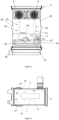
Figure 5 illustrates the top face of the heat exchanger according toFIG. 1 ; -
Figure 6 illustrates an internal side of the heat exchanger according toFIG. 1 ; -
Figure 7 shows a heat exchanger according to another embodiment of the invention. - Identical components or respectively components with the same function are provided with the same reference numbers in the figures.
-
FIG. 1 shows aheat exchanger 1 designed as a water chiller in accordance with an embodiment of the present invention. - The
heat exchanger 1 comprises ahousing 2 and a plurality ofchannel tubes 3 placed in thehousing 2, as shown inFIG. 3 . - Each
channel tube 3 comprises inner channels, in particular inner micro-channels (seeFIG. 4 ) configured to allow a circulation of a first heat transfer fluid within theinner channels 4. The first heat transfer fluid is a refrigerant. - A
fluid flow path 5 for a second heat transfer fluid (which is water in this embodiment of the invention) is formed within thehousing 2 and extends between afluid inlet 8 and afluid outlet 9 located on thehousing 2. Thefluid flow path 5 is illustrated with arrows F1, F2 and F3 (seeFIG. 5 for instance). - The
fluid flow path 5 passes between thetubes 3 to enable heat exchange between the first heat transfer fluid in the micro-channels 4 and the second heat transfer fluid around thetubes 3. - The
heat exchanger 1 comprises amain return area 10 configured to enable a U turn (see arrow F2 onFIG. 5 ) on thefluid flow path 5 of the second heat transfer fluid. - Two
local areas main return area 10 to modify the distribution of the second heat transfer fluid in themain return area 10. - The
fluid flow path 5 has anupstream pass 5a (arrow F1) that is upstream themain return area 10, and adownstream pass 5b (arrow F3) that is downstream themain return area 10. - The
upstream pass 5a corresponds to the fluid flow between thefluid inlet 8 and themain return area 10, and thedownstream pass 5b corresponds to the fluid flow between themain return area 10 and thefluid outlet 9. - The
main return area 10 extends across substantially an entire transversal dimension Dtrans of thefluid flow path 5. - The transversal dimension Dtrans is measured perpendicularly to the
channel tubes 3, and is in particular perpendicular to the upstream anddownstream passes - The
main return area 10 has a transversal dimension Dtrans corresponding to the sum of the transversal dimension of theupstream pass 5a and the transversal dimension of thedownstream pass 5b. - The upstream and
downstream passes - In another embodiment of the invention, the upstream and
downstream passes - The
local areas main return area 10. - Each transversal dimension Dt11, Dt12 of the
local area main return area 10, in particular smaller than 40% or 30% or 20% of the transversal dimension Dtrans of themain return area 10. - The
local areas main return area 10. - In this case, the
main return area 10 and thelocal areas - In another embodiment of the invention as illustrated in
FIG. 7 , thelocal area 11 is separate from themain return area 10. In this case, themain return area 10 and thelocal area 11 are defined as two distinct shapes. - The
main return area 10 has a substantially rectangular shape as illustrated inFIG. 5 . - The
fluid flow path 5 is connected to themain return area 10 so that thefluid flow path 5 reaches themain return area 10 in afirst portion 15 of the rectangular shape and thefluid flow 5 leaves themain return area 10 via asecond portion 16 of the rectangular shape. - The first and
second portions - The fluid U-turn takes place in the rectangular shape.
- The transversal dimension Dtrans of the
main return area 10 corresponds to the long side of the rectangular shape (length) of themain return area 10. - Each
local area main return area 10. In other words, thanks to thelocal areas - The cross-section is bigger at the fluid outlet and/or at the middle of the U-turn to minimize the pressure drop of the second fluid (water).
- In particular, the local area(s) 11, 12 are positioned where the velocity of the second fluid is higher, to increase the cross-section in the U-turn. It enables to decrease the pressure drop.
- If the
local areas main return area 10, eachlocal area
Thelocal area 11 is located adjacent to the middle of themain return area 10. - In case the
main return area 10 has a rectangular shape, thelocal area 11 is placed adjacent to the middle of the long side of the rectangular shape. - If the
local area 12 is omitted, themain return area 10 together with thelocal area 11 define a global shape that is symmetrical in respect to a plane of symmetry PS of theheat exchanger 1. - For instance, this shape is a T-shape. The leg of the T is oriented towards the
fluid inlet 8 andoutlet 9. - If the
local area 12 is present, themain return area 10 together with thelocal areas - The
local area 12 is closer to a lateral side (which is a short side of a rectangle) than an opposite lateral side of themain return area 10. - In other words, the
local area 12 is not positioned at the middle of themain return area 10. - For instance, this shape (
main return area 10 and local area 12) is a L-shape. The smallest branch of the L is oriented towards thefluid inlet 8. - In embodiment of
FIG. 5 , themain return area 10 connects a firstlocal area 11 in its middle and a secondlocal area 12 on a lateral side of themain return area 10. - The
local area 12 is positioned closer to thefluid inlet 8 than thefluid outlet 9 of the second fluid (water). - Each
local area main return area 10. - The
main return area 10 is an embossed area on awall 20 of thehousing 2. Thelocal areas wall 20 of thehousing 2. - The
main return area 10 and thelocal areas - The
fluid inlet 8 andoutlet 9 are positioned on one side of thewall 20 of thehousing 2 and themain return area 10 is positioned on an opposite side of thewall 20. - The
housing 2 comprises aplate 21 that defines awall 20 of thehousing 2. - The
main return area 10 and thelocal areas plate 21, by stamping theplate 21. - The
housing 2 comprises twoopposite walls 20 formed by twoparallel plates 21, one serving as an upper wall and the other as a bottom wall. - Both
plates 21 are provided with themain return area 10 and thelocal areas FIG. 1 and FIG. 2 . - The
channel tubes 3 contact the housing oppositewalls 20 along theirlongitudinal edges 24, as shown inFIG. 6 . - The second fluid leaves the inter-tube space and accomplishes the U-turn in the volume of the
main return area 10 and thelocal areas - A portion of length of the
longitudinal edges 24 of thechannel tubes 3 faces themain return area 10 and thelocal areas - In another embodiment of the invention, only one of the
plates 21 comprise the main return area and the local area and the other plate comprise a main return area without a local area. - The
main return area 10 is also called water box. - The
channel tubes 3 are longitudinally positioned between theinlet 8 andoutlet 9 on one side, and themain return area 10 and thelocal areas - The
heat exchanger 1 comprises twoopposite end manifolds channel tubes 3 are connected at their opposite ends to the end manifolds 30 and 31. -
Manifold 30 comprises adistribution column 33 configured to distribute the refrigerant in thetubes 3, and acollection column 34 configured to collect the refrigerant as it exits thetubes 3. Thedistribution column 33 distributes the refrigerant to a first set ofchannels 4 via slots on a guide plate (not shown). -
Manifold 31, opposite tomanifold 30, is configured to guide the refrigerant between different sets of the micro-channels 4 and to define the return pass. - The
housing 2 further comprisesside plates 40. Theplates manifolds tubes 3 and is designed for glycol water flow within the sealed volume. - The
fluid inlet 8 and thefluid outlet 9 each have atubular fluid connector 44 to ensure a connection with an external coolant circuit. - The
housing 2 is made of plastics or metal.
Claims (13)
- A heat exchanger (1), in particular a chiller, comprising:- a housing (2);- a plurality of channel tubes (3) placed in the housing (2) and comprising inner channels (4), in particular inner micro-channels, configured to allow a circulation of a first heat transfer fluid within the inner channels;- a fluid flow path (5) for a second heat transfer fluid, said fluid flow path being formed within the housing (2) and having a fluid inlet (8) and a fluid outlet (9) located on the housing (2), the fluid flow path (5) passing between the tubes (3) to enable heat exchange between the first heat transfer fluid and the second heat transfer fluid;- a main return area (10) configured to enable a U turn on the fluid flow path (5);- a local area (11, 12) configured to change a distribution of the second heat transfer fluid in the main return area (10).
- A heat exchanger (1) according to claim 1, wherein the main return area (10) extends across an entire transversal dimension (Dtrans) of the fluid flow path (5).
- A heat exchanger (1) according to claim 2, wherein the local area (11, 12) has a transversal dimension (Dt11, Dt12) that is smaller than the transversal dimension (Dtrans) of the main return area (10), in particular the transversal dimension of the local area (11, 12) is smaller than 50% of the transversal dimension of the main return area (10), in particular smaller than 40% or 30% or 20% of the transversal dimension of the main return area (10).
- A heat exchanger (1) according to any of the preceding claims, wherein the local area (11, 12) is connected to the main return area (10).
- A heat exchanger (1) according to any of claims 1 to 3, wherein the local area (11, 12) is separate from the main return area (10).
- A heat exchanger (1) according to claims 4 and 5, wherein at least two local areas are associated with the main return area, with a first local area placed in contact with the main return area and a second local area separate from the main return area.
- A heat exchanger (1) according to any of the preceding claims, wherein the main return area (10) has a substantially rectangular shape, and in particular the fluid flow path (5) is connected to the main return area (10) so that the fluid flow path (5) reaches the main return area (10) in a first portion (15) of the rectangular shape and the fluid flow leaves the main return area (10) via a second portion (16) of the rectangular shape.
- A heat exchanger (1) according to any of the preceding claims, wherein the main return area (10) together with the local area (11, 12) define a global shape that is symmetrical in respect to a plane of symmetry (PS) of the heat exchanger (1).
- A heat exchanger (1) according to any of claims 1 to 7, wherein the main return area (10) together with the local area (11, 12) define a global shape that is asymmetrical.
- A heat exchanger (1) according to any of the preceding claims, wherein the local area (11, 12) is positioned closer to the fluid inlet (8) than the fluid outlet (9) of the second fluid.
- A heat exchanger (1) according to any of the preceding claims, wherein the local area (11, 12) is an embossed area on a wall (20) of the housing (2).
- A heat exchanger (1) according to any of the preceding claims, wherein the fluid inlet (8) and outlet (9) are positioned on one side of a wall (20) of the housing (2) and the main return area (10) is positioned on an opposite side of the wall (20).
- A heat exchanger (1) according to any of the preceding claims, wherein the channel tubes (3) are longitudinally positioned between the inlet (8) and outlet (9) on one side, and the main return area (10) and the local area (11, 12) on the other side.
Priority Applications (2)
| Application Number | Priority Date | Filing Date | Title |
|---|---|---|---|
| EP23215172.0A EP4567366A1 (en) | 2023-12-08 | 2023-12-08 | A heat exchanger, in particular a chiller |
| PCT/EP2024/085034 WO2025120133A1 (en) | 2023-12-08 | 2024-12-06 | A heat exchanger, in particular a chiller |
Applications Claiming Priority (1)
| Application Number | Priority Date | Filing Date | Title |
|---|---|---|---|
| EP23215172.0A EP4567366A1 (en) | 2023-12-08 | 2023-12-08 | A heat exchanger, in particular a chiller |
Publications (1)
| Publication Number | Publication Date |
|---|---|
| EP4567366A1 true EP4567366A1 (en) | 2025-06-11 |
Family
ID=89164442
Family Applications (1)
| Application Number | Title | Priority Date | Filing Date |
|---|---|---|---|
| EP23215172.0A Pending EP4567366A1 (en) | 2023-12-08 | 2023-12-08 | A heat exchanger, in particular a chiller |
Country Status (2)
| Country | Link |
|---|---|
| EP (1) | EP4567366A1 (en) |
| WO (1) | WO2025120133A1 (en) |
Citations (4)
| Publication number | Priority date | Publication date | Assignee | Title |
|---|---|---|---|---|
| GB468013A (en) * | 1936-07-04 | 1937-06-28 | Charles Harold Leach | Improvements in tubular heat exchangers for oil refining apparatus |
| US20140190673A1 (en) * | 2011-06-30 | 2014-07-10 | Valeo Systemes Thermiques | Heat Exchanger, Particularly For A Motor Vehicle |
| US20170336147A1 (en) * | 2016-05-19 | 2017-11-23 | Borgwarner Emissions Systems Spain, S.L.U. | Heat exchange device |
| US20210325118A1 (en) * | 2018-11-30 | 2021-10-21 | Zhejiang Sanhua Automotive Components Co., Ltd. | Heat Exchange Device |
-
2023
- 2023-12-08 EP EP23215172.0A patent/EP4567366A1/en active Pending
-
2024
- 2024-12-06 WO PCT/EP2024/085034 patent/WO2025120133A1/en active Pending
Patent Citations (4)
| Publication number | Priority date | Publication date | Assignee | Title |
|---|---|---|---|---|
| GB468013A (en) * | 1936-07-04 | 1937-06-28 | Charles Harold Leach | Improvements in tubular heat exchangers for oil refining apparatus |
| US20140190673A1 (en) * | 2011-06-30 | 2014-07-10 | Valeo Systemes Thermiques | Heat Exchanger, Particularly For A Motor Vehicle |
| US20170336147A1 (en) * | 2016-05-19 | 2017-11-23 | Borgwarner Emissions Systems Spain, S.L.U. | Heat exchange device |
| US20210325118A1 (en) * | 2018-11-30 | 2021-10-21 | Zhejiang Sanhua Automotive Components Co., Ltd. | Heat Exchange Device |
Also Published As
| Publication number | Publication date |
|---|---|
| WO2025120133A1 (en) | 2025-06-12 |
Similar Documents
| Publication | Publication Date | Title |
|---|---|---|
| US9927158B2 (en) | Refrigeration system with integrated core structure | |
| US7469554B2 (en) | Condenser, in particular for a motor vehicle air conditioning circuit, and circuit comprising same | |
| US4966230A (en) | Serpentine fin, round tube heat exchanger | |
| US5168925A (en) | Heat exchanger | |
| CN101680689B (en) | Heat exchanger | |
| EP2810010B1 (en) | Multiple tube bank heat exchanger assembly and fabrication method | |
| US6823933B2 (en) | Stacked-type, multi-flow heat exchangers | |
| CN103988042A (en) | Plate for heat exchanger and heat exchanger equipped with the plate | |
| US20230168048A1 (en) | Heat exchanger | |
| US20150219409A1 (en) | Heat exchanger utilizing tubular structures having internal flow altering members and external chamber assemblies | |
| EP3872435B1 (en) | A heat exchanger | |
| US6742577B2 (en) | Laminate type evaporator | |
| US6364006B1 (en) | Beaded plate for a heat exchanger and method of making same | |
| KR20100018477A (en) | Cross-counterflow heat exchanger assembly | |
| WO2024001737A1 (en) | Heat exchanger | |
| WO2025120133A1 (en) | A heat exchanger, in particular a chiller | |
| CN216114646U (en) | Heat exchanger | |
| US7650934B2 (en) | Heat exchanger | |
| KR20170122663A (en) | Flat tube for a heat exchanger | |
| JPH0630680U (en) | Stacked evaporator element | |
| CN116182593B (en) | Core structure of multi-pass heat exchanger | |
| CN112219083A (en) | Heat exchanger | |
| US20250012523A1 (en) | Advanced disturbance elements for improving pipe performance | |
| US20050109496A1 (en) | Heat exchanger tubing with connecting member and fins and methods of heat exchange | |
| US20260063373A1 (en) | Tube for a heat exchanger |
Legal Events
| Date | Code | Title | Description |
|---|---|---|---|
| PUAI | Public reference made under article 153(3) epc to a published international application that has entered the european phase |
Free format text: ORIGINAL CODE: 0009012 |
|
| STAA | Information on the status of an ep patent application or granted ep patent |
Free format text: STATUS: THE APPLICATION HAS BEEN PUBLISHED |
|
| AK | Designated contracting states |
Kind code of ref document: A1 Designated state(s): AL AT BE BG CH CY CZ DE DK EE ES FI FR GB GR HR HU IE IS IT LI LT LU LV MC ME MK MT NL NO PL PT RO RS SE SI SK SM TR |
|
| STAA | Information on the status of an ep patent application or granted ep patent |
Free format text: STATUS: REQUEST FOR EXAMINATION WAS MADE |
|
| 17P | Request for examination filed |
Effective date: 20251209 |
|
| GRAP | Despatch of communication of intention to grant a patent |
Free format text: ORIGINAL CODE: EPIDOSNIGR1 |
|
| STAA | Information on the status of an ep patent application or granted ep patent |
Free format text: STATUS: GRANT OF PATENT IS INTENDED |
|
| RIC1 | Information provided on ipc code assigned before grant |
Ipc: F28D 7/16 20060101AFI20260121BHEP Ipc: F28F 9/02 20060101ALI20260121BHEP Ipc: F28F 1/02 20060101ALN20260121BHEP |
|
| INTG | Intention to grant announced |
Effective date: 20260202 |
|
| RAP1 | Party data changed (applicant data changed or rights of an application transferred) |
Owner name: VALEO ELECTRIFICATION |