EP4567343A1 - Unit and heat pump system - Google Patents
Unit and heat pump system Download PDFInfo
- Publication number
- EP4567343A1 EP4567343A1 EP23214565.6A EP23214565A EP4567343A1 EP 4567343 A1 EP4567343 A1 EP 4567343A1 EP 23214565 A EP23214565 A EP 23214565A EP 4567343 A1 EP4567343 A1 EP 4567343A1
- Authority
- EP
- European Patent Office
- Prior art keywords
- vessel
- unit
- condensate
- vessels
- connection
- Prior art date
- Legal status (The legal status is an assumption and is not a legal conclusion. Google has not performed a legal analysis and makes no representation as to the accuracy of the status listed.)
- Pending
Links
Images




Classifications
-
- F—MECHANICAL ENGINEERING; LIGHTING; HEATING; WEAPONS; BLASTING
- F24—HEATING; RANGES; VENTILATING
- F24H—FLUID HEATERS, e.g. WATER OR AIR HEATERS, HAVING HEAT-GENERATING MEANS, e.g. HEAT PUMPS, IN GENERAL
- F24H4/00—Fluid heaters characterised by the use of heat pumps
- F24H4/02—Water heaters
-
- F—MECHANICAL ENGINEERING; LIGHTING; HEATING; WEAPONS; BLASTING
- F24—HEATING; RANGES; VENTILATING
- F24F—AIR-CONDITIONING; AIR-HUMIDIFICATION; VENTILATION; USE OF AIR CURRENTS FOR SCREENING
- F24F1/00—Room units for air-conditioning, e.g. separate or self-contained units or units receiving primary air from a central station
- F24F1/06—Separate outdoor units, e.g. outdoor unit to be linked to a separate room comprising a compressor and a heat exchanger
- F24F1/36—Drip trays for outdoor units
-
- F—MECHANICAL ENGINEERING; LIGHTING; HEATING; WEAPONS; BLASTING
- F24—HEATING; RANGES; VENTILATING
- F24F—AIR-CONDITIONING; AIR-HUMIDIFICATION; VENTILATION; USE OF AIR CURRENTS FOR SCREENING
- F24F13/00—Details common to, or for air-conditioning, air-humidification, ventilation or use of air currents for screening
- F24F13/22—Means for preventing condensation or evacuating condensate
- F24F13/222—Means for preventing condensation or evacuating condensate for evacuating condensate
-
- F—MECHANICAL ENGINEERING; LIGHTING; HEATING; WEAPONS; BLASTING
- F24—HEATING; RANGES; VENTILATING
- F24H—FLUID HEATERS, e.g. WATER OR AIR HEATERS, HAVING HEAT-GENERATING MEANS, e.g. HEAT PUMPS, IN GENERAL
- F24H9/00—Details
- F24H9/02—Casings; Cover lids; Ornamental panels
Definitions
- the present invention relates to a unit for a heat pump system and a heat pump system comprising the unit.
- Air circulating around or along a heat pump inside a heat pump unit may be humid and generally differs from the temperature of the fluid circulating in the pipes/circuits in the heat pump unit.
- the fluid is refrigerant in the case of refrigerant circuits and heat pump components such as a battery exchanger, and the fluid is water in the case of hydraulic circuits. If the ambient air circulating around the pipes is warmer than the fluid circulating in the pipe, the water in the ambient air condenses at the outer surface of the pipe (which has basically/roughly the same temperature as the fluid inside the pipe). This situation occurs, for example, at hydraulic pipes or other hydraulic entities when the heat pump unit is in cooling mode or in the refrigerant circuit near the evaporator. It may be desired to avoid an undefined distribution of water or water stagnation which may lead to corrosion, overweight, water leakage to the installation site, sanitary/hygienic issues or electric short-circuits.
- a condensate tray (vessel) is often positioned underneath the pipes or other entities that are likely to exhibit condensate, and a drain hole is provided at the bottom of the condensate tray.
- the present invention is directed to the unit of claim 1, comprising (hydraulic) elements (fluidly) connected to a hydraulic circuit, a first vessel for collecting condensate condensed inside the unit and at least partially located below/under at least one hydraulic element, a second vessel collecting condensate condensed inside the unit, and a housing housing the first and second vessels, wherein the second vessel is at least partially located lower than the first vessel, when the unit is installed on site, and the first and second vessels are directly or indirectly in fluid communication at least when a predetermined level of condensate received by the first vessel has been reached, and the unit is configured such that condensate drains from the first to the second vessel.
- Condensate refers to water which has resulted from (relatively humid and/or warmer) air condensing on (colder) entities of the unit, in particular on the outer side of the hydraulic elements. It is not excluded that water which has not condensed on entities of the unit, but which has another "origin" is collected by the vessels. For example, it is conceivable that water resulting from a leaking in an entity of the unit or from a cleaning operation is collected by the first and second vessels.
- hydraulic entities may be pumps, pipes, pipe fittings, sensors, flow meters etc., which are installed in the hydraulic circuit of the unit.
- the hydraulic circuit may be seen as a non-refrigerant circuit transporting a water-based fluid, preferably primary water, which is thermally connected (indirectly or directly) to the refrigerant circuit.
- the hydraulic circuit is thermally connected, for further transport of heat/cooling energy, to heat exchangers, such as heat emitters (radiators, underfloor heating) and/or domestic hot water exchangers.
- the vessel in terms of claim 1 represents a condensate vessel, i.e. a vessel for collection of condensate, and may be referred to as compartment, tray, dry pan, receptacle, basin and/or container.
- the vessel may be basically open or partially closed.
- the vessels are configured to collect condensate by capturing water droplets falling down from entities located above the vessels or water rinsing along entities which are located higher than the vessel, possibly adjacent the vessel, so that water/condensate is guided to the vessel, by gravity.
- a vessel may protect parts from exposure to condensate (e.g. parts below a vessel or parts outside the unit), a vessel extending in the horizontal direction, when the unit is installed on site, and allowing for deliberate guidance and handling of condensate.
- the first and second vessels may be in fluid communication to the effect that condensate is immediately discharged from the first to the second vessel, i.e. without a predetermined amount of condensate having to accumulate in the first vessel.
- the collection of condensate corresponds to the capturing of the condensate and "forwarding" of the condensate to the second vessel.
- the first and second vessels may be in fluid communication to the effect that only once a predetermined volume has been accommodated/reached in the first vessel, an overflow of condensate occurs from the first to the second vessel.
- the idea underlying the present invention is to allow for drainage of condensate from a first vessel to a second vessel inside the unit. This may avoid the need for a drainage of the first vessel to the outside of the unit.
- the first vessel may be free of a direct drainage to the outside of the unit. Rather, a common outlet for drainage of the condensate collected by first and second vessels may be provided at the second vessel.
- the first and second vessels may cooperate to the effect that condensate flows from the first to the second vessel and in particular in that they share an outlet at the second vessel.
- the first vessel may have an indirect drainage to the outside only. As the first vessel drains condensate to second vessel, the first vessel does not need to have a drainage to the outside of the unit. This may simplify installation of a unit.
- the second vessel may only be configured to collect condensate from the first vessel. However, it is preferable that the second vessel is configured to collect condensate from the first vessel as well as "fresh" condensate, i.e. condensed inside the unit at at least one hydraulic element, wherein the second vessel is at least partially located lower than the at least one hydraulic element, when the unit is installed on site.
- the second vessel has an outlet for drainage of condensate to the outside of the unit, optionally for connection to a drain pipe.
- the second vessel may have a drainage or outlet, e.g. a drain pipe.
- a unit according to the present invention may allow for a more compact design, as less space may be needed.
- the first and second vessels are in fluid communication, only one single drainage, namely a (single) common drainage at the second vessel, to the outside may be needed. This may reduce installation efforts and costs. Also, this may reduce the number of connections to be made, which in turn may reduce the number of fittings, parts and work required for these connections.
- Omitting further (outside) drainage pipes is preferable, as the number of high-quality pipes which are needed for external connection may be reduced.
- tubes are on the outside of the unit, they need to be strong and watertight. To the contrary, tubes connecting the vessels inside a unit may already be protected by the unit casing, so tubes with no special reinforcement may be used.
- pumps may be needed for drainage.
- having a single drain pipe which only entails a single pump to evacuate the condensate from various vessels inside the unit may be particularly preferable.
- the present invention may allow for more freedom and versatility in positioning of entities inside the unit, as a modular design is conceivable or the use of at least two fluidly connected vessels is less limiting as to the architecture of the unit.
- the respective vessel may have an opening which is lower than at least a part of the remaining respective vessel.
- having an opening at the lowest point of the respective vessel may allow for complete emptying of the respective vessel by drainage.
- the opening does not need to be in the lowest point.
- the opening is, if not in the bottom, in the sidewall at the lowest possible point/level of the vessel with regard to technical feasibility and consideration of assembly constraints with other parts.
- the opening of the second vessel corresponds to the outlet of the second vessel.
- the opening/outlet of the first or second vessel may have a surface area of at least 15 mm 2 , preferably 50 mm 2 , more preferably 80 mm 2 .
- the second vessel is located at the bottom of the unit and/or the outlet of the second vessel is lower than any hydraulic entity of the unit.
- the first vessel defines a first volume
- the second vessel defines a second volume
- the second volume is larger than the first volume
- the first volume is at least 200 ml, preferably at least 400 ml
- the second volume is at least 500 ml, preferably at least 1000 ml.
- the volume defined by the respective vessel refers to the amount of condensate the respective vessel is configured to accumulate/store. This may avoid overflow of the second vessel. If the second volume is larger than the first volume, the second vessel is specifically configured to collect condensate not only being drained from the first vessel, but also condensate directly dropping/rinsing into the second vessel.
- the first vessel is at least partially arranged above the second vessel in the unit such that the unit is configured such that condensate flows downwards (runs downwards), in particular falls vertically, optionally from an opening in the first vessel, from the first vessel into the second vessel.
- the opening in the first vessel may be arranged above a part of the second vessel. In this case, no horizontal path may be necessary for the condensate when draining from the first vessel to the second vessel. Rather, a direct vertical drainage of condensate from the opening of the first vessel into the second vessel is possible.
- the unit comprises at least one connection directly or indirectly fluidly connecting the first and second vessels and at least partially directing condensate from the first vessel to the second vessel.
- the connection may be seen as an intermediate section joining the first and second vessels, at least partially.
- the connection is configured to guide condensate from the first vessel to the second vessel, at least when a predetermined level of condensate is received by the first vessel.
- the connection may help to guide the water and/or to at least partially surround the condensate during falling, which may avoid splashing, undesired escape of fluid and/or noise. More than one connection may be provided to connect the first and second vessels.
- the at least one connection comprises a chute, such as a tube or half-tube. This may support efficient guidance of condensate, while avoiding undesired splashing.
- connection is at least in parts and/or when seen in total inclined at an angle ⁇ between 0° and 15° relative to the vertical, when the unit is installed on site. If the angle ⁇ is 0°, the connection is a vertical connection between the first and second vessels. Specifically, the total difference in height between the first and second vessels (as to the condensate accommodation), i.e. the vertical difference, and the total horizontal difference between the opening in the first vessel and the point where the condensate hits the second vessel may define the inclination. The inclination allows for an appropriate slope to facilitate drainage of the condensate from the first vessel to the second vessel, while saving space.
- the first and/or second vessel is at least in parts inclined relative to the horizontal so as to direct a flow/drain of condensate, optionally a vertical difference between opposite ends of inclined parts of the respective vessel being at least 5 mm, preferably at least 10 mm.
- parts of the bottom of the first and/or second vessel are inclined relative to the horizontal, this configures the first and/or second vessel to direct a flow or drain of condensate to the opening (or outlet, in case of the second vessel).
- a part may be inclined from its end joining a wall of the vessel to its opposite end at the opening.
- a vessel may comprise a plurality of such inclined parts, which have a common lower region and a common higher region.
- the bottom may, as such, consist of a plurality of planes, which are inclined relative to each other.
- the first and/or second vessel comprises one or more cavities for at least partially embracing one or more hydraulic elements to hold the elements in place. If the first and/or second vessel has cavities for holding hydraulic elements, the space within the unit can efficiently be used. This allows to further minimize the unit and to save space.
- the first vessel has a surface area between 25 000 and 150 000 mm 2
- the second vessel has a surface area of between 25 000 and 150 000 mm 2 , in a top view when the unit is installed on site. This may allow for appropriate coverage as to water collection in the unit.
- the first vessel has at least one opening, optionally the opening being a hole in the bottom of the first vessel and/or an opening in a wall of the first vessel.
- the opening is located in a lower section of the wall, in particular in the lower half of the wall so as to limit the amount of condensate that is retained by the first vessel.
- the hole in the bottom of the first vessel is at the lowest point of the bottom or at a point which is less than 10 mm, preferably less than 5 mm higher than the lowest point of the bottom, when the unit is installed on site. The same applied for an opening and the bottom of the second vessel.
- the opening has a surface area of at least 15 mm 2 , preferably 50 mm 2 , more preferably 80 mm 2 , and/or is, if dependent on claim 6, connectable to the connection.
- the first and/or second vessels are made of plastic, preferably foam, more preferably EPP (Expanded Polyethylene), and/or are made by injection molding, thermoforming, bending, stamping or 3D-printing.
- EPP Expanded Polyethylene
- EPP may hold water and also allow for mechanical stability, to e.g. fix entities.
- first and second vessels and/or the connection are a single piece or separate pieces.
- first vessel and the connection, or the connection and the second vessel form a single piece.
- Providing a single piece-configuration instead of multiple pieces which need to be joined subsequently, may reduce the risk of leaks arising at joints.
- the one piece-configuration at least for some of the entities of the unit, may improve the reliability of the unit.
- Advantages for embodiments having separate vessels may be that they are mountable and dismountable from each other so it facilitates the (global) maintenance because only the needed sector may be removed to have access to the part(s) behind. Further, lower tool investment is conceivable because of a few small molds instead of a big one which could be bigger than the several small ones in total.
- first and second vessels in addition to first and second vessels, further vessels may be provided. Accordingly, the disclosure in connection with the first and second vessels equally applies to a plurality of vessels, in particular a plurality of vessels, wherein one vessel corresponds to the second vessel in terms of claim 1 and the remaining vessels correspond a first vessel of claim 1.
- the second vessel may represent the lowest vessel, wherein the first and (a) further vessel(s) are positioned, in particular at different heights, higher than the second vessel.
- at least one additional vessel for collecting condensate and connected either in series or in parallel to the first and/or second vessels may be provided.
- one or more hydraulic elements may be thermally insulated relative to ambient air, i.e. having at least partially a thermally insulating layer on the outside.
- a hydraulic element may comprise at least in parts of its outer surface a thermally insulating layer, e.g. made of polystyrene or another foam. This may help to reduce the occurrence of condensate as such. However, positioning of insulation is often difficult and insulation may not be possible for the entirety of entities.
- the invention in general, refers to any unit of a heat pump system, including heat pump units, such as ground source (water)- or air source-heat pump units.
- the units may be indoor or outdoor units.
- the units may be split units or monobloc units.
- the heat pump system may be configured to heat air or water (of a closed loop or of an open loop, such as domestic hot water).
- a unit of the invention may, but does not have to include (at least a part of the) refrigerant circuit.
- a unit of the invention may only have elements which are part of a hydraulic circuit, i.e. at least a part of a hydraulic circuit.
- the unit may optionally also have elements which are part of the refrigerant circuit, i.e.
- the unit may be an indoor unit associated with a monobloc outdoor unit, meaning that the outdoor unit represents the heat pump unit comprising the entire refrigerant circuit and warms primary water which flows to the indoor unit.
- the invention also relates to a heat pump system comprising a unit of the present invention, the unit further including a compressor, an expansion element, two heat exchangers (one being the evaporator and the other being the condenser) and a refrigerant circuit with refrigerant flowing between these components.
- the heat pump system may comprise a unit of the present invention being an indoor unit and may further comprise a (separate) heat pump unit.
- the system may include a compressor, an expansion element and two heat exchangers, which are part of a refrigerant circuit, wherein the system is configured such that the refrigerant circuit exchanges heat/cooling energy with the hydraulic circuit.
- the unit of the invention is comprised in a ground source or geothermal heat pump system.
- Figure 1 shows a unit 1 with parts of it removed, so that the interior of the unit 1 is visible.
- figure 1 shows a first vessel 2 and a second vessel 3, wherein the second vessel 3 is located lower than the first vessel 2.
- the first vessel 2 is configured to collect condensate (water) condensed inside the unit 1.
- the second vessel 3 is configured to collect condensate condensed inside the unit 1.
- Part of the housing 6 housing the first 2 and second 3 vessels is shown in figure 1(a) , in particular a frame of the housing 6.
- Figure (1b ) shows a view in which parts of the frame of the housing 6 and some hydraulic parts are removed for better visibility of the vessels and, in addition to the first vessel 2 and the second vessel 3, hydraulic elements, in particular pipings 11 are indicated.
- the hydraulic piping 11 conducts fluid which is typically cooler than the ambient air, so that water in the air condenses at the hydraulic pipes 11.
- the first vessel 2 comprises a plurality of cavities 10 which at least partially embrace the hydraulic pipes 11, so as to hold the pipes 11 in place.
- the second vessel 3 is basically located at a bottom 9 of the unit 1.
- Figure 1(b) further shows a connection 4 which fluidly connects the first 2 and second 3 vessels with each other.
- the connection 4 is configured to direct condensate from the first vessel 2 to the second vessel 3.
- Figure 1(c) shows a cross-sectional view, from which it is evident that the connection 4 is basically a vertical connection, having an angle of 0° relative to the vertical direction V. As such, an outer part of the first vessel 2 is arranged above the second vessel 3 so that condensate may drain vertically from the first vessel 2 to the second vessel 3 through the connection 4.
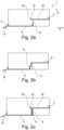
- Figure 2(a) schematically shows an embodiment in which the first vessel 2 has an opening 12 in the bottom 16 of the vessel, wherein the condensate 5 drops vertically and freely, i.e. without connection 4, downwards onto and in the second vessel 3.
- the first vessel 2 has a wall 15 which helps to collect water and prevents water from draining sideways.
- the first vessel 2 is configured such that no predetermined level of condensate is to be accommodated in the first vessel 2 before collected condensate drains to the second vessel 3.
- Figure 2(a) further shows a drain pipe 8 at the second vessel 3, which drain pipe 8 is connected to an outlet 7 for drainage of condensate to the outside of the unit 1.
- the outlet 7 of the second vessel 3 is located in a wall 15 of the vessel 3, so that condensate accumulates up to a specific level before overflowing and passing through the outlet 7.
- the condensate 5 drains from the first vessel 2 to the second vessel 3, by dropping or rinsing due to gravity.
- Figure 2(b) shows another embodiment, in which the connection 4 is inclined and the condensate 5 is guided at least in part by the connection 4 in the horizontal direction H, when draining from the first vessel 2 to the second vessel 3.
- the first vessel 2 has no closed vessel wall 15, and the condensate 5 may fall from the first vessel 2 due to lack of sideways retaining means.
- Figure 2(c) reflects another embodiment having a connection 4 which surrounds the condensate 5 when vertically falling down from the first vessel 2 through the opening 12 of the first vessel 2.
- Figure 2(d) shows an embodiment in which the first and second vessels 2, 3 are at least partially closed/covered in that they comprise a cover 17 which partially covers the respective vessel 2, 3.
- An opening 12 is formed in the first vessel 2 sideways and at the bottom of the first vessel 2.
- the vertical connection 4 connects to an aperture 18 in the cover 17 of the second vessel 3, so as to allow for fluid communication between the first and second vessels 2, 3.
- Figure 3(a) shows a first vessel 2 of the invention in detail, wherein the bottom 16 of the first vessel 2 comprises a groove 14 guiding condensate towards the opening 12 of the first vessel 2.
- the bottom 16 of the first vessel 2 consists of three bottom parts, which are each inclined relative to each other and relative to the horizontal H.
- the three parts of the bottom 16 have a common lower region 19 and a common upper region 20, namely the edge at the walls 15 of the first vessel 2.
- Such configuration with a groove 14 and/or inclined parts of the bottom 16 may be realized in any first and/or second vessel 2, 3.
- Figure 3(b) shows an expanded view of Fig. 3(a) and in particular a groove 14 running towards the opening 12 in the first vessel 3, along the common lower region 19.
- Figure 3(c) shows a cross-sectional view of the embodiment of figure 3(a) , from which it is evident that parts of the bottom 16 of the first vessel 2 are inclined relative to the horizontal direction H by the angle ⁇ .
- the total difference in the vertical direction V is dV and may be about 10 mm.
- the inclination is provided such that it supports flow of the condensate towards the opening 12 of the first vessel 2.
- Such configuration with an inclined the bottom 16 may be realized in any first and/or second vessel 2, 3.
- Figure 4 shows a connection 4 having a number of fastening cavities 10 and allowing for vertical guidance of condensate 5.
- Figure 5 shows a second vessel 3, wherein an outlet 7 is provided at a corner of the wall 15 of the vessel 3.
- the bottom 16 of the second vessel 3 is inclined relative to the upper part of the second vessel 3 and running towards a lower part at the outlet 7.
- Figure 6(a) schematically shows an arrangement of a plurality of vessels in a unit 1 of the invention.
- an additional vessel 13 namely a third vessel, is provided in addition to the first vessel 2 and the second vessel 3, to which the drain pipe 8 is connected.
- the third vessel 13 is connected in parallel to the first vessel 2, wherein each of the first vessel 2 and the additional vessel 13 connects via a connection 4 to the second vessel 3.
- Both the first vessel 2 and the additional vessel 13 are positioned higher than the second vessel 3.
- Figure 6(b) shows an alternative arrangement of three vessels, wherein the first vessel 2 is located higher than the third vessel 13, wherein the third vessel 13 is located higher than the second vessel 3.
- the first, third, and second vessels 2, 13, 3 are connected in series via corresponding connections 4. It is conceivable that, in addition to the additional vessel 13, further additional vessels are provided.
- each of these entities represents a separate entity. These separate entities need to be fluidly connected and joined afterwards.
- the first and second vessels 2, 3, and/or the connection 4 may be formed as a single piece.
- the first 2 and second 3 vessels are made of plastics.
- the connection 4 may be made of plastics.
- the volume which can be accommodated by the first vessel 2 may be smaller than the volume of condensate that can be accommodated by the second vessel 3. It is also conceivable that e.g. the first vessel 2 does not accommodate condensate at all, but only collects and guides condensate away from the first vessel 2. In this case, the actual volume accommodated by the first vessel 2 may be regarded as zero.
Landscapes
- Engineering & Computer Science (AREA)
- Chemical & Material Sciences (AREA)
- Combustion & Propulsion (AREA)
- Mechanical Engineering (AREA)
- General Engineering & Computer Science (AREA)
- Physics & Mathematics (AREA)
- Thermal Sciences (AREA)
- Sewage (AREA)
Abstract
The invention refers to a unit comprising hydraulic elements connected to a hydraulic circuit, a first vessel configured to collect condensate condensed inside the unit at at least one hydraulic element, and at least partially located lower than the at least one hydraulic element, when the unit is installed on site, a second vessel configured to collect condensate condensed inside the unit, and a housing housing the first and second vessels, wherein the second vessel is at least partially located lower than the first vessel, when the unit is installed on site, and the first and second vessels are directly or indirectly in fluid communication at least when a predetermined level of condensate received by the first vessel has been reached, and the unit is configured such that condensate drains from the first to the second vessel.
Description
- The present invention relates to a unit for a heat pump system and a heat pump system comprising the unit.
- Air circulating around or along a heat pump inside a heat pump unit (ambient air) may be humid and generally differs from the temperature of the fluid circulating in the pipes/circuits in the heat pump unit. For example, the fluid is refrigerant in the case of refrigerant circuits and heat pump components such as a battery exchanger, and the fluid is water in the case of hydraulic circuits. If the ambient air circulating around the pipes is warmer than the fluid circulating in the pipe, the water in the ambient air condenses at the outer surface of the pipe (which has basically/roughly the same temperature as the fluid inside the pipe). This situation occurs, for example, at hydraulic pipes or other hydraulic entities when the heat pump unit is in cooling mode or in the refrigerant circuit near the evaporator. It may be desired to avoid an undefined distribution of water or water stagnation which may lead to corrosion, overweight, water leakage to the installation site, sanitary/hygienic issues or electric short-circuits.
- In these cases, a condensate tray (vessel) is often positioned underneath the pipes or other entities that are likely to exhibit condensate, and a drain hole is provided at the bottom of the condensate tray.
- It is desired to further improve units of a heat pump system with respect to collection of condensate.
- The present invention is directed to the unit of claim 1, comprising (hydraulic) elements (fluidly) connected to a hydraulic circuit, a first vessel for collecting condensate condensed inside the unit and at least partially located below/under at least one hydraulic element, a second vessel collecting condensate condensed inside the unit, and a housing housing the first and second vessels, wherein the second vessel is at least partially located lower than the first vessel, when the unit is installed on site, and the first and second vessels are directly or indirectly in fluid communication at least when a predetermined level of condensate received by the first vessel has been reached, and the unit is configured such that condensate drains from the first to the second vessel.
- Condensate refers to water which has resulted from (relatively humid and/or warmer) air condensing on (colder) entities of the unit, in particular on the outer side of the hydraulic elements. It is not excluded that water which has not condensed on entities of the unit, but which has another "origin" is collected by the vessels. For example, it is conceivable that water resulting from a leaking in an entity of the unit or from a cleaning operation is collected by the first and second vessels.
- Generally, hydraulic entities may be pumps, pipes, pipe fittings, sensors, flow meters etc., which are installed in the hydraulic circuit of the unit. The hydraulic circuit may be seen as a non-refrigerant circuit transporting a water-based fluid, preferably primary water, which is thermally connected (indirectly or directly) to the refrigerant circuit. The hydraulic circuit is thermally connected, for further transport of heat/cooling energy, to heat exchangers, such as heat emitters (radiators, underfloor heating) and/or domestic hot water exchangers.
- The vessel in terms of claim 1 represents a condensate vessel, i.e. a vessel for collection of condensate, and may be referred to as compartment, tray, dry pan, receptacle, basin and/or container.
- The vessel may be basically open or partially closed. The vessels are configured to collect condensate by capturing water droplets falling down from entities located above the vessels or water rinsing along entities which are located higher than the vessel, possibly adjacent the vessel, so that water/condensate is guided to the vessel, by gravity. In other words, a vessel may protect parts from exposure to condensate (e.g. parts below a vessel or parts outside the unit), a vessel extending in the horizontal direction, when the unit is installed on site, and allowing for deliberate guidance and handling of condensate.
- The first and second vessels may be in fluid communication to the effect that condensate is immediately discharged from the first to the second vessel, i.e. without a predetermined amount of condensate having to accumulate in the first vessel. In this case, the collection of condensate corresponds to the capturing of the condensate and "forwarding" of the condensate to the second vessel. Alternatively, the first and second vessels may be in fluid communication to the effect that only once a predetermined volume has been accommodated/reached in the first vessel, an overflow of condensate occurs from the first to the second vessel.
- The idea underlying the present invention is to allow for drainage of condensate from a first vessel to a second vessel inside the unit. This may avoid the need for a drainage of the first vessel to the outside of the unit. For example, the first vessel may be free of a direct drainage to the outside of the unit. Rather, a common outlet for drainage of the condensate collected by first and second vessels may be provided at the second vessel. In other words, the first and second vessels may cooperate to the effect that condensate flows from the first to the second vessel and in particular in that they share an outlet at the second vessel. As such, the first vessel may have an indirect drainage to the outside only. As the first vessel drains condensate to second vessel, the first vessel does not need to have a drainage to the outside of the unit. This may simplify installation of a unit.
- The second vessel may only be configured to collect condensate from the first vessel. However, it is preferable that the second vessel is configured to collect condensate from the first vessel as well as "fresh" condensate, i.e. condensed inside the unit at at least one hydraulic element, wherein the second vessel is at least partially located lower than the at least one hydraulic element, when the unit is installed on site.
- Optionally, the second vessel has an outlet for drainage of condensate to the outside of the unit, optionally for connection to a drain pipe. In this optional case, only the second vessel may have a drainage or outlet, e.g. a drain pipe.
- A unit according to the present invention may allow for a more compact design, as less space may be needed. In particular, as the first and second vessels are in fluid communication, only one single drainage, namely a (single) common drainage at the second vessel, to the outside may be needed. This may reduce installation efforts and costs. Also, this may reduce the number of connections to be made, which in turn may reduce the number of fittings, parts and work required for these connections.
- Omitting further (outside) drainage pipes (but using only a common drainage at the second vessel) is preferable, as the number of high-quality pipes which are needed for external connection may be reduced. When tubes are on the outside of the unit, they need to be strong and watertight. To the contrary, tubes connecting the vessels inside a unit may already be protected by the unit casing, so tubes with no special reinforcement may be used.
- In some installations, pumps may be needed for drainage. For example, it may be necessary to provide solutions for collecting condensate and draining it into the waste water pipes at the installation site which may be above the unit. This requires the installation of a pump for lifting of the condensate. In this case, having a single drain pipe which only entails a single pump to evacuate the condensate from various vessels inside the unit, may be particularly preferable.
- The present invention may allow for more freedom and versatility in positioning of entities inside the unit, as a modular design is conceivable or the use of at least two fluidly connected vessels is less limiting as to the architecture of the unit.
- Optionally, at a lower region of the first and/or second vessels, the respective vessel may have an opening which is lower than at least a part of the remaining respective vessel. For example, having an opening at the lowest point of the respective vessel may allow for complete emptying of the respective vessel by drainage. However, the opening does not need to be in the lowest point. It is also appropriate (but possibly less preferable) to have an opening at a region/point which is lower than at least a part of the respective vessel, which means that a level of accumulated condensate below the opening (a retained volume of condensate) may remain in the respective vessel. However, preferably, the opening is, if not in the bottom, in the sidewall at the lowest possible point/level of the vessel with regard to technical feasibility and consideration of assembly constraints with other parts. Optionally, the opening of the second vessel corresponds to the outlet of the second vessel.
- Further optionally, the opening/outlet of the first or second vessel may have a surface area of at least 15 mm2, preferably 50 mm2, more preferably 80 mm2.
- Optionally, the second vessel is located at the bottom of the unit and/or the outlet of the second vessel is lower than any hydraulic entity of the unit. By providing the second vessel at such location, an attempt is made to collect condensate at any location within the unit, namely by providing a lowest collector.
- Optionally, the first vessel defines a first volume, and the second vessel defines a second volume, and wherein the second volume is larger than the first volume, and/or the first volume is at least 200 ml, preferably at least 400 ml, and/or the second volume is at least 500 ml, preferably at least 1000 ml. The volume defined by the respective vessel refers to the amount of condensate the respective vessel is configured to accumulate/store. This may avoid overflow of the second vessel. If the second volume is larger than the first volume, the second vessel is specifically configured to collect condensate not only being drained from the first vessel, but also condensate directly dropping/rinsing into the second vessel.
- Optionally, the first vessel is at least partially arranged above the second vessel in the unit such that the unit is configured such that condensate flows downwards (runs downwards), in particular falls vertically, optionally from an opening in the first vessel, from the first vessel into the second vessel. Specifically, the opening in the first vessel may be arranged above a part of the second vessel. In this case, no horizontal path may be necessary for the condensate when draining from the first vessel to the second vessel. Rather, a direct vertical drainage of condensate from the opening of the first vessel into the second vessel is possible.
- Optionally, the unit comprises at least one connection directly or indirectly fluidly connecting the first and second vessels and at least partially directing condensate from the first vessel to the second vessel. The connection may be seen as an intermediate section joining the first and second vessels, at least partially. The connection is configured to guide condensate from the first vessel to the second vessel, at least when a predetermined level of condensate is received by the first vessel. The connection may help to guide the water and/or to at least partially surround the condensate during falling, which may avoid splashing, undesired escape of fluid and/or noise. More than one connection may be provided to connect the first and second vessels.
- Further optionally, the at least one connection comprises a chute, such as a tube or half-tube. This may support efficient guidance of condensate, while avoiding undesired splashing.
- Optionally, the connection is at least in parts and/or when seen in total inclined at an angle α between 0° and 15° relative to the vertical, when the unit is installed on site. If the angle α is 0°, the connection is a vertical connection between the first and second vessels. Specifically, the total difference in height between the first and second vessels (as to the condensate accommodation), i.e. the vertical difference, and the total horizontal difference between the opening in the first vessel and the point where the condensate hits the second vessel may define the inclination. The inclination allows for an appropriate slope to facilitate drainage of the condensate from the first vessel to the second vessel, while saving space.
- Optionally, the first and/or second vessel is at least in parts inclined relative to the horizontal so as to direct a flow/drain of condensate, optionally a vertical difference between opposite ends of inclined parts of the respective vessel being at least 5 mm, preferably at least 10 mm. If parts of the bottom of the first and/or second vessel are inclined relative to the horizontal, this configures the first and/or second vessel to direct a flow or drain of condensate to the opening (or outlet, in case of the second vessel). For example, a part may be inclined from its end joining a wall of the vessel to its opposite end at the opening. A vessel may comprise a plurality of such inclined parts, which have a common lower region and a common higher region. The bottom may, as such, consist of a plurality of planes, which are inclined relative to each other.
- Optionally, the first and/or second vessel comprises one or more cavities for at least partially embracing one or more hydraulic elements to hold the elements in place. If the first and/or second vessel has cavities for holding hydraulic elements, the space within the unit can efficiently be used. This allows to further minimize the unit and to save space.
- Optionally, the first vessel has a surface area between 25 000 and 150 000 mm2, and/or the second vessel has a surface area of between 25 000 and 150 000 mm2, in a top view when the unit is installed on site. This may allow for appropriate coverage as to water collection in the unit.
- Optionally, the first vessel has at least one opening, optionally the opening being a hole in the bottom of the first vessel and/or an opening in a wall of the first vessel. Preferably, the opening is located in a lower section of the wall, in particular in the lower half of the wall so as to limit the amount of condensate that is retained by the first vessel. Preferably, the hole in the bottom of the first vessel is at the lowest point of the bottom or at a point which is less than 10 mm, preferably less than 5 mm higher than the lowest point of the bottom, when the unit is installed on site. The same applied for an opening and the bottom of the second vessel.
- Further optionally, the opening has a surface area of at least 15 mm2, preferably 50 mm2, more preferably 80 mm2, and/or is, if dependent on
claim 6, connectable to the connection. - Optionally, the first and/or second vessels are made of plastic, preferably foam, more preferably EPP (Expanded Polyethylene), and/or are made by injection molding, thermoforming, bending, stamping or 3D-printing. This allows for simple and efficient manufacture of the vessels and helps to reduce the overall weight of the unit. In particular, EPP may hold water and also allow for mechanical stability, to e.g. fix entities.
- Optionally, the first and second vessels and/or the connection are a single piece or separate pieces. Further optionally, the first vessel and the connection, or the connection and the second vessel form a single piece. Providing a single piece-configuration instead of multiple pieces which need to be joined subsequently, may reduce the risk of leaks arising at joints. As such, the one piece-configuration, at least for some of the entities of the unit, may improve the reliability of the unit. Advantages for embodiments having separate vessels may be that they are mountable and dismountable from each other so it facilitates the (global) maintenance because only the needed sector may be removed to have access to the part(s) behind. Further, lower tool investment is conceivable because of a few small molds instead of a big one which could be bigger than the several small ones in total.
- In a unit of the invention, in addition to first and second vessels, further vessels may be provided. Accordingly, the disclosure in connection with the first and second vessels equally applies to a plurality of vessels, in particular a plurality of vessels, wherein one vessel corresponds to the second vessel in terms of claim 1 and the remaining vessels correspond a first vessel of claim 1. In other words, the second vessel may represent the lowest vessel, wherein the first and (a) further vessel(s) are positioned, in particular at different heights, higher than the second vessel. Accordingly and optionally, in addition to the first and second vessels, at least one additional vessel for collecting condensate and connected either in series or in parallel to the first and/or second vessels may be provided.
- Optionally, one or more hydraulic elements may be thermally insulated relative to ambient air, i.e. having at least partially a thermally insulating layer on the outside. In other words, a hydraulic element may comprise at least in parts of its outer surface a thermally insulating layer, e.g. made of polystyrene or another foam. This may help to reduce the occurrence of condensate as such. However, positioning of insulation is often difficult and insulation may not be possible for the entirety of entities.
- The invention, in general, refers to any unit of a heat pump system, including heat pump units, such as ground source (water)- or air source-heat pump units. The units may be indoor or outdoor units. The units may be split units or monobloc units. The heat pump system may be configured to heat air or water (of a closed loop or of an open loop, such as domestic hot water). A unit of the invention may, but does not have to include (at least a part of the) refrigerant circuit. In other words, a unit of the invention may only have elements which are part of a hydraulic circuit, i.e. at least a part of a hydraulic circuit. The unit may optionally also have elements which are part of the refrigerant circuit, i.e. at least a part of the refrigerant circuit. For example, the unit may be an indoor unit associated with a monobloc outdoor unit, meaning that the outdoor unit represents the heat pump unit comprising the entire refrigerant circuit and warms primary water which flows to the indoor unit.
- The invention also relates to a heat pump system comprising a unit of the present invention, the unit further including a compressor, an expansion element, two heat exchangers (one being the evaporator and the other being the condenser) and a refrigerant circuit with refrigerant flowing between these components. Alternatively, the heat pump system may comprise a unit of the present invention being an indoor unit and may further comprise a (separate) heat pump unit. The system may include a compressor, an expansion element and two heat exchangers, which are part of a refrigerant circuit, wherein the system is configured such that the refrigerant circuit exchanges heat/cooling energy with the hydraulic circuit.
- Preferably, the unit of the invention is comprised in a ground source or geothermal heat pump system.
- Detailed embodiments and further advantages and features related to the present invention are described in the following, wherein these examples shall not be regarded as limiting the invention.
-
- Fig. 1
- shows a unit of the invention, wherein
Fig. 1(a) is a perspective view with some entities removed,Fig. 1(b) is a perspective view with further entities removed, andFig. 1(c) is a cross-sectional view based onFig. 1(b) . - Fig. 2
- schematically shows first and second vessels inside a unit of the invention, wherein
Fig. 2(a) is a schematic sectional view of a first embodiment,Fig. 2(b) is a schematic sectional view of a second embodiment,Fig. 2(c) is a schematic sectional view of a third embodiment, andFig. 2(d) is a schematic sectional view of a fourth embodiment. - Fig. 3
- shows a first vessel of the invention, wherein
Fig. 3(a) is a perspective view,Fig. 3(b) is a top view, andFig. 3(c) is a cross-sectional view. - Fig. 4
- shows a connection of the invention in a perspective view.
- Fig. 5
- shows a second vessel of the invention in a perspective view.
- Fig. 6
- schematically shows vessels inside a unit of the invention, wherein
Fig. 6(a) is a schematic sectional view of a first embodiment, andFig. 6(b) is a schematic sectional view of a second embodiment. -
Figure 1 shows a unit 1 with parts of it removed, so that the interior of the unit 1 is visible. Specifically,figure 1 shows afirst vessel 2 and asecond vessel 3, wherein thesecond vessel 3 is located lower than thefirst vessel 2. Thefirst vessel 2 is configured to collect condensate (water) condensed inside the unit 1. Also, thesecond vessel 3 is configured to collect condensate condensed inside the unit 1. Part of thehousing 6 housing the first 2 and second 3 vessels is shown infigure 1(a) , in particular a frame of thehousing 6. -
Figure (1b ) shows a view in which parts of the frame of thehousing 6 and some hydraulic parts are removed for better visibility of the vessels and, in addition to thefirst vessel 2 and thesecond vessel 3, hydraulic elements, inparticular pipings 11 are indicated. Thehydraulic piping 11 conducts fluid which is typically cooler than the ambient air, so that water in the air condenses at thehydraulic pipes 11. Thefirst vessel 2 comprises a plurality ofcavities 10 which at least partially embrace thehydraulic pipes 11, so as to hold thepipes 11 in place. Thesecond vessel 3 is basically located at abottom 9 of the unit 1. -
Figure 1(b) further shows aconnection 4 which fluidly connects the first 2 and second 3 vessels with each other. Theconnection 4 is configured to direct condensate from thefirst vessel 2 to thesecond vessel 3.Figure 1(c) shows a cross-sectional view, from which it is evident that theconnection 4 is basically a vertical connection, having an angle of 0° relative to the vertical direction V. As such, an outer part of thefirst vessel 2 is arranged above thesecond vessel 3 so that condensate may drain vertically from thefirst vessel 2 to thesecond vessel 3 through theconnection 4. -
Figure 2(a) schematically shows an embodiment in which thefirst vessel 2 has anopening 12 in the bottom 16 of the vessel, wherein thecondensate 5 drops vertically and freely, i.e. withoutconnection 4, downwards onto and in thesecond vessel 3. Thefirst vessel 2 has awall 15 which helps to collect water and prevents water from draining sideways. Basically, thefirst vessel 2 is configured such that no predetermined level of condensate is to be accommodated in thefirst vessel 2 before collected condensate drains to thesecond vessel 3.Figure 2(a) further shows adrain pipe 8 at thesecond vessel 3, which drainpipe 8 is connected to anoutlet 7 for drainage of condensate to the outside of the unit 1. Theoutlet 7 of thesecond vessel 3 is located in awall 15 of thevessel 3, so that condensate accumulates up to a specific level before overflowing and passing through theoutlet 7. Thecondensate 5 drains from thefirst vessel 2 to thesecond vessel 3, by dropping or rinsing due to gravity. -
Figure 2(b) shows another embodiment, in which theconnection 4 is inclined and thecondensate 5 is guided at least in part by theconnection 4 in the horizontal direction H, when draining from thefirst vessel 2 to thesecond vessel 3. In this embodiment, thefirst vessel 2 has noclosed vessel wall 15, and thecondensate 5 may fall from thefirst vessel 2 due to lack of sideways retaining means. -
Figure 2(c) reflects another embodiment having aconnection 4 which surrounds thecondensate 5 when vertically falling down from thefirst vessel 2 through theopening 12 of thefirst vessel 2. -
Figure 2(d) shows an embodiment in which the first andsecond vessels cover 17 which partially covers therespective vessel opening 12 is formed in thefirst vessel 2 sideways and at the bottom of thefirst vessel 2. Thevertical connection 4 connects to anaperture 18 in thecover 17 of thesecond vessel 3, so as to allow for fluid communication between the first andsecond vessels -
Figure 3(a) shows afirst vessel 2 of the invention in detail, wherein the bottom 16 of thefirst vessel 2 comprises agroove 14 guiding condensate towards the opening 12 of thefirst vessel 2. The bottom 16 of thefirst vessel 2 consists of three bottom parts, which are each inclined relative to each other and relative to the horizontal H. The three parts of the bottom 16 have a commonlower region 19 and a commonupper region 20, namely the edge at thewalls 15 of thefirst vessel 2. Such configuration with agroove 14 and/or inclined parts of the bottom 16 may be realized in any first and/orsecond vessel -
Figure 3(b) shows an expanded view ofFig. 3(a) and in particular agroove 14 running towards the opening 12 in thefirst vessel 3, along the commonlower region 19. -
Figure 3(c) shows a cross-sectional view of the embodiment offigure 3(a) , from which it is evident that parts of the bottom 16 of thefirst vessel 2 are inclined relative to the horizontal direction H by the angle α. The total difference in the vertical direction V is dV and may be about 10 mm. The inclination is provided such that it supports flow of the condensate towards the opening 12 of thefirst vessel 2. Such configuration with an inclined the bottom 16 may be realized in any first and/orsecond vessel -
Figure 4 shows aconnection 4 having a number offastening cavities 10 and allowing for vertical guidance ofcondensate 5. -
Figure 5 shows asecond vessel 3, wherein anoutlet 7 is provided at a corner of thewall 15 of thevessel 3. The bottom 16 of thesecond vessel 3 is inclined relative to the upper part of thesecond vessel 3 and running towards a lower part at theoutlet 7. -
Figure 6(a) schematically shows an arrangement of a plurality of vessels in a unit 1 of the invention. In addition to thefirst vessel 2 and thesecond vessel 3, to which thedrain pipe 8 is connected, anadditional vessel 13, namely a third vessel, is provided. Thethird vessel 13 is connected in parallel to thefirst vessel 2, wherein each of thefirst vessel 2 and theadditional vessel 13 connects via aconnection 4 to thesecond vessel 3. Both thefirst vessel 2 and theadditional vessel 13 are positioned higher than thesecond vessel 3. -
Figure 6(b) shows an alternative arrangement of three vessels, wherein thefirst vessel 2 is located higher than thethird vessel 13, wherein thethird vessel 13 is located higher than thesecond vessel 3. The first, third, andsecond vessels corresponding connections 4. It is conceivable that, in addition to theadditional vessel 13, further additional vessels are provided. - As is evident from the
first vessel 2 shown infigure 3 , from theconnection 4 shown infigure 4 , and from thesecond vessel 3 as shown infigure 5 , each of these entities represents a separate entity. These separate entities need to be fluidly connected and joined afterwards. Alternatively, in other embodiments, the first andsecond vessels connection 4 may be formed as a single piece. - The first 2 and second 3 vessels are made of plastics. Also, the
connection 4 may be made of plastics. The volume which can be accommodated by thefirst vessel 2 may be smaller than the volume of condensate that can be accommodated by thesecond vessel 3. It is also conceivable that e.g. thefirst vessel 2 does not accommodate condensate at all, but only collects and guides condensate away from thefirst vessel 2. In this case, the actual volume accommodated by thefirst vessel 2 may be regarded as zero. -
- 1
- unit
- 2
- first vessel
- 3
- second vessel
- 4
- connection
- 5
- condensate
- 6
- housing
- 7
- outlet of second vessel
- 8
- drain pipe
- 9
- bottom of unit
- 10
- fastening cavity
- 11
- hydraulic piping
- 12
- opening of first vessel
- 13
- additional/third vessel
- 14
- groove in bottom of vessel
- 15
- wall of vessel
- 16
- bottom of vessel
- 17
- cover of vessel
- 18
- aperture in cover of vessel
- 19
- common lower region
- 20
- common upper region
- H
- horizontal direction
- V
- vertical direction
- dV
- vertical difference
- α
- angle relative to horizontal
Claims (15)
- Unit (1) for a heat pump system, the unit comprisinghydraulic elements (11) connected to a hydraulic circuit,a first vessel (2) configured to collect condensate (5) condensed inside the unit (1) at at least one hydraulic element (11), and at least partially located lower than the at least one hydraulic element (11), when the unit (1) is installed on site,a second vessel (3) configured to collect condensate (5) condensed inside the unit (1), anda housing (6) housing the first (2) and second (3) vessels, whereinthe second vessel (3) is at least partially located lower than the first vessel (2), when the unit (1) is installed on site, andthe first (2) and second (3) vessels are directly or indirectly in fluid communication at least when a predetermined level of condensate received by the first vessel (2) has been reached, and the unit (1) is configured such that condensate drains from the first (2) to the second (3) vessel.
- Unit of claim 1, wherein the second vessel (3) has an outlet (7) for drainage of condensate to the outside of the unit (1), optionally for connection to a drain pipe (8).
- Unit of claim 1 or 2, wherein the first (2) and/or second (3) vessel may have an opening (12, 7) at a lower region of the respective vessel (2, 3) lower than at least a part of the remaining respective vessel (2, 3).
- Unit of any of the preceding claims, wherein the second vessel (3) is located at the bottom (9) of the unit (1) and/or the outlet (7) of the second vessel (3) is lower than any hydraulic entity (11) of the unit (1).
- Unit of any of the preceding claims, wherein the first vessel (2) is configured to accommodate a first volume of condensate, and the second vessel (3) is configured to accommodate a second volume of condensate, whereinthe second volume is larger than the first volume,
and/orthe first volume is at least 200 ml, preferably at least 400 ml,
and/orthe second volume is at least 500 ml, preferably at least 1000 ml. - Unit of any of the preceding claims, wherein the first vessel (2) is at least partially arranged above the second vessel (3) in the unit (1) such that the unit is configured such that condensate (5) flows downwards, preferably falls vertically, optionally from an opening (12) in the first vessel (2), from the first vessel (2) into the second vessel (3).
- Unit of any of the preceding claims, further comprising at least one connection (4) directly or indirectly fluidly connecting the first (2) and second (3) vessels and at least partially directing condensate from the first vessel (2) to the second vessel (3), optionally the at least one connection (4) comprising a chute, such as a tube or half-tube.
- Unit of claim 7, wherein the connection (4) is at least in parts and/or when seen in total inclined at an angle (α) between 0° and 15° relative to the vertical (V), when the unit (1) is installed on site.
- Unit of any of the preceding claims, wherein the first and/or second vessel (2, 3) is at least in parts inclined relative to the horizontal (H) so as to direct a flow/drain of condensate, optionally a vertical difference (dV) between opposite ends of inclined parts of the respective vessel being about 10 mm.
- Unit of any of the preceding claims, wherein the first and/or second vessel (2, 3) comprises one or more cavities (10) for at least partially embracing one or more hydraulic elements (11) to hold the hydraulic elements (11) in place.
- Unit of any of the preceding claims, wherein the first (2) or second (3) vessel has at least one opening (12, 7), optionally in the bottom (16) of the respective vessel (2,3) and/or in a wall (15) of the respective vessel (2, 3), further optionally the opening (12, 7) having a surface area of at least 15 mm2, preferably 50 mm2, more preferably 80 mm2, and/or is, if dependent on claim 6, connectable to the connection (4).
- Unit of any of the preceding claims, wherein the first (2) and/or second (3) vessels are made of plastic, preferably foam, more preferably EPP
and/or
are made by injection molding, thermoforming, bending, stamping or 3D-printing. - Unit of any of the preceding claims, wherein the first (2) and second (3) vessels and/or, if dependent on claim 6, optionally the connection (4), are a single piece or separate pieces, optionally the first vessel (2) and the connection (4) or the connection (4) and the second vessel (3) forming a single piece.
- Unit of any of the preceding claims, further comprising, in addition to the first (2) and second (3) vessels, at least one additional vessel (13) for collecting condensate and connected either in series or in parallel to the first (2) and/or second (3) vessels.
- Heat pump system comprising a unit (1) of any of the preceding claims, the system further including a compressor, an expansion element and two heat exchangers, which are part of a refrigerant circuit, wherein the system is configured such that the refrigerant circuit exchanges heat/cooling energy with the hydraulic circuit.
Priority Applications (1)
| Application Number | Priority Date | Filing Date | Title |
|---|---|---|---|
| EP23214565.6A EP4567343A1 (en) | 2023-12-06 | 2023-12-06 | Unit and heat pump system |
Applications Claiming Priority (1)
| Application Number | Priority Date | Filing Date | Title |
|---|---|---|---|
| EP23214565.6A EP4567343A1 (en) | 2023-12-06 | 2023-12-06 | Unit and heat pump system |
Publications (1)
| Publication Number | Publication Date |
|---|---|
| EP4567343A1 true EP4567343A1 (en) | 2025-06-11 |
Family
ID=89121426
Family Applications (1)
| Application Number | Title | Priority Date | Filing Date |
|---|---|---|---|
| EP23214565.6A Pending EP4567343A1 (en) | 2023-12-06 | 2023-12-06 | Unit and heat pump system |
Country Status (1)
| Country | Link |
|---|---|
| EP (1) | EP4567343A1 (en) |
Citations (4)
| Publication number | Priority date | Publication date | Assignee | Title |
|---|---|---|---|---|
| JP2008151418A (en) * | 2006-12-18 | 2008-07-03 | Mitsubishi Electric Corp | Heat pump water heater |
| US20150198340A1 (en) * | 2014-01-13 | 2015-07-16 | Trane International Inc. | Evaporative Subcooling |
| WO2017081734A1 (en) * | 2015-11-09 | 2017-05-18 | 三菱電機株式会社 | Outdoor unit for refrigeration cycle device |
| WO2022137536A1 (en) * | 2020-12-25 | 2022-06-30 | 三菱電機株式会社 | Heat-pump water heater, heat pump device equipped with heat-pump water heater, and method for assembling heat-pump water heater |
-
2023
- 2023-12-06 EP EP23214565.6A patent/EP4567343A1/en active Pending
Patent Citations (4)
| Publication number | Priority date | Publication date | Assignee | Title |
|---|---|---|---|---|
| JP2008151418A (en) * | 2006-12-18 | 2008-07-03 | Mitsubishi Electric Corp | Heat pump water heater |
| US20150198340A1 (en) * | 2014-01-13 | 2015-07-16 | Trane International Inc. | Evaporative Subcooling |
| WO2017081734A1 (en) * | 2015-11-09 | 2017-05-18 | 三菱電機株式会社 | Outdoor unit for refrigeration cycle device |
| WO2022137536A1 (en) * | 2020-12-25 | 2022-06-30 | 三菱電機株式会社 | Heat-pump water heater, heat pump device equipped with heat-pump water heater, and method for assembling heat-pump water heater |
Similar Documents
| Publication | Publication Date | Title |
|---|---|---|
| US8869548B2 (en) | Coil with built-in segmented pan comprising primary and auxiliary drain pans and method | |
| US5964370A (en) | Condensate pan with minimal residual condensate | |
| US6112536A (en) | Convertible condensate drain pan | |
| RU2447378C2 (en) | Condenser for chilling machine | |
| NL2018716B1 (en) | Cabinet for housing part of a heat pump | |
| JP4760996B1 (en) | Heat storage device and air conditioner equipped with the heat storage device | |
| JPWO2017216987A1 (en) | Refrigeration cycle equipment | |
| RU2537535C2 (en) | Refrigeration device, in particular household refrigeration device | |
| JP4634530B1 (en) | Heat storage device and air conditioner equipped with the heat storage device | |
| KR100306266B1 (en) | Air conditioner designed to cool refrigerant with water and air inside the indoor unit | |
| CN210861652U (en) | Water pan for air conditioner and air conditioner with water pan | |
| JPH07229172A (en) | Rainwater storing house | |
| CN110291345B (en) | New heat pump water heater | |
| JP6963813B2 (en) | Natural water heat collection unit | |
| CN214841255U (en) | Air conditioner | |
| CN109059297A (en) | Water collector and water heater of water heater | |
| CN102338431A (en) | Air conditioner with function of cold accumulation | |
| CN209042649U (en) | Backboard installation frame | |
| JP3757822B2 (en) | Air conditioner | |
| JP4882876B2 (en) | Heat pump hot water storage system | |
| CN219339700U (en) | Portable marine cooling system | |
| CN220669894U (en) | refrigerator | |
| EP4571203A1 (en) | An air conditioning device | |
| JP3564554B2 (en) | Floor heating system | |
| CN222656820U (en) | Functional module assembly and water dispenser with same |
Legal Events
| Date | Code | Title | Description |
|---|---|---|---|
| PUAI | Public reference made under article 153(3) epc to a published international application that has entered the european phase |
Free format text: ORIGINAL CODE: 0009012 |
|
| STAA | Information on the status of an ep patent application or granted ep patent |
Free format text: STATUS: THE APPLICATION HAS BEEN PUBLISHED |
|
| AK | Designated contracting states |
Kind code of ref document: A1 Designated state(s): AL AT BE BG CH CY CZ DE DK EE ES FI FR GB GR HR HU IE IS IT LI LT LU LV MC ME MK MT NL NO PL PT RO RS SE SI SK SM TR |
|
| STAA | Information on the status of an ep patent application or granted ep patent |
Free format text: STATUS: REQUEST FOR EXAMINATION WAS MADE |
|
| 17P | Request for examination filed |
Effective date: 20250626 |