EP4567311A1 - Valve - Google Patents
Valve Download PDFInfo
- Publication number
- EP4567311A1 EP4567311A1 EP23842257.0A EP23842257A EP4567311A1 EP 4567311 A1 EP4567311 A1 EP 4567311A1 EP 23842257 A EP23842257 A EP 23842257A EP 4567311 A1 EP4567311 A1 EP 4567311A1
- Authority
- EP
- European Patent Office
- Prior art keywords
- valve body
- sleeve
- valve
- shaft rod
- rotated
- Prior art date
- Legal status (The legal status is an assumption and is not a legal conclusion. Google has not performed a legal analysis and makes no representation as to the accuracy of the status listed.)
- Pending
Links
Images



Classifications
-
- F—MECHANICAL ENGINEERING; LIGHTING; HEATING; WEAPONS; BLASTING
- F16—ENGINEERING ELEMENTS AND UNITS; GENERAL MEASURES FOR PRODUCING AND MAINTAINING EFFECTIVE FUNCTIONING OF MACHINES OR INSTALLATIONS; THERMAL INSULATION IN GENERAL
- F16K—VALVES; TAPS; COCKS; ACTUATING-FLOATS; DEVICES FOR VENTING OR AERATING
- F16K5/00—Plug valves; Taps or cocks comprising only cut-off apparatus having at least one of the sealing faces shaped as a more or less complete surface of a solid of revolution, the opening and closing movement being predominantly rotary
- F16K5/06—Plug valves; Taps or cocks comprising only cut-off apparatus having at least one of the sealing faces shaped as a more or less complete surface of a solid of revolution, the opening and closing movement being predominantly rotary with plugs having spherical surfaces; Packings therefor
-
- F—MECHANICAL ENGINEERING; LIGHTING; HEATING; WEAPONS; BLASTING
- F16—ENGINEERING ELEMENTS AND UNITS; GENERAL MEASURES FOR PRODUCING AND MAINTAINING EFFECTIVE FUNCTIONING OF MACHINES OR INSTALLATIONS; THERMAL INSULATION IN GENERAL
- F16K—VALVES; TAPS; COCKS; ACTUATING-FLOATS; DEVICES FOR VENTING OR AERATING
- F16K1/00—Lift valves or globe valves, i.e. cut-off apparatus with closure members having at least a component of their opening and closing motion perpendicular to the closing faces
- F16K1/16—Lift valves or globe valves, i.e. cut-off apparatus with closure members having at least a component of their opening and closing motion perpendicular to the closing faces with pivoted closure-members
- F16K1/18—Lift valves or globe valves, i.e. cut-off apparatus with closure members having at least a component of their opening and closing motion perpendicular to the closing faces with pivoted closure-members with pivoted discs or flaps
- F16K1/22—Lift valves or globe valves, i.e. cut-off apparatus with closure members having at least a component of their opening and closing motion perpendicular to the closing faces with pivoted closure-members with pivoted discs or flaps with axis of rotation crossing the valve member, e.g. butterfly valves
- F16K1/223—Lift valves or globe valves, i.e. cut-off apparatus with closure members having at least a component of their opening and closing motion perpendicular to the closing faces with pivoted closure-members with pivoted discs or flaps with axis of rotation crossing the valve member, e.g. butterfly valves with a plurality of valve members
-
- F—MECHANICAL ENGINEERING; LIGHTING; HEATING; WEAPONS; BLASTING
- F16—ENGINEERING ELEMENTS AND UNITS; GENERAL MEASURES FOR PRODUCING AND MAINTAINING EFFECTIVE FUNCTIONING OF MACHINES OR INSTALLATIONS; THERMAL INSULATION IN GENERAL
- F16K—VALVES; TAPS; COCKS; ACTUATING-FLOATS; DEVICES FOR VENTING OR AERATING
- F16K1/00—Lift valves or globe valves, i.e. cut-off apparatus with closure members having at least a component of their opening and closing motion perpendicular to the closing faces
- F16K1/16—Lift valves or globe valves, i.e. cut-off apparatus with closure members having at least a component of their opening and closing motion perpendicular to the closing faces with pivoted closure-members
- F16K1/18—Lift valves or globe valves, i.e. cut-off apparatus with closure members having at least a component of their opening and closing motion perpendicular to the closing faces with pivoted closure-members with pivoted discs or flaps
- F16K1/22—Lift valves or globe valves, i.e. cut-off apparatus with closure members having at least a component of their opening and closing motion perpendicular to the closing faces with pivoted closure-members with pivoted discs or flaps with axis of rotation crossing the valve member, e.g. butterfly valves
-
- F—MECHANICAL ENGINEERING; LIGHTING; HEATING; WEAPONS; BLASTING
- F16—ENGINEERING ELEMENTS AND UNITS; GENERAL MEASURES FOR PRODUCING AND MAINTAINING EFFECTIVE FUNCTIONING OF MACHINES OR INSTALLATIONS; THERMAL INSULATION IN GENERAL
- F16K—VALVES; TAPS; COCKS; ACTUATING-FLOATS; DEVICES FOR VENTING OR AERATING
- F16K1/00—Lift valves or globe valves, i.e. cut-off apparatus with closure members having at least a component of their opening and closing motion perpendicular to the closing faces
- F16K1/16—Lift valves or globe valves, i.e. cut-off apparatus with closure members having at least a component of their opening and closing motion perpendicular to the closing faces with pivoted closure-members
- F16K1/18—Lift valves or globe valves, i.e. cut-off apparatus with closure members having at least a component of their opening and closing motion perpendicular to the closing faces with pivoted closure-members with pivoted discs or flaps
- F16K1/22—Lift valves or globe valves, i.e. cut-off apparatus with closure members having at least a component of their opening and closing motion perpendicular to the closing faces with pivoted closure-members with pivoted discs or flaps with axis of rotation crossing the valve member, e.g. butterfly valves
- F16K1/221—Lift valves or globe valves, i.e. cut-off apparatus with closure members having at least a component of their opening and closing motion perpendicular to the closing faces with pivoted closure-members with pivoted discs or flaps with axis of rotation crossing the valve member, e.g. butterfly valves specially adapted operating means therefor
-
- F—MECHANICAL ENGINEERING; LIGHTING; HEATING; WEAPONS; BLASTING
- F16—ENGINEERING ELEMENTS AND UNITS; GENERAL MEASURES FOR PRODUCING AND MAINTAINING EFFECTIVE FUNCTIONING OF MACHINES OR INSTALLATIONS; THERMAL INSULATION IN GENERAL
- F16K—VALVES; TAPS; COCKS; ACTUATING-FLOATS; DEVICES FOR VENTING OR AERATING
- F16K1/00—Lift valves or globe valves, i.e. cut-off apparatus with closure members having at least a component of their opening and closing motion perpendicular to the closing faces
- F16K1/16—Lift valves or globe valves, i.e. cut-off apparatus with closure members having at least a component of their opening and closing motion perpendicular to the closing faces with pivoted closure-members
- F16K1/18—Lift valves or globe valves, i.e. cut-off apparatus with closure members having at least a component of their opening and closing motion perpendicular to the closing faces with pivoted closure-members with pivoted discs or flaps
- F16K1/22—Lift valves or globe valves, i.e. cut-off apparatus with closure members having at least a component of their opening and closing motion perpendicular to the closing faces with pivoted closure-members with pivoted discs or flaps with axis of rotation crossing the valve member, e.g. butterfly valves
- F16K1/224—Details of bearings for the axis of rotation
-
- F—MECHANICAL ENGINEERING; LIGHTING; HEATING; WEAPONS; BLASTING
- F16—ENGINEERING ELEMENTS AND UNITS; GENERAL MEASURES FOR PRODUCING AND MAINTAINING EFFECTIVE FUNCTIONING OF MACHINES OR INSTALLATIONS; THERMAL INSULATION IN GENERAL
- F16K—VALVES; TAPS; COCKS; ACTUATING-FLOATS; DEVICES FOR VENTING OR AERATING
- F16K1/00—Lift valves or globe valves, i.e. cut-off apparatus with closure members having at least a component of their opening and closing motion perpendicular to the closing faces
- F16K1/32—Details
- F16K1/52—Means for additional adjustment of the rate of flow
-
- F—MECHANICAL ENGINEERING; LIGHTING; HEATING; WEAPONS; BLASTING
- F16—ENGINEERING ELEMENTS AND UNITS; GENERAL MEASURES FOR PRODUCING AND MAINTAINING EFFECTIVE FUNCTIONING OF MACHINES OR INSTALLATIONS; THERMAL INSULATION IN GENERAL
- F16K—VALVES; TAPS; COCKS; ACTUATING-FLOATS; DEVICES FOR VENTING OR AERATING
- F16K27/00—Construction of housing; Use of materials therefor
- F16K27/06—Construction of housing; Use of materials therefor of taps or cocks
- F16K27/067—Construction of housing; Use of materials therefor of taps or cocks with spherical plugs
-
- F—MECHANICAL ENGINEERING; LIGHTING; HEATING; WEAPONS; BLASTING
- F16—ENGINEERING ELEMENTS AND UNITS; GENERAL MEASURES FOR PRODUCING AND MAINTAINING EFFECTIVE FUNCTIONING OF MACHINES OR INSTALLATIONS; THERMAL INSULATION IN GENERAL
- F16K—VALVES; TAPS; COCKS; ACTUATING-FLOATS; DEVICES FOR VENTING OR AERATING
- F16K5/00—Plug valves; Taps or cocks comprising only cut-off apparatus having at least one of the sealing faces shaped as a more or less complete surface of a solid of revolution, the opening and closing movement being predominantly rotary
- F16K5/06—Plug valves; Taps or cocks comprising only cut-off apparatus having at least one of the sealing faces shaped as a more or less complete surface of a solid of revolution, the opening and closing movement being predominantly rotary with plugs having spherical surfaces; Packings therefor
- F16K5/0605—Plug valves; Taps or cocks comprising only cut-off apparatus having at least one of the sealing faces shaped as a more or less complete surface of a solid of revolution, the opening and closing movement being predominantly rotary with plugs having spherical surfaces; Packings therefor with particular plug arrangements, e.g. particular shape or built-in means
-
- F—MECHANICAL ENGINEERING; LIGHTING; HEATING; WEAPONS; BLASTING
- F16—ENGINEERING ELEMENTS AND UNITS; GENERAL MEASURES FOR PRODUCING AND MAINTAINING EFFECTIVE FUNCTIONING OF MACHINES OR INSTALLATIONS; THERMAL INSULATION IN GENERAL
- F16K—VALVES; TAPS; COCKS; ACTUATING-FLOATS; DEVICES FOR VENTING OR AERATING
- F16K5/00—Plug valves; Taps or cocks comprising only cut-off apparatus having at least one of the sealing faces shaped as a more or less complete surface of a solid of revolution, the opening and closing movement being predominantly rotary
- F16K5/06—Plug valves; Taps or cocks comprising only cut-off apparatus having at least one of the sealing faces shaped as a more or less complete surface of a solid of revolution, the opening and closing movement being predominantly rotary with plugs having spherical surfaces; Packings therefor
- F16K5/0647—Spindles or actuating means
-
- F—MECHANICAL ENGINEERING; LIGHTING; HEATING; WEAPONS; BLASTING
- F16—ENGINEERING ELEMENTS AND UNITS; GENERAL MEASURES FOR PRODUCING AND MAINTAINING EFFECTIVE FUNCTIONING OF MACHINES OR INSTALLATIONS; THERMAL INSULATION IN GENERAL
- F16K—VALVES; TAPS; COCKS; ACTUATING-FLOATS; DEVICES FOR VENTING OR AERATING
- F16K5/00—Plug valves; Taps or cocks comprising only cut-off apparatus having at least one of the sealing faces shaped as a more or less complete surface of a solid of revolution, the opening and closing movement being predominantly rotary
- F16K5/08—Details
- F16K5/10—Means for additional adjustment of the rate of flow
-
- F—MECHANICAL ENGINEERING; LIGHTING; HEATING; WEAPONS; BLASTING
- F16—ENGINEERING ELEMENTS AND UNITS; GENERAL MEASURES FOR PRODUCING AND MAINTAINING EFFECTIVE FUNCTIONING OF MACHINES OR INSTALLATIONS; THERMAL INSULATION IN GENERAL
- F16K—VALVES; TAPS; COCKS; ACTUATING-FLOATS; DEVICES FOR VENTING OR AERATING
- F16K2200/00—Details of valves
- F16K2200/20—Common housing having a single inlet, a single outlet and multiple valve members
- F16K2200/202—Common housing having a single inlet, a single outlet and multiple valve members one valve arranged inside of the valve member of a second valve, e.g. nested valve members
Definitions
- the present application relates to the field of valves.
- a butterfly valve is used for regulating the flow rate
- a ball valve is used for shutting off flow of fluid.
- existing valves are not capable of achieving functions of both the butterfly valves and the ball valves simultaneously.
- the present application provides a valve, comprising a housing, a first valve body, a second valve body and a control assembly.
- the housing defines a housing channel.
- the first valve body is arranged in the housing channel in a rotatable manner, defines a valve body channel, and can connect or disconnect the housing channel.
- the second valve body is arranged in the valve body channel in a rotatable manner, so as to connect or disconnect the valve body channel.
- the control assembly is configured to control the rotation of the first valve body and the second valve body.
- the second valve body has a first position, a second position and a third position and is rotatable among the first position, the second position and the third position, and the first valve body has an open position and a closed position and is rotatable between the open position and the closed position, wherein the control assembly, the first valve body and the second valve body are configured such that when the second valve body is rotated between the first position and the second position, the first valve body is in the open position; when the second valve body is rotated from the second position to the third position, the second valve body drives the first valve body to be rotated from the open position to the closed position.
- the valve further comprises a reset device.
- the reset device is configured such that when the second valve body is rotated from the third position to the second position, the reset device rotates the first valve body from the closed position to the open position.
- the control assembly comprises a shaft rod, a sleeve and a cover.
- the shaft rod is connected to the second valve body and rotated together with the second valve body.
- the sleeve is sleeved on the shaft rod and rotated together with the first valve body.
- a cover the cover being arranged above the sleeve and connected to the housing.
- the shaft rod and the sleeve are provided with a first control structure thereon, the first control structure being configured such that when the second valve body is rotated from the second position to the third position, the second valve body drives the first valve body to be rotated from the open position to the closed position.
- the cover and the sleeve are provided with a second control structure thereon, the second control structure being configured to rotate the first valve body between the open position and the closed position.
- the reset device is a torsion spring, one end of the torsion spring being arranged on the housing, and the other end of the torsion spring being arranged on the sleeve.
- the first control structure comprises a shaft rod guide bar being arranged on a side of the shaft rod and extending outwardly in a radial direction, and a sleeve guide groove being arranged on the sleeve and disposed circumferentially.
- the sleeve guide groove and the shaft rod guide bar are configured such that when the shaft rod guide bar is accommodated in the sleeve guide groove and rotated within the sleeve guide groove, the shaft rod is movable relative to the sleeve; when the shaft rod guide bar is located at an end of the sleeve guide groove, the shaft rod guide bar is capable of applying a force to the sleeve to drive the sleeve to be rotated.
- angle formed by two ends of the sleeve guide groove is 90°.
- the second control structure comprises a sleeve guide bar being arranged at an upper part of the sleeve and extending in an axial direction, and a cover guide groove being arranged on the cover and disposed circumferentially.
- the angle formed by two ends of the cover guide groove is 90°.
- the second valve body when the second valve body is located and rotated between the first position and the second position, the second valve body is capable of regulating a flow rate of a fluid flowing through the valve.
- the valve of the present application is controlled to rotate by means of the control assembly. More specifically, an external control device (for example, an electric motor) controls the opening and closing of the valve simply by means of controlling a shaft rod, thereby simplifying the control logic of the valve.
- an external control device for example, an electric motor
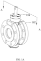
- FIG. 1A is a perspective view of a valve of the present application
- FIG. 1B is an exploded view of the valve shown in FIG. 1A
- the valve comprises a housing 102, a first valve body 104, a second valve body 106, a control assembly, and a cover 124.
- the first valve body 104 and the second valve body 106 are arranged in the housing 102.
- the control assembly controls the rotation of the first valve body 104 and the second valve body 106.
- the housing 102 defines a housing channel 142.
- the housing channel 142 is formed by extending in a front-back direction and has a substantially circular cross-section.
- a portion of the housing channel 142 is substantially spherical to accommodate the first valve body 104.
- the housing 102 also defines a control channel extending in an up-down direction.
- the control channel is in communication with the spherical housing channel 142.
- the cover 124 is arranged above the housing 102 and connected to the housing 102 to close the control channel.
- the first valve body 104 is substantially a truncated sphere that is truncated at the left and right ends.
- the first valve body 104 is arranged in the housing channel 142 and has a first valve body axis X.
- the first valve body axis X is arranged substantially perpendicular to the extension direction (i.e., the up-down direction) of the housing channel 142.
- the first valve body 104 is rotatable around the first valve body axis X.
- the first valve body 104 defines a valve body channel 146.
- the valve body channel 146 has a circular cross-section.
- the first valve body 104 has an open position and a closed position and is rotatable between the open position and the closed position.
- the extension direction of the valve body channel 146 is substantially consistent with the extension direction of the housing channel 142, and the valve body channel 146 is in fluid communication with the housing channel 142.
- the extension direction of the valve body channel 146 is substantially perpendicular to the extension direction of the housing channel 142, thereby disconnecting portions of the housing channel 142 flanking the valve body channel 146.
- the first valve body 104 is rotatable by 90° to be rotated between the open position and the closed position.
- the second valve body 106 is substantially plateshaped and has a substantially circular cross-section.
- the second valve body 106 is arranged in the valve body channel 146 of the first valve body 104 and has a second valve body axis Y.
- the second valve body axis Y is arranged along an up-down direction.
- the second valve body 106 is rotatable around the second valve body axis Y.
- the second valve body 106 has a first position and a second position and is rotatable between the first position and the second position. Specifically, when the second valve body 106 is in the first position, the plateshaped extension plane of the second valve body 106 is substantially arranged in a front-back direction, thereby connecting the valve body channel 146.
- the second valve body 106 When the second valve body 106 is in the second position, the second valve body 106 connects the valve body channel 146. It should also be noted that when the second valve body 106 is rotated between the first position and the second position, a flow rate of a fluid passing through the valve body channel 146 can be controlled. In the present application, the second valve body 106 is rotated by 90° to be rotated between the first position and the second position.
- first position and the second position of the second valve body 106 are relative to the housing 102 and the first valve body 104 being in the open position. That is, when the second valve body 106 is in the first position or the second position, the first valve body 104 is held in the open position.
- the second valve body 106 further has a third position.
- the third position of the second valve body 106 is relative to the housing 102. That is, when the second valve body 106 moves from the second position to the third position, the second valve body 106 is stationary relative to the first valve body 104 and moves relative to the housing 102. In the present application, when the second valve body 106 continues to be rotated by 90° from the second position, the second valve body 106 is in the third position.
- the movement of the first valve body 104 between the open position and the closed position, and the movement of the second valve body 106 among the first position, the second position, and the third position will be described below with reference to FIGS. 5A-5C .
- the control assembly comprises a shaft rod 108, a sleeve 122 and a reset device 126.
- the shaft rod 108 is connected to the second valve body 106, thereby being rotated together with the second valve body 106.
- the sleeve 122 is sleeved on the shaft rod 108 and connected to the first valve body 104, thereby being rotated together with the first valve body 104.
- the top of the first valve body 104 is provided with a first through-hole 151.
- the upper part of the second valve body 106 is provided with a first hole 152.
- the first hole 152 is formed by recessing downwardly from an upper part of the second valve body 106.
- a lower end of the shaft rod 108 is capable of being accommodated in the first hole 152 after passing through the first through-hole 151.
- the lower end of the shaft rod 108 and the first hole 152 are square-shaped, thereby enabling the shaft rod 108 and the second valve body 106 to be rotated together in a circumferential direction.
- a second through-hole 153 extending in an up-down direction is provided on the sleeve 122.
- the shaft rod 108 is accommodated within the second through-hole 153.
- An upper part of the first valve body 104 is provided with a second hole 154.
- the second hole is formed by recessing downwardly from the upper part of the first valve body 104.
- a lower end of the sleeve 122 is capable of being accommodated in the second hole 154.
- the lower end of the sleeve 122 and the second hole 154 are square-shaped, thereby enabling the sleeve 122 and the first valve body 104 to be rotated together in a circumferential direction.
- the reset device 126 is arranged on the sleeve 122, thereby rotating the first valve body 104 from the closed position to the open position.
- the reset device 126 is a torsion spring, and the torsion spring is arranged on the sleeve 122.
- One end of the torsion spring is arranged on the housing 102, and the other end of the torsion spring is arranged on the sleeve 122.
- the torsion spring is preloaded.
- the torsion spring applies a driving force to the first valve body 104 to rotate it from the closed position to the open position.
- the control assembly further comprises a first control structure arranged on the shaft rod 108 and the sleeve 122, and a second control structure provided on the cover 124 and the sleeve 122, wherein the first control structure is configured such that when the second valve body 106 is rotated from the second position to the third position, the second valve body 106 drives the first valve body 104 to be rotated from the open position to the closed position.
- the second control structure is configured to rotate the first valve body 104 between the open position and the closed position.
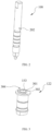
- FIG. 2 is a perspective view of the shaft rod 108 shown in FIG. 1B .
- FIG. 3 is a perspective view of the sleeve 122 shown in FIG. 1B .
- the first control structure comprises a shaft rod guide bar 202 provided on the shaft rod 108 and a sleeve guide groove 302 provided on the sleeve 122.
- the shaft rod guide bar 202 is formed by extending outwardly in a radial direction from a side of the shaft rod 108.
- An upper surface of the sleeve 122 is provided with an upwardly protruded stopper 301.
- the blocker 301 is continuously distributed in the circumferential direction over approximately 270°, thereby forming the sleeve guide groove 302 located between two ends of the stopper 301. That is, the sleeve guide groove 302 is disposed along a circumferential direction of the sleeve 122 and distributed at an angle of substantially 90° (i.e., the angle formed by two ends of the sleeve guide groove 302 is 90°).
- the shaft rod guide bar 202 is accommodated within the sleeve guide groove 302 and rotated in the sleeve guide groove 302, the shaft rod 108 is capable of being rotated relative to the sleeve 122.
- the shaft rod guide bar 202 When the shaft rod guide bar 202 is located at an end of the sleeve guide groove 302, the shaft rod guide bar 202 is capable of applying a force to the sleeve 122 in a circumferential direction, thereby driving the sleeve 122 to be rotated.
- FIG. 4 is a perspective view of the cover 124 shown in FIG. 1B .
- the second control structure comprises a sleeve guide bar 304 arranged on the sleeve 122 and a cover guide groove 402 arranged on the cover 124.
- the sleeve guide bar 304 is formed by extending upwardly (i.e., in an axial direction) from the upper surface of the sleeve 122.
- the cover guide groove 402 is arranged on a lower surface of the cover 124 and is formed by recessing upwardly from the lower surface of the cover 124.
- the cover guide groove 402 is distributed at an angle of substantially 90° (i.e., the angle formed by two ends of the cover guide groove 402 is 90°). Since the cover 124 is connected to the housing 102, the cover guide groove 402 in the cover 124 is capable of maintaining a rotational angle of 90° accommodated in the sleeve guide bar 304.
- FIG. 5A is a schematic diagram of the first control structure and the second control structure when the first valve body 104 is in the open position and the second valve body 106 is in the first position.
- FIG. 5B is a schematic diagram of the first control structure and the second control structure when the first valve body 104 is in the closed position and the second valve body 106 is in the second position.
- FIG. 5C is a schematic diagram of the first control structure and the second control structure when the first valve body 104 is in the closed position and the second valve body 106 is in the third position. As shown in FIG.
- the shaft rod guide bar 202 is located at a first end (i.e., the right end) of the sleeve guide groove 302 and sleeve guide bar 304 is located at a first end (i.e., the left end) of the cover guide groove 402.
- the shaft rod 108 can be controlled to be rotated, thereby rotating the second valve body 106 to adjust a flow area of the valve body channel 146.
- the second valve body 106 is rotated from the first position to the second position.
- the flow area of the valve body channel 146 gradually decreases until the second valve body 106 disconnects the valve body channel 146, and the valve is closed.
- the first valve body 104 is in the open position and the second valve body 106 is in the second position.
- the shaft rod guide bar 202 is located at a second end (i.e., the left end) of the sleeve guide groove 302 and the sleeve guide bar 304 is located at the first end (i.e., the left end) of the cover guide groove 402.
- the shaft rod guide bar 202 of the shaft rod 108 abuts against the edge of the sleeve guide groove 302, thereby applying a force to the sleeve 122 and driving the sleeve 122 to be rotated in the counter-clockwise direction.
- the first valve body 104 is in the closed position and the second valve body 106 is in the third position.
- the shaft rod guide bar 202 is located at the second end of the sleeve guide groove 302, and the sleeve guide bar 304 is located at a second end (i.e., the right end) of the cover guide groove 402.
- the second valve body 106 disconnects the valve body channel 146, and the first valve body 104 disconnects the housing channel 142, the valve remaining closed. It should be noted that during the rotation, the torsion spring is preloaded.
- the shaft rod guide bar 202 is located at the second end of the sleeve guide groove 302 and the sleeve guide bar 304 is located at the second end (i.e., the right end) of the cover guide groove 402.
- the shaft rod 108 can be controlled to be rotated in a clockwise direction, thereby rotating the second valve body 106.
- the preloaded torsion spring is capable of applying a force to the sleeve 122 so that the sleeve 122 and the first valve body 104 connected to the sleeve 122 are also rotated in the clockwise direction.
- both the first valve body 104 and the second valve body 106 are rotated by 90° in the clockwise direction, with the first valve body 104 in the open position and the second valve body 106 in the second position.
- the shaft rod 108 continues to be rotated by 90° in the clockwise direction so that the shaft rod guide bar 202 continues to be rotated by 90° in the clockwise direction within the sleeve guide groove 302 so as to be rotated from the second position to the first position.
- the valve is opened.
- a butterfly valve is used for regulating the flow rate
- a ball valve is used for shutting off flow of fluid.
- existing valves are not capable of achieving functions of both the butterfly valves and the ball valves simultaneously. Even though some of the valves have integrated the functions of the butterfly valve and the ball valve, those valves require two controllers to control the butterfly valve and the ball valve, respectively, which complicates the control process.
- the rotation of the first valve body 104 and the second valve body 106 is controlled by the control assembly. More specifically, an external control device (for example, an electric motor) controls the opening and closing of the valve simply by means of controlling a shaft rod 108, thereby simplifying the control logic of the valve.
- an external control device for example, an electric motor
Landscapes
- Engineering & Computer Science (AREA)
- General Engineering & Computer Science (AREA)
- Mechanical Engineering (AREA)
- Lift Valve (AREA)
- Electrically Driven Valve-Operating Means (AREA)
- Multiple-Way Valves (AREA)
- Taps Or Cocks (AREA)
Abstract
Description
- The present application relates to the field of valves.
- In the state of art, a butterfly valve is used for regulating the flow rate, and a ball valve is used for shutting off flow of fluid. However, existing valves are not capable of achieving functions of both the butterfly valves and the ball valves simultaneously.
- Exemplary embodiments of the present application can address at least some of the problems described above. The present application provides a valve, comprising a housing, a first valve body, a second valve body and a control assembly. The housing defines a housing channel. The first valve body is arranged in the housing channel in a rotatable manner, defines a valve body channel, and can connect or disconnect the housing channel. The second valve body is arranged in the valve body channel in a rotatable manner, so as to connect or disconnect the valve body channel. The control assembly is configured to control the rotation of the first valve body and the second valve body.
- According to the valve described above, the second valve body has a first position, a second position and a third position and is rotatable among the first position, the second position and the third position, and the first valve body has an open position and a closed position and is rotatable between the open position and the closed position, wherein the control assembly, the first valve body and the second valve body are configured such that when the second valve body is rotated between the first position and the second position, the first valve body is in the open position; when the second valve body is rotated from the second position to the third position, the second valve body drives the first valve body to be rotated from the open position to the closed position.
- According to the valve described above, the valve further comprises a reset device. The reset device is configured such that when the second valve body is rotated from the third position to the second position, the reset device rotates the first valve body from the closed position to the open position.
- According to the valve described above, the control assembly comprises a shaft rod, a sleeve and a cover. The shaft rod is connected to the second valve body and rotated together with the second valve body. The sleeve is sleeved on the shaft rod and rotated together with the first valve body. A cover, the cover being arranged above the sleeve and connected to the housing. The shaft rod and the sleeve are provided with a first control structure thereon, the first control structure being configured such that when the second valve body is rotated from the second position to the third position, the second valve body drives the first valve body to be rotated from the open position to the closed position. The cover and the sleeve are provided with a second control structure thereon, the second control structure being configured to rotate the first valve body between the open position and the closed position.
- According to the valve described above, the reset device is a torsion spring, one end of the torsion spring being arranged on the housing, and the other end of the torsion spring being arranged on the sleeve.
- According to the valve described above, the first control structure comprises a shaft rod guide bar being arranged on a side of the shaft rod and extending outwardly in a radial direction, and a sleeve guide groove being arranged on the sleeve and disposed circumferentially. The sleeve guide groove and the shaft rod guide bar are configured such that when the shaft rod guide bar is accommodated in the sleeve guide groove and rotated within the sleeve guide groove, the shaft rod is movable relative to the sleeve; when the shaft rod guide bar is located at an end of the sleeve guide groove, the shaft rod guide bar is capable of applying a force to the sleeve to drive the sleeve to be rotated.
- According to the valve described above, angle formed by two ends of the sleeve guide groove is 90°.
- According to the valve described above, the second control structure comprises a sleeve guide bar being arranged at an upper part of the sleeve and extending in an axial direction, and a cover guide groove being arranged on the cover and disposed circumferentially.
- According to the valve described above, the angle formed by two ends of the cover guide groove is 90°.
- According to the valve described above, when the second valve body is located and rotated between the first position and the second position, the second valve body is capable of regulating a flow rate of a fluid flowing through the valve.
- The valve of the present application is controlled to rotate by means of the control assembly. More specifically, an external control device (for example, an electric motor) controls the opening and closing of the valve simply by means of controlling a shaft rod, thereby simplifying the control logic of the valve.
- The features and advantages of the present application may be better understood by reading the following detailed description with reference to the accompanying drawings, throughout which the same components will be denoted by the same reference numerals, and in which:
-
FIG. 1A is a perspective view of a valve of the present application; -
FIG. 1B is an exploded view of the valve shown inFIG. 1A ; -
FIG. 2 is a perspective view of the shaft rod shown inFIG. 1B ; -
FIG. 3 is a perspective view of the sleeve shown inFIG. 1B ; -
FIG. 4 is a perspective view of the cover shown inFIG. 1B ; -
FIG. 5A is a schematic diagram of a first control structure and a second control structure when a first valve body is in an open position and a second valve body is in a first position; -
FIG. 5B is a schematic diagram of the first control structure and the second control structure when the first valve body is in a closed position and the second valve body is in a second position; and -
FIG. 5C is a schematic diagram of the first control structure and the second control structure when the first valve body is in the closed position and the second valve body is in a third position. - Various specific implementations of the present invention will be described below with reference to the accompanying drawings, which constitute a part of this specification. It should be understood that although terms, such as "front", "back", "up", "down", "left", "right" etc., that represent directions are used in the present invention to directionally or orientationally describe various example structural parts and elements of the present invention, these terms are used here for ease of illustration only and determined based on example orientations shown in the accompanying drawings. Since the embodiments disclosed in the present invention may be disposed in different directions, these terms that represent directions are for illustration only and should not be considered as limitation. In the accompanying drawings below, the same reference numerals will be used for the same parts.
-
FIG. 1A is a perspective view of a valve of the present application, andFIG. 1B is an exploded view of the valve shown inFIG. 1A . As shown inFIGS. 1A-1B , the valve comprises ahousing 102, afirst valve body 104, asecond valve body 106, a control assembly, and acover 124. Thefirst valve body 104 and thesecond valve body 106 are arranged in thehousing 102. The control assembly controls the rotation of thefirst valve body 104 and thesecond valve body 106. Specifically, thehousing 102 defines a housing channel 142.Thehousing channel 142 is formed by extending in a front-back direction and has a substantially circular cross-section. A portion of thehousing channel 142 is substantially spherical to accommodate thefirst valve body 104. Thehousing 102 also defines a control channel extending in an up-down direction. The control channel is in communication with thespherical housing channel 142. Thecover 124 is arranged above thehousing 102 and connected to thehousing 102 to close the control channel. - As shown in
FIGS. 1A-1B , thefirst valve body 104 is substantially a truncated sphere that is truncated at the left and right ends. Thefirst valve body 104 is arranged in thehousing channel 142 and has a first valve body axis X. The first valve body axis X is arranged substantially perpendicular to the extension direction (i.e., the up-down direction) of thehousing channel 142. Thefirst valve body 104 is rotatable around the first valve body axis X. Thefirst valve body 104 defines avalve body channel 146. Thevalve body channel 146 has a circular cross-section. Thefirst valve body 104 has an open position and a closed position and is rotatable between the open position and the closed position. Specifically, when thefirst valve body 104 is in the open position, the extension direction of thevalve body channel 146 is substantially consistent with the extension direction of thehousing channel 142, and thevalve body channel 146 is in fluid communication with the housing channel 142.When thefirst valve body 104 is in the closed position, the extension direction of thevalve body channel 146 is substantially perpendicular to the extension direction of thehousing channel 142, thereby disconnecting portions of thehousing channel 142 flanking thevalve body channel 146. In the present application, thefirst valve body 104 is rotatable by 90° to be rotated between the open position and the closed position. - As shown in
FIGS. 1A-1B , thesecond valve body 106 is substantially plateshaped and has a substantially circular cross-section. Thesecond valve body 106 is arranged in thevalve body channel 146 of thefirst valve body 104 and has a second valve body axis Y. The second valve body axis Y is arranged along an up-down direction. Thesecond valve body 106 is rotatable around the second valve body axis Y. Thesecond valve body 106 has a first position and a second position and is rotatable between the first position and the second position. Specifically, when thesecond valve body 106 is in the first position, the plateshaped extension plane of thesecond valve body 106 is substantially arranged in a front-back direction, thereby connecting thevalve body channel 146. When thesecond valve body 106 is in the second position, thesecond valve body 106 connects thevalve body channel 146. It should also be noted that when thesecond valve body 106 is rotated between the first position and the second position, a flow rate of a fluid passing through thevalve body channel 146 can be controlled. In the present application, thesecond valve body 106 is rotated by 90° to be rotated between the first position and the second position. - It should be noted that the first position and the second position of the
second valve body 106 are relative to thehousing 102 and thefirst valve body 104 being in the open position. That is, when thesecond valve body 106 is in the first position or the second position, thefirst valve body 104 is held in the open position. - In addition, the
second valve body 106 further has a third position. The third position of thesecond valve body 106 is relative to thehousing 102. That is, when thesecond valve body 106 moves from the second position to the third position, thesecond valve body 106 is stationary relative to thefirst valve body 104 and moves relative to thehousing 102. In the present application, when thesecond valve body 106 continues to be rotated by 90° from the second position, thesecond valve body 106 is in the third position. - The movement of the
first valve body 104 between the open position and the closed position, and the movement of thesecond valve body 106 among the first position, the second position, and the third position will be described below with reference toFIGS. 5A-5C . - As shown in
FIGS. 1A-1B , the control assembly comprises ashaft rod 108, asleeve 122 and areset device 126. Theshaft rod 108 is connected to thesecond valve body 106, thereby being rotated together with thesecond valve body 106. Thesleeve 122 is sleeved on theshaft rod 108 and connected to thefirst valve body 104, thereby being rotated together with thefirst valve body 104. Specifically, the top of thefirst valve body 104 is provided with a first through-hole 151. The upper part of thesecond valve body 106 is provided with afirst hole 152. Thefirst hole 152 is formed by recessing downwardly from an upper part of thesecond valve body 106. A lower end of theshaft rod 108 is capable of being accommodated in thefirst hole 152 after passing through the first through-hole 151. As an example, the lower end of theshaft rod 108 and thefirst hole 152 are square-shaped, thereby enabling theshaft rod 108 and thesecond valve body 106 to be rotated together in a circumferential direction. A second through-hole 153 extending in an up-down direction is provided on thesleeve 122. Theshaft rod 108 is accommodated within the second through-hole 153. An upper part of thefirst valve body 104 is provided with asecond hole 154. The second hole is formed by recessing downwardly from the upper part of thefirst valve body 104. A lower end of thesleeve 122 is capable of being accommodated in thesecond hole 154. As an example, the lower end of thesleeve 122 and thesecond hole 154 are square-shaped, thereby enabling thesleeve 122 and thefirst valve body 104 to be rotated together in a circumferential direction. Thereset device 126 is arranged on thesleeve 122, thereby rotating thefirst valve body 104 from the closed position to the open position. In the present application, thereset device 126 is a torsion spring, and the torsion spring is arranged on thesleeve 122. One end of the torsion spring is arranged on thehousing 102, and the other end of the torsion spring is arranged on thesleeve 122. When thefirst valve body 104 is rotated from the open position to the closed position, the torsion spring is preloaded. When thefirst valve body 104 is in the closed position, the torsion spring applies a driving force to thefirst valve body 104 to rotate it from the closed position to the open position. - The control assembly further comprises a first control structure arranged on the
shaft rod 108 and thesleeve 122, and a second control structure provided on thecover 124 and thesleeve 122, wherein the first control structure is configured such that when thesecond valve body 106 is rotated from the second position to the third position, thesecond valve body 106 drives thefirst valve body 104 to be rotated from the open position to the closed position. The second control structure is configured to rotate thefirst valve body 104 between the open position and the closed position. -
FIG. 2 is a perspective view of theshaft rod 108 shown inFIG. 1B .FIG. 3 is a perspective view of thesleeve 122 shown inFIG. 1B . As shown inFIGS. 2-3 , the first control structure comprises a shaftrod guide bar 202 provided on theshaft rod 108 and asleeve guide groove 302 provided on thesleeve 122. Specifically, the shaftrod guide bar 202 is formed by extending outwardly in a radial direction from a side of theshaft rod 108. An upper surface of thesleeve 122 is provided with an upwardlyprotruded stopper 301. Theblocker 301 is continuously distributed in the circumferential direction over approximately 270°, thereby forming thesleeve guide groove 302 located between two ends of thestopper 301. That is, thesleeve guide groove 302 is disposed along a circumferential direction of thesleeve 122 and distributed at an angle of substantially 90° (i.e., the angle formed by two ends of thesleeve guide groove 302 is 90°). When the shaftrod guide bar 202 is accommodated within thesleeve guide groove 302 and rotated in thesleeve guide groove 302, theshaft rod 108 is capable of being rotated relative to thesleeve 122. When the shaftrod guide bar 202 is located at an end of thesleeve guide groove 302, the shaftrod guide bar 202 is capable of applying a force to thesleeve 122 in a circumferential direction, thereby driving thesleeve 122 to be rotated. -
FIG. 4 is a perspective view of thecover 124 shown inFIG. 1B . As shown inFIGS. 3-4 , the second control structure comprises asleeve guide bar 304 arranged on thesleeve 122 and acover guide groove 402 arranged on thecover 124. Specifically, thesleeve guide bar 304 is formed by extending upwardly (i.e., in an axial direction) from the upper surface of thesleeve 122. Thecover guide groove 402 is arranged on a lower surface of thecover 124 and is formed by recessing upwardly from the lower surface of thecover 124. Thecover guide groove 402 is distributed at an angle of substantially 90° (i.e., the angle formed by two ends of thecover guide groove 402 is 90°). Since thecover 124 is connected to thehousing 102, thecover guide groove 402 in thecover 124 is capable of maintaining a rotational angle of 90° accommodated in thesleeve guide bar 304. -
FIG. 5A is a schematic diagram of the first control structure and the second control structure when thefirst valve body 104 is in the open position and thesecond valve body 106 is in the first position.FIG. 5B is a schematic diagram of the first control structure and the second control structure when thefirst valve body 104 is in the closed position and thesecond valve body 106 is in the second position.FIG. 5C is a schematic diagram of the first control structure and the second control structure when thefirst valve body 104 is in the closed position and thesecond valve body 106 is in the third position. As shown inFIG. 5A , when thefirst valve body 104 is in the open position and thesecond valve body 106 is in the first position, the shaftrod guide bar 202 is located at a first end (i.e., the right end) of thesleeve guide groove 302 andsleeve guide bar 304 is located at a first end (i.e., the left end) of thecover guide groove 402. When it is necessary to control the flow rate of the fluid passing through the valve, theshaft rod 108 can be controlled to be rotated, thereby rotating thesecond valve body 106 to adjust a flow area of thevalve body channel 146. As theshaft rod 108 is rotated in the counter-clockwise direction by 90°, thesecond valve body 106 is rotated from the first position to the second position. During the rotation, the flow area of thevalve body channel 146 gradually decreases until thesecond valve body 106 disconnects thevalve body channel 146, and the valve is closed. At this point, thefirst valve body 104 is in the open position and thesecond valve body 106 is in the second position. More specifically, the shaftrod guide bar 202 is located at a second end (i.e., the left end) of thesleeve guide groove 302 and thesleeve guide bar 304 is located at the first end (i.e., the left end) of thecover guide groove 402. It should be noted that during the rotation, since the shaftrod guide bar 202 is rotated relative to thesleeve 122 within thesleeve guide groove 302 during the rotation of theshaft rod 108, the position of thefirst valve body 104 remains unchanged at this point. - As the
shaft rod 108 continues to be rotated in the counter-clockwise direction, the shaftrod guide bar 202 of theshaft rod 108 abuts against the edge of thesleeve guide groove 302, thereby applying a force to thesleeve 122 and driving thesleeve 122 to be rotated in the counter-clockwise direction. When thesleeve 122 has been rotated in the counter-clockwise direction by 90°, thefirst valve body 104 is in the closed position and thesecond valve body 106 is in the third position. More specifically, the shaftrod guide bar 202 is located at the second end of thesleeve guide groove 302, and thesleeve guide bar 304 is located at a second end (i.e., the right end) of thecover guide groove 402. At this point, thesecond valve body 106 disconnects thevalve body channel 146, and thefirst valve body 104 disconnects thehousing channel 142, the valve remaining closed. It should be noted that during the rotation, the torsion spring is preloaded. - The opening process of the valve will be described below with reference to
FIGS. 5C-5A . As shown inFIG. 5C , when thefirst valve body 104 is in the closed position and thesecond valve body 106 is in the third position, the shaftrod guide bar 202 is located at the second end of thesleeve guide groove 302 and thesleeve guide bar 304 is located at the second end (i.e., the right end) of thecover guide groove 402. When it is necessary to open the valve, theshaft rod 108 can be controlled to be rotated in a clockwise direction, thereby rotating thesecond valve body 106. Although theshaft rod 108 is controlled to be rotated in the clockwise direction, the preloaded torsion spring is capable of applying a force to thesleeve 122 so that thesleeve 122 and thefirst valve body 104 connected to thesleeve 122 are also rotated in the clockwise direction. As a result, both thefirst valve body 104 and thesecond valve body 106 are rotated by 90° in the clockwise direction, with thefirst valve body 104 in the open position and thesecond valve body 106 in the second position. Subsequently, theshaft rod 108 continues to be rotated by 90° in the clockwise direction so that the shaftrod guide bar 202 continues to be rotated by 90° in the clockwise direction within thesleeve guide groove 302 so as to be rotated from the second position to the first position. As a result, the valve is opened. - Among the existing valves, a butterfly valve is used for regulating the flow rate, and a ball valve is used for shutting off flow of fluid. However, existing valves are not capable of achieving functions of both the butterfly valves and the ball valves simultaneously. Even though some of the valves have integrated the functions of the butterfly valve and the ball valve, those valves require two controllers to control the butterfly valve and the ball valve, respectively, which complicates the control process.
- In the valve of the present application, the rotation of the
first valve body 104 and thesecond valve body 106 is controlled by the control assembly. More specifically, an external control device (for example, an electric motor) controls the opening and closing of the valve simply by means of controlling ashaft rod 108, thereby simplifying the control logic of the valve. - Although the present disclosure has been described in conjunction with the examples of embodiments outlined above, various alternatives, modifications, variations, improvements and/or substantial equivalents, whether currently known or foreseeable now or in the near future, may be obvious to those of at least ordinary skill in the art. In addition, the technical effects and/or technical problems described in the present specification are exemplary, and not limiting; Therefore, the disclosure in the present specification may be used to address other technical problems and have other technical effects and/or can address other technical problems. Accordingly, the examples of embodiments of the present disclosure, as set forth above, are intended to be illustrative, and not limiting. Various changes can be practiced without departing from the spirit or scope of the present disclosure. Accordingly, the present disclosure is intended to cover all known or earlier developed alternatives, modifications, variations, improvements and/or substantial equivalents.
Claims (10)
- A valve, comprising:a housing (102), the housing (102) defining a housing channel (142);a first valve body (104), the first valve body (104) being arranged in the housing channel (142) in a rotatable manner and defining a valve body channel (146), and the first valve body (104) being capable of connecting or disconnecting the housing channel (142);a second valve body (106), the second valve body (106) being arranged in the valve body channel (146) in a rotatable manner, so as to connect or disconnect the valve body channel (146); anda control assembly, the control assembly being configured to control the rotation of the first valve body (104) and the second valve body (106).
- The valve according to claim 1, whereinthe second valve body (106) has a first position, a second position and a third position and is rotatable among the first position, the second position and the third position, and the first valve body (104) has an open position and a closed position and is rotatable between the open position and the closed position;wherein the control assembly, the first valve body (104) and the second valve body (106) are configured such that when the second valve body (106) is rotated between the first position and the second position, the first valve body (104) is in the open position; and when the second valve body (106) is rotated from the second position to the third position, the second valve body (106) drives the first valve body (104) to be rotated from the open position to the closed position.
- The valve according to claim 2, wherein the valve further comprises:a reset device (126);and the reset device (126) is configured such that when the second valve body (106) is rotated from the third position to the second position, the reset device (126) rotates the first valve body (104) from the closed position to the open position.
- The valve according to claim 3, wherein the control assembly comprises:a shaft rod (108), the shaft rod (108) being connected to the second valve body (106) and rotated together with the second valve body (106);a sleeve (122), the sleeve (122) being sleeved on the shaft rod (108) and rotated together with the first valve body (104); anda cover (124), the cover (124) being arranged above the sleeve (122) and connected to the housing (102);wherein the shaft rod (108) and the sleeve (122) are provided with a first control structure thereon, the first control structure being configured such that when the second valve body (106) is rotated from the second position to the third position, the second valve body (106) drives the first valve body (104) to be rotated from the open position to the closed position;wherein the cover (124) and the sleeve (122) are provided with a second control structure thereon, the second control structure being configured to rotate the first valve body (104) between the open position and the closed position.
- The valve according to claim 4, wherein:
the reset device (126) is a torsion spring, one end of the torsion spring being arranged on the housing (102), and the other end of the torsion spring being arranged on the sleeve (122). - The valve according to claim 4, wherein:the first control structure comprises a shaft rod guide bar (202) being arranged on a side of the shaft rod (108) and extending outwardly in a radial direction, and a sleeve guide groove (302) being arranged on the sleeve (122) and disposed circumferentially;the sleeve guide groove (302) and the shaft rod guide bar (202) are configured such that when the shaft rod guide bar (202) is accommodated in the sleeve guide groove (302) and rotated within the sleeve guide groove (302), the shaft rod (108) is movable relative to the sleeve (122); and when the shaft rod guide bar (202) is located at an end of the sleeve guide groove (302), the shaft rod guide bar (202) is capable of applying a force to the sleeve (122) to drive the sleeve (122) to be rotated.
- The valve according to claim 6, wherein:
the angle formed by two ends of the sleeve guide groove (302) is 90°. - The valve according to claim 4, wherein:
the second control structure comprises a sleeve guide bar (304) being arranged at an upper part of the sleeve (122) and extending in an axial direction, and a cover guide groove (402) being arranged on the cover (124) and disposed circumferentially. - The valve according to claim 8, wherein:
the angle formed by two ends of the cover guide groove (402) is 90°. - The valve according to claim 2, wherein:
when the second valve body (106) is located and rotated between the first position and the second position, the second valve body (106) is capable of regulating a flow rate of a fluid flowing through the valve.
Applications Claiming Priority (2)
| Application Number | Priority Date | Filing Date | Title |
|---|---|---|---|
| CN202210849492.6A CN115183018B (en) | 2022-07-19 | 2022-07-19 | valve |
| PCT/CN2023/107710 WO2024017194A1 (en) | 2022-07-19 | 2023-07-17 | Valve |
Publications (1)
| Publication Number | Publication Date |
|---|---|
| EP4567311A1 true EP4567311A1 (en) | 2025-06-11 |
Family
ID=83518758
Family Applications (1)
| Application Number | Title | Priority Date | Filing Date |
|---|---|---|---|
| EP23842257.0A Pending EP4567311A1 (en) | 2022-07-19 | 2023-07-17 | Valve |
Country Status (6)
| Country | Link |
|---|---|
| US (1) | US20250389333A1 (en) |
| EP (1) | EP4567311A1 (en) |
| KR (1) | KR20250084104A (en) |
| CN (1) | CN115183018B (en) |
| TW (1) | TW202409456A (en) |
| WO (1) | WO2024017194A1 (en) |
Families Citing this family (1)
| Publication number | Priority date | Publication date | Assignee | Title |
|---|---|---|---|---|
| CN115183018B (en) * | 2022-07-19 | 2025-12-23 | 约克广州空调冷冻设备有限公司 | valve |
Family Cites Families (13)
| Publication number | Priority date | Publication date | Assignee | Title |
|---|---|---|---|---|
| FR1511656A (en) * | 1966-12-23 | 1968-02-02 | Self-regulating, adjustable flow ball valve | |
| CN1071742A (en) * | 1991-10-19 | 1993-05-05 | 上海市精工阀门厂 | Butterfly ball valve |
| DE102008008801A1 (en) * | 2008-02-12 | 2009-10-15 | Franz Schuck Gmbh | ball valve |
| JP2012211617A (en) * | 2011-03-30 | 2012-11-01 | Keihin Corp | Valve device |
| JP2012247012A (en) * | 2011-05-27 | 2012-12-13 | Keihin Corp | Valve device |
| CN102788166A (en) * | 2012-08-22 | 2012-11-21 | 董振友 | Cut-off adjusting and metering valve |
| CN103498948B (en) * | 2013-09-25 | 2016-08-24 | 浙江威腾阀门有限公司 | A kind of multipurpose ball valve |
| KR20170084932A (en) * | 2016-01-13 | 2017-07-21 | 동아대학교 산학협력단 | Hybrid valve for micro flow control |
| CN107917203A (en) * | 2017-12-06 | 2018-04-17 | 凯瑞特阀业有限公司 | Butterfly valve |
| CN210661506U (en) * | 2019-06-03 | 2020-06-02 | 苏州博雷特流体控制有限公司 | Hard sealing ball valve with adjustable flow |
| CN210770607U (en) * | 2019-10-30 | 2020-06-16 | 苏州赛孚特阀门有限公司 | Wear-resistant valve |
| CN114233877B (en) * | 2021-12-21 | 2022-05-20 | 宁波一机阀门制造有限公司 | A suspended self-pressure metal-sealed butterfly valve |
| CN115183018B (en) * | 2022-07-19 | 2025-12-23 | 约克广州空调冷冻设备有限公司 | valve |
-
2022
- 2022-07-19 CN CN202210849492.6A patent/CN115183018B/en active Active
-
2023
- 2023-07-17 WO PCT/CN2023/107710 patent/WO2024017194A1/en not_active Ceased
- 2023-07-17 EP EP23842257.0A patent/EP4567311A1/en active Pending
- 2023-07-17 KR KR1020257005495A patent/KR20250084104A/en active Pending
- 2023-07-17 US US18/996,698 patent/US20250389333A1/en active Pending
- 2023-07-18 TW TW112126774A patent/TW202409456A/en unknown
Also Published As
| Publication number | Publication date |
|---|---|
| CN115183018B (en) | 2025-12-23 |
| TW202409456A (en) | 2024-03-01 |
| KR20250084104A (en) | 2025-06-10 |
| WO2024017194A1 (en) | 2024-01-25 |
| US20250389333A1 (en) | 2025-12-25 |
| CN115183018A (en) | 2022-10-14 |
Similar Documents
| Publication | Publication Date | Title |
|---|---|---|
| US20250389333A1 (en) | Valve | |
| US6776394B2 (en) | Pendulum valve assembly | |
| JP6214487B2 (en) | Motorized valve | |
| US20190126728A1 (en) | Air vent for vehicle | |
| US7740228B2 (en) | Valve assembly including a torsion spring coupling a valve shaft and actuator shaft | |
| JP6270650B2 (en) | Motorized valve | |
| CN101539213A (en) | Flow rate regulating valve | |
| JP2017201199A (en) | Flow adjustment valve | |
| KR20170084932A (en) | Hybrid valve for micro flow control | |
| JP2017201198A (en) | Flow adjustment valve | |
| CN111765251B (en) | Electronic expansion valve | |
| EP3665023B1 (en) | Air ventilator for an automobile | |
| JP4255532B2 (en) | Motion transmission device using pivot lever and valve incorporating the device | |
| US20180245710A1 (en) | Valve actuator | |
| US20180231129A1 (en) | Valve assembly with rotatable element | |
| JP5329131B2 (en) | Long stroke regulator valve with shut-off function | |
| CN120552578A (en) | An easily adjustable automobile air-conditioning outlet assembly | |
| KR20150021086A (en) | Ball-and-socket joint as engagement point for a driving element of a locking system | |
| JP5873739B2 (en) | Toggle valve | |
| JP2002516935A (en) | Water faucet with adjustable delivery spout and operating lever | |
| CN110978960A (en) | Wind direction adjusting device | |
| CN209604599U (en) | A kind of threeway plug valve | |
| JP3620816B2 (en) | Motor with friction mechanism and fluid flow control device using this motor | |
| KR102491812B1 (en) | Pressure regulator with fine control | |
| KR101792713B1 (en) | Check valve with ball type swing members |
Legal Events
| Date | Code | Title | Description |
|---|---|---|---|
| STAA | Information on the status of an ep patent application or granted ep patent |
Free format text: STATUS: THE INTERNATIONAL PUBLICATION HAS BEEN MADE |
|
| PUAI | Public reference made under article 153(3) epc to a published international application that has entered the european phase |
Free format text: ORIGINAL CODE: 0009012 |
|
| STAA | Information on the status of an ep patent application or granted ep patent |
Free format text: STATUS: REQUEST FOR EXAMINATION WAS MADE |
|
| 17P | Request for examination filed |
Effective date: 20250219 |
|
| AK | Designated contracting states |
Kind code of ref document: A1 Designated state(s): AL AT BE BG CH CY CZ DE DK EE ES FI FR GB GR HR HU IE IS IT LI LT LU LV MC ME MK MT NL NO PL PT RO RS SE SI SK SM TR |
|
| RAP1 | Party data changed (applicant data changed or rights of an application transferred) |
Owner name: TYCO FIRE & SECURITY GMBH Owner name: YORK GUANGZHOU AIR CONDITIONING ANDREFRIGERATION CO., LTD. |
|
| DAV | Request for validation of the european patent (deleted) | ||
| DAX | Request for extension of the european patent (deleted) |