EP4567302A1 - Epicyclic system with bevel attachment for dual-power applications - Google Patents
Epicyclic system with bevel attachment for dual-power applications Download PDFInfo
- Publication number
- EP4567302A1 EP4567302A1 EP24218414.1A EP24218414A EP4567302A1 EP 4567302 A1 EP4567302 A1 EP 4567302A1 EP 24218414 A EP24218414 A EP 24218414A EP 4567302 A1 EP4567302 A1 EP 4567302A1
- Authority
- EP
- European Patent Office
- Prior art keywords
- gear
- arrangement
- reduction gearbox
- accessory component
- epicyclic
- Prior art date
- Legal status (The legal status is an assumption and is not a legal conclusion. Google has not performed a legal analysis and makes no representation as to the accuracy of the status listed.)
- Pending
Links
Images


Classifications
-
- F—MECHANICAL ENGINEERING; LIGHTING; HEATING; WEAPONS; BLASTING
- F16—ENGINEERING ELEMENTS AND UNITS; GENERAL MEASURES FOR PRODUCING AND MAINTAINING EFFECTIVE FUNCTIONING OF MACHINES OR INSTALLATIONS; THERMAL INSULATION IN GENERAL
- F16H—GEARING
- F16H37/00—Combinations of mechanical gearings, not provided for in groups F16H1/00 - F16H35/00
- F16H37/02—Combinations of mechanical gearings, not provided for in groups F16H1/00 - F16H35/00 comprising essentially only toothed or friction gearings
- F16H37/06—Combinations of mechanical gearings, not provided for in groups F16H1/00 - F16H35/00 comprising essentially only toothed or friction gearings with a plurality of driving or driven shafts; with arrangements for dividing torque between two or more intermediate shafts
- F16H37/065—Combinations of mechanical gearings, not provided for in groups F16H1/00 - F16H35/00 comprising essentially only toothed or friction gearings with a plurality of driving or driven shafts; with arrangements for dividing torque between two or more intermediate shafts with a plurality of driving or driven shafts
-
- B—PERFORMING OPERATIONS; TRANSPORTING
- B64—AIRCRAFT; AVIATION; COSMONAUTICS
- B64D—EQUIPMENT FOR FITTING IN OR TO AIRCRAFT; FLIGHT SUITS; PARACHUTES; ARRANGEMENT OR MOUNTING OF POWER PLANTS OR PROPULSION TRANSMISSIONS IN AIRCRAFT
- B64D35/00—Transmitting power from power plants to propellers or rotors; Arrangements of transmissions
- B64D35/02—Transmitting power from power plants to propellers or rotors; Arrangements of transmissions specially adapted for specific power plants
-
- F—MECHANICAL ENGINEERING; LIGHTING; HEATING; WEAPONS; BLASTING
- F01—MACHINES OR ENGINES IN GENERAL; ENGINE PLANTS IN GENERAL; STEAM ENGINES
- F01D—NON-POSITIVE DISPLACEMENT MACHINES OR ENGINES, e.g. STEAM TURBINES
- F01D15/00—Adaptations of machines or engines for special use; Combinations of engines with devices driven thereby
- F01D15/12—Combinations with mechanical gearing
-
- F—MECHANICAL ENGINEERING; LIGHTING; HEATING; WEAPONS; BLASTING
- F02—COMBUSTION ENGINES; HOT-GAS OR COMBUSTION-PRODUCT ENGINE PLANTS
- F02C—GAS-TURBINE PLANTS; AIR INTAKES FOR JET-PROPULSION PLANTS; CONTROLLING FUEL SUPPLY IN AIR-BREATHING JET-PROPULSION PLANTS
- F02C7/00—Features, components parts, details or accessories, not provided for in, or of interest apart form groups F02C1/00 - F02C6/00; Air intakes for jet-propulsion plants
- F02C7/32—Arrangement, mounting, or driving, of auxiliaries
-
- F—MECHANICAL ENGINEERING; LIGHTING; HEATING; WEAPONS; BLASTING
- F02—COMBUSTION ENGINES; HOT-GAS OR COMBUSTION-PRODUCT ENGINE PLANTS
- F02C—GAS-TURBINE PLANTS; AIR INTAKES FOR JET-PROPULSION PLANTS; CONTROLLING FUEL SUPPLY IN AIR-BREATHING JET-PROPULSION PLANTS
- F02C7/00—Features, components parts, details or accessories, not provided for in, or of interest apart form groups F02C1/00 - F02C6/00; Air intakes for jet-propulsion plants
- F02C7/36—Power transmission arrangements between the different shafts of the gas turbine plant, or between the gas-turbine plant and the power user
-
- F—MECHANICAL ENGINEERING; LIGHTING; HEATING; WEAPONS; BLASTING
- F16—ENGINEERING ELEMENTS AND UNITS; GENERAL MEASURES FOR PRODUCING AND MAINTAINING EFFECTIVE FUNCTIONING OF MACHINES OR INSTALLATIONS; THERMAL INSULATION IN GENERAL
- F16H—GEARING
- F16H57/00—General details of gearing
- F16H57/08—General details of gearing of gearings with members having orbital motion
- F16H57/082—Planet carriers
-
- F—MECHANICAL ENGINEERING; LIGHTING; HEATING; WEAPONS; BLASTING
- F05—INDEXING SCHEMES RELATING TO ENGINES OR PUMPS IN VARIOUS SUBCLASSES OF CLASSES F01-F04
- F05D—INDEXING SCHEME FOR ASPECTS RELATING TO NON-POSITIVE-DISPLACEMENT MACHINES OR ENGINES, GAS-TURBINES OR JET-PROPULSION PLANTS
- F05D2260/00—Function
- F05D2260/40—Transmission of power
- F05D2260/403—Transmission of power through the shape of the drive components
- F05D2260/4031—Transmission of power through the shape of the drive components as in toothed gearing
- F05D2260/40311—Transmission of power through the shape of the drive components as in toothed gearing of the epicyclical, planetary or differential type
-
- F—MECHANICAL ENGINEERING; LIGHTING; HEATING; WEAPONS; BLASTING
- F16—ENGINEERING ELEMENTS AND UNITS; GENERAL MEASURES FOR PRODUCING AND MAINTAINING EFFECTIVE FUNCTIONING OF MACHINES OR INSTALLATIONS; THERMAL INSULATION IN GENERAL
- F16H—GEARING
- F16H1/00—Toothed gearings for conveying rotary motion
- F16H1/02—Toothed gearings for conveying rotary motion without gears having orbital motion
- F16H1/04—Toothed gearings for conveying rotary motion without gears having orbital motion involving only two intermeshing members
- F16H1/12—Toothed gearings for conveying rotary motion without gears having orbital motion involving only two intermeshing members with non-parallel axes
- F16H1/14—Toothed gearings for conveying rotary motion without gears having orbital motion involving only two intermeshing members with non-parallel axes comprising conical gears only
-
- F—MECHANICAL ENGINEERING; LIGHTING; HEATING; WEAPONS; BLASTING
- F16—ENGINEERING ELEMENTS AND UNITS; GENERAL MEASURES FOR PRODUCING AND MAINTAINING EFFECTIVE FUNCTIONING OF MACHINES OR INSTALLATIONS; THERMAL INSULATION IN GENERAL
- F16H—GEARING
- F16H1/00—Toothed gearings for conveying rotary motion
- F16H1/28—Toothed gearings for conveying rotary motion with gears having orbital motion
-
- F—MECHANICAL ENGINEERING; LIGHTING; HEATING; WEAPONS; BLASTING
- F16—ENGINEERING ELEMENTS AND UNITS; GENERAL MEASURES FOR PRODUCING AND MAINTAINING EFFECTIVE FUNCTIONING OF MACHINES OR INSTALLATIONS; THERMAL INSULATION IN GENERAL
- F16H—GEARING
- F16H55/00—Elements with teeth or friction surfaces for conveying motion; Worms, pulleys or sheaves for gearing mechanisms
- F16H55/02—Toothed members; Worms
- F16H55/17—Toothed wheels
- F16H2055/176—Ring gears with inner teeth
-
- F—MECHANICAL ENGINEERING; LIGHTING; HEATING; WEAPONS; BLASTING
- F16—ENGINEERING ELEMENTS AND UNITS; GENERAL MEASURES FOR PRODUCING AND MAINTAINING EFFECTIVE FUNCTIONING OF MACHINES OR INSTALLATIONS; THERMAL INSULATION IN GENERAL
- F16H—GEARING
- F16H57/00—General details of gearing
- F16H57/02—Gearboxes; Mounting gearing therein
- F16H2057/0203—Gearboxes; Mounting gearing therein the gearbox is associated or combined with a crank case of an engine
-
- F—MECHANICAL ENGINEERING; LIGHTING; HEATING; WEAPONS; BLASTING
- F16—ENGINEERING ELEMENTS AND UNITS; GENERAL MEASURES FOR PRODUCING AND MAINTAINING EFFECTIVE FUNCTIONING OF MACHINES OR INSTALLATIONS; THERMAL INSULATION IN GENERAL
- F16H—GEARING
- F16H57/00—General details of gearing
- F16H57/02—Gearboxes; Mounting gearing therein
- F16H2057/02039—Gearboxes for particular applications
- F16H2057/02043—Gearboxes for particular applications for vehicle transmissions
-
- F—MECHANICAL ENGINEERING; LIGHTING; HEATING; WEAPONS; BLASTING
- F16—ENGINEERING ELEMENTS AND UNITS; GENERAL MEASURES FOR PRODUCING AND MAINTAINING EFFECTIVE FUNCTIONING OF MACHINES OR INSTALLATIONS; THERMAL INSULATION IN GENERAL
- F16H—GEARING
- F16H57/00—General details of gearing
- F16H57/02—Gearboxes; Mounting gearing therein
- F16H2057/02039—Gearboxes for particular applications
- F16H2057/02082—Gearboxes for particular applications for application in vehicles other than propelling, e.g. adjustment of parts
Definitions
- the present disclosure relates to aircraft engines and, more particularly, to high-power extraction from the aircraft engine and/or supplemental power input to the aircraft engine via externally mounted accessories.
- gas turbine engines are used to turn propellors, fans and turboshafts during various flight operations. Gas turbine engines can also be used to drive generator operations. Additionally, supplemental power may be added to the motor or engine via an externally mounted accessory, such as an electric motor, also known as an emotor.
- a gearbox is typically provided and configured to take rotational energy as an input from the gas turbine engine and to transfer that rotational energy to an externally connected accessory, such as a generator.
- connection is typically made at an output shaft of the gas turbine engine, but it is desired to make the gas turbine engine and accessory system more compact, especially in an axial direction, and connection at this location limits the ability to do so.
- a reduction gearbox of an aircraft propulsion system includes an input shaft configured to input rotational energy into the reduction gearbox, an output shaft configured to output rotational energy from the reduction gearbox to a propulsor of the aircraft propulsion system, and an epicyclic gear arrangement mechanically coupling the output shaft to the input shaft.
- a transfer gear is positioned at a component of the epicyclic gear arrangement and is configured to mechanically couple an accessory component to the reduction gearbox.
- the transfer gear is positioned at a planet carrier of the epicyclic gear arrangement.
- the epicyclic gear arrangement is configured as one of a planetary arrangement or a solar arrangement.
- the transfer gear is positioned at a ring gear of the epicyclic gear arrangement.
- the transfer gear is a bevel gear positioned at an outer circumference of one of a planet carrier or a ring gear of the epicyclic gear arrangement.
- a reduction gearbox and accessory component arrangement of an aircraft propulsion system includes a reduction gearbox including an input shaft configured to input rotational energy into the reduction gearbox, an output shaft configured to output rotational energy from the reduction gearbox to a propulsor of the aircraft propulsion system, and an epicyclic gear arrangement mechanically coupling the output shaft to the input shaft.
- a transfer gear is positioned at a component of the epicyclic gear arrangement.
- An accessory component is mechanically coupled to the epicyclic gear arrangement via the transfer gear to transmit rotational energy between the reduction gearbox and the accessory component.
- a component bevel gear is configured to mechanically couple the accessory component to the transfer gear.
- the transfer gear is positioned at a planet carrier of the epicyclic gear arrangement.
- the epicyclic gear arrangement is configured as one of a planetary arrangement or a solar arrangement.
- the transfer gear is positioned at a ring gear of the epicyclic gear arrangement.
- the transfer gear is a bevel gear positioned at an outer circumference of one of a planet carrier or a ring gear of the epicyclic gear arrangement.
- the accessory component is mechanically coupled to the transfer gear via a gear train including at least one gear train shaft.
- the at least on gear train shaft is two gear train shafts, including a first gear train shaft coupled to the transfer gear and extending in a first direction therefrom, and a second gear train shaft coupled to the first gear train shaft and extending from the first gear train shaft in a second direction different than the first direction.
- the accessory component is one of a generator or a motor.
- a propulsion system of an aircraft includes an engine configured to provide rotational energy to a reduction gearbox.
- the reduction gearbox includes an input shaft configured to input rotational energy into the reduction gearbox, an output shaft configured to output rotational energy from the reduction gearbox to a propulsor of the aircraft propulsion system, and an epicyclic gear arrangement mechanically coupling the output shaft to the input shaft.
- a transfer gear is positioned at a component of the epicyclic gear arrangement, and an accessory component is mechanically coupled to the epicyclic gear arrangement via the transfer gear to transmit rotational energy between the reduction gearbox and the accessory component.
- a propulsor is operably connected to the output shaft and driven by rotation of the output shaft.
- a component bevel gear is configured to mechanically couple the accessory component to the transfer gear.
- the transfer gear is positioned at a planet carrier of the epicyclic gear arrangement.
- the epicyclic gear arrangement is configured as one of a planetary arrangement or a solar arrangement.
- the transfer gear is positioned at a ring gear of the epicyclic gear arrangement.
- the transfer gear is a bevel gear positioned at an outer circumference of one of a planet carrier or a ring gear of the epicyclic gear arrangement.
- an aircraft engine such as a gas turbine engine
- a reduction gearbox installed thereto including a high-power bevel gear that can be matched to a single branch triple reduction (SBTR) component for power extraction or hybrid mode.
- the SBTR component provides a wide range of potential speed adjustments to reach a required speed at the output from the available power gear speeds.
- An external accessory such as an electrical generator or the like, is mechanically coupled to the reduction gearbox system at, for example, a planet carrier or a ring gear of the reduction gearbox system.
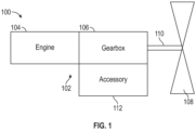
- an aircraft propulsion system 100 includes an engine assembly 102 including, for example, an engine 104 coupled to a reduction gearbox 106, which in turn is mechanically coupled to a propulsor, such as a propeller 108, via an output shaft 110.
- the engine 104 is a gas turbine engine.
- One or more accessory components 112, such as a generator, are coupled to the reduction gearbox 106, to allow for power extraction from the reduction gearbox 106.
- the one or more accessory components 112 include an electrical motor or emotor configured to supplement or replace power provided to the reduction gearbox 106 via the engine 104.
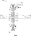
- the reduction gearbox 106 includes at least one epicyclic gear arrangement 114 (illustrated in FIGS. 2 , 4 and 5 ) to which the one or more accessory components 112 are mechanically coupled.
- the epicyclic gear arrangement 114 is a planetary system including a sun gear 116 mechanically coupled to an input shaft 118 through which rotational energy is provided from the engine 104.
- the sun gear 116 is meshed or otherwise engaged with a plurality of planet gears 120 arranged about a circumference of the sun gear 116.
- the plurality of planet gears 120 are connected to and supported by a planet carrier 122.
- the epicyclic gear arrangement 114 further includes a ring gear 124 disposed about an outer circumference of the plurality of planet gears 120 and is meshed or otherwise engaged with the plurality of planet gears 120.
- the ring gear 124 is rotationally fixed, such that rotational energy from the input shaft 118 is transferred through the sun gear 116, which rotates about a gearbox central axis 126 and into the plurality of planet gears 120.
- the plurality of planet gears 120 are thereby driven to rotate about their respective planet gear axes 128 and to further process about the gearbox central axis 126.
- This rotational energy is then transferred to the planet carrier 122, driving rotation of the planet carrier 122 about the gearbox central axis 126.
- the planet carrier 122 is mechanically coupled to the output shaft 110 to drive the propeller 108.
- the planet carrier 122 includes a planet bevel gear 130 located at an outer circumference of the planet carrier 122.
- the planet bevel gear 130 is engaged with an accessory bevel gear 132 to mechanical couple the accessory component 112 to the reduction gearbox 106.
- the planet bevel gear 130 and accessory bevel gear 132 directly couple the reduction gearbox 106 to the accessory component 112, while in other embodiments the reduction gearbox 106 is coupled to the accessory component 112 via an accessory gear train 134, as illustrated in FIGs. 3A and 3B .
- the planet bevel gear 130 is formed integral to the planet carrier 122, while in other embodiments the planet bevel gear 130 may be connected to the planet carrier 122 via a bolted connected with a plurality of bolts arrayed about a circumference of the planet carrier 122.
- the bolted connection is configured to reduce potential relative twist or circumferential motion between the planet carrier 122 and the planet bevel gear 130 to improve power transmission through the planet bevel gear 120 to the accessory bevel gear 132.
- the accessory bevel gear 132 is coupled to a first gear train shaft 136 and extends laterally in direction D
- the accessory gear train 134 then extends downwardly via a second gear train shaft 138 and engages with an accessory input gear 140 of the accessory component 112, which extends in parallel with direction D.
- the first gear train shaft 136 extends downwardly in direction D.
- the accessory gear train 134 then extends laterally via the second gear train shaft 138 and engages with the accessory input gear 140 of the accessory component 112, which extends in parallel with direction D.
- the epicyclic gear arrangement 114 is a star system.
- the planet carrier 122 is rotationally fixed relative to the gearbox central axis 126 and the ring gear 124 is configured to rotate about the gearbox central axis 126.
- the ring gear 124 includes a ring bevel gear 142 which is mechanically coupled to the accessory bevel gear 132.
- rotational energy is transferred from the input shaft 118 through the sun gear 116 and to the plurality of planet gears 120.
- the plurality of planet gears 120 rotate about their respective planet gear axes 128, driving rotation of the ring gear 124 about the gearbox central axis 126.
- the accessory component 112 is driven by the rotation of the accessory bevel gear 132, which is coupled to the ring gear 124 via the ring bevel gear 142.
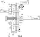
- FIG. 5 Another exemplary embodiment is illustrated in FIG. 5 , in which the epicyclic gear arrangement 114 has a solar arrangement.
- the input shaft 118 is coupled to the ring gear 124 and the sun gear 116 is rotationally fixed relative to the gearbox central axis 126.
- Rotational energy is transferred from the ring gear 124 to the plurality of planet gears 120.
- the plurality of planet gears 120 are thereby driven to rotate about their respective planet gear axes 128 and to further process about the gearbox central axis 126.
- This rotational energy is then transferred to the planet carrier 122, driving rotation of the planet carrier 122 about the gearbox central axis 126.
- the planet carrier 122 is mechanically coupled to the output shaft 110 to drive the propeller 108.
- the planet carrier 122 includes the planet bevel gear 130 located at the outer circumference of the planet carrier 122.
- the planet bevel gear 130 is engaged with the accessory bevel gear 132 to mechanical couple the accessory component 112 to the reduction gearbox 106
Landscapes
- Engineering & Computer Science (AREA)
- General Engineering & Computer Science (AREA)
- Mechanical Engineering (AREA)
- Chemical & Material Sciences (AREA)
- Combustion & Propulsion (AREA)
- Aviation & Aerospace Engineering (AREA)
- Retarders (AREA)
Abstract
A reduction gearbox (106) of an aircraft propulsion system (100) includes an input shaft (118) configured to input rotational energy into the reduction gearbox (106), an output shaft (110) configured to output rotational energy from the reduction gearbox (106) to a propulsor (108) of the aircraft propulsion system (100), and an epicyclic gear arrangement (114) mechanically coupling the output shaft (110) to the input shaft (118). A transfer gear (130; 142) is positioned at a component of the epicyclic gear arrangement (114) and is configured to mechanically couple an accessory component (112) to the reduction gearbox (106).
Description
- The present disclosure relates to aircraft engines and, more particularly, to high-power extraction from the aircraft engine and/or supplemental power input to the aircraft engine via externally mounted accessories.
- In an aircraft, gas turbine engines are used to turn propellors, fans and turboshafts during various flight operations. Gas turbine engines can also be used to drive generator operations. Additionally, supplemental power may be added to the motor or engine via an externally mounted accessory, such as an electric motor, also known as an emotor. In any case, a gearbox is typically provided and configured to take rotational energy as an input from the gas turbine engine and to transfer that rotational energy to an externally connected accessory, such as a generator.
- Such a connection is typically made at an output shaft of the gas turbine engine, but it is desired to make the gas turbine engine and accessory system more compact, especially in an axial direction, and connection at this location limits the ability to do so.
- In an aspect of the present invention, a reduction gearbox of an aircraft propulsion system includes an input shaft configured to input rotational energy into the reduction gearbox, an output shaft configured to output rotational energy from the reduction gearbox to a propulsor of the aircraft propulsion system, and an epicyclic gear arrangement mechanically coupling the output shaft to the input shaft. A transfer gear is positioned at a component of the epicyclic gear arrangement and is configured to mechanically couple an accessory component to the reduction gearbox.
- In an embodiment of the above, the transfer gear is positioned at a planet carrier of the epicyclic gear arrangement.
- In an embodiment according to any of the previous embodiments, the epicyclic gear arrangement is configured as one of a planetary arrangement or a solar arrangement.
- In an embodiment according to any of the previous embodiments, the transfer gear is positioned at a ring gear of the epicyclic gear arrangement.
- In an embodiment according to any of the previous embodiments, the transfer gear is a bevel gear positioned at an outer circumference of one of a planet carrier or a ring gear of the epicyclic gear arrangement.
- In another aspect of the present invention, a reduction gearbox and accessory component arrangement of an aircraft propulsion system includes a reduction gearbox including an input shaft configured to input rotational energy into the reduction gearbox, an output shaft configured to output rotational energy from the reduction gearbox to a propulsor of the aircraft propulsion system, and an epicyclic gear arrangement mechanically coupling the output shaft to the input shaft. A transfer gear is positioned at a component of the epicyclic gear arrangement. An accessory component is mechanically coupled to the epicyclic gear arrangement via the transfer gear to transmit rotational energy between the reduction gearbox and the accessory component.
- In an embodiment of the above, a component bevel gear is configured to mechanically couple the accessory component to the transfer gear.
- In an embodiment according to any of the previous embodiments, the transfer gear is positioned at a planet carrier of the epicyclic gear arrangement.
- In an embodiment according to any of the previous embodiments, the epicyclic gear arrangement is configured as one of a planetary arrangement or a solar arrangement.
- In an embodiment according to any of the previous embodiments, the transfer gear is positioned at a ring gear of the epicyclic gear arrangement.
- In an embodiment according to any of the previous embodiments, the transfer gear is a bevel gear positioned at an outer circumference of one of a planet carrier or a ring gear of the epicyclic gear arrangement.
- In an embodiment according to any of the previous embodiments, the accessory component is mechanically coupled to the transfer gear via a gear train including at least one gear train shaft.
- In an embodiment according to any of the previous embodiments, the at least on gear train shaft is two gear train shafts, including a first gear train shaft coupled to the transfer gear and extending in a first direction therefrom, and a second gear train shaft coupled to the first gear train shaft and extending from the first gear train shaft in a second direction different than the first direction.
- In an embodiment according to any of the previous embodiments, the accessory component is one of a generator or a motor.
- In yet another aspect of the present invention, a propulsion system of an aircraft includes an engine configured to provide rotational energy to a reduction gearbox. The reduction gearbox includes an input shaft configured to input rotational energy into the reduction gearbox, an output shaft configured to output rotational energy from the reduction gearbox to a propulsor of the aircraft propulsion system, and an epicyclic gear arrangement mechanically coupling the output shaft to the input shaft. A transfer gear is positioned at a component of the epicyclic gear arrangement, and an accessory component is mechanically coupled to the epicyclic gear arrangement via the transfer gear to transmit rotational energy between the reduction gearbox and the accessory component. A propulsor is operably connected to the output shaft and driven by rotation of the output shaft.
- In an embodiment of the above, a component bevel gear is configured to mechanically couple the accessory component to the transfer gear.
- In an embodiment according to any of the previous embodiments, the transfer gear is positioned at a planet carrier of the epicyclic gear arrangement.
- In an embodiment according to any of the previous embodiments, the epicyclic gear arrangement is configured as one of a planetary arrangement or a solar arrangement.
- In an embodiment according to any of the previous embodiments, the transfer gear is positioned at a ring gear of the epicyclic gear arrangement.
- In an embodiment according to any of the previous embodiments, the transfer gear is a bevel gear positioned at an outer circumference of one of a planet carrier or a ring gear of the epicyclic gear arrangement.
- Additional features and advantages are realized through the techniques of the present disclosure. Other embodiments and aspects of the disclosure are described in detail herein and are considered a part of the claimed technical concept. For a better understanding of the disclosure with the advantages and the features, refer to the description and to the drawings.
- For a more complete understanding of this disclosure, reference is now made to the following brief description, taken in connection with the accompanying drawings and detailed description, wherein like reference numerals represent like parts:
-
FIG. 1 is a schematic illustration of an embodiment of a propulsion system of an aircraft; -
FIG. 2 is a schematic illustration of an embodiment of an epicyclic gear arrangement of a reduction gearbox including a transfer gear; -
FIGS. 3A and 3B are schematic illustrations of an aircraft motor assembly in which a gear train and an accessory component have multiple orientations in accordance with embodiments; -
FIG. 4 is a schematic illustration of another embodiment of an epicyclic gear arrangement of a reduction gearbox including a transfer gear; and -
FIG. 5 is a schematic illustration of yet another embodiment of an epicyclic gear arrangement of a reduction gearbox including a transfer gear. - As will be described below, an aircraft engine, such as a gas turbine engine, has a reduction gearbox installed thereto including a high-power bevel gear that can be matched to a single branch triple reduction (SBTR) component for power extraction or hybrid mode. The SBTR component provides a wide range of potential speed adjustments to reach a required speed at the output from the available power gear speeds. An external accessory, such as an electrical generator or the like, is mechanically coupled to the reduction gearbox system at, for example, a planet carrier or a ring gear of the reduction gearbox system.
- With reference to
FIG. 1 , anaircraft propulsion system 100 includes anengine assembly 102 including, for example, anengine 104 coupled to areduction gearbox 106, which in turn is mechanically coupled to a propulsor, such as apropeller 108, via anoutput shaft 110. In some embodiments, theengine 104 is a gas turbine engine. One ormore accessory components 112, such as a generator, are coupled to thereduction gearbox 106, to allow for power extraction from thereduction gearbox 106. Additionally or alternatively the one ormore accessory components 112 include an electrical motor or emotor configured to supplement or replace power provided to thereduction gearbox 106 via theengine 104. Thereduction gearbox 106 includes at least one epicyclic gear arrangement 114 (illustrated inFIGS. 2 ,4 and5 ) to which the one ormore accessory components 112 are mechanically coupled. - Referring now to
FIG. 2 , in one exemplary embodiment theepicyclic gear arrangement 114 is a planetary system including asun gear 116 mechanically coupled to aninput shaft 118 through which rotational energy is provided from theengine 104. Thesun gear 116 is meshed or otherwise engaged with a plurality ofplanet gears 120 arranged about a circumference of thesun gear 116. The plurality ofplanet gears 120 are connected to and supported by aplanet carrier 122. Theepicyclic gear arrangement 114 further includes aring gear 124 disposed about an outer circumference of the plurality ofplanet gears 120 and is meshed or otherwise engaged with the plurality ofplanet gears 120. In this planetary system, thering gear 124 is rotationally fixed, such that rotational energy from theinput shaft 118 is transferred through thesun gear 116, which rotates about a gearboxcentral axis 126 and into the plurality ofplanet gears 120. The plurality ofplanet gears 120 are thereby driven to rotate about their respectiveplanet gear axes 128 and to further process about the gearboxcentral axis 126. This rotational energy is then transferred to theplanet carrier 122, driving rotation of theplanet carrier 122 about the gearboxcentral axis 126. Theplanet carrier 122 is mechanically coupled to theoutput shaft 110 to drive thepropeller 108. - The
planet carrier 122 includes aplanet bevel gear 130 located at an outer circumference of theplanet carrier 122. Theplanet bevel gear 130 is engaged with anaccessory bevel gear 132 to mechanical couple theaccessory component 112 to thereduction gearbox 106. In some embodiments, theplanet bevel gear 130 andaccessory bevel gear 132 directly couple thereduction gearbox 106 to theaccessory component 112, while in other embodiments thereduction gearbox 106 is coupled to theaccessory component 112 via anaccessory gear train 134, as illustrated inFIGs. 3A and 3B . In some embodiments, theplanet bevel gear 130 is formed integral to theplanet carrier 122, while in other embodiments theplanet bevel gear 130 may be connected to theplanet carrier 122 via a bolted connected with a plurality of bolts arrayed about a circumference of theplanet carrier 122. The bolted connection is configured to reduce potential relative twist or circumferential motion between theplanet carrier 122 and theplanet bevel gear 130 to improve power transmission through theplanet bevel gear 120 to theaccessory bevel gear 132. - With reference to
FIGS. 3A and 3B , examples of multiple orientations of theaccessory gear train 134 are illustrated. As shown inFIG. 3A , theaccessory bevel gear 132 is coupled to a firstgear train shaft 136 and extends laterally in direction D Theaccessory gear train 134 then extends downwardly via a secondgear train shaft 138 and engages with anaccessory input gear 140 of theaccessory component 112, which extends in parallel with direction D. In another embodiment as illustrated inFIG. 3B , the firstgear train shaft 136 extends downwardly in direction D. Theaccessory gear train 134 then extends laterally via the secondgear train shaft 138 and engages with theaccessory input gear 140 of theaccessory component 112, which extends in parallel with direction D. - Referring now to
FIG. 4 , in another exemplary embodiment theepicyclic gear arrangement 114 is a star system. In the star arrangement, theplanet carrier 122 is rotationally fixed relative to the gearboxcentral axis 126 and thering gear 124 is configured to rotate about the gearboxcentral axis 126. In this configuration, thering gear 124 includes aring bevel gear 142 which is mechanically coupled to theaccessory bevel gear 132. In this embodiment, rotational energy is transferred from theinput shaft 118 through thesun gear 116 and to the plurality of planet gears 120. The plurality of planet gears 120 rotate about their respective planet gear axes 128, driving rotation of thering gear 124 about the gearboxcentral axis 126. Theaccessory component 112 is driven by the rotation of theaccessory bevel gear 132, which is coupled to thering gear 124 via thering bevel gear 142. - Another exemplary embodiment is illustrated in
FIG. 5 , in which theepicyclic gear arrangement 114 has a solar arrangement. In the solar arrangement, theinput shaft 118 is coupled to thering gear 124 and thesun gear 116 is rotationally fixed relative to the gearboxcentral axis 126. Rotational energy is transferred from thering gear 124 to the plurality of planet gears 120. The plurality of planet gears 120 are thereby driven to rotate about their respective planet gear axes 128 and to further process about the gearboxcentral axis 126. This rotational energy is then transferred to theplanet carrier 122, driving rotation of theplanet carrier 122 about the gearboxcentral axis 126. Theplanet carrier 122 is mechanically coupled to theoutput shaft 110 to drive thepropeller 108. Theplanet carrier 122 includes theplanet bevel gear 130 located at the outer circumference of theplanet carrier 122. Theplanet bevel gear 130 is engaged with theaccessory bevel gear 132 to mechanical couple theaccessory component 112 to thereduction gearbox 106. - Technical effects and benefits of the present disclosure are the provision of a reduction gearbox of an aircraft propulsion system in which one or more accessory components are mechanically connected to an epicyclic gear arrangement of the reduction gearbox. This configuration allows for reduction of an axial length of such arrangements compared to traditional arrangements where the accessory components are mechanically coupled to an output shaft of the reduction gearbox.
- The terminology used herein is for the purpose of describing particular embodiments only and is not intended to be limiting of the present disclosure. As used herein, the singular forms "a", "an" and "the" are intended to include the plural forms as well, unless the context clearly indicates otherwise. It will be further understood that the terms "comprises" and/or "comprising," when used in this specification, specify the presence of stated features, integers, steps, operations, elements, and/or components, but do not preclude the presence or addition of one or more other features, integers, steps, operations, element components, and/or groups thereof.
- While the present disclosure has been described with reference to an exemplary embodiment or embodiments, it will be understood by those skilled in the art that various changes may be made and equivalents may be substituted for elements thereof without departing from the scope of the present disclosure. In addition, many modifications may be made to adapt a particular situation or material to the teachings of the present disclosure without departing from the essential scope thereof. Therefore, it is intended that the present disclosure not be limited to the particular embodiment disclosed as the best mode contemplated for carrying out this present disclosure, but that the present disclosure will include all embodiments falling within the scope of the claims.
Claims (15)
- A reduction gearbox (106) for an aircraft propulsion system (100), comprising:an input shaft (118) configured to input rotational energy into the reduction gearbox (106);an output shaft (110) configured to output rotational energy from the reduction gearbox (106) to a propulsor (108) of the aircraft propulsion system (100);an epicyclic gear arrangement (114) mechanically coupling the output shaft (110) to the input shaft (118);a transfer gear (130; 142) disposed at a component of the epicyclic gear arrangement (114) and configured to mechanically couple an accessory component (112) to the reduction gearbox (106).
- The reduction gearbox of claim 1, wherein the transfer gear (130) is disposed at a planet carrier (122) of the epicyclic gear arrangement (114).
- The reduction gearbox of claim 1 or 2, wherein the epicyclic gear arrangement (114) is configured as one of a planetary arrangement or a solar arrangement.
- The reduction gearbox of claim 1, wherein the transfer gear (142) is disposed at a ring gear (124) of the epicyclic gear arrangement (114).
- The reduction gearbox of claim 1, wherein the transfer gear (130; 142) is a bevel gear (130; 142) disposed at an outer circumference of one of a planet carrier (122) or a ring gear (124) of the epicyclic gear arrangement (114).
- A reduction gearbox and accessory component arrangement for an aircraft propulsion system (100), comprising:the reduction gearbox (106) of claim 1; andan accessory component (112) mechanically coupled to the epicyclic gear arrangement (114) via the transfer gear (130; 142) to transmit rotational energy between the reduction gearbox (106) and the accessory component (112).
- The reduction gearbox and accessory component arrangement of claim 6, further comprising a component bevel gear (132) configured to mechanically couple the accessory component (112) to the transfer gear (130; 142).
- The reduction gearbox and accessory component arrangement of claim 6 or 7, wherein the transfer gear (130) is disposed at a planet carrier (122) of the epicyclic gear arrangement (114).
- The reduction gearbox and accessory component arrangement of claim 6, 7 or 8, wherein the epicyclic gear arrangement (114) is configured as one of a planetary arrangement or a solar arrangement.
- The reduction gearbox and accessory component arrangement of claim 6 or 7, wherein the transfer gear (142) is disposed at a ring gear (124) of the epicyclic gear arrangement (114).
- The reduction gearbox and accessory component arrangement of claim 6 or 7, wherein the transfer gear (130; 142) is a bevel gear (130; 142) disposed at an outer circumference of one of a planet carrier (122) or a ring gear (124) of the epicyclic gear arrangement (114).
- The reduction gearbox and accessory component arrangement of any of claims 6 to 11, wherein the accessory component (112) is mechanically coupled to the transfer gear (130; 142) via a gear train (134) including at least one gear train shaft (136, 138).
- The reduction gearbox and accessory component arrangement of claim 12, wherein the at least on gear train shaft (136, 138) is two gear train shafts, including:a first gear train shaft (136) coupled to the transfer gear (130; 142) and extending in a first direction therefrom; anda second gear train shaft (138) coupled to the first gear train shaft (136) and extending from the first gear train shaft (136) in a second direction different than the first direction.
- The reduction gearbox and accessory component arrangement of any of claims 6 to 13, wherein the accessory component (112) is one of a generator or a motor.
- A propulsion system (100) of an aircraft, comprising:the reduction gearbox and accessory component arrangement of any of claims 6 to 14;an engine (104) configured to provide rotational energy to the reduction gearbox (106); anda propulsor (108) operably connected to the output shaft (110) and driven by rotation of the output shaft (110).
Applications Claiming Priority (1)
| Application Number | Priority Date | Filing Date | Title |
|---|---|---|---|
| US18/533,770 US12460706B2 (en) | 2023-12-08 | 2023-12-08 | Epicyclic system with bevel attachment for dual-power applications |
Publications (1)
| Publication Number | Publication Date |
|---|---|
| EP4567302A1 true EP4567302A1 (en) | 2025-06-11 |
Family
ID=93843318
Family Applications (1)
| Application Number | Title | Priority Date | Filing Date |
|---|---|---|---|
| EP24218414.1A Pending EP4567302A1 (en) | 2023-12-08 | 2024-12-09 | Epicyclic system with bevel attachment for dual-power applications |
Country Status (2)
| Country | Link |
|---|---|
| US (1) | US12460706B2 (en) |
| EP (1) | EP4567302A1 (en) |
Citations (3)
| Publication number | Priority date | Publication date | Assignee | Title |
|---|---|---|---|---|
| WO2008044972A1 (en) * | 2006-10-13 | 2008-04-17 | Volvo Aero Corporation | A device for retrieval of power from a gas turbine engine, and a gas turbine engine |
| US11041462B2 (en) * | 2019-06-05 | 2021-06-22 | Raytheon Technologies Corporation | Hybrid turbofan with differential electrical and mechanical power transfer |
| DE102021110412A1 (en) * | 2020-04-27 | 2021-10-28 | Steering Solutions Ip Holding Corporation | DOUBLE MOTOR DOUBLE REVERSING GEAR WITH COUPLED WHEEL WITH EXTERNAL TEETH |
Family Cites Families (8)
| Publication number | Priority date | Publication date | Assignee | Title |
|---|---|---|---|---|
| US3939735A (en) | 1974-04-18 | 1976-02-24 | Power-Flo Products, Inc. | Double epicyclic transmission structure |
| US5152668A (en) | 1990-07-23 | 1992-10-06 | General Electric Company | Pitch change mechanism for prop fans |
| AUPP433198A0 (en) | 1998-06-25 | 1998-07-16 | Aimbridge Pty Ltd | A motor for driving a propeller including a phase adjuster for altering the pitch of the propeller blades |
| US6663530B2 (en) | 2001-12-14 | 2003-12-16 | Pratt & Whitney Canada Corp. | Zero twist carrier |
| US11022043B2 (en) * | 2015-10-05 | 2021-06-01 | Safran Aircraft Engines | Turbine engine with fan and reduction of speed on the shaft of the power turbine |
| US10273883B2 (en) | 2016-02-26 | 2019-04-30 | The Boeing Company | Engine accessory drives systems and methods |
| US20170284524A1 (en) | 2016-03-31 | 2017-10-05 | Schaeffler Technologies AG & Co. KG | Bevel ring gear with integrated planetary differential |
| US10823006B2 (en) * | 2019-03-14 | 2020-11-03 | Raytheon Technologies Corporation | Lubrication systems and methods with superposition gearbox |
-
2023
- 2023-12-08 US US18/533,770 patent/US12460706B2/en active Active
-
2024
- 2024-12-09 EP EP24218414.1A patent/EP4567302A1/en active Pending
Patent Citations (3)
| Publication number | Priority date | Publication date | Assignee | Title |
|---|---|---|---|---|
| WO2008044972A1 (en) * | 2006-10-13 | 2008-04-17 | Volvo Aero Corporation | A device for retrieval of power from a gas turbine engine, and a gas turbine engine |
| US11041462B2 (en) * | 2019-06-05 | 2021-06-22 | Raytheon Technologies Corporation | Hybrid turbofan with differential electrical and mechanical power transfer |
| DE102021110412A1 (en) * | 2020-04-27 | 2021-10-28 | Steering Solutions Ip Holding Corporation | DOUBLE MOTOR DOUBLE REVERSING GEAR WITH COUPLED WHEEL WITH EXTERNAL TEETH |
Also Published As
| Publication number | Publication date |
|---|---|
| US20250189022A1 (en) | 2025-06-12 |
| US12460706B2 (en) | 2025-11-04 |
Similar Documents
| Publication | Publication Date | Title |
|---|---|---|
| EP3941830B1 (en) | Architectures for hybrid-electric propulsion | |
| EP2977315B1 (en) | Apparatus and methods for powering an electrical device associated with an aircraft rotor | |
| GB2612426A (en) | Aircraft turbine with an off-axis propellor | |
| US5807202A (en) | Differential speed transmission | |
| US11319882B2 (en) | Gear and electric amplification of generator motor compressor and turbine drives | |
| EP3910174B1 (en) | Reverse-flow gas turbine engine with electric motor | |
| US8075438B2 (en) | Apparatus and method for transmitting a rotary input into counter-rotating outputs | |
| CN113710575B (en) | Especially for the drive of the main rotor of a rotary-wing aircraft | |
| US12196139B2 (en) | Speed reducer equipped with an electric machine | |
| CN113251111A (en) | Gearbox assembly with electric motor | |
| EP3722577B1 (en) | Variable multiple-drive gas turbine engine | |
| US20050000224A1 (en) | Gas turbine arrangement | |
| EP3569507B1 (en) | Aircraft propulsion system | |
| US12163477B2 (en) | Turbomachine comprising a speed reduction gear and at least one electric machine | |
| EP4471265A3 (en) | Inter-rotating assembly power coupling system for turbine engine | |
| US12460706B2 (en) | Epicyclic system with bevel attachment for dual-power applications | |
| WO2008044972A1 (en) | A device for retrieval of power from a gas turbine engine, and a gas turbine engine | |
| EP1295788B1 (en) | Hybrid power input quill for transmissions | |
| CA3255310A1 (en) | Epicyclic system with bevel attachment for dual-power applications | |
| US12516634B2 (en) | Turbomachine comprising a speed reduction gear integrating an electric machine | |
| EP4525278A1 (en) | Integrated gear motor | |
| US20250392192A1 (en) | Electric drive unit for a vehicle | |
| US12179933B1 (en) | Electromechanically controlled aircraft power transmission system | |
| RU2802265C2 (en) | Drive, in particular for the main rotor of an aircraft with a main rotor | |
| JP2025122811A (en) | Aircraft propulsion systems |
Legal Events
| Date | Code | Title | Description |
|---|---|---|---|
| PUAI | Public reference made under article 153(3) epc to a published international application that has entered the european phase |
Free format text: ORIGINAL CODE: 0009012 |
|
| STAA | Information on the status of an ep patent application or granted ep patent |
Free format text: STATUS: THE APPLICATION HAS BEEN PUBLISHED |
|
| AK | Designated contracting states |
Kind code of ref document: A1 Designated state(s): AL AT BE BG CH CY CZ DE DK EE ES FI FR GB GR HR HU IE IS IT LI LT LU LV MC ME MK MT NL NO PL PT RO RS SE SI SK SM TR |
|
| STAA | Information on the status of an ep patent application or granted ep patent |
Free format text: STATUS: REQUEST FOR EXAMINATION WAS MADE |
|
| 17P | Request for examination filed |
Effective date: 20251209 |