EP4567273A1 - Method for obtaining an improved segmented blade - Google Patents
Method for obtaining an improved segmented blade Download PDFInfo
- Publication number
- EP4567273A1 EP4567273A1 EP22953893.9A EP22953893A EP4567273A1 EP 4567273 A1 EP4567273 A1 EP 4567273A1 EP 22953893 A EP22953893 A EP 22953893A EP 4567273 A1 EP4567273 A1 EP 4567273A1
- Authority
- EP
- European Patent Office
- Prior art keywords
- blade
- obtaining
- joint
- loads
- improved segmented
- Prior art date
- Legal status (The legal status is an assumption and is not a legal conclusion. Google has not performed a legal analysis and makes no representation as to the accuracy of the status listed.)
- Pending
Links
Images

Classifications
-
- F—MECHANICAL ENGINEERING; LIGHTING; HEATING; WEAPONS; BLASTING
- F03—MACHINES OR ENGINES FOR LIQUIDS; WIND, SPRING, OR WEIGHT MOTORS; PRODUCING MECHANICAL POWER OR A REACTIVE PROPULSIVE THRUST, NOT OTHERWISE PROVIDED FOR
- F03D—WIND MOTORS
- F03D1/00—Wind motors with rotation axis substantially parallel to the air flow entering the rotor
- F03D1/06—Rotors
- F03D1/065—Rotors characterised by their construction elements
- F03D1/0675—Rotors characterised by their construction elements of the blades
- F03D1/0677—Longitudinally segmented blades; Connectors therefor
-
- F—MECHANICAL ENGINEERING; LIGHTING; HEATING; WEAPONS; BLASTING
- F03—MACHINES OR ENGINES FOR LIQUIDS; WIND, SPRING, OR WEIGHT MOTORS; PRODUCING MECHANICAL POWER OR A REACTIVE PROPULSIVE THRUST, NOT OTHERWISE PROVIDED FOR
- F03D—WIND MOTORS
- F03D1/00—Wind motors with rotation axis substantially parallel to the air flow entering the rotor
- F03D1/06—Rotors
- F03D1/0608—Rotors characterised by their aerodynamic shape
- F03D1/0633—Rotors characterised by their aerodynamic shape of the blades
- F03D1/0641—Rotors characterised by their aerodynamic shape of the blades of the section profile of the blades, i.e. aerofoil profile
-
- F—MECHANICAL ENGINEERING; LIGHTING; HEATING; WEAPONS; BLASTING
- F03—MACHINES OR ENGINES FOR LIQUIDS; WIND, SPRING, OR WEIGHT MOTORS; PRODUCING MECHANICAL POWER OR A REACTIVE PROPULSIVE THRUST, NOT OTHERWISE PROVIDED FOR
- F03D—WIND MOTORS
- F03D1/00—Wind motors with rotation axis substantially parallel to the air flow entering the rotor
- F03D1/06—Rotors
- F03D1/065—Rotors characterised by their construction elements
- F03D1/0675—Rotors characterised by their construction elements of the blades
-
- F—MECHANICAL ENGINEERING; LIGHTING; HEATING; WEAPONS; BLASTING
- F05—INDEXING SCHEMES RELATING TO ENGINES OR PUMPS IN VARIOUS SUBCLASSES OF CLASSES F01-F04
- F05B—INDEXING SCHEME RELATING TO WIND, SPRING, WEIGHT, INERTIA OR LIKE MOTORS, TO MACHINES OR ENGINES FOR LIQUIDS COVERED BY SUBCLASSES F03B, F03D AND F03G
- F05B2230/00—Manufacture
- F05B2230/20—Manufacture essentially without removing material
- F05B2230/23—Manufacture essentially without removing material by permanently joining parts together
-
- F—MECHANICAL ENGINEERING; LIGHTING; HEATING; WEAPONS; BLASTING
- F05—INDEXING SCHEMES RELATING TO ENGINES OR PUMPS IN VARIOUS SUBCLASSES OF CLASSES F01-F04
- F05B—INDEXING SCHEME RELATING TO WIND, SPRING, WEIGHT, INERTIA OR LIKE MOTORS, TO MACHINES OR ENGINES FOR LIQUIDS COVERED BY SUBCLASSES F03B, F03D AND F03G
- F05B2230/00—Manufacture
- F05B2230/50—Building or constructing in particular ways
- F05B2230/502—Building or constructing in particular ways using existing or "off the shelf" parts, e.g. using standardised turbocharger elements
-
- F—MECHANICAL ENGINEERING; LIGHTING; HEATING; WEAPONS; BLASTING
- F05—INDEXING SCHEMES RELATING TO ENGINES OR PUMPS IN VARIOUS SUBCLASSES OF CLASSES F01-F04
- F05B—INDEXING SCHEME RELATING TO WIND, SPRING, WEIGHT, INERTIA OR LIKE MOTORS, TO MACHINES OR ENGINES FOR LIQUIDS COVERED BY SUBCLASSES F03B, F03D AND F03G
- F05B2230/00—Manufacture
- F05B2230/80—Repairing, retrofitting or upgrading methods
-
- F—MECHANICAL ENGINEERING; LIGHTING; HEATING; WEAPONS; BLASTING
- F05—INDEXING SCHEMES RELATING TO ENGINES OR PUMPS IN VARIOUS SUBCLASSES OF CLASSES F01-F04
- F05B—INDEXING SCHEME RELATING TO WIND, SPRING, WEIGHT, INERTIA OR LIKE MOTORS, TO MACHINES OR ENGINES FOR LIQUIDS COVERED BY SUBCLASSES F03B, F03D AND F03G
- F05B2240/00—Components
- F05B2240/20—Rotors
- F05B2240/30—Characteristics of rotor blades, i.e. of any element transforming dynamic fluid energy to or from rotational energy and being attached to a rotor
- F05B2240/302—Segmented or sectional blades
-
- Y—GENERAL TAGGING OF NEW TECHNOLOGICAL DEVELOPMENTS; GENERAL TAGGING OF CROSS-SECTIONAL TECHNOLOGIES SPANNING OVER SEVERAL SECTIONS OF THE IPC; TECHNICAL SUBJECTS COVERED BY FORMER USPC CROSS-REFERENCE ART COLLECTIONS [XRACs] AND DIGESTS
- Y02—TECHNOLOGIES OR APPLICATIONS FOR MITIGATION OR ADAPTATION AGAINST CLIMATE CHANGE
- Y02P—CLIMATE CHANGE MITIGATION TECHNOLOGIES IN THE PRODUCTION OR PROCESSING OF GOODS
- Y02P70/00—Climate change mitigation technologies in the production process for final industrial or consumer products
- Y02P70/50—Manufacturing or production processes characterised by the final manufactured product
Definitions
- the present invention falls within the field of segmented wind turbine blades, more particularly, in the development of an agile and effective methodology for blade design that allows groups of segmented blades to be optimized and launched onto the market in minimum time and cost.
- patent WO2009135902 describes how to change the blade tip by sizing the blade loads with the longer tip and patent US200702553824 describes how to exchange the tip and then infuse it inside the beam.
- the solution presented differs from the state of the art since it is specifically defined for the mass optimization and AEP (annual energy production) of modular blades, which will be essential from now on for logistical reasons. To do this, the chord is reduced, reducing the load and the AEP indirectly. To recover the lost AEP, the length of the blade is extended at its tip.
- the basis of the invention is to apply these design techniques respecting the geometric restrictions required to optimize the use of the same production means for the entire group of blades and the adaptation of existing moulds to incorporate the minimum changes in the production lines.
- the present invention contemplates different actions along the blade.
- the section In the area where the joint is made, the section must be as thick as possible to have a reaction arm with which to reduce unit loads for a moment in the given section.
- Another object of the invention is to adapt existing moulds for the manufacture of these new blades.
- the core of the invention lies in the methodology that allows the ideal combination of these techniques to obtain an optimal modular blade.
- the modular blade has a connection point (1) and consists of two modules: inboard module (2), between the blade root and the connection with a length L inboard , and outboard module (3), between the connection and the blade tip with a length L outboard . Adding both lengths mentioned above gives the total length of the blade L blade .
- the mass and cost of the same depends on the loads of the section (4) and its geometry.
- the unit loads in the connection elements (5) depend on the load to be supported in said section (4) and its geometry.
- a thick blade reacts to the load or moment with a lower unit load due to having a greater reaction arm and a thin blade reacts to the load or moment with a greater unit load due to having a smaller reaction arm.
- the resulting mass and cost of the joint basically depend on this unit load on the connecting elements (5). Therefore, it will be of vital importance to reduce this unit load on the connecting elements (5) as much as possible.
- chord distribution (6A) for the standard version and (7A) for the slender version and thicknesses (6B) for the standard version and (7B) for the slender version for a standard 95m blade and a slender configuration built from said blade, wherein:
- This slender has a disadvantage, which is the loss of power output (AEP) by the machine.
- AEP loss of power output
- This 6% reduction in the joint area allows the number of joint elements (5) to be reduced from 10 to 8 per cap, reducing the mass from 800kg to 640kg, with its associated reduction in cost. This reduction in elements is greater than the reduction in loads since the eliminated elements are the least efficient and barely increase the joint load step by the 6% that has been reduced.
- the common mould for the standard blade version and for the slender blade version is longer.
- the outboard mould has inserts to make the standard modular blade and the slender modular blade.
- the mould has to be the envelope of the two types of blades: the standard and the slender.
- the same mould is used for both types of blades.
- the mould for the standard blade does not vary except for the last two metres, which have more string. That is why in the CC' section the removable insert is in the standard version.
- the slender version is longer and thinner, the removable inserts are placed in the AA' and BB' sections.
Landscapes
- Engineering & Computer Science (AREA)
- Life Sciences & Earth Sciences (AREA)
- Sustainable Development (AREA)
- Sustainable Energy (AREA)
- Chemical & Material Sciences (AREA)
- Combustion & Propulsion (AREA)
- Mechanical Engineering (AREA)
- General Engineering & Computer Science (AREA)
- Physics & Mathematics (AREA)
- Fluid Mechanics (AREA)
- Wind Motors (AREA)
Abstract
a) the chord and overall thickness in the 20 m of the outboard module (3) are reduced by 75%;
b) the outboard module (3) is extended by 1 m;
c) joining elements (5) per cap are reduced from 10 to 8, and the blade mass from 800 kg to 640 kg, reducing the impact for the joint mass on the rest of the wind turbine; and
d) loads at the blade root are reduced by 11% without affecting wind turbine productivity.
Description
- The present invention falls within the field of segmented wind turbine blades, more particularly, in the development of an agile and effective methodology for blade design that allows groups of segmented blades to be optimized and launched onto the market in minimum time and cost.
- Given the constant evolution in terms of requirements for new generations of machines and their components, there is a need for manufacturers in the wind sector to continually adapt to the growth of blade groups. It is crucial to facilitate the transition to longer blades that can be transported, maintain a competitive cost and limit investments in production resources as much as possible.
- To this end, a methodology is being developed that allows the development and manufacturing process of modular blades to be standardised as much as possible, and which, with a minimum impact on the initial models, largely enables the use of the production lines already available.
- There are solutions for blades with interchangeable tips. Thus, patent
WO2009135902 describes how to change the blade tip by sizing the blade loads with the longer tip and patentUS200702553824 - On the other hand, there is the design possibility of varying the aerodynamic profile of the blade. RISO and TUF present patents
WO01/14740 EP 2275671 , modifying the lift with the variation of the blade profile and presenting an analytical design methodology mapping the blade profile. - The solution presented differs from the state of the art since it is specifically defined for the mass optimization and AEP (annual energy production) of modular blades, which will be essential from now on for logistical reasons. To do this, the chord is reduced, reducing the load and the AEP indirectly. To recover the lost AEP, the length of the blade is extended at its tip. The basis of the invention is to apply these design techniques respecting the geometric restrictions required to optimize the use of the same production means for the entire group of blades and the adaptation of existing moulds to incorporate the minimum changes in the production lines.
- One of the impacts of blade modularization is the increase in loads that can be induced by the excess weight implied by the modular union. Therefore, it is logically advisable to reduce the mass and cost of the union as much as possible without harming the AEP. To this end, the present invention contemplates different actions along the blade. In the area where the joint is made, the section must be as thick as possible to have a reaction arm with which to reduce unit loads for a moment in the given section.
- In the tip area, the chord and thickness of the blade are reduced in order to reduce the loads in the joining section. This "thinning" has the disadvantage of a certain loss of AEP. In order to recover the lost AEP, the length of the blade is lengthened at the tip.
- It is an object of the invention to reduce the tip chord of the blade, reducing loads and production compared to the nominal blade configuration.
- It is another object of the invention to lengthen the outboard module, recovering production without impacting loads so much as to recover what was gained at the previous point.
- Another object of the invention is to adapt existing moulds for the manufacture of these new blades.
- The advantages are the following:
This concept, which could be adopted in a non-modular blade design, is not as effective as in a modular blade, since lengthening the blade seriously impacts logistics costs, which does not occur in a modular blade since the outboard module (which is the one that is lengthened) does not have a Loutboard greater than 30m. - The core of the invention lies in the methodology that allows the ideal combination of these techniques to obtain an optimal modular blade.
- A brief description will be given below for a series of drawings useful for better understanding the invention and that expressly relate to an embodiment of said invention that is presented as a non-limiting example thereof.
-
Figure 1 shows a modular blade with the two modules. -
Figure 2 shows how the bending loads (dimensioning factor) in the joint section react in unitary elementary loads in the different elements that make up the joint. -
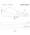
Figure 3 shows the distribution of chords and thicknesses of the reference blade (standard version) and the eventual modifications that can be applied to it (slender version). -
Figure 4 shows the plan view (chords) and elevation (thicknesses) of the reference blade. -
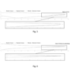
Figure 5 shows the plan view (chords) of the reference blade (standard), the chord reduction modification (slender) and the length extension modification (slender+extension) as well as a detail of the area that includes these modifications. -
Figure 6 shows the elevation view (thicknesses) of the reference blade (standard), the chord reduction modification (slender) and the length extension modification (slender+extension) as well as a detail of the area that includes these modifications. -
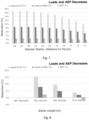
Figure 7 shows the impact on loads and AEP due to the thinning effect as a function of the thinning start position. -
Figure 8 shows the impact on loads and AEP for a blade configuration with thinning selected due to the increase in blade length. -
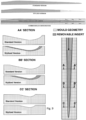
Figure 9 shows the mould used and the different outboard module combinations. - As shown in
Figure 1 , the modular blade has a connection point (1) and consists of two modules: inboard module (2), between the blade root and the connection with a length Linboard, and outboard module (3), between the connection and the blade tip with a length Loutboard. Adding both lengths mentioned above gives the total length of the blade Lblade. - As shown in
Figure 2 , whatever the connection concept, the mass and cost of the same depends on the loads of the section (4) and its geometry. Specifically, the unit loads in the connection elements (5) depend on the load to be supported in said section (4) and its geometry. Thus, a thick blade reacts to the load or moment with a lower unit load due to having a greater reaction arm and a thin blade reacts to the load or moment with a greater unit load due to having a smaller reaction arm. The resulting mass and cost of the joint basically depend on this unit load on the connecting elements (5). Therefore, it will be of vital importance to reduce this unit load on the connecting elements (5) as much as possible. - Since the joint (1) is a metal joint, for a modular blade of Lblade = 95m, with a joint 25-30m from the tip, this implies an increase in the load on the blade root of around 8%-10%, which means a redesign of wind turbine components (including the inboard module (2) of the blade).
- To alleviate this overload, a slender or "slimming" of the outboard module (3) of the blade is generated, reducing the chord/thickness of the geometry, as shown in
figure 3 and figure 4 . - In this
figure 3 , it is possible to see a chord distribution (6A) for the standard version and (7A) for the slender version and thicknesses (6B) for the standard version and (7B) for the slender version, for a standard 95m blade and a slender configuration built from said blade, wherein: - a) The chord is reduced to 75% for the last 20m of the tip.
- b) A transition of another 15m is defined to adapt to the original chords of the standard blade.
- c) The distribution of relative thicknesses is maintained, which leads to an identical reduction to that of chords in the overall thicknesses.
- This slender has two effects:
- a) Direct reduction of loads at the blade root
- b) Direct reduction of loads in the joint area which implies a reduction of the joint and therefore of its impact on loads at the blade root.
- This slender has a disadvantage, which is the loss of power output (AEP) by the machine. This is solved by lengthening the length of the outboard module (3), as shown in the images in
figure 5 (chords) andfigure 6 (thicknesses), which implies the recovery of production in exchange for losing some improvement in loads. - This method, slender + extension, allows:
- a) Absorbing load increases induced by modularization
- b) Allowing optimization of the aerodynamic blade design without the restriction of blade length.
- c) Having groups of blades for different locations with:
- i. Same inboard module (2)
- ii. Different outboard modules (3) to raise AEP or lower loads depending on the location, with the same manufacturing costs of the inboard module (2), which represents 80% of the blade cost, and with the only investments of outboard modules (3) (which are much lower than those of inboard).
- d) No need to redesign components to absorb increased loads, having the possibility of modularizing wind turbine rotors in the closed design phase.
- e) No need to redesign joints to achieve larger rotors for the same wind turbine.
- As an example,
Figures 7 and 8 include the results of applying this procedure for a blade of Lblade = 95m: - STEP 1:
Figure 7 includes results of the Root Joint loads (RJ) and joint loads (loads in MBJ Modular Blade Joint elements) based on the selected slender station and for a chord reduction of 75%. Likewise, for each of the configurations the associated reduction in annual energy production (AEP) is included. - STEP 2: A configuration from those presented in
Figure 7 is selected, in this case the configuration with constant slender (chord reduction of 75%) from the station located 20m from the tip. This configuration is included in the images infigures 3, 4 ,5 and 6 . From this configuration, the extension study is carried out, including its results infigure 8 . As can be seen in this figure, with an extension of 1m, all the lost AEP is recovered, with a reduction in root loads of 11.5% and 6% in the joint area. - This 6% reduction in the joint area allows the number of joint elements (5) to be reduced from 10 to 8 per cap, reducing the mass from 800kg to 640kg, with its associated reduction in cost. This reduction in elements is greater than the reduction in loads since the eliminated elements are the least efficient and barely increase the joint load step by the 6% that has been reduced.
- As shown in
figure 9 , the common mould for the standard blade version and for the slender blade version is longer. The outboard mould has inserts to make the standard modular blade and the slender modular blade. - The mould has to be the envelope of the two types of blades: the standard and the slender. The same mould is used for both types of blades. The mould for the standard blade does not vary except for the last two metres, which have more string. That is why in the CC' section the removable insert is in the standard version.
- The slender version is longer and thinner, the removable inserts are placed in the AA' and BB' sections.
Claims (7)
- Method for obtaining an improved segmented blade, based on the blade geometry / blade length Lblade, the position of the joint (1), and the number of elements (5) used in the joint, which is characterized in that the following steps are followed:a) reducing the chord and overall thickness by 75% in the outbound module (3),b) extending the span of the outboard module (3) to recover AEP by 3.5%,c) reducing by 6% in the number of joining elements (5) and consequently of their weight, due to the effect of the reduction of loads without impacting the performance of the wind turbine.
- Method for obtaining an improved segmented blade according to claim 1, wherein in addition to the reduction of the chord and overall thickness, as well as the extension of the span of the outboard module (3) and the reduction of the number of joining elements, a common mould with removable inserts arranged in different sections of the outboard module (3) is used.
- Method for obtaining an improved segmented blade according to claim 1, wherein for a blade of 95m length, with the joint at a distance of 25-30m from the blade tip, the reduction of the chord and overall thickness of 75% is carried out in the 20m of the outboard module (3).
- Method for obtaining an improved segmented blade according to claim 1, wherein for a blade of 95m length the outboard module (3) extends 1m.
- Method for obtaining an improved segmented blade according to claim 1, wherein for a blade of 95m length the joining elements (5) are reduced from 10 to 8 and the mass of the blade from 800kg to 640kg, reducing the impact of the mass of the joint on the rest of the wind turbine.
- Method for obtaining an improved segmented blade according to claim 1, wherein for a blade of 95 m length the loads on the blade root are reduced by 11% without impacting the performance of the wind turbine.
- Method for obtaining an improved segmented blade according to claim 2, wherein the standard blade and the slender blade are manufactured with the same mould, adding removable inserts in the outboard module (3), in the AA' and BB' section for the slender blade and in the CC' section for the standard blade.
Applications Claiming Priority (1)
| Application Number | Priority Date | Filing Date | Title |
|---|---|---|---|
| PCT/ES2022/070519 WO2024028521A1 (en) | 2022-08-03 | 2022-08-03 | Method for obtaining an improved segmented blade |
Publications (2)
| Publication Number | Publication Date |
|---|---|
| EP4567273A1 true EP4567273A1 (en) | 2025-06-11 |
| EP4567273A4 EP4567273A4 (en) | 2025-12-03 |
Family
ID=89848575
Family Applications (1)
| Application Number | Title | Priority Date | Filing Date |
|---|---|---|---|
| EP22953893.9A Pending EP4567273A4 (en) | 2022-08-03 | 2022-08-03 | METHOD FOR PRODUCING AN IMPROVED SEGMENTED SHOVEL |
Country Status (5)
| Country | Link |
|---|---|
| US (1) | US20260049595A1 (en) |
| EP (1) | EP4567273A4 (en) |
| CN (1) | CN119790225A (en) |
| AU (1) | AU2022472659A1 (en) |
| WO (1) | WO2024028521A1 (en) |
Family Cites Families (7)
| Publication number | Priority date | Publication date | Assignee | Title |
|---|---|---|---|---|
| EP1214521B1 (en) | 1999-08-25 | 2004-11-03 | Forskningscenter Riso | Modified wind turbine airfoil |
| US9765756B2 (en) | 2008-05-07 | 2017-09-19 | Vestas Wind Systems A/S | Sectional blade |
| EP2275671A1 (en) | 2009-06-04 | 2011-01-19 | Technical University of Denmark | System and method for designing airfoils |
| WO2015051803A1 (en) * | 2013-10-10 | 2015-04-16 | Vestas Wind Systems A/S | Wind turbine blade |
| EP3557045A1 (en) * | 2018-04-20 | 2019-10-23 | youWINenergy GmbH | Root segment for a segmented rotor blade of a wind turbine installation and a segmented rotor blade with the root segment |
| DE102019119027B4 (en) * | 2019-07-12 | 2022-04-28 | Wobben Properties Gmbh | Rotor blade and wind turbine |
| US20210285329A1 (en) * | 2020-03-11 | 2021-09-16 | 0832042 B.C. Ltd. | Hybrid airfoil |
-
2022
- 2022-08-03 AU AU2022472659A patent/AU2022472659A1/en active Pending
- 2022-08-03 WO PCT/ES2022/070519 patent/WO2024028521A1/en not_active Ceased
- 2022-08-03 CN CN202280099598.7A patent/CN119790225A/en active Pending
- 2022-08-03 US US19/100,847 patent/US20260049595A1/en active Pending
- 2022-08-03 EP EP22953893.9A patent/EP4567273A4/en active Pending
Also Published As
| Publication number | Publication date |
|---|---|
| EP4567273A4 (en) | 2025-12-03 |
| WO2024028521A1 (en) | 2024-02-08 |
| AU2022472659A1 (en) | 2025-02-13 |
| CN119790225A (en) | 2025-04-08 |
| US20260049595A1 (en) | 2026-02-19 |
Similar Documents
| Publication | Publication Date | Title |
|---|---|---|
| Pao et al. | Control co-design of 13 MW downwind two-bladed rotors to achieve 25% reduction in levelized cost of wind energy | |
| EP2357357B1 (en) | Wind turbine blade | |
| US9719489B2 (en) | Wind turbine rotor blade assembly having reinforcement assembly | |
| CN103291537B (en) | Blade insert and the rotor including blade insert | |
| US7344360B2 (en) | Wind turbine rotor blade with in-plane sweep and devices using same, and methods for making same | |
| EP2795105B1 (en) | Wind turbine blade assembled from inboard part and outboard part having different types of load carrying structures | |
| EP3199802A1 (en) | Wind turbine blade with narrow shoulder and relatively thick airfoil profiles | |
| CN102458984A (en) | Optimization of the use of high-quality fiber materials in wind turbine spars | |
| US20130189116A1 (en) | Wind turbine blade having a geometric sweep | |
| DK201270273A (en) | Rotor blade section and method for assembling a rotor blade for a wind turbine | |
| JP2010523874A (en) | Optimized layout for wind turbine rotor blades | |
| EP4567273A1 (en) | Method for obtaining an improved segmented blade | |
| US10519928B2 (en) | Shear web for a wind turbine rotor blade | |
| CN112969850B (en) | Pre-staged wind turbine rotor blades for retrofitting with replacement blade tip segments | |
| Wanke et al. | Redesign of an upwind rotor for a downwind configuration: design changes and cost evaluation | |
| WO2013092852A1 (en) | Wind turbine blade assembled from inboard and outboard blade parts | |
| CN105415717A (en) | Blade tip improvement or repairing method of wind turbine blade and blade tip lengthened section structure | |
| US9651022B2 (en) | Manufacturing method of wind turbine blades of variable length | |
| CN106593761B (en) | Blade and wind generator including blade, male mold and method for manufacturing male mold | |
| WO2022117371A1 (en) | Rotor blade for a wind turbine | |
| CN118278118B (en) | Blade design method, blade and wind generating set | |
| CN115962086B (en) | Blade structure and design method | |
| Laín et al. | Aerodynamic and Structural Evaluation of Horizontal Axis Wind Turbines with Rated Power over 1 MW | |
| Laín Beatove et al. | Aerodynamic and structural evaluation of horizontal axis wind turbines with rated power over 1 MW |
Legal Events
| Date | Code | Title | Description |
|---|---|---|---|
| STAA | Information on the status of an ep patent application or granted ep patent |
Free format text: STATUS: THE INTERNATIONAL PUBLICATION HAS BEEN MADE |
|
| PUAI | Public reference made under article 153(3) epc to a published international application that has entered the european phase |
Free format text: ORIGINAL CODE: 0009012 |
|
| STAA | Information on the status of an ep patent application or granted ep patent |
Free format text: STATUS: REQUEST FOR EXAMINATION WAS MADE |
|
| 17P | Request for examination filed |
Effective date: 20250311 |
|
| AK | Designated contracting states |
Kind code of ref document: A1 Designated state(s): AL AT BE BG CH CY CZ DE DK EE ES FI FR GB GR HR HU IE IS IT LI LT LU LV MC MK MT NL NO PL PT RO RS SE SI SK SM TR |
|
| DAV | Request for validation of the european patent (deleted) | ||
| DAX | Request for extension of the european patent (deleted) | ||
| A4 | Supplementary search report drawn up and despatched |
Effective date: 20251103 |
|
| RIC1 | Information provided on ipc code assigned before grant |
Ipc: F03D 1/06 20060101AFI20251028BHEP Ipc: F01D 5/14 20060101ALI20251028BHEP |
|
| STAA | Information on the status of an ep patent application or granted ep patent |
Free format text: STATUS: EXAMINATION IS IN PROGRESS |
|
| 17Q | First examination report despatched |
Effective date: 20251216 |