EP4567258A1 - Guide vane assembly with fixed and variable pitch inlet guide vanes - Google Patents
Guide vane assembly with fixed and variable pitch inlet guide vanes Download PDFInfo
- Publication number
- EP4567258A1 EP4567258A1 EP24216125.5A EP24216125A EP4567258A1 EP 4567258 A1 EP4567258 A1 EP 4567258A1 EP 24216125 A EP24216125 A EP 24216125A EP 4567258 A1 EP4567258 A1 EP 4567258A1
- Authority
- EP
- European Patent Office
- Prior art keywords
- vane
- aft
- guide vane
- nacelle
- gas turbine
- Prior art date
- Legal status (The legal status is an assumption and is not a legal conclusion. Google has not performed a legal analysis and makes no representation as to the accuracy of the status listed.)
- Pending
Links
Images



Classifications
-
- F—MECHANICAL ENGINEERING; LIGHTING; HEATING; WEAPONS; BLASTING
- F01—MACHINES OR ENGINES IN GENERAL; ENGINE PLANTS IN GENERAL; STEAM ENGINES
- F01D—NON-POSITIVE DISPLACEMENT MACHINES OR ENGINES, e.g. STEAM TURBINES
- F01D17/00—Regulating or controlling by varying flow
- F01D17/10—Final actuators
- F01D17/12—Final actuators arranged in stator parts
- F01D17/14—Final actuators arranged in stator parts varying effective cross-sectional area of nozzles or guide conduits
- F01D17/16—Final actuators arranged in stator parts varying effective cross-sectional area of nozzles or guide conduits by means of nozzle vanes
-
- F—MECHANICAL ENGINEERING; LIGHTING; HEATING; WEAPONS; BLASTING
- F01—MACHINES OR ENGINES IN GENERAL; ENGINE PLANTS IN GENERAL; STEAM ENGINES
- F01D—NON-POSITIVE DISPLACEMENT MACHINES OR ENGINES, e.g. STEAM TURBINES
- F01D9/00—Stators
- F01D9/02—Nozzles; Nozzle boxes; Stator blades; Guide conduits, e.g. individual nozzles
- F01D9/04—Nozzles; Nozzle boxes; Stator blades; Guide conduits, e.g. individual nozzles forming ring or sector
- F01D9/041—Nozzles; Nozzle boxes; Stator blades; Guide conduits, e.g. individual nozzles forming ring or sector using blades
-
- F—MECHANICAL ENGINEERING; LIGHTING; HEATING; WEAPONS; BLASTING
- F01—MACHINES OR ENGINES IN GENERAL; ENGINE PLANTS IN GENERAL; STEAM ENGINES
- F01D—NON-POSITIVE DISPLACEMENT MACHINES OR ENGINES, e.g. STEAM TURBINES
- F01D17/00—Regulating or controlling by varying flow
- F01D17/10—Final actuators
- F01D17/12—Final actuators arranged in stator parts
- F01D17/14—Final actuators arranged in stator parts varying effective cross-sectional area of nozzles or guide conduits
- F01D17/16—Final actuators arranged in stator parts varying effective cross-sectional area of nozzles or guide conduits by means of nozzle vanes
- F01D17/162—Final actuators arranged in stator parts varying effective cross-sectional area of nozzles or guide conduits by means of nozzle vanes for axial flow, i.e. the vanes turning around axes which are essentially perpendicular to the rotor centre line
-
- F—MECHANICAL ENGINEERING; LIGHTING; HEATING; WEAPONS; BLASTING
- F01—MACHINES OR ENGINES IN GENERAL; ENGINE PLANTS IN GENERAL; STEAM ENGINES
- F01D—NON-POSITIVE DISPLACEMENT MACHINES OR ENGINES, e.g. STEAM TURBINES
- F01D5/00—Blades; Blade-carrying members; Heating, heat-insulating, cooling or antivibration means on the blades or the members
- F01D5/12—Blades
- F01D5/14—Form or construction
- F01D5/141—Shape, i.e. outer, aerodynamic form
-
- F—MECHANICAL ENGINEERING; LIGHTING; HEATING; WEAPONS; BLASTING
- F05—INDEXING SCHEMES RELATING TO ENGINES OR PUMPS IN VARIOUS SUBCLASSES OF CLASSES F01-F04
- F05D—INDEXING SCHEME FOR ASPECTS RELATING TO NON-POSITIVE-DISPLACEMENT MACHINES OR ENGINES, GAS-TURBINES OR JET-PROPULSION PLANTS
- F05D2220/00—Application
- F05D2220/30—Application in turbines
- F05D2220/36—Application in turbines specially adapted for the fan of turbofan engines
-
- F—MECHANICAL ENGINEERING; LIGHTING; HEATING; WEAPONS; BLASTING
- F05—INDEXING SCHEMES RELATING TO ENGINES OR PUMPS IN VARIOUS SUBCLASSES OF CLASSES F01-F04
- F05D—INDEXING SCHEME FOR ASPECTS RELATING TO NON-POSITIVE-DISPLACEMENT MACHINES OR ENGINES, GAS-TURBINES OR JET-PROPULSION PLANTS
- F05D2240/00—Components
- F05D2240/10—Stators
- F05D2240/12—Fluid guiding means, e.g. vanes
Definitions
- the present disclosure relates to a guide vane assembly, and more particularly to a guide vane assembly for a gas turbine engine configured to guide an airflow at an inlet of a nacelle.
- a turbofan engine generally includes a fan having a plurality of fan blades and a turbomachine arranged in flow communication with one another. Additionally, the turbomachine of the turbofan engine generally includes, in serial order, a compressor section, a combustion section, a turbine section, and an exhaust section.
- air is provided from the fan to an inlet of the compressor section where one or more axial compressors progressively compress the air until the compressed air reaches the combustion section.
- Fuel is mixed with the compressed air and burned within the combustion section to provide combustion gases.
- the combustion gases are routed from the combustion section to the turbine section.
- the flow of combustion gases through the turbine section drives the turbine section and is then routed through the exhaust section, e.g., to atmosphere. Efficiency losses in the fan may result in a less efficient turbofan engine.
- first,” “second,” “third,” and other ordinals are used to distinguish one component from another and are not intended to signify location or importance of the individual components.
- forward and aft refer to relative positions within a gas turbine engine, with “forward” referring to a position closer to an engine inlet and “aft” referring to a position closer to an engine nozzle or exhaust.
- upstream and downstream refer to the relative direction with respect to fluid flow in a fluid pathway.
- upstream refers to the direction from which fluid flows
- downstream refers to the direction to which the fluid flows.
- the term “attached” refers to two components that are in direct connection with each other.
- integrated means either two components that are formed simultaneously as a single piece or two components that are formed separately and then later fixed to each other.
- unitary structure means a single piece structure formed monolithically such that components of the unitary structure are formed simultaneously.
- At least one of in the context of, e.g., "at least one of A, B, and C” refers to only A, only B, only C, or any combination of A, B, and C.
- the present disclosure is generally related to an inlet pre-swirl feature configured as a plurality of guide vane assemblies for an inlet of a gas turbine engine and a control system in communication with components of the gas turbine engine.
- the guide vane assemblies each include a forward vane and an aft vane.
- the forward vane is positioned at a fixed angle relative to a longitudinal axis of the gas turbine engine.
- the aft fan is movable between a range of angles relative to the longitudinal axis of the gas turbine engine. In other words, an angle of the aft vane can be varied during operation of the gas turbine engine.
- the angle of the forward vane is fixed to provide rigidity for, e.g., deflecting incoming debris.
- the angle of the aft vane is variable in order to match the swirl imparted to an incoming air to the airspeed of the aircraft and the rotational speed of the fan such that the angular velocity of the air as it approaches the fan blade corresponds in a desired manner with the angular velocity of the fan blade.
- the aft vane is configured to pre-swirl the airflow provided through an inlet of the outer nacelle, upstream of the plurality of fan blades of the fan.
- pre-swirling the airflow provided through the inlet of the outer nacelle prior to such airflow reaching the plurality of fan blades of the fan may reduce separation losses and/or shock losses, allowing the fan to operate with relatively high fan tip speeds with less losses in efficiency.
- Having fixed and variable portions of the guide vane assembly allows for rigid protection against incoming debris and pre-swirling of incoming air, improving operation of the gas turbine engine.
- FIG. 1 is a cross-sectional view of a gas turbine engine in accordance with an exemplary embodiment of the present disclosure. More particularly, for the embodiment of FIG. 1 , the gas turbine engine is an aeronautical, turbofan jet engine 10, referred to herein as "turbofan engine 10."
- the turbofan engine 10 is configured to be mounted to an aircraft, such as in an under-wing configuration or a tail-mounted configuration. As shown in FIG. 1 , the turbofan engine 10 defines an axial direction A (extending parallel to a longitudinal centerline provided for reference), a radial direction R, and a circumferential direction (i.e., a direction extending about the axial direction A).
- the longitudinal centerline defines a longitudinal axis 12 of the turbofan engine 10.
- the turbofan engine 10 includes a fan section 14 and a turbomachine 16 disposed downstream from the fan section 14 (the turbomachine 16 sometimes also, or alternatively, referred to as a "core turbine engine").
- the exemplary turbomachine 16 depicted generally includes a substantially tubular outer casing 18 that defines an annular inlet 20.
- the outer casing 18 encases, in serial flow relationship, a compressor section including a first, booster or low pressure (LP) compressor 22 and a second, high pressure (HP) compressor 24; a combustion section 26; a turbine section including a first, high pressure (HP) turbine 28 and a second, low pressure (LP) turbine 30; and a jet exhaust nozzle section 32.
- a high pressure (HP) shaft drivingly connects the HP turbine 28 to the HP compressor 24.
- a low pressure (LP) shaft 36 drivingly connects the LP turbine 30 to the LP compressor 22.
- the compressor section, combustion section 26, turbine section, and jet exhaust nozzle section 32 are arranged in serial flow order and together define a core air flowpath 37 through the turbomachine 16. It is also contemplated that the present disclosure is compatible with an engine having an intermediate pressure turbine, e.g., an engine having three spools.
- the fan section 14 includes a variable pitch, single stage fan 38, the turbomachine 16 operably coupled to the fan 38 for driving the fan 38.
- the fan 38 includes a plurality of rotatable fan blades 40 coupled to a disk 42 in a spaced apart manner. As depicted, the fan blades 40 extend outwardly from disk 42 generally along the radial direction R. Each fan blade 40 is rotatable relative to the disk 42 about a pitch axis P by virtue of the fan blades 40 being operatively coupled to a suitable actuation member 44 configured to collectively vary the pitch of the fan blades 40, e.g., in unison.
- the fan blades 40, disk 42, and actuation member 44 are together rotatable about the longitudinal centerline 12 by the LP shaft 36 across a power gear box 46.
- the power gear box 46 includes a plurality of gears for stepping down the rotational speed of the LP shaft 36 to a more efficient rotational fan speed. Accordingly, for the embodiment depicted, the turbomachine 16 is operably coupled to the fan 38 through the power gear box 46.
- the fan section 14 includes twenty-two (22) or fewer fan blades 40. In other exemplary embodiments, the fan section 14 includes a different number of fan blades 40, such as twenty (20), eighteen (18), sixteen (16), or other numbers of fan blades 40.
- the disk 42 is covered by a rotatable front nacelle or hub 48 aerodynamically contoured to promote an airflow through the plurality of fan blades 40.
- the exemplary fan section 14 includes an annular fan casing or outer nacelle 50 that at least partially (and for the embodiment depicted, circumferentially) surrounds the fan 38 and at least a portion of the turbomachine 16.
- the outer nacelle 50 includes an inner wall 52 and a downstream section 54 of the inner wall 52 of the outer nacelle 50 extends over an outer portion of the turbomachine 16 so as to define a bypass airflow passage 56 therebetween. Additionally, for the embodiment depicted, the outer nacelle 50 is supported relative to the turbomachine 16 by a plurality of circumferentially spaced outlet guide vanes 55. The outer nacelle 50 includes an inlet 60 at a leading edge 61 of the outer nacelle 50.
- a volume of air 58 enters the turbofan engine 10 through the inlet 60 of the outer nacelle 50 and/or the fan section 14.
- a first portion of the air 58 as indicated by arrow 62 is directed or routed into the bypass airflow passage 56, and a second portion of the air 58 as indicated by arrow 64 is directed or routed into the core air flowpath 37.
- the pressure of the second portion of air indicated by the arrow 64 is then increased as it is routed through the HP compressor 24 and into the combustion section 26, where it is mixed with fuel and burned to provide combustion gases 66.
- the combustion gases 66 are routed from the combustion section 26 through the HP turbine 28.
- HP turbine 28 a portion of thermal and/or kinetic energy from the combustion gases 66 is extracted via sequential stages of HP turbine stator vanes 68 that are coupled to the outer casing 18 and HP turbine rotor blades 70 that are coupled to a high pressure (HP) shaft 34, thus causing the HP shaft 34 to rotate, thereby supporting operation of the HP compressor 24.
- HP high pressure
- the combustion gases 66 are then routed through the LP turbine 30 where a second portion of thermal and/or kinetic energy is extracted from the combustion gases 66 via sequential stages of LP turbine stator vanes 72 that are coupled to the outer casing 18 and LP turbine rotor blades 74 that are coupled to the LP shaft 36, thus causing the LP shaft 36 to rotate, thereby supporting operation of the LP compressor 22 and/or rotation of the fan 38.
- the combustion gases 66 are subsequently routed through the jet exhaust nozzle section 32 of the turbomachine 16 to provide propulsive thrust. Simultaneously, the pressure of the first portion of air 62 is substantially increased as the first portion of air 62 is routed through the bypass airflow passage 56 before it is exhausted from a fan nozzle exhaust section 76 of the turbofan engine 10, also providing propulsive thrust.
- the HP turbine 28, the LP turbine 30, and the jet exhaust nozzle section 32 at least partially define a hot gas path 78 for routing the combustion gases 66 through the turbomachine 16.
- the turbofan engine 10 of the present disclosure also provides pre-swirling flow forward of a tip of the fan blade 40 as described herein.
- the turbofan engine 10 additional includes one or more inlet guide vane assemblies 100, as described in greater detail below.
- the exemplary turbofan engine 10 of the present disclosure may be a relatively large power class turbofan engine 10. Accordingly, when operated at the rated speed, the turbofan engine 10 may be configured to generate a relatively large amount of thrust. More specifically, when operated at the rated speed, the turbofan engine 10 may be configured to generate at least 20,000 pounds of thrust, such as at least about 25,000, 30,000, and up to, e.g., 150,000 pounds of thrust. Accordingly, the turbofan engine 10 may be referred to as a relatively large power class gas turbine engine.
- the exemplary turbofan engine 10 depicted in FIG. 1 is by way of example only, and that in other exemplary embodiments, the turbofan engine 10 may have any other suitable configuration.
- the fan may not be a variable pitch fan
- the engine may not include a reduction gearbox (e.g., the power gearbox 46) driving the fan, and may include any other suitable number or arrangement of shafts, spools, compressors, turbines, etc.
- a guide vane assembly 100 is located forward of the plurality of fan blades 40 in the axial direction A, i.e., upstream of the fan blades 40.
- the guide vane assembly 100 may be attached to or integrated into the outer nacelle 50, e.g., formed separately and later attached to each other or formed simultaneously as a unitary structure.
- the guide vane assembly 100 includes a forward vane 102 and an aft vane 104.
- the forward vane 102 provides rigidity and debris protection to the guide vane assembly 100.
- the forward vane 102 is configured to deflect objects and other debris entering the nacelle 50, and the forward vane 102 may be formed of a material with specified stiffness or modulus in order to deflect the objects while inhibiting deformation.
- the material of the forward vane 102 may have a higher stiffness or modulus than a material of the aft vane 104.
- the forward vane 102 may be metal, such as steel or titanium, and the aft vane 104 may be a composite, such as a carbon fiber polymer.
- both the forward vane 102 and the aft vane 104 may be metals, or both may be composites, where the stiffness or modulus of the forward vane 102 is greater than the stiffness or modulus of the aft vane 104.
- the forward vane 102 may be attached to or integrated with the nacelle 50.
- the aft vane 104 provides a swirl control feature to control swirl of air 58 flowing past the guide vane assembly 100 toward the fan blades 40. Specifically, as will be explained in greater detail below, the aft vane 104 is movable relative to the forward vane 102 in order to control air flow to the fan blades 40. The aft vane 104 is located aft of the forward vane 102 and forward of the fan blades 40. When the guide vane assembly 100 is positioned in the nacelle 50, at least a portion of the aft vane 104 is attached to or integrated with the nacelle 50.
- a portion of the aft vane 104 may be attached to or integrated with the nacelle 50 to secure the aft vane 104 in place.
- This fixed portion may be, e.g., a rod around which a movable portion of the aft vane 104 rotates (as shown in FIGS. 5-6 and described below), and the fixed portion may extend into the nacelle 50 to a suitable attachment point or may be integrated into the nacelle 50.
- the forward vane 102 extends generally along the radial direction R from an outer end 106 to an inner end 108, and the aft vane 104 extends generally along the radial direction R from an outer end 110 to an inner end 112.
- a “span" of the forward vane 102 or the aft vane 104 is a length in the radial direction R from the outer end 106, 110 to the inner end 108, 112.
- the span of the forward vane 102 is a "forward vane span" 114, and the span of the aft vane is an "aft vane span" 116.
- the inner ends 108, 112 of the forward vane 102 and the aft vane 104 extend freely and do not include any intermediate connection members at the inner ends 108, 112, such as a connection ring, strut, or the like. More specifically, the forward vane 102 and the aft vane 104 are completely supported by a connection to the nacelle 50 at the outer ends 106, 110 and not through any structure extending, e.g., between adjacent guide vane assemblies 100.
- the forward vane span 114 is less than the aft vane span 116, and it is appreciated that the larger of the forward vane span 114 and the aft vane span 116 can define a total span of the guide vane assembly 100, i.e., a "guide vane assembly span.”
- the plurality of fan blades 40 each define a fan blade span 118.
- the forward vane span 114 and the aft vane span 116 are from 5% to 50% of the fan blade span, e.g., from 5% to 10%.
- the guide vane assembly span may be expressed as a percentage of the fan blade span 118.
- the forward vane 102 extends generally along the axial direction A from a leading edge 120 to a trailing edge 122, defining a "forward axial length”
- the aft vane 104 extends generally along the axial direction A from a leading edge 124 to a trailing edge 126, defining an "aft axial length.”
- the trailing edge 122 of the forward vane 102 abuts the leading edge 124 of the aft vane 104.
- the trailing edge 122 of the forward vane 102 may be spaced or separated from the leading edge 124 of the aft vane 104, defining a gap therebetween.
- the forward vane 104 defines a forward axial length L f between the leading edge 120 and the trailing edge 122, and the aft vane 104 defines an aft axial length L a between the leading edge 124 and the trailing edge 126.
- the forward axial length L f and aft axial length L a are each measured at a common position along the radial direction R and are measured in the axial direction A.
- the forward axial length L f and aft axial length L a are each measured at a location along the radial direction R corresponding to a 50% span of the forward vane 102.
- the inventors of the present disclosure designed several iterations that would satisfy the design requirements identified.
- the inventors of the present disclosure designed several iterations that would be of a sufficient stiffness to withstand contact with debris, while having sufficient variability to provide desired aerodynamics benefits at various flight conditions.
- These iterations included inlet guide vanes of various spans relative to the fan blades.
- the inventors of the present disclosure found a significant relationship between the forward axial length L f and aft axial length L a to meet these design requirements.
- the inventors of the present disclosure found that as the guide vane assembly span increases, more debris contacts the forward vane 102 during flight operation and an increased forward axial length L f is generally required to inhibit damage to the forward vane 102. Such a configuration thereby increasing an overall stiffness of the guide vane assembly 100. As a result, the aft axial length L a may be decreased to maintain a constant axial length of the guide vane assembly 100, as shown in Table 1. That is, the aft axial length L a may be inversely related to the forward axial length L f as the guide vane assembly span increases.
- a ratio of the aft axial length L a to the forward axial length L f is from 0.2 to 5.0. More specifically, the guide vane assembly 100 is designed such that, based on the guide vane assembly span, the forward axial length L f and the aft axial length L a are determined such that the forward vane 102 provides debris protection while the aft vane 104 provides swirl control. Table 1 below shows example forward axial lengths L f and aft axial lengths L a for example guide vane assemblies 100 having specified guide vane assembly spans.
- Table 1 also shows a minimum aft axial length (i.e., 0.2 L f ) of the aft vane 104 and a maximum aft axial length (i.e., 5.0 L f ) of the aft vane 104 for this exemplary embodiment.
- Table 1 Axial Lengths of Forward and Aft Vanes Guide Vane Assembly Span (% of fan blade span) Forward Axial Length (inches) Aft Axial Length (inches) 0.2 L f 5.0 L f 5 1.00 4.00 0.20 5.00 10 1.33 3.67 0.27 6.67 15 1.67 3.33 0.33 8.33 20 2.00 3.00 0.40 10.00 25 2.33 2.67 0.41 11.67 30 2.67 2.33 0.53 13.33 35 3.00 2.00 0.60 15.00 40 3.33 1.67 0.67 16.67 45 3.67 1.33 0.73 18.33 50 4.00 1.00 0.80 20.00
- the plurality of guide vane assemblies 100 includes a relatively large number of guide vane assemblies 100 arranged circumferentially around the nacelle 50. More specifically, the plurality of guide vane assemblies 100 shown in FIG. 3 is from about ten guide vane assemblies 100 to about fifty guide vane assemblies 100.
- the plurality of guide vane assemblies 100 are arranged substantially evenly along a circumferential direction C. More specifically, each of the plurality of guide vane assemblies 100 defines a circumferential spacing 128 with an adjacent guide vane assembly 100, and each of the circumferential spacings 128 are substantially equal to each other of the circumferential spacings 128.
- the circumferential spacings 128 between the guide vane assemblies 100 may differ. That is, at least one of the circumferential spacings 128 may differ from at least one of the other circumferential spacings 128.
- a first circumferential spacing 128A defined between two adjacent guide vane assemblies 100A, 100B differs from a second circumferential spacing 128B between another two adjacent guide vane assemblies 100B, 100C.
- the first circumferential spacing 128A is at least about twenty percent greater than the second circumferential spacing 128B, such as at least about twenty-five percent greater and up to about two hundred percent greater.
- the non-uniform circumferential spacings 128 may, e.g., offset structure upstream of the guide vane assemblies 100.
- FIGS. 5-6 a cross-sectional view of a part span inlet guide vane of the guide vane assembly 100 of FIG. 2 is shown.
- the guide vane assembly 100 is configured generally as an airfoil having a pressure side 130 and a suction side 132 and extending from the leading edge 120 of the forward vane 102 to the trailing edge 126 of the aft vane 104.
- a direction of airflow 58 is substantially parallel to the axial direction A and the longitudinal axis 12 of the turbofan engine 10.
- a "pitch angle” is an angle defined between the longitudinal axis 12 of the turbofan engine 10 ( FIG. 2 ), represented as the longitudinal centerline 12, and a chord extending from the leading edge 120, 124 to the trailing edge 122, 126 of the forward vane 102 or the aft vane 104.
- a chord 138 for the forward vane 104 is defined between a forwardmost point of the forward vane 102 and the aftmost point of the forward vane 102
- a chord 140 for the aft vane 104 is defined between a forwardmost point of the aft vane 104 and an aftmost point of the aft vane 104.
- the pitch angle 134 of the forward vane 102 is fixed so that the rigidity of the forward vane 102 is increased, improving debris deflection of the forward vane 102. That is, by fixing the pitch angle 134 of the forward vane 102, the forward vane 102 may be fixed to the nacelle 50 more rigidly, increasing the stiffness of the forward vane 102.
- the pitch angle 136 of the aft vane 104 is movable to provide controlled swirl of airflow 58 past the guide vane assembly 100.
- the aft vane 104 may include a fixed portion 104A such as a rod attached to or integrated with the nacelle 50 about which a movable portion 104B of the aft vane 104 rotates.
- the movable portion 104B is rotatable about a pitch axis P extending through the fixed portion 104A such that the aft vane 104 is movable between a first pitch angle 136A, such as the pitch angle 136 shown in FIG. 5 , and a second pitch angle 136B, such as the pitch angle 136 shown in FIG. 6 .
- the aft vane 104 controls swirl of airflow 58 past the guide vane assembly 100, which may reduce turbulence of the airflow 58 and/or provide a specified amount of pre-swirl at the radially outward ends of the fan blades 40, where the speed of the fan blades 40 ( FIG. 2 ) is greatest, to provide a desired reduction in flow separation and/or shock losses that may otherwise occur due to a relatively high speed of the plurality of fan blades 40 at the fan tips during operation of the turbofan engine 10.
- the aft vane 104 is movable between a minimum pitch angle of 5 degrees to a maximum pitch angle of 35 degrees.
- the specific pitch angle 136 of the aft vane 104 may be determined to match the swirl imparted to the incoming airflow 58 to the airspeed of the aircraft and the rotational speed of the fan 38 ( FIG. 2 ) such that the angular velocity of the air as it approaches the fan blade 40 corresponds as closely as possible with the angular velocity of the fan blade 40. This minimizes the potential of the fan 38 to surge or stall.
- the time that it takes for the incoming air to pass from the guide vane assemblies 100 to the leading edge of the fan 38 decreases, and as such the necessary amount of swirl decreases proportionately.
- the maximum imparted swirl is required when the turbofan engine 10 is at maximum thrust with a stationary aircraft, just prior to beginning a takeoff roll.
- the turbofan engine 10 may include a variable pitch mechanism 142 that is operably coupled to the aft vane 104.
- the variable pitch mechanism 142 is configured to move the aft vane 104 about the pitch axis P to a specified pitch angle 136, e.g., from the first angle 136A to the second angle 136B shown in FIGS. 5-6 .
- the variable pitch mechanism 142 may include, for example, a stepper motor, a torque motor, or a similar drive component.
- a controller 144 communicates with and actuates the variable pitch mechanism 142 to move the aft vane 104.
- the controller 144 includes a processor and a memory, and the processor is configured to determine when to change the pitch angle 136 of the aft vane 104 based on data from one or more sensors (not shown), such as crosswind sensors, pressure sensors, blade passing sensors, temperature sensors, or the like. The processor then actuates the variable pitch mechanism 142 to move the aft vane 104 to a specified pitch angle 136.
- a guide vane assembly for a nacelle of a gas turbine engine includes a forward vane and an aft vane located aft of the forward vane and forward of the plurality of fan blades when the guide vane assembly is positioned in the nacelle of the gas turbine engine, the forward vane defining a fixed pitch angle and the aft vane being movable between a first angle with respect to the longitudinal axis and a second angle with respect to the longitudinal axis when the guide vane assembly is positioned in the nacelle of the gas turbine engine.
- a guide vane assembly for a nacelle of a gas turbine engine the gas turbine engine defining a longitudinal axis and an axial direction, the nacelle circumferentially surrounding a plurality of fan blades of the gas turbine engine, the guide vane assembly comprising; a forward vane; and an aft vane located aft of the forward vane and forward of the plurality of fan blades when the guide vane assembly is positioned in the nacelle of the gas turbine engine, the forward vane defining a fixed pitch angle and the aft vane being movable between a first pitch angle and a second pitch angle when the guide vane assembly is positioned in the nacelle of the gas turbine engine.
- the forward vane defines a forward vane span
- the plurality of fan blades each defines a fan blade span
- the forward vane span is between 5% and 50% of the fan blade span of the plurality of fan blades.
- the forward vane comprises a first material
- the aft vane comprises a second material
- the first material has a higher stiffness than the second material
- the guide vane assembly of any of the preceding clauses further including a variable pitch mechanism operably coupled to the aft vane configured to move the aft vane from the first angle to the second angle.
- the guide vane assembly of any of the preceding clauses further comprising: a variable pitch mechanism operably coupled to the aft vane and configured to move the aft vane from the first pitch angle to the second pitch angle.
- a turbofan engine defining a longitudinal axis and an axial direction includes a fan including a plurality of fan blades, a turbomachine operably coupled to the fan and configured to drive the fan, a nacelle surrounding and at least partially enclosing the fan, and a guide vane assembly located forward of the plurality of fan blades in the axial direction, the guide vane assembly including a forward vane and an aft vane located aft of the forward vane and forward of the plurality of fan blades when the guide vane assembly is positioned in the nacelle of the gas turbine engine, the forward vane defining a fixed pitch angle and the aft vane being movable between a first angle with respect to the longitudinal axis and a second angle with respect to the longitudinal axis when the guide vane assembly is positioned in the nacelle of the turbofan engine.
- a turbofan engine defining a longitudinal axis and an axial direction
- the turbofan engine comprising: a fan comprising a plurality of fan blades; a turbomachine operably coupled to the fan and configured to drive the fan; a nacelle surrounding and at least partially enclosing the fan; and a guide vane assembly located forward of the plurality of fan blades in the axial direction, the guide vane assembly including a forward vane and an aft vane located aft of the forward vane and forward of the plurality of fan blades when the guide vane assembly is positioned in the nacelle of the gas turbine engine, the forward vane defining a fixed pitch angle and the aft vane being movable between a first pitch angle and a second pitch angle when the guide vane assembly is positioned in the nacelle of the turbofan engine.
- turbofan engine of any of the preceding clauses, wherein the guide vane assembly is attached to or integrated with the nacelle.
- turbofan engine of any of the preceding clauses further including a plurality of guide vane assemblies disposed circumferentially around the nacelle.
- turbofan engine of any of the preceding clauses, wherein the plurality of guide vane assemblies define a circumferential spacing between each adjacent pair of the plurality of guide vane assemblies.
- turbofan engine of any of the preceding clauses wherein the circumferential spacing between at least one adjacent pair of the plurality of guide vane assemblies is different than the circumferential spacing of at least one other adjacent pair of the plurality of guide vane assemblies.
- the forward vane defines a forward axial length at a radial position
- the aft vane defines an aft axial length at the radial position
- a ratio of the aft axial length to the forward axial length is from 0.2 to 5.0.
- turbofan engine of any of the preceding clauses, wherein the aft axial length is based on a span of the forward vane.
- turbofan engine of any of the preceding clauses, wherein the span of the forward vane is from 5% to 50% of a span of the plurality of fan blades.
- turbofan engine of any of the preceding clauses further including a variable pitch mechanism operably coupled to the aft vane configured to move the aft vane from the first angle to the second angle.
- turbofan engine of any of the preceding clauses further including a variable pitch mechanism operably coupled to the aft vane configured to move the aft vane from the first pitch angle to the second pitch angle.
- turbofan engine of any of the preceding clauses, wherein the forward vane comprises a first material, wherein the aft vane comprises a second material, and wherein the first material has a higher stiffness than the second material.
- turbofan engine of any of the preceding clauses further including a controller in communication with the variable pitch mechanism and configured to actuate the variable pitch mechanism to move the aft vane.
- turbofan engine of any of the preceding clauses, wherein the forward vane is fixed to a specified pitch angle when the guide vane assembly is positioned in the nacelle of the turbofan engine.
Landscapes
- Engineering & Computer Science (AREA)
- Mechanical Engineering (AREA)
- General Engineering & Computer Science (AREA)
- Physics & Mathematics (AREA)
- Fluid Mechanics (AREA)
- Structures Of Non-Positive Displacement Pumps (AREA)
Abstract
A guide vane assembly (100) for a nacelle (50) of a gas turbine engine (10), the gas turbine engine (10) defining a longitudinal axis (12) and an axial direction, the nacelle (50) circumferentially surrounding a plurality of fan blades (40) of the gas turbine engine (10), the guide vane assembly (100) including a forward vane (102) and an aft vane (104) located aft of the forward vane (102) and forward of the plurality of fan blades (40) when the guide vane assembly (100) is positioned in the nacelle (50) of the gas turbine engine (10), the forward vane (102) defining a fixed pitch angle (134) and the aft vane (104) being movable between a first pitch angle (136) and a second pitch angle (136) when the guide vane assembly (100) is positioned in the nacelle (50) of the gas turbine engine (10).
Description
- The present disclosure relates to a guide vane assembly, and more particularly to a guide vane assembly for a gas turbine engine configured to guide an airflow at an inlet of a nacelle.
- A turbofan engine generally includes a fan having a plurality of fan blades and a turbomachine arranged in flow communication with one another. Additionally, the turbomachine of the turbofan engine generally includes, in serial order, a compressor section, a combustion section, a turbine section, and an exhaust section. In operation, air is provided from the fan to an inlet of the compressor section where one or more axial compressors progressively compress the air until the compressed air reaches the combustion section. Fuel is mixed with the compressed air and burned within the combustion section to provide combustion gases. The combustion gases are routed from the combustion section to the turbine section. The flow of combustion gases through the turbine section drives the turbine section and is then routed through the exhaust section, e.g., to atmosphere. Efficiency losses in the fan may result in a less efficient turbofan engine.
- A full and enabling disclosure of the present disclosure, including the best mode thereof, directed to one of ordinary skill in the art, is set forth in the specification, which makes reference to the appended figures, in which:
-
FIG. 1 is a cross-sectional view of an exemplary gas turbine engine. -
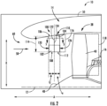
FIG. 2 is a magnified view of a forward end of the exemplary gas turbine engine ofFIG. 1 illustrating a guide vane assembly. -
FIG. 3 is an axial view of an inlet to the exemplary gas turbine engine ofFIG. 1 with a plurality of evenly-spaced guide vane assemblies. -
FIG. 4 is an axial view of an inlet to a gas turbine engine according to another exemplary embodiment with a plurality of unevenly-spaced guide vane assemblies. -
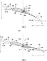
FIG. 5 is a cross-sectional view of the guide vane assembly of the exemplary gas turbine engine ofFIG. 1 along the line 5-5 with an aft vane disposed at a first angle. -
FIG. 6 is a cross-sectional view of the guide vane assembly of the exemplary gas turbine engine ofFIG. 1 with the aft vane disposed at a second angle. -
FIG. 7 is a magnified view of the exemplary gas turbine engine ofFIG. 1 illustrating a variable pitch mechanism. - Reference will now be made in detail to present embodiments of the disclosure, one or more examples of which are illustrated in the accompanying drawings. The detailed description uses numerical and letter designations to refer to features in the drawings. Like or similar designations in the drawings and description have been used to refer to like or similar parts of the disclosure.
- The word "exemplary" is used herein to mean "serving as an example, instance, or illustration." Any implementation described herein as "exemplary" is not necessarily to be construed as preferred or advantageous over other implementations. Additionally, unless specifically identified otherwise, all embodiments described herein should be considered exemplary.
- For the purposes of the description, the terms "upper," "lower," "right," "left," "vertical," "horizontal," "top," "bottom," "lateral," "longitudinal," and derivatives thereof shall relate to the disclosure as oriented in the drawings.
- As may be used herein, the terms "first," "second," "third," and other ordinals are used to distinguish one component from another and are not intended to signify location or importance of the individual components.
- The terms "forward" and "aft" refer to relative positions within a gas turbine engine, with "forward" referring to a position closer to an engine inlet and "aft" referring to a position closer to an engine nozzle or exhaust.
- The terms "upstream" and "downstream" refer to the relative direction with respect to fluid flow in a fluid pathway. For example, "upstream" refers to the direction from which fluid flows, and "downstream" refers to the direction to which the fluid flows.
- The term "attached" refers to two components that are in direct connection with each other. The term "integrated" means either two components that are formed simultaneously as a single piece or two components that are formed separately and then later fixed to each other. The term "unitary structure" means a single piece structure formed monolithically such that components of the unitary structure are formed simultaneously.
- The singular forms "a", "an", and "the" include plural references unless the context clearly dictates otherwise.
- The term "at least one of" in the context of, e.g., "at least one of A, B, and C" refers to only A, only B, only C, or any combination of A, B, and C.
- The phrases "from X to Y" and "between X and Y" each refers to a range of values inclusive of the endpoints (i.e., refers to a range of values that includes both X and Y).
- The present disclosure is generally related to an inlet pre-swirl feature configured as a plurality of guide vane assemblies for an inlet of a gas turbine engine and a control system in communication with components of the gas turbine engine.
- The guide vane assemblies each include a forward vane and an aft vane. The forward vane is positioned at a fixed angle relative to a longitudinal axis of the gas turbine engine. The aft fan is movable between a range of angles relative to the longitudinal axis of the gas turbine engine. In other words, an angle of the aft vane can be varied during operation of the gas turbine engine.
- The angle of the forward vane is fixed to provide rigidity for, e.g., deflecting incoming debris. The angle of the aft vane is variable in order to match the swirl imparted to an incoming air to the airspeed of the aircraft and the rotational speed of the fan such that the angular velocity of the air as it approaches the fan blade corresponds in a desired manner with the angular velocity of the fan blade. The aft vane is configured to pre-swirl the airflow provided through an inlet of the outer nacelle, upstream of the plurality of fan blades of the fan. As discussed herein, pre-swirling the airflow provided through the inlet of the outer nacelle prior to such airflow reaching the plurality of fan blades of the fan may reduce separation losses and/or shock losses, allowing the fan to operate with relatively high fan tip speeds with less losses in efficiency. Having fixed and variable portions of the guide vane assembly allows for rigid protection against incoming debris and pre-swirling of incoming air, improving operation of the gas turbine engine.
- Referring now to the drawings, wherein identical numerals indicate the same elements throughout the figures,
FIG. 1 is a cross-sectional view of a gas turbine engine in accordance with an exemplary embodiment of the present disclosure. More particularly, for the embodiment ofFIG. 1 , the gas turbine engine is an aeronautical,turbofan jet engine 10, referred to herein as "turbofan engine 10." Theturbofan engine 10 is configured to be mounted to an aircraft, such as in an under-wing configuration or a tail-mounted configuration. As shown inFIG. 1 , theturbofan engine 10 defines an axial direction A (extending parallel to a longitudinal centerline provided for reference), a radial direction R, and a circumferential direction (i.e., a direction extending about the axial direction A). The longitudinal centerline defines alongitudinal axis 12 of theturbofan engine 10. In general, theturbofan engine 10 includes afan section 14 and aturbomachine 16 disposed downstream from the fan section 14 (theturbomachine 16 sometimes also, or alternatively, referred to as a "core turbine engine"). - The
exemplary turbomachine 16 depicted generally includes a substantially tubularouter casing 18 that defines anannular inlet 20. Theouter casing 18 encases, in serial flow relationship, a compressor section including a first, booster or low pressure (LP)compressor 22 and a second, high pressure (HP)compressor 24; acombustion section 26; a turbine section including a first, high pressure (HP)turbine 28 and a second, low pressure (LP)turbine 30; and a jetexhaust nozzle section 32. A high pressure (HP) shaft drivingly connects the HPturbine 28 to the HPcompressor 24. A low pressure (LP)shaft 36 drivingly connects theLP turbine 30 to theLP compressor 22. The compressor section,combustion section 26, turbine section, and jetexhaust nozzle section 32 are arranged in serial flow order and together define acore air flowpath 37 through theturbomachine 16. It is also contemplated that the present disclosure is compatible with an engine having an intermediate pressure turbine, e.g., an engine having three spools. - Referring still to the embodiment of
FIG. 1 , thefan section 14 includes a variable pitch,single stage fan 38, theturbomachine 16 operably coupled to thefan 38 for driving thefan 38. Thefan 38 includes a plurality ofrotatable fan blades 40 coupled to adisk 42 in a spaced apart manner. As depicted, thefan blades 40 extend outwardly fromdisk 42 generally along the radial direction R. Eachfan blade 40 is rotatable relative to thedisk 42 about a pitch axis P by virtue of thefan blades 40 being operatively coupled to asuitable actuation member 44 configured to collectively vary the pitch of thefan blades 40, e.g., in unison. Thefan blades 40,disk 42, andactuation member 44 are together rotatable about thelongitudinal centerline 12 by theLP shaft 36 across apower gear box 46. Thepower gear box 46 includes a plurality of gears for stepping down the rotational speed of theLP shaft 36 to a more efficient rotational fan speed. Accordingly, for the embodiment depicted, theturbomachine 16 is operably coupled to thefan 38 through thepower gear box 46. - In exemplary embodiments, the
fan section 14 includes twenty-two (22) orfewer fan blades 40. In other exemplary embodiments, thefan section 14 includes a different number offan blades 40, such as twenty (20), eighteen (18), sixteen (16), or other numbers offan blades 40. - Referring still to the exemplary embodiment of
FIG. 1 , thedisk 42 is covered by a rotatable front nacelle orhub 48 aerodynamically contoured to promote an airflow through the plurality offan blades 40. Additionally, theexemplary fan section 14 includes an annular fan casing orouter nacelle 50 that at least partially (and for the embodiment depicted, circumferentially) surrounds thefan 38 and at least a portion of theturbomachine 16. - More specifically, the
outer nacelle 50 includes aninner wall 52 and adownstream section 54 of theinner wall 52 of theouter nacelle 50 extends over an outer portion of theturbomachine 16 so as to define abypass airflow passage 56 therebetween. Additionally, for the embodiment depicted, theouter nacelle 50 is supported relative to theturbomachine 16 by a plurality of circumferentially spaced outlet guide vanes 55. Theouter nacelle 50 includes aninlet 60 at aleading edge 61 of theouter nacelle 50. - During operation of the
turbofan engine 10, a volume ofair 58 enters theturbofan engine 10 through theinlet 60 of theouter nacelle 50 and/or thefan section 14. As the volume ofair 58 passes cross thefan blades 40, a first portion of theair 58 as indicated byarrow 62 is directed or routed into thebypass airflow passage 56, and a second portion of theair 58 as indicated byarrow 64 is directed or routed into thecore air flowpath 37. The pressure of the second portion of air indicated by thearrow 64 is then increased as it is routed through theHP compressor 24 and into thecombustion section 26, where it is mixed with fuel and burned to providecombustion gases 66. Thecombustion gases 66 are routed from thecombustion section 26 through theHP turbine 28. In theHP turbine 28, a portion of thermal and/or kinetic energy from thecombustion gases 66 is extracted via sequential stages of HPturbine stator vanes 68 that are coupled to theouter casing 18 and HPturbine rotor blades 70 that are coupled to a high pressure (HP)shaft 34, thus causing theHP shaft 34 to rotate, thereby supporting operation of theHP compressor 24. Thecombustion gases 66 are then routed through theLP turbine 30 where a second portion of thermal and/or kinetic energy is extracted from thecombustion gases 66 via sequential stages of LPturbine stator vanes 72 that are coupled to theouter casing 18 and LPturbine rotor blades 74 that are coupled to theLP shaft 36, thus causing theLP shaft 36 to rotate, thereby supporting operation of theLP compressor 22 and/or rotation of thefan 38. - The
combustion gases 66 are subsequently routed through the jetexhaust nozzle section 32 of theturbomachine 16 to provide propulsive thrust. Simultaneously, the pressure of the first portion ofair 62 is substantially increased as the first portion ofair 62 is routed through thebypass airflow passage 56 before it is exhausted from a fannozzle exhaust section 76 of theturbofan engine 10, also providing propulsive thrust. TheHP turbine 28, theLP turbine 30, and the jetexhaust nozzle section 32 at least partially define ahot gas path 78 for routing thecombustion gases 66 through theturbomachine 16. - Referring still to
FIG. 1 , theturbofan engine 10 of the present disclosure also provides pre-swirling flow forward of a tip of thefan blade 40 as described herein. For example, theturbofan engine 10 additional includes one or more inletguide vane assemblies 100, as described in greater detail below. - In some exemplary embodiments, the
exemplary turbofan engine 10 of the present disclosure may be a relatively large powerclass turbofan engine 10. Accordingly, when operated at the rated speed, theturbofan engine 10 may be configured to generate a relatively large amount of thrust. More specifically, when operated at the rated speed, theturbofan engine 10 may be configured to generate at least 20,000 pounds of thrust, such as at least about 25,000, 30,000, and up to, e.g., 150,000 pounds of thrust. Accordingly, theturbofan engine 10 may be referred to as a relatively large power class gas turbine engine. - Moreover, the
exemplary turbofan engine 10 depicted inFIG. 1 is by way of example only, and that in other exemplary embodiments, theturbofan engine 10 may have any other suitable configuration. For example, in certain exemplary embodiments, the fan may not be a variable pitch fan, the engine may not include a reduction gearbox (e.g., the power gearbox 46) driving the fan, and may include any other suitable number or arrangement of shafts, spools, compressors, turbines, etc. - Referring now also to
FIG. 2 , a magnified view of thefan section 14 and forward end of theturbomachine 16 is provided. Aguide vane assembly 100 is located forward of the plurality offan blades 40 in the axial direction A, i.e., upstream of thefan blades 40. Theguide vane assembly 100 may be attached to or integrated into theouter nacelle 50, e.g., formed separately and later attached to each other or formed simultaneously as a unitary structure. - The
guide vane assembly 100 includes aforward vane 102 and anaft vane 104. Theforward vane 102 provides rigidity and debris protection to theguide vane assembly 100. Specifically, theforward vane 102 is configured to deflect objects and other debris entering thenacelle 50, and theforward vane 102 may be formed of a material with specified stiffness or modulus in order to deflect the objects while inhibiting deformation. The material of theforward vane 102 may have a higher stiffness or modulus than a material of theaft vane 104. For example, theforward vane 102 may be metal, such as steel or titanium, and theaft vane 104 may be a composite, such as a carbon fiber polymer. As another example, both theforward vane 102 and theaft vane 104 may be metals, or both may be composites, where the stiffness or modulus of theforward vane 102 is greater than the stiffness or modulus of theaft vane 104. When theguide vane assembly 100 is positioned in thenacelle 50, theforward vane 102 may be attached to or integrated with thenacelle 50. - The
aft vane 104 provides a swirl control feature to control swirl ofair 58 flowing past theguide vane assembly 100 toward thefan blades 40. Specifically, as will be explained in greater detail below, theaft vane 104 is movable relative to theforward vane 102 in order to control air flow to thefan blades 40. Theaft vane 104 is located aft of theforward vane 102 and forward of thefan blades 40. When theguide vane assembly 100 is positioned in thenacelle 50, at least a portion of theaft vane 104 is attached to or integrated with thenacelle 50. That is, while theaft vane 104 is generally movable relative to theforward vane 102, a portion of theaft vane 104 may be attached to or integrated with thenacelle 50 to secure theaft vane 104 in place. This fixed portion may be, e.g., a rod around which a movable portion of theaft vane 104 rotates (as shown inFIGS. 5-6 and described below), and the fixed portion may extend into thenacelle 50 to a suitable attachment point or may be integrated into thenacelle 50. - The
forward vane 102 extends generally along the radial direction R from anouter end 106 to aninner end 108, and theaft vane 104 extends generally along the radial direction R from anouter end 110 to aninner end 112. A "span" of theforward vane 102 or theaft vane 104 is a length in the radial direction R from theouter end inner end forward vane 102 is a "forward vane span" 114, and the span of the aft vane is an "aft vane span" 116. The inner ends 108, 112 of theforward vane 102 and theaft vane 104 extend freely and do not include any intermediate connection members at the inner ends 108, 112, such as a connection ring, strut, or the like. More specifically, theforward vane 102 and theaft vane 104 are completely supported by a connection to thenacelle 50 at the outer ends 106, 110 and not through any structure extending, e.g., between adjacentguide vane assemblies 100. In this exemplary embodiment, theforward vane span 114 is less than theaft vane span 116, and it is appreciated that the larger of theforward vane span 114 and theaft vane span 116 can define a total span of theguide vane assembly 100, i.e., a "guide vane assembly span." - As will be appreciated, the plurality of
fan blades 40 each define afan blade span 118. In this exemplary embodiment, theforward vane span 114 and the aft vane span 116 (and thus the guide vane assembly span) are from 5% to 50% of the fan blade span, e.g., from 5% to 10%. In general, the guide vane assembly span may be expressed as a percentage of thefan blade span 118. - The
forward vane 102 extends generally along the axial direction A from aleading edge 120 to a trailingedge 122, defining a "forward axial length," and theaft vane 104 extends generally along the axial direction A from aleading edge 124 to a trailingedge 126, defining an "aft axial length." - More specifically, the trailing
edge 122 of theforward vane 102 abuts theleading edge 124 of theaft vane 104. Alternatively, the trailingedge 122 of theforward vane 102 may be spaced or separated from theleading edge 124 of theaft vane 104, defining a gap therebetween. In this embodiment, at a specific radial position within thenacelle 50, theforward vane 104 defines a forward axial length Lf between theleading edge 120 and the trailingedge 122, and theaft vane 104 defines an aft axial length La between theleading edge 124 and the trailingedge 126. In the exemplary embodiment depicted, the forward axial length Lf and aft axial length La are each measured at a common position along the radial direction R and are measured in the axial direction A. In particular, for the embodiment depicted, the forward axial length Lf and aft axial length La are each measured at a location along the radial direction R corresponding to a 50% span of theforward vane 102. - As part of the design of the
guide vane assembly 100 of the present disclosure, the inventors of the present disclosure designed several iterations that would satisfy the design requirements identified. In particular, the inventors of the present disclosure designed several iterations that would be of a sufficient stiffness to withstand contact with debris, while having sufficient variability to provide desired aerodynamics benefits at various flight conditions. These iterations included inlet guide vanes of various spans relative to the fan blades. As part of these design iterations, the inventors of the present disclosure found a significant relationship between the forward axial length Lf and aft axial length La to meet these design requirements. - In particular, the inventors of the present disclosure found that as the guide vane assembly span increases, more debris contacts the
forward vane 102 during flight operation and an increased forward axial length Lf is generally required to inhibit damage to theforward vane 102. Such a configuration thereby increasing an overall stiffness of theguide vane assembly 100. As a result, the aft axial length La may be decreased to maintain a constant axial length of theguide vane assembly 100, as shown in Table 1. That is, the aft axial length La may be inversely related to the forward axial length Lf as the guide vane assembly span increases. - In this exemplary embodiment, a ratio of the aft axial length La to the forward axial length Lf is from 0.2 to 5.0. More specifically, the
guide vane assembly 100 is designed such that, based on the guide vane assembly span, the forward axial length Lf and the aft axial length La are determined such that theforward vane 102 provides debris protection while theaft vane 104 provides swirl control. Table 1 below shows example forward axial lengths Lf and aft axial lengths La for exampleguide vane assemblies 100 having specified guide vane assembly spans. Table 1 also shows a minimum aft axial length (i.e., 0.2Lf ) of theaft vane 104 and a maximum aft axial length (i.e., 5.0Lf ) of theaft vane 104 for this exemplary embodiment.Table 1: Axial Lengths of Forward and Aft Vanes Guide Vane Assembly Span (% of fan blade span) Forward Axial Length (inches) Aft Axial Length (inches) 0.2Lf 5.0Lf 5 1.00 4.00 0.20 5.00 10 1.33 3.67 0.27 6.67 15 1.67 3.33 0.33 8.33 20 2.00 3.00 0.40 10.00 25 2.33 2.67 0.41 11.67 30 2.67 2.33 0.53 13.33 35 3.00 2.00 0.60 15.00 40 3.33 1.67 0.67 16.67 45 3.67 1.33 0.73 18.33 50 4.00 1.00 0.80 20.00 - As shown in
FIG. 3 , an axial view of theinlet 60 of theturbofan engine 10 is shown. In this embodiment, the plurality ofguide vane assemblies 100 includes a relatively large number ofguide vane assemblies 100 arranged circumferentially around thenacelle 50. More specifically, the plurality ofguide vane assemblies 100 shown inFIG. 3 is from about tenguide vane assemblies 100 to about fiftyguide vane assemblies 100. The plurality ofguide vane assemblies 100 are arranged substantially evenly along a circumferential direction C. More specifically, each of the plurality ofguide vane assemblies 100 defines acircumferential spacing 128 with an adjacentguide vane assembly 100, and each of thecircumferential spacings 128 are substantially equal to each other of thecircumferential spacings 128. - Alternatively, as shown in
FIG. 4 , thecircumferential spacings 128 between theguide vane assemblies 100 may differ. That is, at least one of thecircumferential spacings 128 may differ from at least one of the othercircumferential spacings 128. For example, a firstcircumferential spacing 128A defined between two adjacentguide vane assemblies guide vane assemblies 100B, 100C. In this example, the firstcircumferential spacing 128A is at least about twenty percent greater than the second circumferential spacing 128B, such as at least about twenty-five percent greater and up to about two hundred percent greater. The non-uniformcircumferential spacings 128 may, e.g., offset structure upstream of theguide vane assemblies 100. - Now referring to
FIGS. 5-6 , a cross-sectional view of a part span inlet guide vane of theguide vane assembly 100 ofFIG. 2 is shown. As depicted, theguide vane assembly 100 is configured generally as an airfoil having apressure side 130 and asuction side 132 and extending from theleading edge 120 of theforward vane 102 to the trailingedge 126 of theaft vane 104. For this exemplary embodiment, a direction ofairflow 58 is substantially parallel to the axial direction A and thelongitudinal axis 12 of theturbofan engine 10. - The forward and
aft vanes longitudinal axis 12 of the turbofan engine 10 (FIG. 2 ), represented as thelongitudinal centerline 12, and a chord extending from theleading edge edge forward vane 102 or theaft vane 104. More specifically, achord 138 for theforward vane 104 is defined between a forwardmost point of theforward vane 102 and the aftmost point of theforward vane 102, and achord 140 for theaft vane 104 is defined between a forwardmost point of theaft vane 104 and an aftmost point of theaft vane 104. Thepitch angle 134 of theforward vane 102 is fixed so that the rigidity of theforward vane 102 is increased, improving debris deflection of theforward vane 102. That is, by fixing thepitch angle 134 of theforward vane 102, theforward vane 102 may be fixed to thenacelle 50 more rigidly, increasing the stiffness of theforward vane 102. - The pitch angle 136 of the
aft vane 104 is movable to provide controlled swirl ofairflow 58 past theguide vane assembly 100. As described above, theaft vane 104 may include a fixedportion 104A such as a rod attached to or integrated with thenacelle 50 about which amovable portion 104B of theaft vane 104 rotates. Themovable portion 104B is rotatable about a pitch axis P extending through the fixedportion 104A such that theaft vane 104 is movable between a first pitch angle 136A, such as the pitch angle 136 shown inFIG. 5 , and a second pitch angle 136B, such as the pitch angle 136 shown inFIG. 6 . By moving theaft vane 104 between different pitch angles 136, theaft vane 104 controls swirl ofairflow 58 past theguide vane assembly 100, which may reduce turbulence of theairflow 58 and/or provide a specified amount of pre-swirl at the radially outward ends of thefan blades 40, where the speed of the fan blades 40 (FIG. 2 ) is greatest, to provide a desired reduction in flow separation and/or shock losses that may otherwise occur due to a relatively high speed of the plurality offan blades 40 at the fan tips during operation of theturbofan engine 10. In the exemplary embodiment ofFIGS. 5-6 , theaft vane 104 is movable between a minimum pitch angle of 5 degrees to a maximum pitch angle of 35 degrees. - The specific pitch angle 136 of the
aft vane 104 may be determined to match the swirl imparted to theincoming airflow 58 to the airspeed of the aircraft and the rotational speed of the fan 38 (FIG. 2 ) such that the angular velocity of the air as it approaches thefan blade 40 corresponds as closely as possible with the angular velocity of thefan blade 40. This minimizes the potential of thefan 38 to surge or stall. The faster thefan 38 rotates, the more swirl that needs to be imparted by theguide vane assemblies 100. As the airspeed of the aircraft increases, the time that it takes for the incoming air to pass from theguide vane assemblies 100 to the leading edge of thefan 38 decreases, and as such the necessary amount of swirl decreases proportionately. As such the maximum imparted swirl is required when theturbofan engine 10 is at maximum thrust with a stationary aircraft, just prior to beginning a takeoff roll. - Now referring to
FIG. 7 , a magnified view of theturbofan engine 10 is shown. Theturbofan engine 10 may include avariable pitch mechanism 142 that is operably coupled to theaft vane 104. Thevariable pitch mechanism 142 is configured to move theaft vane 104 about the pitch axis P to a specified pitch angle 136, e.g., from the first angle 136A to the second angle 136B shown inFIGS. 5-6 . It is contemplated that thevariable pitch mechanism 142 may include, for example, a stepper motor, a torque motor, or a similar drive component. Acontroller 144 communicates with and actuates thevariable pitch mechanism 142 to move theaft vane 104. Thecontroller 144 includes a processor and a memory, and the processor is configured to determine when to change the pitch angle 136 of theaft vane 104 based on data from one or more sensors (not shown), such as crosswind sensors, pressure sensors, blade passing sensors, temperature sensors, or the like. The processor then actuates thevariable pitch mechanism 142 to move theaft vane 104 to a specified pitch angle 136. - Further aspects are provided by the subject matter of the following clauses:
A guide vane assembly for a nacelle of a gas turbine engine, the gas turbine engine defining a longitudinal axis and an axial direction, the nacelle circumferentially surrounding a plurality of fan blades of the gas turbine engine, includes a forward vane and an aft vane located aft of the forward vane and forward of the plurality of fan blades when the guide vane assembly is positioned in the nacelle of the gas turbine engine, the forward vane defining a fixed pitch angle and the aft vane being movable between a first angle with respect to the longitudinal axis and a second angle with respect to the longitudinal axis when the guide vane assembly is positioned in the nacelle of the gas turbine engine. - A guide vane assembly for a nacelle of a gas turbine engine, the gas turbine engine defining a longitudinal axis and an axial direction, the nacelle circumferentially surrounding a plurality of fan blades of the gas turbine engine, the guide vane assembly comprising; a forward vane; and an aft vane located aft of the forward vane and forward of the plurality of fan blades when the guide vane assembly is positioned in the nacelle of the gas turbine engine, the forward vane defining a fixed pitch angle and the aft vane being movable between a first pitch angle and a second pitch angle when the guide vane assembly is positioned in the nacelle of the gas turbine engine.
- The guide vane assembly of any of the preceding clauses, wherein the forward vane defines a forward axial length at a radial position, wherein the aft vane defines an aft axial length at the radial position, wherein a ratio of the aft axial length to the forward axial length is from 0.2 to 5.0.
- The guide vane assembly of any of the preceding clauses, wherein the axial length of the aft vane is based on a span of the forward vane.
- The guide vane assembly of any of the preceding clauses, wherein a trailing edge of the forward vane abuts a leading edge of the aft vane.
- The guide vane assembly of any of the preceding clauses, wherein the forward vane defines a forward vane span, wherein the plurality of fan blades each defines a fan blade span, and wherein the forward vane span is between 5% and 50% of the fan blade span of the plurality of fan blades.
- The guide vane assembly of any of the preceding clauses, wherein the forward vane span of the forward vane is from 5% to 10% of the fan blade span of the plurality of fan blades.
- The guide vane assembly of any of the preceding clauses, wherein the forward vane span is from 5% to 10% of the fan blade span.
- The guide vane assembly of any of the preceding clauses, wherein the forward vane comprises a first material, wherein the aft vane comprises a second material, and wherein the first material has a higher stiffness than the second material.
- The guide vane assembly of any of the preceding clauses, wherein the forward vane is configured to deflect objects entering the nacelle.
- The guide vane assembly of any of the preceding clauses, wherein the forward vane and the aft vane are each attached to or integrated with the nacelle when the guide vane assembly is positioned in the nacelle of the gas turbine engine.
- The guide vane assembly of any of the preceding clauses, wherein the forward vane is fixed to a specified angle with respect to the longitudinal axis of the nacelle when the guide vane assembly is positioned in the nacelle of the gas turbine engine.
- The guide vane assembly of any of the preceding clauses, wherein the forward vane is fixed to a specified pitch angle when the guide vane assembly is positioned in the nacelle of the gas turbine engine.
- The guide vane assembly of any of the preceding clauses, wherein the first and second angles are between 5 degrees and 35 degrees.
- The guide vane assembly of any of the preceding clauses, wherein the first and second pitch angles are from 5 degrees to 35 degrees.
- The guide vane assembly of any of the preceding clauses, further including a variable pitch mechanism operably coupled to the aft vane configured to move the aft vane from the first angle to the second angle.
- The guide vane assembly of any of the preceding clauses, further comprising: a variable pitch mechanism operably coupled to the aft vane and configured to move the aft vane from the first pitch angle to the second pitch angle.
- The guide vane assembly of any of the preceding clauses, wherein a forward vane span of the forward vane is less than an aft vane span of the aft vane.
- A turbofan engine defining a longitudinal axis and an axial direction includes a fan including a plurality of fan blades, a turbomachine operably coupled to the fan and configured to drive the fan, a nacelle surrounding and at least partially enclosing the fan, and a guide vane assembly located forward of the plurality of fan blades in the axial direction, the guide vane assembly including a forward vane and an aft vane located aft of the forward vane and forward of the plurality of fan blades when the guide vane assembly is positioned in the nacelle of the gas turbine engine, the forward vane defining a fixed pitch angle and the aft vane being movable between a first angle with respect to the longitudinal axis and a second angle with respect to the longitudinal axis when the guide vane assembly is positioned in the nacelle of the turbofan engine.
- A turbofan engine defining a longitudinal axis and an axial direction, the turbofan engine comprising: a fan comprising a plurality of fan blades; a turbomachine operably coupled to the fan and configured to drive the fan; a nacelle surrounding and at least partially enclosing the fan; and a guide vane assembly located forward of the plurality of fan blades in the axial direction, the guide vane assembly including a forward vane and an aft vane located aft of the forward vane and forward of the plurality of fan blades when the guide vane assembly is positioned in the nacelle of the gas turbine engine, the forward vane defining a fixed pitch angle and the aft vane being movable between a first pitch angle and a second pitch angle when the guide vane assembly is positioned in the nacelle of the turbofan engine.
- The turbofan engine of any of the preceding clauses, wherein the guide vane assembly is attached to or integrated with the nacelle.
- The turbofan engine of any of the preceding clauses, further including a plurality of guide vane assemblies disposed circumferentially around the nacelle.
- The turbofan engine of any of the preceding clauses, wherein the plurality of guide vane assemblies define a circumferential spacing between each adjacent pair of the plurality of guide vane assemblies.
- The turbofan engine of any of the preceding clauses, wherein the circumferential spacing between each adjacent pair of the plurality of guide vane assemblies is equal.
- The turbofan engine of any of the preceding clauses, wherein the circumferential spacing between at least one adjacent pair of the plurality of guide vane assemblies is different than the circumferential spacing of at least one other adjacent pair of the plurality of guide vane assemblies.
- The turbofan engine of any of the preceding clauses, wherein the circumferential spacing between each adjacent pair of the plurality of guide vane assemblies is different from the circumferential spacing of each other adjacent pair of the plurality of guide vane assemblies.
- The turbofan engine of any of the preceding clauses, wherein the forward vane defines a forward axial length at a radial position, wherein the aft vane defines an aft axial length at the radial position, wherein a ratio of the aft axial length to the forward axial length is from 0.2 to 5.0.
- The turbofan engine of any of the preceding clauses, wherein the aft axial length is based on a span of the forward vane.
- The turbofan engine of any of the preceding clauses, wherein the span of the forward vane is from 5% to 50% of a span of the plurality of fan blades.
- The turbofan engine of any of the preceding clauses, further including a variable pitch mechanism operably coupled to the aft vane configured to move the aft vane from the first angle to the second angle.
- The turbofan engine of any of the preceding clauses, further including a variable pitch mechanism operably coupled to the aft vane configured to move the aft vane from the first pitch angle to the second pitch angle.
- The turbofan engine of any of the preceding clauses, wherein the forward vane comprises a first material, wherein the aft vane comprises a second material, and wherein the first material has a higher stiffness than the second material.
- The turbofan engine of any of the preceding clauses, further including a controller in communication with the variable pitch mechanism and configured to actuate the variable pitch mechanism to move the aft vane.
- The turbofan engine of any of the preceding clauses, wherein the forward vane is fixed to a specified pitch angle when the guide vane assembly is positioned in the nacelle of the turbofan engine.
- This written description uses examples to disclose the present disclosure, including the best mode, and also to enable any person skilled in the art to practice the disclosure, including making and using any devices or systems and performing any incorporated methods. The patentable scope of the disclosure is defined by the claims, and may include other examples that occur to those skilled in the art. Such other examples are intended to be within the scope of the claims if they include structural elements that do not differ from the literal language of the claims, or if they include equivalent structural elements with insubstantial differences from the literal languages of the claims.
Claims (15)
- A guide vane assembly (100) for a nacelle (50) of a gas turbine engine (10), the gas turbine engine (10) defining a longitudinal axis (12) and an axial direction, the nacelle (50) circumferentially surrounding a plurality of fan blades (40) of the gas turbine engine (10), the guide vane assembly (100) comprising:a forward vane (102); andan aft vane (104) located aft of the forward vane (102) and forward of the plurality of fan blades (40) when the guide vane assembly (100) is positioned in the nacelle (50) of the gas turbine engine (10), the forward vane (102) defining a fixed pitch angle (134) and the aft vane (104) being movable between a first pitch angle (136) and a second pitch angle (136) when the guide vane assembly (100) is positioned in the nacelle (50) of the gas turbine engine (10).
- The guide vane assembly (100) of claim 1, wherein the forward vane (102) defines a forward axial length at a radial position, wherein the aft vane (104) defines an aft axial length at the radial position, wherein a ratio of the aft axial length to the forward axial length is from 0.2 to 5.0.
- The guide vane assembly (100) of any of the preceding claims,
wherein the axial length of the aft vane (104) is based on a span of the forward vane. - The guide vane assembly (100) of any of the preceding claims,
wherein a trailing edge (122) of the forward vane (102) abuts a leading edge (124) of the aft vane (104). - The guide vane assembly (100) of any of the preceding claims,
wherein the forward vane (102) defines a forward vane span (114), wherein the plurality of fan blades (40) each defines a fan blade span (118), and wherein the forward vane span (118) is from 5% to 50% of the fan blade span (118) of the plurality of fan blades (40). - The guide vane assembly (100) of any of the preceding claims,
wherein the forward vane span (114) of the forward vane (102) is from 5% to 10% of the fan blade span (118) of the plurality of fan blades (40). - The guide vane assembly (100) of any of the preceding claims,
wherein the forward vane (102) comprises a first material, wherein the aft vane (104) comprises a second material, and wherein the first material has a higher stiffness than the second material. - The guide vane assembly (100) of any of the preceding claims,
wherein the forward vane (102) is configured to deflect objects entering the nacelle (50). - The guide vane assembly (100) of any of the preceding claims,
wherein the forward vane (102) and the aft vane (104) are each attached to or integrated with the nacelle (50) when the guide vane assembly (100) is positioned in the nacelle (50) of the gas turbine engine (10). - The guide vane assembly (100) of any of the preceding claims,
wherein the forward vane (102) is fixed to a specified pitch angle (134) when the guide vane assembly (100) is positioned in the nacelle (50) of the gas turbine engine (10). - The guide vane assembly (100) of any of the preceding claims,
wherein the first and second pitch angles (136) are from 5 degrees to 35 degrees. - The guide vane assembly (100) of any of the preceding claims, further comprising:
a variable pitch mechanism (142) operably coupled to the aft vane (104) configured to move the aft vane (104) from the first pitch angle (136) to the second pitch angle (136). - A gas turbine engine (10) defining a longitudinal axis (12) and an axial direction, the gas turbine engine (10) comprising:a fan (38) comprising the plurality of fan blades (40);a turbomachine (16) operably coupled to the fan (38) and configured to drive the fan (38); anda guide vane assembly (100) according to any of claims 1-12.
- The gas turbine engine (10) of claim 13, further comprising:
a plurality of guide vane assemblies (100) disposed circumferentially around the nacelle (50). - The gas turbine engine (10) of claim 13 or 14, further comprising a controller (144) configured to actuate the variable pitch mechanism (142).
Applications Claiming Priority (1)
| Application Number | Priority Date | Filing Date | Title |
|---|---|---|---|
| US18/527,567 US12228037B1 (en) | 2023-12-04 | 2023-12-04 | Guide vane assembly with fixed and variable pitch inlet guide vanes |
Publications (1)
| Publication Number | Publication Date |
|---|---|
| EP4567258A1 true EP4567258A1 (en) | 2025-06-11 |
Family
ID=93741226
Family Applications (1)
| Application Number | Title | Priority Date | Filing Date |
|---|---|---|---|
| EP24216125.5A Pending EP4567258A1 (en) | 2023-12-04 | 2024-11-28 | Guide vane assembly with fixed and variable pitch inlet guide vanes |
Country Status (3)
| Country | Link |
|---|---|
| US (2) | US12228037B1 (en) |
| EP (1) | EP4567258A1 (en) |
| CN (1) | CN120100535A (en) |
Families Citing this family (1)
| Publication number | Priority date | Publication date | Assignee | Title |
|---|---|---|---|---|
| US12435641B1 (en) * | 2024-04-05 | 2025-10-07 | Rtx Corporation | Tailoring aircraft powerplant split line with inflatable bladder(s) |
Citations (6)
| Publication number | Priority date | Publication date | Assignee | Title |
|---|---|---|---|---|
| EP1111191B1 (en) * | 1999-12-18 | 2006-03-22 | General Electric Company | Stator with particular circumferential spacing of the airfoils |
| EP1340894B1 (en) * | 2002-02-28 | 2007-06-13 | General Electric Company | Variable inlet guide vanes for varying gas turbine engine inlet air flow |
| EP1566522B1 (en) * | 2004-02-12 | 2008-11-12 | Snecma | Double fan turbofan engine having variable fan guide vanes |
| US9249736B2 (en) * | 2008-12-29 | 2016-02-02 | United Technologies Corporation | Inlet guide vanes and gas turbine engine systems involving such vanes |
| US9879561B2 (en) * | 2012-08-09 | 2018-01-30 | Snecma | Turbomachine comprising a plurality of fixed radial blades mounted upstream of the fan |
| EP3670849A1 (en) * | 2018-12-17 | 2020-06-24 | United Technologies Corporation | Variable vane assemblies configured for non-axisymmetric actuation |
Family Cites Families (245)
| Publication number | Priority date | Publication date | Assignee | Title |
|---|---|---|---|---|
| US2663993A (en) | 1945-10-10 | 1953-12-29 | Westinghouse Electric Corp | Deicing apparatus |
| US2634581A (en) | 1947-08-27 | 1953-04-14 | Rolls Royce | Separate burner system for deicing the inlets of multiple gas turbine units |
| FR1038694A (en) | 1950-05-17 | 1953-09-30 | Rolls Royce | Improvements to gas turbine power generators incorporating defrosters |
| US3540682A (en) | 1964-12-02 | 1970-11-17 | Gen Electric | Turbofan type engine frame and support system |
| US3533486A (en) | 1968-11-08 | 1970-10-13 | Gen Electric | Jet engine silencer with retractable sound absorbing body |
| US3618876A (en) | 1969-12-22 | 1971-11-09 | Boeing Co | Aircraft engine leading edge auxiliary air inlet |
| US3664612A (en) | 1969-12-22 | 1972-05-23 | Boeing Co | Aircraft engine variable highlight inlet |
| US3575259A (en) | 1970-04-10 | 1971-04-20 | Boeing Co | Retractable noise suppression system |
| US3762835A (en) * | 1971-07-02 | 1973-10-02 | Gen Electric | Foreign object damage protection for compressor blades and other structures and related methods |
| US3819008A (en) | 1972-10-19 | 1974-06-25 | Gen Electric | Broad band acoustic barrier |
| US3861822A (en) | 1974-02-27 | 1975-01-21 | Gen Electric | Duct with vanes having selectively variable pitch |
| US3981466A (en) | 1974-12-23 | 1976-09-21 | The Boeing Company | Integrated thermal anti-icing and environmental control system |
| US4254619A (en) | 1978-05-01 | 1981-03-10 | General Electric Company | Partial span inlet guide vane for cross-connected engines |
| US4688745A (en) | 1986-01-24 | 1987-08-25 | Rohr Industries, Inc. | Swirl anti-ice system |
| US5010729A (en) | 1989-01-03 | 1991-04-30 | General Electric Company | Geared counterrotating turbine/fan propulsion system |
| US4993918A (en) * | 1989-05-19 | 1991-02-19 | United Technologies Corporation | Replaceable fairing for a turbine exhaust case |
| JPH04132899A (en) * | 1990-09-25 | 1992-05-07 | Mitsubishi Heavy Ind Ltd | Axial blower |
| KR100305434B1 (en) | 1991-10-04 | 2001-12-28 | 마에다 시게루 | Turbomachinery |
| US5794432A (en) * | 1996-08-27 | 1998-08-18 | Diversitech, Inc. | Variable pressure and variable air flow turbofan engines |
| US5952621A (en) * | 1997-04-16 | 1999-09-14 | Gte Internetworking Incorporated | Sound attenuation system and related method |
| ATE226689T1 (en) | 1998-07-22 | 2002-11-15 | Friedmund Nagel | DEVICE AND METHOD FOR ACTIVELY REDUCING THE SOUND EMISSIONS OF JET ENGINES AND FOR THE DIAGNOSIS THEREOF |
| CA2293076C (en) * | 1999-12-22 | 2010-03-30 | Man-Chun Tse | Fan and compressor noise attenuation |
| US6585482B1 (en) | 2000-06-20 | 2003-07-01 | General Electric Co. | Methods and apparatus for delivering cooling air within gas turbines |
| FR2814197B1 (en) | 2000-09-21 | 2003-01-10 | Snecma Moteurs | METHOD AND DEVICE FOR MITIGATION OF ROTOR / STATOR INTERACTION SOUNDS IN A TURBOMACHINE |
| US6409469B1 (en) | 2000-11-21 | 2002-06-25 | Pratt & Whitney Canada Corp. | Fan-stator interaction tone reduction |
| US6431820B1 (en) | 2001-02-28 | 2002-08-13 | General Electric Company | Methods and apparatus for cooling gas turbine engine blade tips |
| US6457938B1 (en) | 2001-03-30 | 2002-10-01 | General Electric Company | Wide angle guide vane |
| US6508630B2 (en) | 2001-03-30 | 2003-01-21 | General Electric Company | Twisted stator vane |
| US6540477B2 (en) | 2001-05-21 | 2003-04-01 | General Electric Company | Turbine cooling circuit |
| DE10390754D2 (en) | 2002-02-28 | 2005-05-12 | Mtu Aero Engines Gmbh | Recirculation structure for turbocompressors |
| AU2003207365A1 (en) | 2002-02-28 | 2003-09-09 | Daimlerchrysler Ag | Anti-stall tip treatment means for turbo-compressors |
| US6655632B1 (en) | 2002-08-27 | 2003-12-02 | General Electric Company | System and method for actively changing an effective flow-through area of an inlet region of an aircraft engine |
| US6834505B2 (en) | 2002-10-07 | 2004-12-28 | General Electric Company | Hybrid swirler |
| US6792758B2 (en) * | 2002-11-07 | 2004-09-21 | Siemens Westinghouse Power Corporation | Variable exhaust struts shields |
| GB0316257D0 (en) | 2003-07-11 | 2003-08-13 | Rolls Royce Plc | Compressor with an electrically heated variable inlet guide vane |
| FR2857699B1 (en) | 2003-07-17 | 2007-06-29 | Snecma Moteurs | DEFROSTING DEVICE FOR TURBOMACHINE INPUT DIRECTION WHEEL DARK, DAWN WITH SUCH A DEFROSTING DEVICE, AND AIRCRAFT ENGINE EQUIPPED WITH SUCH AUBES |
| US7096657B2 (en) | 2003-12-30 | 2006-08-29 | Honeywell International, Inc. | Gas turbine engine electromechanical variable inlet guide vane actuation system |
| US7025565B2 (en) | 2004-01-14 | 2006-04-11 | General Electric Company | Gas turbine engine component having bypass circuit |
| US7246773B2 (en) | 2004-05-06 | 2007-07-24 | Goodrich Coporation | Low power, pulsed, electro-thermal ice protection system |
| US8021104B2 (en) | 2004-06-07 | 2011-09-20 | Honeywell International Inc. | Compressor apparatus with recirculation and method therefore |
| US8757959B2 (en) | 2004-12-01 | 2014-06-24 | United Technologies Corporation | Tip turbine engine comprising a nonrotable compartment |
| US8641367B2 (en) | 2004-12-01 | 2014-02-04 | United Technologies Corporation | Plurality of individually controlled inlet guide vanes in a turbofan engine and corresponding controlling method |
| WO2006060000A1 (en) | 2004-12-01 | 2006-06-08 | United Technologies Corporation | Variable fan inlet guide vane assembly, turbine engine with such an assembly and corresponding controlling method |
| EP1674694B1 (en) | 2004-12-23 | 2014-02-12 | Rolls-Royce plc | Compressor intake duct |
| US7407364B2 (en) | 2005-03-01 | 2008-08-05 | Honeywell International, Inc. | Turbocharger compressor having ported second-stage shroud, and associated method |
| US7374403B2 (en) | 2005-04-07 | 2008-05-20 | General Electric Company | Low solidity turbofan |
| US7520715B2 (en) | 2005-07-19 | 2009-04-21 | Pratt & Whitney Canada Corp. | Turbine shroud segment transpiration cooling with individual cast inlet and outlet cavities |
| US7374404B2 (en) | 2005-09-22 | 2008-05-20 | General Electric Company | Methods and apparatus for gas turbine engines |
| FR2891313A1 (en) | 2005-09-26 | 2007-03-30 | Airbus France Sas | DOUBLE FLOW TURBOMOTEUR HAVING A PRE-COOLER |
| US7413401B2 (en) | 2006-01-17 | 2008-08-19 | General Electric Company | Methods and apparatus for controlling variable stator vanes |
| US20070187381A1 (en) | 2006-02-16 | 2007-08-16 | United Technologies Corporation | Heater assembly for deicing and/or anti-icing a component |
| US7435056B2 (en) * | 2006-02-28 | 2008-10-14 | Honeywell International Inc. | Leading edge erosion protection for composite stator vanes |
| US7313963B2 (en) | 2006-02-28 | 2008-01-01 | General Electric Company | Isothermal de-iced sensor |
| FR2902758B1 (en) | 2006-06-21 | 2009-04-10 | Airbus France Sas | PROPELLANT AIRCRAFT ASSEMBLY COMPRISING AN EJECTION DUCT WITH A LEAK EDGE OFFSET |
| US20080041064A1 (en) | 2006-08-17 | 2008-02-21 | United Technologies Corporation | Preswirl pollution air handling with tangential on-board injector for turbine rotor cooling |
| EP3128164B1 (en) | 2006-08-22 | 2019-07-10 | Rolls-Royce North American Technologies, Inc. | Gas turbine engine with intermediate speed booster |
| EP2066872B1 (en) | 2006-10-12 | 2014-06-18 | United Technologies Corporation | Method and device to avoid turbofan instability in a gas turbine engine. |
| US20080155959A1 (en) | 2006-12-22 | 2008-07-03 | General Electric Company | Detonation combustor to turbine transition piece for hybrid engine |
| US7811050B2 (en) | 2006-12-28 | 2010-10-12 | General Electric Company | Operating line control of a compression system with flow recirculation |
| US7871244B2 (en) | 2007-02-15 | 2011-01-18 | Siemens Energy, Inc. | Ring seal for a turbine engine |
| FR2915522A1 (en) | 2007-04-30 | 2008-10-31 | Airbus France Sas | Acoustic attenuation panel i.e. acoustic attenuation lining, for propulsion system of aircraft, has cellular structure whose one of characteristics varies acoustic wave to locally oppose acoustic wave to impedance variations |
| US7874137B2 (en) | 2007-06-18 | 2011-01-25 | Honeywell International Inc. | Gas turbine engine anti-ice formation device and system |
| US7942632B2 (en) | 2007-06-20 | 2011-05-17 | United Technologies Corporation | Variable-shape variable-stagger inlet guide vane flap |
| US9957918B2 (en) | 2007-08-28 | 2018-05-01 | United Technologies Corporation | Gas turbine engine front architecture |
| US7955046B2 (en) | 2007-09-25 | 2011-06-07 | United Technologies Corporation | Gas turbine engine front architecture modularity |
| US8186942B2 (en) | 2007-12-14 | 2012-05-29 | United Technologies Corporation | Nacelle assembly with turbulators |
| GB2457427A (en) | 2007-12-14 | 2009-08-19 | Rolls Royce Plc | Gas turbine engine cooling flow modulation arrangement comprising fluidic valves |
| US8529188B2 (en) | 2007-12-17 | 2013-09-10 | United Technologies Corporation | Fan nacelle flow control |
| FR2925878B1 (en) | 2007-12-28 | 2010-04-23 | Airbus France | PROPELLANT AIRCRAFT ASSEMBLY COMPRISING HOT AIR COLLECTION SYSTEMS |
| US8393062B2 (en) * | 2008-03-31 | 2013-03-12 | United Technologies Corp. | Systems and methods for positioning fairing sheaths of gas turbine engines |
| US8061142B2 (en) | 2008-04-11 | 2011-11-22 | General Electric Company | Mixer for a combustor |
| US8806871B2 (en) | 2008-04-11 | 2014-08-19 | General Electric Company | Fuel nozzle |
| US8245981B2 (en) | 2008-04-30 | 2012-08-21 | General Electric Company | Ice shed reduction for leading edge structures |
| US8226360B2 (en) | 2008-10-31 | 2012-07-24 | General Electric Company | Crenelated turbine nozzle |
| US20100226783A1 (en) * | 2009-03-06 | 2010-09-09 | General Electric Company | Erosion and Corrosion Resistant Turbine Compressor Airfoil and Method of Making the Same |
| US8105042B2 (en) | 2009-04-06 | 2012-01-31 | United Technologies Corporation | Intermediate-manufactured composite airfoil and methods for manufacturing |
| US8328518B2 (en) | 2009-08-13 | 2012-12-11 | Siemens Energy, Inc. | Turbine vane for a gas turbine engine having serpentine cooling channels |
| US8419374B2 (en) | 2009-08-14 | 2013-04-16 | Hamilton Sundstrand Corporation | Gas turbine engine composite blade |
| GB0914591D0 (en) | 2009-08-21 | 2009-09-30 | Rolls Royce Plc | Fluidfoil tip vortex disruption |
| US8689538B2 (en) | 2009-09-09 | 2014-04-08 | The Boeing Company | Ultra-efficient propulsor with an augmentor fan circumscribing a turbofan |
| CN101922312B (en) | 2010-03-24 | 2013-11-06 | 北京航空航天大学 | Method for controlling radial clearance leakage loss of turbomachine |
| US9114877B2 (en) | 2010-08-30 | 2015-08-25 | Ge Aviation Systems, Llc | Method and system for vehicle thermal management |
| US8579584B2 (en) * | 2010-10-06 | 2013-11-12 | Dewain Ray Brown | Turbofan jet engine |
| US9228497B2 (en) | 2010-12-30 | 2016-01-05 | Rolls-Royce Corporation | Gas turbine engine with secondary air flow circuit |
| US8690519B2 (en) | 2011-02-04 | 2014-04-08 | General Electric Company | Wet gas compressor systems |
| US8397487B2 (en) | 2011-02-28 | 2013-03-19 | General Electric Company | Environmental control system supply precooler bypass |
| US20120241561A1 (en) | 2011-03-24 | 2012-09-27 | Cox & Company, Inc. | Method and apparatus for protecting aircraft and aircraft engines against icing |
| US9074483B2 (en) | 2011-03-25 | 2015-07-07 | General Electric Company | High camber stator vane |
| US9068470B2 (en) | 2011-04-21 | 2015-06-30 | General Electric Company | Independently-controlled gas turbine inlet guide vanes and variable stator vanes |
| US8943796B2 (en) | 2011-06-28 | 2015-02-03 | United Technologies Corporation | Variable cycle turbine engine |
| US9039364B2 (en) | 2011-06-29 | 2015-05-26 | United Technologies Corporation | Integrated case and stator |
| GB201112870D0 (en) | 2011-07-27 | 2011-09-07 | Rolls Royce Plc | Composite aerofoil |
| DE102011108957B4 (en) | 2011-07-29 | 2013-07-04 | Mtu Aero Engines Gmbh | A method for producing, repairing and / or replacing a housing, in particular an engine housing, and a corresponding housing |
| US9003808B2 (en) | 2011-11-02 | 2015-04-14 | United Technologies Corporation | Turbofan with gear-driven compressor and fan-driven core |
| US9239005B2 (en) | 2011-11-25 | 2016-01-19 | Pratt & Whitney Canada Corp. | Cooling system for engine and aircraft air |
| GB201200139D0 (en) | 2012-01-06 | 2012-02-15 | Rolls Royce Plc | Coolant supply system |
| US9109514B2 (en) | 2012-01-10 | 2015-08-18 | Hamilton Sundstrand Corporation | Air recovery system for precooler heat-exchanger |
| GB2498551B (en) | 2012-01-20 | 2015-07-08 | Rolls Royce Plc | Aerofoil cooling |
| US20130192191A1 (en) | 2012-01-31 | 2013-08-01 | Frederick M. Schwarz | Gas turbine engine with high speed low pressure turbine section and bearing support features |
| US8935913B2 (en) | 2012-01-31 | 2015-01-20 | United Technologies Corporation | Geared turbofan gas turbine engine architecture |
| US10240526B2 (en) | 2012-01-31 | 2019-03-26 | United Technologies Corporation | Gas turbine engine with high speed low pressure turbine section |
| US20130192263A1 (en) | 2012-01-31 | 2013-08-01 | Gabriel L. Suciu | Gas turbine engine with high speed low pressure turbine section |
| US20150192070A1 (en) | 2012-01-31 | 2015-07-09 | United Technologies Corporation | Geared turbofan gas turbine engine architecture |
| US20150345426A1 (en) | 2012-01-31 | 2015-12-03 | United Technologies Corporation | Geared turbofan gas turbine engine architecture |
| US10273880B2 (en) | 2012-04-26 | 2019-04-30 | General Electric Company | System and method of recirculating exhaust gas for use in a plurality of flow paths in a gas turbine engine |
| FR2990718B1 (en) | 2012-05-16 | 2016-12-09 | Airbus Operations Sas | AIRCRAFT ENGINE PROPELLER COMPRISING MEANS FOR REDUCING NOISE TO MEDIUM AND HIGH FREQUENCIES AND IMPROVING ACOUSTIC PERCEPTION. |
| US8572943B1 (en) | 2012-05-31 | 2013-11-05 | United Technologies Corporation | Fundamental gear system architecture |
| US8756908B2 (en) | 2012-05-31 | 2014-06-24 | United Technologies Corporation | Fundamental gear system architecture |
| US9057275B2 (en) | 2012-06-04 | 2015-06-16 | Geneal Electric Company | Nozzle diaphragm inducer |
| US9267389B2 (en) | 2012-06-05 | 2016-02-23 | United Technologies Corporation | Geared architecture carrier torque frame assembly |
| US9140212B2 (en) | 2012-06-25 | 2015-09-22 | United Technologies Corporation | Gas turbine engine with reverse-flow core having a bypass flow splitter |
| US9879599B2 (en) | 2012-09-27 | 2018-01-30 | United Technologies Corporation | Nacelle anti-ice valve utilized as compressor stability bleed valve during starting |
| US9206740B2 (en) | 2013-01-04 | 2015-12-08 | Honeywell International Inc. | Liquid injection inlet particle separator systems and methods |
| US20140208755A1 (en) | 2013-01-28 | 2014-07-31 | General Electric Company | Gas Turbine Air Mass Flow Measuring System and Methods for Measuring Air Mass Flow in a Gas Turbine Inlet Duct |
| US9506361B2 (en) | 2013-03-08 | 2016-11-29 | Pratt & Whitney Canada Corp. | Low profile vane retention |
| WO2014149354A1 (en) | 2013-03-15 | 2014-09-25 | United Technologies Corporation | Geared turbofan engine having a reduced number of fan blades and improved acoustics |
| FR3003902A1 (en) | 2013-03-26 | 2014-10-03 | Aircelle Sa | COOLING DEVICE FOR A TURBOMOTOR OF AN AIRCRAFT NACELLE |
| US9874109B2 (en) | 2013-05-29 | 2018-01-23 | Siemens Energy, Inc. | System and method for controlling ice formation on gas turbine inlet guide vanes |
| WO2015002976A1 (en) * | 2013-07-01 | 2015-01-08 | United Technologies Corporation | Airfoil, and method for manufacturing the same |
| US9784134B2 (en) | 2013-09-25 | 2017-10-10 | Pratt & Whitney Canada Corp. | Gas turbine engine inlet assembly and method of making same |
| US9523284B2 (en) | 2013-11-22 | 2016-12-20 | General Electric Technology Gmbh | Adjusted stationary airfoil |
| GB201321193D0 (en) | 2013-12-02 | 2014-01-15 | Rolls Royce Plc | A combustion chamber assembly |
| FR3016187B1 (en) | 2014-01-09 | 2016-01-01 | Snecma | PROTECTION AGAINST THE FIRE OF A BLOWER HOUSING OF COMPOSITE MATERIAL |
| US20150198163A1 (en) | 2014-01-15 | 2015-07-16 | Honeywell International Inc. | Turbocharger With Twin Parallel Compressor Impellers And Having Center Housing Features For Conditioning Flow In The Rear Impeller |
| US20150198050A1 (en) | 2014-01-15 | 2015-07-16 | Siemens Energy, Inc. | Internal cooling system with corrugated insert forming nearwall cooling channels for airfoil usable in a gas turbine engine |
| CN106471218A (en) | 2014-03-27 | 2017-03-01 | 西门子股份公司 | Stator blade support system in a gas turbine engine |
| US10113444B2 (en) | 2014-05-12 | 2018-10-30 | United Technologies Corporation | Heated inlet guide vane |
| EP2952688A1 (en) | 2014-06-02 | 2015-12-09 | Siemens Aktiengesellschaft | Method for assembling a stator stage of a gas turbine engine |
| US20160003046A1 (en) | 2014-07-03 | 2016-01-07 | Honeywell International Inc. | Parallel Twin-Impeller Compressor Having Swirl-Imparting Device For One Impeller |
| US20160195010A1 (en) | 2014-07-15 | 2016-07-07 | United Technologies Corporation | Vaneless counterrotating turbine |
| WO2016014057A1 (en) | 2014-07-24 | 2016-01-28 | Siemens Aktiengesellschaft | Stator vane system usable within a gas turbine engine |
| GB2528882A (en) | 2014-08-01 | 2016-02-10 | Bae Systems Plc | Turbine blade monitoring |
| US20160032729A1 (en) * | 2014-08-04 | 2016-02-04 | United Technologies Corporation | Composite Fan Blade |
| US10393132B2 (en) | 2014-08-08 | 2019-08-27 | Siemens Aktiengesellschaft | Compressor usable within a gas turbine engine |
| US20160047303A1 (en) | 2014-08-15 | 2016-02-18 | General Electric Company | Power train architectures with mono-type low-loss bearings and low-density materials |
| US20160047335A1 (en) | 2014-08-15 | 2016-02-18 | General Electric Company | Mechanical drive architectures with mono-type low-loss bearings and low-density materials |
| US20200300174A1 (en) | 2014-08-15 | 2020-09-24 | General Electric Company | Power train architectures with low-loss lubricant bearings and low-density materials |
| US20160047308A1 (en) | 2014-08-15 | 2016-02-18 | General Electric Company | Mechanical drive architectures with low-loss lubricant bearings and low-density materials |
| US20160047309A1 (en) | 2014-08-15 | 2016-02-18 | General Electric Company | Power train architectures with hybrid-type low-loss bearings and low-density materials |
| US20160047307A1 (en) | 2014-08-15 | 2016-02-18 | General Electric Company | Power train architectures with low-loss lubricant bearings and low-density materials |
| GB201415078D0 (en) | 2014-08-26 | 2014-10-08 | Rolls Royce Plc | Gas turbine engine anti-icing system |
| CN106687674A (en) | 2014-09-03 | 2017-05-17 | 通用电气公司 | Acoustic Treatment Components for Turbine Systems |
| US9863256B2 (en) | 2014-09-04 | 2018-01-09 | Siemens Aktiengesellschaft | Internal cooling system with insert forming nearwall cooling channels in an aft cooling cavity of an airfoil usable in a gas turbine engine |
| CN107075955A (en) | 2014-09-04 | 2017-08-18 | 西门子公司 | Include the inner cooling system of cooling fin with the insert that nearly wall cooling duct is formed in the rear portion cooling chamber of combustion gas turbine airfoil |
| EP3189214A1 (en) | 2014-09-04 | 2017-07-12 | Siemens Aktiengesellschaft | Internal cooling system with insert forming nearwall cooling channels in midchord cooling cavities of a gas turbine airfoil |
| US9874102B2 (en) | 2014-09-08 | 2018-01-23 | Siemens Energy, Inc. | Cooled turbine vane platform comprising forward, midchord and aft cooling chambers in the platform |
| US10145301B2 (en) | 2014-09-23 | 2018-12-04 | Pratt & Whitney Canada Corp. | Gas turbine engine inlet |
| US10378554B2 (en) | 2014-09-23 | 2019-08-13 | Pratt & Whitney Canada Corp. | Gas turbine engine with partial inlet vane |
| GB201417476D0 (en) | 2014-10-03 | 2014-11-19 | Rolls Royce Plc | Internal cooling of engine components |
| CN107075952A (en) | 2014-10-28 | 2017-08-18 | 西门子能源公司 | Modular Turbine Blades |
| GB2533315B (en) | 2014-12-16 | 2017-04-12 | Rolls Royce Plc | Cooling of engine components |
| ES2644335T3 (en) | 2014-12-17 | 2017-11-28 | MTU Aero Engines AG | Refrigerant air supply device for a gas turbine |
| FR3031142B1 (en) | 2014-12-24 | 2017-03-24 | Aircelle Sa | ACOUSTICAL ATTENUATION PANEL FOR TURBOREACTOR NACELLE |
| US20170082028A1 (en) | 2015-02-12 | 2017-03-23 | United Technologies Corporation | Intercooled cooling air using existing heat exchanger |
| EP3067531B1 (en) | 2015-03-10 | 2020-05-06 | Rolls-Royce North American Technologies, Inc. | Inertial particle separator and particle bounce control |
| US20180112546A1 (en) | 2015-03-17 | 2018-04-26 | SIEMENS AKTIENGESELLSCHAFTü | Stator vane dampening system usable within a turbine engine |
| JP2018512536A (en) | 2015-03-17 | 2018-05-17 | シーメンス エナジー インコーポレイテッド | Internal cooling system with a converging and expanding outlet slot in a trailing edge cooling channel for blades in a turbine engine |
| FR3034465B1 (en) | 2015-04-03 | 2017-05-05 | Snecma | TURBOMOTEUR COMPRISING TWO DISTINCT VENTILATION FLOWS |
| US20160298543A1 (en) | 2015-04-13 | 2016-10-13 | United Technologies Corporation | Lubricant circulation system and method of circulating lubricant in a gas turbine engine |
| US20180135432A1 (en) | 2015-05-07 | 2018-05-17 | Siemens Aktiengesellschaft | Turbine airfoil with internal cooling channels |
| PL412269A1 (en) | 2015-05-11 | 2016-11-21 | General Electric Company | Submerged inlet of flow channel between a rotor vane and a guide vane for the gas turbine with open fan |
| US9835092B2 (en) | 2015-06-30 | 2017-12-05 | United Technologies Corporation | Seals for gas turbine engine nacelle cowlings |
| GB201511454D0 (en) | 2015-06-30 | 2015-08-12 | Rolls Royce Plc | Aircraft engine nacelle |
| US10054052B2 (en) | 2015-07-07 | 2018-08-21 | United Technologies Corporation | Nacelle anti-ice system and method with equalized flow |
| DE102015111750A1 (en) | 2015-07-20 | 2017-01-26 | Rolls-Royce Deutschland Ltd & Co Kg | Chilled turbine runner for an aircraft engine |
| EP3124743B1 (en) | 2015-07-28 | 2021-04-28 | Rolls-Royce Deutschland Ltd & Co KG | Nozzle guide vane and method for forming a nozzle guide vane |
| US10100733B2 (en) | 2015-07-31 | 2018-10-16 | Ge Aviation Systems Llc | Turbine engine with anti-ice valve assembly, bleed air valve, and method of operating |
| US20170030213A1 (en) | 2015-07-31 | 2017-02-02 | Pratt & Whitney Canada Corp. | Turbine section with tip flow vanes |
| BE1023531B1 (en) | 2015-10-15 | 2017-04-25 | Safran Aero Boosters S.A. | AXIAL TURBOMACHINE COMPRESSOR SEPARATION SEPARATION DEVICE DEGIVER DEVICE |
| US10288083B2 (en) | 2015-11-16 | 2019-05-14 | General Electric Company | Pitch range for a variable pitch fan |
| US20170138202A1 (en) | 2015-11-16 | 2017-05-18 | General Electric Company | Optimal lift designs for gas turbine engines |
| US20170152019A1 (en) * | 2015-11-30 | 2017-06-01 | General Electric Company | Airfoil for a rotary machine including a propellor assembly |
| US20170191372A1 (en) | 2015-12-30 | 2017-07-06 | General Electric Company | Passive flow modulation of cooling flow with telemetry |
| US20170191373A1 (en) | 2015-12-30 | 2017-07-06 | General Electric Company | Passive flow modulation of cooling flow into a cavity |
| US10344711B2 (en) | 2016-01-11 | 2019-07-09 | Rolls-Royce Corporation | System and method of alleviating blade flutter |
| CA2954785A1 (en) | 2016-01-25 | 2017-07-25 | Rolls-Royce Corporation | Forward flowing serpentine vane |
| US10173780B2 (en) | 2016-01-26 | 2019-01-08 | The Boeing Company | Aircraft liquid heat exchanger anti-icing system |
| FR3048017B1 (en) | 2016-02-24 | 2019-05-31 | Safran Aircraft Engines | AIRCRAFT TURBOMACHINE COMPRESSOR RECTIFIER, COMPRISING STRIPPED AIR-LIFTING ORIFICES ACCORDING TO THE CIRCUMFERENTIAL DIRECTION |
| US10294813B2 (en) | 2016-03-24 | 2019-05-21 | United Technologies Corporation | Geared unison ring for variable vane actuation |
| US10239626B2 (en) | 2016-03-29 | 2019-03-26 | Gulfstream Aerospace Corporation | Arrangements and methods for supplying heated air to a wing anti-icing system |
| US10526913B2 (en) | 2016-04-04 | 2020-01-07 | United Technologies Corporation | Anti-windmilling system for a gas turbine engine |
| US20170292532A1 (en) | 2016-04-08 | 2017-10-12 | United Technologies Corporation | Compressor secondary flow aft cone cooling scheme |
| US10252810B2 (en) | 2016-04-19 | 2019-04-09 | General Electric Company | Propulsion engine for an aircraft |
| US20170314509A1 (en) | 2016-04-27 | 2017-11-02 | General Electric Company | Turbofan assembly and method of assembling |
| US10189572B2 (en) | 2016-05-02 | 2019-01-29 | The Boeing Company | Systems and methods for preventing ice formation on portions of an aircraft |
| JP7032015B2 (en) | 2016-05-03 | 2022-03-08 | ゼネラル・エレクトリック・カンパニイ | Liquid injection device, and compressor assembly with liquid injection device |
| US10260527B2 (en) | 2016-05-17 | 2019-04-16 | General Electric Company | Method and system for mitigating rotor bow |
| US20180010617A1 (en) | 2016-07-11 | 2018-01-11 | General Electric Company | Gas turbine compressor passive clearance control |
| US10695704B2 (en) | 2016-07-20 | 2020-06-30 | General Electric Company | Multi-station debris separation system |
| US10252790B2 (en) | 2016-08-11 | 2019-04-09 | General Electric Company | Inlet assembly for an aircraft aft fan |
| DE102016115610A1 (en) | 2016-08-23 | 2018-03-01 | Rolls-Royce Deutschland Ltd & Co Kg | A gas turbine and method for suspending a turbine vane segment of a gas turbine |
| US11073085B2 (en) | 2016-11-08 | 2021-07-27 | Raytheon Technologies Corporation | Intercooled cooling air heat exchanger arrangement |
| US10826344B2 (en) | 2016-11-17 | 2020-11-03 | General Electric Company | High speed electric machine with embedded rotor magnets |
| US10826343B2 (en) | 2016-11-17 | 2020-11-03 | General Electric Company | High speed electric machine with radially supported rotor magnets |
| US10436049B2 (en) * | 2016-11-17 | 2019-10-08 | United Technologies Corporation | Airfoil with dual profile leading end |
| US10690146B2 (en) | 2017-01-05 | 2020-06-23 | Pratt & Whitney Canada Corp. | Turbofan nacelle assembly with flow disruptor |
| US10816208B2 (en) | 2017-01-20 | 2020-10-27 | General Electric Company | Fuel injectors and methods of fabricating same |
| US20180216527A1 (en) | 2017-01-27 | 2018-08-02 | General Electric Company | Radial variable inlet guide vane for axial or axi-centrifugal compressors |
| US10823114B2 (en) | 2017-02-08 | 2020-11-03 | General Electric Company | Counter rotating turbine with reversing reduction gearbox |
| US10801442B2 (en) | 2017-02-08 | 2020-10-13 | General Electric Company | Counter rotating turbine with reversing reduction gear assembly |
| US10519859B2 (en) | 2017-03-07 | 2019-12-31 | United Technologies Corporation | Flutter dampening acoustic liner for a turbofan engine |
| US11021967B2 (en) | 2017-04-03 | 2021-06-01 | General Electric Company | Turbine engine component with a core tie hole |
| US11002141B2 (en) | 2017-05-22 | 2021-05-11 | General Electric Company | Method and system for leading edge auxiliary turbine vanes |
| US10385871B2 (en) | 2017-05-22 | 2019-08-20 | General Electric Company | Method and system for compressor vane leading edge auxiliary vanes |
| US10883515B2 (en) | 2017-05-22 | 2021-01-05 | General Electric Company | Method and system for leading edge auxiliary vanes |
| US10794396B2 (en) | 2017-06-16 | 2020-10-06 | General Electric Company | Inlet pre-swirl gas turbine engine |
| US10724435B2 (en) | 2017-06-16 | 2020-07-28 | General Electric Co. | Inlet pre-swirl gas turbine engine |
| US10815886B2 (en) | 2017-06-16 | 2020-10-27 | General Electric Company | High tip speed gas turbine engine |
| US20180363676A1 (en) | 2017-06-16 | 2018-12-20 | General Electric Company | Inlet pre-swirl gas turbine engine |
| US10711797B2 (en) | 2017-06-16 | 2020-07-14 | General Electric Company | Inlet pre-swirl gas turbine engine |
| EP3444441B1 (en) | 2017-08-14 | 2020-04-08 | General Electric Company | Gas turbine engine with inlet frame |
| EP3444447A1 (en) | 2017-08-14 | 2019-02-20 | General Electric Company | Inlet frame for a gas turbine engine |
| FR3070674B1 (en) | 2017-09-06 | 2019-09-13 | Safran Nacelles | INTEGRATION WITH ACOUSTIC LEVER DEGIVREE |
| BE1025667B1 (en) | 2017-10-26 | 2019-05-27 | Safran Aero Boosters S.A. | ASYMMETRIC VIROL FOR TURBOMACHINE COMPRESSOR |
| FR3073561B1 (en) | 2017-11-10 | 2020-11-20 | Safran Aircraft Engines | FIXED BLADE RING OF A TURBOREACTOR INCLUDING AN ACOUSTIC TREATMENT STRUCTURE |
| US10563513B2 (en) | 2017-12-19 | 2020-02-18 | United Technologies Corporation | Variable inlet guide vane |
| FR3075870B1 (en) | 2017-12-21 | 2021-09-17 | Safran Aircraft Engines | FIXED TURBOMACHINE BLADE, IN A BLOWER RECTIFIER |
| US11053848B2 (en) | 2018-01-24 | 2021-07-06 | General Electric Company | Additively manufactured booster splitter with integral heating passageways |
| US10502232B2 (en) | 2018-03-01 | 2019-12-10 | Garrett Transportation I Inc. | Turbocharger compressor having adjustable trim mechanism including swirl inducers |
| US20190284940A1 (en) | 2018-03-16 | 2019-09-19 | United Technologies Corporation | Turbine airfoil with internals coated by atomic layer deposition |
| US11473197B2 (en) | 2018-03-16 | 2022-10-18 | Raytheon Technologies Corporation | HPC and HPT disks coated by atomic layer deposition |
| JP7011502B2 (en) | 2018-03-20 | 2022-01-26 | 本田技研工業株式会社 | Centrifugal compressor pipe diffuser |
| GB201807143D0 (en) | 2018-05-01 | 2018-06-13 | Rolls Royce Plc | Cooling system |
| US11434831B2 (en) | 2018-05-23 | 2022-09-06 | General Electric Company | Gas turbine combustor having a plurality of angled vanes circumferentially spaced within the combustor |
| US20190368421A1 (en) | 2018-05-31 | 2019-12-05 | Rolls-Royce Deutschland Ltd & Co Kg | Gas turbine with rotating duct |
| JP7130064B2 (en) | 2018-06-01 | 2022-09-02 | ジョビー エアロ,インコーポレイテッド | Aircraft noise abatement system and method |
| US10822999B2 (en) | 2018-07-24 | 2020-11-03 | Raytheon Technologies Corporation | Systems and methods for fan blade de-icing |
| US10738694B1 (en) | 2018-08-23 | 2020-08-11 | United Technologies Corporation | Turbofan with motorized rotating inlet guide vane |
| US20200080432A1 (en) | 2018-09-12 | 2020-03-12 | United Technologies Corporation | Variable bypass ratio fan with variable pitch aft stage rotor blading |
| US10724395B2 (en) | 2018-10-01 | 2020-07-28 | Raytheon Technologies Corporation | Turbofan with motorized rotating inlet guide vane |
| US11118466B2 (en) | 2018-10-19 | 2021-09-14 | Pratt & Whiiney Canada Corp. | Compressor stator with leading edge fillet |
| GB201817934D0 (en) | 2018-11-02 | 2018-12-19 | Rolls Royce Plc | Fan case |
| GB201818347D0 (en) | 2018-11-12 | 2018-12-26 | Rolls Royce Plc | Rotor blade arrangement |
| DE102018129998A1 (en) | 2018-11-27 | 2020-05-28 | Rolls-Royce Deutschland Ltd & Co Kg | Gear housing and method for manufacturing a gear housing |
| EP3795800B1 (en) | 2019-09-20 | 2023-03-01 | Raytheon Technologies Corporation | Sealed cmc turbine case |
| US12044194B2 (en) | 2019-10-15 | 2024-07-23 | General Electric Company | Propulsion system architecture |
| US11655768B2 (en) | 2021-07-26 | 2023-05-23 | General Electric Company | High fan up speed engine |
| US11970957B2 (en) | 2021-08-19 | 2024-04-30 | General Electric Company | Acoustic turbofan airfoil apparatus |
| US11767790B2 (en) | 2021-08-23 | 2023-09-26 | General Electric Company | Object direction mechanism for turbofan engine |
| US11739689B2 (en) | 2021-08-23 | 2023-08-29 | General Electric Company | Ice reduction mechanism for turbofan engine |
| US11480063B1 (en) | 2021-09-27 | 2022-10-25 | General Electric Company | Gas turbine engine with inlet pre-swirl features |
| US20230265862A1 (en) * | 2022-02-21 | 2023-08-24 | General Electric Company | Turbofan engine having angled inlet pre-swirl vanes |
| US11808281B2 (en) | 2022-03-04 | 2023-11-07 | General Electric Company | Gas turbine engine with variable pitch inlet pre-swirl features |
| US11725526B1 (en) * | 2022-03-08 | 2023-08-15 | General Electric Company | Turbofan engine having nacelle with non-annular inlet |
| US20230287837A1 (en) | 2022-03-10 | 2023-09-14 | General Electric Company | Gas turbine engine and method of operating the gas turbine engine |
-
2023
- 2023-12-04 US US18/527,567 patent/US12228037B1/en active Active
-
2024
- 2024-11-28 EP EP24216125.5A patent/EP4567258A1/en active Pending
- 2024-12-03 CN CN202411759534.2A patent/CN120100535A/en active Pending
-
2025
- 2025-02-11 US US19/050,520 patent/US20250215807A1/en active Pending
Patent Citations (6)
| Publication number | Priority date | Publication date | Assignee | Title |
|---|---|---|---|---|
| EP1111191B1 (en) * | 1999-12-18 | 2006-03-22 | General Electric Company | Stator with particular circumferential spacing of the airfoils |
| EP1340894B1 (en) * | 2002-02-28 | 2007-06-13 | General Electric Company | Variable inlet guide vanes for varying gas turbine engine inlet air flow |
| EP1566522B1 (en) * | 2004-02-12 | 2008-11-12 | Snecma | Double fan turbofan engine having variable fan guide vanes |
| US9249736B2 (en) * | 2008-12-29 | 2016-02-02 | United Technologies Corporation | Inlet guide vanes and gas turbine engine systems involving such vanes |
| US9879561B2 (en) * | 2012-08-09 | 2018-01-30 | Snecma | Turbomachine comprising a plurality of fixed radial blades mounted upstream of the fan |
| EP3670849A1 (en) * | 2018-12-17 | 2020-06-24 | United Technologies Corporation | Variable vane assemblies configured for non-axisymmetric actuation |
Also Published As
| Publication number | Publication date |
|---|---|
| US12228037B1 (en) | 2025-02-18 |
| US20250215807A1 (en) | 2025-07-03 |
| CN120100535A (en) | 2025-06-06 |
Similar Documents
| Publication | Publication Date | Title |
|---|---|---|
| US12085019B2 (en) | Object direction mechanism for turbofan engine | |
| US12168956B2 (en) | Ice reduction mechanism for turbofan engine | |
| US11725526B1 (en) | Turbofan engine having nacelle with non-annular inlet | |
| EP3369893B1 (en) | Gas turbine engine vanes | |
| US11480063B1 (en) | Gas turbine engine with inlet pre-swirl features | |
| CN116624288B (en) | Turbofan engine with angled inlet pre-swirling impeller blades | |
| EP3093443A1 (en) | Turbine engine having variable pitch outlet guide vanes | |
| US20180106274A1 (en) | Gas turbine engine | |
| US11885233B2 (en) | Turbine engine with airfoil having high acceleration and low blade turning | |
| US12140040B2 (en) | Airfoil assembly with a differentially oriented stage | |
| US20250215807A1 (en) | Guide vane assembly with fixed and variable pitch inlet guide vanes | |
| US20170342839A1 (en) | System for a low swirl low pressure turbine | |
| CN118030311B (en) | Turbine and method of assembly | |
| US20230096351A1 (en) | Fan blade assembly with midspan shroud | |
| US12435644B1 (en) | Gas turbine engines with inlet guide vanes | |
| US20250305447A1 (en) | Compact core arrangement for high bypass ratio gas turbine engine architecture | |
| US12565855B1 (en) | Gas turbine engine | |
| US12352181B2 (en) | Turbine airfoils | |
| CN119222002A (en) | Ductless airfoil assembly | |
| CN116557346A (en) | Airfoil assembly with different orientation stages |
Legal Events
| Date | Code | Title | Description |
|---|---|---|---|
| PUAI | Public reference made under article 153(3) epc to a published international application that has entered the european phase |
Free format text: ORIGINAL CODE: 0009012 |
|
| STAA | Information on the status of an ep patent application or granted ep patent |
Free format text: STATUS: THE APPLICATION HAS BEEN PUBLISHED |
|
| AK | Designated contracting states |
Kind code of ref document: A1 Designated state(s): AL AT BE BG CH CY CZ DE DK EE ES FI FR GB GR HR HU IE IS IT LI LT LU LV MC ME MK MT NL NO PL PT RO RS SE SI SK SM TR |
|
| STAA | Information on the status of an ep patent application or granted ep patent |
Free format text: STATUS: REQUEST FOR EXAMINATION WAS MADE |
|
| 17P | Request for examination filed |
Effective date: 20251211 |