EP4567238A1 - A roof window with an adjustable lifting device and a method for adjusting a lifting device of the roof window - Google Patents
A roof window with an adjustable lifting device and a method for adjusting a lifting device of the roof window Download PDFInfo
- Publication number
- EP4567238A1 EP4567238A1 EP24218103.0A EP24218103A EP4567238A1 EP 4567238 A1 EP4567238 A1 EP 4567238A1 EP 24218103 A EP24218103 A EP 24218103A EP 4567238 A1 EP4567238 A1 EP 4567238A1
- Authority
- EP
- European Patent Office
- Prior art keywords
- arm
- sledge
- adjustment
- lifting
- lifting arm
- Prior art date
- Legal status (The legal status is an assumption and is not a legal conclusion. Google has not performed a legal analysis and makes no representation as to the accuracy of the status listed.)
- Pending
Links
Images





Classifications
-
- E—FIXED CONSTRUCTIONS
- E04—BUILDING
- E04D—ROOF COVERINGS; SKY-LIGHTS; GUTTERS; ROOF-WORKING TOOLS
- E04D13/00—Special arrangements or devices in connection with roof coverings; Protection against birds; Roof drainage ; Sky-lights
- E04D13/03—Sky-lights; Domes; Ventilating sky-lights
- E04D13/035—Sky-lights; Domes; Ventilating sky-lights characterised by having movable parts
- E04D13/0351—Sky-lights; Domes; Ventilating sky-lights characterised by having movable parts the parts pivoting about a fixed axis
- E04D13/0354—Sky-lights; Domes; Ventilating sky-lights characterised by having movable parts the parts pivoting about a fixed axis the parts being flat
-
- E—FIXED CONSTRUCTIONS
- E04—BUILDING
- E04D—ROOF COVERINGS; SKY-LIGHTS; GUTTERS; ROOF-WORKING TOOLS
- E04D13/00—Special arrangements or devices in connection with roof coverings; Protection against birds; Roof drainage ; Sky-lights
- E04D13/03—Sky-lights; Domes; Ventilating sky-lights
- E04D13/035—Sky-lights; Domes; Ventilating sky-lights characterised by having movable parts
- E04D13/0357—Sky-lights; Domes; Ventilating sky-lights characterised by having movable parts the parts pivoting about an axis supported on a hinged frame or arms
-
- E—FIXED CONSTRUCTIONS
- E05—LOCKS; KEYS; WINDOW OR DOOR FITTINGS; SAFES
- E05D—HINGES OR SUSPENSION DEVICES FOR DOORS, WINDOWS OR WINGS
- E05D15/00—Suspension arrangements for wings
- E05D15/40—Suspension arrangements for wings supported on arms movable in vertical planes
- E05D15/46—Suspension arrangements for wings supported on arms movable in vertical planes with two pairs of pivoted arms
- E05D15/466—Suspension arrangements for wings supported on arms movable in vertical planes with two pairs of pivoted arms specially adapted for windows
-
- E—FIXED CONSTRUCTIONS
- E05—LOCKS; KEYS; WINDOW OR DOOR FITTINGS; SAFES
- E05F—DEVICES FOR MOVING WINGS INTO OPEN OR CLOSED POSITION; CHECKS FOR WINGS; WING FITTINGS NOT OTHERWISE PROVIDED FOR, CONCERNED WITH THE FUNCTIONING OF THE WING
- E05F1/00—Closers or openers for wings, not otherwise provided for in this subclass
- E05F1/08—Closers or openers for wings, not otherwise provided for in this subclass spring-actuated, e.g. for horizontally sliding wings
- E05F1/10—Closers or openers for wings, not otherwise provided for in this subclass spring-actuated, e.g. for horizontally sliding wings for swinging wings, e.g. counterbalance
- E05F1/1041—Closers or openers for wings, not otherwise provided for in this subclass spring-actuated, e.g. for horizontally sliding wings for swinging wings, e.g. counterbalance with a coil spring perpendicular to the pivot axis
- E05F1/1066—Closers or openers for wings, not otherwise provided for in this subclass spring-actuated, e.g. for horizontally sliding wings for swinging wings, e.g. counterbalance with a coil spring perpendicular to the pivot axis with a traction spring
- E05F1/1075—Closers or openers for wings, not otherwise provided for in this subclass spring-actuated, e.g. for horizontally sliding wings for swinging wings, e.g. counterbalance with a coil spring perpendicular to the pivot axis with a traction spring for counterbalancing
-
- E—FIXED CONSTRUCTIONS
- E05—LOCKS; KEYS; WINDOW OR DOOR FITTINGS; SAFES
- E05F—DEVICES FOR MOVING WINGS INTO OPEN OR CLOSED POSITION; CHECKS FOR WINGS; WING FITTINGS NOT OTHERWISE PROVIDED FOR, CONCERNED WITH THE FUNCTIONING OF THE WING
- E05F1/00—Closers or openers for wings, not otherwise provided for in this subclass
- E05F1/08—Closers or openers for wings, not otherwise provided for in this subclass spring-actuated, e.g. for horizontally sliding wings
- E05F1/10—Closers or openers for wings, not otherwise provided for in this subclass spring-actuated, e.g. for horizontally sliding wings for swinging wings, e.g. counterbalance
- E05F1/12—Mechanisms in the shape of hinges or pivots, operated by springs
- E05F1/1246—Mechanisms in the shape of hinges or pivots, operated by springs with a coil spring perpendicular to the pivot axis
- E05F1/1253—Mechanisms in the shape of hinges or pivots, operated by springs with a coil spring perpendicular to the pivot axis with a compression spring
- E05F1/1261—Mechanisms in the shape of hinges or pivots, operated by springs with a coil spring perpendicular to the pivot axis with a compression spring for counterbalancing
-
- E—FIXED CONSTRUCTIONS
- E05—LOCKS; KEYS; WINDOW OR DOOR FITTINGS; SAFES
- E05Y—INDEXING SCHEME ASSOCIATED WITH SUBCLASSES E05D AND E05F, RELATING TO CONSTRUCTION ELEMENTS, ELECTRIC CONTROL, POWER SUPPLY, POWER SIGNAL OR TRANSMISSION, USER INTERFACES, MOUNTING OR COUPLING, DETAILS, ACCESSORIES, AUXILIARY OPERATIONS NOT OTHERWISE PROVIDED FOR, APPLICATION THEREOF
- E05Y2201/00—Constructional elements; Accessories therefor
- E05Y2201/40—Motors; Magnets; Springs; Weights; Accessories therefor
- E05Y2201/404—Function thereof
- E05Y2201/416—Function thereof for counterbalancing
-
- E—FIXED CONSTRUCTIONS
- E05—LOCKS; KEYS; WINDOW OR DOOR FITTINGS; SAFES
- E05Y—INDEXING SCHEME ASSOCIATED WITH SUBCLASSES E05D AND E05F, RELATING TO CONSTRUCTION ELEMENTS, ELECTRIC CONTROL, POWER SUPPLY, POWER SIGNAL OR TRANSMISSION, USER INTERFACES, MOUNTING OR COUPLING, DETAILS, ACCESSORIES, AUXILIARY OPERATIONS NOT OTHERWISE PROVIDED FOR, APPLICATION THEREOF
- E05Y2201/00—Constructional elements; Accessories therefor
- E05Y2201/40—Motors; Magnets; Springs; Weights; Accessories therefor
- E05Y2201/47—Springs
- E05Y2201/488—Traction springs
-
- E—FIXED CONSTRUCTIONS
- E05—LOCKS; KEYS; WINDOW OR DOOR FITTINGS; SAFES
- E05Y—INDEXING SCHEME ASSOCIATED WITH SUBCLASSES E05D AND E05F, RELATING TO CONSTRUCTION ELEMENTS, ELECTRIC CONTROL, POWER SUPPLY, POWER SIGNAL OR TRANSMISSION, USER INTERFACES, MOUNTING OR COUPLING, DETAILS, ACCESSORIES, AUXILIARY OPERATIONS NOT OTHERWISE PROVIDED FOR, APPLICATION THEREOF
- E05Y2201/00—Constructional elements; Accessories therefor
- E05Y2201/40—Motors; Magnets; Springs; Weights; Accessories therefor
- E05Y2201/499—Spring tensioners; Tension sensors
-
- E—FIXED CONSTRUCTIONS
- E05—LOCKS; KEYS; WINDOW OR DOOR FITTINGS; SAFES
- E05Y—INDEXING SCHEME ASSOCIATED WITH SUBCLASSES E05D AND E05F, RELATING TO CONSTRUCTION ELEMENTS, ELECTRIC CONTROL, POWER SUPPLY, POWER SIGNAL OR TRANSMISSION, USER INTERFACES, MOUNTING OR COUPLING, DETAILS, ACCESSORIES, AUXILIARY OPERATIONS NOT OTHERWISE PROVIDED FOR, APPLICATION THEREOF
- E05Y2201/00—Constructional elements; Accessories therefor
- E05Y2201/60—Suspension or transmission members; Accessories therefor
- E05Y2201/622—Suspension or transmission members elements
- E05Y2201/624—Arms
-
- E—FIXED CONSTRUCTIONS
- E05—LOCKS; KEYS; WINDOW OR DOOR FITTINGS; SAFES
- E05Y—INDEXING SCHEME ASSOCIATED WITH SUBCLASSES E05D AND E05F, RELATING TO CONSTRUCTION ELEMENTS, ELECTRIC CONTROL, POWER SUPPLY, POWER SIGNAL OR TRANSMISSION, USER INTERFACES, MOUNTING OR COUPLING, DETAILS, ACCESSORIES, AUXILIARY OPERATIONS NOT OTHERWISE PROVIDED FOR, APPLICATION THEREOF
- E05Y2201/00—Constructional elements; Accessories therefor
- E05Y2201/60—Suspension or transmission members; Accessories therefor
- E05Y2201/622—Suspension or transmission members elements
- E05Y2201/696—Screw mechanisms
-
- E—FIXED CONSTRUCTIONS
- E05—LOCKS; KEYS; WINDOW OR DOOR FITTINGS; SAFES
- E05Y—INDEXING SCHEME ASSOCIATED WITH SUBCLASSES E05D AND E05F, RELATING TO CONSTRUCTION ELEMENTS, ELECTRIC CONTROL, POWER SUPPLY, POWER SIGNAL OR TRANSMISSION, USER INTERFACES, MOUNTING OR COUPLING, DETAILS, ACCESSORIES, AUXILIARY OPERATIONS NOT OTHERWISE PROVIDED FOR, APPLICATION THEREOF
- E05Y2201/00—Constructional elements; Accessories therefor
- E05Y2201/60—Suspension or transmission members; Accessories therefor
- E05Y2201/622—Suspension or transmission members elements
- E05Y2201/696—Screw mechanisms
- E05Y2201/70—Nuts
-
- E—FIXED CONSTRUCTIONS
- E05—LOCKS; KEYS; WINDOW OR DOOR FITTINGS; SAFES
- E05Y—INDEXING SCHEME ASSOCIATED WITH SUBCLASSES E05D AND E05F, RELATING TO CONSTRUCTION ELEMENTS, ELECTRIC CONTROL, POWER SUPPLY, POWER SIGNAL OR TRANSMISSION, USER INTERFACES, MOUNTING OR COUPLING, DETAILS, ACCESSORIES, AUXILIARY OPERATIONS NOT OTHERWISE PROVIDED FOR, APPLICATION THEREOF
- E05Y2201/00—Constructional elements; Accessories therefor
- E05Y2201/60—Suspension or transmission members; Accessories therefor
- E05Y2201/622—Suspension or transmission members elements
- E05Y2201/708—Sliders
-
- E—FIXED CONSTRUCTIONS
- E05—LOCKS; KEYS; WINDOW OR DOOR FITTINGS; SAFES
- E05Y—INDEXING SCHEME ASSOCIATED WITH SUBCLASSES E05D AND E05F, RELATING TO CONSTRUCTION ELEMENTS, ELECTRIC CONTROL, POWER SUPPLY, POWER SIGNAL OR TRANSMISSION, USER INTERFACES, MOUNTING OR COUPLING, DETAILS, ACCESSORIES, AUXILIARY OPERATIONS NOT OTHERWISE PROVIDED FOR, APPLICATION THEREOF
- E05Y2600/00—Mounting or coupling arrangements for elements provided for in this subclass
- E05Y2600/10—Adjustable
- E05Y2600/20—Adjustable with specific transmission movement
-
- E—FIXED CONSTRUCTIONS
- E05—LOCKS; KEYS; WINDOW OR DOOR FITTINGS; SAFES
- E05Y—INDEXING SCHEME ASSOCIATED WITH SUBCLASSES E05D AND E05F, RELATING TO CONSTRUCTION ELEMENTS, ELECTRIC CONTROL, POWER SUPPLY, POWER SIGNAL OR TRANSMISSION, USER INTERFACES, MOUNTING OR COUPLING, DETAILS, ACCESSORIES, AUXILIARY OPERATIONS NOT OTHERWISE PROVIDED FOR, APPLICATION THEREOF
- E05Y2800/00—Details, accessories and auxiliary operations not otherwise provided for
- E05Y2800/15—Applicability
- E05Y2800/17—Universally applicable
- E05Y2800/176—Universally applicable on different wing types, weights or sizes
-
- E—FIXED CONSTRUCTIONS
- E05—LOCKS; KEYS; WINDOW OR DOOR FITTINGS; SAFES
- E05Y—INDEXING SCHEME ASSOCIATED WITH SUBCLASSES E05D AND E05F, RELATING TO CONSTRUCTION ELEMENTS, ELECTRIC CONTROL, POWER SUPPLY, POWER SIGNAL OR TRANSMISSION, USER INTERFACES, MOUNTING OR COUPLING, DETAILS, ACCESSORIES, AUXILIARY OPERATIONS NOT OTHERWISE PROVIDED FOR, APPLICATION THEREOF
- E05Y2900/00—Application of doors, windows, wings or fittings thereof
- E05Y2900/10—Application of doors, windows, wings or fittings thereof for buildings or parts thereof
- E05Y2900/13—Type of wing
- E05Y2900/148—Windows
- E05Y2900/152—Roof windows
Definitions
- the present invention relates to a roof window with a stationary primary frame, at least one secondary frame, such as a sash and/or an intermediate frame, and a lifting device comprising a lifting arm inserted between the primary frame and the at least one secondary frame, the lifting arm having a first end and a second end, the second end being rotatably connected to the secondary frame, the lifting device furthermore comprising a spring assembly configured to be coupled to a sledge, the lifting device further comprising a push arm having a first end and a second end, the second end being rotatably connected to the lifting arm, and the lifting device further comprising a sledge arm having a first end and a second end, the second end being rotatably connected to the sledge.
- Windows for installation in an inclined roof surface may be provided in a number of varieties and include more or less complicated operational structures to allow opening of the secondary frame, or sash, and to fulfil other functions, such as ventilation.
- Such roof windows include the type hinged at or near the centre, the top-hinged type, and finally the roof windows that are top-hinged during normal operation but in which the sash is able to perform a rotating movement substantially at a centre axis, either for cleaning or for providing an alternative manner of operation.
- Roof windows of the top-hinged type have a first hinge axis provided by a top hinge arrangement to provide a first operational condition, whereas rotation of the sash in a second operational condition is performed by means of an intermediate frame in which the sash is hinged to provide a secondary hinge axis.
- one hinge of the hinge arrangement will be located at either side of the roof window to define a substantially horizontal hinge axis.
- top-hinged windows with a second operational condition are for instance disclosed in Applicant's WO-A-89/10460 , EP 0 733146 B1 , EP 1 873 323 B1 , EP 2 762 665 A2 , and WO 2019101281 A1 .
- the sash structure is connected with an intermediate frame with frame arms, which in the closed position of the window are positioned between the upper parts of the frame and sash side members, and which during normal use of the window as a top-hung window follow the sash side members.
- the opening of a roof window and the force required to operate the window is affected by the inclination of the roof in which the window is installed.
- Such a lifting device is for instance disclosed in the Applicant's WO2019/101281 A1 where a spring assembly acts as a force balancing element to the pane-carrying frame by operating on a lifting arm attached to the frame.
- EP 4 215 706 A1 discloses another example of a support system for windows.
- the lifting device further comprises an adjustment system, that the first end of the lifting arm is rotatably connected to the sledge slidably connected to the primary frame in a sledge guide, that the first end of the sledge arm is rotatably connected to the lifting arm via the adjustment system, and that the sledge arm and the lifting arm are connected to form a first angle between each other, wherein the angle is configured to be changed into a second angle by adjusting the position of the first end of the sledge arm by means of the adjustment system.
- the adjustment system thus allows angle between the sledge arm and the lifting arm to assume different angles relative to each other, namely such that the first angle may be considered as an outset angle or pre-defined angle, typically forming part of factory settings in a condition of supply of the lifting device, and by means of the adjustment system, the first angle is changed into the second angle.
- This arrangement of arms in the form of the lifting arm, push arm and sledge arm provides an alternative connection of the lifting arm to the sledge and a versatile solution for adjusting to roof inclination.
- the combined effect of the second end of the lifting arm being rotatably fixed to the secondary frame and the use of a push arm being at one end rotatably fixed to the sledge guide and at the other end rotatably fixed to the lifting arm provides a point of rotation around the push arm allowing the first end of the lifting arm to have a larger degree of freedom while still having the necessary stability to securely lift the secondary frame and without requiring a large force to operate the roof window.
- the sledge arm provides a link between the lifting arm and the sledge.
- the lifting arm is rotatably connected to the first end of the sledge arm, and the sledge is rotatably fixed the second end of the sledge arm.
- the lifting arm will rotate about the sledge arm connection during opening and closing of the roof window.
- the sledge arm has the advantage of increasing the mobility of the lifting arm relative to the sledge because it acts as a link connection between the sledge and the lifting arm.
- the sledge arm is preferably connected to the lifting arm at a point proximate the first end of the lifting arm.
- the adjustment system provides a mechanism for adjusting the balance between the weight of the pane-carrying sash with the force provided by the spring assembly.
- the weight of the pane-carrying sash is at least partially carried by the lifting arm when the roof window is in an open position and the lifting arm is arranged such that the weight of the pane-carrying sash acts as a pulling force on the spring in the spring assembly.
- the stretched spring provides a spring force towards the equilibrium position of the spring which forces the pane-carrying sash towards an open position.
- the weight carried by the lifting arm depends on the roof inclination of the roof in which the roof window is installed.
- the balance between the spring force and the force from the weight of pane-carrying sash acting on the lifting arm may therefore change when the roof inclination is changed.
- the adjustment system is arranged to adjust the balance between the force exerted by the lifting arm on the pane-carrying sash and the weight of the pane-carrying sash.
- the adjustment system is arranged such that the opening angle of the roof window is not substantially affected during adjustment of the adjustment system. That means that the adjustment to a different roof inclination is possible without affecting the opening angle of the roof window.
- the adjustment system may be adjusted to balance roof window for roof inclinations in the range of 15 - 60°.
- the disclosure Compared to EP 4 215 706 A1 , the disclosure provides a roof window with an improved force balance.
- the adjustment system comprises an adjustment screw and an adjustment bushing, and wherein the first end of the sledge arm may be connected to the lifting arm via the adjustment screw and the adjustment bushing.
- the adjustment screw may act as a connecting link between one or more elements of the roof window, where one element is the lifting arm, allowing the connected elements to be moved relative to each other when the adjustment screw is adjusted.
- the adjustment screw comprises an adjustment screw shaft, an adjustment screw wheel, and an adjustment screw top.
- the adjustment screw is constrained by the opening of the adjustment arm.
- the adjustment screw is connected to the lifting arm via the adjustment screw top.
- the adjustment screw top is preferably rotatably connected to the lifting arm. Thereby, the adjustment screw may rotate relative to the adjustment arm when the adjustment screw is adjusted.
- the adjustment screw may be fixed to the lifting arm and the adjustment screw is thereby stationary relative to the lifting arm when the adjustment screw is adjusted.
- One or more elements of the roof window may be connected to the adjustment screw shaft.
- the position of the one or more elements on the adjustment screw shaft is arranged to be adjusted when the adjustment screw is manipulated.
- the adjustment screw wheel is arranged to be manipulated by an external force such as the force from a screw bit in order to rotate the adjustment screw.
- the one or more elements connected to the adjustment screw shaft is arranged to be moved relative to the lifting arm. This arrangement changes the balance between the weight of the pane-carrying frame and the force exerted by the lifting arm on the pane-carrying frame from the pull of the spring assembly.
- the adjustment bushing may provide a low friction connection between the adjustment screw and the adjustment arm and sledge arm, respectively.
- the lifting device further comprises an adjustment arm with a first end rotatably connected to the adjustment system and a second end rotatably connected to the lifting arm.
- the adjustment arm may be connected to the adjustment screw comprised in the adjustment system. Even more preferably, the adjustment arm is connected to the adjustment screw shaft.
- the adjustment screw is preferably connected to the lifting arm through an adjustment screw top, and one or more elements are connected to the adjustment screw shaft.
- the adjustment arm may reduce the friction between the moving part of the lifting device during adjustment of the in the adjustment system, by acting as a constraint on the adjustment screw.
- the adjustment screw may be arranged in an opening of the lifting arm and/or the sledge arm may be connected to the adjustment screw inside the opening of the lifting arm.
- the forces acting on the adjustment screw may drive the adjustment screw towards a surface of the lifting arm resulting in the adjustment system and the lifting arm colliding causing unwanted friction and tear on the system and on the sledge.
- the forces acting on the adjustment screw may cause a strain on the adjustment screw causing unwanted wear and tear on the system.
- the opening of the lifting arm in which the adjustment screw may be arranged may be shaped according to the adjustment arm such that the second end of the adjustment arm travels along this opening.
- the sledge arm may be connected to the lifting arm via the adjustment screw, and the adjustment arm may be connected to the lifting arm via the adjustment screw.
- both the adjustment arm and the sledge arm may be adjusted via the adjustment screw and may be adjusted simultaneously. Additionally, this configuration provides a simple connection between the adjustment screw, the adjustment arm, the sledge arm, and the lifting arm.
- Indications such as numerical values, letters or marks for indicating a roof inclination may be provided on the push arm and/or the lifting arm and/or at another location or locations in proximity of the adjustment system. Such indications may preferably be provided on the push arm.
- the sledge arm may be arranged in proximity of the push arm and when the sledge arm is connected to the lifting arm via the adjustment screw, the sledge arm will move relative to the push arm when the6 adjustment screw is adjusted. As such, the sledge arm may serve as a pointer towards indications on the push arm to indicate a roof inclination.
- the lifting arm may comprise a first lifting arm and a second lifting arm arranged symmetrically with respect to a central plane. This may increase the balance and stability of the lifting device. It may further ease the operation of the roof window and the assembling of the lifting device.
- the adjustment arm may be arranged between the first lifting arm and the second lifting arm.
- the adjustment arm may comprise a first adjustment arm and a second adjustment arm positioned on the exterior side of the first lifting arm and the second lifting arm.
- the push arm may comprise a first push arm and a second push arm arranged symmetrically with respect to the central plane.
- the first push arm and the second push arm may be positioned on opposite sides of the lifting arm. This may facilitate the easy operation of the window, resulting in a stable and robust lifting device.
- the sledge arm may comprise a first sledge arm and a second sledge arm arranged symmetrically with respect to the central plane. This configuration may contribute to the balancing and stability of the lifting device, as well as facilitate the manufacturing process of the lifting device since not many different configurations of the arm would have to be produced.
- the first and second sledge arms may be positioned between a first and second lifting arm. Alternatively, the first and second sledge arm may be positioned on opposite sides of the lifting arm.
- the second end of the push arm may be connected to the lifting arm at a position between the first end of the lifting arm and the second end of the lifting arm.
- the sledge may further comprise at least two runners, each runner being slidably connected to a track in the sledge guide.
- the runners may provide a stable connection between the sledge and the sledge guide that allows the sledge to slide in the sledge guide at low friction.
- the track may comprise a straight portion and/or a curved portion.
- the at least two runners may comprise a front runner sliding in a front track positioned towards a first end of the sledge guide and a back runner in a back track positioned towards a second end of the sledge guide.
- the combination of a front runner and a back runner may provide a balanced support of the sledge in the sledge guide.
- the front runner may comprise a first front runner and a second front runner positioned on opposite sides of the lifting arm. This may provide an open space between the first and second front runner allowing the first end of the lifting arm to be coupled to the sledge in proximity of the front runner. Alternatively, the first front runner and the second front runner may be coupled together.
- a method for adjusting the lifting device of the roof window comprising the step of: applying an external force to the adjustment system such that the first angle is changed into the second angle value.
- the adjustment of the lifting device to a different roof inclination may be performed by the adjustment of the first end of the sledge arm on the adjustment screw, thus balancing the forces acting on the lifting arm.
- a roof window 100 is shown.
- the roof window 100 is intended to be installed in or on an inclined roof surface (not shown).
- the roof window 100 comprises a primary frame 1, a secondary frame which in the following will be referred to as a sash 2 but which could also include an intermediate frame connected partly to the primary frame 1, partly to a separate, glass-carrying unit functioning as a sash, and a pane 4.
- the roof window comprises a windowpane comprising at least two layers of glass, preferably at least three layers of glass.
- the window may comprise an Insulating Glazing Unit (IGU).
- IGU Insulating Glazing Unit
- the primary frame 1 comprises a set of frame members including a top frame member, two side frame members and a bottom frame member.
- the sash 2 comprises a set of sash members including a top sash member, two side sash members and a bottom sash member. While the primary frame 1 and sash 2 are described as rectangular structures, some principles of the presented concepts may be applicable to other geometrical shapes as well.
- the pane 4 comprises a number of edge portions generally associated to members of the sash 2.
- An exterior pane surface 4e defines a plane of the roof window 100 in an assembled condition of the roof window 100.
- the assembled condition of the roof window 100 is achieved when main components of the primary frame 1 and sash 2 have been assembled and the primary frame 1 and sash 2 are connected to each other, for instance in an installed position when the roof window 100 is ready for use.
- an assembled condition of the sash 2 is achieved once main components of the sash 2 have been assembled, and an assembled condition of the primary frame 1 when main components of the primary frame 1 are assembled.
- main components is to be understood as encompassing primary parts of the roof window necessary to perform all operational functions, and not including accessories or auxiliary equipment.
- An interior pane surface 4i faces the interior, typically a room of a building subjacent the roof surface in which the roof window 100 is installed.
- the sash 2 is openable relative to the primary frame 1, to obtain one or more open positions. In such open positions, the sash 2 and pane 4 are moved out of the plane of the roof window 1.
- the sash 2 is shown as being top-hung, i.e., during normal use, the sash 2 is rotated about a substantially horizontal hinge axis at or near the top frame member and top sash member at the top of the roof window 100. It is however conceivable to apply some principles of the presented concepts for roof windows on different types of windows having other opening patterns.
- FIG. 1A Further details shown in Fig. 1A include an operating assembly 5, here shown as a handle. Other operating assemblies may be present as well.
- a representative mounting bracket forming part of a plurality of mounting brackets forming a load-transferring connection between the roof window 100 and a surrounding roof structure (not shown).
- a roof structure may include rafters and battens, plywood or other construction materials.
- An insulating frame 7 is shown. Insulation by an insulating frame is optional and may be provided along only some of the frame members or as shown surrounding all four frame members.
- the roof window 100 is shown in a top-hung configuration.
- the roof window is top-hung, i.e., hinged at the top, by means of a hinge assembly (not shown) connecting the primary frame with the secondary frame.
- the hinge assembly is configured in such a way that it allows the sash 2 to be top-hung in a first operational condition corresponding to normal use. That is, during normal use the sash 2 is rotated about a substantially horizontal first hinge axis at or near the top frame member and top sash member between a closed position and an open position.
- the lifting device 10 comprises a lifting arm 14 inserted between the primary frame 1 and the at least one secondary frame, here the sash 2.
- the lifting device 10 furthermore comprises a spring assembly 20 configured to be coupled to a sledge 30, and a push arm 40.
- FIG. 2A an embodiment of the lifting device 10 is shown from a side view with one side of the sledge guide 16 removed thereby showing the sledge 30 in connection with the spring assembly 20.
- the lifting arm 14 is inserted between the primary frame 1 and the sash 2 such that the lifting arm 14 has a first end 14a in connection with the sledge 30 and a second end 14b connected to the sash 2.
- the lifting arm 14 is connected to the sledge guide 16 via the push arm 40.
- the push arm 40 has a first end 40a rotatably connected to the sledge guide 16 and a second end 40b rotatably connected to the lifting arm 14, in the embodiment shown by means of a first rivet 42i and a second rivet 42ii as shown in more detail Fig. 5 .
- the sledge 30 is attached to the spring assembly 20 which is arranged to exert a force on the sledge 30 in a condition of use of the roof window 100.
- the sledge 30 may be uncoupled from the spring assembly 20, as shown in Fig. 2B . This may, as an example, be an advantage during installation of the roof window where a spring force acting on the sledge 30 may make it difficult to handle the roof window.
- the sledge 30 and the spring assembly 20 are initially in an uncoupled state.
- the spring assembly 20 and the sledge 30 are then coupled by opening the roof window resulting in the sledge 30 sliding towards a coupling device such as a hook 21 attached to a spring comprised in the spring assembly 20.
- Such a coupling may for example be realized by the sledge 30 comprising a coupling plate 32 for coupling the sledge 30 to the spring assembly 20. Opening the roof window results in the sledge 30 engaging with the hook 21 and once the roof window is subsequently closed, the sledge 30 will slide in a direction away from the spring assembly 20 towards the top hinge of the roof window 100 and the spring, now coupled to the sledge 30, will exert a pulling force on the sledge 30 and provide a resistance against the closing of the roof window.
- the pulling force of the spring assembly 20 and the weight of the movable parts of the roof window 100 are preferably balanced such that the sash 2 of the roof window 100 can be positioned in an open position without forcing it to close due to its own weight or forcing it to open further due to the pulling force applied by the spring of the spring assembly 20.
- This balance is affected by the inclination of the roof that the roof window is installed in.
- the spring in the spring assembly 20 may be adjusted to balance the roof window to a specific roof inclination. If the roof window is installed on a roof with a roof inclination different than the intended inclination, the spring force acting on the sledge 30 will not be balanced to the weight of the movable parts of the roof window. In one example, the spring may exert too much force on the window thereby forcing the window to open further. In another example, the spring may be too weak, and the window will close due to its own weight. In both cases, the window may be difficult for the user to operate and potentially hazardous.
- an adjustment system 50 may be used.
- the adjustment system 50 may be used to adjust the roof window for roof inclinations in the range of 15 - 60°.
- FIG. 3A - 4C An embodiment of the adjustment system 50 is shown in greater detail in Figs. 3A - 4C .
- the adjustment system 50 is connected to an adjustment arm 52 which in turn is connected to the other components of the lifting device 10 as will be described in further detail below.
- Fig. 3A shows an adjustment screw 53 with an adjustment screw shaft 53i, an adjustment screw wheel 53ii, and an adjustment screw top 53iii.
- the adjustment arm 52 is a two-part component comprising a first adjustment arm 521 and a second adjustment arm 522 and is coupled to an adjustment bushing 54.
- Fig. 3B shows the assembly of Fig. 3A in connection with the lifting arm 14 which is here formed to comprise a first lifting arm 141 and a second lifting arm 142.
- the first lifting arm 141 and the second lifting arm 142 are connected to each other by one or more lifting arm rivets 57.
- the adjustment system 50 comprising the adjustment screw 53 is shown as being accommodated between the first lifting arm 141 and the second lifting arm 142 and in an opening 15.
- the adjustment arm 52 has a first end 52a connected to the adjustment system 50 via the adjustment bushing 54.
- a second end of the adjustment arm 52b is rotatably connected to the lifting arm 14 allowing the adjustment arm 52 to travel along a path in the opening 15 of the lifting arm.
- the opening 15 of the lifting arm is arch-shaped but could in principle have any shape allowing suitable movement.
- the adjustment screw wheel 53ii is accommodated in a separate opening 17 in the lifting arm 14.
- Preferably the adjustment screw is connected to the lifting arm 14 via the adjustment screw top.
- Fig. 3C shows a sledge arm 31 with a first end 31a rotatably connected to the lifting arm 14 and a second end 31b rotatably connected to the sledge 30, not shown in Fig. 3C .
- the sledge arm 31 is connected to the adjustment bushing 54.
- the sledge arm 31 is a two-part component as will be described below.
- the adjustment arm 52 is arranged in the lifting arm 14 between the first lifting arm 141 and second lifting arm 142, and the sledge arm 31 is arranged on the outside of the lifting arm 14.
- Figs 4A - 4C show the assembly of the lifting arm 14 and the sledge arm 31 from Figs 3A - 3C .
- Fig. 4B shows how a second end 31b of the sledge arm 31 is arranged to rotate around the adjustment bushing 54 and
- Fig. 4C shows how a first end 31a of the sledge arm 31 is arranged to move along the adjustment screw shaft 53i upon adjustment of the adjustment screw 53.
- Fig. 5 shows a push arm 40 with a first end 40a configured for being attached to the sledge guide (not shown) and a second end 40b being rotatably connected to the lifting arm 14.
- the push arm comprises a first push arm 401 and a second push arm 402 arranged on opposite sides of the lifting arm 14.
- the lifting arm 14 is rotatably connected to the sash 2 (not shown) by means of a rivet 41.
- the connection between the lifting arm 14 and the sash 2 is shown in Figs. 8 and 10D-10E .
- the assembly of the lifting arm 14, the push arm 40, the adjustment system 50, the adjustment arm 52, and the sledge arm 31 according to one embodiment of the invention, is shown in Fig. 6 .
- the sledge in Fig. 7 has a first front runner 701 and a second front runner 702 arranged to be slidably connected to a front track 43a located on each side of the sledge guide 16, and a back runner 71 arranged to be slidably connected to a back track 43b located on each side of the sledge guide 16.
- the first and second front runners 701, 702 comprised in a front runner 70 are in this embodiment shown as two separate runners, but may in other embodiments be coupled to form a single front runner 70.
- Fig. 8 shows a lifting device 10 according to the invention with the lifting arm 14 inserted between the primary frame 1 and the sash 2.
- the sledge guide 16 extends along a length axis in a length direction L. When the window is in a closed position the lifting arm 14 also extends in the length direction L.
- a height axis extends in a height direction H perpendicular to the length direction L. The height axis extends perpendicularly to the pane of the roof window when the lifting device is installed in the roof window.
- the length axis and the height axis define a central plane P.
- the lifting arm 14 of the embodiment shown comprises a first lifting arm 141 and a second lifting arm 142 arranged symmetrically with respect to the central plane P.
- Forming at least the lifting arm 14 as a two-part component so that the forces exerted by the lifting arm 14 onto the central plane P are balanced provides for an advantageous load distribution within the lifting device 10. That is, the forces resulting from the weight of the movable components of the roof window 100 are aligned with respect to the central plane P.
- the push arm 40 comprises a first push arm 401 and a second push arm 402 arranged symmetrically with respect to the central plane P.
- the sledge arm 31 comprises a first sledge arm 311 and a second sledge arm 312 arranged symmetrically with respect to the central plane P.
- the adjustment arm 52 comprises a first adjustment arm 521 and a second adjustment arm 522 arranged symmetrically with respect to the central plane P and extending along the central plane P, while the adjustment screw 53 extends in the central plane P.
- the symmetrical arrangement of the lifting device components provides a lifting device where forces from the pane and other movable components of the roof window are aligned with respect to the central plane P. This ensures minimal torque on the individual parts of the lifting device and stabilizes the lifting device and the roof window in general.
- Figs. 10A-10E embodiments comprising an adjustment system 50 according to the disclosure are shown.
- the adjustment system 50 is shown comprising an adjustment screw 53 provided within the contours of the lifting arm 14 such as to be accessible via an opening in the lifting arm 14 as will be described below.
- Fig. 10B shows how the adjustment system is adjusted by applying an external force.
- the external force is applied via a screw bit 60 to the adjustment screw wheel 53ii.
- the lifting arm 14 is arranged to receive a screw bit 60 through an opening in the lifting arm 14.
- the opening is provided as a space between the first lifting arm 141 and the second lifting arm 142 such that the screw bit 60 may be inserted from the back of the lifting arm 14.
- the adjustment system 50 is most easily adjusted when the roof window 100 is in an open position.
- the opening for such a screw bit may alternatively and/or additionally by arranged on another side such as the front or on one or both sides of the lifting arm, for instance via the opening 15 described in the above.
- adjusting the adjustment system 50 changes the position of the first end 31a of the sledge arm 31 relative to the lifting arm 14 by moving along the adjustment screw 53, thereby changing the force balance between pulling force from the spring assembly 20 and the weight of the window, making it possible to adjust the roof window 100 for different roof inclinations.
- the first end 31a of the sledge arm 31 is therefore shown having two different positions relative to the lifting arm 14 corresponding to adjustment to two different roof inclinations.
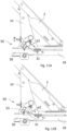
- Figs. 11A and 11B show a zoomed-in detailed view of the adjustment shown in Figs. 10D and 10E where it is clearly shown that the sledge arm 31 and the lifting arm 14 are connected to form a first angle ⁇ 1 between each other, and that the first angle ⁇ 1 formed between the sledge arm 31 and the lifting arm 14 is configured to be changed into a second angle ⁇ 2 when the adjustment system 50 is adjusted. In the embodiment shown, this is carried out by adjusting the position of the first end 31a of the sledge arm 31 by means of the adjustment system 50.
- the first angle ⁇ 1 may be considered as an outset angle or pre-defined angle, typically forming part of factory settings in a condition of supply of the lifting device 10.
- Fig. 12 shows a close-up bottom perspective view of the adjustment system, where it is clearly shown that the push arm 40 comprises indications for adjustment to different roof inclinations.
- the indications are numerical values, ranging from 15 to 60, corresponding to respective degrees. These values indicate and correspond to the desired roof inclination that the user should adjust the lifting device 50.
- the numerical values shown on the push arm are 15, 30, 45 and 60 corresponding to roof inclinations of 15, 30, 45 and 60 degrees.
- a marking indicating the ascending or descending order of the numerical values is included in the embodiment shown. In alternative embodiments, higher or lower values of roof inclinations than those indicated in the embodiments shown may be achieved.
Landscapes
- Engineering & Computer Science (AREA)
- Architecture (AREA)
- Civil Engineering (AREA)
- Structural Engineering (AREA)
- Window Of Vehicle (AREA)
Abstract
Description
- The present invention relates to a roof window with a stationary primary frame, at least one secondary frame, such as a sash and/or an intermediate frame, and a lifting device comprising a lifting arm inserted between the primary frame and the at least one secondary frame, the lifting arm having a first end and a second end, the second end being rotatably connected to the secondary frame, the lifting device furthermore comprising a spring assembly configured to be coupled to a sledge, the lifting device further comprising a push arm having a first end and a second end, the second end being rotatably connected to the lifting arm, and the lifting device further comprising a sledge arm having a first end and a second end, the second end being rotatably connected to the sledge.
- Windows for installation in an inclined roof surface may be provided in a number of varieties and include more or less complicated operational structures to allow opening of the secondary frame, or sash, and to fulfil other functions, such as ventilation. Such roof windows include the type hinged at or near the centre, the top-hinged type, and finally the roof windows that are top-hinged during normal operation but in which the sash is able to perform a rotating movement substantially at a centre axis, either for cleaning or for providing an alternative manner of operation. Roof windows of the top-hinged type have a first hinge axis provided by a top hinge arrangement to provide a first operational condition, whereas rotation of the sash in a second operational condition is performed by means of an intermediate frame in which the sash is hinged to provide a secondary hinge axis. Typically, one hinge of the hinge arrangement will be located at either side of the roof window to define a substantially horizontal hinge axis.
- Examples of top-hinged windows with a second operational condition are for instance disclosed in Applicant's
WO-A-89/10460 EP 0 733146 B1EP 1 873 323 B1 ,EP 2 762 665 A2WO 2019101281 A1 . To make it possible to rotate the window sash approximately 180° to a convenient cleaning position, the sash structure is connected with an intermediate frame with frame arms, which in the closed position of the window are positioned between the upper parts of the frame and sash side members, and which during normal use of the window as a top-hung window follow the sash side members. - Furthermore, the opening of a roof window and the force required to operate the window is affected by the inclination of the roof in which the window is installed.
- In roof windows in which the operation takes place either entirely or partially about a hinge axis at the top, it is known to balance at least part of the weight of the movable components by means of a lifting device. The purpose of this arrangement is to facilitate opening the window, and the dimensions may be chosen so that a spring can retain the top-hinged frame in equilibrium in a desired opening position.
- Such a lifting device is for instance disclosed in the Applicant's
WO2019/101281 A1 where a spring assembly acts as a force balancing element to the pane-carrying frame by operating on a lifting arm attached to the frame. - Another example of a lifting device is disclosed in Applicant's
4 390 030 A1 -
EP 4 215 706 A1 - However, although the lifting device in the above example is to some extent capable of providing the desired force balance, there is still room for improvement.
- With this background it is an object of the present invention to provide a roof window with a lifting device having an increased design flexibility allowing the desired movement pattern and ease of operability while adjusting to different roof inclinations.
- This is achieved with a roof window of the kind mentioned in the introduction, which is further characterised in that the lifting device further comprises an adjustment system, that the first end of the lifting arm is rotatably connected to the sledge slidably connected to the primary frame in a sledge guide, that the first end of the sledge arm is rotatably connected to the lifting arm via the adjustment system, and that the sledge arm and the lifting arm are connected to form a first angle between each other, wherein the angle is configured to be changed into a second angle by adjusting the position of the first end of the sledge arm by means of the adjustment system.
- The adjustment system thus allows angle between the sledge arm and the lifting arm to assume different angles relative to each other, namely such that the first angle may be considered as an outset angle or pre-defined angle, typically forming part of factory settings in a condition of supply of the lifting device, and by means of the adjustment system, the first angle is changed into the second angle.
- This arrangement of arms in the form of the lifting arm, push arm and sledge arm provides an alternative connection of the lifting arm to the sledge and a versatile solution for adjusting to roof inclination. The combined effect of the second end of the lifting arm being rotatably fixed to the secondary frame and the use of a push arm being at one end rotatably fixed to the sledge guide and at the other end rotatably fixed to the lifting arm provides a point of rotation around the push arm allowing the first end of the lifting arm to have a larger degree of freedom while still having the necessary stability to securely lift the secondary frame and without requiring a large force to operate the roof window.
- The sledge arm provides a link between the lifting arm and the sledge. As such, the lifting arm is rotatably connected to the first end of the sledge arm, and the sledge is rotatably fixed the second end of the sledge arm. Thereby, the lifting arm will rotate about the sledge arm connection during opening and closing of the roof window. The sledge arm has the advantage of increasing the mobility of the lifting arm relative to the sledge because it acts as a link connection between the sledge and the lifting arm. The sledge arm is preferably connected to the lifting arm at a point proximate the first end of the lifting arm.
- The adjustment system provides a mechanism for adjusting the balance between the weight of the pane-carrying sash with the force provided by the spring assembly. The weight of the pane-carrying sash is at least partially carried by the lifting arm when the roof window is in an open position and the lifting arm is arranged such that the weight of the pane-carrying sash acts as a pulling force on the spring in the spring assembly. The stretched spring provides a spring force towards the equilibrium position of the spring which forces the pane-carrying sash towards an open position. The weight carried by the lifting arm depends on the roof inclination of the roof in which the roof window is installed. The balance between the spring force and the force from the weight of pane-carrying sash acting on the lifting arm may therefore change when the roof inclination is changed. The adjustment system is arranged to adjust the balance between the force exerted by the lifting arm on the pane-carrying sash and the weight of the pane-carrying sash. The adjustment system is arranged such that the opening angle of the roof window is not substantially affected during adjustment of the adjustment system. That means that the adjustment to a different roof inclination is possible without affecting the opening angle of the roof window. The adjustment system may be adjusted to balance roof window for roof inclinations in the range of 15 - 60°.
- Compared to
EP 4 215 706 A1 - In an embodiment, the adjustment system comprises an adjustment screw and an adjustment bushing, and wherein the first end of the sledge arm may be connected to the lifting arm via the adjustment screw and the adjustment bushing. The adjustment screw may act as a connecting link between one or more elements of the roof window, where one element is the lifting arm, allowing the connected elements to be moved relative to each other when the adjustment screw is adjusted. Generally, the adjustment screw comprises an adjustment screw shaft, an adjustment screw wheel, and an adjustment screw top. In general, the adjustment screw is constrained by the opening of the adjustment arm. In preferred embodiments, the adjustment screw is connected to the lifting arm via the adjustment screw top. The adjustment screw top is preferably rotatably connected to the lifting arm. Thereby, the adjustment screw may rotate relative to the adjustment arm when the adjustment screw is adjusted. Alternatively, the adjustment screw may be fixed to the lifting arm and the adjustment screw is thereby stationary relative to the lifting arm when the adjustment screw is adjusted.
- One or more elements of the roof window may be connected to the adjustment screw shaft. The position of the one or more elements on the adjustment screw shaft is arranged to be adjusted when the adjustment screw is manipulated. The adjustment screw wheel is arranged to be manipulated by an external force such as the force from a screw bit in order to rotate the adjustment screw. By adjustment of the adjustment screw, the one or more elements connected to the adjustment screw shaft is arranged to be moved relative to the lifting arm. This arrangement changes the balance between the weight of the pane-carrying frame and the force exerted by the lifting arm on the pane-carrying frame from the pull of the spring assembly.
- The adjustment bushing may provide a low friction connection between the adjustment screw and the adjustment arm and sledge arm, respectively.
- In a further embodiment, the lifting device further comprises an adjustment arm with a first end rotatably connected to the adjustment system and a second end rotatably connected to the lifting arm. The adjustment arm may be connected to the adjustment screw comprised in the adjustment system. Even more preferably, the adjustment arm is connected to the adjustment screw shaft. As previously described, the adjustment screw is preferably connected to the lifting arm through an adjustment screw top, and one or more elements are connected to the adjustment screw shaft. The adjustment arm may reduce the friction between the moving part of the lifting device during adjustment of the in the adjustment system, by acting as a constraint on the adjustment screw. By the second end of the adjustment arm being rotatably fixed to the lifting arm and the first end rotatably fixed to the adjustment screw, the adjustment screw is constrained to move in the arc provided by rotating the adjustment arm around its connection point with the adjustment arm.
- In a still further embodiment, the adjustment screw may be arranged in an opening of the lifting arm and/or the sledge arm may be connected to the adjustment screw inside the opening of the lifting arm. The forces acting on the adjustment screw may drive the adjustment screw towards a surface of the lifting arm resulting in the adjustment system and the lifting arm colliding causing unwanted friction and tear on the system and on the sledge. Alternatively, and/or additionally, the forces acting on the adjustment screw may cause a strain on the adjustment screw causing unwanted wear and tear on the system.
- The opening of the lifting arm in which the adjustment screw may be arranged, may be shaped according to the adjustment arm such that the second end of the adjustment arm travels along this opening.
- The sledge arm may be connected to the lifting arm via the adjustment screw, and the adjustment arm may be connected to the lifting arm via the adjustment screw.
- As such, both the adjustment arm and the sledge arm may be adjusted via the adjustment screw and may be adjusted simultaneously. Additionally, this configuration provides a simple connection between the adjustment screw, the adjustment arm, the sledge arm, and the lifting arm.
- Indications such as numerical values, letters or marks for indicating a roof inclination may be provided on the push arm and/or the lifting arm and/or at another location or locations in proximity of the adjustment system. Such indications may preferably be provided on the push arm. The sledge arm may be arranged in proximity of the push arm and when the sledge arm is connected to the lifting arm via the adjustment screw, the sledge arm will move relative to the push arm when the6 adjustment screw is adjusted. As such, the sledge arm may serve as a pointer towards indications on the push arm to indicate a roof inclination.
- In yet another embodiment, the lifting arm may comprise a first lifting arm and a second lifting arm arranged symmetrically with respect to a central plane. This may increase the balance and stability of the lifting device. It may further ease the operation of the roof window and the assembling of the lifting device.
- The adjustment arm may be arranged between the first lifting arm and the second lifting arm. Alternatively, the adjustment arm may comprise a first adjustment arm and a second adjustment arm positioned on the exterior side of the first lifting arm and the second lifting arm.
- The push arm may comprise a first push arm and a second push arm arranged symmetrically with respect to the central plane. The first push arm and the second push arm may be positioned on opposite sides of the lifting arm. This may facilitate the easy operation of the window, resulting in a stable and robust lifting device.
- The sledge arm may comprise a first sledge arm and a second sledge arm arranged symmetrically with respect to the central plane. This configuration may contribute to the balancing and stability of the lifting device, as well as facilitate the manufacturing process of the lifting device since not many different configurations of the arm would have to be produced. The first and second sledge arms may be positioned between a first and second lifting arm. Alternatively, the first and second sledge arm may be positioned on opposite sides of the lifting arm.
- The second end of the push arm may be connected to the lifting arm at a position between the first end of the lifting arm and the second end of the lifting arm.
- This may provide a larger range of motion for the first end of the lifting arm.
- The sledge may further comprise at least two runners, each runner being slidably connected to a track in the sledge guide.
- The runners may provide a stable connection between the sledge and the sledge guide that allows the sledge to slide in the sledge guide at low friction. The track may comprise a straight portion and/or a curved portion.
- The at least two runners may comprise a front runner sliding in a front track positioned towards a first end of the sledge guide and a back runner in a back track positioned towards a second end of the sledge guide. The combination of a front runner and a back runner may provide a balanced support of the sledge in the sledge guide.
- The front runner may comprise a first front runner and a second front runner positioned on opposite sides of the lifting arm. This may provide an open space between the first and second front runner allowing the first end of the lifting arm to be coupled to the sledge in proximity of the front runner. Alternatively, the first front runner and the second front runner may be coupled together.
- According to another aspect of the invention, a method for adjusting the lifting device of the roof window is provided comprising the step of: applying an external force to the adjustment system such that the first angle is changed into the second angle value.
- The adjustment of the lifting device to a different roof inclination may be performed by the adjustment of the first end of the sledge arm on the adjustment screw, thus balancing the forces acting on the lifting arm.
- Other presently preferred embodiments and further advantages will be apparent from the subsequent detailed description and drawings.
- In the following description, embodiments of the invention will be described with reference to the drawings, in which
-
Fig. 1A is a perspective view of a roof window in an embodiment of the invention, seen from an interior side. -
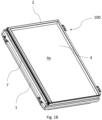
Fig. 1B is perspective view of a roof window in an embodiment of the invention, seen from an exterior side. -
Fig. 1C is a side view of a roof window in an embodiment of the invention, with the sash in an open position. -
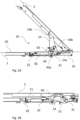
Fig. 2A is a side view of a lifting device for a roof window in an embodiment according to the invention in an open position. -
Fig. 2B is a side view of a lifting device for a roof window in an embodiment according to the invention in a closed position. -
Fig. 3A is a perspective exploded view of a connection between an adjustment screw, an adjustment bushing, and an adjustment arm in an embodiment according to the invention. -
Fig. 3B is a perspective exploded view of a connection between an adjustment screw arranged in an opening of a lifting arm in an embodiment according to the invention. -
Fig. 3C is a perspective exploded view of a connection between a sledge arm, adjustment system, and a lifting arm in an embodiment according to the invention. -
Fig. 4A is a side view of a lifting arm connected with a sledge arm through an adjustment system in a default position. -
Fig. 4B is a side view of the lifting arm ofFig. 4A wherein the sledge arm is rotated relative to the lifting arm. -
Fig. 4C is a side view of the lifting arm ofFig. 4A and 4B wherein the adjustment system is adjusted thereby changing the connection point between the adjustment system and the sledge arm. -
Fig. 5 . Is a perspective exploded view of a connection between the lifting arm and the sledge arm. -
Fig. 6 is a perspective view of an assembly comprising the lifting arm, the sledge arm, the adjustment arm and the adjustment system in an embodiment according to the invention. -
Fig. 7 is a perspective view of a lifting device shown before installed in a sledge connected with a sledge guide in an embodiment according to the invention. -
Fig. 8 is a perspective view of a lifting device for a roof window in an embodiment according to the invention showing a central plane P. -
Fig. 9 is a front view of a lifting device for a roof window in an embodiment according to the invention showing the central plane P and the symmetrical arrangement of the lifting arm, sledge arm, and adjustment arm, in an embodiment according to the invention. -
Fig. 10A is a close-up of a side view of an adjustment screw arranged in an opening of the lifting arm in an embodiment according to the invention. -
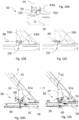
Fig. 10B shows the embodiment ofFig. 10A in which a tool is inserted to provide an external force on the adjustment system. -
Fig. 10C shows the embodiment ofFigs. 10A and 10B in which the tool acts on the adjustment screw wheel. -
Fig. 10D shows the embodiment ofFigs. 10A-10C in which an external force is provided by means of rotating the external tool thereby adjusting the adjustment screw. -
Fig. 10E shows the embodiment ofFigs. 10A-10D in which the position of the sledge arm on adjustment screw has been changed by means of adjustment of the adjustment screw, thereby changing an angle between the sledge arm and the lifting arm. -
Fig. 11A - 11B show the changing angle between the sledge arm and the lifting arm when the adjustment screw is adjusted. -
Fig. 12 is a close-up of a bottom perspective view of an adjustment system in an embodiment according to the invention. - In the following, embodiments of a lifting device and roof window will be described in further detail. When referring to the figures, the terms up, down, upwards, downwards, top and bottom are taken relative to how the figures are displayed. A front view is taken from the hinge and viewing towards the window frame. A view from behind is therefore taken as viewed from the frame towards the hinge. A longitudinal direction is, if nothing else is mentioned, longitudinal along the length of a member. It is to be understood that the arrangement shown in a horizontal orientation is not the normal orientation as the window is installed on an inclined roof. An interior side faces towards the interior of the building where the window is installed, while an exterior side faces on the opposite direction towards the exterior of the building.
- Reference numerals refer to similar elements across various embodiments and figures described herein.
- Referring initially to
Figs 1A and1B , aroof window 100 is shown. Theroof window 100 is intended to be installed in or on an inclined roof surface (not shown). - The
roof window 100 comprises aprimary frame 1, a secondary frame which in the following will be referred to as asash 2 but which could also include an intermediate frame connected partly to theprimary frame 1, partly to a separate, glass-carrying unit functioning as a sash, and apane 4. - Generally, the roof window comprises a windowpane comprising at least two layers of glass, preferably at least three layers of glass. The window may comprise an Insulating Glazing Unit (IGU).
- The
primary frame 1 comprises a set of frame members including a top frame member, two side frame members and a bottom frame member. Correspondingly, thesash 2 comprises a set of sash members including a top sash member, two side sash members and a bottom sash member. While theprimary frame 1 andsash 2 are described as rectangular structures, some principles of the presented concepts may be applicable to other geometrical shapes as well. - The
pane 4 comprises a number of edge portions generally associated to members of thesash 2. Anexterior pane surface 4e defines a plane of theroof window 100 in an assembled condition of theroof window 100. The assembled condition of theroof window 100 is achieved when main components of theprimary frame 1 andsash 2 have been assembled and theprimary frame 1 andsash 2 are connected to each other, for instance in an installed position when theroof window 100 is ready for use. Correspondingly, an assembled condition of thesash 2 is achieved once main components of thesash 2 have been assembled, and an assembled condition of theprimary frame 1 when main components of theprimary frame 1 are assembled. The term "main components" is to be understood as encompassing primary parts of the roof window necessary to perform all operational functions, and not including accessories or auxiliary equipment. - An
interior pane surface 4i faces the interior, typically a room of a building subjacent the roof surface in which theroof window 100 is installed. - In the embodiments shown, the
sash 2 is openable relative to theprimary frame 1, to obtain one or more open positions. In such open positions, thesash 2 andpane 4 are moved out of the plane of theroof window 1. As will be described in the following, thesash 2 is shown as being top-hung, i.e., during normal use, thesash 2 is rotated about a substantially horizontal hinge axis at or near the top frame member and top sash member at the top of theroof window 100. It is however conceivable to apply some principles of the presented concepts for roof windows on different types of windows having other opening patterns. - Further details shown in
Fig. 1A include anoperating assembly 5, here shown as a handle. Other operating assemblies may be present as well. - Also shown in
Fig. 1B is a representative mounting bracket forming part of a plurality of mounting brackets forming a load-transferring connection between theroof window 100 and a surrounding roof structure (not shown). Such a roof structure may include rafters and battens, plywood or other construction materials. - An insulating
frame 7 is shown. Insulation by an insulating frame is optional and may be provided along only some of the frame members or as shown surrounding all four frame members. - Referring to
Fig. 1C , theroof window 100 is shown in a top-hung configuration. The roof window is top-hung, i.e., hinged at the top, by means of a hinge assembly (not shown) connecting the primary frame with the secondary frame. - The hinge assembly is configured in such a way that it allows the
sash 2 to be top-hung in a first operational condition corresponding to normal use. That is, during normal use thesash 2 is rotated about a substantially horizontal first hinge axis at or near the top frame member and top sash member between a closed position and an open position. - To assist the user in opening the
sash 2, alifting device 10 is provided as will be described in the following. Referring now also toFig. 2A , the liftingdevice 10 comprises a liftingarm 14 inserted between theprimary frame 1 and the at least one secondary frame, here thesash 2. The liftingdevice 10 furthermore comprises aspring assembly 20 configured to be coupled to asledge 30, and apush arm 40. - In
Fig. 2A an embodiment of thelifting device 10 is shown from a side view with one side of thesledge guide 16 removed thereby showing thesledge 30 in connection with thespring assembly 20. The liftingarm 14 is inserted between theprimary frame 1 and thesash 2 such that the liftingarm 14 has afirst end 14a in connection with thesledge 30 and asecond end 14b connected to thesash 2. - The lifting
arm 14 is connected to thesledge guide 16 via thepush arm 40. Thepush arm 40 has afirst end 40a rotatably connected to thesledge guide 16 and asecond end 40b rotatably connected to the liftingarm 14, in the embodiment shown by means of afirst rivet 42i and a second rivet 42ii as shown in more detailFig. 5 . - The
sledge 30 is attached to thespring assembly 20 which is arranged to exert a force on thesledge 30 in a condition of use of theroof window 100. Thesledge 30 may be uncoupled from thespring assembly 20, as shown inFig. 2B . This may, as an example, be an advantage during installation of the roof window where a spring force acting on thesledge 30 may make it difficult to handle the roof window. In the cases where the lifting device is installed in the roof window according to its intended use, thesledge 30 and thespring assembly 20 are initially in an uncoupled state. Thespring assembly 20 and thesledge 30 are then coupled by opening the roof window resulting in thesledge 30 sliding towards a coupling device such as ahook 21 attached to a spring comprised in thespring assembly 20. Such a coupling may for example be realized by thesledge 30 comprising acoupling plate 32 for coupling thesledge 30 to thespring assembly 20. Opening the roof window results in thesledge 30 engaging with thehook 21 and once the roof window is subsequently closed, thesledge 30 will slide in a direction away from thespring assembly 20 towards the top hinge of theroof window 100 and the spring, now coupled to thesledge 30, will exert a pulling force on thesledge 30 and provide a resistance against the closing of the roof window. - The pulling force of the
spring assembly 20 and the weight of the movable parts of theroof window 100 are preferably balanced such that thesash 2 of theroof window 100 can be positioned in an open position without forcing it to close due to its own weight or forcing it to open further due to the pulling force applied by the spring of thespring assembly 20. This balance is affected by the inclination of the roof that the roof window is installed in. The spring in thespring assembly 20 may be adjusted to balance the roof window to a specific roof inclination. If the roof window is installed on a roof with a roof inclination different than the intended inclination, the spring force acting on thesledge 30 will not be balanced to the weight of the movable parts of the roof window. In one example, the spring may exert too much force on the window thereby forcing the window to open further. In another example, the spring may be too weak, and the window will close due to its own weight. In both cases, the window may be difficult for the user to operate and potentially hazardous. - To easily adjust the
roof window 100 according to roof inclination, anadjustment system 50 may be used. Theadjustment system 50 may be used to adjust the roof window for roof inclinations in the range of 15 - 60°. - An embodiment of the
adjustment system 50 is shown in greater detail inFigs. 3A - 4C . Theadjustment system 50 is connected to anadjustment arm 52 which in turn is connected to the other components of thelifting device 10 as will be described in further detail below. -
Fig. 3A shows anadjustment screw 53 with anadjustment screw shaft 53i, an adjustment screw wheel 53ii, and an adjustment screw top 53iii. In the embodiment shown, theadjustment arm 52 is a two-part component comprising afirst adjustment arm 521 and asecond adjustment arm 522 and is coupled to anadjustment bushing 54. -
Fig. 3B shows the assembly ofFig. 3A in connection with the liftingarm 14 which is here formed to comprise afirst lifting arm 141 and asecond lifting arm 142. Thefirst lifting arm 141 and thesecond lifting arm 142 are connected to each other by one or more lifting arm rivets 57. InFig. 3B , theadjustment system 50 comprising theadjustment screw 53 is shown as being accommodated between thefirst lifting arm 141 and thesecond lifting arm 142 and in anopening 15. Theadjustment arm 52 has afirst end 52a connected to theadjustment system 50 via theadjustment bushing 54. A second end of theadjustment arm 52b is rotatably connected to the liftingarm 14 allowing theadjustment arm 52 to travel along a path in theopening 15 of the lifting arm. In the embodiment shown, theopening 15 of the lifting arm is arch-shaped but could in principle have any shape allowing suitable movement. The adjustment screw wheel 53ii is accommodated in aseparate opening 17 in the liftingarm 14. Preferably the adjustment screw is connected to the liftingarm 14 via the adjustment screw top. -
Fig. 3C shows asledge arm 31 with afirst end 31a rotatably connected to the liftingarm 14 and asecond end 31b rotatably connected to thesledge 30, not shown inFig. 3C . Thesledge arm 31 is connected to theadjustment bushing 54. In the embodiment shown, thesledge arm 31 is a two-part component as will be described below. - Thus, the
adjustment arm 52 is arranged in the liftingarm 14 between thefirst lifting arm 141 andsecond lifting arm 142, and thesledge arm 31 is arranged on the outside of the liftingarm 14. -
Figs 4A - 4C show the assembly of the liftingarm 14 and thesledge arm 31 fromFigs 3A - 3C .Fig. 4B shows how asecond end 31b of thesledge arm 31 is arranged to rotate around theadjustment bushing 54 andFig. 4C shows how afirst end 31a of thesledge arm 31 is arranged to move along theadjustment screw shaft 53i upon adjustment of theadjustment screw 53. -
Fig. 5 shows apush arm 40 with afirst end 40a configured for being attached to the sledge guide (not shown) and asecond end 40b being rotatably connected to the liftingarm 14. InFig. 5 , the push arm comprises afirst push arm 401 and asecond push arm 402 arranged on opposite sides of the liftingarm 14. The liftingarm 14 is rotatably connected to the sash 2 (not shown) by means of arivet 41. The connection between the liftingarm 14 and thesash 2 is shown inFigs. 8 and10D-10E . - The assembly of the lifting
arm 14, thepush arm 40, theadjustment system 50, theadjustment arm 52, and thesledge arm 31 according to one embodiment of the invention, is shown inFig. 6 . - Referring now to
Fig. 7 , an embodiment of thesledge 30 and thepush arm 40 being arranged in thesledge guide 16 is shown. The sledge inFig. 7 has afirst front runner 701 and asecond front runner 702 arranged to be slidably connected to afront track 43a located on each side of thesledge guide 16, and aback runner 71 arranged to be slidably connected to aback track 43b located on each side of thesledge guide 16. The first and secondfront runners front runner 70 are in this embodiment shown as two separate runners, but may in other embodiments be coupled to form asingle front runner 70. -
Fig. 8 shows alifting device 10 according to the invention with the liftingarm 14 inserted between theprimary frame 1 and thesash 2. Thesledge guide 16 extends along a length axis in a length direction L. When the window is in a closed position the liftingarm 14 also extends in the length direction L. A height axis extends in a height direction H perpendicular to the length direction L. The height axis extends perpendicularly to the pane of the roof window when the lifting device is installed in the roof window. The length axis and the height axis define a central plane P. - Generally, the lifting
arm 14 of the embodiment shown comprises afirst lifting arm 141 and asecond lifting arm 142 arranged symmetrically with respect to the central plane P. Forming at least the liftingarm 14 as a two-part component so that the forces exerted by the liftingarm 14 onto the central plane P are balanced provides for an advantageous load distribution within the liftingdevice 10. That is, the forces resulting from the weight of the movable components of theroof window 100 are aligned with respect to the central plane P. - The
push arm 40 comprises afirst push arm 401 and asecond push arm 402 arranged symmetrically with respect to the central plane P. Thesledge arm 31 comprises afirst sledge arm 311 and asecond sledge arm 312 arranged symmetrically with respect to the central plane P. Finally, theadjustment arm 52 comprises afirst adjustment arm 521 and asecond adjustment arm 522 arranged symmetrically with respect to the central plane P and extending along the central plane P, while theadjustment screw 53 extends in the central plane P. - The symmetrical arrangement of the lifting device components provides a lifting device where forces from the pane and other movable components of the roof window are aligned with respect to the central plane P. This ensures minimal torque on the individual parts of the lifting device and stabilizes the lifting device and the roof window in general.
- Turning now to
Figs. 10A-10E embodiments comprising anadjustment system 50 according to the disclosure are shown. Theadjustment system 50 is shown comprising anadjustment screw 53 provided within the contours of the liftingarm 14 such as to be accessible via an opening in the liftingarm 14 as will be described below. -
Fig. 10B shows how the adjustment system is adjusted by applying an external force. In this embodiment the external force is applied via ascrew bit 60 to the adjustment screw wheel 53ii. In the embodiments shown inFigs. 10A-10C the liftingarm 14 is arranged to receive ascrew bit 60 through an opening in the liftingarm 14. In the embodiment shown, the opening is provided as a space between thefirst lifting arm 141 and thesecond lifting arm 142 such that thescrew bit 60 may be inserted from the back of the liftingarm 14. As such, theadjustment system 50 is most easily adjusted when theroof window 100 is in an open position. The opening for such a screw bit may alternatively and/or additionally by arranged on another side such as the front or on one or both sides of the lifting arm, for instance via theopening 15 described in the above. By having an opening on the side of the liftingarm 14 it is possible to adjust theadjustment system 50 in both the open and closed positions of the roof window. - In
Figs. 10D and 10E it is shown how adjusting theadjustment system 50 changes the position of thefirst end 31a of thesledge arm 31 relative to the liftingarm 14 by moving along theadjustment screw 53, thereby changing the force balance between pulling force from thespring assembly 20 and the weight of the window, making it possible to adjust theroof window 100 for different roof inclinations. Thefirst end 31a of thesledge arm 31 is therefore shown having two different positions relative to the liftingarm 14 corresponding to adjustment to two different roof inclinations. -
Figs. 11A and 11B show a zoomed-in detailed view of the adjustment shown inFigs. 10D and 10E where it is clearly shown that thesledge arm 31 and the liftingarm 14 are connected to form a first angle α1 between each other, and that the first angle α1 formed between thesledge arm 31 and the liftingarm 14 is configured to be changed into a second angle α2 when theadjustment system 50 is adjusted. In the embodiment shown, this is carried out by adjusting the position of thefirst end 31a of thesledge arm 31 by means of theadjustment system 50. The first angle α1 may be considered as an outset angle or pre-defined angle, typically forming part of factory settings in a condition of supply of thelifting device 10. -
Fig. 12 shows a close-up bottom perspective view of the adjustment system, where it is clearly shown that thepush arm 40 comprises indications for adjustment to different roof inclinations. In this embodiment, the indications are numerical values, ranging from 15 to 60, corresponding to respective degrees. These values indicate and correspond to the desired roof inclination that the user should adjust thelifting device 50. By moving the position of the first end of thesledge arm 31 on theadjustment screw 53 to a specific numerical value, the user is able to adjust the lifting device of the roof window to the desired roof inclination. In the embodiment shown inFigs 11A, 11B and12 , the numerical values shown on the push arm are 15, 30, 45 and 60 corresponding to roof inclinations of 15, 30, 45 and 60 degrees. Furthermore, a marking indicating the ascending or descending order of the numerical values is included in the embodiment shown. In alternative embodiments, higher or lower values of roof inclinations than those indicated in the embodiments shown may be achieved. -
- 1
- primary frame
- 2
- secondary frame / sash
- 4
- pane
- 4i
- interior pane surface
- 4e
- exterior pane surface
- 5
- operating assembly
- 7
- insulating frame
- 10
- lifting device
- 14
- lifting arm
- 14a
- first end of lifting arm
- 14b
- second end of lifting arm
- 15
- opening of lifting arm
- 16
- sledge guide
- 17
- separate opening
- 20
- spring assembly
- 21
- hook
- 30
- sledge
- 31
- sledge arm
- 31a
- first end of sledge arm
- 31b
- second end of sledge arm
- 32
- coupling plate
- 40
- push arm
- 40a
- first end of push arm
- 40b
- second end of push arm
- 41
- rivet
- 42i
- first rivet
- 42ii
- second rivet
- 43a
- front track
- 43b
- back track
- 50
- adjustment system
- 52
- adjustment arm
- 52a
- first end of adjustment arm
- 52b
- second end of adjustment arm
- 53
- adjustment screw
- 53i
- adjustment screw shaft
- 53ii
- adjustment screw wheel
- 53iii
- adjustment screw top
- 54
- bushing
- 57
- lifting arm rivet
- 60
- screw bit
- 70
- front runner
- 71
- back runner
- 100
- roof window
- 141
- first lifting arm
- 142
- second lifting arm
- 311
- first sledge arm
- 312
- second sledge arm
- 401
- first push arm
- 402
- second push arm
- 521
- first adjustment arm
- 522
- second adjustment arm
- 701
- first front runner
- 702
- second front runner
- P
- central plane
- L
- length direction
- H
- height direction
- α1
- first angle
- α2
- second angle
Claims (12)
- A roof window, comprisinga stationary primary frame (1),at least one secondary frame (2) such as a sash (2) and/or an intermediate frame, anda lifting device (10) comprising a lifting arm (14) inserted between the primary frame (1) and the secondary frame (2), the lifting arm (14) having a first end (14a) and a second end (14b), the second end (14b) being rotatably connected to the secondary frame (2),the lifting device (10) furthermore comprising a spring assembly (20) configured to be coupled to a sledge (30),the lifting device (10) further comprising a push arm (40) having a first end (40a) and a second end (40b), the second end (40b) being rotatably connected to the lifting arm (14), andthe lifting device (10) further comprising a sledge arm (31) having a first end (31a) and a second end (31b), the second end (31b) being rotatably connected to the sledge (30),characterised in thatthe lifting device (10) further comprises an adjustment system (50), thatthe first end (14a) of the lifting arm (14) is rotatably connected to the sledge (30) slidably connected to the primary frame (1) in a sledge guide (16), thatthe first end (31a) of the sledge arm (31) is rotatably connected to the lifting arm (14) via the adjustment system (50), and thatthe sledge arm (31) and the lifting arm (14) are connected to form a first angle (α1) between each other, wherein the first angle (α1) is configured to be changed into a second angle (α2) by adjusting the position of the first end (31a) of the sledge arm (31) by means of the adjustment system (50).
- A roof window (100) according to claim 1, wherein the adjustment system (50) comprises an adjustment screw (51) and an adjustment bushing (53), and wherein the first end (31a) of the sledge arm (31) is connected to the lifting arm (14) via the adjustment screw (51) and the adjustment bushing (54).
- A roof window (100) according to any one of the preceding claims, wherein the lifting device (10) further comprises an adjustment arm (52), with a first end (52a) rotatably connected to the adjustment system (50) and a second end (52b) rotatably connected to the lifting arm (14).
- A roof window (100) according to any one of claims 2 to 3, wherein the adjustment screw (51) is arranged in an opening of the lifting arm (14), and wherein the sledge arm (31) is connected to the adjustment screw (53) in the opening of the lifting arm (14).
- A roof window (100) according to any one of the preceding claims, wherein the lifting arm (14) comprises a first lifting arm (141) and a second lifting arm (142) arranged symmetrically with respect to a central plane (P).
- A roof window (100) according to any one of the preceding claims, wherein the sledge arm (31) comprises a first sledge arm (311) and a second sledge arm (312) arranged symmetrically with respect to a central plane (P).
- A roof window (100) according to any of the preceding claims, wherein the push arm (40) comprises a first push arm (401) and a second push arm (402) arranged symmetrically with respect to a central plane (P).
- A roof window (100) according to claim 5, wherein the adjustment arm (52) is arranged between the first lifting arm (141) and the second lifting arm (142).
- A roof window (100) according to any of one of the preceding claims, wherein the second end (40b) of the push arm (40) is connected to the lifting arm (14) at a position between the first end (14a) of the lifting arm (14) and the second end (14b) of the lifting arm (14).
- A roof window (100) according to any one of the preceding claims, wherein the sledge (30) comprises at least two runners (70, 71), each runner being slidably connected to a track (43a, 43b) in the sledge guide (16).
- A roof window (100) according to claim 1, wherein the secondary frame comprises a sash (2).
- A method for adjusting a lifting device for a roof window (100) according to any one of claims 1 to 11, the method comprising the step of:
applying an external force to the adjustment system (50) such that the first angle (α1) is changed into the second angle (α2).
Applications Claiming Priority (1)
| Application Number | Priority Date | Filing Date | Title |
|---|---|---|---|
| DKPA202370602A DK182066B1 (en) | 2023-12-08 | 2023-12-08 | A roof window and a method for adjusting a lifting device of the roof window |
Publications (1)
| Publication Number | Publication Date |
|---|---|
| EP4567238A1 true EP4567238A1 (en) | 2025-06-11 |
Family
ID=95706307
Family Applications (1)
| Application Number | Title | Priority Date | Filing Date |
|---|---|---|---|
| EP24218103.0A Pending EP4567238A1 (en) | 2023-12-08 | 2024-12-06 | A roof window with an adjustable lifting device and a method for adjusting a lifting device of the roof window |
Country Status (3)
| Country | Link |
|---|---|
| EP (1) | EP4567238A1 (en) |
| CN (1) | CN223753902U (en) |
| DK (1) | DK182066B1 (en) |
Citations (7)
| Publication number | Priority date | Publication date | Assignee | Title |
|---|---|---|---|---|
| WO1989010460A1 (en) | 1988-04-08 | 1989-11-02 | V. Kann Rasmussen Industri A/S | A window, especially for installation in an inclined roof |
| EP0733146B1 (en) | 1993-12-10 | 1997-06-11 | V. Kann Rasmussen Industri A/S | A window, particularly for installation in an inclined roof surface |
| EP0874103A2 (en) * | 1997-04-24 | 1998-10-28 | Dörken Tageslichtsysteme GmbH & Co Produktions KG | Tilting window for a pitched roof |
| EP1873323B1 (en) | 2006-06-27 | 2011-05-18 | VKR Holding A/S | A lifting device and a window comprising such a lifting device |
| EP2762665A2 (en) | 2013-02-01 | 2014-08-06 | VKR Holding A/S | A pivot hinge fitting with engagement means and a roof window comprising a set of such pivot hinge fittings |
| WO2019101281A1 (en) | 2017-11-24 | 2019-05-31 | Vkr Holding A/S | Roof window with a primary frame and at least one secondary frame, method for installing such a roof window and method for dismantling a secondary frame of the roof window |
| EP4215706A1 (en) | 2020-09-15 | 2023-07-26 | Strepetov, Andrey Borisovich | Friction hinge for top-hung outwardly opening windows |
Family Cites Families (1)
| Publication number | Priority date | Publication date | Assignee | Title |
|---|---|---|---|---|
| PL220967B1 (en) * | 2007-11-02 | 2016-02-29 | Fakro Pp Spółka Z Ograniczoną Odpowiedzialnością | Lifting-rotating window, especially roof window |
-
2023
- 2023-12-08 DK DKPA202370602A patent/DK182066B1/en active IP Right Grant
-
2024
- 2024-12-06 EP EP24218103.0A patent/EP4567238A1/en active Pending
- 2024-12-06 CN CN202423015420.5U patent/CN223753902U/en active Active
Patent Citations (7)
| Publication number | Priority date | Publication date | Assignee | Title |
|---|---|---|---|---|
| WO1989010460A1 (en) | 1988-04-08 | 1989-11-02 | V. Kann Rasmussen Industri A/S | A window, especially for installation in an inclined roof |
| EP0733146B1 (en) | 1993-12-10 | 1997-06-11 | V. Kann Rasmussen Industri A/S | A window, particularly for installation in an inclined roof surface |
| EP0874103A2 (en) * | 1997-04-24 | 1998-10-28 | Dörken Tageslichtsysteme GmbH & Co Produktions KG | Tilting window for a pitched roof |
| EP1873323B1 (en) | 2006-06-27 | 2011-05-18 | VKR Holding A/S | A lifting device and a window comprising such a lifting device |
| EP2762665A2 (en) | 2013-02-01 | 2014-08-06 | VKR Holding A/S | A pivot hinge fitting with engagement means and a roof window comprising a set of such pivot hinge fittings |
| WO2019101281A1 (en) | 2017-11-24 | 2019-05-31 | Vkr Holding A/S | Roof window with a primary frame and at least one secondary frame, method for installing such a roof window and method for dismantling a secondary frame of the roof window |
| EP4215706A1 (en) | 2020-09-15 | 2023-07-26 | Strepetov, Andrey Borisovich | Friction hinge for top-hung outwardly opening windows |
Also Published As
| Publication number | Publication date |
|---|---|
| CN223753902U (en) | 2026-01-02 |
| DK182066B1 (en) | 2025-06-27 |
| DK202370602A1 (en) | 2025-06-27 |
Similar Documents
| Publication | Publication Date | Title |
|---|---|---|
| EP4567237A1 (en) | A roof window with a lifting device | |
| EP1612355B1 (en) | Disappearing hinging device for windows and doors with wing and swivel wing opening | |
| EP4390030B1 (en) | Roof window with a lifting device and method of assembling a lifting device | |
| US12173504B2 (en) | Roof window with a set of hinges | |
| EP4567239A1 (en) | A roof window with a lifting device | |
| EP4567235A1 (en) | A lifting device for a roof window | |
| DK182066B1 (en) | A roof window and a method for adjusting a lifting device of the roof window | |
| EP4215706A1 (en) | Friction hinge for top-hung outwardly opening windows | |
| CN218563428U (en) | Assembled corner-adjustable folding window | |
| JP3228158B2 (en) | window | |
| CN222667349U (en) | Roof window | |
| EP4390029A1 (en) | Roof window with a lifting device | |
| JP2005509766A (en) | Casement operation system | |
| AU2002360230A1 (en) | Casement window operator system | |
| DK202470169A1 (en) | Roof window with an adjustment system comprising a worm gear | |
| EP1582680A2 (en) | On-demand power-opening door | |
| JP4720012B2 (en) | Flip-up gate | |
| CN218563427U (en) | Assembled folding window frame | |
| EP3299536A1 (en) | A roof window including a set of hinges with improved movement pattern | |
| JP2964211B2 (en) | Window hinges | |
| DK202470168A1 (en) | Roof window with a lifting device with a selective top bearing fitting | |
| DK202470170A1 (en) | Roof window with a lifting device with a sledge guide having a rail forming part of a side frame reinforcement | |
| CN117328754A (en) | A single tooth hinge | |
| JP2000274022A (en) | Skylight device | |
| JPH08303103A (en) | Window opener |
Legal Events
| Date | Code | Title | Description |
|---|---|---|---|
| PUAI | Public reference made under article 153(3) epc to a published international application that has entered the european phase |
Free format text: ORIGINAL CODE: 0009012 |
|
| STAA | Information on the status of an ep patent application or granted ep patent |
Free format text: STATUS: THE APPLICATION HAS BEEN PUBLISHED |
|
| AK | Designated contracting states |
Kind code of ref document: A1 Designated state(s): AL AT BE BG CH CY CZ DE DK EE ES FI FR GB GR HR HU IE IS IT LI LT LU LV MC ME MK MT NL NO PL PT RO RS SE SI SK SM TR |
|
| STAA | Information on the status of an ep patent application or granted ep patent |
Free format text: STATUS: REQUEST FOR EXAMINATION WAS MADE |
|
| 17P | Request for examination filed |
Effective date: 20251124 |
|
| STAA | Information on the status of an ep patent application or granted ep patent |
Free format text: STATUS: EXAMINATION IS IN PROGRESS |
|
| 17Q | First examination report despatched |
Effective date: 20260313 |