EP4567200A1 - Construction machine - Google Patents
Construction machine Download PDFInfo
- Publication number
- EP4567200A1 EP4567200A1 EP24744705.5A EP24744705A EP4567200A1 EP 4567200 A1 EP4567200 A1 EP 4567200A1 EP 24744705 A EP24744705 A EP 24744705A EP 4567200 A1 EP4567200 A1 EP 4567200A1
- Authority
- EP
- European Patent Office
- Prior art keywords
- controller
- cover
- ceiling
- cab
- machine body
- Prior art date
- Legal status (The legal status is an assumption and is not a legal conclusion. Google has not performed a legal analysis and makes no representation as to the accuracy of the status listed.)
- Pending
Links
Images


Classifications
-
- E—FIXED CONSTRUCTIONS
- E02—HYDRAULIC ENGINEERING; FOUNDATIONS; SOIL SHIFTING
- E02F—DREDGING; SOIL-SHIFTING
- E02F9/00—Component parts of dredgers or soil-shifting machines, not restricted to one of the kinds covered by groups E02F3/00 - E02F7/00
- E02F9/16—Cabins, platforms, or the like, for drivers
-
- B—PERFORMING OPERATIONS; TRANSPORTING
- B62—LAND VEHICLES FOR TRAVELLING OTHERWISE THAN ON RAILS
- B62D—MOTOR VEHICLES; TRAILERS
- B62D33/00—Superstructures for load-carrying vehicles
- B62D33/06—Drivers' cabs
- B62D33/0617—Drivers' cabs for tractors or off-the-road vehicles
-
- E—FIXED CONSTRUCTIONS
- E02—HYDRAULIC ENGINEERING; FOUNDATIONS; SOIL SHIFTING
- E02F—DREDGING; SOIL-SHIFTING
- E02F3/00—Dredgers; Soil-shifting machines
- E02F3/04—Dredgers; Soil-shifting machines mechanically-driven
- E02F3/28—Dredgers; Soil-shifting machines mechanically-driven with digging tools mounted on a dipper- or bucket-arm, i.e. there is either one arm or a pair of arms, e.g. dippers, buckets
- E02F3/30—Dredgers; Soil-shifting machines mechanically-driven with digging tools mounted on a dipper- or bucket-arm, i.e. there is either one arm or a pair of arms, e.g. dippers, buckets with a dipper-arm pivoted on a cantilever beam, i.e. boom
- E02F3/32—Dredgers; Soil-shifting machines mechanically-driven with digging tools mounted on a dipper- or bucket-arm, i.e. there is either one arm or a pair of arms, e.g. dippers, buckets with a dipper-arm pivoted on a cantilever beam, i.e. boom working downwardly and towards the machine, e.g. with backhoes
-
- E—FIXED CONSTRUCTIONS
- E02—HYDRAULIC ENGINEERING; FOUNDATIONS; SOIL SHIFTING
- E02F—DREDGING; SOIL-SHIFTING
- E02F9/00—Component parts of dredgers or soil-shifting machines, not restricted to one of the kinds covered by groups E02F3/00 - E02F7/00
- E02F9/08—Superstructures; Supports for superstructures
- E02F9/0858—Arrangement of component parts installed on superstructures not otherwise provided for, e.g. electric components, fenders, air-conditioning units
-
- E—FIXED CONSTRUCTIONS
- E02—HYDRAULIC ENGINEERING; FOUNDATIONS; SOIL SHIFTING
- E02F—DREDGING; SOIL-SHIFTING
- E02F9/00—Component parts of dredgers or soil-shifting machines, not restricted to one of the kinds covered by groups E02F3/00 - E02F7/00
- E02F9/16—Cabins, platforms, or the like, for drivers
- E02F9/163—Structures to protect drivers, e.g. cabins, doors for cabins; Falling object protection structure [FOPS]; Roll over protection structure [ROPS]
-
- E—FIXED CONSTRUCTIONS
- E02—HYDRAULIC ENGINEERING; FOUNDATIONS; SOIL SHIFTING
- E02F—DREDGING; SOIL-SHIFTING
- E02F9/00—Component parts of dredgers or soil-shifting machines, not restricted to one of the kinds covered by groups E02F3/00 - E02F7/00
- E02F9/20—Drives; Control devices
- E02F9/2025—Particular purposes of control systems not otherwise provided for
-
- B—PERFORMING OPERATIONS; TRANSPORTING
- B60—VEHICLES IN GENERAL
- B60Y—INDEXING SCHEME RELATING TO ASPECTS CROSS-CUTTING VEHICLE TECHNOLOGY
- B60Y2200/00—Type of vehicle
- B60Y2200/40—Special vehicles
- B60Y2200/41—Construction vehicles, e.g. graders, excavators
- B60Y2200/412—Excavators
-
- E—FIXED CONSTRUCTIONS
- E02—HYDRAULIC ENGINEERING; FOUNDATIONS; SOIL SHIFTING
- E02F—DREDGING; SOIL-SHIFTING
- E02F9/00—Component parts of dredgers or soil-shifting machines, not restricted to one of the kinds covered by groups E02F3/00 - E02F7/00
- E02F9/20—Drives; Control devices
- E02F9/2025—Particular purposes of control systems not otherwise provided for
- E02F9/205—Remotely operated machines, e.g. unmanned vehicles
Definitions
- the present invention relates to a construction machine, such as a hydraulic excavator.
- Patent Document 1 The technique of attaching a sensor to a machine body for sensing of a situation of surroundings of the machine body is used in a construction machine.
- Patent Document 1 For the purpose of enabling operation even in a situation where entry of an operator is restricted, such as in a disaster site, there has been an increasing need for unmanned operation that allows operation by remote operation or an autopilot without an operator being on board the machine body.
- desired functions vary depending on the contents of operation, an environment of usage, etc., and thus, a controller having high expandability and allowing addition of and change in components, such as sensors, and software is used to meet a demand for a change in or adjustment of functionality.
- the controller needs to be disposed in such a manner as not to obstruct the field of view of the on-board operator.
- Patent Document 1 discloses a work vehicle provided with an electronic device (controller) that processes imaging data acquired by each of a first stereo camera and a second stereo camera, in which the electronic device is positioned in an inside of a cab and is attached to a ceiling of the cab, and a lower side of the electronic device is covered with an interior material cover.
- Patent Document 1 Japanese Patent No. 6831799
- the present invention has been conceived of in view of the above problem, and an object thereof is to provide a construction machine that allows a controller to be installed therein without obstructing the field of view of an on-board operator and that is able to reduce time required for maintenance of the controller.
- the present invention is directed to a construction machine including a machine body including a work device, a cab provided in the machine body, an operation device provided in the cab to operate the work device, a ceiling cover that covers at least a portion of a ceiling in the cab from below, and a first controller that controls the work device during remote operation or automatic operation, in which the first controller includes a reset button for restarting, and is disposed between the ceiling and the ceiling cover with the reset button facing downward, and the ceiling cover is fitted at such a position as to cover the first controller from below, and includes an opening portion that causes the reset button to be exposed to an inside of the cab.
- the present invention enables installation of a controller without obstructing the field of view of an on-board operator, and makes it possible to reduce time required for maintenance of the controller.
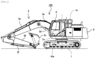
- FIG. 1 is a side view of the hydraulic excavator.
- a hydraulic excavator 100 includes a crawler-type lower track structure 1, an upper swing structure 2 provided on the lower track structure 1 in such a manner as to be swingable, and a front work implement 3 provided on a front side of the upper swing structure 2 in such a manner as to be rotatable in an up-down direction.
- the lower track structure 1, the upper swing structure 2, and the front work implement 3 (work device) together form a machine body of the hydraulic excavator 100.
- the front work implement 3 includes a plurality of to-be-driven members (a boom 3a, an arm 3b, and a bucket 3c), each of which is capable of rotating in a vertical direction, coupled to one another.
- a proximal end of the boom 3a is rotatably supported by a front portion of the upper swing structure 2.
- One end of the arm 3b is rotatably coupled to a distal end of the boom 3a, while the bucket 3c is rotatably coupled to another end (distal end) of the arm 3b.
- the boom 3a, the arm 3b, and the bucket 3c are driven by a boom cylinder 3d, an arm cylinder 3e, and a bucket cylinder 3f, respectively, which are hydraulic actuators.
- the upper swing structure 2 includes a swing frame 2a as a base portion and other members disposed thereon, and the swing frame 2a is driven by a hydraulic swing motor 5, which is a hydraulic actuator, to swing with respect to the lower track structure 1, whereby the upper swing structure 2 swings with respect to the lower track structure 1.
- a cab 4 for an operator to board to operate the hydraulic excavator 100 is disposed at the front portion of the upper swing structure 2.
- the upper swing structure 2 has installed therein other members, such as an engine as a prime mover, a hydraulic pump and a pilot pump that are driven by the engine, and a control valve that controls the flow (a direction and a flow rate) of a hydraulic operating fluid supplied from the hydraulic pump to each of the hydraulic actuators (the boom cylinder 3d, the arm cylinder 3e, the bucket cylinder 3f, the hydraulic swing motor 5, etc.).
- other members such as an engine as a prime mover, a hydraulic pump and a pilot pump that are driven by the engine, and a control valve that controls the flow (a direction and a flow rate) of a hydraulic operating fluid supplied from the hydraulic pump to each of the hydraulic actuators (the boom cylinder 3d, the arm cylinder 3e, the bucket cylinder 3f, the hydraulic swing motor 5, etc.).
- An antenna 6a is attached to an upper rear of the cab 4.
- the antenna 6a receives a radio wave (operation signal) transmitted from a transmitter (not depicted) of a wireless operation device at a remote location.
- the hydraulic excavator 100 is boardable and capable of being remotely operated, and can be operated by a remote operator as well as by an operator (on-board operator) on board the cab 4.
- FIG. 2 is a perspective view of an inside of the cab 4.
- the cab 4 includes a front surface portion 41 (depicted in FIG. 3 ), a rear surface portion 42, a left side portion 43, a right side portion 44, a ceiling 7 as an upper surface portion, and a bottom surface portion 45.
- the left side portion 43 of the cab 4 includes an entry/exit opening formed therein, and a door 43a (depicted in FIG. 1 ) capable of being opened and closed is provided in the entry/exit opening.
- Each of the front surface portion 41, the rear surface portion 42, the left side portion 43, and the right side portion 44 is partially paned to enable the on-board operator to recognize a situation of surroundings of the machine body.
- a seat 4a in which the on-board operator is to sit, operation levers 4b to 4e for driving operation of the front work implement 3, swinging operation of the upper swing structure 2, and travelling operation of the lower track structure 1, and so on are disposed in the cab 4.
- a remote communication receiver 6b is attached to a left side surface in the cab 4.
- the remote communication receiver 6b transmits an operation signal received by the antenna 6a to a first controller 10, which will be described below.
- the antenna 6a and the remote communication receiver 6b together form a remote communication device 6.
- a forward portion of the ceiling 7 of the cab 4 forms an overhead window 7a capable of being opened and closed.
- a portion of the ceiling 7 rearward of the overhead window 7a is covered with a ceiling cover 8.
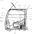
- FIG. 3 is a side sectional view of the cab 4.
- the first controller 10 and a second controller 11 are disposed in a ceiling space 9 defined between the ceiling 7 and the ceiling cover 8.
- the controllers 10 and 11 in the present embodiment have functions that enable remote operation or automatic operation of the hydraulic excavator 100.
- the first controller 10 determines an operation of the machine body on the basis of information acquired from various types of sensors and the remote communication device 6 connected thereto for functionality expansion.
- the second controller 11 generates signals (operation commands) for causing the machine body to perform the operation of the machine body determined by the first controller 10, and outputs the generated signals to components (the hydraulic pump, a solenoid valve, and a monitor) installed in the machine body.
- the second controller 11 may alternatively output the operation commands through a controller (not depicted) that is installed in a conventional standard machine, instead of outputting the operation commands directly to the installed components.
- the controllers 10 and 11 are positioned on a rear side in the cab 4, away from the overhead window 7a, and thus do not hinder opening and closing of the overhead window 7a. In addition, the controllers 10 and 11 are not exposed to rainwater even when a rainfall occurs with the overhead window 7a being open.
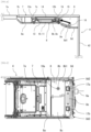
- FIG. 4 is a side sectional view of a part in the vicinity of the ceiling 7 of the cab 4.
- the ceiling cover 8, which covers a rear portion of the ceiling 7, includes a front cover 8a that covers a part behind the overhead window 7a, a left cover 8b that covers a left-hand part behind the front cover 8a, a right cover 8c that covers a right-hand part behind the front cover 8a, a rear cover 8d that covers a part behind the left cover 8b and the right cover 8c, and a connector cover 8e that closes an opening portion 8d1 of the rear cover 8d.
- the front cover 8a is fitted to the seat portion 7b.
- Brackets 12a and 12b are fitted to the seat portions 7c and 7d.
- a mounting base 13 is fitted to the brackets 12a and 12b, and the controllers 10 and 11 are fitted to the mounting base 13.
- Urethane 14 for heat insulation is fitted to the ceiling 7 between the seat portion 7c and the seat portion 7d to protect the controllers 10 and 11 against heat of sunlight.
- the covers 8b and 8c are fitted to the brackets 12a and 12b.
- the controllers 10 and 11 are connected to the antenna 6a and the remote communication receiver 6b through a harness 15.
- a reduction in length of the harness 15 can be achieved by the controllers 10 and 11 being disposed in the ceiling space 9, which is positioned in the vicinity of the antenna 6a and the remote communication receiver 6b. This makes it possible to reduce influence of disturbance noise and the risk of a broken wire.
- the harness 15 has connectors 16 for expansion equipment to be connected to the controller 10 or 11. Examples of the expansion equipment include an input device designed for acquiring operation information, machine body information, or surroundings information, an output device designed for notification of the situation of the machine body or for ensuring an environment suited to unmanned operation, and so on.
- the input devices include a communication device (receiver) and sensors (a camera (imaging device), a LiDER, etc.).
- Specific examples of the output devices include an LED (a working light, a warning light), a display device, and an actuator (a servomotor, a solenoid valve). Such an actuator is used, for example, to adjust the orientation of a sensor or an LED, or adjust the direction of a camera in accordance with an instruction from a remote operator.
- the rear cover 8d includes the opening portion 8d1, which causes the connectors 16 to be exposed to the inside of the cab 4.
- the connector cover 8e is fitted to the rear cover 8d in such a manner as to close the opening portion 8d1.
- the covers 8a to 8e have structures that can be fixed by simple means, such as hooks, pins, or bolts, and can easily be removed by hand.
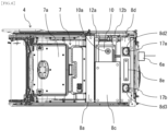
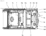
- FIG. 5 is a bottom view of the ceiling 7.
- the left cover 8b has a contour that matches the size of a casing of the first controller 10
- the right cover 8c has a contour that matches the size of a casing of the second controller 11.
- the left cover 8b includes an opening portion 8b1 which causes a reset button 10a of the first controller 10 to be exposed to the inside of the cab 4. This makes it possible to restart the first controller 10 without removing the left cover 8b.
- the rear cover 8d includes opening portions 8d2 and 8d3 which cause speakers 17a and 17b fitted to the vicinity of a rear end of the ceiling 7 to be exposed to the inside of the cab 4.
- Examples of cases where the first controller 10 needs to be restarted include (1) a case where the software of the first controller 10 has been changed (reprogrammed), (2) a case where expansion equipment has been newly added (to enable the first controller 10 to recognize the state of input from the expansion equipment for proper processing), and (3) a case where an abnormality has been recognized in behavior of the first controller 10 (to cause the first controller 10 to recover from an error condition).
- it is not necessary to remove the left cover 8b, and the ability to press the reset button 10a through the opening portion 8b1 provides a great advantage.
- the reset button 10a is disposed at a position that is rearward of an imaginary line that extends vertically upward from a headrest when a backrest of the seat 4a is in a posture adjusted for the operator to operate the machine body, that is forward of the speakers 17a and 17b in a front-rear direction of the machine body, and that is offset toward a cab door (to the left side in the present embodiment) from a middle of the inside of the cab 4 in a width direction.
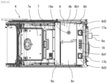
- FIG. 6 is a bottom view of the ceiling 7 with the left cover 8b (depicted in FIG. 5 ) removed.
- the first controller 10 can be exposed to the inside of the cab 4 by only the left cover 8b being removed.
- the replacement or maintenance of the first controller 10 can be accomplished in a short period of time.
- the second controller 11 can be protected by the second cover 8c.
- FIG. 7 is a bottom view of the ceiling 7 with the left cover 8b and the right cover 8c (depicted in FIG. 5 ) removed.
- the second controller 11 can be exposed to the inside of the cab 4 by the right cover 8c being removed. This makes it possible to perform replacement or maintenance of the second controller 11. Note that, because a left end portion of the right cover 8c is covered by a right end portion of the left cover 8b as illustrated in FIG. 5 , the right cover 8c cannot be removed unless the left cover 8b is removed first. This contributes to avoiding a mistaken removal of the second controller 11, which requires less frequent maintenance.
- FIG. 8 is a bottom view of the ceiling 7 with the left cover 8b, the right cover 8c, and the rear cover 8d (depicted in FIG. 5 ) removed.
- the first controller 10 and the second controller 11 are connected to the antenna 6a and the remote communication receiver 6b through the harness 15.
- the harness 15 has the connectors 16 for connecting expansion equipment to the first controller 10 or the second controller 11.
- FIG. 9 is a bottom view of the ceiling 7 with the connector cover 8e (depicted in FIG. 5 ) removed.
- the connectors 16 can be exposed to the inside of the cab 4 by the connector cover 8e being removed from the rear cover 8d of the ceiling cover 8. This makes it possible to easily connect expansion equipment to the first controller 10 or the second controller 11.
- the hydraulic excavator 100 includes the machine body 1, 2, 3 including the work device 3, the cab 4 provided in the machine body 1, 2, 3, the operation device provided in the cab 4 to operate the work device 3, the ceiling cover 8 that covers at least a portion of the ceiling in the cab 4 from below, and the first controller 10 that controls the work device 3 during remote operation or automatic operation.
- the first controller 10 includes the reset button 10a for restarting, and is disposed between the ceiling 7 and the ceiling cover 8 with the reset button 10a facing downward, and the ceiling cover 8 is fitted at such a position as to cover the first controller 10 from below, and includes the opening portion 8b1 that causes the reset button 10a to be exposed to the inside of the cab 4.
- the first controller 10 is disposed between the ceiling 7 and the ceiling cover 8 in the cab 4, allowing installation of the first controller 10 without obstructing the field of view of the on-board operator. Further, it is possible to restart the first controller 10 without removing the ceiling cover 8, by pressing the reset button 10a of the first controller 10 exposed to the inside of the cab 4 through the opening portion 8b1 of the ceiling cover 8, and it is also possible to cause the first controller 10 to be exposed to the inside of the cab 4 by removing only the first cover 8b, which makes it possible to accomplish replacement or maintenance of the first controller 10 in a short period of time.
- the opening portion 8b1 is provided below the first controller 10, which prevents rainwater, a drink, water for cleaning, or the like from falling upon the first controller 10, even when the opening portion 8b1 remains open.
- an improvement in maintenance workability is achieved because cumbersome work such as attachment/removal of the ceiling cover 8 and opening/closing of the opening portion 8b1 can be reduced.
- the first controller 10 and the head of the on-board operator can be protected by the first cover 8b because the opening portion 8b1 is only locally provided.
- the hydraulic excavator 100 further includes the second controller 11 that is connected to the first controller 10 and that outputs, on the basis of a signal inputted from the first controller 10, a command to a component installed in the machine body 1, 2, 3.
- the second controller 11 is disposed between the ceiling 7 and the ceiling cover 8, the ceiling cover 8 includes a plurality of covers 8a to 8e capable of being removed separately, the first cover 8b among the plurality of covers 8a to 8e includes the opening portion 8b1, and is fitted at such a position as to cover the first controller 10 from below without overlapping with the second controller 11 in the up-down direction, and the second cover 8c among the plurality of covers 8a to 8e is fitted at such a position as to cover the second controller 11 from below.
- the second controller 11 can be protected by the second cover 8c.
- the hydraulic excavator 100 includes the harness 15 connected to the first controller 10.
- the first controller 10 is configured to be capable of changing functionality of the machine body 1, 2, 3,
- the harness 15 has the connector 16 for connecting expansion equipment to the first controller 10, and the third cover 8e among the plurality of covers 8a to 8e is fitted at such a position as to cover the connector 16 from below.
- the expansion equipment can be connected to the first controller 10 with only the third cover 8e removed.
- a forward portion of the ceiling 7 is the overhead window 7a capable of being opened and closed, and the first cover 8b is disposed rearward of the overhead window 7a.
- This allows installation of the first controller 10 and the second controller 11 without hindering opening/closing of the overhead window 7a. Further, even in a case where a rainfall occurs with the overhead window 7a being open, the first controller 10 and the second controller 11 are not exposed to rainwater, making it possible to prevent malfunctions of the first controller 10 and the second controller 11.
Landscapes
- Engineering & Computer Science (AREA)
- Mining & Mineral Resources (AREA)
- Civil Engineering (AREA)
- General Engineering & Computer Science (AREA)
- Structural Engineering (AREA)
- Mechanical Engineering (AREA)
- Chemical & Material Sciences (AREA)
- Combustion & Propulsion (AREA)
- Transportation (AREA)
- Operation Control Of Excavators (AREA)
- Fittings On The Vehicle Exterior For Carrying Loads, And Devices For Holding Or Mounting Articles (AREA)
Abstract
Description
- The present invention relates to a construction machine, such as a hydraulic excavator.
- The technique of attaching a sensor to a machine body for sensing of a situation of surroundings of the machine body is used in a construction machine (Patent Document 1). Meanwhile, in recent years, for the purpose of enabling operation even in a situation where entry of an operator is restricted, such as in a disaster site, there has been an increasing need for unmanned operation that allows operation by remote operation or an autopilot without an operator being on board the machine body. Here, in a construction machine capable of unmanned operation, desired functions vary depending on the contents of operation, an environment of usage, etc., and thus, a controller having high expandability and allowing addition of and change in components, such as sensors, and software is used to meet a demand for a change in or adjustment of functionality. Further, replacement or maintenance (e.g., reprogramming of software, restarting, etc.) of the controller is performed with high frequency. In addition, in a case where the construction machine is configured to be capable of not only the unmanned operation but also manned operation achieved by operation by an on-board operator, the controller needs to be disposed in such a manner as not to obstruct the field of view of the on-board operator.
-
Patent Document 1 discloses a work vehicle provided with an electronic device (controller) that processes imaging data acquired by each of a first stereo camera and a second stereo camera, in which the electronic device is positioned in an inside of a cab and is attached to a ceiling of the cab, and a lower side of the electronic device is covered with an interior material cover. - Patent Document 1:
Japanese Patent No. 6831799 - However, in the work vehicle described in
Patent Document 1, it is necessary to remove the interior material cover provided at the ceiling of the cab, when performing maintenance of the controller. In a case where a structure for protecting the controller disclosed inPatent Document 1 is applied to a construction machine capable of unmanned operation, a large amount of time will be required for maintenance work because maintenance of a controller having high expandability is performed with high frequency. - The present invention has been conceived of in view of the above problem, and an object thereof is to provide a construction machine that allows a controller to be installed therein without obstructing the field of view of an on-board operator and that is able to reduce time required for maintenance of the controller.
- To achieve the above object, the present invention is directed to a construction machine including a machine body including a work device, a cab provided in the machine body, an operation device provided in the cab to operate the work device, a ceiling cover that covers at least a portion of a ceiling in the cab from below, and a first controller that controls the work device during remote operation or automatic operation, in which the first controller includes a reset button for restarting, and is disposed between the ceiling and the ceiling cover with the reset button facing downward, and the ceiling cover is fitted at such a position as to cover the first controller from below, and includes an opening portion that causes the reset button to be exposed to an inside of the cab.
- The present invention enables installation of a controller without obstructing the field of view of an on-board operator, and makes it possible to reduce time required for maintenance of the controller.
-
-
FIG. 1 is a side view of a hydraulic excavator. -
FIG. 2 is a perspective view of an inside of a cab. -
FIG. 3 is a side sectional view of the cab. -
FIG. 4 is a side sectional view of a part in the vicinity of a ceiling of the cab. -
FIG. 5 is a bottom view of the ceiling. -
FIG. 6 is a bottom view of the ceiling with a left cover removed. -
FIG. 7 is a bottom view of the ceiling with the left cover and a right cover removed. -
FIG. 8 is a bottom view of the ceiling with the left cover, the right cover, and a rear cover removed. -
FIG. 9 is a bottom view of the ceiling with a connector cover removed. - Hereinafter, an embodiment of the present invention will be described with reference to the accompanying drawings. In the drawings, same elements are designated by same reference characters, and redundant description will be omitted as appropriate. In the description of the present embodiment, a hydraulic excavator will be described as an example of a construction machine according to the present invention, but the present invention is also applicable to other construction machines, such as a dump truck, a bulldozer, and a wheel loader.
-
FIG. 1 is a side view of the hydraulic excavator. InFIG. 1 , ahydraulic excavator 100 includes a crawler-typelower track structure 1, anupper swing structure 2 provided on thelower track structure 1 in such a manner as to be swingable, and a front work implement 3 provided on a front side of theupper swing structure 2 in such a manner as to be rotatable in an up-down direction. Thelower track structure 1, theupper swing structure 2, and the front work implement 3 (work device) together form a machine body of thehydraulic excavator 100. - The
front work implement 3 includes a plurality of to-be-driven members (aboom 3a, anarm 3b, and abucket 3c), each of which is capable of rotating in a vertical direction, coupled to one another. A proximal end of theboom 3a is rotatably supported by a front portion of theupper swing structure 2. One end of thearm 3b is rotatably coupled to a distal end of theboom 3a, while thebucket 3c is rotatably coupled to another end (distal end) of thearm 3b. Theboom 3a, thearm 3b, and thebucket 3c are driven by aboom cylinder 3d, anarm cylinder 3e, and abucket cylinder 3f, respectively, which are hydraulic actuators. - The
upper swing structure 2 includes aswing frame 2a as a base portion and other members disposed thereon, and theswing frame 2a is driven by ahydraulic swing motor 5, which is a hydraulic actuator, to swing with respect to thelower track structure 1, whereby theupper swing structure 2 swings with respect to thelower track structure 1. Acab 4 for an operator to board to operate thehydraulic excavator 100 is disposed at the front portion of theupper swing structure 2. Theupper swing structure 2 has installed therein other members, such as an engine as a prime mover, a hydraulic pump and a pilot pump that are driven by the engine, and a control valve that controls the flow (a direction and a flow rate) of a hydraulic operating fluid supplied from the hydraulic pump to each of the hydraulic actuators (theboom cylinder 3d, thearm cylinder 3e, thebucket cylinder 3f, thehydraulic swing motor 5, etc.). - An
antenna 6a is attached to an upper rear of thecab 4. Theantenna 6a receives a radio wave (operation signal) transmitted from a transmitter (not depicted) of a wireless operation device at a remote location. In the present embodiment, thehydraulic excavator 100 is boardable and capable of being remotely operated, and can be operated by a remote operator as well as by an operator (on-board operator) on board thecab 4. -
FIG. 2 is a perspective view of an inside of thecab 4. Thecab 4 includes a front surface portion 41 (depicted inFIG. 3 ), arear surface portion 42, aleft side portion 43, aright side portion 44, aceiling 7 as an upper surface portion, and abottom surface portion 45. Theleft side portion 43 of thecab 4 includes an entry/exit opening formed therein, and adoor 43a (depicted inFIG. 1 ) capable of being opened and closed is provided in the entry/exit opening. Each of thefront surface portion 41, therear surface portion 42, theleft side portion 43, and theright side portion 44 is partially paned to enable the on-board operator to recognize a situation of surroundings of the machine body. Aseat 4a in which the on-board operator is to sit, operation levers 4b to 4e for driving operation of the front work implement 3, swinging operation of theupper swing structure 2, and travelling operation of thelower track structure 1, and so on are disposed in thecab 4. Aremote communication receiver 6b is attached to a left side surface in thecab 4. Theremote communication receiver 6b transmits an operation signal received by theantenna 6a to afirst controller 10, which will be described below. Theantenna 6a and theremote communication receiver 6b together form a remote communication device 6. A forward portion of theceiling 7 of thecab 4 forms anoverhead window 7a capable of being opened and closed. A portion of theceiling 7 rearward of theoverhead window 7a is covered with aceiling cover 8. -
FIG. 3 is a side sectional view of thecab 4. Thefirst controller 10 and asecond controller 11 are disposed in aceiling space 9 defined between theceiling 7 and theceiling cover 8. Thecontrollers hydraulic excavator 100. Thefirst controller 10 determines an operation of the machine body on the basis of information acquired from various types of sensors and the remote communication device 6 connected thereto for functionality expansion. Thesecond controller 11 generates signals (operation commands) for causing the machine body to perform the operation of the machine body determined by thefirst controller 10, and outputs the generated signals to components (the hydraulic pump, a solenoid valve, and a monitor) installed in the machine body. Note that thesecond controller 11 may alternatively output the operation commands through a controller (not depicted) that is installed in a conventional standard machine, instead of outputting the operation commands directly to the installed components. Thecontrollers cab 4, away from theoverhead window 7a, and thus do not hinder opening and closing of theoverhead window 7a. In addition, thecontrollers overhead window 7a being open. -
FIG. 4 is a side sectional view of a part in the vicinity of theceiling 7 of thecab 4. Theceiling cover 8, which covers a rear portion of theceiling 7, includes afront cover 8a that covers a part behind theoverhead window 7a, aleft cover 8b that covers a left-hand part behind thefront cover 8a, aright cover 8c that covers a right-hand part behind thefront cover 8a, arear cover 8d that covers a part behind theleft cover 8b and theright cover 8c, and aconnector cover 8e that closes an opening portion 8d1 of therear cover 8d. -
Seat portions ceiling 7. Thefront cover 8a is fitted to theseat portion 7b.Brackets seat portions brackets controllers Urethane 14 for heat insulation is fitted to theceiling 7 between theseat portion 7c and theseat portion 7d to protect thecontrollers covers brackets - The
controllers antenna 6a and theremote communication receiver 6b through aharness 15. A reduction in length of theharness 15 can be achieved by thecontrollers ceiling space 9, which is positioned in the vicinity of theantenna 6a and theremote communication receiver 6b. This makes it possible to reduce influence of disturbance noise and the risk of a broken wire. Theharness 15 hasconnectors 16 for expansion equipment to be connected to thecontroller rear cover 8d includes the opening portion 8d1, which causes theconnectors 16 to be exposed to the inside of thecab 4. Theconnector cover 8e is fitted to therear cover 8d in such a manner as to close the opening portion 8d1. Thecovers 8a to 8e have structures that can be fixed by simple means, such as hooks, pins, or bolts, and can easily be removed by hand. -
FIG. 5 is a bottom view of theceiling 7. Theleft cover 8b has a contour that matches the size of a casing of thefirst controller 10, and theright cover 8c has a contour that matches the size of a casing of thesecond controller 11. When replacement or maintenance (e.g., reprogramming of software) of only one of the controllers is performed, it is sufficient if only the corresponding cover is removed. Reprogramming of software of thecontroller 10 or/and thecontroller 11 is performed with a dedicated cable/cables connected to thecontroller 10 or/and thecontroller 11 exposed to the inside of thecab 4. Thus, the replacement or maintenance of thecontroller 10 or/and thecontroller 11 can be accomplished in a short period of time. Theleft cover 8b includes an opening portion 8b1 which causes areset button 10a of thefirst controller 10 to be exposed to the inside of thecab 4. This makes it possible to restart thefirst controller 10 without removing theleft cover 8b. Therear cover 8d includes opening portions 8d2 and 8d3 which causespeakers ceiling 7 to be exposed to the inside of thecab 4. - Examples of cases where the
first controller 10 needs to be restarted include (1) a case where the software of thefirst controller 10 has been changed (reprogrammed), (2) a case where expansion equipment has been newly added (to enable thefirst controller 10 to recognize the state of input from the expansion equipment for proper processing), and (3) a case where an abnormality has been recognized in behavior of the first controller 10 (to cause thefirst controller 10 to recover from an error condition). In particular, in the above case (3), it is not necessary to remove theleft cover 8b, and the ability to press thereset button 10a through the opening portion 8b1 provides a great advantage. Meanwhile, in the above case (1) or (2), work is performed with theleft cover 8b removed, but in a case where theleft cover 8b has been fitted again without thereset button 10a being pressed after the work has been performed, it is possible to press thereset button 10a without removing theleft cover 8b again, which leads to preventing an increase in the number of maintenance steps. - The
reset button 10a is disposed at a position that is rearward of an imaginary line that extends vertically upward from a headrest when a backrest of theseat 4a is in a posture adjusted for the operator to operate the machine body, that is forward of thespeakers cab 4 in a width direction. This contributes to preventing a head of an operator from touching thereset button 10a to cause an erroneous operation thereof at the time of getting on or off, and leads to improved operability of thereset button 10a when compared to a case where thereset button 10a is disposed, for example, at a rear right corner in thecab 4. -
FIG. 6 is a bottom view of theceiling 7 with theleft cover 8b (depicted inFIG. 5 ) removed. Thefirst controller 10 can be exposed to the inside of thecab 4 by only theleft cover 8b being removed. Thus, the replacement or maintenance of thefirst controller 10 can be accomplished in a short period of time. In addition, when the replacement or maintenance of thefirst controller 10 is performed with theleft cover 8b removed, thesecond controller 11 can be protected by thesecond cover 8c. -
FIG. 7 is a bottom view of theceiling 7 with theleft cover 8b and theright cover 8c (depicted inFIG. 5 ) removed. Thesecond controller 11 can be exposed to the inside of thecab 4 by theright cover 8c being removed. This makes it possible to perform replacement or maintenance of thesecond controller 11. Note that, because a left end portion of theright cover 8c is covered by a right end portion of theleft cover 8b as illustrated inFIG. 5 , theright cover 8c cannot be removed unless theleft cover 8b is removed first. This contributes to avoiding a mistaken removal of thesecond controller 11, which requires less frequent maintenance. -
FIG. 8 is a bottom view of theceiling 7 with theleft cover 8b, theright cover 8c, and therear cover 8d (depicted inFIG. 5 ) removed. Thefirst controller 10 and thesecond controller 11 are connected to theantenna 6a and theremote communication receiver 6b through theharness 15. Theharness 15 has theconnectors 16 for connecting expansion equipment to thefirst controller 10 or thesecond controller 11. -
FIG. 9 is a bottom view of theceiling 7 with theconnector cover 8e (depicted inFIG. 5 ) removed. Theconnectors 16 can be exposed to the inside of thecab 4 by theconnector cover 8e being removed from therear cover 8d of theceiling cover 8. This makes it possible to easily connect expansion equipment to thefirst controller 10 or thesecond controller 11. - In the present embodiment, the
hydraulic excavator 100 includes themachine body work device 3, thecab 4 provided in themachine body cab 4 to operate thework device 3, theceiling cover 8 that covers at least a portion of the ceiling in thecab 4 from below, and thefirst controller 10 that controls thework device 3 during remote operation or automatic operation. Thefirst controller 10 includes thereset button 10a for restarting, and is disposed between theceiling 7 and theceiling cover 8 with thereset button 10a facing downward, and theceiling cover 8 is fitted at such a position as to cover thefirst controller 10 from below, and includes the opening portion 8b1 that causes thereset button 10a to be exposed to the inside of thecab 4. - According to the present embodiment having the above configuration, the
first controller 10 is disposed between theceiling 7 and theceiling cover 8 in thecab 4, allowing installation of thefirst controller 10 without obstructing the field of view of the on-board operator. Further, it is possible to restart thefirst controller 10 without removing theceiling cover 8, by pressing thereset button 10a of thefirst controller 10 exposed to the inside of thecab 4 through the opening portion 8b1 of theceiling cover 8, and it is also possible to cause thefirst controller 10 to be exposed to the inside of thecab 4 by removing only thefirst cover 8b, which makes it possible to accomplish replacement or maintenance of thefirst controller 10 in a short period of time. Moreover, the opening portion 8b1 is provided below thefirst controller 10, which prevents rainwater, a drink, water for cleaning, or the like from falling upon thefirst controller 10, even when the opening portion 8b1 remains open. In addition, an improvement in maintenance workability is achieved because cumbersome work such as attachment/removal of theceiling cover 8 and opening/closing of the opening portion 8b1 can be reduced. Furthermore, thefirst controller 10 and the head of the on-board operator can be protected by thefirst cover 8b because the opening portion 8b1 is only locally provided. - Also, in the present embodiment, the
hydraulic excavator 100 further includes thesecond controller 11 that is connected to thefirst controller 10 and that outputs, on the basis of a signal inputted from thefirst controller 10, a command to a component installed in themachine body second controller 11 is disposed between theceiling 7 and theceiling cover 8, theceiling cover 8 includes a plurality ofcovers 8a to 8e capable of being removed separately, thefirst cover 8b among the plurality ofcovers 8a to 8e includes the opening portion 8b1, and is fitted at such a position as to cover thefirst controller 10 from below without overlapping with thesecond controller 11 in the up-down direction, and thesecond cover 8c among the plurality ofcovers 8a to 8e is fitted at such a position as to cover thesecond controller 11 from below. Thus, even when replacement or maintenance of thefirst controller 10 is performed with thefirst cover 8b removed, thesecond controller 11 can be protected by thesecond cover 8c. - Also, in the present embodiment, the
hydraulic excavator 100 includes theharness 15 connected to thefirst controller 10. Thefirst controller 10 is configured to be capable of changing functionality of themachine body harness 15 has theconnector 16 for connecting expansion equipment to thefirst controller 10, and thethird cover 8e among the plurality ofcovers 8a to 8e is fitted at such a position as to cover theconnector 16 from below. Thus, the expansion equipment can be connected to thefirst controller 10 with only thethird cover 8e removed. - Also, in the present embodiment, a forward portion of the
ceiling 7 is theoverhead window 7a capable of being opened and closed, and thefirst cover 8b is disposed rearward of theoverhead window 7a. This allows installation of thefirst controller 10 and thesecond controller 11 without hindering opening/closing of theoverhead window 7a. Further, even in a case where a rainfall occurs with theoverhead window 7a being open, thefirst controller 10 and thesecond controller 11 are not exposed to rainwater, making it possible to prevent malfunctions of thefirst controller 10 and thesecond controller 11. - While the embodiment of the present invention has been described in detail above, the present invention is not limited to the embodiment described above, and encompasses a variety of modifications. For example, the above-described embodiment has been described in detail to clearly describe the present invention, and the present invention is not necessarily limited to embodiments that have all the features described above.
-
- 1: Lower track structure (machine body)
- 2: Upper swing structure (machine body)
- 2a: Swing frame
- 3: Front work implement (work device, machine body)
- 3a: Boom
- 3b: Arm
- 3c: Bucket
- 3d: Boom cylinder
- 3e: Arm cylinder
- 3f: Bucket cylinder
- 4: Cab
- 4a: Seat
- 4b, 4c, 4d, 4e: Operation lever
- 5: Hydraulic swing motor
- 6: Remote communication device
- 6a: Antenna
- 6b: Remote communication receiver
- 7: Ceiling
- 7a: Overhead window
- 7b, 7c, 7d: Seat portion
- 8: Ceiling cover
- 8a: Front cover
- 8b: Left cover (first cover)
- 8b1: Opening portion
- 8c: Right cover (second cover)
- 8d: Rear cover
- 8d1, 8d2, 8d3: Opening portion
- 8e: Connector cover (third cover)
- 9: Ceiling space
- 10: First controller
- 10a: Reset button
- 11: Second controller
- 12a, 12b: Bracket
- 13: Mounting base
- 14: Urethane for heat insulation
- 15: Harness
- 16: Connector
- 17a, 17b: Speaker
- 100: Hydraulic excavator
Claims (4)
- A construction machine comprising:a machine body including a work device;a cab provided in the machine body;an operation device provided in the cab to operate the work device;a ceiling cover that covers at least a portion of a ceiling in the cab from below; anda first controller that controls the work device during remote operation or automatic operation, whereinthe first controller includes a reset button for restarting, and is disposed between the ceiling and the ceiling cover with the reset button facing downward, andthe ceiling cover is fitted at such a position as to cover the first controller from below, and includes an opening portion that causes the reset button to be exposed to an inside of the cab.
- The construction machine according to claim 1, further comprising:a second controller that is connected to the first controller and that outputs, on a basis of a signal inputted from the first controller, a command to a component installed in the machine body, whereinthe second controller is disposed between the ceiling and the ceiling cover,the ceiling cover includes a plurality of covers capable of being removed separately,a first cover among the plurality of covers includes the opening portion, and is fitted at such a position as to cover the first controller from below without overlapping with the second controller in an up-down direction, anda second cover among the plurality of covers is fitted at such a position as to cover the second controller from below.
- The construction machine according to claim 2, further comprising:a harness connected to the first controller, whereinthe first controller is configured to be capable of changing functionality of the machine body,the harness has a connector for connecting expansion equipment to the first controller, anda third cover among the plurality of covers is fitted at such a position as to cover the connector from below.
- The construction machine according to claim 1, whereina forward portion of the ceiling is an overhead window capable of being opened and closed, andthe ceiling cover is disposed rearward of the overhead window.
Applications Claiming Priority (2)
| Application Number | Priority Date | Filing Date | Title |
|---|---|---|---|
| JP2023007518 | 2023-01-20 | ||
| PCT/JP2024/001311 WO2024154785A1 (en) | 2023-01-20 | 2024-01-18 | Construction machine |
Publications (2)
| Publication Number | Publication Date |
|---|---|
| EP4567200A1 true EP4567200A1 (en) | 2025-06-11 |
| EP4567200A4 EP4567200A4 (en) | 2026-08-05 |
Family
ID=91955978
Family Applications (1)
| Application Number | Title | Priority Date | Filing Date |
|---|---|---|---|
| EP24744705.5A Pending EP4567200A4 (en) | 2023-01-20 | 2024-01-18 | CONSTRUCTION MACHINE |
Country Status (6)
| Country | Link |
|---|---|
| US (1) | US20260070616A1 (en) |
| EP (1) | EP4567200A4 (en) |
| JP (1) | JPWO2024154785A1 (en) |
| KR (1) | KR20250043540A (en) |
| CN (1) | CN119816640A (en) |
| WO (1) | WO2024154785A1 (en) |
Families Citing this family (1)
| Publication number | Priority date | Publication date | Assignee | Title |
|---|---|---|---|---|
| JP7887095B1 (en) * | 2025-03-04 | 2026-07-09 | 井関農機株式会社 | combine |
Family Cites Families (11)
| Publication number | Priority date | Publication date | Assignee | Title |
|---|---|---|---|---|
| US7121509B2 (en) * | 2001-09-29 | 2006-10-17 | Itex Wireless, Inc. | Alerting system for aircraft crew |
| JP2003187668A (en) * | 2001-12-17 | 2003-07-04 | Alps Electric Co Ltd | Push button switch |
| JP3985221B2 (en) * | 2001-12-28 | 2007-10-03 | 日立建機株式会社 | Interior equipment mounting device for cab for construction machinery |
| US7210356B2 (en) * | 2005-02-18 | 2007-05-01 | Caterpillar Inc | Physical agents directive dosimeter system |
| JP4877903B2 (en) * | 2005-07-19 | 2012-02-15 | 株式会社小松製作所 | Work vehicle |
| JP4761452B2 (en) * | 2006-02-07 | 2011-08-31 | 株式会社タカキタ | Remote control device for towed roll baler |
| JP5337465B2 (en) * | 2008-12-12 | 2013-11-06 | トヨタ紡織株式会社 | Overhead module |
| US10821910B2 (en) | 2017-03-31 | 2020-11-03 | Komatsu Ltd. | Work vehicle |
| JP7183078B2 (en) * | 2019-03-06 | 2022-12-05 | 株式会社クボタ | work vehicle |
| JP2021130926A (en) * | 2020-02-18 | 2021-09-09 | コベルコ建機株式会社 | Remote control support device for work machines and remote control support method |
| CN114648856A (en) * | 2022-02-28 | 2022-06-21 | 复旦大学 | Alarm disposal device and method for preventing left-over personnel from being damaged by environment in vehicle |
-
2024
- 2024-01-18 KR KR1020257006812A patent/KR20250043540A/en active Pending
- 2024-01-18 JP JP2024571800A patent/JPWO2024154785A1/ja active Pending
- 2024-01-18 WO PCT/JP2024/001311 patent/WO2024154785A1/en not_active Ceased
- 2024-01-18 CN CN202480003837.3A patent/CN119816640A/en active Pending
- 2024-01-18 US US19/108,763 patent/US20260070616A1/en active Pending
- 2024-01-18 EP EP24744705.5A patent/EP4567200A4/en active Pending
Also Published As
| Publication number | Publication date |
|---|---|
| CN119816640A (en) | 2025-04-11 |
| WO2024154785A1 (en) | 2024-07-25 |
| JPWO2024154785A1 (en) | 2024-07-25 |
| US20260070616A1 (en) | 2026-03-12 |
| KR20250043540A (en) | 2025-03-28 |
| EP4567200A4 (en) | 2026-08-05 |
Similar Documents
| Publication | Publication Date | Title |
|---|---|---|
| EP3767044B1 (en) | Pivot control device for pivoting-type working machine | |
| EP4012121A1 (en) | Work machine and surrounding monitoring system | |
| EP2255258B1 (en) | Carrier and backhoe control system and method | |
| JP6775602B2 (en) | Work vehicle and work vehicle control system | |
| US20260070616A1 (en) | Construction machine | |
| KR20150133118A (en) | Work vehicle | |
| CN117468520A (en) | Excavator and construction system | |
| CN114174604A (en) | Working machine | |
| US7890236B2 (en) | Automated control module for a power machine | |
| KR20210152559A (en) | working machine | |
| JP2021105334A (en) | Work vehicle, and control system for work vehicle | |
| KR102792510B1 (en) | Hydraulic excavator | |
| US11821171B2 (en) | Work machine | |
| CN112567103B (en) | Hydraulic excavator | |
| JP2019056234A (en) | Work machine | |
| EP3601683B1 (en) | Power machine with a boom, a boom actuator, an implement and a stop for preventing contact between the boom actuator and the implement | |
| EP4692465A1 (en) | Construction machine and remote-control system | |
| JP2009155815A (en) | Construction machinery | |
| JPH11117353A (en) | Automatic driving construction machinery | |
| EP4692464A1 (en) | Work machine | |
| KR20200111804A (en) | Construction machinery | |
| CN121443807A (en) | Construction machinery equipped with emergency stop switch | |
| CN119895100A (en) | Operating machinery | |
| JP2025105205A (en) | Shovel, and connector for shovel | |
| WO2024202723A1 (en) | Remote operation system for work machine and remote operation method for work machine |
Legal Events
| Date | Code | Title | Description |
|---|---|---|---|
| STAA | Information on the status of an ep patent application or granted ep patent |
Free format text: STATUS: THE INTERNATIONAL PUBLICATION HAS BEEN MADE |
|
| PUAI | Public reference made under article 153(3) epc to a published international application that has entered the european phase |
Free format text: ORIGINAL CODE: 0009012 |
|
| STAA | Information on the status of an ep patent application or granted ep patent |
Free format text: STATUS: REQUEST FOR EXAMINATION WAS MADE |
|
| 17P | Request for examination filed |
Effective date: 20250303 |
|
| AK | Designated contracting states |
Kind code of ref document: A1 Designated state(s): AL AT BE BG CH CY CZ DE DK EE ES FI FR GB GR HR HU IE IS IT LI LT LU LV MC ME MK MT NL NO PL PT RO RS SE SI SK SM TR |
|
| DAV | Request for validation of the european patent (deleted) | ||
| DAX | Request for extension of the european patent (deleted) | ||
| A4 | Supplementary search report drawn up and despatched |
Effective date: 20260630 |
|
| RIC1 | Information provided on ipc code assigned before grant |
Ipc: E02F 9/16 20060101AFI20260629BHEP Ipc: E02F 9/20 20060101ALI20260629BHEP Ipc: E02F 9/08 20060101ALI20260629BHEP Ipc: E02F 3/32 20060101ALI20260629BHEP Ipc: B62D 33/06 20060101ALI20260629BHEP |