EP4567196A1 - A construction equipment - Google Patents
A construction equipment Download PDFInfo
- Publication number
- EP4567196A1 EP4567196A1 EP23214333.9A EP23214333A EP4567196A1 EP 4567196 A1 EP4567196 A1 EP 4567196A1 EP 23214333 A EP23214333 A EP 23214333A EP 4567196 A1 EP4567196 A1 EP 4567196A1
- Authority
- EP
- European Patent Office
- Prior art keywords
- construction equipment
- hydraulic actuator
- force
- carriage
- actuator
- Prior art date
- Legal status (The legal status is an assumption and is not a legal conclusion. Google has not performed a legal analysis and makes no representation as to the accuracy of the status listed.)
- Granted
Links
Images


Classifications
-
- E—FIXED CONSTRUCTIONS
- E02—HYDRAULIC ENGINEERING; FOUNDATIONS; SOIL SHIFTING
- E02F—DREDGING; SOIL-SHIFTING
- E02F9/00—Component parts of dredgers or soil-shifting machines, not restricted to one of the kinds covered by groups E02F3/00 - E02F7/00
- E02F9/20—Drives; Control devices
- E02F9/22—Hydraulic or pneumatic drives
- E02F9/2264—Arrangements or adaptations of elements for hydraulic drives
- E02F9/2271—Actuators and supports therefor and protection therefor
-
- E—FIXED CONSTRUCTIONS
- E02—HYDRAULIC ENGINEERING; FOUNDATIONS; SOIL SHIFTING
- E02F—DREDGING; SOIL-SHIFTING
- E02F3/00—Dredgers; Soil-shifting machines
- E02F3/04—Dredgers; Soil-shifting machines mechanically-driven
- E02F3/28—Dredgers; Soil-shifting machines mechanically-driven with digging tools mounted on a dipper- or bucket-arm, i.e. there is either one arm or a pair of arms, e.g. dippers, buckets
- E02F3/30—Dredgers; Soil-shifting machines mechanically-driven with digging tools mounted on a dipper- or bucket-arm, i.e. there is either one arm or a pair of arms, e.g. dippers, buckets with a dipper-arm pivoted on a cantilever beam, i.e. boom
- E02F3/32—Dredgers; Soil-shifting machines mechanically-driven with digging tools mounted on a dipper- or bucket-arm, i.e. there is either one arm or a pair of arms, e.g. dippers, buckets with a dipper-arm pivoted on a cantilever beam, i.e. boom working downwardly and towards the machine, e.g. with backhoes
-
- E—FIXED CONSTRUCTIONS
- E02—HYDRAULIC ENGINEERING; FOUNDATIONS; SOIL SHIFTING
- E02F—DREDGING; SOIL-SHIFTING
- E02F9/00—Component parts of dredgers or soil-shifting machines, not restricted to one of the kinds covered by groups E02F3/00 - E02F7/00
- E02F9/20—Drives; Control devices
- E02F9/22—Hydraulic or pneumatic drives
- E02F9/2203—Arrangements for controlling the attitude of actuators, e.g. speed, floating function
-
- E—FIXED CONSTRUCTIONS
- E02—HYDRAULIC ENGINEERING; FOUNDATIONS; SOIL SHIFTING
- E02F—DREDGING; SOIL-SHIFTING
- E02F3/00—Dredgers; Soil-shifting machines
- E02F3/04—Dredgers; Soil-shifting machines mechanically-driven
- E02F3/28—Dredgers; Soil-shifting machines mechanically-driven with digging tools mounted on a dipper- or bucket-arm, i.e. there is either one arm or a pair of arms, e.g. dippers, buckets
- E02F3/30—Dredgers; Soil-shifting machines mechanically-driven with digging tools mounted on a dipper- or bucket-arm, i.e. there is either one arm or a pair of arms, e.g. dippers, buckets with a dipper-arm pivoted on a cantilever beam, i.e. boom
-
- E—FIXED CONSTRUCTIONS
- E02—HYDRAULIC ENGINEERING; FOUNDATIONS; SOIL SHIFTING
- E02F—DREDGING; SOIL-SHIFTING
- E02F3/00—Dredgers; Soil-shifting machines
- E02F3/04—Dredgers; Soil-shifting machines mechanically-driven
- E02F3/28—Dredgers; Soil-shifting machines mechanically-driven with digging tools mounted on a dipper- or bucket-arm, i.e. there is either one arm or a pair of arms, e.g. dippers, buckets
- E02F3/36—Component parts
-
- E—FIXED CONSTRUCTIONS
- E02—HYDRAULIC ENGINEERING; FOUNDATIONS; SOIL SHIFTING
- E02F—DREDGING; SOIL-SHIFTING
- E02F3/00—Dredgers; Soil-shifting machines
- E02F3/04—Dredgers; Soil-shifting machines mechanically-driven
- E02F3/28—Dredgers; Soil-shifting machines mechanically-driven with digging tools mounted on a dipper- or bucket-arm, i.e. there is either one arm or a pair of arms, e.g. dippers, buckets
- E02F3/36—Component parts
- E02F3/38—Cantilever beams, i.e. booms;, e.g. manufacturing processes, forms, geometry or materials used for booms; Dipper-arms, e.g. manufacturing processes, forms, geometry or materials used for dipper-arms; Bucket-arms
-
- E—FIXED CONSTRUCTIONS
- E02—HYDRAULIC ENGINEERING; FOUNDATIONS; SOIL SHIFTING
- E02F—DREDGING; SOIL-SHIFTING
- E02F3/00—Dredgers; Soil-shifting machines
- E02F3/04—Dredgers; Soil-shifting machines mechanically-driven
- E02F3/28—Dredgers; Soil-shifting machines mechanically-driven with digging tools mounted on a dipper- or bucket-arm, i.e. there is either one arm or a pair of arms, e.g. dippers, buckets
- E02F3/36—Component parts
- E02F3/42—Drives for dippers, buckets, dipper-arms or bucket-arms
-
- E—FIXED CONSTRUCTIONS
- E02—HYDRAULIC ENGINEERING; FOUNDATIONS; SOIL SHIFTING
- E02F—DREDGING; SOIL-SHIFTING
- E02F3/00—Dredgers; Soil-shifting machines
- E02F3/04—Dredgers; Soil-shifting machines mechanically-driven
- E02F3/28—Dredgers; Soil-shifting machines mechanically-driven with digging tools mounted on a dipper- or bucket-arm, i.e. there is either one arm or a pair of arms, e.g. dippers, buckets
- E02F3/36—Component parts
- E02F3/42—Drives for dippers, buckets, dipper-arms or bucket-arms
- E02F3/422—Drive systems for bucket-arms, front-end loaders, dumpers or the like
-
- E—FIXED CONSTRUCTIONS
- E02—HYDRAULIC ENGINEERING; FOUNDATIONS; SOIL SHIFTING
- E02F—DREDGING; SOIL-SHIFTING
- E02F3/00—Dredgers; Soil-shifting machines
- E02F3/04—Dredgers; Soil-shifting machines mechanically-driven
- E02F3/28—Dredgers; Soil-shifting machines mechanically-driven with digging tools mounted on a dipper- or bucket-arm, i.e. there is either one arm or a pair of arms, e.g. dippers, buckets
- E02F3/36—Component parts
- E02F3/42—Drives for dippers, buckets, dipper-arms or bucket-arms
- E02F3/425—Drive systems for dipper-arms, backhoes or the like
-
- E—FIXED CONSTRUCTIONS
- E02—HYDRAULIC ENGINEERING; FOUNDATIONS; SOIL SHIFTING
- E02F—DREDGING; SOIL-SHIFTING
- E02F3/00—Dredgers; Soil-shifting machines
- E02F3/04—Dredgers; Soil-shifting machines mechanically-driven
- E02F3/28—Dredgers; Soil-shifting machines mechanically-driven with digging tools mounted on a dipper- or bucket-arm, i.e. there is either one arm or a pair of arms, e.g. dippers, buckets
- E02F3/36—Component parts
- E02F3/42—Drives for dippers, buckets, dipper-arms or bucket-arms
- E02F3/427—Drives for dippers, buckets, dipper-arms or bucket-arms with mechanical drives
-
- E—FIXED CONSTRUCTIONS
- E02—HYDRAULIC ENGINEERING; FOUNDATIONS; SOIL SHIFTING
- E02F—DREDGING; SOIL-SHIFTING
- E02F3/00—Dredgers; Soil-shifting machines
- E02F3/04—Dredgers; Soil-shifting machines mechanically-driven
- E02F3/28—Dredgers; Soil-shifting machines mechanically-driven with digging tools mounted on a dipper- or bucket-arm, i.e. there is either one arm or a pair of arms, e.g. dippers, buckets
- E02F3/36—Component parts
- E02F3/42—Drives for dippers, buckets, dipper-arms or bucket-arms
- E02F3/43—Control of dipper or bucket position; Control of sequence of drive operations
-
- E—FIXED CONSTRUCTIONS
- E02—HYDRAULIC ENGINEERING; FOUNDATIONS; SOIL SHIFTING
- E02F—DREDGING; SOIL-SHIFTING
- E02F3/00—Dredgers; Soil-shifting machines
- E02F3/04—Dredgers; Soil-shifting machines mechanically-driven
- E02F3/28—Dredgers; Soil-shifting machines mechanically-driven with digging tools mounted on a dipper- or bucket-arm, i.e. there is either one arm or a pair of arms, e.g. dippers, buckets
- E02F3/36—Component parts
- E02F3/42—Drives for dippers, buckets, dipper-arms or bucket-arms
- E02F3/43—Control of dipper or bucket position; Control of sequence of drive operations
- E02F3/435—Control of dipper or bucket position; Control of sequence of drive operations for dipper-arms, backhoes or the like
-
- E—FIXED CONSTRUCTIONS
- E02—HYDRAULIC ENGINEERING; FOUNDATIONS; SOIL SHIFTING
- E02F—DREDGING; SOIL-SHIFTING
- E02F9/00—Component parts of dredgers or soil-shifting machines, not restricted to one of the kinds covered by groups E02F3/00 - E02F7/00
- E02F9/20—Drives; Control devices
- E02F9/202—Mechanical transmission, e.g. clutches, gears
-
- E—FIXED CONSTRUCTIONS
- E02—HYDRAULIC ENGINEERING; FOUNDATIONS; SOIL SHIFTING
- E02F—DREDGING; SOIL-SHIFTING
- E02F9/00—Component parts of dredgers or soil-shifting machines, not restricted to one of the kinds covered by groups E02F3/00 - E02F7/00
- E02F9/20—Drives; Control devices
- E02F9/2058—Electric or electro-mechanical or mechanical control devices of vehicle sub-units
- E02F9/2062—Control of propulsion units
- E02F9/207—Control of propulsion units of the type electric propulsion units, e.g. electric motors or generators
-
- E—FIXED CONSTRUCTIONS
- E02—HYDRAULIC ENGINEERING; FOUNDATIONS; SOIL SHIFTING
- E02F—DREDGING; SOIL-SHIFTING
- E02F9/00—Component parts of dredgers or soil-shifting machines, not restricted to one of the kinds covered by groups E02F3/00 - E02F7/00
- E02F9/20—Drives; Control devices
- E02F9/2058—Electric or electro-mechanical or mechanical control devices of vehicle sub-units
- E02F9/2095—Control of electric, electro-mechanical or mechanical equipment not otherwise provided for, e.g. ventilators, electro-driven fans
-
- E—FIXED CONSTRUCTIONS
- E02—HYDRAULIC ENGINEERING; FOUNDATIONS; SOIL SHIFTING
- E02F—DREDGING; SOIL-SHIFTING
- E02F9/00—Component parts of dredgers or soil-shifting machines, not restricted to one of the kinds covered by groups E02F3/00 - E02F7/00
- E02F9/20—Drives; Control devices
- E02F9/22—Hydraulic or pneumatic drives
-
- F—MECHANICAL ENGINEERING; LIGHTING; HEATING; WEAPONS; BLASTING
- F16—ENGINEERING ELEMENTS AND UNITS; GENERAL MEASURES FOR PRODUCING AND MAINTAINING EFFECTIVE FUNCTIONING OF MACHINES OR INSTALLATIONS; THERMAL INSULATION IN GENERAL
- F16H—GEARING
- F16H25/00—Gearings comprising primarily only cams, cam-followers and screw-and-nut mechanisms
- F16H25/18—Gearings comprising primarily only cams, cam-followers and screw-and-nut mechanisms for conveying or interconverting oscillating or reciprocating motions
- F16H25/20—Screw mechanisms
- F16H25/22—Screw mechanisms with balls, rollers, or similar members between the co-operating parts; Elements essential to the use of such members
- F16H25/2204—Screw mechanisms with balls, rollers, or similar members between the co-operating parts; Elements essential to the use of such members with balls
-
- F—MECHANICAL ENGINEERING; LIGHTING; HEATING; WEAPONS; BLASTING
- F16—ENGINEERING ELEMENTS AND UNITS; GENERAL MEASURES FOR PRODUCING AND MAINTAINING EFFECTIVE FUNCTIONING OF MACHINES OR INSTALLATIONS; THERMAL INSULATION IN GENERAL
- F16H—GEARING
- F16H25/00—Gearings comprising primarily only cams, cam-followers and screw-and-nut mechanisms
- F16H25/18—Gearings comprising primarily only cams, cam-followers and screw-and-nut mechanisms for conveying or interconverting oscillating or reciprocating motions
- F16H25/20—Screw mechanisms
- F16H25/22—Screw mechanisms with balls, rollers, or similar members between the co-operating parts; Elements essential to the use of such members
- F16H25/2247—Screw mechanisms with balls, rollers, or similar members between the co-operating parts; Elements essential to the use of such members with rollers
-
- H—ELECTRICITY
- H02—GENERATION; CONVERSION OR DISTRIBUTION OF ELECTRIC POWER
- H02K—DYNAMO-ELECTRIC MACHINES
- H02K41/00—Propulsion systems in which a rigid body is moved along a path due to dynamo-electric interaction between the body and a magnetic field travelling along the path
- H02K41/02—Linear motors; Sectional motors
-
- H—ELECTRICITY
- H02—GENERATION; CONVERSION OR DISTRIBUTION OF ELECTRIC POWER
- H02K—DYNAMO-ELECTRIC MACHINES
- H02K7/00—Arrangements for handling mechanical energy structurally associated with dynamo-electric machines, e.g. structural association with mechanical driving motors or auxiliary dynamo-electric machines
- H02K7/06—Means for converting reciprocating motion into rotary motion or vice versa
-
- B—PERFORMING OPERATIONS; TRANSPORTING
- B60—VEHICLES IN GENERAL
- B60Y—INDEXING SCHEME RELATING TO ASPECTS CROSS-CUTTING VEHICLE TECHNOLOGY
- B60Y2200/00—Type of vehicle
- B60Y2200/40—Special vehicles
- B60Y2200/41—Construction vehicles, e.g. graders, excavators
- B60Y2200/412—Excavators
-
- E—FIXED CONSTRUCTIONS
- E02—HYDRAULIC ENGINEERING; FOUNDATIONS; SOIL SHIFTING
- E02F—DREDGING; SOIL-SHIFTING
- E02F9/00—Component parts of dredgers or soil-shifting machines, not restricted to one of the kinds covered by groups E02F3/00 - E02F7/00
- E02F9/20—Drives; Control devices
- E02F9/2058—Electric or electro-mechanical or mechanical control devices of vehicle sub-units
- E02F9/2079—Control of mechanical transmission
-
- F—MECHANICAL ENGINEERING; LIGHTING; HEATING; WEAPONS; BLASTING
- F15—FLUID-PRESSURE ACTUATORS; HYDRAULICS OR PNEUMATICS IN GENERAL
- F15B—SYSTEMS ACTING BY MEANS OF FLUIDS IN GENERAL; FLUID-PRESSURE ACTUATORS, e.g. SERVOMOTORS; DETAILS OF FLUID-PRESSURE SYSTEMS, NOT OTHERWISE PROVIDED FOR
- F15B15/00—Fluid-actuated devices for displacing a member from one position to another; Gearing associated therewith
- F15B15/08—Characterised by the construction of the motor unit
- F15B15/088—Characterised by the construction of the motor unit the motor using combined actuation, e.g. electric and fluid actuation
-
- F—MECHANICAL ENGINEERING; LIGHTING; HEATING; WEAPONS; BLASTING
- F15—FLUID-PRESSURE ACTUATORS; HYDRAULICS OR PNEUMATICS IN GENERAL
- F15B—SYSTEMS ACTING BY MEANS OF FLUIDS IN GENERAL; FLUID-PRESSURE ACTUATORS, e.g. SERVOMOTORS; DETAILS OF FLUID-PRESSURE SYSTEMS, NOT OTHERWISE PROVIDED FOR
- F15B15/00—Fluid-actuated devices for displacing a member from one position to another; Gearing associated therewith
- F15B15/20—Other details, e.g. assembly with regulating devices
- F15B2015/206—Combined actuation, e.g. electric and fluid actuated
Definitions
- the present disclosure relates generally to construction equipment, specifically to a partly or fully electrically driven construction equipment.
- the disclosure is applicable on working machines within the fields of industrial construction machines or construction equipment, in particular excavators and articulated haulers.
- the disclosure will be mainly described with respect to an excavator, the disclosure is not restricted to this particular machine, but may also be used in other working machines such as articulated haulers, dump truck and backhoe loaders, loaders, skid steer loaders, as far as these working machines comprise at least one actuation device for driving a working element of the working machines, such as a tool, a dipper or a boom.
- EP 4036316A1 proposes to replace hydraulic cylinders of a construction equipment with electromechanical actuators and to obtain a fully electrical construction equipment.
- Each of the various electromechanical actuators may be integrated into a support element of the construction equipment, relative to which the working element is moved by the electromechanical actuators, so that the electromechanical actuators are protected from shocks.
- the size and weight of some of the electromechanical actuators, especially those operating distal working elements may induce some practical difficulties because of limited space in the associated support elements and/or because of a substantial offset weight for the construction equipment. In order to get around this problem, the size and weight of the concerned electromechanical actuators need to be restricted, which may impact significantly the performance of the construction equipment.
- a construction equipment comprises a working element, such as a terminal tool, a dipper or a boom, and at least one actuation device for operating the working element relative to a support element of the construction equipment, the at least one actuation device including:
- the first aspect of the disclosure may seek to provide a simple and efficient solution to give a satisfactory performance to a construction equipment having one or several electromechanical actuators with limited size and weight.
- a technical benefit may include taking benefits of kinematics of a carriage moved along an axis by an electromechanical actuator to add a hydraulic actuator connecting the carriage to the working element or the support element of the construction equipment.
- the hydraulic actuator When the hydraulic actuator is deactivated, the hydraulic actuator behaves as a rigid bar; when the hydraulic actuator is activated, the hydraulic actuator provides a hydraulically generated force to move the carriage relative to the working or support element to which the hydraulic actuator is connected.
- the hydraulic actuator when the hydraulic actuator is activated at the same time as the electromechanical actuator is activated, the above mentioned hydraulically generated force boosts the force coming from the electromechanical actuator, thereby allowing the size and weight of the electromechanical actuator to be minimized while operating the working element with substantial combined efforts and/or with a substantial combined stroke.
- the working element when the hydraulic actuator is activated whereas the electromechanical actuator is deactivated, the working element is operable according to some specific movements, in particular short-stroke and rapid movements, such as an earth unclogging movement or a sprinkling movement, or short-stroke and high-effort movement, such as big rock tearing out.
- the electromechanical actuator in so far as the electromechanical actuator can be limited in size and weight thanks to the hydraulic actuator added thereto, the electromechanical actuator is easier to be integrated and thus protected into the support or working element of the construction equipment and induces a limited offset weight.
- the second force boots the first force to operate the working element.
- a technical benefit may include improving the construction equipment, as explained above.
- the second force corresponds in magnitude to at least 50% of the first force.
- a technical benefit may include improving the construction equipment, as explained above.
- the electromechanical actuator when the electromechanical actuator is deactivated, the electromechanical actuator is lockable to hold in position the carriage along the first axis so as to operate the working element as a result of only the second force when the hydraulic actuator is activated.
- a technical benefit may include avoiding damage to the electromechanical actuator, as explained in detail later.
- the hydraulic actuator when the hydraulic actuator is activated, the hydraulic actuator deploys and retracts along a second axis having an inclination relative to the first axis, which changes when the electromechanical actuator is activated.
- a technical benefit may include providing a reliable and practical solution for the hydraulic actuator.
- the hydraulic actuator has a neutral configuration, in which the extent of the hydraulic actuator along the second axis is unchanged when the hydraulic actuator is deactivated, and to which the hydraulic actuator is configured to return after being activated.
- a technical benefit may include improving control of the actuation device.
- the hydraulic actuator has a first end, which is articulated on the carriage, and a second end, which is articulated on the first element.
- a technical benefit may include providing a practical and efficient arrangement of the hydraulic actuator.
- the hydraulic actuator comprises a double-acting cylinder having two chambers, which are each connected to a hydraulic system of the construction equipment and which are selectively supplied with pressurized fluid from the hydraulic system to deploy, respectively retract, the hydraulic actuator.
- a technical benefit may include providing a reliable and practice implementation for the hydraulic actuator.
- the double-acting cylinder includes a tube, in which the two chambers are arranged, and a single piston rod, which is movable relative to the tube as a result of fluid pressure in the two chambers.
- a technical benefit may include providing an efficient and cost-effective implementation for the hydraulic actuator.
- the hydraulic system comprises a fluid storage, a pump adapted to pressurize fluid sent from the fluid storage to the two chambers, and an electrovalve adapted to control fluid supply to the two chambers.
- a technical benefit may include providing an efficient and cost-effective implementation for the hydraulic system.
- the pump is a hydraulic pump driven by an electrical motor.
- a technical benefit may include providing a construction equipment that is all electrically powered, as explained in detail later.
- the at least one actuation device includes at least two actuation devices, and the hydraulic system is at least partly common for the at least two actuation devices.
- a technical benefit may include providing a cost-effective solution.
- the working element is a terminal tool including a bucket arranged at a distal end of an excavator arm of the construction equipment.
- a technical benefit may include providing an improved excavation arm.
- the working element is rotatably mounted on the support element, the actuation device being configured to operate in rotation the working element relative to the support element.
- a technical benefit may include providing a practical solution.
- the electromechanical actuator comprises an electric motor and a rod, which extends along the first axis and which transmits an output torque of the electric motor to the carriage to move the carriage along the rod with the first force.
- a technical benefit may include providing an efficient and reliable implementation for the electromechanical actuator.
- Figure 1 shows a construction equipment 1 (also referred to as a "construction machine” or “work machine”), which in some examples, as here, is an excavator.
- construction machine also referred to as a "construction machine” or "work machine”
- excavator an excavator
- the construction equipment 1 may comprise an upper frame 2, also called “platform”, and a lower frame 4 on which the upper frame 2 is mounted.
- the upper frame 2 includes a driver cab 21 and the lower frame 4 is equipped with a pair of continuous tracks 41, such as caterpillars tracks 41.
- the continuous tracks 41 may be driven by at least two electric motors (not shown), respectively one for each continuous track 41.
- the upper frame 2 may be pivotable around a vertical axis relative to the lower frame 4, the upper frame 2 being rotationally mounted on the lower frame 4.
- the construction equipment 1 may further comprise an excavator arm 6 that extends from the upper frame 2.
- the excavator arm 6 may include, successively from the upper frame 2, a boom 61, a dipper 62, also called "stitch", and a terminal tool 63.
- the terminal tool 63 is arranged at a distal end of the excavator arm 6, that is to say the end of the latter, which is opposed to the upper frame 2.
- the boom 61 may be rotatably mounted on the upper frame 2.
- the excavator arm 6 includes an articulation 64, or hinge, between the upper frame 2 and the boom 61.
- circles/rounds schematically represent hinge linkages or similar.
- the boom 61 is angle-shaped, which means that the boom 61 includes two straight segments that delimit between them an angle of approximately 120° here.
- the dipper 62 may be rotatably mounted on the boom 61.
- the excavator arm 6 includes an articulation 65, or hinge, between the boom 61 and the dipper 62.
- the terminal tool 63 may be rotatably mounted on the dipper 62.
- the excavator arm 6 includes an articulation 66, or hinge, between the dipper 62 and the terminal tool 63.
- the terminal tool 63 is advantageously removably attached to the dipper 62.
- the terminal tool 63 is a bucket for working the soil.
- the articulations 64, 65 and 66 allow rotating the boom 61, the dipper 62 and the terminal tool 63 around respective rotation axes which are parallel to the ground surface on which the construction equipment 1 lays. Accordingly, when the construction equipment 1 lays on a flat horizontal surface, these rotation axes are horizontal.
- the construction equipment includes one or several articulations, which are functionally similar to the articulations 64, 65 and 66 but whose rotation axes are not parallel to the ground surface.
- the construction equipment 1 comprises an actuation device 100 for operating the terminal tool 63 relative to the dipper 62.
- the actuation device 100 enables to move the terminal tool 63 relative to the dipper 62, here in rotation around the articulation 66.
- the actuation device 100 comprises a carriage 110 and an electromechanical actuator 120.
- the carriage 110 is guided and movable along an axis X100, here relative to the dipper 62.
- the electromechanical actuator 120 enables, when activated, to convert electrical power into a force F1 moving the carriage 110 along the axis X100, here relative to the dipper 62.
- the force F1 is oriented along the axis X100, the direction of the force F1 depending on the direction in which the carriage 110 is moved along the axis X100 by the electromechanical actuator 120, namely forward or reward along the axis X100, as schematically indicated on figure 2 .
- the carriage 110 that can also be called “sliding member" has a wide variety of possible implementations, provided the carriage is moved along the axis X100 upon activation of the electromechanical actuator 120.
- the guidance of the carriage 110 along the axis X100 which may be rudimentary, is also implemented in various possible ways, if any by dedicated guiding means (not shown) that may be provided by the dipper 62, for example through a form-fit arrangement between the carriage 110 and a complementary part of the dipper 62.
- the electromechanical actuator 120 may comprise an electric motor 121 and a rod 122.
- the electric motor 121 is fixedly carried by the dipper 62 and enables to convert electrical power into an output torque relative to the dipper 62.
- the rod 122 extends along the axis X100 and is configured to transmit the output torque of the electric motor 121 to the carriage 110 to move the carriage 110 along the rod 122 with the force F1.
- the carriage 110 may be mounted on the rod 122 and the carriage 110 and the rod 122 may be typically connected one with the other through a ball or roller screw connection, meaning that the rod 122 includes external threads in which are received a multitude of rolling elements, such as balls, and the carriage 110 is secured to a nut comprising internal threads which are complementary to the external threads of the rod 122.
- the carriage 110 and the rod 122 may form a helical link that is achieved by contact between at least two helical surfaces. For instance, this helical link is achieved by using a ball screw or roller screw mechanism using rolling elements, such as balls or rollers, to limit friction between the rod 122 and the carriage 110.
- the rod 122 which is typically rotationally coupled with an output shaft of the electric motor 121, may be fixed in position relative to the dipper 62.
- an activation of the electric motor 121 leads to a rotation of the rod 122 around the axis X100 and therefore to a displacement of the carriage 110 with the force F1, this displacement being rearward or forward, depending on rotation direction of the output shaft of the electric motor 121.
- the actuation device 100 further comprises a hydraulic actuator 130.
- the hydraulic actuator 130 connects the carriage 110 and the terminal tool 63 to each other so that, whether the hydraulic actuator 130 is activated or deactivated, the hydraulic actuator 130 moves the terminal tool 63 relative to the dipper 62 with at least partly the force F1 when the electromechanical actuator 120 is activated.
- the hydraulic actuator 130 is configured, whether the hydraulic actuator 130 is activated or deactivated, to move the terminal tool 63 and transmits to the latter at least partly the force F1 when the electromechanical actuator 120 is activated.
- the hydraulic actuator 130 enables, when activated, to convert hydraulic power into a force F2 moving the terminal tool 63 relative to the carriage 110.
- the hydraulic actuator 130 when the hydraulic actuator 130 is deactivated, the hydraulic actuator 130 behaves as a rigid bar to transmit to the terminal tool 63 at least partly the movement of the carriage 110 and at least partly the force F1 upon activation of the electromechanical actuator 120.
- the terminal tool 63 is moved relative to the carriage 110 with the force F2.
- the force F2 boosts the force F1 to operate the terminal tool 63.
- the hydraulic actuator 130 acts as a force booster for the electromechanical actuator 120.
- this boosting from the hydraulic actuator 130 may be substantial in the sense that the force F2 may correspond in magnitude to at least 50% of the force F1.
- the magnitude of force F2 may be at least 50% the magnitude of force F1, but may also be at least 100% or even 200% of the magnitude of the force F1.
- the electromechanical actuator 120 it is sufficient for the electromechanical actuator 120 to be dimensioned so that the force F1 it generates satisfies a nominal requirement covering common uses of the terminal tool 63, while the hydraulic actuator 130 can be dimensioned so that the force F2 it generates satisfies the complement necessary to the force F1 to exceed the aforementioned nominal requirement, i.e. typically during force peaks for the terminal tool 63.
- the electromechanical actuator 120 is more appropriate than the hydraulic actuator 130 for the aforementioned nominal requirement, in the sense that the electromechanical actuator 120 is faster and more efficient for the nominal type of work, while providing its F1 force with a limited but still substantial magnitude.
- the hydraulic actuator 130 as a booster for the electromechanical actuator 120, provides not speed, but additional force.
- the size and weight of the electromechanical actuator 120 can be minimized, by relying on the booster effect of the hydraulic actuator 130 when the nominal requirement is exceeded.
- activating the hydraulic actuator 130 can help to maintain the amplitude of movement of the terminal tool 63, while reducing the stroke of the electromechanical actuator 120, thus helping to size the latter more compactly and lightly.
- Minimizing the size and weight of the electromechanical actuator 120 in this way is highly advantageous, as it facilitates integration and, hence, impact protection of the electromechanical actuator 120 within the excavator arm 6, and limits the overhang resulting from the presence of the electromechanical actuator 120 on the excavator arm 6.
- the terminal tool 63 is operable as a result of only the force F2 upon activation of the hydraulic actuator 130.
- the electromechanical actuator 120 may be configured, when deactivated, to be locked to hold in position the carriage 110 along the axis X100.
- any locking arrangement that firmly immobilizes the carriage 110 along the axis X100 is feasible, such a locking arrangement of the electromechanical actuator 120 being known in the art.
- activating the hydraulic actuator 130 while the electromechanical actuator 120 is deactivated enables to operate the terminal tool 63 in movements that would be difficult for the electromechanical actuator 110 to achieve, such as a sprinkling movement, an earth unclogging movement, a movement for excavating large rocks, and so on.
- the hydraulic actuator 130 may be configured, when activated, to deploy and retract along an axis Y100.
- the force F2 is oriented along this axis Y100, the direction of the force F2 depending on the direction in which the hydraulic actuator 130 operates, i.e. deploys or retracts, as schematically indicated on figure 2 .
- the axis Y100 is distinct from the axis X100, especially in the sense that the axis Y100 has an inclination relative to the axis X100, which changes when the electromechanical actuator 120 is activated.
- the hydraulic actuator 130 may be articulated relative to the carriage 110 and the terminal tool 63.
- the hydraulic actuator 130 has a first end 130A, which is articulated on the carriage 110, and a second end 130B, which is articulated on the terminal tool 63.
- the first end 130A of the hydraulic actuator 130 may be attached to a hinge 111 of the carriage 110 and the second end 130B of the hydraulic actuator 130 may be attached to a hinge 63.1 of the terminal tool 63, as shown in figure 2 .
- This hinge 63.1 belongs here to a set of connecting rods-linkages 63.2 of the terminal tool 63, which is well known in the art and which enables to drive the main body of the terminal tool 63 in rotation around the articulation 66.
- the hydraulic actuator 130 may have a neutral configuration, for example the one that is shown on the figures. In this neutral configuration, the extents of the hydraulic actuator 130 along the axis Y100 is unchanged when the hydraulic actuator 130 is deactivated. Moreover, after being activated, the hydraulic actuator 130 is configured to return to this neutral configuration. In that way, kinematics of the actuation device 100 are precisely managed whether the hydraulic actuator is activated or deactivated.
- the hydraulic actuator 130 may comprise a double-acting cylinder 131 having two chambers 131.1 and 131.2 that are configured to be selectively supplied with a pressurized fluid, such as oil, to deploy, respectively retract, the hydraulic actuator 130.
- a pressurized fluid such as oil
- each of the chambers 131.1 and 131.2 is connected to a hydraulic system 8 of the construction equipment 1, which enables to supply the chambers with pressurized fluid.
- the double-acting cylinder 131 may include a tube 132, in which the two chambers 131.1 and 131.2 are arranged, and a single piston rod 133, which is movable relative to the tube 132 as a result of fluid pressure in the two chambers 131.1 and 131.2.
- the first end 130A and the second end 130B of the hydraulic actuator 100 belong respectively to the piston rod 133 and the tube 132, but the reverse is feasible.
- other implementation of the double-acting cylinder 131 is feasible.
- the hydraulic system 8 may comprise a fluid storage 81, a pump 82 and an electrovalve 83.
- the fluid storage 81 contains sufficient fluid to operate the hydraulic system 8 and includes for example a tank that is filled with fluid.
- the pump 82 connects the fluid storage 81 to the electrovalve 83 and enables to pressurize fluid sent from the fluid storage 81 to the chambers 131.1 and 131.2 through the electro-valve 83.
- the electrovalve 83 is configured to control fluid supply to each of the two chambers 131.1 and 131.2.
- the pressurized fluid coming from the pump 82 here sent by the electrovalve 83 to the chamber 131.1 while the fluid exhausting from the chamber 131.2 is sent by the electrovalve 83 directly to the fluid storage 81; in a second configuration of the electrovalve 83, the fluid pressurized by the pump 82 is sent by the electrovalve 83 to the chamber 131.2 while the fluid exhausting from the chamber 131.1 is sent by the electrovalve 83 directly to the fluid storage 81.
- the hydraulic system 8 is simple, reliable and robust.
- the hydraulic system 8 may be implemented in other ways.
- the pump 82 of the hydraulic system 8 may be a hydraulic pump driven by an electrical motor.
- the pump 82 may be electrically powered.
- the construction equipment 1 may be entirely electrically powered, in the sense that this construction equipment 1 does not include any thermal engine and is designed to activate by electrical primary power all the force-producing components of the construction equipment 1, such as here the motors driven the continuous tracks 41, the electromechanical actuator 120 and the pump 82.
- the construction equipment 1 may comprise, in addition to the actuation device 100, an actuation device 200, which is similar to the actuation device 100 but which is dedicated to operate the dipper 62 relative to the boom 61, here in rotation around the articulation 65, and/or an actuation device 300, which is similar to each of the actuation devices 100 and 200 but which is dedicated to operate the boom 61 relative to the upper frame 2, here in rotation around the articulation 64.
- each of the actuation devices 100, 200 and 300 enables to operate a working element of the construction equipment 1 relative to a support element of the construction equipment 1, the working element and the support element being respectively either the terminal tool 63 and the dipper 62 for the actuation device 100, or the dipper 62 and the boom 61 for the actuation device 200, or the boom 61 and the upper frame 2 for the actuation device 300.
- the respective specific features for the actuation device 100, for the actuation device 200 and for the actuation device 300 may be or not the same for the three actuation devices.
- the hydraulic actuator of the actuation device 300 has its second end that is not articulated on the boom 61 but on the upper frame 2.
- the hydraulic actuator of the actuation devices 100, 200 and 300 connects the carriage thereof to either the working element, as for the actuation devices 100 and 200, or the support element, as for the actuation device 300, so that, when the hydraulic actuator is activated, the force F2 moves the carriage relative to the working or support element to which the hydraulic actuator is connected.
- the hydraulic actuator of each actuation device 100, 200, 300 provides additional effort but also dynamism, in other words responsiveness and speed, which is very useful, for example, for unclogging the terminal toll 63, i.e. removing soil stuck thereto, thanks to the actuation device 100, and for sprinkling thanks to the actuation device 200.
- the hydraulic system 8 may be common to the three actuation devices 100, 200 and 300, especially in the sense that the single fluid storage 81 and the single pump 82 are used with three electrovalves that are respectively associated to the actuation devices 100, 200 and 300, such as the electrovalve 83 that is associated to the actuation device 100, as explained above.
- the actuation device to which it is referred to in this paper may be used to move an articulated blade of a construction equipment, which is fastened to a lower frame of the construction equipment, typically to the front of this lower frame for pushing material, such as soil, sand, snow or to stabilize the machine during excavating or lifting work.
- Example 1 A construction equipment comprising a working element such as a terminal tool, a dipper or a boom, and at least one actuation device for operating the working element relative to a support element of the construction equipment, the at least one actuation device including (i) a carriage which is guided and movable along a first axis, (ii) an electromechanical actuator which, when activated, converts electrical power into a first force moving the carriage along the first axis, and (iii) a hydraulic actuator, which connects the carriage and a first element that is either the working element or the support element so as to move the working element relative to the support element with at least partly the first force when the electromechanical actuator is activated, and which, when activated, converts hydraulic power into a second force moving the first element and the carriage relative to each other.
- a working element such as a terminal tool, a dipper or a boom
- at least one actuation device for operating the working element relative to a support element of the construction equipment
- Example 2 When the electromechanical actuator and the hydraulic actuator are both activated, the second force boots the first force to operate the working element.
- Example 3 When the electromechanical actuator and the hydraulic actuator are both activated, the second force corresponds in magnitude to at least 50% of the first force.
- Example 4 When the electromechanical actuator is deactivated, the electromechanical actuator is lockable to hold in position the carriage along the first axis so as to operate the working element as a result of only the second force when the hydraulic actuator is activated.
- Example 5 When the hydraulic actuator is activated, the hydraulic actuator deploys and retracts along a second axis having an inclination relative to the first axis, which changes when the electromechanical actuator is activated.
- Example 6 The hydraulic actuator has a neutral configuration, in which the extent of the hydraulic actuator along the second axis is unchanged when the hydraulic actuator is deactivated, and to which the hydraulic actuator is configured to return after being activated.
- Example 7 The hydraulic actuator has a first end, which is articulated on the carriage, and a second end, which is articulated on the first element.
- the hydraulic actuator comprises a double-acting cylinder having two chambers, which are each connected to a hydraulic system of the construction equipment and which are selectively supplied with pressurized fluid from the hydraulic system to deploy, respectively retract, the hydraulic actuator.
- the double-acting cylinder includes a tube, in which the two chambers are arranged, and a single piston rod , which is movable relative to the tube as a result of fluid pressure in the two chambers.
- the hydraulic system comprises a fluid storage, a pump adapted to pressurize fluid sent from the fluid storage to the two chambers, and an electrovalve adapted to control fluid supply to the two chambers.
- Example 11 The pump is a hydraulic pump driven by an electrical motor.
- Example 12 The at least one actuation device includes at least two actuation devices, and the hydraulic system is at least partly common for the at least two actuation devices.
- the working element is a terminal tool including a bucket arranged at a distal end of an excavator arm of the construction equipment.
- Example 14 The working element is rotatably mounted on the support element, the actuation device being configured to operate in rotation the working element relative to the support element.
- the electromechanical actuator comprises an electric motor and a rod, which extends along the first axis and which transmits an output torque of the electric motor to the carriage to move the carriage along the rod with the first force.
- Relative terms such as “below” or “above” or “upper” or “lower” or “horizontal” or “vertical” may be used herein to describe a relationship of one element to another element as illustrated in the Figures. It will be understood that these terms and those discussed above are intended to encompass different orientations of the device in addition to the orientation depicted in the Figures. It will be understood that when an element is referred to as being “connected” or “coupled” to another element, it can be directly connected or coupled to the other element, or intervening elements may be present. In contrast, when an element is referred to as being “directly connected” or “directly coupled” to another element, there are no intervening elements present.
Landscapes
- Engineering & Computer Science (AREA)
- Mechanical Engineering (AREA)
- General Engineering & Computer Science (AREA)
- Mining & Mineral Resources (AREA)
- Civil Engineering (AREA)
- Structural Engineering (AREA)
- Power Engineering (AREA)
- Physics & Mathematics (AREA)
- Chemical & Material Sciences (AREA)
- Combustion & Propulsion (AREA)
- Electromagnetism (AREA)
- Operation Control Of Excavators (AREA)
Abstract
Description
- The present disclosure relates generally to construction equipment, specifically to a partly or fully electrically driven construction equipment.
- The disclosure is applicable on working machines within the fields of industrial construction machines or construction equipment, in particular excavators and articulated haulers. Although the disclosure will be mainly described with respect to an excavator, the disclosure is not restricted to this particular machine, but may also be used in other working machines such as articulated haulers, dump truck and backhoe loaders, loaders, skid steer loaders, as far as these working machines comprise at least one actuation device for driving a working element of the working machines, such as a tool, a dipper or a boom.
- In recent years, there has been a clear trend towards the electrification of vehicles, and thus a move away from the use of fossil fuels that cause greenhouse gas emissions. Electric vehicles also have the advantage of being much quieter than their thermal counterparts.
- This trend is now spreading to construction machinery which, until now, has included a combustion engine driving a hydraulic pump. Gradually, internal combustion engines will be replaced by electric motors.
- Thus,
EP 4036316A1 proposes to replace hydraulic cylinders of a construction equipment with electromechanical actuators and to obtain a fully electrical construction equipment. Each of the various electromechanical actuators may be integrated into a support element of the construction equipment, relative to which the working element is moved by the electromechanical actuators, so that the electromechanical actuators are protected from shocks. However, the size and weight of some of the electromechanical actuators, especially those operating distal working elements, may induce some practical difficulties because of limited space in the associated support elements and/or because of a substantial offset weight for the construction equipment. In order to get around this problem, the size and weight of the concerned electromechanical actuators need to be restricted, which may impact significantly the performance of the construction equipment. - According to a first aspect of the disclosure, a construction equipment comprises a working element, such as a terminal tool, a dipper or a boom, and at least one actuation device for operating the working element relative to a support element of the construction equipment, the at least one actuation device including:
- a carriage which is guided and movable along a first axis,
- an electromechanical actuator which, when activated, converts electrical power into a first force moving the carriage along the first axis, and
- a hydraulic actuator, which connects the carriage and a first element that is either the working element or the support element so as to move the working element relative to the support element with at least partly the first force when the electromechanical actuator is activated, and which, when activated, converts hydraulic power into a second force moving the first element and the carriage relative to each other.
- The first aspect of the disclosure may seek to provide a simple and efficient solution to give a satisfactory performance to a construction equipment having one or several electromechanical actuators with limited size and weight. A technical benefit may include taking benefits of kinematics of a carriage moved along an axis by an electromechanical actuator to add a hydraulic actuator connecting the carriage to the working element or the support element of the construction equipment. When the hydraulic actuator is deactivated, the hydraulic actuator behaves as a rigid bar; when the hydraulic actuator is activated, the hydraulic actuator provides a hydraulically generated force to move the carriage relative to the working or support element to which the hydraulic actuator is connected. In that way, when the hydraulic actuator is activated at the same time as the electromechanical actuator is activated, the above mentioned hydraulically generated force boosts the force coming from the electromechanical actuator, thereby allowing the size and weight of the electromechanical actuator to be minimized while operating the working element with substantial combined efforts and/or with a substantial combined stroke. Furthermore, when the hydraulic actuator is activated whereas the electromechanical actuator is deactivated, the working element is operable according to some specific movements, in particular short-stroke and rapid movements, such as an earth unclogging movement or a sprinkling movement, or short-stroke and high-effort movement, such as big rock tearing out. In any case, in so far as the electromechanical actuator can be limited in size and weight thanks to the hydraulic actuator added thereto, the electromechanical actuator is easier to be integrated and thus protected into the support or working element of the construction equipment and induces a limited offset weight.
- Optionally in some examples, including in at least one preferred example, when the electromechanical actuator and the hydraulic actuator are both activated, the second force boots the first force to operate the working element. A technical benefit may include improving the construction equipment, as explained above.
- Optionally in some examples, including in at least one preferred example, when the electromechanical actuator and the hydraulic actuator are both activated, the second force corresponds in magnitude to at least 50% of the first force. A technical benefit may include improving the construction equipment, as explained above.
- Optionally in some examples, including in at least one preferred example, when the electromechanical actuator is deactivated, the electromechanical actuator is lockable to hold in position the carriage along the first axis so as to operate the working element as a result of only the second force when the hydraulic actuator is activated. A technical benefit may include avoiding damage to the electromechanical actuator, as explained in detail later.
- Optionally in some examples, including in at least one preferred example, when the hydraulic actuator is activated, the hydraulic actuator deploys and retracts along a second axis having an inclination relative to the first axis, which changes when the electromechanical actuator is activated. A technical benefit may include providing a reliable and practical solution for the hydraulic actuator.
- Optionally in some examples, including in at least one preferred example, the hydraulic actuator has a neutral configuration, in which the extent of the hydraulic actuator along the second axis is unchanged when the hydraulic actuator is deactivated, and to which the hydraulic actuator is configured to return after being activated. A technical benefit may include improving control of the actuation device.
- Optionally in some examples, including in at least one preferred example, the hydraulic actuator has a first end, which is articulated on the carriage, and a second end, which is articulated on the first element. A technical benefit may include providing a practical and efficient arrangement of the hydraulic actuator.
- Optionally in some examples, including in at least one preferred example, the hydraulic actuator comprises a double-acting cylinder having two chambers, which are each connected to a hydraulic system of the construction equipment and which are selectively supplied with pressurized fluid from the hydraulic system to deploy, respectively retract, the hydraulic actuator. A technical benefit may include providing a reliable and practice implementation for the hydraulic actuator.
- Optionally in some examples, including in at least one preferred example, the double-acting cylinder includes a tube, in which the two chambers are arranged, and a single piston rod, which is movable relative to the tube as a result of fluid pressure in the two chambers. A technical benefit may include providing an efficient and cost-effective implementation for the hydraulic actuator.
- Optionally in some examples, including in at least one preferred example, the hydraulic system comprises a fluid storage, a pump adapted to pressurize fluid sent from the fluid storage to the two chambers, and an electrovalve adapted to control fluid supply to the two chambers. A technical benefit may include providing an efficient and cost-effective implementation for the hydraulic system.
- Optionally in some examples, including in at least one preferred example, the pump is a hydraulic pump driven by an electrical motor. A technical benefit may include providing a construction equipment that is all electrically powered, as explained in detail later.
- Optionally in some examples, including in at least one preferred example, the at least one actuation device includes at least two actuation devices, and the hydraulic system is at least partly common for the at least two actuation devices. A technical benefit may include providing a cost-effective solution.
- Optionally in some examples, including in at least one preferred example, the working element is a terminal tool including a bucket arranged at a distal end of an excavator arm of the construction equipment. A technical benefit may include providing an improved excavation arm.
- Optionally in some examples, including in at least one preferred example, the working element is rotatably mounted on the support element, the actuation device being configured to operate in rotation the working element relative to the support element. A technical benefit may include providing a practical solution.
- Optionally in some examples, including in at least one preferred example, the electromechanical actuator comprises an electric motor and a rod, which extends along the first axis and which transmits an output torque of the electric motor to the carriage to move the carriage along the rod with the first force. A technical benefit may include providing an efficient and reliable implementation for the electromechanical actuator.
- The disclosed aspects, examples (including any preferred examples), and/or accompanying claims may be suitably combined with each other as would be apparent to anyone of ordinary skill in the art. Additional features and advantages are disclosed in the following description, claims, and drawings, and in part will be readily apparent therefrom to those skilled in the art or recognized by practicing the disclosure as described herein.
- Examples are described in more detail below with reference to the appended drawings.
-
FIG. 1 is a perspective view of an exemplary construction equipment, here an excavator, according to an example. -
FIG. 2 is a schematic view of a bucket of the excavator offigure 1 , according to an example. -
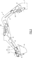
FIG. 3 is a side view of an arm of the excavator, including a boom, a dipper and the bucket, according to an example. - The detailed description set forth below provides information and examples of the disclosed technology with sufficient detail to enable those skilled in the art to practice the disclosure.
Figure 1 shows a construction equipment 1 (also referred to as a "construction machine" or "work machine"), which in some examples, as here, is an excavator. Obviously, and as mentioned above, the disclosure is not limited to this particular example as it can be applied to any other construction machine. - The construction equipment 1 may comprise an
upper frame 2, also called "platform", and alower frame 4 on which theupper frame 2 is mounted. In some examples, as the one shown in the figures, theupper frame 2 includes adriver cab 21 and thelower frame 4 is equipped with a pair ofcontinuous tracks 41, such ascaterpillars tracks 41. Thecontinuous tracks 41 may be driven by at least two electric motors (not shown), respectively one for eachcontinuous track 41. Whatever the specific features of theupper frame 2 and thelower frame 4, theupper frame 2 may be pivotable around a vertical axis relative to thelower frame 4, theupper frame 2 being rotationally mounted on thelower frame 4. - The construction equipment 1 may further comprise an
excavator arm 6 that extends from theupper frame 2. In some examples, as the one shown in the figures, theexcavator arm 6 may include, successively from theupper frame 2, aboom 61, adipper 62, also called "stitch", and aterminal tool 63. As best seen onfigure 2 , theterminal tool 63 is arranged at a distal end of theexcavator arm 6, that is to say the end of the latter, which is opposed to theupper frame 2. - As best seen on
figure 3 , theboom 61 may be rotatably mounted on theupper frame 2. For this purpose, theexcavator arm 6 includes anarticulation 64, or hinge, between theupper frame 2 and theboom 61. Onfigure 3 and onfigure 2 too, circles/rounds schematically represent hinge linkages or similar. In some examples, as the one shown in the figures, theboom 61 is angle-shaped, which means that theboom 61 includes two straight segments that delimit between them an angle of approximately 120° here. - The
dipper 62 may be rotatably mounted on theboom 61. For this purpose, theexcavator arm 6 includes anarticulation 65, or hinge, between theboom 61 and thedipper 62. - The
terminal tool 63 may be rotatably mounted on thedipper 62. For this purpose, theexcavator arm 6 includes anarticulation 66, or hinge, between thedipper 62 and theterminal tool 63. In practice, theterminal tool 63 is advantageously removably attached to thedipper 62. In the example shown in the figures, theterminal tool 63 is a bucket for working the soil. - In some examples, as the one shown in the figures, the
articulations boom 61, thedipper 62 and theterminal tool 63 around respective rotation axes which are parallel to the ground surface on which the construction equipment 1 lays. Accordingly, when the construction equipment 1 lays on a flat horizontal surface, these rotation axes are horizontal. However, in not shown variants, the construction equipment includes one or several articulations, which are functionally similar to thearticulations - As shown on the
figures 2 and3 , the construction equipment 1 comprises anactuation device 100 for operating theterminal tool 63 relative to thedipper 62. Thus, theactuation device 100 enables to move theterminal tool 63 relative to thedipper 62, here in rotation around thearticulation 66. - The
actuation device 100 comprises acarriage 110 and anelectromechanical actuator 120. Thecarriage 110 is guided and movable along an axis X100, here relative to thedipper 62. Theelectromechanical actuator 120 enables, when activated, to convert electrical power into a force F1 moving thecarriage 110 along the axis X100, here relative to thedipper 62. In practice, the force F1 is oriented along the axis X100, the direction of the force F1 depending on the direction in which thecarriage 110 is moved along the axis X100 by theelectromechanical actuator 120, namely forward or reward along the axis X100, as schematically indicated onfigure 2 . - The
carriage 110, that can also be called "sliding member", has a wide variety of possible implementations, provided the carriage is moved along the axis X100 upon activation of theelectromechanical actuator 120. The guidance of thecarriage 110 along the axis X100, which may be rudimentary, is also implemented in various possible ways, if any by dedicated guiding means (not shown) that may be provided by thedipper 62, for example through a form-fit arrangement between thecarriage 110 and a complementary part of thedipper 62. - In some examples, as the one shown in the figures, the
electromechanical actuator 120 may comprise anelectric motor 121 and arod 122. Here, theelectric motor 121 is fixedly carried by thedipper 62 and enables to convert electrical power into an output torque relative to thedipper 62. Therod 122 extends along the axis X100 and is configured to transmit the output torque of theelectric motor 121 to thecarriage 110 to move thecarriage 110 along therod 122 with the force F1. - In practice, the
carriage 110 may be mounted on therod 122 and thecarriage 110 and therod 122 may be typically connected one with the other through a ball or roller screw connection, meaning that therod 122 includes external threads in which are received a multitude of rolling elements, such as balls, and thecarriage 110 is secured to a nut comprising internal threads which are complementary to the external threads of therod 122. More generally, thecarriage 110 and therod 122 may form a helical link that is achieved by contact between at least two helical surfaces. For instance, this helical link is achieved by using a ball screw or roller screw mechanism using rolling elements, such as balls or rollers, to limit friction between therod 122 and thecarriage 110. As this type of helical connection is well known in the art, no further details are given here. In any case, therod 122, which is typically rotationally coupled with an output shaft of theelectric motor 121, may be fixed in position relative to thedipper 62. Whatever the specific features for thecarriage 110, for theelectrical motor 121 and for therod 122, an activation of theelectric motor 121 leads to a rotation of therod 122 around the axis X100 and therefore to a displacement of thecarriage 110 with the force F1, this displacement being rearward or forward, depending on rotation direction of the output shaft of theelectric motor 121. - The
actuation device 100 further comprises ahydraulic actuator 130. Thehydraulic actuator 130 connects thecarriage 110 and theterminal tool 63 to each other so that, whether thehydraulic actuator 130 is activated or deactivated, thehydraulic actuator 130 moves theterminal tool 63 relative to thedipper 62 with at least partly the force F1 when theelectromechanical actuator 120 is activated. In other words, here, thehydraulic actuator 130 is configured, whether thehydraulic actuator 130 is activated or deactivated, to move theterminal tool 63 and transmits to the latter at least partly the force F1 when theelectromechanical actuator 120 is activated. Moreover, thehydraulic actuator 130 enables, when activated, to convert hydraulic power into a force F2 moving theterminal tool 63 relative to thecarriage 110. - Thus, when the
hydraulic actuator 130 is deactivated, thehydraulic actuator 130 behaves as a rigid bar to transmit to theterminal tool 63 at least partly the movement of thecarriage 110 and at least partly the force F1 upon activation of theelectromechanical actuator 120. When thehydraulic actuator 130 is activated, theterminal tool 63 is moved relative to thecarriage 110 with the force F2. - In that way, when the
electromechanical actuator 120 and thehydraulic actuator 130 are both activated, the force F2 boosts the force F1 to operate theterminal tool 63. In other words, thehydraulic actuator 130 acts as a force booster for theelectromechanical actuator 120. In practice, this boosting from thehydraulic actuator 130 may be substantial in the sense that the force F2 may correspond in magnitude to at least 50% of the force F1. Thus, the magnitude of force F2 may be at least 50% the magnitude of force F1, but may also be at least 100% or even 200% of the magnitude of the force F1. - In any case, combining the activation of the
electromechanical actuator 120 and the activation of thehydraulic actuator 130, and thus boosting the force F1 with the force F2 have a number of advantages. In fact, when theterminal tool 63 is to be operated with a large or even very large effort, the force F2 produced by thehydraulic actuator 130 complements the force F1 produced by theelectromechanical actuator 120, thus satisfying the need for this large or even very large effort without theelectromechanical actuator 120 having to be oversized as a result. In other words, it is sufficient for theelectromechanical actuator 120 to be dimensioned so that the force F1 it generates satisfies a nominal requirement covering common uses of theterminal tool 63, while thehydraulic actuator 130 can be dimensioned so that the force F2 it generates satisfies the complement necessary to the force F1 to exceed the aforementioned nominal requirement, i.e. typically during force peaks for theterminal tool 63. In practice, theelectromechanical actuator 120 is more appropriate than thehydraulic actuator 130 for the aforementioned nominal requirement, in the sense that theelectromechanical actuator 120 is faster and more efficient for the nominal type of work, while providing its F1 force with a limited but still substantial magnitude. In this way, thehydraulic actuator 130, as a booster for theelectromechanical actuator 120, provides not speed, but additional force. As a result, the size and weight of theelectromechanical actuator 120 can be minimized, by relying on the booster effect of thehydraulic actuator 130 when the nominal requirement is exceeded. Similarly, activating thehydraulic actuator 130 can help to maintain the amplitude of movement of theterminal tool 63, while reducing the stroke of theelectromechanical actuator 120, thus helping to size the latter more compactly and lightly. Minimizing the size and weight of theelectromechanical actuator 120 in this way is highly advantageous, as it facilitates integration and, hence, impact protection of theelectromechanical actuator 120 within theexcavator arm 6, and limits the overhang resulting from the presence of theelectromechanical actuator 120 on theexcavator arm 6. These advantages are even more pronounced when theelectromechanical actuator 120 is located close to the distal end of theexcavation arm 6, as is the case for theelectromechanical actuator 120 of theactuator 100 acting on theend tool 63. - When the
hydraulic actuator 130 is activated whereas theelectromechanical actuator 120 is deactivated, theterminal tool 63 is operable as a result of only the force F2 upon activation of thehydraulic actuator 130. In that case, to avoid any damage of theelectromechanical actuator 120 due to the reaction load generated by thehydraulic actuator 130 in theactuation device 100, theelectromechanical actuator 120 may be configured, when deactivated, to be locked to hold in position thecarriage 110 along the axis X100. In practice, any locking arrangement that firmly immobilizes thecarriage 110 along the axis X100 is feasible, such a locking arrangement of theelectromechanical actuator 120 being known in the art. - In any case, activating the
hydraulic actuator 130 while theelectromechanical actuator 120 is deactivated enables to operate theterminal tool 63 in movements that would be difficult for theelectromechanical actuator 110 to achieve, such as a sprinkling movement, an earth unclogging movement, a movement for excavating large rocks, and so on. - In some examples, as the one shown in the figures, the
hydraulic actuator 130 may be configured, when activated, to deploy and retract along an axis Y100. The force F2 is oriented along this axis Y100, the direction of the force F2 depending on the direction in which thehydraulic actuator 130 operates, i.e. deploys or retracts, as schematically indicated onfigure 2 . As clearly shown byfigure 2 , the axis Y100 is distinct from the axis X100, especially in the sense that the axis Y100 has an inclination relative to the axis X100, which changes when theelectromechanical actuator 120 is activated. For this purpose, in the example shown in the figures, thehydraulic actuator 130 may be articulated relative to thecarriage 110 and theterminal tool 63. More precisely, thehydraulic actuator 130 has afirst end 130A, which is articulated on thecarriage 110, and asecond end 130B, which is articulated on theterminal tool 63. Thus, thefirst end 130A of thehydraulic actuator 130 may be attached to ahinge 111 of thecarriage 110 and thesecond end 130B of thehydraulic actuator 130 may be attached to a hinge 63.1 of theterminal tool 63, as shown infigure 2 . This hinge 63.1 belongs here to a set of connecting rods-linkages 63.2 of theterminal tool 63, which is well known in the art and which enables to drive the main body of theterminal tool 63 in rotation around thearticulation 66. - The
hydraulic actuator 130 may have a neutral configuration, for example the one that is shown on the figures. In this neutral configuration, the extents of thehydraulic actuator 130 along the axis Y100 is unchanged when thehydraulic actuator 130 is deactivated. Moreover, after being activated, thehydraulic actuator 130 is configured to return to this neutral configuration. In that way, kinematics of theactuation device 100 are precisely managed whether the hydraulic actuator is activated or deactivated. - Various implementations are possible for the
hydraulic actuator 130. In some examples, as the one shown in the figures, thehydraulic actuator 130 may comprise a double-actingcylinder 131 having two chambers 131.1 and 131.2 that are configured to be selectively supplied with a pressurized fluid, such as oil, to deploy, respectively retract, thehydraulic actuator 130. As schematically shown onfigure 2 , each of the chambers 131.1 and 131.2 is connected to a hydraulic system 8 of the construction equipment 1, which enables to supply the chambers with pressurized fluid. In that way, when the chamber 131.1 is supplied with pressurized fluid from the hydraulic system while the chamber 131.2 is not, thehydraulic actuator 130 deploys; when the chamber 131.2 is supplied with the pressurized fluid from the hydraulic system 8 while the chamber 131.1 is not, thehydraulic actuator 130 retracts. - According to a practical and efficient implementation, the double-acting
cylinder 131 may include atube 132, in which the two chambers 131.1 and 131.2 are arranged, and asingle piston rod 133, which is movable relative to thetube 132 as a result of fluid pressure in the two chambers 131.1 and 131.2. Here, thefirst end 130A and thesecond end 130B of thehydraulic actuator 100 belong respectively to thepiston rod 133 and thetube 132, but the reverse is feasible. Of course, other implementation of the double-actingcylinder 131 is feasible. - Whatever the specific features of the double-acting
cylinder 131, the hydraulic system 8 may comprise afluid storage 81, apump 82 and anelectrovalve 83. Thefluid storage 81 contains sufficient fluid to operate the hydraulic system 8 and includes for example a tank that is filled with fluid. Thepump 82 connects thefluid storage 81 to theelectrovalve 83 and enables to pressurize fluid sent from thefluid storage 81 to the chambers 131.1 and 131.2 through the electro-valve 83. Theelectrovalve 83 is configured to control fluid supply to each of the two chambers 131.1 and 131.2. In particular, in a first configuration of theelectrovalve 83, the pressurized fluid coming from thepump 82 here sent by theelectrovalve 83 to the chamber 131.1 while the fluid exhausting from the chamber 131.2 is sent by theelectrovalve 83 directly to thefluid storage 81; in a second configuration of theelectrovalve 83, the fluid pressurized by thepump 82 is sent by theelectrovalve 83 to the chamber 131.2 while the fluid exhausting from the chamber 131.1 is sent by theelectrovalve 83 directly to thefluid storage 81. Thus, the hydraulic system 8 is simple, reliable and robust. Of course, the hydraulic system 8 may be implemented in other ways. - In any case, the
pump 82 of the hydraulic system 8 may be a hydraulic pump driven by an electrical motor. In other words, thepump 82 may be electrically powered. In that way, the construction equipment 1 may be entirely electrically powered, in the sense that this construction equipment 1 does not include any thermal engine and is designed to activate by electrical primary power all the force-producing components of the construction equipment 1, such as here the motors driven thecontinuous tracks 41, theelectromechanical actuator 120 and thepump 82. - As shown on
figure 3 , the construction equipment 1 may comprise, in addition to theactuation device 100, anactuation device 200, which is similar to theactuation device 100 but which is dedicated to operate thedipper 62 relative to theboom 61, here in rotation around thearticulation 65, and/or anactuation device 300, which is similar to each of theactuation devices boom 61 relative to theupper frame 2, here in rotation around thearticulation 64. Thus, each of theactuation devices terminal tool 63 and thedipper 62 for theactuation device 100, or thedipper 62 and theboom 61 for theactuation device 200, or theboom 61 and theupper frame 2 for theactuation device 300. - In practice, the respective specific features for the
actuation device 100, for theactuation device 200 and for theactuation device 300 may be or not the same for the three actuation devices. For example, unlike theactuation device 100 whose thehydraulic actuator 130 has itssecond end 130B that is articulated on theterminal tool 63, the hydraulic actuator of theactuation device 300 has its second end that is not articulated on theboom 61 but on theupper frame 2. By the way, it is clear that more generally, the hydraulic actuator of theactuation devices actuation devices actuation device 300, so that, when the hydraulic actuator is activated, the force F2 moves the carriage relative to the working or support element to which the hydraulic actuator is connected. In any case, taking all the above into account, we see that the hydraulic actuator of eachactuation device terminal toll 63, i.e. removing soil stuck thereto, thanks to theactuation device 100, and for sprinkling thanks to theactuation device 200. - The hydraulic system 8 may be common to the three
actuation devices single fluid storage 81 and thesingle pump 82 are used with three electrovalves that are respectively associated to theactuation devices electrovalve 83 that is associated to theactuation device 100, as explained above. - According to a variant not shown, the actuation device to which it is referred to in this paper may be used to move an articulated blade of a construction equipment, which is fastened to a lower frame of the construction equipment, typically to the front of this lower frame for pushing material, such as soil, sand, snow or to stabilize the machine during excavating or lifting work.
- Example 1: A construction equipment comprising a working element such as a terminal tool, a dipper or a boom, and at least one actuation device for operating the working element relative to a support element of the construction equipment, the at least one actuation device including (i) a carriage which is guided and movable along a first axis, (ii) an electromechanical actuator which, when activated, converts electrical power into a first force moving the carriage along the first axis, and (iii) a hydraulic actuator, which connects the carriage and a first element that is either the working element or the support element so as to move the working element relative to the support element with at least partly the first force when the electromechanical actuator is activated, and which, when activated, converts hydraulic power into a second force moving the first element and the carriage relative to each other.
- Example 2: When the electromechanical actuator and the hydraulic actuator are both activated, the second force boots the first force to operate the working element.
- Example 3: When the electromechanical actuator and the hydraulic actuator are both activated, the second force corresponds in magnitude to at least 50% of the first force.
- Example 4: When the electromechanical actuator is deactivated, the electromechanical actuator is lockable to hold in position the carriage along the first axis so as to operate the working element as a result of only the second force when the hydraulic actuator is activated.
- Example 5: When the hydraulic actuator is activated, the hydraulic actuator deploys and retracts along a second axis having an inclination relative to the first axis, which changes when the electromechanical actuator is activated.
- Example 6: The hydraulic actuator has a neutral configuration, in which the extent of the hydraulic actuator along the second axis is unchanged when the hydraulic actuator is deactivated, and to which the hydraulic actuator is configured to return after being activated.
- Example 7: The hydraulic actuator has a first end, which is articulated on the carriage, and a second end, which is articulated on the first element.
- Example 8: The hydraulic actuator comprises a double-acting cylinder having two chambers, which are each connected to a hydraulic system of the construction equipment and which are selectively supplied with pressurized fluid from the hydraulic system to deploy, respectively retract, the hydraulic actuator.
- Example 9: The double-acting cylinder includes a tube, in which the two chambers are arranged, and a single piston rod , which is movable relative to the tube as a result of fluid pressure in the two chambers.
- Example 10: The hydraulic system comprises a fluid storage, a pump adapted to pressurize fluid sent from the fluid storage to the two chambers, and an electrovalve adapted to control fluid supply to the two chambers.
- Example 11: The pump is a hydraulic pump driven by an electrical motor.
- Example 12: The at least one actuation device includes at least two actuation devices, and the hydraulic system is at least partly common for the at least two actuation devices.
- Example 13: The working element is a terminal tool including a bucket arranged at a distal end of an excavator arm of the construction equipment.
- Example 14: The working element is rotatably mounted on the support element, the actuation device being configured to operate in rotation the working element relative to the support element.
- Example 15: The electromechanical actuator comprises an electric motor and a rod, which extends along the first axis and which transmits an output torque of the electric motor to the carriage to move the carriage along the rod with the first force.
- The terminology used herein is for the purpose of describing particular aspects only and is not intended to be limiting of the disclosure. As used herein, the singular forms "a," "an," and "the" are intended to include the plural forms as well, unless the context clearly indicates otherwise. As used herein, the term "and/or" includes any and all combinations of one or more of the associated listed items. It will be further understood that the terms "comprises," "comprising," "includes," and/or "including" when used herein specify the presence of stated features, integers, actions, steps, operations, elements, and/or components, but do not preclude the presence or addition of one or more other features, integers, actions, steps, operations, elements, components, and/or groups thereof.
- It will be understood that, although the terms first, second, etc., may be used herein to describe various elements, these elements should not be limited by these terms. These terms are only used to distinguish one element from another. For example, a first element could be termed a second element, and, similarly, a second element could be termed a first element without departing from the scope of the present disclosure.
- Relative terms such as "below" or "above" or "upper" or "lower" or "horizontal" or "vertical" may be used herein to describe a relationship of one element to another element as illustrated in the Figures. It will be understood that these terms and those discussed above are intended to encompass different orientations of the device in addition to the orientation depicted in the Figures. It will be understood that when an element is referred to as being "connected" or "coupled" to another element, it can be directly connected or coupled to the other element, or intervening elements may be present. In contrast, when an element is referred to as being "directly connected" or "directly coupled" to another element, there are no intervening elements present.
- Unless otherwise defined, all terms (including technical and scientific terms) used herein have the same meaning as commonly understood by one of ordinary skill in the art to which this disclosure belongs. It will be further understood that terms used herein should be interpreted as having a meaning consistent with their meaning in the context of this specification and the relevant art and will not be interpreted in an idealized or overly formal sense unless expressly so defined herein.
- It is to be understood that the present disclosure is not limited to the aspects described above and illustrated in the drawings; rather, the skilled person will recognize that many changes and modifications may be made within the scope of the present disclosure and appended claims. In the drawings and specification, there have been disclosed aspects for purposes of illustration only and not for purposes of limitation, the scope of the disclosure being set forth in the following claims.
Claims (15)
- A construction equipment (1), comprising a working element (61, 62, 63), such as a terminal tool, a dipper or a boom, and at least one actuation device (100, 200, 300) for operating the working element relative to a support element (2, 61, 62) of the construction equipment, the at least one actuation device (100) including:- a carriage (110) which is guided and movable along a first axis (X100),- an electromechanical actuator (120) which, when activated, converts electrical power into a first force (F1) moving the carriage along the first axis, and- a hydraulic actuator (130), which connects the carriage and a first element (2, 62, 63) that is either the working element or the support element so as to move the working element relative to the support element with at least partly the first force (F1) when the electromechanical actuator is activated, and which, when activated, converts hydraulic power into a second force (F2) moving the first element and the carriage relative to each other.
- The construction equipment according to claim 1, wherein when the electromechanical actuator (120) and the hydraulic actuator (130) are both activated, the second force (F2) boots the first force (F1) to operate the working element (63).
- The construction equipment according to claim 1 or 2, wherein when the electromechanical actuator (120) and the hydraulic actuator (130) are both activated, the second force (F2) corresponds in magnitude to at least 50% of the first force (F1).
- The construction equipment according to any previous claim, wherein when the electromechanical actuator (120) is deactivated, the electromechanical actuator is lockable to hold in position the carriage (110) along the first axis (X100) so as to operate the working element (63) as a result of only the second force (F2) when the hydraulic actuator is activated.
- The construction equipment according to any previous claim, wherein when the hydraulic actuator (130) is activated, the hydraulic actuator deploys and retracts along a second axis (Y100) having an inclination relative to the first axis (X100), which changes when the electromechanical actuator is activated.
- The construction equipment according to claim 5, wherein the hydraulic actuator (130) has a neutral configuration, in which the extent of the hydraulic actuator along the second axis (Y100) is unchanged when the hydraulic actuator is deactivated, and to which the hydraulic actuator is configured to return after being activated.
- The construction equipment according to any previous claim, wherein the hydraulic actuator (130) has a first end (130A), which is articulated on the carriage (110), and a second end (130B), which is articulated on the first element (63).
- The construction equipment according to any previous claim, wherein the hydraulic actuator (130) comprises a double-acting cylinder (131) having two chambers (131.1, 131.2), which are each connected to a hydraulic system (8) of the construction equipment (1) and which are selectively supplied with pressurized fluid from the hydraulic system to deploy, respectively retract, the hydraulic actuator.
- The constructing equipment according to claim 8, wherein the double-acting cylinder (131) includes a tube (132), in which the two chambers (131.1, 131.2) are arranged, and a single piston rod (133) , which is movable relative to the tube as a result of fluid pressure in the two chambers.
- The construction equipment according to claim 8 or 9, wherein the hydraulic system (8) comprises a fluid storage (81), a pump (82) adapted to pressurize fluid sent from the fluid storage to the two chambers (131.1, 131.2), and an electrovalve (83) adapted to control fluid supply to the two chambers.
- The construction equipment according to claim 10, wherein the pump is a hydraulic pump (82) driven by an electrical motor.
- The construction equipment according to any of the claims 8 to 11, wherein the at least one actuation device includes at least two actuation devices (100, 200, 300), and wherein the hydraulic system (8) is at least partly common for the at least two actuation devices.
- The construction equipment according to any previous claim, wherein the working element is a terminal tool (63) including a bucket arranged at a distal end of an excavator arm (6) of the construction equipment (1).
- The construction equipment according to any previous claim, wherein the working element (61, 62, 63) is rotatably mounted on the support element (2, 61, 62), the actuation device (100, 200, 300) being configured to operate in rotation the working element relative to the support element.
- The construction equipment according to any previous claim, wherein the electromechanical actuator (120) comprises an electric motor (121) and a rod (122), which extends along the first axis (X100) and which transmits an output torque of the electric motor to the carriage (110) to move the carriage along the rod with the first force (F1).
Priority Applications (4)
| Application Number | Priority Date | Filing Date | Title |
|---|---|---|---|
| EP23214333.9A EP4567196B1 (en) | 2023-12-05 | 2023-12-05 | A construction equipment |
| KR1020240176938A KR20250086517A (en) | 2023-12-05 | 2024-12-02 | A construction equipment |
| US18/966,789 US12460384B2 (en) | 2023-12-05 | 2024-12-03 | Construction equipment |
| CN202411757936.9A CN120100018A (en) | 2023-12-05 | 2024-12-03 | Construction equipment |
Applications Claiming Priority (1)
| Application Number | Priority Date | Filing Date | Title |
|---|---|---|---|
| EP23214333.9A EP4567196B1 (en) | 2023-12-05 | 2023-12-05 | A construction equipment |
Publications (2)
| Publication Number | Publication Date |
|---|---|
| EP4567196A1 true EP4567196A1 (en) | 2025-06-11 |
| EP4567196B1 EP4567196B1 (en) | 2026-07-22 |
Family
ID=89119543
Family Applications (1)
| Application Number | Title | Priority Date | Filing Date |
|---|---|---|---|
| EP23214333.9A Active EP4567196B1 (en) | 2023-12-05 | 2023-12-05 | A construction equipment |
Country Status (4)
| Country | Link |
|---|---|
| US (1) | US12460384B2 (en) |
| EP (1) | EP4567196B1 (en) |
| KR (1) | KR20250086517A (en) |
| CN (1) | CN120100018A (en) |
Citations (8)
| Publication number | Priority date | Publication date | Assignee | Title |
|---|---|---|---|---|
| EP0163602A2 (en) * | 1984-05-29 | 1985-12-04 | SIG Schweizerische Industrie-Gesellschaft | Arrangement for increasing the driving force of a control motor in a linear positioning drive |
| US6276223B1 (en) * | 1996-02-02 | 2001-08-21 | Sintokogio, Ltd. | Motor-operated cylinder |
| US6789335B1 (en) * | 1999-03-31 | 2004-09-14 | Kobelco Construction Machinery Co., Ltd. | Shovel |
| WO2016097784A1 (en) * | 2014-12-16 | 2016-06-23 | Volvo Construction Equipment Ab | Excavator arm, excavator cantilever member including such an excavator arm and excavator including such an excavator cantilever member |
| CN111255764A (en) * | 2020-02-18 | 2020-06-09 | 燕山大学 | Energy-saving electric servo actuator |
| EP4036316A1 (en) | 2021-02-02 | 2022-08-03 | Volvo Construction Equipment AB | Construction equipment with at least one electric actuator |
| WO2022239730A1 (en) * | 2021-05-10 | 2022-11-17 | 株式会社小松製作所 | Electric cylinder and work machine |
| US20230151830A1 (en) * | 2021-11-17 | 2023-05-18 | Taiyuan University Of Technology | Hydraulic-electric coupling driven multi-actuator system and control method |
Family Cites Families (2)
| Publication number | Priority date | Publication date | Assignee | Title |
|---|---|---|---|---|
| KR102195463B1 (en) | 2020-05-12 | 2020-12-28 | 우원개발 주식회사 | Apparatus for nonvibration rock splitting and method for excavating the same |
| KR102630277B1 (en) | 2021-10-20 | 2024-01-29 | 한국철도기술연구원 | Multi-boom wedge rock splitting system, and non-vibration rock crushing method using the same |
-
2023
- 2023-12-05 EP EP23214333.9A patent/EP4567196B1/en active Active
-
2024
- 2024-12-02 KR KR1020240176938A patent/KR20250086517A/en active Pending
- 2024-12-03 CN CN202411757936.9A patent/CN120100018A/en active Pending
- 2024-12-03 US US18/966,789 patent/US12460384B2/en active Active
Patent Citations (8)
| Publication number | Priority date | Publication date | Assignee | Title |
|---|---|---|---|---|
| EP0163602A2 (en) * | 1984-05-29 | 1985-12-04 | SIG Schweizerische Industrie-Gesellschaft | Arrangement for increasing the driving force of a control motor in a linear positioning drive |
| US6276223B1 (en) * | 1996-02-02 | 2001-08-21 | Sintokogio, Ltd. | Motor-operated cylinder |
| US6789335B1 (en) * | 1999-03-31 | 2004-09-14 | Kobelco Construction Machinery Co., Ltd. | Shovel |
| WO2016097784A1 (en) * | 2014-12-16 | 2016-06-23 | Volvo Construction Equipment Ab | Excavator arm, excavator cantilever member including such an excavator arm and excavator including such an excavator cantilever member |
| CN111255764A (en) * | 2020-02-18 | 2020-06-09 | 燕山大学 | Energy-saving electric servo actuator |
| EP4036316A1 (en) | 2021-02-02 | 2022-08-03 | Volvo Construction Equipment AB | Construction equipment with at least one electric actuator |
| WO2022239730A1 (en) * | 2021-05-10 | 2022-11-17 | 株式会社小松製作所 | Electric cylinder and work machine |
| US20230151830A1 (en) * | 2021-11-17 | 2023-05-18 | Taiyuan University Of Technology | Hydraulic-electric coupling driven multi-actuator system and control method |
Also Published As
| Publication number | Publication date |
|---|---|
| US12460384B2 (en) | 2025-11-04 |
| CN120100018A (en) | 2025-06-06 |
| KR20250086517A (en) | 2025-06-13 |
| US20250179773A1 (en) | 2025-06-05 |
| EP4567196B1 (en) | 2026-07-22 |
Similar Documents
| Publication | Publication Date | Title |
|---|---|---|
| EP3159456B1 (en) | Hydraulic hybrid circuit with energy storage for excavators or other heavy equipment | |
| US9394924B2 (en) | Hydrostatic system configured to be integrated in an excavator | |
| US9086061B2 (en) | Energy recovery hydraulic system | |
| US9845590B2 (en) | Hydraulic system for an earth moving machine | |
| US20210207344A1 (en) | Hydraulic system for increasing operation speed of construction machinery boom | |
| WO2013184539A1 (en) | Electro-hydraulic system for recovering and reusing potential energy | |
| CN102245908A (en) | Hydraulic drive for construction machine | |
| JP2004125094A (en) | Work vehicle hydraulic system | |
| US9051944B2 (en) | Hydraulic system and control logic for collection and recovery of energy in a double actuator arrangement | |
| EP4036316A1 (en) | Construction equipment with at least one electric actuator | |
| US20130081382A1 (en) | Regeneration configuration for closed-loop hydraulic systems | |
| CN113423900B (en) | Engineering machinery | |
| EP1126088B1 (en) | Hydraulic system for the dampening of inertia load | |
| US12460384B2 (en) | Construction equipment | |
| US20100156115A1 (en) | System for recovering or converting energy for equipment having a movable implement and method | |
| WO2015185182A1 (en) | Lift arm linkage for a skid steer loader | |
| AU2020102801A4 (en) | Hydraulic cylinder with specific performance dimensions | |
| AU2020102783A4 (en) | Hydraulic cylinder with specific performance dimensions | |
| AU2020102777A4 (en) | Hydraulic cylinder with specific performance dimensions | |
| AU2020102779A4 (en) | Hydraulic cylinder with specific performance dimensions | |
| AU2020102803A4 (en) | Hydraulic cylinder with specific performance dimensions | |
| CN212717454U (en) | Actuator and machine | |
| AU2020102793A4 (en) | Hydraulic cylinder with specific performance dimensions | |
| CN212717458U (en) | Actuator and machine | |
| CN212717459U (en) | Actuator and machine |
Legal Events
| Date | Code | Title | Description |
|---|---|---|---|
| PUAI | Public reference made under article 153(3) epc to a published international application that has entered the european phase |
Free format text: ORIGINAL CODE: 0009012 |
|
| STAA | Information on the status of an ep patent application or granted ep patent |
Free format text: STATUS: THE APPLICATION HAS BEEN PUBLISHED |
|
| AK | Designated contracting states |
Kind code of ref document: A1 Designated state(s): AL AT BE BG CH CY CZ DE DK EE ES FI FR GB GR HR HU IE IS IT LI LT LU LV MC ME MK MT NL NO PL PT RO RS SE SI SK SM TR |
|
| STAA | Information on the status of an ep patent application or granted ep patent |
Free format text: STATUS: REQUEST FOR EXAMINATION WAS MADE |
|
| 17P | Request for examination filed |
Effective date: 20251112 |
|
| GRAP | Despatch of communication of intention to grant a patent |
Free format text: ORIGINAL CODE: EPIDOSNIGR1 |
|
| STAA | Information on the status of an ep patent application or granted ep patent |
Free format text: STATUS: GRANT OF PATENT IS INTENDED |
|
| RIC1 | Information provided on ipc code assigned before grant |
Ipc: E02F 3/38 20060101AFI20260217BHEP Ipc: E02F 3/42 20060101ALI20260217BHEP Ipc: E02F 9/20 20060101ALI20260217BHEP Ipc: E02F 9/22 20060101ALI20260217BHEP Ipc: F15B 15/08 20060101ALI20260217BHEP Ipc: F16H 25/22 20060101ALI20260217BHEP Ipc: H02K 7/06 20060101ALI20260217BHEP Ipc: F16H 25/20 20060101ALI20260217BHEP |
|
| INTG | Intention to grant announced |
Effective date: 20260318 |
|
| GRAS | Grant fee paid |
Free format text: ORIGINAL CODE: EPIDOSNIGR3 |
|
| GRAA | (expected) grant |
Free format text: ORIGINAL CODE: 0009210 |
|
| STAA | Information on the status of an ep patent application or granted ep patent |
Free format text: STATUS: THE PATENT HAS BEEN GRANTED |
|
| AK | Designated contracting states |
Kind code of ref document: B1 Designated state(s): AL AT BE BG CH CY CZ DE DK EE ES FI FR GB GR HR HU IE IS IT LI LT LU LV MC ME MK MT NL NO PL PT RO RS SE SI SK SM TR |
|
| REG | Reference to a national code |
Ref country code: CH Ref legal event code: F10 Free format text: ST27 STATUS EVENT CODE: U-0-0-F10-F00 (AS PROVIDED BY THE NATIONAL OFFICE) Effective date: 20260722 Ref country code: GB Ref legal event code: FG4D |
|
| REG | Reference to a national code |
Ref country code: IE Ref legal event code: FG4D |
|
| REG | Reference to a national code |
Ref country code: DE Ref legal event code: R096 Ref document number: 602023020171 Country of ref document: DE |