EP4567173A1 - Tensioning device for air jet loom - Google Patents
Tensioning device for air jet loom Download PDFInfo
- Publication number
- EP4567173A1 EP4567173A1 EP24212901.3A EP24212901A EP4567173A1 EP 4567173 A1 EP4567173 A1 EP 4567173A1 EP 24212901 A EP24212901 A EP 24212901A EP 4567173 A1 EP4567173 A1 EP 4567173A1
- Authority
- EP
- European Patent Office
- Prior art keywords
- protrusion
- weft yarn
- passage
- air
- reed
- Prior art date
- Legal status (The legal status is an assumption and is not a legal conclusion. Google has not performed a legal analysis and makes no representation as to the accuracy of the status listed.)
- Granted
Links
Images



Classifications
-
- D—TEXTILES; PAPER
- D03—WEAVING
- D03D—WOVEN FABRICS; METHODS OF WEAVING; LOOMS
- D03D47/00—Looms in which bulk supply of weft does not pass through shed, e.g. shuttleless looms, gripper shuttle looms, dummy shuttle looms
- D03D47/28—Looms in which bulk supply of weft does not pass through shed, e.g. shuttleless looms, gripper shuttle looms, dummy shuttle looms wherein the weft itself is projected into the shed
- D03D47/30—Looms in which bulk supply of weft does not pass through shed, e.g. shuttleless looms, gripper shuttle looms, dummy shuttle looms wherein the weft itself is projected into the shed by gas jet
- D03D47/3066—Control or handling of the weft at or after arrival
- D03D47/308—Stretching or holding the weft
-
- D—TEXTILES; PAPER
- D03—WEAVING
- D03D—WOVEN FABRICS; METHODS OF WEAVING; LOOMS
- D03D47/00—Looms in which bulk supply of weft does not pass through shed, e.g. shuttleless looms, gripper shuttle looms, dummy shuttle looms
- D03D47/28—Looms in which bulk supply of weft does not pass through shed, e.g. shuttleless looms, gripper shuttle looms, dummy shuttle looms wherein the weft itself is projected into the shed
- D03D47/30—Looms in which bulk supply of weft does not pass through shed, e.g. shuttleless looms, gripper shuttle looms, dummy shuttle looms wherein the weft itself is projected into the shed by gas jet
- D03D47/3066—Control or handling of the weft at or after arrival
-
- D—TEXTILES; PAPER
- D03—WEAVING
- D03D—WOVEN FABRICS; METHODS OF WEAVING; LOOMS
- D03D49/00—Details or constructional features not specially adapted for looms of a particular type
- D03D49/60—Construction or operation of slay
-
- D—TEXTILES; PAPER
- D03—WEAVING
- D03J—AUXILIARY WEAVING APPARATUS; WEAVERS' TOOLS; SHUTTLES
- D03J1/00—Auxiliary apparatus combined with or associated with looms
- D03J1/002—Climatic conditioning or removing lint or dust
Definitions
- the present invention relates to a tensioning device for an air jet loom.
- an air jet loom has a reed formed of a plurality of reed dents arranged in a weft insertion direction and inserts a weft yarn along a weft yarn guide passage provided in the reed.
- the reed dents are arranged at regular intervals in the weft insertion direction.
- a gap is formed between the reed dents arranged side by side.
- a warp yarn passes through each gap located within a weaving width.
- the air jet loom has a tensioning device that tensions the inserted weft yarn.
- the tensioning device tensions the weft yarn traveling through the weft yarn guide passage to prevent the weft yarn from becoming loose. This contributes to weaving of high-quality fabric.
- a weft yarn tensioning device described in Japanese Patent Application Publication No. 2022-014545 includes an upper stretch mechanism portion corresponding to a passage defining portion by which a weft yarn traveling passage is formed and a lower stretch mechanism portion in which a stretch air passage is formed.
- An air release hole is opened in an upper surface of the weft yarn traveling passage of the upper stretch mechanism portion, and serves as an air exhaust port.
- the weft yarn tensioning device described in the Publication includes an air blow nozzle having an air blow injection port and a stretch air injection port from which air is injected in a direction different from a direction along the weft yarn traveling passage.
- the air blow nozzle injects air in the direction along the weft yarn traveling passage.
- the injected air introduces the weft yarn into the weft yarn traveling passage and tensions the weft yarn.
- Air supplied through the stretch air passage is injected from the stretch air injection port toward the weft yarn introduced into the weft yarn traveling passage.
- the air injected from the stretch air injection port tensions the weft yarn in the weft yarn traveling passage, and then, is exhausted outside the upper stretch mechanism portion through the air release hole. After the air is exhausted through the air release hole, the air passes through a gap located above the air release hole.
- Fluff generated during the weaving may pass through the weft yarn traveling passage, and then, may be discharged outside the upper stretch mechanism portion together with the air exhausted through the air release hole.
- the fluff discharged outside the upper stretch mechanism portion may pile up in the gap located above the air release hole.
- a tensioning device for an air jet loom that inserts a weft yarn along a weft yarn guide passage formed in a reed, the reed being formed of a plurality of reed dents that are arranged side by side with gaps in a weft insertion direction in which the weft yarn is inserted.
- the tensioning device includes a passage defining portion that defines a weft yarn traveling passage extending along the weft yarn guide passage.
- the passage defining portion has an upper surface facing an upper wall of the reed, the upper wall partially defining the weft yarn guide passage, and an air exhaust port being opened in the upper surface and communicating with the weft yarn traveling passage.
- the air exhaust port faces at least one of the gaps.
- the tensioning device is configured to tension the weft yarn by injecting air into the weft yarn traveling passage, the air being discharged through the air exhaust port.
- the passage defining portion has a protrusion that comes in contact with at least one of adjacent two of the reed dents such that the protrusion widens one of the gaps facing the air exhaust port and defined by the two adjacent reed dents.
- an air jet loom 100 includes a main nozzle M, a sub nozzle S, a reed 10, a sley 20, and a tensioning device 30.
- a weft yarn guide passage 10a through which a weft yarn Y travels is formed in the reed 10.
- a direction in which the weft yarn guide passage 10a extends coincides with a longitudinal direction of the sley 20.
- the weft yarn Y is inserted from the main nozzle M into the weft yarn guide passage 10a. That is, the air jet loom 100 inserts the weft yarn Y along the weft yarn guide passage 10a formed in the reed 10.
- the weft yarn Y travels in the longitudinal direction of the sley 20.
- a direction in which the weft yarn Y travels is referred to as a weft insertion direction W.
- a side in the weft insertion direction W on which the main nozzle M is located is referred to as an "upstream” side
- a side in the weft insertion direction W opposite to the upstream side is referred to as a "downstream” side.
- the weft yarn Y is beaten by the reed 10 after being inserted.
- a direction in which the reed 10 moves during the beating is referred to as a front-rear direction FB.
- the front-rear direction FB is orthogonal to the weft insertion direction W.
- a direction orthogonal to each of the weft insertion direction W and the front-rear direction FB is referred to as an up-down direction UD.
- the up-down direction UD coincides with a vertical direction.
- the reed 10 and the weft yarn Y are arranged in the front-rear direction FB.
- the air jet loom 100 weaves fabric C. Aside in the front-rear direction FB on which the woven fabric C is wound is referred to as a "front" side, and a side in the front-rear direction FB opposite to the front side is referred to as a "rear" side.
- the main nozzle M is provided on the sley 20.
- the main nozzle M is fixed to the sley 20 and located on the upstream side in the weft insertion direction W.
- the weft yarn Y is inserted from the main nozzle M into the weft yarn guide passage 10a.
- the main nozzle M is attached to the sley 20 so that its position is adjustable in the weft insertion direction W.
- the sub nozzle S is fixed to the sley 20. Air is injected from the sub nozzle S into the weft yarn guide passage 10a. A direction in which air is injected from the sub nozzle S is along the weft insertion direction W. Then, the weft yarn Y travels in the weft insertion direction W through the weft yarn guide passage 10a by the air injection from the main nozzle M and the sub nozzle S.
- the reed 10 has a plurality of the reed dents 11 and a holding member 12.
- the holding member 12 holds the plurality of the reed dents 11.
- the plurality of the reed dents 11 are arranged in a line in the weft insertion direction W of the weft yarn Y. That is, in the air jet loom 100, the plurality of the reed dents 11 are arranged side by side in the weft insertion direction W of the weft yarn Y.
- a gap 10b is defined by any adjacent two of the reed dents 11 in the weft insertion direction W therebetween. In other words, in the reed 10, the gaps 10b are defined by the reed dents 11 arranged side by side. In the reed 10, a plurality of the gaps 10b are formed.
- a warp yarn T passes through each of the gap 10b. However, the warp yarn T does not pass through each of the gaps 10b located at a position where the tensioning device 30, which will be described later, is provided. In the reed 10, the intervals of the gaps 10b are constant excluding the gap 10b into which a protrusion 50 illustrated in FIG. 2 is inserted.
- each of the reed dents 11 has a recess 13.
- the reed dents 11 are each recessed from its front surface toward its rear surface to form the recess 13.
- the reed dents 11 each have a rear side edge 13a, an upper side edge 13b, and a lower side edge 13c.
- the recess 13 is defined by the rear side edge 13a, the upper side edge 13b, and the lower side edge 13c.
- the rear side edge 13a is located at the most rearward position from the front surface of the reed dent 11, as viewed in the weft insertion direction W.
- the rear side edge 13a extends in the up-down direction UD of the reed dent 11.
- the upper side edge 13b extends from an upper end of the rear side edge 13a toward the front surface of the reed dent 11.
- the upper side edge 13b extends in the front-rear direction FB of the reed dent 11.
- the lower side edge 13c extends from a lower end of the rear side edge 13a toward the front surface of the reed dent 11.
- the lower side edge 13c extends in the front-rear direction FB of the reed dent 11.
- the weft yarn guide passage 10a is formed of the recesses 13 of all of the reed dents 11, which are arranged side by side in the weft insertion direction W.
- the reed 10 has a rear wall 10c, an upper wall 10d, and a lower wall 10e.
- the rear wall 10c is a portion of the reed 10 in which a plurality of the rear side edges 13a are arranged. Accordingly, the rear wall 10c is formed of the plurality of the rear side edges 13a arranged side by side in the weft insertion direction W.
- the upper wall 10d is a portion of the reed 10 in which a plurality of the upper side edges 13b are arranged. Accordingly, the upper wall 10d is formed of the plurality of the upper side edges 13b arranged side by side in the weft insertion direction W.
- the lower wall 10e is a portion of the reed 10 in which a plurality of the lower side edges 13c are arranged. Accordingly, the lower wall 10e is formed of the plurality of the lower side edges 13c arranged side by side in the weft insertion direction W.
- the weft yarn guide passage 10a is defined by the rear wall 10c, the upper wall 10d, and the lower wall 10e. That is, the reed 10 has the rear wall 10c that partially defines the weft yarn guide passage 10a.
- the warp yarn T passes through each of the gaps 10b.
- the warp yarn T extends in the front-rear direction FB.
- the air jet loom 100 weaves the fabric C by interlacing the weft yarns Y and the warp yarns T.
- the woven fabric C is spread in front of the air jet loom 100.
- a selvedge yarn T1 passes through each of the gaps 10b upstream of the tensioning device 30.
- a plurality of the selvedge yarns T1 form a waste selvedge C1 together with some of the weft yarns Y.
- the tensioning device 30 captures an end portion of the weft yarn Y and tensions the weft yarn Y. In addition, the tensioning device 30 appropriately tensions the weft yarn Y to prevent the weft yarn Y from becoming loose.
- the tensioning device 30 is disposed in front of the reed 10.
- the tensioning device 30 is located near the end portion of the weft yarn Y inserted into the weft yarn guide passage 10a and downstream of the selvedge yarns T1 of the waste selvedge C1 in the weft insertion direction W.
- the tensioning device 30 has a passage defining portion 31 and a supply portion 32.
- the tensioning device 30 is fixed to the sley 20 by attaching a lower end portion of the supply portion 32 in the up-down direction UD to the sley 20.
- the passage defining portion 31 is formed in a cylindrical shape.
- the passage defining portion 31 is provided at an upper end portion of the supply portion 32 in the up-down direction UD.
- the passage defining portion 31 is disposed in the weft yarn guide passage 10a.
- the passage defining portion 31 is accommodated in the weft yarn guide passage 10a.
- the passage defining portion 31 is disposed so as to extend over a plurality of the reed dents 11.
- the passage defining portion 31 has a passage portion rear surface 31e and a passage portion upper surface 31c as an upper surface of the passage defining portion 31.
- the passage portion rear surface 31e is one of outer surfaces of the passage defining portion 31, which extends along the plurality of the rear side edges 13a.
- the passage portion upper surface 31c is one of the outer surfaces of the passage defining portion 31, which extends along the plurality of the upper side edges 13b.
- the passage defining portion 31 has the passage portion upper surface 31c facing the upper wall 10d of the reed 10, which partially defines the weft yarn guide passage 10a.
- Each of the passage portion rear surface 31e and the passage portion upper surface 31c of the passage defining portion 31 is in contact with the reed 10. That is, the tensioning device 30 is in contact with the plurality of the reed dents 11 on each of the passage portion rear surface 31e and the passage portion upper surface 31c of the passage defining portion 31.
- the passage defining portion 31 defines a weft yarn traveling passage 31a.
- the weft yarn traveling passage 31a extends along the weft insertion direction W. That is, the passage defining portion 31 defines the weft yarn traveling passage 31a extending along the weft yarn guide passage 10a.
- a yarn inlet 30b of the weft yarn traveling passage 31a is opened in an upstream end of the passage defining portion 31 in the weft insertion direction W.
- the weft yarn Y is introduced into the weft yarn traveling passage 31a through the yarn inlet 30b.
- a yarn outlet 30c of the weft yarn traveling passage 31a is opened in a downstream end of the passage defining portion 31 in the weft insertion direction W.
- the passage defining portion 31 has an air injection portion 34.
- a first air injection port 34a is formed in the air injection portion 34.
- the first air injection port 34a is connected to a first air supply tube 41. Air supplied through the first air supply tube 41 is injected from the first air injection port 34a into the weft yarn traveling passage 31a.
- the supply portion 32 is located in front of the passage defining portion 31 in the front-rear direction FB and below the passage defining portion 31 in the up-down direction UD.
- the upper end portion of the supply portion 32 is connected to the passage defining portion 31, and the lower end portion of the supply portion 32 is attached to the sley 20.
- a stretch air passage 32a is defined in the supply portion 32.
- the stretch air passage 32a extends in the up-down direction UD inside the supply portion 32.
- a lower end of the stretch air passage 32a is connected to a second air supply tube 42 illustrated in FIG. 1 .
- the stretch air passage 32a has, at an upper end thereof, a second air injection port 32b.
- the second air injection port 32b is opened toward an inside of the weft yarn traveling passage 31a. That is, the stretch air passage 32a communicates with the weft yarn traveling passage 31a through the second air injection port 32b.
- the stretch air passage 32a extends in a direction different from the direction in which the weft yarn traveling passage 31a extends, and the second air injection port 32b is opened toward a direction orthogonal to the direction in which the weft yarn traveling passage 31a extends.
- the passage defining portion 31 has a passage defining inner surface 31b that defines the weft yarn traveling passage 31a.
- the passage defining portion 31 has a stretch air exhaust port 31d as an air exhaust port.
- the stretch air exhaust port 31d is opened in the passage defining inner surface 31b and the passage portion upper surface 31c.
- the stretch air exhaust port 31d is aligned with the second air injection port 32b in the front-rear direction FB and located above the stretch air exhaust port 31d in the up-down direction UD. Air injected from the second air injection port 32b into the weft yarn traveling passage 31a crosses the weft yarn traveling passage 31a, and then, is discharged from the stretch air exhaust port 31d to the outside of the tensioning device 30. That is, the passage defining portion 31 has the stretch air exhaust port 31d that is opened in the passage portion upper surface 31c and communicates with the weft yarn traveling passage 31a.
- the tensioning device 30 is provided in front of the reed 10.
- the tensioning device 30 is provided in the air jet loom 100 such that the weft yarn traveling passage 31a forms a part of the weft yarn guide passage 10a in the weft insertion direction W.
- the tensioning device 30 is provided in the air jet loom 100 such that the passage portion upper surface 31c faces the upper wall 10d and the passage portion rear surface 31e faces the rear wall 10c.
- the passage portion upper surface 31c is in contact with the upper wall 10d.
- the passage portion rear surface 31e is in contact with the rear wall 10c. That is, each of the passage portion upper surface 31c and the passage portion rear surface 31e of the passage defining portion 31 is in contact with the reed 10.
- the stretch air exhaust port 31d faces a part of the upper wall 10d.
- the stretch air exhaust port 31d faces the upper side edges 13b of a part of the plurality of the reed dents 11 that form the reed 10.
- the stretch air exhaust port 31d faces each of the gaps 10b defined by such a part of the reed dents 11. That is, the stretch air exhaust port 31d faces at least one of the plurality of the gaps 10b formed in the reed 10.
- the gaps 10b facing the stretch air exhaust port 31d communicate with the weft yarn traveling passage 31a through the stretch air exhaust port 31d.
- the tensioning device 30 has the protrusion 50.
- the protrusion 50 is provided on the passage portion upper surface 31c.
- the protrusion 50 is formed integrally with the passage defining portion 31. Note that the protrusion 50 may be joined to the passage portion upper surface 31c after being formed separately from the passage defining portion 31.
- the protrusion 50 has a longitudinal side extending in the front-rear direction FB.
- a first end of the protrusion 50 in a longitudinal direction thereof corresponds to a front end of the protrusion 50 in the front-rear direction FB, and a second end of the protrusion 50 in the longitudinal direction thereof corresponds to a rear end of the protrusion 50 in the front-rear direction FB.
- the protrusion 50 has a shape in which a width of the protrusion 50 in the weft insertion direction W becomes smaller as the protrusion 50 extends from the first end toward the second end of the protrusion 50 in the longitudinal direction thereof.
- the protrusion 50 has a protrusion front surface 51 and a protrusion rear surface 52 as end surfaces in the longitudinal direction of the protrusion 50.
- the protrusion front surface 51 is a front end surface of the protrusion 50 in the front-rear direction FB
- the protrusion rear surface 52 is a rear end surface of the protrusion 50 in the front-rear direction FB.
- Each of the protrusion front surface 51 and the protrusion rear surface 52 is orthogonal to the passage portion upper surface 31c and continuous with the passage portion upper surface 31c.
- the protrusion front surface 51 and the protrusion rear surface 52 are arranged in the front-rear direction FB.
- a width of the protrusion front surface 51 in the weft insertion direction W is larger than a width of the protrusion rear surface 52 in the weft insertion direction W.
- the protrusion 50 has a maximum width in the weft insertion direction W at the protrusion front surface 51 and a minimum width in the weft insertion direction W at the protrusion rear surface 52.
- the width of the protrusion front surface 51 in the weft insertion direction W is smaller than a hole diameter of the stretch air exhaust port 31d. In other words, the width of the protrusion 50 in the weft insertion direction W is equal to or smaller than a maximum length of the stretch air exhaust port 31d in the weft insertion direction W.
- a first end of the protrusion 50 in the up-down direction UD corresponds to a lower end of the protrusion 50, and is coupled to the passage defining portion 31.
- a second end of the protrusion 50 in the up-down direction UD corresponds to an upper end of the protrusion 50.
- the protrusion 50 has a protrusion distal end surface 53 that is oriented in the same direction as a direction in which the passage portion upper surface 31c is oriented.
- the width of the protrusion 50 in the weft insertion direction W becomes smaller as the protrusion 50 extends from the first end to the second end of the protrusion 50 in the up-down direction UD.
- a width of the protrusion distal end surface 53 in the weft insertion direction W is smaller than the width of the protrusion 50 in the weft insertion direction W on a side of the first end of the protrusion 50 in the up-down direction UD. That is, the width of the protrusion 50 in the weft insertion direction W becomes smaller as the protrusion 50 extends away from the passage portion upper surface 31c in the up-down direction UD.
- the protrusion distal end surface 53 has edges 53a.
- Each of connecting surfaces 54 extends from the corresponding one of the edges 53a in the weft insertion direction W.
- the connecting surfaces 54 connect the protrusion distal end surface 53 to the passage portion upper surface 31c.
- the protrusion front surface 51 extends from one edge 53a located at a front end of the protrusion 50 in the front-rear direction FB.
- the protrusion rear surface 52 extends from one edge 53a located at a rear end of the protrusion 50 in the front-rear direction FB.
- the connecting surfaces 54 are surfaces located on both sides of the protrusion 50 in the weft insertion direction W, of outer surfaces of the protrusion 50.
- the connecting surfaces 54 are each curved so as to form a gentle arc as the connecting surface 54 extends from the second end toward the first end in the up-down direction UD.
- the connecting surfaces 54 are connected to each of the protrusion front surface 51 and the protrusion rear surface 52 in the front-rear direction FB. That is, the outer surfaces of the protrusion 50 are formed of the protrusion front surface 51, the protrusion rear surface 52, the protrusion distal end surface 53, and the connecting surfaces 54.
- the protrusion 50 and the stretch air exhaust port 31d are arranged in the front-rear direction FB.
- the protrusion 50 is located closer to the rear wall 10c of the reed 10 than the stretch air exhaust port 31d. That is, the protrusion 50 is located between the stretch air exhaust port 31d and the rear wall 10c in the front-rear direction FB.
- the protrusion 50 is located at a position such that on the passage portion upper surface 31c, the protrusion front surface 51 and an opening edge of the stretch air exhaust port 31d on a side of the passage portion upper surface 31c are arranged in the front-rear direction FB through the passage portion upper surface 31c.
- the protrusion front surface 51 is connected to an inner peripheral surface that defines the stretch air exhaust port 31d through the passage portion upper surface 31c in the front-rear direction FB.
- the width of the protrusion front surface 51 in the weft insertion direction W is larger than a width of each of the gaps 10b. Furthermore, the width of the protrusion rear surface 52 in the weft insertion direction W is smaller than the width of each of the gaps 10b. That is, the width of the protrusion 50 in the weft insertion direction W at the protrusion front surface 51 is larger than the width of each of the gaps 10b, and the width of the protrusion 50 in the weft insertion direction W at the protrusion rear surface 52 is smaller than the width of each of the gaps 10b. In other words, the width of the protrusion 50 in the weft insertion direction W becomes smaller as the protrusion 50 extends away from the stretch air exhaust port 31d in the front-rear direction FB.
- each of the connecting surfaces 54 of the protrusion 50 on a side near the passage portion upper surface 31c comes in contact with the corresponding one of the two reed dents 11, so that the protrusion 50 widens the gap 10b in the weft insertion direction W, which is defined by the two reed dents 11.
- the width of the gap 10b of the plurality of the gaps 10b formed in the reed 10, which is defined by the two reed dents 11 in contact with the protrusion 50 is larger than that of each of the other gaps 10b in the weft insertion direction W.
- the width of the widening gap 10b is determined by the width of the protrusion front surface 51 in the weft insertion direction W. That is, the passage defining portion 31 has the protrusion 50 that comes in contact with the two reed dents 11 such that the protrusion 50 widens the gap 10b facing the stretch air exhaust port 31d.
- the tensioning device 30 is provided in the air jet loom 100 by inserting the passage defining portion 31 into the weft yarn guide passage 10a from a front of the reed 10.
- the tensioning device 30 before being attached to the reed 10 is illustrated by a long dashed double short dashed line
- the tensioning device 30 after being attached to the reed 10 is illustrated by a solid line.
- the protrusion 50 moves from a position where the protrusion rear surface 52 faces the gap 10b in the front-rear direction FB to a position where the protrusion 50 is in contact with the reed dents 11 that defines the gap 10b.
- the connecting surfaces 54 of the protrusion 50 are brought into contact with the reed dents 11 after the protrusion rear surface 52 is inserted into the gap 10b.
- the width of the protrusion 50 in the weft insertion direction W becomes larger as the protrusion 50 extends from the protrusion rear surface 52 to the protrusion front surface 51. That is, in the process of inserting the protrusion 50 into the gap 10b, the gap 10b, which is defined by the reed dents 11 in contact with the protrusion 50, widens as the protrusion 50 widens in the weft insertion direction W.
- the width of the gap 10b is larger near the protrusion front surface 51 than that near the protrusion rear surface 52.
- the tensioning device 30 is inserted into the reed 10 until the tensioning device 30 reaches a position where the stretch air exhaust port 31d faces the gap 10b widened by the protrusion 50 and the passage portion rear surface 31e is in contact with the rear wall 10c.
- the stretch air exhaust port 31d is located near the protrusion front surface 51 of the protrusion 50 in the front-rear direction FB, and the stretch air exhaust port 31d and the reed dents 11 are arranged in the up-down direction UD.
- the passage defining portion 31 is inserted into the weft yarn guide passage 10a.
- the air jet loom 100 causes the weft yarn Y to travel through the weft yarn guide passage 10a by injecting air from the main nozzle M and the sub nozzle S.
- the weft yarn Y travels in the weft insertion direction W from the upstream side to the downstream side of the weft yarn guide passage with the air flow from the main nozzle M.
- the weft yarn Y is introduced into the weft yarn traveling passage 31a defined by the passage defining portion 31 through the yarn inlet 30b.
- the tensioning device 30 for the air jet loom 100 injects air into the weft yarn traveling passage 31a in order to tension the weft yarn Y and discharges the air from the stretch air exhaust port 31d.
- the weft yarn Y passes through the weft yarn traveling passage 31a, and then, the weft yarn Y comes out of the tensioning device 30 through the yarn outlet 30c.
- air is supplied from an air supply source, which is not illustrated, to the stretch air passage 32a through the second air supply tube 42. That is, air is supplied to the supply portion 32 through the second air supply tube 42.
- air supplied through the second air supply tube 42 passes through the stretch air passage 32a and is injected into the weft yarn traveling passage 31a from the second air injection port 32b.
- the air is injected from the second air injection port 32b, crosses the weft yarn traveling passage 31a through which the weft yarn Y travels, and is discharged to the outside of the weft yarn traveling passage 31a through the stretch air exhaust port 31d. That is, the air injected from the second air injection port 32b crosses the weft yarn Y, and then, is discharged through the stretch air exhaust port 31d.
- the air discharged through the stretch air exhaust port 31d flows into the gap 10b facing the stretch air exhaust port 31d.
- fluff is generated from the weft yarn Y.
- the fluff generated from the weft yarn Y is discharged together with the air toward the reed 10 through the stretch air exhaust port 31d.
- the air discharged through the stretch air exhaust port 31d flows into the gap 10b facing the stretch air exhaust port 31d.
- the gap 10b into which this air flows is defined by the reed dents 11 in contact with the protrusion 50. That is, the air discharged from the stretch air exhaust port 31d flows into the gap 10b that is widened in the weft insertion direction W by the protrusion 50.
- the passage defining portion 31 may be inserted into the weft yarn guide passage 10a while the gap 10b is widened step by step.
- the gap 10b may be widened by the protrusion 50 while load applied to the reed dents 11 is reduced.
- the width of the protrusion 50 in the weft insertion direction W becomes smaller as the protrusion 50 extends away from the passage portion upper surface 31c in the up-down direction UD. With this shape, the width of the protrusion 50 in the weft insertion direction W is largest at the portion of the protrusion 50 in the up-down direction UD, which is connected to the passage portion upper surface 31c, and the gap 10b between the reed dents 11 is widened at the portion of the protrusion 50.
- the tensioning device 30 as compared with the protrusion 50 has a cross-sectional shape with the constant width when viewed in the front-rear direction FB, a contact area of the protrusion 50 and each of the reed dents 11 is small. As a result, in the tensioning device 30 for the air jet loom 100, load applied to the reed dents 11 by the protrusion 50 may be reduced.
- the width of the gap 10b that may be widened by the protrusion 50 is equal to or smaller than the maximum length of the stretch air exhaust port 31d in the weft insertion direction W.
- the fluff that may affect the air exhaust through the stretch air exhaust port 31d piles up in the gap 10b located directly above the stretch air exhaust port 31d. That is, the width of the gap 10b that is desired to be ensured by the protrusion 50 corresponds to the maximum length of the stretch air exhaust port 31d in the weft insertion direction W.
- widening the gap 10b by the protrusion 50 beyond the maximum length of the stretch air exhaust port 31d applies load to the reed dents 11 that form the gap widened by the protrusion 50.
- the width of the gap 10b that may be widened by the protrusion 50 is set to be equal to or smaller than the maximum length of the stretch air exhaust port 31d, so that the fluff that piles up in the gap 10b is reduced while the load applied to the reed dents 11 defining the gap 10b is suppressed.
- the width of the protrusion 50 in the weft insertion direction W need not be equal to or smaller than the maximum length of the stretch air exhaust port 31d in the weft insertion direction W.
- the width of the protrusion 50 in the weft insertion direction W need not become smaller as the protrusion 50 extends away from the passage portion upper surface 31c in the up-down direction UD.
- the connecting surfaces 54 of the protrusion 50 may be surfaces orthogonal to the passage portion upper surface 31c and the protrusion distal end surface 53.
- the width of the protrusion 50 in the weft insertion direction W need not become smaller as the protrusion 50 extends away from the stretch air exhaust port 31d in the front-rear direction FB.
- the protrusion 50 has the protrusion rear surface 52 that has the same width as that of the protrusion front surface 51 in the weft insertion direction W. That is, the protrusion 50 is formed in a columnar shape whose axial direction coincides with the front-rear direction FB and that has the protrusion front surface 51 and the protrusion rear surface 52 as the end surfaces.
- the protrusion 50 need not be provided between the stretch air exhaust port 31d and the rear wall 10c in the front-to-rear direction FB on the passage portion upper surface 31c.
- the protrusion 50 may be provided in front of the stretch air exhaust port 31d in the front-rear direction FB on the passage portion upper surface 31c.
- the protrusion 50 need not be provided on the passage portion upper surface 31c.
- the protrusion 50 may be provided on the passage portion rear surface 31e.
- the protrusion 50 is provided at a position where the protrusion 50 is in contact with the reed dents 11 that define the gap 10b facing the stretch air exhaust port 31d, of the reed dents 11 that form the rear wall 10c.
- the tensioning device 30 is inserted from the front of the reed 10 and provided at a position where the passage portion rear surface 31e is in contact with the rear wall 10c.
- the connecting surfaces 54 are brought into contact with the reed dents 11 that define the gap 10b. That is, when the protrusion 50 is provided on the passage portion rear surface 31e, the protrusion 50 preferably has the connecting surfaces 54 such that the width of the protrusion 50 in the weft insertion direction W becomes smaller as the protrusion 50 extends from the passage portion rear surface 31e toward the protrusion distal end surface 53.
- the protrusion 50 having the above-described configuration, when the tensioning device 30 is inserted into the reed 10, the load applied to the reed dents 11 in contact with the protrusion 50 is reduced.
- the stretch air exhaust port 31d may face a plurality of the gaps 10b.
- the protrusion 50 may be in contact with one of the two reed dents 11 that define the gap 10b facing the stretch air exhaust port 31d to widen the gap 10b.
- the width of the protrusion front surface 51 in the weft insertion direction W may be smaller than the width of the gap 10b in the weft insertion direction W.
Landscapes
- Engineering & Computer Science (AREA)
- Textile Engineering (AREA)
- Looms (AREA)
Abstract
Description
- The present invention relates to a tensioning device for an air jet loom.
- Conventionally, an air jet loom has a reed formed of a plurality of reed dents arranged in a weft insertion direction and inserts a weft yarn along a weft yarn guide passage provided in the reed. The reed dents are arranged at regular intervals in the weft insertion direction. A gap is formed between the reed dents arranged side by side. A warp yarn passes through each gap located within a weaving width.
- The air jet loom has a tensioning device that tensions the inserted weft yarn. The tensioning device tensions the weft yarn traveling through the weft yarn guide passage to prevent the weft yarn from becoming loose. This contributes to weaving of high-quality fabric. For example, a weft yarn tensioning device described in
Japanese Patent Application Publication No. 2022-014545 - In addition, the weft yarn tensioning device described in the Publication includes an air blow nozzle having an air blow injection port and a stretch air injection port from which air is injected in a direction different from a direction along the weft yarn traveling passage. The air blow nozzle injects air in the direction along the weft yarn traveling passage. The injected air introduces the weft yarn into the weft yarn traveling passage and tensions the weft yarn. Air supplied through the stretch air passage is injected from the stretch air injection port toward the weft yarn introduced into the weft yarn traveling passage. The air injected from the stretch air injection port tensions the weft yarn in the weft yarn traveling passage, and then, is exhausted outside the upper stretch mechanism portion through the air release hole. After the air is exhausted through the air release hole, the air passes through a gap located above the air release hole.
- Fluff generated during the weaving may pass through the weft yarn traveling passage, and then, may be discharged outside the upper stretch mechanism portion together with the air exhausted through the air release hole. The fluff discharged outside the upper stretch mechanism portion may pile up in the gap located above the air release hole.
- In accordance with an aspect of the present invention, there is provided a tensioning device for an air jet loom that inserts a weft yarn along a weft yarn guide passage formed in a reed, the reed being formed of a plurality of reed dents that are arranged side by side with gaps in a weft insertion direction in which the weft yarn is inserted. The tensioning device includes a passage defining portion that defines a weft yarn traveling passage extending along the weft yarn guide passage. The passage defining portion has an upper surface facing an upper wall of the reed, the upper wall partially defining the weft yarn guide passage, and an air exhaust port being opened in the upper surface and communicating with the weft yarn traveling passage. The air exhaust port faces at least one of the gaps. The tensioning device is configured to tension the weft yarn by injecting air into the weft yarn traveling passage, the air being discharged through the air exhaust port. The passage defining portion has a protrusion that comes in contact with at least one of adjacent two of the reed dents such that the protrusion widens one of the gaps facing the air exhaust port and defined by the two adjacent reed dents.
- Other aspects and advantages of the invention will become apparent from the following description, taken in conjunction with the accompanying drawings, illustrating by way of example the principles of the invention.
- The invention, together with objects and advantages thereof, may best be understood by reference to the following description of the embodiments together with the accompanying drawings in which:
-
FIG. 1 is a perspective view illustrating an air jet loom; -
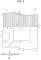
FIG. 2 is an enlarged view illustrating a tensioning device and a reed; -
FIG. 3 is an enlarged view illustrating the tensioning device and reed dents; -
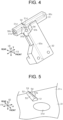
FIG. 4 is a perspective view illustrating the tensioning device; -
FIG. 5 is an enlarged view illustrating the tensioning device; -
FIG. 6 is a view schematically illustrating an attachment of the tensioning device to the reed; and -
FIG. 7 is an enlarged view illustrating a tensioning device and reed dents according to a modification. - The following will describe an embodiment of a tensioning device for an air jet loom with reference to
FIG. 1 to FIG. 6 . - As illustrated in
FIG. 1 , anair jet loom 100 includes a main nozzle M, a sub nozzle S, areed 10, asley 20, and atensioning device 30. A weftyarn guide passage 10a through which a weft yarn Y travels is formed in thereed 10. A direction in which the weftyarn guide passage 10a extends coincides with a longitudinal direction of thesley 20. The weft yarn Y is inserted from the main nozzle M into the weftyarn guide passage 10a. That is, theair jet loom 100 inserts the weft yarn Y along the weftyarn guide passage 10a formed in thereed 10. The weft yarn Y travels in the longitudinal direction of thesley 20. A direction in which the weft yarn Y travels is referred to as a weft insertion direction W. Hereinafter, a side in the weft insertion direction W on which the main nozzle M is located is referred to as an "upstream" side, and a side in the weft insertion direction W opposite to the upstream side is referred to as a "downstream" side. - In the
air jet loom 100, the weft yarn Y is beaten by thereed 10 after being inserted. A direction in which thereed 10 moves during the beating is referred to as a front-rear direction FB. The front-rear direction FB is orthogonal to the weft insertion direction W. A direction orthogonal to each of the weft insertion direction W and the front-rear direction FB is referred to as an up-down direction UD. The up-down direction UD coincides with a vertical direction. - In the
air jet loom 100, thereed 10 and the weft yarn Y are arranged in the front-rear direction FB. Theair jet loom 100 weaves fabric C. Aside in the front-rear direction FB on which the woven fabric C is wound is referred to as a "front" side, and a side in the front-rear direction FB opposite to the front side is referred to as a "rear" side. - The main nozzle M is provided on the
sley 20. The main nozzle M is fixed to thesley 20 and located on the upstream side in the weft insertion direction W. The weft yarn Y is inserted from the main nozzle M into the weftyarn guide passage 10a. The main nozzle M is attached to thesley 20 so that its position is adjustable in the weft insertion direction W. - The sub nozzle S is fixed to the
sley 20. Air is injected from the sub nozzle S into the weftyarn guide passage 10a. A direction in which air is injected from the sub nozzle S is along the weft insertion direction W. Then, the weft yarn Y travels in the weft insertion direction W through the weftyarn guide passage 10a by the air injection from the main nozzle M and the sub nozzle S. - The
reed 10 has a plurality of thereed dents 11 and aholding member 12. - The
holding member 12 holds the plurality of thereed dents 11. The plurality of thereed dents 11 are arranged in a line in the weft insertion direction W of the weft yarn Y. That is, in theair jet loom 100, the plurality of thereed dents 11 are arranged side by side in the weft insertion direction W of the weft yarn Y. Agap 10b is defined by any adjacent two of the reed dents 11 in the weft insertion direction W therebetween. In other words, in thereed 10, thegaps 10b are defined by the reed dents 11 arranged side by side. In thereed 10, a plurality of thegaps 10b are formed. A warp yarn T passes through each of thegap 10b. However, the warp yarn T does not pass through each of thegaps 10b located at a position where thetensioning device 30, which will be described later, is provided. In thereed 10, the intervals of thegaps 10b are constant excluding thegap 10b into which aprotrusion 50 illustrated inFIG. 2 is inserted. - As illustrated in
FIG. 1 andFIG. 3 , each of the reed dents 11 has arecess 13. The reed dents 11 are each recessed from its front surface toward its rear surface to form therecess 13. The reed dents 11 each have arear side edge 13a, anupper side edge 13b, and alower side edge 13c. Therecess 13 is defined by therear side edge 13a, theupper side edge 13b, and thelower side edge 13c. Therear side edge 13a is located at the most rearward position from the front surface of thereed dent 11, as viewed in the weft insertion direction W. Therear side edge 13a extends in the up-down direction UD of thereed dent 11. Theupper side edge 13b extends from an upper end of therear side edge 13a toward the front surface of thereed dent 11. Theupper side edge 13b extends in the front-rear direction FB of thereed dent 11. Thelower side edge 13c extends from a lower end of therear side edge 13a toward the front surface of thereed dent 11. Thelower side edge 13c extends in the front-rear direction FB of thereed dent 11. Note that the weftyarn guide passage 10a is formed of therecesses 13 of all of the reed dents 11, which are arranged side by side in the weft insertion direction W. - The
reed 10 has arear wall 10c, anupper wall 10d, and alower wall 10e. Therear wall 10c is a portion of thereed 10 in which a plurality of the rear side edges 13a are arranged. Accordingly, therear wall 10c is formed of the plurality of the rear side edges 13a arranged side by side in the weft insertion direction W. Theupper wall 10d is a portion of thereed 10 in which a plurality of the upper side edges 13b are arranged. Accordingly, theupper wall 10d is formed of the plurality of the upper side edges 13b arranged side by side in the weft insertion direction W. Thelower wall 10e is a portion of thereed 10 in which a plurality of thelower side edges 13c are arranged. Accordingly, thelower wall 10e is formed of the plurality of thelower side edges 13c arranged side by side in the weft insertion direction W. The weftyarn guide passage 10a is defined by therear wall 10c, theupper wall 10d, and thelower wall 10e. That is, thereed 10 has therear wall 10c that partially defines the weftyarn guide passage 10a. - As illustrated in
FIG. 1 , the warp yarn T passes through each of thegaps 10b. The warp yarn T extends in the front-rear direction FB. The air jet loom 100 weaves the fabric C by interlacing the weft yarns Y and the warp yarns T. The woven fabric C is spread in front of the air jet loom 100. A selvedge yarn T1 passes through each of thegaps 10b upstream of thetensioning device 30. A plurality of the selvedge yarns T1 form a waste selvedge C1 together with some of the weft yarns Y. - The
tensioning device 30 captures an end portion of the weft yarn Y and tensions the weft yarn Y. In addition, thetensioning device 30 appropriately tensions the weft yarn Y to prevent the weft yarn Y from becoming loose. - The
tensioning device 30 is disposed in front of thereed 10. Thetensioning device 30 is located near the end portion of the weft yarn Y inserted into the weftyarn guide passage 10a and downstream of the selvedge yarns T1 of the waste selvedge C1 in the weft insertion direction W. - The
tensioning device 30 has apassage defining portion 31 and asupply portion 32. Thetensioning device 30 is fixed to thesley 20 by attaching a lower end portion of thesupply portion 32 in the up-down direction UD to thesley 20. - The
passage defining portion 31 is formed in a cylindrical shape. Thepassage defining portion 31 is provided at an upper end portion of thesupply portion 32 in the up-down direction UD. Thepassage defining portion 31 is disposed in the weftyarn guide passage 10a. Thepassage defining portion 31 is accommodated in the weftyarn guide passage 10a. Thepassage defining portion 31 is disposed so as to extend over a plurality of the reed dents 11. - As illustrated in
FIG. 2 to FIG. 4 , thepassage defining portion 31 has a passage portionrear surface 31e and a passage portionupper surface 31c as an upper surface of thepassage defining portion 31. The passage portionrear surface 31e is one of outer surfaces of thepassage defining portion 31, which extends along the plurality of therear side edges 13a. The passage portionupper surface 31c is one of the outer surfaces of thepassage defining portion 31, which extends along the plurality of the upper side edges 13b. In other words, thepassage defining portion 31 has the passage portionupper surface 31c facing theupper wall 10d of thereed 10, which partially defines the weftyarn guide passage 10a. - Each of the passage portion
rear surface 31e and the passage portionupper surface 31c of thepassage defining portion 31 is in contact with thereed 10. That is, thetensioning device 30 is in contact with the plurality of the reed dents 11 on each of the passage portionrear surface 31e and the passage portionupper surface 31c of thepassage defining portion 31. - The
passage defining portion 31 defines a weft yarn traveling passage 31a. The weft yarn traveling passage 31a extends along the weft insertion direction W. That is, thepassage defining portion 31 defines the weft yarn traveling passage 31a extending along the weftyarn guide passage 10a. Ayarn inlet 30b of the weft yarn traveling passage 31a is opened in an upstream end of thepassage defining portion 31 in the weft insertion direction W. The weft yarn Y is introduced into the weft yarn traveling passage 31a through theyarn inlet 30b. Ayarn outlet 30c of the weft yarn traveling passage 31a is opened in a downstream end of thepassage defining portion 31 in the weft insertion direction W. - As illustrated in
FIG. 1 andFIG. 4 , thepassage defining portion 31 has anair injection portion 34. A firstair injection port 34a is formed in theair injection portion 34. The firstair injection port 34a is connected to a firstair supply tube 41. Air supplied through the firstair supply tube 41 is injected from the firstair injection port 34a into the weft yarn traveling passage 31a. - The
supply portion 32 is located in front of thepassage defining portion 31 in the front-rear direction FB and below thepassage defining portion 31 in the up-down direction UD. The upper end portion of thesupply portion 32 is connected to thepassage defining portion 31, and the lower end portion of thesupply portion 32 is attached to thesley 20. - As illustrated in
FIG. 4 , astretch air passage 32a is defined in thesupply portion 32. Thestretch air passage 32a extends in the up-down direction UD inside thesupply portion 32. A lower end of thestretch air passage 32a is connected to a secondair supply tube 42 illustrated inFIG. 1 . Thestretch air passage 32a has, at an upper end thereof, a secondair injection port 32b. As illustrated inFIG. 2 andFIG. 4 , the secondair injection port 32b is opened toward an inside of the weft yarn traveling passage 31a. That is, thestretch air passage 32a communicates with the weft yarn traveling passage 31a through the secondair injection port 32b. In addition, thestretch air passage 32a extends in a direction different from the direction in which the weft yarn traveling passage 31a extends, and the secondair injection port 32b is opened toward a direction orthogonal to the direction in which the weft yarn traveling passage 31a extends. - As illustrated in
FIGS. 2 to 4 , thepassage defining portion 31 has a passage defininginner surface 31b that defines the weft yarn traveling passage 31a. Thepassage defining portion 31 has a stretchair exhaust port 31d as an air exhaust port. The stretchair exhaust port 31d is opened in the passage defininginner surface 31b and the passage portionupper surface 31c. The stretchair exhaust port 31d is aligned with the secondair injection port 32b in the front-rear direction FB and located above the stretchair exhaust port 31d in the up-down direction UD. Air injected from the secondair injection port 32b into the weft yarn traveling passage 31a crosses the weft yarn traveling passage 31a, and then, is discharged from the stretchair exhaust port 31d to the outside of thetensioning device 30. That is, thepassage defining portion 31 has the stretchair exhaust port 31d that is opened in the passage portionupper surface 31c and communicates with the weft yarn traveling passage 31a. - As illustrated in
FIG. 1 , thetensioning device 30 is provided in front of thereed 10. Thetensioning device 30 is provided in the air jet loom 100 such that the weft yarn traveling passage 31a forms a part of the weftyarn guide passage 10a in the weft insertion direction W. Thetensioning device 30 is provided in the air jet loom 100 such that the passage portionupper surface 31c faces theupper wall 10d and the passage portionrear surface 31e faces therear wall 10c. The passage portionupper surface 31c is in contact with theupper wall 10d. In addition, the passage portionrear surface 31e is in contact with therear wall 10c. That is, each of the passage portionupper surface 31c and the passage portionrear surface 31e of thepassage defining portion 31 is in contact with thereed 10. - As illustrated in
FIG. 2 , the stretchair exhaust port 31d faces a part of theupper wall 10d. In other words, the stretchair exhaust port 31d faces the upper side edges 13b of a part of the plurality of the reed dents 11 that form thereed 10. The stretchair exhaust port 31d faces each of thegaps 10b defined by such a part of the reed dents 11. That is, the stretchair exhaust port 31d faces at least one of the plurality of thegaps 10b formed in thereed 10. Thegaps 10b facing the stretchair exhaust port 31d communicate with the weft yarn traveling passage 31a through the stretchair exhaust port 31d. - As illustrated in
FIGS. 2 to 4 , thetensioning device 30 has theprotrusion 50. Theprotrusion 50 is provided on the passage portionupper surface 31c. Theprotrusion 50 is formed integrally with thepassage defining portion 31. Note that theprotrusion 50 may be joined to the passage portionupper surface 31c after being formed separately from thepassage defining portion 31. - As illustrated in
FIG. 4 and FIG. 5 , theprotrusion 50 has a longitudinal side extending in the front-rear direction FB. A first end of theprotrusion 50 in a longitudinal direction thereof corresponds to a front end of theprotrusion 50 in the front-rear direction FB, and a second end of theprotrusion 50 in the longitudinal direction thereof corresponds to a rear end of theprotrusion 50 in the front-rear direction FB. Theprotrusion 50 has a shape in which a width of theprotrusion 50 in the weft insertion direction W becomes smaller as theprotrusion 50 extends from the first end toward the second end of theprotrusion 50 in the longitudinal direction thereof. In other words, the width of theprotrusion 50 in the weft insertion direction W becomes larger as theprotrusion 50 extends from the second end toward the first end of theprotrusion 50 in the longitudinal direction thereof. Theprotrusion 50 has aprotrusion front surface 51 and a protrusionrear surface 52 as end surfaces in the longitudinal direction of theprotrusion 50. Theprotrusion front surface 51 is a front end surface of theprotrusion 50 in the front-rear direction FB, and the protrusionrear surface 52 is a rear end surface of theprotrusion 50 in the front-rear direction FB. Each of theprotrusion front surface 51 and the protrusionrear surface 52 is orthogonal to the passage portionupper surface 31c and continuous with the passage portionupper surface 31c. - The
protrusion front surface 51 and the protrusionrear surface 52 are arranged in the front-rear direction FB. A width of theprotrusion front surface 51 in the weft insertion direction W is larger than a width of the protrusionrear surface 52 in the weft insertion direction W. Regarding the front-rear direction FB, theprotrusion 50 has a maximum width in the weft insertion direction W at theprotrusion front surface 51 and a minimum width in the weft insertion direction W at the protrusionrear surface 52. The width of theprotrusion front surface 51 in the weft insertion direction W is smaller than a hole diameter of the stretchair exhaust port 31d. In other words, the width of theprotrusion 50 in the weft insertion direction W is equal to or smaller than a maximum length of the stretchair exhaust port 31d in the weft insertion direction W. - A first end of the
protrusion 50 in the up-down direction UD corresponds to a lower end of theprotrusion 50, and is coupled to thepassage defining portion 31. A second end of theprotrusion 50 in the up-down direction UD corresponds to an upper end of theprotrusion 50. Theprotrusion 50 has a protrusiondistal end surface 53 that is oriented in the same direction as a direction in which the passage portionupper surface 31c is oriented. The width of theprotrusion 50 in the weft insertion direction W becomes smaller as theprotrusion 50 extends from the first end to the second end of theprotrusion 50 in the up-down direction UD. In other words, a width of the protrusiondistal end surface 53 in the weft insertion direction W is smaller than the width of theprotrusion 50 in the weft insertion direction W on a side of the first end of theprotrusion 50 in the up-down direction UD. That is, the width of theprotrusion 50 in the weft insertion direction W becomes smaller as theprotrusion 50 extends away from the passage portionupper surface 31c in the up-down direction UD. - As illustrated in
FIG. 5 , the protrusiondistal end surface 53 has edges 53a. Each of connectingsurfaces 54 extends from the corresponding one of the edges 53a in the weft insertion direction W. The connecting surfaces 54 connect the protrusiondistal end surface 53 to the passage portionupper surface 31c. Theprotrusion front surface 51 extends from one edge 53a located at a front end of theprotrusion 50 in the front-rear direction FB. The protrusionrear surface 52 extends from one edge 53a located at a rear end of theprotrusion 50 in the front-rear direction FB. The connecting surfaces 54 are surfaces located on both sides of theprotrusion 50 in the weft insertion direction W, of outer surfaces of theprotrusion 50. The connecting surfaces 54 are each curved so as to form a gentle arc as the connectingsurface 54 extends from the second end toward the first end in the up-down direction UD. The connecting surfaces 54 are connected to each of theprotrusion front surface 51 and the protrusionrear surface 52 in the front-rear direction FB. That is, the outer surfaces of theprotrusion 50 are formed of theprotrusion front surface 51, the protrusionrear surface 52, the protrusiondistal end surface 53, and the connecting surfaces 54. - As illustrated in
FIG. 3 , on the passage portionupper surface 31c, theprotrusion 50 and the stretchair exhaust port 31d are arranged in the front-rear direction FB. Theprotrusion 50 is located closer to therear wall 10c of thereed 10 than the stretchair exhaust port 31d. That is, theprotrusion 50 is located between the stretchair exhaust port 31d and therear wall 10c in the front-rear direction FB. As illustrated inFIG. 5 , theprotrusion 50 is located at a position such that on the passage portionupper surface 31c, theprotrusion front surface 51 and an opening edge of the stretchair exhaust port 31d on a side of the passage portionupper surface 31c are arranged in the front-rear direction FB through the passage portionupper surface 31c. Theprotrusion front surface 51 is connected to an inner peripheral surface that defines the stretchair exhaust port 31d through the passage portionupper surface 31c in the front-rear direction FB. - As illustrated in
FIG. 6 , the width of theprotrusion front surface 51 in the weft insertion direction W is larger than a width of each of thegaps 10b. Furthermore, the width of the protrusionrear surface 52 in the weft insertion direction W is smaller than the width of each of thegaps 10b. That is, the width of theprotrusion 50 in the weft insertion direction W at theprotrusion front surface 51 is larger than the width of each of thegaps 10b, and the width of theprotrusion 50 in the weft insertion direction W at the protrusionrear surface 52 is smaller than the width of each of thegaps 10b. In other words, the width of theprotrusion 50 in the weft insertion direction W becomes smaller as theprotrusion 50 extends away from the stretchair exhaust port 31d in the front-rear direction FB. - As illustrated in
FIG. 2 , each of the connectingsurfaces 54 of theprotrusion 50 on a side near the passage portionupper surface 31c comes in contact with the corresponding one of the two reed dents 11, so that theprotrusion 50 widens thegap 10b in the weft insertion direction W, which is defined by the two reed dents 11. The width of thegap 10b of the plurality of thegaps 10b formed in thereed 10, which is defined by the two reed dents 11 in contact with theprotrusion 50, is larger than that of each of theother gaps 10b in the weft insertion direction W. The width of the wideninggap 10b is determined by the width of theprotrusion front surface 51 in the weft insertion direction W. That is, thepassage defining portion 31 has theprotrusion 50 that comes in contact with the two reed dents 11 such that theprotrusion 50 widens thegap 10b facing the stretchair exhaust port 31d. - The
tensioning device 30 is provided in the air jet loom 100 by inserting thepassage defining portion 31 into the weftyarn guide passage 10a from a front of thereed 10. InFIG. 6 , thetensioning device 30 before being attached to thereed 10 is illustrated by a long dashed double short dashed line, and thetensioning device 30 after being attached to thereed 10 is illustrated by a solid line. In the process of attaching thetensioning device 30 to the air jet loom 100, theprotrusion 50 moves from a position where the protrusionrear surface 52 faces thegap 10b in the front-rear direction FB to a position where theprotrusion 50 is in contact with the reed dents 11 that defines thegap 10b. In the process of this movement, the connectingsurfaces 54 of theprotrusion 50 are brought into contact with the reed dents 11 after the protrusionrear surface 52 is inserted into thegap 10b. The width of theprotrusion 50 in the weft insertion direction W becomes larger as theprotrusion 50 extends from the protrusionrear surface 52 to theprotrusion front surface 51. That is, in the process of inserting theprotrusion 50 into thegap 10b, thegap 10b, which is defined by the reed dents 11 in contact with theprotrusion 50, widens as theprotrusion 50 widens in the weft insertion direction W. When theprotrusion 50 is inserted in thegap 10b, the width of thegap 10b is larger near theprotrusion front surface 51 than that near the protrusionrear surface 52. - As illustrated in
FIG. 3 andFIG. 6 , thetensioning device 30 is inserted into thereed 10 until thetensioning device 30 reaches a position where the stretchair exhaust port 31d faces thegap 10b widened by theprotrusion 50 and the passage portionrear surface 31e is in contact with therear wall 10c. The stretchair exhaust port 31d is located near theprotrusion front surface 51 of theprotrusion 50 in the front-rear direction FB, and the stretchair exhaust port 31d and the reed dents 11 are arranged in the up-down direction UD. In thetensioning device 30, while the passage portionupper surface 31c is kept in contact with theupper wall 10d in the up-down direction UD, thepassage defining portion 31 is inserted into the weftyarn guide passage 10a. - As illustrated in
FIG. 1 , in the weft insertion of the weft yarn Y, the air jet loom 100 causes the weft yarn Y to travel through the weftyarn guide passage 10a by injecting air from the main nozzle M and the sub nozzle S. The weft yarn Y travels in the weft insertion direction W from the upstream side to the downstream side of the weft yarn guide passage with the air flow from the main nozzle M. After the weft yarn Y reaches a position of the selvedge yarns T1, the weft yarn Y is introduced into the weft yarn traveling passage 31a defined by thepassage defining portion 31 through theyarn inlet 30b. - When the weft yarn Y is introduced into the
yarn inlet 30b, air is supplied from an air supply source, which is not illustrated, to theair injection portion 34 from the firstair supply tube 41. In theair injection portion 34, the air is injected into the weft yarn traveling passage 31a through the firstair injection port 34a. The weft yarn Y is captured and tensioned in the weft yarn traveling passage 31a by the air injection into the weft yarn traveling passage 31a from theair injection portion 34. That is, thetensioning device 30 for the air jet loom 100 injects air into the weft yarn traveling passage 31a in order to tension the weft yarn Y and discharges the air from the stretchair exhaust port 31d. - The weft yarn Y passes through the weft yarn traveling passage 31a, and then, the weft yarn Y comes out of the
tensioning device 30 through theyarn outlet 30c. After the weft yarn Y is introduced into theyarn outlet 30c, air is supplied from an air supply source, which is not illustrated, to thestretch air passage 32a through the secondair supply tube 42. That is, air is supplied to thesupply portion 32 through the secondair supply tube 42. In thesupply portion 32, air supplied through the secondair supply tube 42 passes through thestretch air passage 32a and is injected into the weft yarn traveling passage 31a from the secondair injection port 32b. The air is injected from the secondair injection port 32b, crosses the weft yarn traveling passage 31a through which the weft yarn Y travels, and is discharged to the outside of the weft yarn traveling passage 31a through the stretchair exhaust port 31d. That is, the air injected from the secondair injection port 32b crosses the weft yarn Y, and then, is discharged through the stretchair exhaust port 31d. - When the air is discharged through the stretch
air exhaust port 31d, air in a vicinity of the stretchair exhaust port 31d inside the weft yarn traveling passage 31a flows into the stretchair exhaust port 31d. A direction of this flow of the air coincides with the up-down direction UD, and is orthogonal to the direction in which the weft yarn traveling passage 31a extends. That is, the weft yarn Y traveling through the weft yarn traveling passage 31a is pressed against an opening edge of the stretchair exhaust port 31d on a side of the weft yarn traveling passage 31a by the air discharged through the stretchair exhaust port 31d. The weft yarn Y is tensioned in the weft insertion direction W by this pressing. - The air discharged through the stretch
air exhaust port 31d flows into thegap 10b facing the stretchair exhaust port 31d. - The following will describe an operation of the present embodiment.
- In the process of the weaving by the air jet loom 100, fluff is generated from the weft yarn Y. The fluff generated from the weft yarn Y is discharged together with the air toward the
reed 10 through the stretchair exhaust port 31d. The air discharged through the stretchair exhaust port 31d flows into thegap 10b facing the stretchair exhaust port 31d. Thegap 10b into which this air flows is defined by the reed dents 11 in contact with theprotrusion 50. That is, the air discharged from the stretchair exhaust port 31d flows into thegap 10b that is widened in the weft insertion direction W by theprotrusion 50. - The following will describe advantageous effects of the present embodiment.
- (1) The air discharged to the outside of the
passage defining portion 31 through the stretchair exhaust port 31d flows into thegap 10b facing the stretchair exhaust port 31d. Theprotrusion 50 provided on the passage portionupper surface 31c widens thegap 10b in the weft insertion direction W. This makes it possible to suppress that the fluff discharged together with the air flowing through the stretchair exhaust port 31d piles up in thegap 10b facing the stretchair exhaust port 31d. As a result, thetensioning device 30 for the air jet loom 100 suppresses that the fluff piles up in thegap 10b. - (2) An amount of the widening of the
gap 10b by theprotrusion 50 is largest at a point of thegap 10b where the reed dents 11 are in contact with theprotrusion 50 since the reed dents 11 are elastically deformed. Then, the amount of the widening of thegap 10b by theprotrusion 50 decreases at a point of thegap 10b as a distance between the point and theprotrusion 50 increases in the front-rear direction FB and the up-down direction UD. That is, the width of thegap 10b at the point away from theprotrusion 50 becomes easily smaller than a desired width of thegap 10b directly above the stretchair exhaust port 31d as a distance between the stretchair exhaust port 31d and theprotrusion 50 in the front-rear direction FB and the up-down direction UD increases. Accordingly, in thetensioning device 30 for the air jet loom 100, both theprotrusion 50 and the stretchair exhaust port 31d are provided on the passage portionupper surface 31c, so that thegap 10b directly above the stretchair exhaust port 31d may be widened to the desired width. - (3) The
protrusion 50 is provided on the passage portionupper surface 31c and located closer to therear wall 10c than the stretchair exhaust port 31d in the front-rear direction FB. In this case, the width of thegap 10b widened by theprotrusion 50 becomes larger at a point closer to the stretchair exhaust port 31d than theprotrusion 50, and becomes smaller at a point closer to therear wall 10c than theprotrusion 50. For example, as compared with a case where theprotrusion 50 is provided in front of the stretchair exhaust port 31d, thegap 10b directly above the stretchair exhaust port 31d may be made wider. As a result, thetensioning device 30 for the air jet loom 100 may widen thegap 10b directly above the stretchair exhaust port 31d by theprotrusion 50. - (4) When the
passage defining portion 31 is inserted into the weftyarn guide passage 10a, the width of thegap 10b into which theprotrusion 50 is inserted becomes larger as the width of theprotrusion 50 increases in the weft insertion direction W. Accordingly, in thetensioning device 30 for the air jet loom 100, as compared with a case where theprotrusion 50 has a cross-sectional shape with a constant width when viewed in the up-down direction UD, thepassage defining portion 31 is easily inserted into the weftyarn guide passage 10a. - In addition, since the
protrusion 50 has the above-described configuration, in thetensioning device 30, thepassage defining portion 31 may be inserted into the weftyarn guide passage 10a while thegap 10b is widened step by step. As a result, in thetensioning device 30 for the air jet loom 100, thegap 10b may be widened by theprotrusion 50 while load applied to the reed dents 11 is reduced. - (5) The width of the
protrusion 50 in the weft insertion direction W becomes smaller as theprotrusion 50 extends away from the passage portionupper surface 31c in the up-down direction UD. With this shape, the width of theprotrusion 50 in the weft insertion direction W is largest at the portion of theprotrusion 50 in the up-down direction UD, which is connected to the passage portionupper surface 31c, and thegap 10b between the reed dents 11 is widened at the portion of theprotrusion 50. That is, in thetensioning device 30, as compared with theprotrusion 50 has a cross-sectional shape with the constant width when viewed in the front-rear direction FB, a contact area of theprotrusion 50 and each of the reed dents 11 is small. As a result, in thetensioning device 30 for the air jet loom 100, load applied to the reed dents 11 by theprotrusion 50 may be reduced. - (6) The width of the
gap 10b that may be widened by theprotrusion 50 is equal to or smaller than the maximum length of the stretchair exhaust port 31d in the weft insertion direction W. The fluff that may affect the air exhaust through the stretchair exhaust port 31d piles up in thegap 10b located directly above the stretchair exhaust port 31d. That is, the width of thegap 10b that is desired to be ensured by theprotrusion 50 corresponds to the maximum length of the stretchair exhaust port 31d in the weft insertion direction W. In addition, widening thegap 10b by theprotrusion 50 beyond the maximum length of the stretchair exhaust port 31d applies load to the reed dents 11 that form the gap widened by theprotrusion 50. Thus, in thetensioning device 30 for the air jet loom 100, the width of thegap 10b that may be widened by theprotrusion 50 is set to be equal to or smaller than the maximum length of the stretchair exhaust port 31d, so that the fluff that piles up in thegap 10b is reduced while the load applied to the reed dents 11 defining thegap 10b is suppressed. - The above-described present embodiment may be modified as follows. The present embodiment and the following modifications may be combined with each other as long as they do not technically contradict each other.
- The width of the
protrusion 50 in the weft insertion direction W need not be equal to or smaller than the maximum length of the stretchair exhaust port 31d in the weft insertion direction W. - The width of the
protrusion 50 in the weft insertion direction W need not become smaller as theprotrusion 50 extends away from the passage portionupper surface 31c in the up-down direction UD. For example, the connectingsurfaces 54 of theprotrusion 50 may be surfaces orthogonal to the passage portionupper surface 31c and the protrusiondistal end surface 53. - The width of the
protrusion 50 in the weft insertion direction W need not become smaller as theprotrusion 50 extends away from the stretchair exhaust port 31d in the front-rear direction FB. In this case, theprotrusion 50 has the protrusionrear surface 52 that has the same width as that of theprotrusion front surface 51 in the weft insertion direction W. That is, theprotrusion 50 is formed in a columnar shape whose axial direction coincides with the front-rear direction FB and that has theprotrusion front surface 51 and the protrusionrear surface 52 as the end surfaces. - The
protrusion 50 need not be provided between the stretchair exhaust port 31d and therear wall 10c in the front-to-rear direction FB on the passage portionupper surface 31c. For example, theprotrusion 50 may be provided in front of the stretchair exhaust port 31d in the front-rear direction FB on the passage portionupper surface 31c. - The
protrusion 50 need not be provided on the passage portionupper surface 31c. For example, as illustrated inFIG. 7 , theprotrusion 50 may be provided on the passage portionrear surface 31e. In this case, theprotrusion 50 is provided at a position where theprotrusion 50 is in contact with the reed dents 11 that define thegap 10b facing the stretchair exhaust port 31d, of the reed dents 11 that form therear wall 10c. - The
tensioning device 30 is inserted from the front of thereed 10 and provided at a position where the passage portionrear surface 31e is in contact with therear wall 10c. When thetensioning device 30 is provided, in theprotrusion 50, after the protrusiondistal end surface 53 is inserted into thegap 10b, the connectingsurfaces 54 are brought into contact with the reed dents 11 that define thegap 10b. That is, when theprotrusion 50 is provided on the passage portionrear surface 31e, theprotrusion 50 preferably has the connectingsurfaces 54 such that the width of theprotrusion 50 in the weft insertion direction W becomes smaller as theprotrusion 50 extends from the passage portionrear surface 31e toward the protrusiondistal end surface 53. In theprotrusion 50 having the above-described configuration, when thetensioning device 30 is inserted into thereed 10, the load applied to the reed dents 11 in contact with theprotrusion 50 is reduced. - The stretch
air exhaust port 31d may face a plurality of thegaps 10b. - The
protrusion 50 may be in contact with one of the two reed dents 11 that define thegap 10b facing the stretchair exhaust port 31d to widen thegap 10b. In this case, the width of theprotrusion front surface 51 in the weft insertion direction W may be smaller than the width of thegap 10b in the weft insertion direction W.
Claims (6)
- A tensioning device (30) for an air jet loom (100) that inserts a weft yarn (Y) along a weft yarn guide passage (10a) formed in a reed (10), the reed (10) being formed of a plurality of reed dents (11) that are arranged side by side with gaps (10b) in a weft insertion direction (W) in which the weft yarn (Y) is inserted,the tensioning device (30) comprising a passage defining portion (31) that defines a weft yarn traveling passage (31a) extending along the weft yarn guide passage (10a),the passage defining portion (31) having:an upper surface (31c) facing an upper wall (10d) of the reed (10), the upper wall (10d) partially defining the weft yarn guide passage (10a); andan air exhaust port (31d) being opened in the upper surface (31c) and communicating with the weft yarn traveling passage (31a),the air exhaust port (31d) facing at least one of the gaps (10b), andthe tensioning device (30) being configured to tension the weft yarn (Y) by injecting air into the weft yarn traveling passage (31a), the air being discharged through the air exhaust port (31d), characterized in thatthe passage defining portion (31) has a protrusion (50) that comes in contact with at least one of adjacent two of the reed dents (11) such that the protrusion (50) widens one of the gaps (10b) facing the air exhaust port (31d) and defined by the adjacent two reed dents (11).
- The tensioning device (30) for the air jet loom (100) according to claim 1, characterized in that
the protrusion (50) is provided on the upper surface (31c). - The tensioning device (30) for the air jet loom (100) according to claim 2, characterized in thatthe reed (10) has a rear wall (10c) that partially defines the weft yarn guide passage (10a) in a front-rear direction (FB) orthogonal to each of the weft insertion direction (W) and an up-down direction (UD), andthe protrusion (50) is located between the air exhaust port (31d) and the rear wall (10c).
- The tensioning device (30) for the air jet loom (100) according to claim 3, characterized in that
a width of the protrusion (50) in the weft yarn direction (W) becomes smaller as the protrusion (50) extends away from the air exhaust port (31d) in the front-rear direction (FB) orthogonal to each of the weft insertion direction (W) and the up-down direction (UD). - The tensioning device (30) for the air jet loom (100) according to claim 2, characterized in that
a width of the protrusion (50) in the weft yarn direction (W) becomes smaller as the protrusion (50) extends away from the upper surface (31c) in the up-down direction (UD). - The tensioning device (30) for the air jet loom (100) according to claim 5, characterized in that
the width of the protrusion (50) in the weft insertion direction (W) is equal to or smaller than a maximum length of the air exhaust port (31d) in the weft insertion direction (W).
Applications Claiming Priority (1)
| Application Number | Priority Date | Filing Date | Title |
|---|---|---|---|
| JP2023207420A JP2025091891A (en) | 2023-12-08 | 2023-12-08 | Tensioning device for air jet looms |
Publications (2)
| Publication Number | Publication Date |
|---|---|
| EP4567173A1 true EP4567173A1 (en) | 2025-06-11 |
| EP4567173B1 EP4567173B1 (en) | 2026-03-25 |
Family
ID=93562967
Family Applications (1)
| Application Number | Title | Priority Date | Filing Date |
|---|---|---|---|
| EP24212901.3A Active EP4567173B1 (en) | 2023-12-08 | 2024-11-14 | Tensioning device for air jet loom |
Country Status (3)
| Country | Link |
|---|---|
| EP (1) | EP4567173B1 (en) |
| JP (1) | JP2025091891A (en) |
| CN (1) | CN120119384A (en) |
Citations (2)
| Publication number | Priority date | Publication date | Assignee | Title |
|---|---|---|---|---|
| JP2016084557A (en) * | 2014-10-27 | 2016-05-19 | 株式会社豊田自動織機 | Weft tension applying device for air jet loom |
| JP2022014545A (en) | 2020-07-07 | 2022-01-20 | 株式会社豊田自動織機 | Weft tensioning device |
-
2023
- 2023-12-08 JP JP2023207420A patent/JP2025091891A/en active Pending
-
2024
- 2024-11-14 EP EP24212901.3A patent/EP4567173B1/en active Active
- 2024-12-03 CN CN202411759297.XA patent/CN120119384A/en active Pending
Patent Citations (2)
| Publication number | Priority date | Publication date | Assignee | Title |
|---|---|---|---|---|
| JP2016084557A (en) * | 2014-10-27 | 2016-05-19 | 株式会社豊田自動織機 | Weft tension applying device for air jet loom |
| JP2022014545A (en) | 2020-07-07 | 2022-01-20 | 株式会社豊田自動織機 | Weft tensioning device |
Also Published As
| Publication number | Publication date |
|---|---|
| EP4567173B1 (en) | 2026-03-25 |
| JP2025091891A (en) | 2025-06-19 |
| CN120119384A (en) | 2025-06-10 |
Similar Documents
| Publication | Publication Date | Title |
|---|---|---|
| CN102094283B (en) | Weaving edge forming device of rubber strengthening textile weaving loom | |
| EP0691430B1 (en) | Weft inserting device for air jet loom | |
| IE44333B1 (en) | A fluid jet loom | |
| EP4567173B1 (en) | Tensioning device for air jet loom | |
| CN113913999B (en) | Weft tension applying device | |
| CN1922349B (en) | Weft tension device for jet looms | |
| US6536482B1 (en) | Auxiliary nozzle for a weaving machine | |
| EP0258887A2 (en) | Multiple-phase weaving fluid jet loom | |
| JP3405962B2 (en) | Split reed | |
| JP2008063715A (en) | Process and stretching device for holding weft thread | |
| EP1088922A1 (en) | Tuck-in apparatus for shuttleless loom | |
| EP3048194A1 (en) | Selvage holding apparatus for loom, loom, and method for manufacturing woven fabric | |
| JP2003278052A (en) | Method for entangling non-entangled or partially entangled weft, especially synthetic filament weft and weaving loom for performing the method | |
| JP5369915B2 (en) | Weft tension applying device for air jet loom | |
| JP2007308825A (en) | Weft insertion device in air jet loom | |
| CN120193365A (en) | Air jet loom | |
| JP2023156763A (en) | Air jet loom weft tension applying device | |
| JP2956828B2 (en) | Weft end capture device of loom | |
| JP2004190200A (en) | Weft tension applying device for fluid jet loom | |
| JPH07279002A (en) | Air jet loom weft insertion device | |
| KR100859994B1 (en) | Weft Yarn Device in Air Jet Room | |
| JPS5925888Y2 (en) | Auxiliary fluid injection device in jettrum | |
| JP2009155754A (en) | Reed of air jet loom | |
| JPH08325895A (en) | Apparatus for relaxing weft yarn tension of loom | |
| JPS602745A (en) | Weft yarn inducing apparatus of air jet type loom |
Legal Events
| Date | Code | Title | Description |
|---|---|---|---|
| PUAI | Public reference made under article 153(3) epc to a published international application that has entered the european phase |
Free format text: ORIGINAL CODE: 0009012 |
|
| STAA | Information on the status of an ep patent application or granted ep patent |
Free format text: STATUS: REQUEST FOR EXAMINATION WAS MADE |
|
| 17P | Request for examination filed |
Effective date: 20241114 |
|
| AK | Designated contracting states |
Kind code of ref document: A1 Designated state(s): AL AT BE BG CH CY CZ DE DK EE ES FI FR GB GR HR HU IE IS IT LI LT LU LV MC ME MK MT NL NO PL PT RO RS SE SI SK SM TR |
|
| GRAP | Despatch of communication of intention to grant a patent |
Free format text: ORIGINAL CODE: EPIDOSNIGR1 |
|
| STAA | Information on the status of an ep patent application or granted ep patent |
Free format text: STATUS: GRANT OF PATENT IS INTENDED |
|
| INTG | Intention to grant announced |
Effective date: 20251013 |
|
| GRAS | Grant fee paid |
Free format text: ORIGINAL CODE: EPIDOSNIGR3 |
|
| GRAA | (expected) grant |
Free format text: ORIGINAL CODE: 0009210 |
|
| STAA | Information on the status of an ep patent application or granted ep patent |
Free format text: STATUS: THE PATENT HAS BEEN GRANTED |
|
| AK | Designated contracting states |
Kind code of ref document: B1 Designated state(s): AL AT BE BG CH CY CZ DE DK EE ES FI FR GB GR HR HU IE IS IT LI LT LU LV MC ME MK MT NL NO PL PT RO RS SE SI SK SM TR |
|
| REG | Reference to a national code |
Ref country code: CH Ref legal event code: F10 Free format text: ST27 STATUS EVENT CODE: U-0-0-F10-F00 (AS PROVIDED BY THE NATIONAL OFFICE) Effective date: 20260325 Ref country code: GB Ref legal event code: FG4D |
|
| REG | Reference to a national code |
Ref country code: DE Ref legal event code: R096 Ref document number: 602024003448 Country of ref document: DE |
|
| REG | Reference to a national code |
Ref country code: IE Ref legal event code: FG4D |