EP4567158A1 - Hydrogen production system and method for controlling hydrogen production system - Google Patents
Hydrogen production system and method for controlling hydrogen production system Download PDFInfo
- Publication number
- EP4567158A1 EP4567158A1 EP23862683.2A EP23862683A EP4567158A1 EP 4567158 A1 EP4567158 A1 EP 4567158A1 EP 23862683 A EP23862683 A EP 23862683A EP 4567158 A1 EP4567158 A1 EP 4567158A1
- Authority
- EP
- European Patent Office
- Prior art keywords
- hydrogen
- electrode
- steam
- supplied
- supply unit
- Prior art date
- Legal status (The legal status is an assumption and is not a legal conclusion. Google has not performed a legal analysis and makes no representation as to the accuracy of the status listed.)
- Pending
Links
Images




Classifications
-
- C—CHEMISTRY; METALLURGY
- C25—ELECTROLYTIC OR ELECTROPHORETIC PROCESSES; APPARATUS THEREFOR
- C25B—ELECTROLYTIC OR ELECTROPHORETIC PROCESSES FOR THE PRODUCTION OF COMPOUNDS OR NON-METALS; APPARATUS THEREFOR
- C25B15/00—Operating or servicing cells
- C25B15/02—Process control or regulation
- C25B15/023—Measuring, analysing or testing during electrolytic production
- C25B15/025—Measuring, analysing or testing during electrolytic production of electrolyte parameters
- C25B15/027—Temperature
-
- C—CHEMISTRY; METALLURGY
- C25—ELECTROLYTIC OR ELECTROPHORETIC PROCESSES; APPARATUS THEREFOR
- C25B—ELECTROLYTIC OR ELECTROPHORETIC PROCESSES FOR THE PRODUCTION OF COMPOUNDS OR NON-METALS; APPARATUS THEREFOR
- C25B1/00—Electrolytic production of inorganic compounds or non-metals
- C25B1/01—Products
- C25B1/02—Hydrogen or oxygen
- C25B1/04—Hydrogen or oxygen by electrolysis of water
- C25B1/042—Hydrogen or oxygen by electrolysis of water by electrolysis of steam
-
- C—CHEMISTRY; METALLURGY
- C25—ELECTROLYTIC OR ELECTROPHORETIC PROCESSES; APPARATUS THEREFOR
- C25B—ELECTROLYTIC OR ELECTROPHORETIC PROCESSES FOR THE PRODUCTION OF COMPOUNDS OR NON-METALS; APPARATUS THEREFOR
- C25B15/00—Operating or servicing cells
- C25B15/02—Process control or regulation
- C25B15/021—Process control or regulation of heating or cooling
-
- C—CHEMISTRY; METALLURGY
- C25—ELECTROLYTIC OR ELECTROPHORETIC PROCESSES; APPARATUS THEREFOR
- C25B—ELECTROLYTIC OR ELECTROPHORETIC PROCESSES FOR THE PRODUCTION OF COMPOUNDS OR NON-METALS; APPARATUS THEREFOR
- C25B15/00—Operating or servicing cells
- C25B15/08—Supplying or removing reactants or electrolytes; Regeneration of electrolytes
-
- C—CHEMISTRY; METALLURGY
- C25—ELECTROLYTIC OR ELECTROPHORETIC PROCESSES; APPARATUS THEREFOR
- C25B—ELECTROLYTIC OR ELECTROPHORETIC PROCESSES FOR THE PRODUCTION OF COMPOUNDS OR NON-METALS; APPARATUS THEREFOR
- C25B9/00—Cells or assemblies of cells; Constructional parts of cells; Assemblies of constructional parts, e.g. electrode-diaphragm assemblies; Process-related cell features
- C25B9/01—Electrolytic cells characterised by shape or form
- C25B9/015—Cylindrical cells
-
- C—CHEMISTRY; METALLURGY
- C25—ELECTROLYTIC OR ELECTROPHORETIC PROCESSES; APPARATUS THEREFOR
- C25B—ELECTROLYTIC OR ELECTROPHORETIC PROCESSES FOR THE PRODUCTION OF COMPOUNDS OR NON-METALS; APPARATUS THEREFOR
- C25B9/00—Cells or assemblies of cells; Constructional parts of cells; Assemblies of constructional parts, e.g. electrode-diaphragm assemblies; Process-related cell features
- C25B9/17—Cells comprising dimensionally-stable non-movable electrodes; Assemblies of constructional parts thereof
- C25B9/19—Cells comprising dimensionally-stable non-movable electrodes; Assemblies of constructional parts thereof with diaphragms
- C25B9/23—Cells comprising dimensionally-stable non-movable electrodes; Assemblies of constructional parts thereof with diaphragms comprising ion-exchange membranes in or on which electrode material is embedded
-
- C—CHEMISTRY; METALLURGY
- C25—ELECTROLYTIC OR ELECTROPHORETIC PROCESSES; APPARATUS THEREFOR
- C25B—ELECTROLYTIC OR ELECTROPHORETIC PROCESSES FOR THE PRODUCTION OF COMPOUNDS OR NON-METALS; APPARATUS THEREFOR
- C25B9/00—Cells or assemblies of cells; Constructional parts of cells; Assemblies of constructional parts, e.g. electrode-diaphragm assemblies; Process-related cell features
- C25B9/60—Constructional parts of cells
- C25B9/67—Heating or cooling means
-
- C—CHEMISTRY; METALLURGY
- C25—ELECTROLYTIC OR ELECTROPHORETIC PROCESSES; APPARATUS THEREFOR
- C25B—ELECTROLYTIC OR ELECTROPHORETIC PROCESSES FOR THE PRODUCTION OF COMPOUNDS OR NON-METALS; APPARATUS THEREFOR
- C25B9/00—Cells or assemblies of cells; Constructional parts of cells; Assemblies of constructional parts, e.g. electrode-diaphragm assemblies; Process-related cell features
- C25B9/70—Assemblies comprising two or more cells
-
- Y—GENERAL TAGGING OF NEW TECHNOLOGICAL DEVELOPMENTS; GENERAL TAGGING OF CROSS-SECTIONAL TECHNOLOGIES SPANNING OVER SEVERAL SECTIONS OF THE IPC; TECHNICAL SUBJECTS COVERED BY FORMER USPC CROSS-REFERENCE ART COLLECTIONS [XRACs] AND DIGESTS
- Y02—TECHNOLOGIES OR APPLICATIONS FOR MITIGATION OR ADAPTATION AGAINST CLIMATE CHANGE
- Y02E—REDUCTION OF GREENHOUSE GAS [GHG] EMISSIONS, RELATED TO ENERGY GENERATION, TRANSMISSION OR DISTRIBUTION
- Y02E60/00—Enabling technologies; Technologies with a potential or indirect contribution to GHG emissions mitigation
- Y02E60/30—Hydrogen technology
- Y02E60/36—Hydrogen production from non-carbon containing sources, e.g. by water electrolysis
Definitions
- the present disclosure relates to a hydrogen production system and a method for controlling the hydrogen production system.
- Patent Document 1 relates to a device including a solid oxide electrolysis cell (SOEC), and discloses recovering reaction heat of a fuel cell, which generates electric power using hydrogen produced in the SOEC, in a heat storage device and heating steam to be supplied to the SOEC.
- SOEC solid oxide electrolysis cell
- Patent Document 1 JP 2019-173082 A
- a hydrogen electrode of a cell stack of the SOEC includes a metal material having electron conductivity, for example, nickel (Ni).
- Ni nickel
- a method of filling a system of the hydrogen electrode with an inert gas such as nitrogen gas may be considered.
- an inert gas supply facility and energy for manufacturing are required, leading to an increase in operation cost when producing hydrogen.
- the present disclosure has been made in view of such circumstances, and an object of the present disclosure is to provide a hydrogen production system and a method for controlling the hydrogen production system capable of preventing a hydrogen electrode from being damaged without increasing an operation cost when producing hydrogen.
- the present disclosure employs the following means.
- a hydrogen production system includes: an electrolysis module being an assembly of electrolysis cells including a hydrogen electrode, an oxygen electrode, and an electrolyte layer arranged between the hydrogen electrode and the oxygen electrode, the electrolysis module being configured to supply steam to the hydrogen electrode and produce hydrogen through steam electrolysis; a steam supply unit configured to supply the steam to the hydrogen electrode; a hydrogen supply unit configured to supply the hydrogen to the hydrogen electrode; a heating medium supply unit configured to supply a heating medium to the oxygen electrode; a heating medium system configured to supply the heating medium from the heating medium supply unit to the hydrogen electrode; and a hydrogen system configured to supply the hydrogen from the hydrogen supply unit to the oxygen electrode.
- the hydrogen production system includes: an electrolysis module including a hydrogen electrode, an oxygen electrode, and an electrolyte layer arranged between the hydrogen electrode and the oxygen electrode, the electrolysis module being configured to supply steam to the hydrogen electrode and produce hydrogen through steam electrolysis; a steam supply unit configured to supply the steam to the hydrogen electrode; a hydrogen supply unit configured to supply the hydrogen to the hydrogen electrode; a heating medium supply unit configured to supply a heating medium to the oxygen electrode; a heating medium system configured to supply the heating medium from the heating medium supply unit to the hydrogen electrode; a hydrogen system configured to supply the hydrogen from the hydrogen supply unit to the oxygen electrode; and a regulation unit configured to regulate a supply amount of the hydrogen supplied from the hydrogen supply unit to the hydrogen electrode, a supply amount of the hydrogen supplied from the hydrogen supply unit to the oxygen electrode, a supply amount of the steam supplied from the steam supply unit to the hydrogen electrode, a supply amount of the heating medium supplied from the heating medium supply unit to the oxygen electrode, and a supply amount of the heating medium supplied from the heating
- FIG. 1 is a diagram illustrating a schematic configuration of a hydrogen production system 100 according to a first embodiment of the present disclosure.
- the hydrogen production system 100 of the present embodiment includes an electrolysis module 19, a power supply unit 18, a steam supply unit 20, a hydrogen separation facility 30, a hydrogen storage facility (hydrogen supply unit) 40, a regulation unit 50, an air supply unit (heating medium supply unit) 70, and a control device 80.
- the hydrogen storage facility (hydrogen supply unit) 40 may be a hydrogen pipeline, and hydrogen may be taken out from the pipeline and supplied to the present system, or generated hydrogen may be directly supplied to the hydrogen pipeline.
- a solid oxide electrolysis cell (hereinafter referred to as an electrolysis cell) 10 is an element constituting the electrolysis module 19 that supplies steam supplied from the steam supply unit 20 to a hydrogen electrode 11 and produces hydrogen and oxygen through steam electrolysis, and includes the hydrogen electrode 11, an oxygen electrode 12, and an electrolyte layer 13 arranged between the hydrogen electrode 11 and the oxygen electrode 12.
- the electrolysis module 19 is an assembly of electrolysis cells 10.
- Steam electrolysis is a reverse reaction of a fuel cell that generates power, and the electrolysis cell 10 can use substantially the same configuration and materials as those of a solid oxide fuel cell (SOFC).
- SOFC solid oxide fuel cell
- FIG. 1 schematically illustrates the relationship among the electrolysis module 19, the electrolysis cell 10, the hydrogen electrode 11, the oxygen electrode 12, and the electrolyte layer 13.
- the electrolysis module 19 for example, a cylindrical cell stack can be used in which the hydrogen electrode 11 is arranged in a cylindrical tube body made of a porous material, the electrolyte layer 13 is arranged on the hydrogen electrode 11, and the oxygen electrode 12 is arranged on the electrolyte layer 13.
- the electrolysis module 19 also includes a temperature sensor 17 for measuring an operation temperature.
- FIG. 2 is a partial cross-sectional view illustrating an example of the cylindrical electrolysis module 19 according to the present embodiment.
- the electrolysis module 19 is formed on a cylindrical base body tube 14 and a plurality of locations on an outer peripheral surface of the base body tube 14.
- An interconnector 15 is formed between the adjacent electrolysis modules 19.
- the electrolysis module 19 is formed by stacking the hydrogen electrode 11, the electrolyte layer 13, and the oxygen electrode 12 on the surface of the base body tube 14.
- a lead film 16 electrically connected via the interconnector 15 to the oxygen electrode 12 of an electrolysis module 19 formed at one end of the outermost edge in an axial direction of the base body tube 14 among the plurality of electrolysis modules 19 formed on the outer peripheral surface of the base body tube 14 is provided, and a lead film 16 electrically connected to the hydrogen electrode 11 of an electrolysis module 19 formed at the other end of the outermost edge is provided.
- supplying a medium (air, steam, hydrogen, or the like) to the hydrogen electrode 11 refers to supplying the medium to the hydrogen electrode 11, which is formed on the outer peripheral surface of the base body tube 14, by causing the medium to flow through an inner space of the base body tube 14 and diffuse into pores of the base body tube 14.
- the base body tube 14 is made of a porous material and includes, for example, CaO-stabilized ZrO 2 (CSZ), a mixture of CSZ and nickel oxide (NiO) (CSZ + NiO), Y 2 O 3 -stabilized ZrO 2 (YSZ), MgAl 2 O 4 , or the like as a main component.
- the base body tube 14 supports the electrolysis module 19, the interconnector 15, and the lead film 16, and diffuses the steam supplied to an inner peripheral surface of the base body tube 14 to the hydrogen electrode 11 formed on the outer peripheral surface of the base body tube 14 through the pores of the base body tube 14.
- the hydrogen electrode 11 is made of an oxide of a composite material of a metal material (for example, Ni or the like) and a zirconia-based electrolyte material, and for example, Ni/YSZ is used.
- the oxygen electrode 12 is made of, for example, LaSrMnO 3 -based oxide or LaCoO 3 -based oxide.
- YSZ is mainly used which has gas tightness and high oxygen ion conductivity at high temperatures.
- the interconnector 15 is made of, for example, a conductive perovskite-type oxide represented by M 1-x L x TiO 3 (M is an alkaline earth metal element, and L is a lanthanoid element) such as SrTiO 3 -based oxide.
- M is an alkaline earth metal element
- L is a lanthanoid element
- the interconnector 15 is in the form of a dense film so that steam and air (oxidizing gas) do not mix.
- the interconnector 15 has stable durability and electrical conductivity in both an oxidizing atmosphere and a reducing atmosphere.
- the interconnector 15 electrically connects the oxygen electrode 12 of one electrolysis module 19 and the hydrogen electrode 11 of the other electrolysis module 19 in the adjacent electrolysis modules 19, and connects the adjacent electrolysis modules 19 in series.
- the lead film 16 has electron conductivity and is made of a composite material of Ni and a zirconia-based electrolyte material, such as Ni/YSZ, or M 1-x L x TiO 3 such as SrTiO 3 -based material (M is an alkaline earth metal and L is a lanthanoid element).
- the lead film 16 supplies DC power to the plurality of electrolysis modules 19 connected in series through the interconnector 15.
- part of the high-temperature steam supplied to the hydrogen electrode 11 accepts electrons, separates into hydrogen and oxygen ions, and produces hydrogen.
- the separated oxygen ions migrate inside the electrolyte layer 13 to the oxygen electrode 12, release electrons, and produce oxygen.
- the temperature sensor 17 is a sensor that detects a temperature of the electrolysis module 19 (a temperature of the electrolysis cell 10 itself or an ambient temperature of the space in which the electrolysis cell 10 is arranged). The temperature of the electrolysis module 19 detected by the temperature sensor 17 is transmitted to the control device 80.
- the power supply unit 18 is a device that supplies power for performing steam electrolysis to the electrolysis module 19. A state of power supply from the power supply unit 18 to the electrolysis module 19 is controlled by the control device 80.
- the steam supply unit 20 is a device that produces steam and supplies the steam to the electrolysis module 19.
- the steam is supplied to the hydrogen electrode 11 of the electrolysis module 19 through a steam supply pipe 21.
- the temperature of the hydrogen electrode inlet gas supplied to the hydrogen electrode 11 is, for example, 400°C or higher.
- the hydrogen separation facility 30 is a facility that separates hydrogen from the mixed gas of hydrogen and steam produced at the hydrogen electrode 11 of the electrolysis module 19.
- a hydrogen supply valve 31 When a hydrogen supply valve 31 is opened, hydrogen produced at the hydrogen electrode 11 is supplied to the hydrogen separation facility 30 via a hydrogen discharge pipe 33.
- the hydrogen separated by the hydrogen separation facility 30 is supplied to the hydrogen storage facility 40 by a hydrogen booster 32.
- the hydrogen separation facility 30 cools the mixed gas of hydrogen and steam supplied from the hydrogen discharge pipe 33, for example, and condenses the steam contained in the mixed gas to recover it as recovered water.
- the hydrogen storage facility 40 is a facility that stores hydrogen generated by the electrolysis module 19 and supplies hydrogen to a hydrogen supply destination via a hydrogen supply pipe 41.
- the hydrogen storage facility 40 can supply hydrogen to the hydrogen electrode 11 via a hydrogen supply pipe 42 and the steam supply pipe 21.
- the hydrogen storage facility 40 can supply hydrogen to the oxygen electrode 12 of the electrolysis module 19 via a hydrogen supply pipe (hydrogen system) 43.
- the hydrogen supplied from the hydrogen storage facility 40 to the hydrogen electrode 11 is preferably heated in the process of flowing through the hydrogen supply pipe 42 and supplied to the steam supply pipe 21 in order to maintain the hydrogen electrode 11 at a desired temperature.
- the regulation unit 50 is a device that regulates a supply amount of steam supplied from the steam supply unit 20, a supply amount of hydrogen supplied from the hydrogen storage facility 40 to the hydrogen electrode 11, a supply amount of hydrogen supplied from the hydrogen storage facility 40 to the oxygen electrode 12, a supply amount of air supplied from the air supply unit 70 to the oxygen electrode 12, and a supply amount of air supplied from the air supply unit 70 to the hydrogen electrode 11.
- the regulation unit 50 includes a steam regulator valve 51 arranged in the steam supply pipe 21, a hydrogen regulator valve 52 arranged in the hydrogen supply pipe 42, a hydrogen regulator valve (or gate valve) 53 arranged at a position close to the steam supply pipe 21 on a downstream side of the hydrogen supply pipe 42, an air regulator valve 54 arranged in an air supply pipe 72, an air-side discharge amount regulator valve 55 for hydrogen electrode vent gas arranged in an air discharge pipe 73, a hydrogen supply valve 56, and an air regulator valve 57.
- the hydrogen regulator valve 53 is a valve that is closed when steam is supplied to the hydrogen electrode but hydrogen is not supplied. By closing the hydrogen regulator valve 53, it is possible to prevent steam from entering the hydrogen supply pipe 42 when steam is supplied to the hydrogen electrode but hydrogen is not supplied.
- the hydrogen supply valve 56 is a valve that regulates a supply amount of hydrogen supplied from the hydrogen storage facility 40 to the oxygen electrode 12 via the hydrogen supply pipe 43 and the air supply pipe 74.
- the hydrogen supplied to the air supply pipe 74 is supplied to the oxygen electrode 12 side of the electrolysis module 19.
- the hydrogen supplied to the oxygen electrode 12 of the electrolysis module 19 and the oxygen electrode 12 side of the base body tube 14 is combusted through catalysis to raise the temperature of the electrolysis module 19.
- hydrogen stored in the hydrogen storage facility 40 is supplied to the oxygen electrode 12 and the oxygen electrode 12 side of the base body tube 14 by opening the hydrogen supply valve 56, but another mode may also be employed.
- a fuel supply unit (not illustrated) that supplies hydrogen or another fuel gas (methane gas or the like) may be provided, and the fuel gas may be supplied from the fuel supply unit to the oxygen electrode 12 side of the electrolysis module 19 and combusted through catalysis.
- the air supply unit 70 is a device that supplies air heated to a high temperature (for example, lower than 400°C) to the oxygen electrode 12 and the hydrogen electrode 11.
- the supply amount of air supplied from the air supply unit 70 to the oxygen electrode 12 and the hydrogen electrode 11 is regulated by the air regulator valve 57.
- the supply amount of air supplied from the air supply unit 70 to the hydrogen electrode 11 is regulated by the air regulator valve 54.
- the control device 80 is a device that controls the hydrogen production system 100.
- the control device 80 includes a storage unit (not illustrated) that stores a control program and a computation unit (not illustrated) that executes the program, and executes various operations for controlling the hydrogen production system 100 by executing the program read from the storage unit by the computation unit.
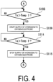
- FIGS. 3 and 4 are flowcharts illustrating a control operation during activation of the hydrogen production system 100.
- FIG. 5 is a graph illustrating an example of a relationship between the temperature of the electrolysis module 19 and the gas concentration at the inlet of the base body tube 14 (hydrogen electrode 11) during activation of the electrolysis module 19, and the temperature of the electrolysis module 19 and the timing of performing each control operation during the activation.
- step S101 the control device 80 controls to start the supply of air into the base body tube 14 (hydrogen electrode 11) and the oxygen electrode 12.
- the control device 80 controls the regulation unit 50 to open the air regulator valve 54 and the air-side discharge amount regulator valve 55 and close the steam regulator valve 51, the hydrogen regulator valve 52, and the hydrogen regulator valve (or gate valve) 53.
- the control device 80 performs control such that the air regulator valve 57 is in the open state and the hydrogen supply valve 31 and the hydrogen supply valve 56 are in the closed state.
- the air supplied from the air supply unit 70 to the oxygen electrode 12 heats the oxygen electrode 12, heats the entire electrolysis module 19 and the base body tube 14, and is discharged to the outside.
- the air supply pipe (heating medium supply system) 72 is a system that supplies air from the air supply unit 70 to the hydrogen electrode 11.
- the air supplied from the air supply unit 70 into the base body tube 14 via the air supply pipe 72 heats the base body tube 14, heats the entire electrolysis module 19 including the hydrogen electrode 11, and is discharged to the outside via the air discharge pipe 73.
- step S102 the control device 80 determines whether a temperature Ta of the electrolysis module 19 detected by the temperature sensor 17 exceeds Temp1 (first switching temperature), and advances the process to step S103 in response to the temperature Ta exceeding Temp1.
- Temp1 is set to a temperature higher than a dew point of steam at the hydrogen electrode 11 so that the steam does not condense into drain water internally.
- Temp1 is a temperature of, for example, 150°C or higher and 200°C or lower.
- Temp2 described below is set to a temperature higher than Temp1.
- the temperature of the electrolysis module 19 gradually increases.
- the time at which the temperature of the electrolysis module 19 reaches Temp1 is defined as time t1.
- the gas concentration at the inlet of the base body tube 14 is maintained at 100% air from the start of the activation of the hydrogen production system 100 until time t1.
- step S103 the control device 80 starts a closing operation of the air regulator valve 54 from the open state so as to stop the supply of air from the air supply unit 70 into the base body tube 14 (hydrogen electrode 11).
- step S104 the control device 80 starts an opening operation of the steam regulator valve 51 from the closed state so as to start the supply of steam from the steam supply unit 20 to the hydrogen electrode 11.
- the control device 80 controls the regulation unit 50 to shift from a state (heated air supply state) in which air is supplied from the air supply unit 70 into the base body tube 14 and steam is not supplied from the steam supply unit 20 into the base body tube 14 to a state (steam supply state) in which air is not supplied into the base body tube 14 and steam is supplied from the steam supply unit 20, thereby completing oxygen purging on the hydrogen electrode 11 side (second control step).
- step S105 the control device 80 determines whether the temperature Ta of the electrolysis module 19 detected by the temperature sensor 17 exceeds Temp2 (second switching temperature), and advances the process to step S107 when the temperature Ta exceeds Temp2.
- Temp2 is a temperature lower than a temperature at which a metal component included in the hydrogen electrode 11 is oxidized.
- Temp2 is a temperature of, for example, 350°C or higher and 400°C or lower.
- Temp2 is set to be lower than a temperature at which a rate at which a metal component included in the hydrogen electrode 11 reacts with steam and is oxidized considerably increases.
- the temperature of the electrolysis module 19 gradually increases due to the air on the oxygen electrode 12 side and the high-temperature steam in the base body tube 14.
- the time at which the temperature of the electrolysis module 19 reaches Temp2 is defined as time t2.
- the supply of steam is started after time t1 to reduce the oxygen concentration in the air at the inlet of the hydrogen electrode 11 to 0% and to increase the steam concentration to 100%. Thereafter, until time t2, the gas concentration at the inlet of the base body tube 14 (hydrogen electrode 11) is maintained at 100% steam.
- step S106 the control device 80 starts the supply of hydrogen from the hydrogen storage facility 40 into the base body tube 14 (hydrogen electrode 11), and starts an opening operation of the hydrogen regulator valve 52 and the hydrogen regulator valve (or gate valve) 53 from the closed state so that the hydrogen concentration at the inlet of the base body tube 14 becomes a predetermined value.
- step S107 the control device 80 reduces the supply of steam from the steam supply unit 20 into the base body tube 14 (hydrogen electrode 11), and closes the steam regulator valve 51 from the open state so that the steam concentration at the inlet of the base body tube 14 becomes a predetermined value.
- the control device 80 controls the regulation unit 50 to switch from the steam supply state to a state in which hydrogen, a reducing gas, is mixed (third control step). Since the hydrogen electrode 11 is maintained in a reducing state by switching from the steam supply state to the state in which hydrogen, a reducing gas, is mixed, steam oxidation of the hydrogen electrode by oxygen contained in the steam is prevented.
- step S108 the control device 80 determines whether the temperature Ta of the electrolysis module 19 detected by the temperature sensor 17 exceeds Temp3, and advances the process to step S109 when the temperature Ta exceeds Temp3.
- Temp3 is a temperature of, for example, 400°C or higher and 500°C or lower.
- the time at which the temperature Ta of the electrolysis module 19 reaches Temp3 is defined as time t3.
- step S109 the control device 80 switches the hydrogen supply valve 56 from the closed state to the open state so as to start the supply of hydrogen from the hydrogen storage facility 40 to the oxygen electrode 12.
- the hydrogen supplied to the oxygen electrode 12 of the electrolysis module 19 is combusted through catalysis of the oxygen electrode 12 to raise the temperature of the oxygen electrode 12 side of the electrolysis module 19.
- step S110 the control device 80 determines whether the temperature Ta of the electrolysis module 19 detected by the temperature sensor 17 exceeds Temp4, and advances the process to step S111 when the temperature Ta exceeds Temp4.
- Temp4 is a temperature higher than a temperature at which the electrolysis module 19 can produce hydrogen through steam electrolysis, and is, for example, a temperature of 600°C or higher and 700°C or lower.
- the time at which the temperature Ta of the electrolysis module 19 reaches Temp4 is defined as time t4.
- step S111 the control device 80 increases the supply amount of steam from the steam supply unit 20 to the hydrogen electrode 11 so as to meet an electrolysis start condition.
- the control device 80 regulates a valve opening degree of the steam regulator valve 51 and also regulates an opening degree of the hydrogen regulator valve 52, which controls the supply amount of hydrogen from the hydrogen storage facility 40 to the hydrogen electrode 11, to ensure that the hydrogen concentration at the inlet of the base body tube 14 (hydrogen electrode 11) meets the electrolysis start condition.
- step S112 the control device 80 determines whether the temperature Ta of the electrolysis module 19 exceeds TempS, whether the hydrogen concentration at the inlet of the base body tube 14 (hydrogen electrode 11) and the amount of supplied steam meet the electrolysis start conditions, and whether the power supply is ready to start, and when all the conditions are satisfied, the control device 80 advances the process to step S113.
- step S113 the control device 80 starts the supply of power from the power supply unit 18 to the electrolysis module 19 and controls the power supply unit 18 to gradually increase an amount of current.
- the electrolysis module 19 to which power is supplied from the power supply unit 18 starts production of hydrogen and oxygen through steam electrolysis.
- the time at which power supply to the electrolysis module 19 is started is defined as time t5.
- the valve opening degree of the steam regulator valve 51 is regulated to control the supply amount of steam to the hydrogen electrode 11
- the opening degree of the hydrogen regulator valve 52 is regulated to control the hydrogen concentration at the inlet of the base body tube 14 (hydrogen electrode 11).
- step S114 the control device 80 determines whether the temperature Ta of the electrolysis module 19 detected by the temperature sensor 17 exceeds Temp6, or whether the amount of current supplied to the electrolysis module 19 exceeds a predetermined value, and when either condition is satisfied, the control device 80 advances the process to step S115.
- Temp6 is a temperature of, for example, 650°C or higher and 750°C or lower.
- the time at which the determination condition is satisfied is defined as time t6.
- step S116 it is determined whether the amount of current supplied to the electrolysis module 19 has reached a rated value, and when it is determined to be YES, the activation is completed at that point in time, and the electrolysis module 19 enters a rated operation state.
- the time at which the rated current is reached is defined as time t7.
- the control device 80 controls the steam regulator valve 51 and the hydrogen regulator valve 52 so that the supply amount of steam to the hydrogen electrode 11 and the hydrogen concentration at the inlet of the base body tube 14 (hydrogen electrode 11) become rated conditions.
- the opening degrees of the steam regulator valve 51 and the hydrogen regulator valve 52 may be controlled by a function of the amount of current.
- FIG. 6 is a flowchart illustrating an example of an operation of the hydrogen production system during stoppage.
- FIG. 7 is a graph illustrating an example of a relationship between the elapsed time and the gas concentration at the inlet of the base body tube 14 (hydrogen electrode 11), and the temperature of the electrolysis module 19 and the timing of performing each control operation, during stoppage of the electrolysis module 19.
- step S201 the control device 80 controls the power supply unit 18 to reduce the current to stop supplying power from the power supply unit 18 to the electrolysis module 19.
- step S202 the control device 80 determines whether the current has stopped, and advances the process to step S203 when the current becomes zero (0).
- step S203 the control device 80 starts adjusting the supply amount of hydrogen from the hydrogen storage facility 40 into the base body tube 14 (hydrogen electrode 11), and starts operating the hydrogen regulator valve 52 so as to set the hydrogen concentration to a predetermined value so that the inlet of the base body tube 14 becomes a reducing atmosphere.
- step S204 the control device 80 reduces the supply of steam from the steam supply unit 20 into the base body tube 14 (hydrogen electrode 11), and closes the steam regulator valve 51 so that the steam concentration at the inlet of the base body tube 14 becomes a predetermined value.
- step S205 the control device 80 determines whether the temperature Ta of the electrolysis module 19 detected by the temperature sensor 17 falls below Temp10 (fifth switching temperature), and advances the process to step S206 in response to the temperature Ta falling below Temp10.
- Temp10 is a temperature of, for example, 350°C or higher and 400°C or lower. Temp10 is set to be lower than a temperature at which a metal component included in the hydrogen electrode 11 reacts with steam and is oxidized.
- the stopping operation of the electrolysis module 19 is started at time t8, and the time at which the electrolysis current becomes zero (0) is defined as t9.
- the opening degree of the hydrogen regulator valve 52 is regulated to start adjusting the inlet gas in the base body tube 14 (hydrogen electrode 11) to a reducing atmosphere, the supply of steam from the steam supply unit 20 into the base body tube 14 (hydrogen electrode 11) is reduced, and the steam regulator valve 51 is closed so that the steam concentration at the inlet of the base body tube 14 becomes a predetermined value.
- the time at which the steam concentration at the inlet of the base body tube 14 becomes a predetermined value and adjustment to the reducing atmosphere is completed is defined as time t10. Since the electrolysis current gradually decreases in the period from time t8 to time t9 and the electrolysis current does not flow after t9, the heat generated by the Joule's heat of the electrolysis current decreases and disappears, and the temperature Ta of the electrolysis module 19 gradually decreases.
- the time at which the temperature Ta of the electrolysis module 19 reaches Temp10 is defined as time t11 (see FIG. 7 ).
- step S206 the control device 80 switches the hydrogen regulator valve 52 and the hydrogen regulator valve (or gate valve) 53 from the open state to the closed state so as to reduce and stop the supply of hydrogen from the hydrogen storage facility 40 to the hydrogen electrode 11.
- step S207 the control device 80 opens the steam regulator valve 51 so as to increase the supply of steam from the steam supply unit 20 to the hydrogen electrode 11.
- control device 80 in response to the temperature Ta of the electrolysis module 19 falling below Temp10 when stopping the electrolysis module 19, controls the regulation unit 50 to switch the state (hydrogen supply state) in which hydrogen is supplied from the hydrogen storage facility 40 to the hydrogen electrode 11 and steam is supplied from the steam supply unit 20 to the hydrogen electrode 11 within a range in which a reducing atmosphere is maintained to the state (steam supply state) in which hydrogen is not supplied from the hydrogen storage facility 40 to the hydrogen electrode 11 and steam is supplied from the steam supply unit 20 to the hydrogen electrode 11 (fifth control step).
- the hydrogen concentration at the inlet of the hydrogen electrode 11 decreases, and the steam concentration at the inlet of the hydrogen electrode 11 increases accordingly, so that the hydrogen concentration becomes 0% and the steam concentration becomes 100%.
- the electrolysis module 19 is cooled by the gas flowing through the base body tube 14 (hydrogen electrode 11) and the oxygen electrode 12, the temperature Ta gradually decreases, and the time at which the temperature Ta reaches Temp11 is defined as t12 (see FIG. 7 ).
- step S208 the control device 80 determines whether the temperature Ta of the electrolysis module 19 detected by the temperature sensor 17 falls below Temp11 (sixth switching temperature), and advances the process to step S209 in response to the temperature Ta falling below Temp11.
- Temp11 is a temperature higher than the dew point of steam at the hydrogen electrode 11.
- Temp11 is a temperature of, for example, 150°C or higher and 200°C or lower.
- step S209 the control device 80 switches the air-side discharge amount regulator valve 55 from the closed state to the open state, switches the hydrogen supply valve 31 from the open state to the closed state, and switches the air regulator valve 54 from the closed state to the open state so as to start the supply of air from the air supply unit 70 to the hydrogen electrode 11.
- step S210 the control device 80 switches the steam regulator valve 51 from the open state to the closed state so as to stop the supply of steam from the steam supply unit 20 to the hydrogen electrode 11.
- control device 80 in response to the temperature Ta of the electrolysis module 19 falling below Temp11 when stopping the electrolysis module 19, controls the regulation unit 50 to switch the state (steam supply state) in which air is not supplied from the air supply unit 70 to the hydrogen electrode 11 and steam is supplied from the steam supply unit 20 to the hydrogen electrode 11 to the state (heating medium supply state) in which air is supplied from the air supply unit 70 to the hydrogen electrode 11 and steam is not supplied from the steam supply unit 20 to the hydrogen electrode 11 (sixth control step).
- the steam concentration at the inlet of the hydrogen electrode 11 decreases, and the air concentration at the inlet of the hydrogen electrode 11 increases, so that the steam concentration decreases to about atmospheric humidity and the air concentration reaches 100%. Since the temperature of the supplied air is lower than that of the steam in the system, the temperature Ta of the electrolysis module 19 gradually decreases.
- the time at which the temperature Ta reaches Temp12 is defined as time t13 (see FIG. 7 ).
- step S211 the control device 80 determines whether the temperature Ta of the electrolysis module 19 detected by the temperature sensor 17 falls below Temp12, and advances the process to step S212 in response to the temperature Ta falling below Temp12.
- Temp12 is a temperature of, for example, 50°C or lower.
- step S212 the control device 80 controls the regulation unit 50 to stop the supply of air to the hydrogen electrode 11 and the oxygen electrode 12.
- the control device 80 controls the air regulator valve 54 and the air-side discharge amount regulator valve 55 to be in the closed state. Further, the control device 80 controls the air regulator valve 57 to be in the closed state.
- the electrolysis module 19 electrolyzes steam supplied from the steam supply unit 20 to the hydrogen electrode 11, thereby generating hydrogen, which is stored in the hydrogen storage facility 40.
- the electrolysis module 19 When operating the electrolysis module 19, it is necessary to raise the temperature of the electrolysis module 19 to a temperature sufficient for steam electrolysis.
- oxygen contained in the steam water molecules causes steam oxidation of the metal component included in the hydrogen electrode 11, and this tendency becomes more pronounced as the temperature increases.
- air is supplied from the air supply unit 70 to the hydrogen electrode 11 to increase the temperature of the electrolysis module 19 to a temperature equal to or lower than the first switching temperature (Temp 1).
- the regulation unit 50 is controlled to switch the air supply state to the steam supply state.
- the control device 80 controls the regulation unit 50 to switch from the steam supply state to the state in which hydrogen, a reducing gas, is mixed, in order to prevent steam oxidation.
- the hydrogen electrode 11 is brought into a reducing atmosphere, so steam oxidation of the hydrogen electrode caused by oxygen contained in the steam is prevented.
- the state in which hydrogen is supplied from the hydrogen storage facility 40 to the hydrogen electrode 11 is switched to the state in which hydrogen is not supplied to the hydrogen electrode 11 and steam is supplied from the steam supply unit 20 to the hydrogen electrode 11. Since hydrogen of the hydrogen electrode 11 is replaced with steam before air is supplied to the hydrogen electrode 11, occurrence of abnormal combustion or the like caused by mixing of air and hydrogen can be appropriately prevented.
- the hydrogen production system 100 of the present embodiment in response to the electrolysis module 19 falling below Temp11, which is lower than Temp10, the state in which air is not supplied from the air supply unit 70 to the hydrogen electrode 11 and steam is supplied from the steam supply unit 20 to the hydrogen electrode 11 is switched to the state in which air is supplied from the air supply unit 70 to the hydrogen electrode 11 and steam is not supplied from the steam supply unit 20 to the hydrogen electrode 11. Therefore, as compared with a case where the steam of the hydrogen electrode 11 is replaced with air at a temperature equal to or higher than Temp11, the hydrogen electrode 11 is less likely to be oxidized, and the hydrogen electrode 11 can be prevented from being damaged.
- Temp2 and Temp10 are lower than the temperature at which the metal component included in the hydrogen electrode 11 is oxidized, it is possible to reliably prevent the hydrogen electrode 11 from being oxidized and damaged.
- the hydrogen production system 100A of the present embodiment is a modification example of the hydrogen production system 100 of the first embodiment and has the same configuration as that of the first embodiment unless otherwise described below.
- the hydrogen production system 100A according to the present embodiment is different from the hydrogen production system 100 according to the first embodiment, in that it includes a diverging pipe 34 that causes hydrogen to diverge from the hydrogen discharge pipe 33 to the hydrogen supply pipe 42, and a recirculation blower 44 arranged in the diverging pipe 34.
- step S106 of the first embodiment the control device 80 opens the hydrogen regulator valve 52 and switches the hydrogen regulator valve (or the gate valve) 53 from the closed state to the open state so as to start the supply of hydrogen from the hydrogen storage facility 40 to the hydrogen electrode 11.
- the open state of the hydrogen regulator valve 52 is maintained even after step S106.
- the control device 80 of the present embodiment switches the hydrogen regulator valve 52 from the open state to the closed state in response to a desired amount of hydrogen being supplied from the hydrogen storage facility 40 to the hydrogen supply pipe 42.
- the control device 80 of the present embodiment operates the recirculation blower 44 to guide the hydrogen supplied from the hydrogen electrode 11 to the hydrogen discharge pipe 33 to the hydrogen supply pipe 42 via the diverging pipe 34.
- the hydrogen guided to the hydrogen supply pipe 42 is supplied to the hydrogen electrode 11 again.
- hydrogen circulates through the hydrogen discharge pipe 33, the diverging pipe 34, the hydrogen supply pipe 42, the steam supply pipe 21, and the hydrogen electrode 11 in this order.
- the amount of hydrogen supplied to the hydrogen electrode 11 is controlled by flow rate control of the recirculation blower 44.
- the hydrogen production system 100A of the present embodiment when there is no need to change the flow rate and composition of the gas caused to flow through the base body tube 14 (hydrogen electrode 11) before the start of electrolysis, the entire amount of hydrogen supplied from the hydrogen electrode 11 to the hydrogen discharging pipe 33 is guided to the hydrogen electrode 11 again, and therefore there is no need to pass through the hydrogen separation facility 30 and the hydrogen storage facility 40. Therefore, power for cooling hydrogen and removing steam in the hydrogen separation facility 30 and power for heating hydrogen in the hydrogen storage facility 40 and supplying the hydrogen to the hydrogen supply pipe 42 are not required. Therefore, it is possible to reduce the power required to activate the hydrogen production system 100A.
- the hydrogen production system 100B of the present embodiment is a modification example of the hydrogen production system 100A of the second embodiment and has the same configuration as that of the second embodiment unless otherwise described below. As illustrated in FIG. 9 , the hydrogen production system 100B of the present embodiment is different from the hydrogen production system 100A of the second embodiment, in that it includes a hydrogen treatment facility 75 and a hydrogen concentration meter 76 in the heating medium discharge system of the electrolysis module 19.
- the electrolysis module 19 has a structure in which hydrogen generated in the hydrogen electrode 11 or supplied to the hydrogen electrode 11 is not directly mixed with the heating medium (air) on the oxygen electrode 12 side, but hydrogen may leak from the hydrogen electrode 11 side to the oxygen electrode 12 side. Therefore, in the present embodiment, a treatment is performed so that hydrogen leaking from the hydrogen electrode 11 side to the oxygen electrode 12 side is not mixed with air discharged from the oxygen electrode 12 to the outside and is not discharged to the outside air.
- the hydrogen treatment facility 75 is a facility that oxidizes mixed hydrogen to chemically change it into harmless water.
- An example of the hydrogen treatment facility 75 is a facility that has a hydrogen combustion catalyst therein and combusts hydrogen mixed in the air discharged from the oxygen electrode 12 and the air discharge pipe 73 by a catalytic reaction.
- the hydrogen concentration meter 76 is a device that detects the concentration of hydrogen mixed in the air discharged from the oxygen electrode 12 and the air discharge pipe 73. When a measured value of the hydrogen concentration detected by the hydrogen concentration meter 76 exceeds a predetermined threshold concentration, the control device 80 causes the hydrogen treatment facility 75 to oxidize hydrogen mixed in the discharged air, chemically changing the hydrogen into harmless water.
- FIG. 9 illustrates an example in which both the hydrogen treatment facility 75 and the hydrogen concentration meter 76 are provided, only the hydrogen concentration meter 76 may be provided without providing the hydrogen treatment facility 75.
- the control device 80 increases the flow rate of air supplied to the oxygen electrode 12 by the air supply unit 70 so as to reduce the hydrogen concentration in the air that is discharged to the outside.
- the control device 80 may reduce the current supplied to the electrolysis module so as to reduce the hydrogen concentration in the air that is discharged to the outside.
- the predetermined threshold concentration is preferably set, for example, to one-fourth of the lower explosive limit concentration of hydrogen in the atmosphere.
- control device 80 may perform control to stop the operation of the hydrogen production system 100B.
- the control device 80 may determine that an abnormality such as hydrogen leakage or damage to the electrolysis module 19 has occurred, and perform control to stop the operation of the hydrogen production system 100B.
- another temperature sensor may be provided at the inlet of the hydrogen treatment facility 75 or inside the hydrogen treatment facility 75, and when a temperature detected by this temperature sensor exceeds a predetermined threshold temperature, it may be determined that an abnormality such as hydrogen leakage or damage to the electrolysis module 19 has occurred, and control to stop the operation of the hydrogen production system 100B may be performed.
- the hydrogen production system 1 which has been described in each of the embodiments described above, is understood as follows, for example.
- a hydrogen production system (100) includes: an electrolysis module (19) including a hydrogen electrode (11), an oxygen electrode (12), and an electrolyte layer (13) arranged between the hydrogen electrode and the oxygen electrode, the electrolysis module (19) being configured to supply steam to the hydrogen electrode and produce hydrogen through steam electrolysis; a steam supply unit (20) configured to supply the steam to the hydrogen electrode; a hydrogen supply unit (40) configured to supply the hydrogen to the hydrogen electrode; a heating medium supply unit (70) configured to supply a heating medium to the oxygen electrode; a heating medium system (72) configured to supply the heating medium from the heating medium supply unit to the hydrogen electrode; and a hydrogen system (43) configured to supply the hydrogen from the hydrogen supply unit to the oxygen electrode.
- hydrogen is produced as the electrolysis module performs steam electrolysis on steam supplied from the steam supply unit.
- steam is supplied from the steam supply unit to the hydrogen electrode in order to increase the temperature of the electrolysis module to a temperature sufficient for performing steam electrolysis on steam.
- the metal component included in the hydrogen electrode is steam-oxidized by oxygen contained in the steam (water molecules), and this tendency becomes more pronounced as the temperature increases.
- steam present at the hydrogen electrode is replaced with hydrogen through the supply of hydrogen from the hydrogen supply unit to the hydrogen electrode. Therefore, oxidation of the hydrogen electrode caused by oxygen contained in the steam can be prevented.
- the hydrogen production system is the hydrogen production system of the first aspect further including the following configuration. That is, the hydrogen supply unit stores the hydrogen produced by the electrolysis module and supplies the hydrogen to the hydrogen electrode and the oxygen electrode.
- hydrogen used to prevent oxidation of the hydrogen electrode is supplied to the hydrogen electrode from the hydrogen supply unit that stores hydrogen produced by the electrolysis module. Therefore, as compared with a case where a separate facility is provided to supply an inert gas such as nitrogen gas so as to prevent oxidation of the hydrogen electrode, the operation cost when producing the inert gas is not increased.
- the hydrogen production system is the hydrogen production system of the first or second aspect further including the following configuration. That is, there is provided a regulation unit (50) configured to regulate a supply amount of the hydrogen supplied from the hydrogen supply unit to the hydrogen electrode, a supply amount of the hydrogen supplied from the hydrogen supply unit to the oxygen electrode, a supply amount of the steam supplied from the steam supply unit to the hydrogen electrode, a supply amount of the heating medium supplied from the heating medium supply unit to the oxygen electrode, and a supply amount of the heating medium supplied from the heating medium supply unit to the hydrogen electrode.
- a regulation unit 50 configured to regulate a supply amount of the hydrogen supplied from the hydrogen supply unit to the hydrogen electrode, a supply amount of the hydrogen supplied from the hydrogen supply unit to the oxygen electrode, a supply amount of the steam supplied from the steam supply unit to the hydrogen electrode, a supply amount of the heating medium supplied from the heating medium supply unit to the oxygen electrode, and a supply amount of the heating medium supplied from the heating medium supply unit to the hydrogen electrode.
- the supply amount of hydrogen supplied to the hydrogen electrode, the supply amount of hydrogen supplied to the oxygen electrode, the supply amount of steam supplied to the hydrogen electrode, the supply amount of heating medium supplied to the oxygen electrode, and the supply amount of heating medium supplied to the hydrogen electrode are regulated by the regulation unit, enabling appropriate production of hydrogen through steam electrolysis while preventing damage to the hydrogen electrode.
- the hydrogen production system is the hydrogen production system of the third aspect further including the following configuration. That is, when activating the electrolysis module, the regulation unit, in response to the electrolysis module exceeding a first switching temperature (Temp1), switches a state in which the heating medium is supplied from the heating medium supply unit to the hydrogen electrode and the steam is not supplied from the steam supply unit to the hydrogen electrode to a state in which the heating medium is not supplied from the heating medium supply unit to the hydrogen electrode and the steam is supplied from the steam supply unit to the hydrogen electrode.
- a first switching temperature Temp1
- the heating medium present at the hydrogen electrode is replaced with steam in response to the electrolysis module exceeding the first switching temperature. Since the heating medium is replaced with steam before hydrogen is supplied to the hydrogen electrode, for example, when the heating medium is a medium (air or the like) containing oxygen, occurrence of abnormal combustion or the like caused by mixing of the heating medium and hydrogen can be appropriately prevented.
- the hydrogen production system is the hydrogen production system of the fourth aspect further including the following configuration. That is, when activating the electrolysis module, the regulation unit, in response to the electrolysis module exceeding a second switching temperature (Temp2) higher than the first switching temperature, switches a state in which the hydrogen is not supplied from the hydrogen supply unit to the hydrogen electrode to a state in which the hydrogen is supplied from the hydrogen supply unit to the hydrogen electrode.
- a second switching temperature Tempo2
- the hydrogen production system is the hydrogen production system of the fifth aspect further including the following configuration. That is, when activating the electrolysis module, the regulation unit, in response to the electrolysis module exceeding a third switching temperature (Temp3), switches a state in which the hydrogen is not supplied to the oxygen electrode via the hydrogen system to a state in which the hydrogen is supplied to the oxygen electrode via the hydrogen system.
- a third switching temperature Tempo3
- hydrogen is supplied to the oxygen electrode in response to the electrolysis module exceeding the third switching temperature, the hydrogen is combusted through catalysis of the oxygen electrode, the temperature on the oxygen electrode side of the electrolysis module can be increased, and the temperature of the entire electrolysis module can be raised.
- the hydrogen production system is the hydrogen production system of the sixth aspect further including the following configuration. That is, when activating the electrolysis module, the regulation unit, in response to the electrolysis module exceeding a fourth switching temperature (Temp4) higher than the third switching temperature, increases the supply amount of the steam supplied from the steam supply unit to the hydrogen electrode.
- a fourth switching temperature Tempo4
- the state in which hydrogen is supplied from the hydrogen supply unit to the hydrogen electrode can be switched to the state in which hydrogen is not supplied to the hydrogen electrode, in response to the electrolysis module falling below the fifth switching temperature. Since hydrogen of the hydrogen electrode is replaced with another medium before the heating medium is supplied to the hydrogen electrode, for example, when the heating medium is a medium (air or the like) containing oxygen, occurrence of abnormal combustion or the like caused by mixing of the heating medium and hydrogen can be appropriately prevented.
- the hydrogen production system is the hydrogen production system of the eighth aspect wherein when stopping the electrolysis module, the regulation unit, in response to the electrolysis module falling below a sixth switching temperature (Temp11) lower than the fifth switching temperature, switches a state in which the heating medium is not supplied from the heating medium supply unit to the hydrogen electrode and the steam is supplied from the steam supply unit to the hydrogen electrode to a state in which the heating medium is supplied from the heating medium supply unit to the hydrogen electrode and the steam is not supplied from the steam supply unit to the hydrogen electrode.
- a sixth switching temperature Tempo11
- steam of the hydrogen electrode is replaced with the heating medium in response to the electrolysis module falling below the sixth switching temperature lower than the fifth switching temperature. Therefore, when oxygen is contained in the heating medium, the hydrogen electrode is less likely to be oxidized as compared with a case where steam of the hydrogen electrode is replaced with the heating medium at a temperature equal to or higher than the fifth switching temperature, and the hydrogen electrode can be prevented from being damaged.
- the hydrogen production system according to a tenth aspect of the present disclosure is the hydrogen production system of the fourth aspect, wherein the first switching temperature is a temperature higher than a dew point of the steam in the hydrogen electrode.
- the hydrogen production system according to an eleventh aspect of the present disclosure is the hydrogen production system of the ninth aspect, wherein the sixth switching temperature is a temperature higher than a dew point of the steam in the hydrogen electrode.
- the hydrogen production system according to a twelfth aspect of the present disclosure is the hydrogen production system of the fifth aspect, wherein the second switching temperature is a temperature lower than a temperature at which a metal component included in the hydrogen electrode is oxidized.
- the hydrogen production system according to a thirteenth aspect of the present disclosure is the hydrogen production system of the eighth aspect, wherein the fifth switching temperature is a temperature lower than a temperature at which a metal component included in the hydrogen electrode is oxidized.
- the hydrogen production system according to a fourteenth aspect of the present disclosure is the hydrogen production system of the seventh aspect, wherein the fourth switching temperature is a temperature higher than a temperature at which the electrolysis module can produce the hydrogen through the steam electrolysis.
- the amount of steam of the hydrogen electrode can be prevented from excessively increasing.
- the hydrogen production system is the hydrogen production system of the first or second aspect including a hydrogen concentration meter and a hydrogen treatment facility arranged in a heating medium discharge system of the electrolysis module.
- the hydrogen concentration can be detected by the hydrogen concentration meter arranged in the heating medium discharge system, and the hydrogen can be appropriately treated by the hydrogen treatment facility.
- the hydrogen production system includes: an electrolysis module including a hydrogen electrode including an metal component, an oxygen electrode, and an electrolyte layer arranged between the hydrogen electrode and the oxygen electrode, the electrolysis module being configured to supply steam to the hydrogen electrode and produce hydrogen through steam electrolysis; a steam supply unit configured to supply the steam to the hydrogen electrode; a hydrogen supply unit configured to supply the hydrogen to the hydrogen electrode; a heating medium supply unit configured to supply a heating medium to the oxygen electrode; a heating medium system configured to supply the heating medium from the heating medium supply unit to the hydrogen electrode; a hydrogen system configured to supply the hydrogen from the hydrogen supply unit to the oxygen electrode; and a regulation unit configured to regulate a supply amount of the hydrogen supplied from the hydrogen supply unit to the hydrogen electrode, a supply amount of the hydrogen supplied from the hydrogen supply unit to the oxygen electrode, a supply amount of the steam supplied from the steam supply unit to the hydrogen electrode, a supply amount of the heating medium supplied from the heating medium supply unit to the oxygen
- the first control step involves supplying steam supplied from the steam supply unit to the hydrogen electrode in response to the electrolysis module exceeding the first switching temperature, when activating the electrolysis module, thereby replacing the heating medium present at the hydrogen electrode with steam.
- the heating medium is a medium (air or the like) containing oxygen, oxidation of the hydrogen electrode caused by oxygen in the heating medium at a relatively low temperature higher than the first switching temperature can be prevented.
- the heating medium is replaced with steam before hydrogen is supplied to the hydrogen electrode, for example, when the heating medium is a medium (air or the like) containing oxygen, occurrence of abnormal combustion or the like caused by mixing of the heating medium and hydrogen can be appropriately prevented.
- the method for controlling the hydrogen production system of a seventeenth aspect of the present disclosure is the method of the sixteenth aspect including a second control step of, in response to the electrolysis module exceeding a second switching temperature higher than the first switching temperature when activating the electrolysis module, controlling the regulation unit to switch a state in which the hydrogen is not supplied from the hydrogen supply unit to the hydrogen electrode to a state in which the hydrogen is supplied from the hydrogen supply unit to the hydrogen electrode.
- steam present at the hydrogen electrode is replaced with hydrogen in response to the electrolysis module exceeding the second switching temperature. Since the steam present at the hydrogen electrode is gradually replaced with hydrogen, which is a reducing gas, bringing the hydrogen electrode into a reducing atmosphere, it is possible to appropriately prevent steam oxidation of the hydrogen electrode caused by oxygen contained in the steam.
- the method for controlling the hydrogen production system is the method of the seventeenth aspect including a third control step of, in response to the electrolysis module exceeding a third switching temperature when activating the electrolysis module, controlling the regulation unit to switch a state in which the hydrogen is not supplied to the oxygen electrode via the hydrogen system to a state in which the hydrogen is supplied to the oxygen electrode via the hydrogen system.
- hydrogen is supplied to the oxygen electrode in response to the electrolysis module exceeding the third switching temperature, the hydrogen is combusted through catalysis of the oxygen electrode, the temperature on the oxygen electrode side of the electrolysis module is increased, and the temperature of the entire electrolysis module can be raised.
- the method for controlling the hydrogen production system is the method of the eighteenth aspect including a fourth control step of, in response to the electrolysis module exceeding a fourth switching temperature higher than the third switching temperature when activating the electrolysis module, controlling the regulation unit to increase the supply amount of the steam supplied from the steam supply unit to the hydrogen electrode.
- the supply steam concentration can be adjusted to be suitable for the steam electrolysis reaction, and the steam electrolysis reaction can be appropriately performed.
- the method for controlling the hydrogen production system is the method of the seventeenth aspect including a fifth control step of, in response to the electrolysis module falling below the fifth switching temperature when stopping the electrolysis module, controlling the regulation unit to switch a state in which the hydrogen is supplied from the hydrogen supply unit to the hydrogen electrode to a state in which the hydrogen is not supplied from the hydrogen supply unit to the hydrogen electrode.
- the state in which hydrogen is supplied from the hydrogen supply unit is switched to the state in which hydrogen is not supplied to the hydrogen electrode, in response to the electrolysis module falling below the fifth switching temperature. Therefore, since hydrogen of the hydrogen electrode is replaced with another medium before the heating medium is supplied to the hydrogen electrode, for example, when the heating medium is a medium (air or the like) containing oxygen, occurrence of abnormal combustion or the like caused by mixing of the heating medium and hydrogen can be appropriately prevented.
- the method for controlling the hydrogen production system is the method of the twentieth aspect including a sixth control step of, in response to the electrolysis module falling below a sixth switching temperature lower than the fifth switching temperature when stopping the electrolysis module, controlling the regulation unit to switch a state in which the heating medium is not supplied from the heating medium supply unit to the hydrogen electrode and the steam is supplied from the steam supply unit to the hydrogen electrode to a state in which the heating medium is supplied from the heating medium supply unit to the hydrogen electrode and the steam is not supplied from the steam supply unit to the hydrogen electrode.
- steam of the hydrogen electrode is replaced with the heating medium in response to the electrolysis module falling below the sixth switching temperature lower than the fifth switching temperature. Therefore, when oxygen is contained in the heating medium, the hydrogen electrode is less likely to be oxidized as compared with a case where steam of the hydrogen electrode is replaced with the heating medium at a temperature equal to or higher than the fifth switching temperature, and the hydrogen electrode can be prevented from being damaged.
- the medium flowing through the electrolysis module is only the heating medium, and even when the electrolysis module is cooled and the temperature decreases, it is possible to prevent condensation of steam inside the electrolysis module.
Landscapes
- Chemical & Material Sciences (AREA)
- Engineering & Computer Science (AREA)
- Chemical Kinetics & Catalysis (AREA)
- Electrochemistry (AREA)
- Materials Engineering (AREA)
- Metallurgy (AREA)
- Organic Chemistry (AREA)
- Automation & Control Theory (AREA)
- Inorganic Chemistry (AREA)
- Analytical Chemistry (AREA)
- Electrolytic Production Of Non-Metals, Compounds, Apparatuses Therefor (AREA)
Abstract
Description
- The present disclosure relates to a hydrogen production system and a method for controlling the hydrogen production system.
- In the related art, a device for manufacturing hydrogen through steam electrolysis is known (for example, see Patent Document 1).
Patent Document 1 relates to a device including a solid oxide electrolysis cell (SOEC), and discloses recovering reaction heat of a fuel cell, which generates electric power using hydrogen produced in the SOEC, in a heat storage device and heating steam to be supplied to the SOEC. - Patent Document 1:
JP 2019-173082 A - A hydrogen electrode of a cell stack of the SOEC includes a metal material having electron conductivity, for example, nickel (Ni). At high temperatures of 400°C or higher, most nickel is oxidized in an oxidizing atmosphere to become nickel oxide, and the cell stack may be damaged due to volume expansion. To prevent the hydrogen electrode from being oxidized at high temperatures of 400°C or higher, it is necessary to maintain the hydrogen electrode in a reducing atmosphere, and for example, a method of filling a system of the hydrogen electrode with an inert gas such as nitrogen gas may be considered. However, to this end, an inert gas supply facility and energy for manufacturing are required, leading to an increase in operation cost when producing hydrogen.
- The present disclosure has been made in view of such circumstances, and an object of the present disclosure is to provide a hydrogen production system and a method for controlling the hydrogen production system capable of preventing a hydrogen electrode from being damaged without increasing an operation cost when producing hydrogen.
- In order to solve the above-described problem, the present disclosure employs the following means.
- A hydrogen production system according to the present disclosure includes: an electrolysis module being an assembly of electrolysis cells including a hydrogen electrode, an oxygen electrode, and an electrolyte layer arranged between the hydrogen electrode and the oxygen electrode, the electrolysis module being configured to supply steam to the hydrogen electrode and produce hydrogen through steam electrolysis; a steam supply unit configured to supply the steam to the hydrogen electrode; a hydrogen supply unit configured to supply the hydrogen to the hydrogen electrode; a heating medium supply unit configured to supply a heating medium to the oxygen electrode; a heating medium system configured to supply the heating medium from the heating medium supply unit to the hydrogen electrode; and a hydrogen system configured to supply the hydrogen from the hydrogen supply unit to the oxygen electrode.
- In a method for controlling a hydrogen production system, the hydrogen production system includes: an electrolysis module including a hydrogen electrode, an oxygen electrode, and an electrolyte layer arranged between the hydrogen electrode and the oxygen electrode, the electrolysis module being configured to supply steam to the hydrogen electrode and produce hydrogen through steam electrolysis; a steam supply unit configured to supply the steam to the hydrogen electrode; a hydrogen supply unit configured to supply the hydrogen to the hydrogen electrode; a heating medium supply unit configured to supply a heating medium to the oxygen electrode; a heating medium system configured to supply the heating medium from the heating medium supply unit to the hydrogen electrode; a hydrogen system configured to supply the hydrogen from the hydrogen supply unit to the oxygen electrode; and a regulation unit configured to regulate a supply amount of the hydrogen supplied from the hydrogen supply unit to the hydrogen electrode, a supply amount of the hydrogen supplied from the hydrogen supply unit to the oxygen electrode, a supply amount of the steam supplied from the steam supply unit to the hydrogen electrode, a supply amount of the heating medium supplied from the heating medium supply unit to the oxygen electrode, and a supply amount of the heating medium supplied from the heating medium supply unit to the hydrogen electrode, the method includes a first control step of, in response to the electrolysis module exceeding a first switching temperature when activating the electrolysis module, controlling the regulation unit to switch a state in which the heating medium is supplied from the heating medium supply unit to the hydrogen electrode and the steam is not supplied from the steam supply unit to the hydrogen electrode to a state in which the heating medium is not supplied from the heating medium supply unit to the hydrogen electrode and the steam is supplied from the steam supply unit to the hydrogen electrode.
- According to the present disclosure, it is possible to provide a hydrogen production system and a method for controlling the hydrogen production system capable of preventing a hydrogen electrode from being damaged without increasing an operation cost of activating the hydrogen production system.
-
-
FIG. 1 is a diagram illustrating a schematic configuration of a hydrogen production system according to a first embodiment of the present disclosure. -
FIG. 2 is a partial cross-sectional view illustrating an example of a cylindrical electrolysis module according to the first embodiment of the present disclosure. -
FIG. 3 is a flowchart illustrating an operation during activation of the hydrogen production system. -
FIG. 4 is a flowchart illustrating the operation during activation of the hydrogen production system. -
FIG. 5 is a graph illustrating an example of a relationship among the elapsed time, the temperature of an electrolysis cell, and the gas concentration at the inlet of a base body tube (hydrogen electrode) during activation of the electrolysis module, and the temperature of the electrolysis cell and the timing of performing each control operation during the activation. -
FIG. 6 is a flowchart illustrating an example of an operation of the hydrogen production system during stoppage. -
FIG. 7 is a graph illustrating an example of a relationship among the elapsed time, the temperature of the electrolysis cell, and the gas concentration at the inlet of the base body tube (hydrogen electrode) during stoppage of the electrolysis module, and the temperature of the electrolysis cell and the timing of performing each control operation during the stoppage. -
FIG. 8 is a diagram illustrating a schematic configuration of a hydrogen production system according to a second embodiment of the present disclosure. -
FIG. 9 is a diagram illustrating a schematic configuration of a hydrogen production system according to a third embodiment of the present disclosure. - A
hydrogen production system 100 according to a first embodiment of the present disclosure will be described below with reference toFIG. 1. FIG. 1 is a diagram illustrating a schematic configuration of ahydrogen production system 100 according to a first embodiment of the present disclosure. As illustrated inFIG. 1 , thehydrogen production system 100 of the present embodiment includes anelectrolysis module 19, apower supply unit 18, asteam supply unit 20, ahydrogen separation facility 30, a hydrogen storage facility (hydrogen supply unit) 40, aregulation unit 50, an air supply unit (heating medium supply unit) 70, and acontrol device 80. Note that although the present disclosure illustrates the system including the hydrogen storage facility (hydrogen supply unit), the hydrogen storage facility (hydrogen supply unit) 40 may be a hydrogen pipeline, and hydrogen may be taken out from the pipeline and supplied to the present system, or generated hydrogen may be directly supplied to the hydrogen pipeline. - A solid oxide electrolysis cell (hereinafter referred to as an electrolysis cell) 10 is an element constituting the
electrolysis module 19 that supplies steam supplied from thesteam supply unit 20 to ahydrogen electrode 11 and produces hydrogen and oxygen through steam electrolysis, and includes thehydrogen electrode 11, anoxygen electrode 12, and anelectrolyte layer 13 arranged between thehydrogen electrode 11 and theoxygen electrode 12. Theelectrolysis module 19 is an assembly ofelectrolysis cells 10. Steam electrolysis is a reverse reaction of a fuel cell that generates power, and theelectrolysis cell 10 can use substantially the same configuration and materials as those of a solid oxide fuel cell (SOFC). -
FIG. 1 schematically illustrates the relationship among theelectrolysis module 19, theelectrolysis cell 10, thehydrogen electrode 11, theoxygen electrode 12, and theelectrolyte layer 13. As the solid oxide electrolysis module 19 (hereinafter referred to as the electrolysis module 19), for example, a cylindrical cell stack can be used in which thehydrogen electrode 11 is arranged in a cylindrical tube body made of a porous material, theelectrolyte layer 13 is arranged on thehydrogen electrode 11, and theoxygen electrode 12 is arranged on theelectrolyte layer 13. Theelectrolysis module 19 also includes atemperature sensor 17 for measuring an operation temperature. -
FIG. 2 is a partial cross-sectional view illustrating an example of thecylindrical electrolysis module 19 according to the present embodiment. As an example, theelectrolysis module 19 is formed on a cylindricalbase body tube 14 and a plurality of locations on an outer peripheral surface of thebase body tube 14. Aninterconnector 15 is formed between theadjacent electrolysis modules 19. Theelectrolysis module 19 is formed by stacking thehydrogen electrode 11, theelectrolyte layer 13, and theoxygen electrode 12 on the surface of thebase body tube 14. - A
lead film 16 electrically connected via theinterconnector 15 to theoxygen electrode 12 of anelectrolysis module 19 formed at one end of the outermost edge in an axial direction of thebase body tube 14 among the plurality ofelectrolysis modules 19 formed on the outer peripheral surface of thebase body tube 14 is provided, and alead film 16 electrically connected to thehydrogen electrode 11 of anelectrolysis module 19 formed at the other end of the outermost edge is provided. Note that, in the following description, "supplying a medium (air, steam, hydrogen, or the like) to thehydrogen electrode 11" refers to supplying the medium to thehydrogen electrode 11, which is formed on the outer peripheral surface of thebase body tube 14, by causing the medium to flow through an inner space of thebase body tube 14 and diffuse into pores of thebase body tube 14. - The
base body tube 14 is made of a porous material and includes, for example, CaO-stabilized ZrO2 (CSZ), a mixture of CSZ and nickel oxide (NiO) (CSZ + NiO), Y2O3-stabilized ZrO2 (YSZ), MgAl2O4, or the like as a main component. Thebase body tube 14 supports theelectrolysis module 19, theinterconnector 15, and thelead film 16, and diffuses the steam supplied to an inner peripheral surface of thebase body tube 14 to thehydrogen electrode 11 formed on the outer peripheral surface of thebase body tube 14 through the pores of thebase body tube 14. - The
hydrogen electrode 11 is made of an oxide of a composite material of a metal material (for example, Ni or the like) and a zirconia-based electrolyte material, and for example, Ni/YSZ is used. Theoxygen electrode 12 is made of, for example, LaSrMnO3-based oxide or LaCoO3-based oxide. As theelectrolyte layer 13, YSZ is mainly used which has gas tightness and high oxygen ion conductivity at high temperatures. - The
interconnector 15 is made of, for example, a conductive perovskite-type oxide represented by M1-xLxTiO3 (M is an alkaline earth metal element, and L is a lanthanoid element) such as SrTiO3-based oxide. Theinterconnector 15 is in the form of a dense film so that steam and air (oxidizing gas) do not mix. - In addition, the
interconnector 15 has stable durability and electrical conductivity in both an oxidizing atmosphere and a reducing atmosphere. Theinterconnector 15 electrically connects theoxygen electrode 12 of oneelectrolysis module 19 and thehydrogen electrode 11 of theother electrolysis module 19 in theadjacent electrolysis modules 19, and connects theadjacent electrolysis modules 19 in series. - The
lead film 16 has electron conductivity and is made of a composite material of Ni and a zirconia-based electrolyte material, such as Ni/YSZ, or M1-xLxTiO3 such as SrTiO3-based material (M is an alkaline earth metal and L is a lanthanoid element). Thelead film 16 supplies DC power to the plurality ofelectrolysis modules 19 connected in series through theinterconnector 15. - When power is supplied from the outside between the
hydrogen electrode 11 and theoxygen electrode 12 via thelead film 16, part of the high-temperature steam supplied to thehydrogen electrode 11 accepts electrons, separates into hydrogen and oxygen ions, and produces hydrogen. The separated oxygen ions migrate inside theelectrolyte layer 13 to theoxygen electrode 12, release electrons, and produce oxygen. - The
temperature sensor 17 is a sensor that detects a temperature of the electrolysis module 19 (a temperature of theelectrolysis cell 10 itself or an ambient temperature of the space in which theelectrolysis cell 10 is arranged). The temperature of theelectrolysis module 19 detected by thetemperature sensor 17 is transmitted to thecontrol device 80. - The
power supply unit 18 is a device that supplies power for performing steam electrolysis to theelectrolysis module 19. A state of power supply from thepower supply unit 18 to theelectrolysis module 19 is controlled by thecontrol device 80. - The
steam supply unit 20 is a device that produces steam and supplies the steam to theelectrolysis module 19. The steam is supplied to thehydrogen electrode 11 of theelectrolysis module 19 through asteam supply pipe 21. The temperature of the hydrogen electrode inlet gas supplied to thehydrogen electrode 11 is, for example, 400°C or higher. - The
hydrogen separation facility 30 is a facility that separates hydrogen from the mixed gas of hydrogen and steam produced at thehydrogen electrode 11 of theelectrolysis module 19. When ahydrogen supply valve 31 is opened, hydrogen produced at thehydrogen electrode 11 is supplied to thehydrogen separation facility 30 via ahydrogen discharge pipe 33. The hydrogen separated by thehydrogen separation facility 30 is supplied to thehydrogen storage facility 40 by ahydrogen booster 32. Thehydrogen separation facility 30 cools the mixed gas of hydrogen and steam supplied from thehydrogen discharge pipe 33, for example, and condenses the steam contained in the mixed gas to recover it as recovered water. - The
hydrogen storage facility 40 is a facility that stores hydrogen generated by theelectrolysis module 19 and supplies hydrogen to a hydrogen supply destination via ahydrogen supply pipe 41. In addition, thehydrogen storage facility 40 can supply hydrogen to thehydrogen electrode 11 via ahydrogen supply pipe 42 and thesteam supply pipe 21. Additionally, thehydrogen storage facility 40 can supply hydrogen to theoxygen electrode 12 of theelectrolysis module 19 via a hydrogen supply pipe (hydrogen system) 43. The hydrogen supplied from thehydrogen storage facility 40 to thehydrogen electrode 11 is preferably heated in the process of flowing through thehydrogen supply pipe 42 and supplied to thesteam supply pipe 21 in order to maintain thehydrogen electrode 11 at a desired temperature. - The
regulation unit 50 is a device that regulates a supply amount of steam supplied from thesteam supply unit 20, a supply amount of hydrogen supplied from thehydrogen storage facility 40 to thehydrogen electrode 11, a supply amount of hydrogen supplied from thehydrogen storage facility 40 to theoxygen electrode 12, a supply amount of air supplied from theair supply unit 70 to theoxygen electrode 12, and a supply amount of air supplied from theair supply unit 70 to thehydrogen electrode 11. - The
regulation unit 50 includes asteam regulator valve 51 arranged in thesteam supply pipe 21, ahydrogen regulator valve 52 arranged in thehydrogen supply pipe 42, a hydrogen regulator valve (or gate valve) 53 arranged at a position close to thesteam supply pipe 21 on a downstream side of thehydrogen supply pipe 42, anair regulator valve 54 arranged in anair supply pipe 72, an air-side dischargeamount regulator valve 55 for hydrogen electrode vent gas arranged in anair discharge pipe 73, ahydrogen supply valve 56, and anair regulator valve 57. - The
hydrogen regulator valve 53 is a valve that is closed when steam is supplied to the hydrogen electrode but hydrogen is not supplied. By closing thehydrogen regulator valve 53, it is possible to prevent steam from entering thehydrogen supply pipe 42 when steam is supplied to the hydrogen electrode but hydrogen is not supplied. - The
hydrogen supply valve 56 is a valve that regulates a supply amount of hydrogen supplied from thehydrogen storage facility 40 to theoxygen electrode 12 via thehydrogen supply pipe 43 and theair supply pipe 74. The hydrogen supplied to theair supply pipe 74 is supplied to theoxygen electrode 12 side of theelectrolysis module 19. The hydrogen supplied to theoxygen electrode 12 of theelectrolysis module 19 and theoxygen electrode 12 side of thebase body tube 14 is combusted through catalysis to raise the temperature of theelectrolysis module 19. - In the
hydrogen production system 100 illustrated inFIG. 1 , hydrogen stored in thehydrogen storage facility 40 is supplied to theoxygen electrode 12 and theoxygen electrode 12 side of thebase body tube 14 by opening thehydrogen supply valve 56, but another mode may also be employed. For example, a fuel supply unit (not illustrated) that supplies hydrogen or another fuel gas (methane gas or the like) may be provided, and the fuel gas may be supplied from the fuel supply unit to theoxygen electrode 12 side of theelectrolysis module 19 and combusted through catalysis. - The
air supply unit 70 is a device that supplies air heated to a high temperature (for example, lower than 400°C) to theoxygen electrode 12 and thehydrogen electrode 11. The supply amount of air supplied from theair supply unit 70 to theoxygen electrode 12 and thehydrogen electrode 11 is regulated by theair regulator valve 57. The supply amount of air supplied from theair supply unit 70 to thehydrogen electrode 11 is regulated by theair regulator valve 54. - The
control device 80 is a device that controls thehydrogen production system 100. Thecontrol device 80 includes a storage unit (not illustrated) that stores a control program and a computation unit (not illustrated) that executes the program, and executes various operations for controlling thehydrogen production system 100 by executing the program read from the storage unit by the computation unit. - Next, a control operation that is executed by the
control device 80 of the present embodiment during activation of theelectrolysis module 19 will be described.FIGS. 3 and4 are flowcharts illustrating a control operation during activation of thehydrogen production system 100.FIG. 5 is a graph illustrating an example of a relationship between the temperature of theelectrolysis module 19 and the gas concentration at the inlet of the base body tube 14 (hydrogen electrode 11) during activation of theelectrolysis module 19, and the temperature of theelectrolysis module 19 and the timing of performing each control operation during the activation. - In step S101, the
control device 80 controls to start the supply of air into the base body tube 14 (hydrogen electrode 11) and theoxygen electrode 12. Thecontrol device 80 controls theregulation unit 50 to open theair regulator valve 54 and the air-side dischargeamount regulator valve 55 and close thesteam regulator valve 51, thehydrogen regulator valve 52, and the hydrogen regulator valve (or gate valve) 53. In addition, thecontrol device 80 performs control such that theair regulator valve 57 is in the open state and thehydrogen supply valve 31 and thehydrogen supply valve 56 are in the closed state. - The air supplied from the
air supply unit 70 to theoxygen electrode 12 heats theoxygen electrode 12, heats theentire electrolysis module 19 and thebase body tube 14, and is discharged to the outside. The air supply pipe (heating medium supply system) 72 is a system that supplies air from theair supply unit 70 to thehydrogen electrode 11. The air supplied from theair supply unit 70 into thebase body tube 14 via theair supply pipe 72 heats thebase body tube 14, heats theentire electrolysis module 19 including thehydrogen electrode 11, and is discharged to the outside via theair discharge pipe 73. - In step S102, the
control device 80 determines whether a temperature Ta of theelectrolysis module 19 detected by thetemperature sensor 17 exceeds Temp1 (first switching temperature), and advances the process to step S103 in response to the temperature Ta exceeding Temp1. Temp1 is set to a temperature higher than a dew point of steam at thehydrogen electrode 11 so that the steam does not condense into drain water internally. Temp1 is a temperature of, for example, 150°C or higher and 200°C or lower. Temp2 described below is set to a temperature higher than Temp1. - As illustrated in
FIG. 5 , when activation of thehydrogen production system 100 is started at time t0, the temperature of theelectrolysis module 19 gradually increases. The time at which the temperature of theelectrolysis module 19 reaches Temp1 is defined as time t1. As illustrated inFIG. 5 , the gas concentration at the inlet of thebase body tube 14 is maintained at 100% air from the start of the activation of thehydrogen production system 100 until time t1. - In step S103, the
control device 80 starts a closing operation of theair regulator valve 54 from the open state so as to stop the supply of air from theair supply unit 70 into the base body tube 14 (hydrogen electrode 11). - Subsequently, in step S104, the
control device 80 starts an opening operation of thesteam regulator valve 51 from the closed state so as to start the supply of steam from thesteam supply unit 20 to thehydrogen electrode 11. - As described above, when the temperature Ta of the
electrolysis module 19 exceeds Temp1 during activation of thehydrogen production system 100, thecontrol device 80 controls theregulation unit 50 to shift from a state (heated air supply state) in which air is supplied from theair supply unit 70 into thebase body tube 14 and steam is not supplied from thesteam supply unit 20 into thebase body tube 14 to a state (steam supply state) in which air is not supplied into thebase body tube 14 and steam is supplied from thesteam supply unit 20, thereby completing oxygen purging on thehydrogen electrode 11 side (second control step). - In step S105, the
control device 80 determines whether the temperature Ta of theelectrolysis module 19 detected by thetemperature sensor 17 exceeds Temp2 (second switching temperature), and advances the process to step S107 when the temperature Ta exceeds Temp2. Temp2 is a temperature lower than a temperature at which a metal component included in thehydrogen electrode 11 is oxidized. Temp2 is a temperature of, for example, 350°C or higher and 400°C or lower. Temp2 is set to be lower than a temperature at which a rate at which a metal component included in thehydrogen electrode 11 reacts with steam and is oxidized considerably increases. - As illustrated in
FIG. 5 , when the supply of steam to theelectrolysis module 19 is started at time t1, the temperature of theelectrolysis module 19 gradually increases due to the air on theoxygen electrode 12 side and the high-temperature steam in thebase body tube 14. The time at which the temperature of theelectrolysis module 19 reaches Temp2 is defined as time t2. As illustrated inFIG. 5 , the supply of steam is started after time t1 to reduce the oxygen concentration in the air at the inlet of thehydrogen electrode 11 to 0% and to increase the steam concentration to 100%. Thereafter, until time t2, the gas concentration at the inlet of the base body tube 14 (hydrogen electrode 11) is maintained at 100% steam. - In step S106, the
control device 80 starts the supply of hydrogen from thehydrogen storage facility 40 into the base body tube 14 (hydrogen electrode 11), and starts an opening operation of thehydrogen regulator valve 52 and the hydrogen regulator valve (or gate valve) 53 from the closed state so that the hydrogen concentration at the inlet of thebase body tube 14 becomes a predetermined value. - Subsequently, in step S107, the
control device 80 reduces the supply of steam from thesteam supply unit 20 into the base body tube 14 (hydrogen electrode 11), and closes thesteam regulator valve 51 from the open state so that the steam concentration at the inlet of thebase body tube 14 becomes a predetermined value. - As described above, when the temperature Ta of the
electrolysis module 19 exceeds Temp2 during activation of thehydrogen production system 100, thecontrol device 80 controls theregulation unit 50 to switch from the steam supply state to a state in which hydrogen, a reducing gas, is mixed (third control step). Since thehydrogen electrode 11 is maintained in a reducing state by switching from the steam supply state to the state in which hydrogen, a reducing gas, is mixed, steam oxidation of the hydrogen electrode by oxygen contained in the steam is prevented. - In step S108, the
control device 80 determines whether the temperature Ta of theelectrolysis module 19 detected by thetemperature sensor 17 exceeds Temp3, and advances the process to step S109 when the temperature Ta exceeds Temp3. Temp3 is a temperature of, for example, 400°C or higher and 500°C or lower. Here, the time at which the temperature Ta of theelectrolysis module 19 reaches Temp3 is defined as time t3. - In step S109, the
control device 80 switches thehydrogen supply valve 56 from the closed state to the open state so as to start the supply of hydrogen from thehydrogen storage facility 40 to theoxygen electrode 12. The hydrogen supplied to theoxygen electrode 12 of theelectrolysis module 19 is combusted through catalysis of theoxygen electrode 12 to raise the temperature of theoxygen electrode 12 side of theelectrolysis module 19. - In step S110, the
control device 80 determines whether the temperature Ta of theelectrolysis module 19 detected by thetemperature sensor 17 exceeds Temp4, and advances the process to step S111 when the temperature Ta exceeds Temp4. Temp4 is a temperature higher than a temperature at which theelectrolysis module 19 can produce hydrogen through steam electrolysis, and is, for example, a temperature of 600°C or higher and 700°C or lower. Here, the time at which the temperature Ta of theelectrolysis module 19 reaches Temp4 is defined as time t4. - In step S111, the
control device 80 increases the supply amount of steam from thesteam supply unit 20 to thehydrogen electrode 11 so as to meet an electrolysis start condition. Thecontrol device 80 regulates a valve opening degree of thesteam regulator valve 51 and also regulates an opening degree of thehydrogen regulator valve 52, which controls the supply amount of hydrogen from thehydrogen storage facility 40 to thehydrogen electrode 11, to ensure that the hydrogen concentration at the inlet of the base body tube 14 (hydrogen electrode 11) meets the electrolysis start condition. - In step S112, the
control device 80 determines whether the temperature Ta of theelectrolysis module 19 exceeds TempS, whether the hydrogen concentration at the inlet of the base body tube 14 (hydrogen electrode 11) and the amount of supplied steam meet the electrolysis start conditions, and whether the power supply is ready to start, and when all the conditions are satisfied, thecontrol device 80 advances the process to step S113. - In step S113, the
control device 80 starts the supply of power from thepower supply unit 18 to theelectrolysis module 19 and controls thepower supply unit 18 to gradually increase an amount of current. Theelectrolysis module 19 to which power is supplied from thepower supply unit 18 starts production of hydrogen and oxygen through steam electrolysis. In step S113, the time at which power supply to theelectrolysis module 19 is started is defined as time t5. After time t5, the valve opening degree of thesteam regulator valve 51 is regulated to control the supply amount of steam to thehydrogen electrode 11, and the opening degree of thehydrogen regulator valve 52 is regulated to control the hydrogen concentration at the inlet of the base body tube 14 (hydrogen electrode 11). - In step S114, the
control device 80 determines whether the temperature Ta of theelectrolysis module 19 detected by thetemperature sensor 17 exceeds Temp6, or whether the amount of current supplied to theelectrolysis module 19 exceeds a predetermined value, and when either condition is satisfied, thecontrol device 80 advances the process to step S115. Temp6 is a temperature of, for example, 650°C or higher and 750°C or lower. Here, the time at which the determination condition is satisfied is defined as time t6. - Thereafter, in step S116, it is determined whether the amount of current supplied to the
electrolysis module 19 has reached a rated value, and when it is determined to be YES, the activation is completed at that point in time, and theelectrolysis module 19 enters a rated operation state. Here, the time at which the rated current is reached is defined as time t7. Note that before the amount of current reaches the rated value, thecontrol device 80 controls thesteam regulator valve 51 and thehydrogen regulator valve 52 so that the supply amount of steam to thehydrogen electrode 11 and the hydrogen concentration at the inlet of the base body tube 14 (hydrogen electrode 11) become rated conditions. Here, the opening degrees of thesteam regulator valve 51 and thehydrogen regulator valve 52 may be controlled by a function of the amount of current. - Next, an operation that is executed by the
control device 80 of the present embodiment during stoppage of theelectrolysis module 19 will be described.FIG. 6 is a flowchart illustrating an example of an operation of the hydrogen production system during stoppage.FIG. 7 is a graph illustrating an example of a relationship between the elapsed time and the gas concentration at the inlet of the base body tube 14 (hydrogen electrode 11), and the temperature of theelectrolysis module 19 and the timing of performing each control operation, during stoppage of theelectrolysis module 19. - In step S201, the
control device 80 controls thepower supply unit 18 to reduce the current to stop supplying power from thepower supply unit 18 to theelectrolysis module 19. - In step S202, the
control device 80 determines whether the current has stopped, and advances the process to step S203 when the current becomes zero (0). - In step S203, the
control device 80 starts adjusting the supply amount of hydrogen from thehydrogen storage facility 40 into the base body tube 14 (hydrogen electrode 11), and starts operating thehydrogen regulator valve 52 so as to set the hydrogen concentration to a predetermined value so that the inlet of thebase body tube 14 becomes a reducing atmosphere. - Subsequently, in step S204, the
control device 80 reduces the supply of steam from thesteam supply unit 20 into the base body tube 14 (hydrogen electrode 11), and closes thesteam regulator valve 51 so that the steam concentration at the inlet of thebase body tube 14 becomes a predetermined value. - In step S205, the
control device 80 determines whether the temperature Ta of theelectrolysis module 19 detected by thetemperature sensor 17 falls below Temp10 (fifth switching temperature), and advances the process to step S206 in response to the temperature Ta falling below Temp10. Temp10 is a temperature of, for example, 350°C or higher and 400°C or lower. Temp10 is set to be lower than a temperature at which a metal component included in thehydrogen electrode 11 reacts with steam and is oxidized. - As illustrated in
FIG. 7 , the stopping operation of theelectrolysis module 19 is started at time t8, and the time at which the electrolysis current becomes zero (0) is defined as t9. From time t9, the opening degree of thehydrogen regulator valve 52 is regulated to start adjusting the inlet gas in the base body tube 14 (hydrogen electrode 11) to a reducing atmosphere, the supply of steam from thesteam supply unit 20 into the base body tube 14 (hydrogen electrode 11) is reduced, and thesteam regulator valve 51 is closed so that the steam concentration at the inlet of thebase body tube 14 becomes a predetermined value. - The time at which the steam concentration at the inlet of the
base body tube 14 becomes a predetermined value and adjustment to the reducing atmosphere is completed is defined as time t10. Since the electrolysis current gradually decreases in the period from time t8 to time t9 and the electrolysis current does not flow after t9, the heat generated by the Joule's heat of the electrolysis current decreases and disappears, and the temperature Ta of theelectrolysis module 19 gradually decreases. The time at which the temperature Ta of theelectrolysis module 19 reaches Temp10 is defined as time t11 (seeFIG. 7 ). - In step S206, the
control device 80 switches thehydrogen regulator valve 52 and the hydrogen regulator valve (or gate valve) 53 from the open state to the closed state so as to reduce and stop the supply of hydrogen from thehydrogen storage facility 40 to thehydrogen electrode 11. - Subsequently, in step S207, the
control device 80 opens thesteam regulator valve 51 so as to increase the supply of steam from thesteam supply unit 20 to thehydrogen electrode 11. - As described above, the
control device 80, in response to the temperature Ta of theelectrolysis module 19 falling below Temp10 when stopping theelectrolysis module 19, controls theregulation unit 50 to switch the state (hydrogen supply state) in which hydrogen is supplied from thehydrogen storage facility 40 to thehydrogen electrode 11 and steam is supplied from thesteam supply unit 20 to thehydrogen electrode 11 within a range in which a reducing atmosphere is maintained to the state (steam supply state) in which hydrogen is not supplied from thehydrogen storage facility 40 to thehydrogen electrode 11 and steam is supplied from thesteam supply unit 20 to the hydrogen electrode 11 (fifth control step). - As illustrated in
FIG. 7 , after time t11, the hydrogen concentration at the inlet of thehydrogen electrode 11 decreases, and the steam concentration at the inlet of thehydrogen electrode 11 increases accordingly, so that the hydrogen concentration becomes 0% and the steam concentration becomes 100%. Theelectrolysis module 19 is cooled by the gas flowing through the base body tube 14 (hydrogen electrode 11) and theoxygen electrode 12, the temperature Ta gradually decreases, and the time at which the temperature Ta reaches Temp11 is defined as t12 (seeFIG. 7 ). - In step S208, the
control device 80 determines whether the temperature Ta of theelectrolysis module 19 detected by thetemperature sensor 17 falls below Temp11 (sixth switching temperature), and advances the process to step S209 in response to the temperature Ta falling below Temp11. Temp11 is a temperature higher than the dew point of steam at thehydrogen electrode 11. Temp11 is a temperature of, for example, 150°C or higher and 200°C or lower. - In step S209, the
control device 80 switches the air-side dischargeamount regulator valve 55 from the closed state to the open state, switches thehydrogen supply valve 31 from the open state to the closed state, and switches theair regulator valve 54 from the closed state to the open state so as to start the supply of air from theair supply unit 70 to thehydrogen electrode 11. - In step S210, the
control device 80 switches thesteam regulator valve 51 from the open state to the closed state so as to stop the supply of steam from thesteam supply unit 20 to thehydrogen electrode 11. - As described above, the
control device 80, in response to the temperature Ta of theelectrolysis module 19 falling below Temp11 when stopping theelectrolysis module 19, controls theregulation unit 50 to switch the state (steam supply state) in which air is not supplied from theair supply unit 70 to thehydrogen electrode 11 and steam is supplied from thesteam supply unit 20 to thehydrogen electrode 11 to the state (heating medium supply state) in which air is supplied from theair supply unit 70 to thehydrogen electrode 11 and steam is not supplied from thesteam supply unit 20 to the hydrogen electrode 11 (sixth control step). - As illustrated in
FIG. 7 , after time t12, the steam concentration at the inlet of thehydrogen electrode 11 decreases, and the air concentration at the inlet of thehydrogen electrode 11 increases, so that the steam concentration decreases to about atmospheric humidity and the air concentration reaches 100%. Since the temperature of the supplied air is lower than that of the steam in the system, the temperature Ta of theelectrolysis module 19 gradually decreases. The time at which the temperature Ta reaches Temp12 is defined as time t13 (seeFIG. 7 ). - In step S211, the
control device 80 determines whether the temperature Ta of theelectrolysis module 19 detected by thetemperature sensor 17 falls below Temp12, and advances the process to step S212 in response to the temperature Ta falling below Temp12. Temp12 is a temperature of, for example, 50°C or lower. - In step S212, the
control device 80 controls theregulation unit 50 to stop the supply of air to thehydrogen electrode 11 and theoxygen electrode 12. Thecontrol device 80 controls theair regulator valve 54 and the air-side dischargeamount regulator valve 55 to be in the closed state. Further, thecontrol device 80 controls theair regulator valve 57 to be in the closed state. By the above, thehydrogen production system 100 is brought into a stopped state. - The actions and effects exhibited by the
hydrogen production system 100 of the present embodiment described above will now be described. - According to the
hydrogen production system 100 of the present embodiment, theelectrolysis module 19 electrolyzes steam supplied from thesteam supply unit 20 to thehydrogen electrode 11, thereby generating hydrogen, which is stored in thehydrogen storage facility 40. When operating theelectrolysis module 19, it is necessary to raise the temperature of theelectrolysis module 19 to a temperature sufficient for steam electrolysis. However, during the temperature increase process of theelectrolysis module 19, if steam is supplied to thehydrogen electrode 11 without applying an electric current and the temperature is raised without performing steam electrolysis, oxygen contained in the steam (water molecules) causes steam oxidation of the metal component included in thehydrogen electrode 11, and this tendency becomes more pronounced as the temperature increases. - Therefore, first, air is supplied from the
air supply unit 70 to thehydrogen electrode 11 to increase the temperature of theelectrolysis module 19 to a temperature equal to or lower than the first switching temperature (Temp 1). When the temperature of theelectrolysis module 19 exceeds the first switching temperature (Temp1), theregulation unit 50 is controlled to switch the air supply state to the steam supply state. By switching at a temperature exceeding the first switching temperature, it is possible to prevent the supplied steam from condensing into drain water in the electrolysis module, thereby preventing corrosion of thehydrogen electrode 11 and the metal part of the electrolysis module. - Then, hydrogen is supplied to the
hydrogen electrode 11. When the temperature of theelectrolysis module 19 exceeds the second switching temperature (Temp2), thecontrol device 80 controls theregulation unit 50 to switch from the steam supply state to the state in which hydrogen, a reducing gas, is mixed, in order to prevent steam oxidation. By switching from the steam supply state to the hydrogen-mixed state, thehydrogen electrode 11 is brought into a reducing atmosphere, so steam oxidation of the hydrogen electrode caused by oxygen contained in the steam is prevented. - Therefore, it is possible to prevent the
hydrogen electrode 11 including the metal component from being damaged as compared with a case where the steam supply state is not switched to the state in which the reducing hydrogen is mixed. In addition, hydrogen used for preventing oxidation of thehydrogen electrode 11 is supplied to thehydrogen electrode 11 from thehydrogen storage facility 40 that stores hydrogen produced by theelectrolysis module 19, and the supplied hydrogen is recovered again by the hydrogen separation facility. - Therefore, as compared with a case where a facility for supplying nitrogen gas or the like in order to prevent oxidation of the
hydrogen electrode 11 is separately provided, it is possible to reduce the facility cost and the operation cost when producing hydrogen. Further, since oxygen is not present by replacing air in the vent gas flow path of thehydrogen electrode 11 with steam at the time of mixing hydrogen, safety can be secured. - According to the
hydrogen production system 100 of the present embodiment, in response to theelectrolysis module 19 falling below Temp10, the state in which hydrogen is supplied from thehydrogen storage facility 40 to thehydrogen electrode 11 is switched to the state in which hydrogen is not supplied to thehydrogen electrode 11 and steam is supplied from thesteam supply unit 20 to thehydrogen electrode 11. Since hydrogen of thehydrogen electrode 11 is replaced with steam before air is supplied to thehydrogen electrode 11, occurrence of abnormal combustion or the like caused by mixing of air and hydrogen can be appropriately prevented. - According to the
hydrogen production system 100 of the present embodiment, in response to theelectrolysis module 19 falling below Temp11, which is lower than Temp10, the state in which air is not supplied from theair supply unit 70 to thehydrogen electrode 11 and steam is supplied from thesteam supply unit 20 to thehydrogen electrode 11 is switched to the state in which air is supplied from theair supply unit 70 to thehydrogen electrode 11 and steam is not supplied from thesteam supply unit 20 to thehydrogen electrode 11. Therefore, as compared with a case where the steam of thehydrogen electrode 11 is replaced with air at a temperature equal to or higher than Temp11, thehydrogen electrode 11 is less likely to be oxidized, and thehydrogen electrode 11 can be prevented from being damaged. - According to the
hydrogen production system 100 of the present embodiment, since Temp2 and Temp10 are lower than the temperature at which the metal component included in thehydrogen electrode 11 is oxidized, it is possible to reliably prevent thehydrogen electrode 11 from being oxidized and damaged. - Next, a
hydrogen production system 100A according to a second embodiment of the present disclosure will be described. Thehydrogen production system 100A of the present embodiment is a modification example of thehydrogen production system 100 of the first embodiment and has the same configuration as that of the first embodiment unless otherwise described below. - As illustrated in
FIG. 8 , thehydrogen production system 100A according to the present embodiment is different from thehydrogen production system 100 according to the first embodiment, in that it includes a divergingpipe 34 that causes hydrogen to diverge from thehydrogen discharge pipe 33 to thehydrogen supply pipe 42, and arecirculation blower 44 arranged in the divergingpipe 34. - The operation at the time of activation of the
hydrogen production system 100A of the present embodiment is different from the operation at the time of activation of thehydrogen production system 100 of the first embodiment in the operation of step S106 inFIG. 3 . In step S106 of the first embodiment, thecontrol device 80 opens thehydrogen regulator valve 52 and switches the hydrogen regulator valve (or the gate valve) 53 from the closed state to the open state so as to start the supply of hydrogen from thehydrogen storage facility 40 to thehydrogen electrode 11. In addition, the open state of thehydrogen regulator valve 52 is maintained even after step S106. - On the other hand, after switching the
hydrogen regulator valve 52 and thehydrogen regulator valve 53 from the closed state to the open state so as to start the supply of hydrogen from thehydrogen storage facility 40 to thehydrogen electrode 11, thecontrol device 80 of the present embodiment switches thehydrogen regulator valve 52 from the open state to the closed state in response to a desired amount of hydrogen being supplied from thehydrogen storage facility 40 to thehydrogen supply pipe 42. - In response to the start of hydrogen supply from the
hydrogen storage facility 40 to thehydrogen electrode 11, thecontrol device 80 of the present embodiment operates therecirculation blower 44 to guide the hydrogen supplied from thehydrogen electrode 11 to thehydrogen discharge pipe 33 to thehydrogen supply pipe 42 via the divergingpipe 34. The hydrogen guided to thehydrogen supply pipe 42 is supplied to thehydrogen electrode 11 again. In this way, by operating therecirculation blower 44, hydrogen circulates through thehydrogen discharge pipe 33, the divergingpipe 34, thehydrogen supply pipe 42, thesteam supply pipe 21, and thehydrogen electrode 11 in this order. At this time, the amount of hydrogen supplied to thehydrogen electrode 11 is controlled by flow rate control of therecirculation blower 44. - According to the
hydrogen production system 100A of the present embodiment, when there is no need to change the flow rate and composition of the gas caused to flow through the base body tube 14 (hydrogen electrode 11) before the start of electrolysis, the entire amount of hydrogen supplied from thehydrogen electrode 11 to thehydrogen discharging pipe 33 is guided to thehydrogen electrode 11 again, and therefore there is no need to pass through thehydrogen separation facility 30 and thehydrogen storage facility 40. Therefore, power for cooling hydrogen and removing steam in thehydrogen separation facility 30 and power for heating hydrogen in thehydrogen storage facility 40 and supplying the hydrogen to thehydrogen supply pipe 42 are not required. Therefore, it is possible to reduce the power required to activate thehydrogen production system 100A. - Next, a
hydrogen production system 100B according to a third embodiment of the present disclosure will be described. Thehydrogen production system 100B of the present embodiment is a modification example of thehydrogen production system 100A of the second embodiment and has the same configuration as that of the second embodiment unless otherwise described below. As illustrated inFIG. 9 , thehydrogen production system 100B of the present embodiment is different from thehydrogen production system 100A of the second embodiment, in that it includes ahydrogen treatment facility 75 and ahydrogen concentration meter 76 in the heating medium discharge system of theelectrolysis module 19. - The
electrolysis module 19 has a structure in which hydrogen generated in thehydrogen electrode 11 or supplied to thehydrogen electrode 11 is not directly mixed with the heating medium (air) on theoxygen electrode 12 side, but hydrogen may leak from thehydrogen electrode 11 side to theoxygen electrode 12 side. Therefore, in the present embodiment, a treatment is performed so that hydrogen leaking from thehydrogen electrode 11 side to theoxygen electrode 12 side is not mixed with air discharged from theoxygen electrode 12 to the outside and is not discharged to the outside air. - The
hydrogen treatment facility 75 is a facility that oxidizes mixed hydrogen to chemically change it into harmless water. An example of thehydrogen treatment facility 75 is a facility that has a hydrogen combustion catalyst therein and combusts hydrogen mixed in the air discharged from theoxygen electrode 12 and theair discharge pipe 73 by a catalytic reaction. - The
hydrogen concentration meter 76 is a device that detects the concentration of hydrogen mixed in the air discharged from theoxygen electrode 12 and theair discharge pipe 73. When a measured value of the hydrogen concentration detected by thehydrogen concentration meter 76 exceeds a predetermined threshold concentration, thecontrol device 80 causes thehydrogen treatment facility 75 to oxidize hydrogen mixed in the discharged air, chemically changing the hydrogen into harmless water. - Note that although
FIG. 9 illustrates an example in which both thehydrogen treatment facility 75 and thehydrogen concentration meter 76 are provided, only thehydrogen concentration meter 76 may be provided without providing thehydrogen treatment facility 75. In this case, when the hydrogen concentration detected by thehydrogen concentration meter 76 exceeds a predetermined threshold concentration, thecontrol device 80 increases the flow rate of air supplied to theoxygen electrode 12 by theair supply unit 70 so as to reduce the hydrogen concentration in the air that is discharged to the outside. - In addition, when the measured value of the hydrogen concentration detected by the
hydrogen concentration meter 76 exceeds a predetermined threshold concentration, thecontrol device 80 may reduce the current supplied to the electrolysis module so as to reduce the hydrogen concentration in the air that is discharged to the outside. In the above description, the predetermined threshold concentration is preferably set, for example, to one-fourth of the lower explosive limit concentration of hydrogen in the atmosphere. - Furthermore, when the
control device 80 determines that the measured value of the hydrogen concentration detected by thehydrogen concentration meter 76 is so high that increasing the flow rate of the air supplied to theoxygen electrode 12 by theair supply unit 70 cannot reduce the hydrogen concentration to a safe concentration, thecontrol device 80 may perform control to stop the operation of thehydrogen production system 100B. - In addition, in the present embodiment, when the temperature Ta of the
electrolysis module 19 detected by thetemperature sensor 17 exceeds a predetermined threshold temperature, thecontrol device 80 may determine that an abnormality such as hydrogen leakage or damage to theelectrolysis module 19 has occurred, and perform control to stop the operation of thehydrogen production system 100B. Additionally, instead of thetemperature sensor 17, another temperature sensor may be provided at the inlet of thehydrogen treatment facility 75 or inside thehydrogen treatment facility 75, and when a temperature detected by this temperature sensor exceeds a predetermined threshold temperature, it may be determined that an abnormality such as hydrogen leakage or damage to theelectrolysis module 19 has occurred, and control to stop the operation of thehydrogen production system 100B may be performed. - The
hydrogen production system 1, which has been described in each of the embodiments described above, is understood as follows, for example. - A hydrogen production system (100) according to a first aspect of the present disclosure includes: an electrolysis module (19) including a hydrogen electrode (11), an oxygen electrode (12), and an electrolyte layer (13) arranged between the hydrogen electrode and the oxygen electrode, the electrolysis module (19) being configured to supply steam to the hydrogen electrode and produce hydrogen through steam electrolysis; a steam supply unit (20) configured to supply the steam to the hydrogen electrode; a hydrogen supply unit (40) configured to supply the hydrogen to the hydrogen electrode; a heating medium supply unit (70) configured to supply a heating medium to the oxygen electrode; a heating medium system (72) configured to supply the heating medium from the heating medium supply unit to the hydrogen electrode; and a hydrogen system (43) configured to supply the hydrogen from the hydrogen supply unit to the oxygen electrode.
- With the hydrogen production system (100) according to the first aspect of the present disclosure, hydrogen is produced as the electrolysis module performs steam electrolysis on steam supplied from the steam supply unit. When activating the electrolysis module, steam is supplied from the steam supply unit to the hydrogen electrode in order to increase the temperature of the electrolysis module to a temperature sufficient for performing steam electrolysis on steam. As the temperature of the electrolysis module increases, the metal component included in the hydrogen electrode is steam-oxidized by oxygen contained in the steam (water molecules), and this tendency becomes more pronounced as the temperature increases. With the hydrogen production system according to the first aspect of the present disclosure, steam present at the hydrogen electrode is replaced with hydrogen through the supply of hydrogen from the hydrogen supply unit to the hydrogen electrode. Therefore, oxidation of the hydrogen electrode caused by oxygen contained in the steam can be prevented.
- The hydrogen production system according to a second aspect of the present disclosure is the hydrogen production system of the first aspect further including the following configuration. That is, the hydrogen supply unit stores the hydrogen produced by the electrolysis module and supplies the hydrogen to the hydrogen electrode and the oxygen electrode.
- With the hydrogen production system according to the second aspect of the present disclosure, hydrogen used to prevent oxidation of the hydrogen electrode is supplied to the hydrogen electrode from the hydrogen supply unit that stores hydrogen produced by the electrolysis module. Therefore, as compared with a case where a separate facility is provided to supply an inert gas such as nitrogen gas so as to prevent oxidation of the hydrogen electrode, the operation cost when producing the inert gas is not increased.
- The hydrogen production system according to a third aspect of the present disclosure is the hydrogen production system of the first or second aspect further including the following configuration. That is, there is provided a regulation unit (50) configured to regulate a supply amount of the hydrogen supplied from the hydrogen supply unit to the hydrogen electrode, a supply amount of the hydrogen supplied from the hydrogen supply unit to the oxygen electrode, a supply amount of the steam supplied from the steam supply unit to the hydrogen electrode, a supply amount of the heating medium supplied from the heating medium supply unit to the oxygen electrode, and a supply amount of the heating medium supplied from the heating medium supply unit to the hydrogen electrode.
- With the hydrogen production system according to the third aspect of the present disclosure, the supply amount of hydrogen supplied to the hydrogen electrode, the supply amount of hydrogen supplied to the oxygen electrode, the supply amount of steam supplied to the hydrogen electrode, the supply amount of heating medium supplied to the oxygen electrode, and the supply amount of heating medium supplied to the hydrogen electrode are regulated by the regulation unit, enabling appropriate production of hydrogen through steam electrolysis while preventing damage to the hydrogen electrode.
- The hydrogen production system according to a fourth aspect of the present disclosure is the hydrogen production system of the third aspect further including the following configuration. That is, when activating the electrolysis module, the regulation unit, in response to the electrolysis module exceeding a first switching temperature (Temp1), switches a state in which the heating medium is supplied from the heating medium supply unit to the hydrogen electrode and the steam is not supplied from the steam supply unit to the hydrogen electrode to a state in which the heating medium is not supplied from the heating medium supply unit to the hydrogen electrode and the steam is supplied from the steam supply unit to the hydrogen electrode.
- With the hydrogen production system according to the fourth aspect of the present disclosure, the heating medium present at the hydrogen electrode is replaced with steam in response to the electrolysis module exceeding the first switching temperature. Since the heating medium is replaced with steam before hydrogen is supplied to the hydrogen electrode, for example, when the heating medium is a medium (air or the like) containing oxygen, occurrence of abnormal combustion or the like caused by mixing of the heating medium and hydrogen can be appropriately prevented.
- The hydrogen production system according to a fifth aspect of the present disclosure is the hydrogen production system of the fourth aspect further including the following configuration. That is, when activating the electrolysis module, the regulation unit, in response to the electrolysis module exceeding a second switching temperature (Temp2) higher than the first switching temperature, switches a state in which the hydrogen is not supplied from the hydrogen supply unit to the hydrogen electrode to a state in which the hydrogen is supplied from the hydrogen supply unit to the hydrogen electrode.
- With the hydrogen production system according to the fifth aspect of the present disclosure, steam present at the hydrogen electrode is replaced with hydrogen in response to the electrolysis module exceeding the second switching temperature. Since the steam present at the hydrogen electrode is gradually replaced with hydrogen, which is a reducing gas, bringing the hydrogen electrode into a reducing atmosphere, it is possible to appropriately prevent steam oxidation of the hydrogen electrode caused by oxygen contained in the steam.
- The hydrogen production system according to a sixth aspect of the present disclosure is the hydrogen production system of the fifth aspect further including the following configuration. That is, when activating the electrolysis module, the regulation unit, in response to the electrolysis module exceeding a third switching temperature (Temp3), switches a state in which the hydrogen is not supplied to the oxygen electrode via the hydrogen system to a state in which the hydrogen is supplied to the oxygen electrode via the hydrogen system.
- With the hydrogen production system according to the sixth aspect of the present disclosure, hydrogen is supplied to the oxygen electrode in response to the electrolysis module exceeding the third switching temperature, the hydrogen is combusted through catalysis of the oxygen electrode, the temperature on the oxygen electrode side of the electrolysis module can be increased, and the temperature of the entire electrolysis module can be raised.
- The hydrogen production system according to a seventh aspect of the present disclosure is the hydrogen production system of the sixth aspect further including the following configuration. That is, when activating the electrolysis module, the regulation unit, in response to the electrolysis module exceeding a fourth switching temperature (Temp4) higher than the third switching temperature, increases the supply amount of the steam supplied from the steam supply unit to the hydrogen electrode.
- With the hydrogen production system according to the seventh aspect of the present disclosure, since the supply amount of the steam supplied to the hydrogen electrode increases in response to the electrolysis module exceeding the fourth switching temperature, it is possible to compensate for the steam reduced by the steam electrolysis reaction and appropriately promote the steam electrolysis reaction.
- The hydrogen production system according to an eighth aspect of the present disclosure is the hydrogen production system of the fifth aspect further including the following configuration. That is, when stopping the electrolysis module, the regulation unit, in response to the electrolysis module falling below the fifth switching temperature (Temp10), switches a state in which the hydrogen is supplied from the hydrogen supply unit to the hydrogen electrode to a state in which the hydrogen is not supplied from the hydrogen supply unit to the hydrogen electrode.
- With the hydrogen production system according to the eighth aspect of the present disclosure, the state in which hydrogen is supplied from the hydrogen supply unit to the hydrogen electrode can be switched to the state in which hydrogen is not supplied to the hydrogen electrode, in response to the electrolysis module falling below the fifth switching temperature. Since hydrogen of the hydrogen electrode is replaced with another medium before the heating medium is supplied to the hydrogen electrode, for example, when the heating medium is a medium (air or the like) containing oxygen, occurrence of abnormal combustion or the like caused by mixing of the heating medium and hydrogen can be appropriately prevented.
- The hydrogen production system according to a ninth aspect of the present disclosure is the hydrogen production system of the eighth aspect wherein when stopping the electrolysis module, the regulation unit, in response to the electrolysis module falling below a sixth switching temperature (Temp11) lower than the fifth switching temperature, switches a state in which the heating medium is not supplied from the heating medium supply unit to the hydrogen electrode and the steam is supplied from the steam supply unit to the hydrogen electrode to a state in which the heating medium is supplied from the heating medium supply unit to the hydrogen electrode and the steam is not supplied from the steam supply unit to the hydrogen electrode.
- With the hydrogen production system according to the ninth aspect of the present disclosure, steam of the hydrogen electrode is replaced with the heating medium in response to the electrolysis module falling below the sixth switching temperature lower than the fifth switching temperature. Therefore, when oxygen is contained in the heating medium, the hydrogen electrode is less likely to be oxidized as compared with a case where steam of the hydrogen electrode is replaced with the heating medium at a temperature equal to or higher than the fifth switching temperature, and the hydrogen electrode can be prevented from being damaged.
- The hydrogen production system according to a tenth aspect of the present disclosure is the hydrogen production system of the fourth aspect, wherein the first switching temperature is a temperature higher than a dew point of the steam in the hydrogen electrode. The hydrogen production system according to an eleventh aspect of the present disclosure is the hydrogen production system of the ninth aspect, wherein the sixth switching temperature is a temperature higher than a dew point of the steam in the hydrogen electrode.
- With the hydrogen production system according to the tenth aspect and the eleventh aspect of the present disclosure, since the first switching temperature and the sixth switching temperature are higher than the dew point of steam in the hydrogen electrode, steam supplied to the hydrogen electrode can be appropriately prevented from condensing to generate drain water.
- The hydrogen production system according to a twelfth aspect of the present disclosure is the hydrogen production system of the fifth aspect, wherein the second switching temperature is a temperature lower than a temperature at which a metal component included in the hydrogen electrode is oxidized.
- With the hydrogen production system according to the twelfth aspect of the present disclosure, steam is replaced with hydrogen at a temperature lower than a temperature at which the metal component included in the hydrogen electrode is oxidized. Therefore, the metal component included in the hydrogen electrode can be appropriately prevented from being oxidized by steam.
- The hydrogen production system according to a thirteenth aspect of the present disclosure is the hydrogen production system of the eighth aspect, wherein the fifth switching temperature is a temperature lower than a temperature at which a metal component included in the hydrogen electrode is oxidized.
- With the hydrogen production system according to the thirteenth aspect of the present disclosure, steam is replaced with hydrogen at a temperature lower than a temperature at which the metal component included in the hydrogen electrode is oxidized. Therefore, the metal component included in the hydrogen electrode can be appropriately prevented from being oxidized by steam.
- The hydrogen production system according to a fourteenth aspect of the present disclosure is the hydrogen production system of the seventh aspect, wherein the fourth switching temperature is a temperature higher than a temperature at which the electrolysis module can produce the hydrogen through the steam electrolysis.
- With the hydrogen production system according to the fourteenth aspect of the present disclosure, since the supply amount of steam is increased in response to the electrolysis module exceeding the fourth switching temperature higher than the temperature at which the electrolysis module can produce hydrogen through steam electrolysis, the amount of steam of the hydrogen electrode can be prevented from excessively increasing.
- The hydrogen production system according to a fifteenth aspect of the present disclosure is the hydrogen production system of the first or second aspect including a hydrogen concentration meter and a hydrogen treatment facility arranged in a heating medium discharge system of the electrolysis module.
- With the hydrogen production system according to the fifteenth aspect of the present disclosure, the hydrogen concentration can be detected by the hydrogen concentration meter arranged in the heating medium discharge system, and the hydrogen can be appropriately treated by the hydrogen treatment facility.
- In a method for controlling a hydrogen production system according to a sixteenth aspect of the present disclosure, the hydrogen production system includes: an electrolysis module including a hydrogen electrode including an metal component, an oxygen electrode, and an electrolyte layer arranged between the hydrogen electrode and the oxygen electrode, the electrolysis module being configured to supply steam to the hydrogen electrode and produce hydrogen through steam electrolysis; a steam supply unit configured to supply the steam to the hydrogen electrode; a hydrogen supply unit configured to supply the hydrogen to the hydrogen electrode; a heating medium supply unit configured to supply a heating medium to the oxygen electrode; a heating medium system configured to supply the heating medium from the heating medium supply unit to the hydrogen electrode; a hydrogen system configured to supply the hydrogen from the hydrogen supply unit to the oxygen electrode; and a regulation unit configured to regulate a supply amount of the hydrogen supplied from the hydrogen supply unit to the hydrogen electrode, a supply amount of the hydrogen supplied from the hydrogen supply unit to the oxygen electrode, a supply amount of the steam supplied from the steam supply unit to the hydrogen electrode, a supply amount of the heating medium supplied from the heating medium supply unit to the oxygen electrode, and a supply amount of the heating medium supplied from the heating medium supply unit to the hydrogen electrode, the method includes a first control step of, in response to the electrolysis module exceeding a first switching temperature when activating the electrolysis module, controlling the regulation unit to switch a state in which the heating medium is supplied from the heating medium supply unit to the hydrogen electrode and the steam is not supplied from the steam supply unit to the hydrogen electrode to a state in which the heating medium is not supplied from the heating medium supply unit to the hydrogen electrode and the steam is supplied from the steam supply unit to the hydrogen electrode.
- With the method for controlling the hydrogen production system according to the sixteenth aspect of the present disclosure, the first control step involves supplying steam supplied from the steam supply unit to the hydrogen electrode in response to the electrolysis module exceeding the first switching temperature, when activating the electrolysis module, thereby replacing the heating medium present at the hydrogen electrode with steam. Thus, when the heating medium is a medium (air or the like) containing oxygen, oxidation of the hydrogen electrode caused by oxygen in the heating medium at a relatively low temperature higher than the first switching temperature can be prevented.
- In addition, since the heating medium is replaced with steam before hydrogen is supplied to the hydrogen electrode, for example, when the heating medium is a medium (air or the like) containing oxygen, occurrence of abnormal combustion or the like caused by mixing of the heating medium and hydrogen can be appropriately prevented.
- The method for controlling the hydrogen production system of a seventeenth aspect of the present disclosure is the method of the sixteenth aspect including a second control step of, in response to the electrolysis module exceeding a second switching temperature higher than the first switching temperature when activating the electrolysis module, controlling the regulation unit to switch a state in which the hydrogen is not supplied from the hydrogen supply unit to the hydrogen electrode to a state in which the hydrogen is supplied from the hydrogen supply unit to the hydrogen electrode.
- With the method for controlling the hydrogen production system according to the seventeenth aspect of the present disclosure, steam present at the hydrogen electrode is replaced with hydrogen in response to the electrolysis module exceeding the second switching temperature. Since the steam present at the hydrogen electrode is gradually replaced with hydrogen, which is a reducing gas, bringing the hydrogen electrode into a reducing atmosphere, it is possible to appropriately prevent steam oxidation of the hydrogen electrode caused by oxygen contained in the steam.
- The method for controlling the hydrogen production system according to an eighteenth aspect of the present disclosure is the method of the seventeenth aspect including a third control step of, in response to the electrolysis module exceeding a third switching temperature when activating the electrolysis module, controlling the regulation unit to switch a state in which the hydrogen is not supplied to the oxygen electrode via the hydrogen system to a state in which the hydrogen is supplied to the oxygen electrode via the hydrogen system.
- With the method for controlling the hydrogen production system according to the eighteenth aspect of the present disclosure, hydrogen is supplied to the oxygen electrode in response to the electrolysis module exceeding the third switching temperature, the hydrogen is combusted through catalysis of the oxygen electrode, the temperature on the oxygen electrode side of the electrolysis module is increased, and the temperature of the entire electrolysis module can be raised.
- The method for controlling the hydrogen production system according to a nineteenth aspect of the present disclosure is the method of the eighteenth aspect including a fourth control step of, in response to the electrolysis module exceeding a fourth switching temperature higher than the third switching temperature when activating the electrolysis module, controlling the regulation unit to increase the supply amount of the steam supplied from the steam supply unit to the hydrogen electrode.
- With the method for controlling the hydrogen production system according to the nineteenth aspect of the present disclosure, since the supply amount of steam supplied to the hydrogen electrode increases in response to the electrolysis module exceeding the fourth switching temperature, the supply steam concentration can be adjusted to be suitable for the steam electrolysis reaction, and the steam electrolysis reaction can be appropriately performed.
- The method for controlling the hydrogen production system according to a twentieth aspect of the present disclosure is the method of the seventeenth aspect including a fifth control step of, in response to the electrolysis module falling below the fifth switching temperature when stopping the electrolysis module, controlling the regulation unit to switch a state in which the hydrogen is supplied from the hydrogen supply unit to the hydrogen electrode to a state in which the hydrogen is not supplied from the hydrogen supply unit to the hydrogen electrode.
- With the method for controlling the hydrogen production system according to the twentieth aspect of the present disclosure, the state in which hydrogen is supplied from the hydrogen supply unit is switched to the state in which hydrogen is not supplied to the hydrogen electrode, in response to the electrolysis module falling below the fifth switching temperature. Therefore, since hydrogen of the hydrogen electrode is replaced with another medium before the heating medium is supplied to the hydrogen electrode, for example, when the heating medium is a medium (air or the like) containing oxygen, occurrence of abnormal combustion or the like caused by mixing of the heating medium and hydrogen can be appropriately prevented.
- The method for controlling the hydrogen production system according to a twenty-first aspect of the present disclosure is the method of the twentieth aspect including a sixth control step of, in response to the electrolysis module falling below a sixth switching temperature lower than the fifth switching temperature when stopping the electrolysis module, controlling the regulation unit to switch a state in which the heating medium is not supplied from the heating medium supply unit to the hydrogen electrode and the steam is supplied from the steam supply unit to the hydrogen electrode to a state in which the heating medium is supplied from the heating medium supply unit to the hydrogen electrode and the steam is not supplied from the steam supply unit to the hydrogen electrode.
- With the method for controlling the hydrogen production system according to the twenty-first aspect of the present disclosure, steam of the hydrogen electrode is replaced with the heating medium in response to the electrolysis module falling below the sixth switching temperature lower than the fifth switching temperature. Therefore, when oxygen is contained in the heating medium, the hydrogen electrode is less likely to be oxidized as compared with a case where steam of the hydrogen electrode is replaced with the heating medium at a temperature equal to or higher than the fifth switching temperature, and the hydrogen electrode can be prevented from being damaged.
- In addition, with the method for controlling the hydrogen production system according to the twenty-first aspect of the present disclosure, the medium flowing through the electrolysis module is only the heating medium, and even when the electrolysis module is cooled and the temperature decreases, it is possible to prevent condensation of steam inside the electrolysis module.
-
- 10 Electrolysis cell
- 11 Hydrogen electrode
- 12 Oxygen electrode
- 13 Electrolyte layer
- 14 Base body tube
- 15 Interconnector
- 16 Lead film
- 17 Temperature sensor
- 18 Power supply unit
- 19 Electrolysis module
- 20 Steam supply unit
- 21 Steam supply pipe
- 30 Hydrogen separation facility
- 31 Hydrogen supply valve
- 32 Hydrogen booster
- 33 Hydrogen discharge pipe
- 34 Diverging pipe
- 40 Hydrogen storage facility (hydrogen supply unit)
- 41 Hydrogen supply pipe
- 42 Hydrogen supply pipe
- 43 Hydrogen supply pipe (hydrogen system)
- 44 Recirculation blower
- 50 Regulation unit
- 51 Steam regulator valve
- 52 Hydrogen regulator valve
- 53 Hydrogen regulator valve (or gate valve)
- 54 Air regulator valve
- 55 Air-side discharge amount regulator valve for hydrogen electrode vent gas
- 56 Hydrogen supply valve
- 57 Air regulator valve
- 70 Air supply unit
- 72 Air supply pipe (heating medium system)
- 73 Air discharge pipe
- 74 Air supply pipe
- 75 Hydrogen treatment facility
- 76 Hydrogen concentration meter
- 80 Control device (control unit)
- 100, 100A, 100B Hydrogen production system
- Ta Temperature of electrolysis module
Claims (25)
- A hydrogen production system comprising:an electrolysis module being an assembly of electrolysis cells comprising a hydrogen electrode, an oxygen electrode, and an electrolyte layer arranged between the hydrogen electrode and the oxygen electrode, the electrolysis module being configured to supply steam to the hydrogen electrode and produce hydrogen through steam electrolysis;a steam supply unit configured to supply the steam to the hydrogen electrode;a hydrogen supply unit configured to supply the hydrogen to the hydrogen electrode;a heating medium supply unit configured to supply a heating medium to the oxygen electrode;a heating medium system configured to supply the heating medium from the heating medium supply unit to the hydrogen electrode; anda hydrogen system configured to supply the hydrogen from the hydrogen supply unit to the oxygen electrode.
- The hydrogen production system according to claim 1, wherein the hydrogen supply unit stores the hydrogen produced by the electrolysis module and supplies the hydrogen to the hydrogen electrode and the oxygen electrode.
- The hydrogen production system according to claim 1 or 2, comprising a regulation unit configured to regulate a supply amount of the hydrogen supplied from the hydrogen supply unit to the hydrogen electrode, a supply amount of the hydrogen supplied from the hydrogen supply unit to the oxygen electrode, a supply amount of the steam supplied from the steam supply unit to the hydrogen electrode, a supply amount of the heating medium supplied from the heating medium supply unit to the oxygen electrode, and a supply amount of the heating medium supplied from the heating medium supply unit to the hydrogen electrode.
- The hydrogen production system according to claim 3, wherein when activating the electrolysis module, the regulation unit, in response to the electrolysis module exceeding a first switching temperature, a state in which the heating medium is supplied from the heating medium supply unit to the hydrogen electrode and the steam is not supplied from the steam supply unit to the hydrogen electrode to a state in which the heating medium is not supplied from the heating medium supply unit to the hydrogen electrode and the steam is supplied from the steam supply unit to the hydrogen electrode.
- The hydrogen production system according to claim 4, wherein when activating the electrolysis module, the regulation unit, in response to the electrolysis module exceeding a second switching temperature higher than the first switching temperature, switches a state in which the hydrogen is not supplied from the hydrogen supply unit to the hydrogen electrode to a state in which the hydrogen is supplied from the hydrogen supply unit to the hydrogen electrode.
- The hydrogen production system according to claim 5, wherein when activating the electrolysis module, the regulation unit, in response to the electrolysis module exceeding a third switching temperature, switches a state in which the hydrogen is not supplied to the oxygen electrode via the hydrogen system to a state in which the hydrogen is supplied to the oxygen electrode via the hydrogen system.
- The hydrogen production system according to claim 6, wherein when activating the electrolysis module, the regulation unit, in response to the electrolysis module exceeding a fourth switching temperature higher than the third switching temperature, increases the supply amount of the steam supplied from the steam supply unit to the hydrogen electrode.
- The hydrogen production system according to claim 5, wherein when stopping the electrolysis module, the regulation unit, in response to the electrolysis module falling below a fifth switching temperature, switches a state in which the hydrogen is supplied from the hydrogen supply unit to the hydrogen electrode to a state in which the hydrogen is not supplied from the hydrogen supply unit to the hydrogen electrode.
- The hydrogen production system according to claim 8, wherein when stopping the electrolysis module, the regulation unit, in response to the electrolysis module falling below a sixth switching temperature lower than the fifth switching temperature, switches a state in which the heating medium is not supplied from the heating medium supply unit to the hydrogen electrode and the steam is supplied from the steam supply unit to the hydrogen electrode to a state in which the heating medium is supplied from the heating medium supply unit to the hydrogen electrode and the steam is not supplied from the steam supply unit to the hydrogen electrode.
- The hydrogen production system according to claim 4, wherein the first switching temperature is a temperature higher than a dew point of the steam in the hydrogen electrode.
- The hydrogen production system according to claim 9, wherein the sixth switching temperature is a temperature higher than a dew point of the steam in the hydrogen electrode.
- The hydrogen production system according to claim 5, wherein the second switching temperature is a temperature lower than a temperature at which a metal component included in the hydrogen electrode is oxidized.
- The hydrogen production system according to claim 8, wherein the fifth switching temperature is a temperature lower than a temperature at which a metal component included in the hydrogen electrode is oxidized.
- The hydrogen production system according to claim 7, wherein the fourth switching temperature is a temperature higher than a temperature at which the electrolysis module can produce the hydrogen through the steam electrolysis.
- The hydrogen production system according to claim 1 or 2, comprising a hydrogen concentration meter and a hydrogen treatment facility arranged in a heating medium discharge system of the electrolysis module.
- A method for controlling a hydrogen production system, the hydrogen production system comprising:an electrolysis module comprising a hydrogen electrode, an oxygen electrode, and an electrolyte layer arranged between the hydrogen electrode and the oxygen electrode, the electrolysis module being configured to supply steam to the hydrogen electrode and produce hydrogen through steam electrolysis;a steam supply unit configured to supply the steam to the hydrogen electrode;a hydrogen supply unit configured to supply the hydrogen to the hydrogen electrode;a heating medium supply unit configured to supply a heating medium to the oxygen electrode;a heating medium system configured to supply the heating medium from the heating medium supply unit to the hydrogen electrode;a hydrogen system configured to supply the hydrogen from the hydrogen supply unit to the oxygen electrode; anda regulation unit configured to regulate a supply amount of the hydrogen supplied from the hydrogen supply unit to the hydrogen electrode, a supply amount of the hydrogen supplied from the hydrogen supply unit to the oxygen electrode, a supply amount of the steam supplied from the steam supply unit to the hydrogen electrode, a supply amount of the heating medium supplied from the heating medium supply unit to the oxygen electrode, and a supply amount of the heating medium supplied from the heating medium supply unit to the hydrogen electrode,the method comprising a first control step of, in response to the electrolysis module exceeding a first switching temperature when activating the electrolysis module, controlling the regulation unit to switch a state in which the heating medium is supplied from the heating medium supply unit to the hydrogen electrode and the steam is not supplied from the steam supply unit to the hydrogen electrode to a state in which the heating medium is not supplied from the heating medium supply unit to the hydrogen electrode and the steam is supplied from the steam supply unit to the hydrogen electrode.
- The method for controlling the hydrogen production system according to claim 16, comprising a second control step of, in response to the electrolysis module exceeding a second switching temperature higher than the first switching temperature when activating the electrolysis module, controlling the regulation unit to switch a state in which the hydrogen is not supplied from the hydrogen supply unit to the hydrogen electrode to a state in which the hydrogen is supplied from the hydrogen supply unit to the hydrogen electrode.
- The method for controlling the hydrogen production system according to claim 17, comprising a third control step of, in response to the electrolysis module exceeding a third switching temperature when activating the electrolysis module, controlling the regulation unit to switch a state in which the hydrogen is not supplied to the oxygen electrode via the hydrogen system to a state in which the hydrogen is supplied to the oxygen electrode via the hydrogen system.
- The method for controlling the hydrogen production system according to claim 18, comprising a fourth control step of, in response to the electrolysis module exceeding a fourth switching temperature higher than the third switching temperature when activating the electrolysis module, controlling the regulation unit to increase the supply amount of the steam supplied from the steam supply unit to the hydrogen electrode.
- The method for controlling the hydrogen production system according to claim 17, comprising a fifth control step of, in response to the electrolysis module falling below the fifth switching temperature when stopping the electrolysis module, controlling the regulation unit to switch a state in which the hydrogen is supplied from the hydrogen supply unit to the hydrogen electrode to a state in which the hydrogen is not supplied from the hydrogen supply unit to the hydrogen electrode.
- The method for controlling the hydrogen production system according to claim 20, comprising a sixth control step of, in response to the electrolysis module falling below a sixth switching temperature lower than the fifth switching temperature when stopping the electrolysis module, controlling the regulation unit to switch a state in which the heating medium is not supplied from the heating medium supply unit to the hydrogen electrode and the steam is supplied from the steam supply unit to the hydrogen electrode to a state in which the heating medium is supplied from the heating medium supply unit to the hydrogen electrode and the steam is not supplied from the steam supply unit to the hydrogen electrode.
- The method for controlling the hydrogen production system according to claim 16, comprising subjecting the hydrogen included in a heating medium discharge system of the electrolysis module to a combustion treatment by a hydrogen treatment facility arranged in the heating medium discharge system, in response to a measured value of a hydrogen concentration meter arranged in the heating medium discharge system exceeding a preset threshold concentration.
- The method for controlling the hydrogen production system according to claim 16, comprising reducing an amount of current supplied to the electrolysis module or stopping the current, in response to a measured value of a hydrogen concentration meter arranged in a heating medium discharge system of the electrolysis module exceeding a preset threshold concentration.
- The method for controlling the hydrogen production system according to claim 16, comprising increasing a supply amount of the heating medium supplied to the electrolysis module, in response to a measured value of a hydrogen concentration meter arranged in a heating medium discharge system of the electrolysis module exceeding a preset threshold concentration.
- The method for controlling the hydrogen production system according to any one of claims 22 to 24, comprising setting the threshold concentration to one-fourth of a lower explosive limit concentration of the hydrogen in the atmosphere.
Applications Claiming Priority (2)
| Application Number | Priority Date | Filing Date | Title |
|---|---|---|---|
| JP2022143636A JP7282968B1 (en) | 2022-09-09 | 2022-09-09 | Hydrogen generation system and method of controlling hydrogen generation system |
| PCT/JP2023/006936 WO2024053133A1 (en) | 2022-09-09 | 2023-02-27 | Hydrogen production system and method for controlling hydrogen production system |
Publications (2)
| Publication Number | Publication Date |
|---|---|
| EP4567158A1 true EP4567158A1 (en) | 2025-06-11 |
| EP4567158A4 EP4567158A4 (en) | 2025-12-10 |
Family
ID=86538286
Family Applications (1)
| Application Number | Title | Priority Date | Filing Date |
|---|---|---|---|
| EP23862683.2A Pending EP4567158A4 (en) | 2022-09-09 | 2023-02-27 | HYDROGEN PRODUCTION SYSTEM AND METHOD FOR CONTROLLING THE HYDROGEN PRODUCTION SYSTEM |
Country Status (6)
| Country | Link |
|---|---|
| US (1) | US20260071341A1 (en) |
| EP (1) | EP4567158A4 (en) |
| JP (1) | JP7282968B1 (en) |
| AU (1) | AU2023336295A1 (en) |
| TW (1) | TW202411473A (en) |
| WO (1) | WO2024053133A1 (en) |
Cited By (1)
| Publication number | Priority date | Publication date | Assignee | Title |
|---|---|---|---|---|
| WO2025253109A1 (en) * | 2024-06-04 | 2025-12-11 | Ceres Power Limited | Warm up method for an electrolyser system |
Families Citing this family (2)
| Publication number | Priority date | Publication date | Assignee | Title |
|---|---|---|---|---|
| JP7585530B1 (en) * | 2024-01-31 | 2024-11-18 | 三菱重工業株式会社 | Hydrogen generation system and method for controlling hydrogen generation system |
| JP2025119405A (en) * | 2024-02-01 | 2025-08-14 | 株式会社アイシン | water electrolysis device |
Family Cites Families (10)
| Publication number | Priority date | Publication date | Assignee | Title |
|---|---|---|---|---|
| US4801369A (en) * | 1987-06-29 | 1989-01-31 | Westinghouse Electric Corp. | Preventing fluids in leakable enclosures from intermixing |
| JP4718772B2 (en) * | 2003-12-10 | 2011-07-06 | 三菱重工業株式会社 | Solid oxide fuel cell, water electrolysis cell, and method for producing solid oxide fuel cell |
| JP2005232521A (en) * | 2004-02-18 | 2005-09-02 | Ebara Corp | Method and apparatus for producing hydrogen |
| GB0521984D0 (en) * | 2005-10-28 | 2005-12-07 | Rolls Royce Fuel Cell Systems | Electrolysis |
| JP2010090425A (en) * | 2008-10-07 | 2010-04-22 | Toshiba Corp | Hydrogen producing apparatus and method thereof |
| DE102014108085A1 (en) * | 2014-06-06 | 2015-12-17 | Sunfire Gmbh | electrolysis process |
| JP6874515B2 (en) * | 2017-05-10 | 2021-05-19 | 株式会社豊田中央研究所 | SOFC stacks, SOEC stacks, and reversible SOC stacks, as well as SOFC systems, SOC systems, and reversible SOC systems. |
| JP6936179B2 (en) | 2018-03-28 | 2021-09-15 | 東邦瓦斯株式会社 | Hydrogen production system |
| CN113463113A (en) * | 2021-07-23 | 2021-10-01 | 浙江工业大学 | Photovoltaic and chemical heat pump coupled solar high-temperature water electrolysis hydrogen production system and process |
| CN113621977A (en) * | 2021-09-14 | 2021-11-09 | 北京思伟特新能源科技有限公司 | Hydrogen production system with solid oxide electrolysis trough |
-
2022
- 2022-09-09 JP JP2022143636A patent/JP7282968B1/en active Active
-
2023
- 2023-02-27 WO PCT/JP2023/006936 patent/WO2024053133A1/en not_active Ceased
- 2023-02-27 AU AU2023336295A patent/AU2023336295A1/en active Pending
- 2023-02-27 US US19/108,501 patent/US20260071341A1/en active Pending
- 2023-02-27 EP EP23862683.2A patent/EP4567158A4/en active Pending
- 2023-03-28 TW TW112111759A patent/TW202411473A/en unknown
Cited By (1)
| Publication number | Priority date | Publication date | Assignee | Title |
|---|---|---|---|---|
| WO2025253109A1 (en) * | 2024-06-04 | 2025-12-11 | Ceres Power Limited | Warm up method for an electrolyser system |
Also Published As
| Publication number | Publication date |
|---|---|
| WO2024053133A1 (en) | 2024-03-14 |
| JP7282968B1 (en) | 2023-05-29 |
| AU2023336295A1 (en) | 2025-03-13 |
| US20260071341A1 (en) | 2026-03-12 |
| JP2024039238A (en) | 2024-03-22 |
| TW202411473A (en) | 2024-03-16 |
| EP4567158A4 (en) | 2025-12-10 |
Similar Documents
| Publication | Publication Date | Title |
|---|---|---|
| US20260071341A1 (en) | Hydrogen production system and method for controlling hydrogen production system | |
| KR102119441B1 (en) | Fuel cell system, combined power generation system, and control method for fuel cell system | |
| JP4907861B2 (en) | Fuel cell power generation system, its stop storage method, stop storage program | |
| JP4468994B2 (en) | Fuel cell system | |
| JP2018087501A (en) | Control device of hybrid power system, hybrid power system, control method of hybrid power system, and control program of hybrid power system | |
| KR102132314B1 (en) | Temperature distribution control system for fuel cell, fuel cell, and temperature distribution control method for fuel cell | |
| JPH11162492A (en) | Starting and stopping method of solid electrolyte fuel cell | |
| JP6494981B2 (en) | Solid oxide fuel cell system, combined power generation system including the same, and method for stopping solid oxide fuel cell system | |
| CN104733755B (en) | Method for the startup for controlling fuel cell system | |
| JP2020047400A (en) | Solid oxide fuel cell system | |
| US8765314B2 (en) | Fuel cell system and method for stopping operation of fuel cell system | |
| JP2018032472A (en) | Fuel cell system and control method thereof, and power generation system and control method thereof | |
| EP1659653B1 (en) | Fuel cell system and method for starting operation of fuel cell system | |
| JP4593119B2 (en) | Fuel cell power generator | |
| JP2017147124A (en) | Control device for fuel battery power generation system, power generation system and control method for fuel battery power generation system | |
| JP2013080677A (en) | Gas turbine combined power generating system having high temperature type fuel cell and operational method of gas turbine combined power generating system having high temperature type fuel cell | |
| JP2016054147A (en) | Solid oxide fuel battery system | |
| JP7585530B1 (en) | Hydrogen generation system and method for controlling hydrogen generation system | |
| JP7657883B1 (en) | Hydrogen generation system and control method thereof | |
| JP6917744B2 (en) | How to operate the fuel cell system | |
| JP6632911B2 (en) | Fuel cell, fuel cell combined power generation system, and method of stopping fuel cell | |
| JP5776842B2 (en) | Secondary battery type fuel cell system | |
| WO2012132260A1 (en) | Fuel cell system and method for operating same | |
| JP6163386B2 (en) | Fuel cell system and protection method thereof | |
| JP2023101433A (en) | Gas concentration detector |
Legal Events
| Date | Code | Title | Description |
|---|---|---|---|
| STAA | Information on the status of an ep patent application or granted ep patent |
Free format text: STATUS: THE INTERNATIONAL PUBLICATION HAS BEEN MADE |
|
| PUAI | Public reference made under article 153(3) epc to a published international application that has entered the european phase |
Free format text: ORIGINAL CODE: 0009012 |
|
| STAA | Information on the status of an ep patent application or granted ep patent |
Free format text: STATUS: REQUEST FOR EXAMINATION WAS MADE |
|
| 17P | Request for examination filed |
Effective date: 20250304 |
|
| AK | Designated contracting states |
Kind code of ref document: A1 Designated state(s): AL AT BE BG CH CY CZ DE DK EE ES FI FR GB GR HR HU IE IS IT LI LT LU LV MC ME MK MT NL NO PL PT RO RS SE SI SK SM TR |
|
| A4 | Supplementary search report drawn up and despatched |
Effective date: 20251110 |
|
| RIC1 | Information provided on ipc code assigned before grant |
Ipc: C25B 9/00 20210101AFI20251104BHEP Ipc: C01B 3/02 20060101ALI20251104BHEP Ipc: C25B 1/042 20210101ALI20251104BHEP Ipc: C25B 9/23 20210101ALI20251104BHEP Ipc: C25B 9/67 20210101ALI20251104BHEP Ipc: C25B 15/00 20060101ALI20251104BHEP Ipc: C25B 15/021 20210101ALI20251104BHEP |
|
| DAV | Request for validation of the european patent (deleted) | ||
| DAX | Request for extension of the european patent (deleted) |