EP4566974A1 - Sheet post-processing apparatus and image forming system - Google Patents
Sheet post-processing apparatus and image forming system Download PDFInfo
- Publication number
- EP4566974A1 EP4566974A1 EP24216792.2A EP24216792A EP4566974A1 EP 4566974 A1 EP4566974 A1 EP 4566974A1 EP 24216792 A EP24216792 A EP 24216792A EP 4566974 A1 EP4566974 A1 EP 4566974A1
- Authority
- EP
- European Patent Office
- Prior art keywords
- sheet
- post
- unit
- processing
- guide
- Prior art date
- Legal status (The legal status is an assumption and is not a legal conclusion. Google has not performed a legal analysis and makes no representation as to the accuracy of the status listed.)
- Granted
Links
Images



Classifications
-
- G—PHYSICS
- G03—PHOTOGRAPHY; CINEMATOGRAPHY; ANALOGOUS TECHNIQUES USING WAVES OTHER THAN OPTICAL WAVES; ELECTROGRAPHY; HOLOGRAPHY
- G03G—ELECTROGRAPHY; ELECTROPHOTOGRAPHY; MAGNETOGRAPHY
- G03G15/00—Apparatus for electrographic processes using a charge pattern
- G03G15/65—Apparatus which relate to the handling of copy material
- G03G15/6538—Devices for collating sheet copy material, e.g. sorters, control, copies in staples form
-
- B—PERFORMING OPERATIONS; TRANSPORTING
- B65—CONVEYING; PACKING; STORING; HANDLING THIN OR FILAMENTARY MATERIAL
- B65H—HANDLING THIN OR FILAMENTARY MATERIAL, e.g. SHEETS, WEBS, CABLES
- B65H29/00—Delivering or advancing articles from machines; Advancing articles to or into piles
- B65H29/58—Article switches or diverters
- B65H29/60—Article switches or diverters diverting the stream into alternative paths
-
- B—PERFORMING OPERATIONS; TRANSPORTING
- B65—CONVEYING; PACKING; STORING; HANDLING THIN OR FILAMENTARY MATERIAL
- B65H—HANDLING THIN OR FILAMENTARY MATERIAL, e.g. SHEETS, WEBS, CABLES
- B65H31/00—Pile receivers
- B65H31/22—Pile receivers removable or interchangeable
-
- G—PHYSICS
- G03—PHOTOGRAPHY; CINEMATOGRAPHY; ANALOGOUS TECHNIQUES USING WAVES OTHER THAN OPTICAL WAVES; ELECTROGRAPHY; HOLOGRAPHY
- G03G—ELECTROGRAPHY; ELECTROPHOTOGRAPHY; MAGNETOGRAPHY
- G03G15/00—Apparatus for electrographic processes using a charge pattern
- G03G15/65—Apparatus which relate to the handling of copy material
- G03G15/6552—Means for discharging uncollated sheet copy material, e.g. discharging rollers, exit trays
-
- G—PHYSICS
- G03—PHOTOGRAPHY; CINEMATOGRAPHY; ANALOGOUS TECHNIQUES USING WAVES OTHER THAN OPTICAL WAVES; ELECTROGRAPHY; HOLOGRAPHY
- G03G—ELECTROGRAPHY; ELECTROPHOTOGRAPHY; MAGNETOGRAPHY
- G03G21/00—Arrangements not provided for by groups G03G13/00 - G03G19/00, e.g. cleaning, elimination of residual charge
- G03G21/16—Mechanical means for facilitating the maintenance of the apparatus, e.g. modular arrangements
- G03G21/1661—Mechanical means for facilitating the maintenance of the apparatus, e.g. modular arrangements means for handling parts of the apparatus in the apparatus
- G03G21/1695—Mechanical means for facilitating the maintenance of the apparatus, e.g. modular arrangements means for handling parts of the apparatus in the apparatus for paper transport
-
- B—PERFORMING OPERATIONS; TRANSPORTING
- B65—CONVEYING; PACKING; STORING; HANDLING THIN OR FILAMENTARY MATERIAL
- B65H—HANDLING THIN OR FILAMENTARY MATERIAL, e.g. SHEETS, WEBS, CABLES
- B65H2801/00—Application field
- B65H2801/24—Post -processing devices
- B65H2801/27—Devices located downstream of office-type machines
-
- B—PERFORMING OPERATIONS; TRANSPORTING
- B65—CONVEYING; PACKING; STORING; HANDLING THIN OR FILAMENTARY MATERIAL
- B65H—HANDLING THIN OR FILAMENTARY MATERIAL, e.g. SHEETS, WEBS, CABLES
- B65H29/00—Delivering or advancing articles from machines; Advancing articles to or into piles
- B65H29/58—Article switches or diverters
-
- G—PHYSICS
- G03—PHOTOGRAPHY; CINEMATOGRAPHY; ANALOGOUS TECHNIQUES USING WAVES OTHER THAN OPTICAL WAVES; ELECTROGRAPHY; HOLOGRAPHY
- G03G—ELECTROGRAPHY; ELECTROPHOTOGRAPHY; MAGNETOGRAPHY
- G03G15/00—Apparatus for electrographic processes using a charge pattern
- G03G15/65—Apparatus which relate to the handling of copy material
- G03G15/6538—Devices for collating sheet copy material, e.g. sorters, control, copies in staples form
- G03G15/6541—Binding sets of sheets, e.g. by stapling, glueing
- G03G15/6544—Details about the binding means or procedure
-
- G—PHYSICS
- G03—PHOTOGRAPHY; CINEMATOGRAPHY; ANALOGOUS TECHNIQUES USING WAVES OTHER THAN OPTICAL WAVES; ELECTROGRAPHY; HOLOGRAPHY
- G03G—ELECTROGRAPHY; ELECTROPHOTOGRAPHY; MAGNETOGRAPHY
- G03G15/00—Apparatus for electrographic processes using a charge pattern
- G03G15/65—Apparatus which relate to the handling of copy material
- G03G15/6582—Special processing for irreversibly adding or changing the sheet copy material characteristics or its appearance, e.g. stamping, annotation printing, punching
-
- G—PHYSICS
- G03—PHOTOGRAPHY; CINEMATOGRAPHY; ANALOGOUS TECHNIQUES USING WAVES OTHER THAN OPTICAL WAVES; ELECTROGRAPHY; HOLOGRAPHY
- G03G—ELECTROGRAPHY; ELECTROPHOTOGRAPHY; MAGNETOGRAPHY
- G03G21/00—Arrangements not provided for by groups G03G13/00 - G03G19/00, e.g. cleaning, elimination of residual charge
- G03G21/16—Mechanical means for facilitating the maintenance of the apparatus, e.g. modular arrangements
- G03G21/1604—Arrangement or disposition of the entire apparatus
-
- G—PHYSICS
- G03—PHOTOGRAPHY; CINEMATOGRAPHY; ANALOGOUS TECHNIQUES USING WAVES OTHER THAN OPTICAL WAVES; ELECTROGRAPHY; HOLOGRAPHY
- G03G—ELECTROGRAPHY; ELECTROPHOTOGRAPHY; MAGNETOGRAPHY
- G03G2215/00—Apparatus for electrophotographic processes
- G03G2215/00362—Apparatus for electrophotographic processes relating to the copy medium handling
- G03G2215/00367—The feeding path segment where particular handling of the copy medium occurs, segments being adjacent and non-overlapping. Each segment is identified by the most downstream point in the segment, so that for instance the segment labelled "Fixing device" is referring to the path between the "Transfer device" and the "Fixing device"
- G03G2215/00417—Post-fixing device
-
- G—PHYSICS
- G03—PHOTOGRAPHY; CINEMATOGRAPHY; ANALOGOUS TECHNIQUES USING WAVES OTHER THAN OPTICAL WAVES; ELECTROGRAPHY; HOLOGRAPHY
- G03G—ELECTROGRAPHY; ELECTROPHOTOGRAPHY; MAGNETOGRAPHY
- G03G2215/00—Apparatus for electrophotographic processes
- G03G2215/00362—Apparatus for electrophotographic processes relating to the copy medium handling
- G03G2215/00367—The feeding path segment where particular handling of the copy medium occurs, segments being adjacent and non-overlapping. Each segment is identified by the most downstream point in the segment, so that for instance the segment labelled "Fixing device" is referring to the path between the "Transfer device" and the "Fixing device"
- G03G2215/00417—Post-fixing device
- G03G2215/00421—Discharging tray, e.g. devices stabilising the quality of the copy medium, postfixing-treatment, inverting, sorting
-
- G—PHYSICS
- G03—PHOTOGRAPHY; CINEMATOGRAPHY; ANALOGOUS TECHNIQUES USING WAVES OTHER THAN OPTICAL WAVES; ELECTROGRAPHY; HOLOGRAPHY
- G03G—ELECTROGRAPHY; ELECTROPHOTOGRAPHY; MAGNETOGRAPHY
- G03G2215/00—Apparatus for electrophotographic processes
- G03G2215/00362—Apparatus for electrophotographic processes relating to the copy medium handling
- G03G2215/00535—Stable handling of copy medium
- G03G2215/0054—Detachable element of feed path
-
- G—PHYSICS
- G03—PHOTOGRAPHY; CINEMATOGRAPHY; ANALOGOUS TECHNIQUES USING WAVES OTHER THAN OPTICAL WAVES; ELECTROGRAPHY; HOLOGRAPHY
- G03G—ELECTROGRAPHY; ELECTROPHOTOGRAPHY; MAGNETOGRAPHY
- G03G2215/00—Apparatus for electrophotographic processes
- G03G2215/00362—Apparatus for electrophotographic processes relating to the copy medium handling
- G03G2215/00535—Stable handling of copy medium
- G03G2215/00544—Openable part of feed path
-
- G—PHYSICS
- G03—PHOTOGRAPHY; CINEMATOGRAPHY; ANALOGOUS TECHNIQUES USING WAVES OTHER THAN OPTICAL WAVES; ELECTROGRAPHY; HOLOGRAPHY
- G03G—ELECTROGRAPHY; ELECTROPHOTOGRAPHY; MAGNETOGRAPHY
- G03G2215/00—Apparatus for electrophotographic processes
- G03G2215/00362—Apparatus for electrophotographic processes relating to the copy medium handling
- G03G2215/00535—Stable handling of copy medium
- G03G2215/00675—Mechanical copy medium guiding means, e.g. mechanical switch
-
- G—PHYSICS
- G03—PHOTOGRAPHY; CINEMATOGRAPHY; ANALOGOUS TECHNIQUES USING WAVES OTHER THAN OPTICAL WAVES; ELECTROGRAPHY; HOLOGRAPHY
- G03G—ELECTROGRAPHY; ELECTROPHOTOGRAPHY; MAGNETOGRAPHY
- G03G2215/00—Apparatus for electrophotographic processes
- G03G2215/00362—Apparatus for electrophotographic processes relating to the copy medium handling
- G03G2215/00789—Adding properties or qualities to the copy medium
- G03G2215/00822—Binder, e.g. glueing device
-
- G—PHYSICS
- G03—PHOTOGRAPHY; CINEMATOGRAPHY; ANALOGOUS TECHNIQUES USING WAVES OTHER THAN OPTICAL WAVES; ELECTROGRAPHY; HOLOGRAPHY
- G03G—ELECTROGRAPHY; ELECTROPHOTOGRAPHY; MAGNETOGRAPHY
- G03G2215/00—Apparatus for electrophotographic processes
- G03G2215/00362—Apparatus for electrophotographic processes relating to the copy medium handling
- G03G2215/00789—Adding properties or qualities to the copy medium
- G03G2215/00822—Binder, e.g. glueing device
- G03G2215/00856—External binding device
-
- G—PHYSICS
- G03—PHOTOGRAPHY; CINEMATOGRAPHY; ANALOGOUS TECHNIQUES USING WAVES OTHER THAN OPTICAL WAVES; ELECTROGRAPHY; HOLOGRAPHY
- G03G—ELECTROGRAPHY; ELECTROPHOTOGRAPHY; MAGNETOGRAPHY
- G03G2215/00—Apparatus for electrophotographic processes
- G03G2215/00362—Apparatus for electrophotographic processes relating to the copy medium handling
- G03G2215/00789—Adding properties or qualities to the copy medium
- G03G2215/00877—Folding device
-
- G—PHYSICS
- G03—PHOTOGRAPHY; CINEMATOGRAPHY; ANALOGOUS TECHNIQUES USING WAVES OTHER THAN OPTICAL WAVES; ELECTROGRAPHY; HOLOGRAPHY
- G03G—ELECTROGRAPHY; ELECTROPHOTOGRAPHY; MAGNETOGRAPHY
- G03G2215/00—Apparatus for electrophotographic processes
- G03G2215/00362—Apparatus for electrophotographic processes relating to the copy medium handling
- G03G2215/00886—Sorting or discharging
-
- G—PHYSICS
- G03—PHOTOGRAPHY; CINEMATOGRAPHY; ANALOGOUS TECHNIQUES USING WAVES OTHER THAN OPTICAL WAVES; ELECTROGRAPHY; HOLOGRAPHY
- G03G—ELECTROGRAPHY; ELECTROPHOTOGRAPHY; MAGNETOGRAPHY
- G03G2221/00—Processes not provided for by group G03G2215/00, e.g. cleaning or residual charge elimination
- G03G2221/16—Mechanical means for facilitating the maintenance of the apparatus, e.g. modular arrangements and complete machine concepts
- G03G2221/1696—Mechanical means for facilitating the maintenance of the apparatus, e.g. modular arrangements and complete machine concepts for auxiliary devices, e.g. add-on modules
Definitions
- the present disclosure relates to a sheet post-processing apparatus that performs post-processing on a sheet having an image formed on it by the image forming apparatus, and relates also to an image forming system provided with such a sheet post-processing apparatus.
- sheet post-processing apparatuses that perform post-processing, such as binding and folding, on sheets having images formed on them by an image forming apparatus such as a copier or printer.
- image forming apparatus such as a copier or printer.
- Such sheet post processing apparatuses are often configured so that a variety of expansion units with different functions are removably mountable on them.
- An object of the present disclosure is to provide a sheet post-processing apparatus and an image forming system that a low-cost configuration help enhance the functionality.
- a sheet post-processing apparatus includes a post-processing main unit and an expansion unit.
- the post-processing main unit performs predetermined post-processing on a sheet and discharges the sheet to a main-unit discharge tray.
- the expansion unit into which the sheet having passed through the post-processing main unit is introduced, is removably mounted on the post-processing main unit.
- the post-processing main unit includes a switching guide that switches the conveyance direction of the sheet passing through the post-processing main unit between a first direction leading to the main unit discharged tray and a second direction leading to the expansion unit.
- the expansion unit includes a guide contact member that, when the expansion unit is mounted on the post-processing main unit, makes contact with the switching guide to switch the switching guide to a position for the second direction.
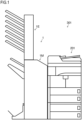
- Fig. 1 is a front view of an image forming system 301 according to one embodiment.
- the image forming system 301 includes an image forming apparatus 201 and a sheet post-processing apparatus 1.
- the image forming apparatus 201 is, for example, what is called a monochrome-printing multifunction peripheral that has an electrophotographic printing mechanism and that has functions such as printing, scanning (image reading), and facsimile transmission.
- the image forming apparatus 201 can be, for example, an apparatus such as a copier or printer, and can be a color-printing apparatus.
- the image forming apparatus 201 includes an image forming section, a transfer section, and a fixing section (none is shown).
- an electrostatic latent image of a document image formed on the surface of a photosensitive drum with laser light is supplied with toner to be developed to form a toner image of the document image.
- the transfer section transfers the toner image formed on the surface of the photosensitive drum to a sheet.
- the fixing section heats and presses the sheet having the toner image transferred to it to fix the toner image to the sheet. In this way, the image forming apparatus 201 forms (prints) an image on the sheet.
- the image forming apparatus 201 then conveys the sheet after image formation to the sheet post-processing apparatus 1.
- the sheet post-processing apparatus 1 is removably coupled to a side face of the image forming apparatus 201.
- the sheet post-processing apparatus 1 can be coupled in a similar manner to devices other than multifunction peripherals, such as copiers and printers.
- the sheet post-processing apparatus 1 performs predetermined post-processing on the sheet having undergone image formation (printing) in the image forming device 201.
- the sheet post-processing apparatus 1 includes a post-processing main unit 1M and an expansion unit 1E.
- the post-processing main unit 1M performs the predetermined post-processing on sheets and discharges the sheets to a first discharge tray 33, a second discharge tray (main-unit discharge tray) 53, or a third discharge tray 73, which will be described later.
- the expansion unit 1E is removably mounted on the post-processing main unit 1M, and sheets that have passed through the post-processing main unit 1M enter it.
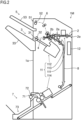
- Fig. 2 is a schematic sectional front view of the post-processing main unit 1M of the sheet post-processing apparatus 1 shown in Fig. 1 .
- the post-processing main unit 1M includes a sheet introduction passage 2, a first sheet discharge section 3, a first sheet discharge passage 4, a second sheet discharge section 5, a second sheet discharge passage 6, a third sheet discharge section 7, a third sheet discharge passage 8, a post-processing section 11, and a post-processing control section 12.
- the sheet introduction passage 2 has a sheet introduction port 2e.
- the sheet introduction port 2e is provided in the side face of the sheet post-processing apparatus 1 facing the image forming apparatus 201 and has an opening. Sheets conveyed from the image forming apparatus 201 to the sheet post-processing apparatus 1 are fed into the sheet post-processing apparatus 1 through the sheet introduction port 2e and the sheet introduction passage 2.
- the sheet introduction passage 2 extends in a generally horizonal direction, in a direction away from the image forming apparatus 201 (leftward in Fig. 2 ), from the sheet introducing port 2e to a sheet folding section 113, which will be described later.
- the sheet introduction passaged 2 has a first branch section 2a and a second branch section 2b, which are disposed in this order from upstream (from the sheet introducing passage 2e side) in the sheet conveyance direction.
- the first branch section 2a switches the sheet conveyance direction between a direction leading to the first and second sheet discharge sections 3 and 5 and a direction leading to the third sheet discharge section 7.
- the second branch section 2b switches the sheet conveyance direction between a direction leading to the first sheet discharge section 3 and a direction leading to the second sheet discharge section 5.
- the first sheet discharge section 3 is provided on the side face 1a of the sheet post-processing apparatus 1 opposite from its side facing the image forming apparatus 201.
- the first sheet discharge section 3 has a first discharge port 31, a pair of first discharge rollers 32, and a first discharge tray 33.
- the first discharge port 31 is located at the downstream end of the first sheet discharge passage 4 in the sheet discharge direction.
- the pair of first discharge rollers 32 is located at the first discharge port 31.
- the first discharge tray 33 is located downstream of the first discharge port 31 in the sheet discharge direction. A sheet conveyed through the first sheet discharge passage 4 and having reached the first discharge port 31 is discharged by the pair of the first discharge rollers 32 through the first discharge port 31 onto the first discharge tray 33.
- the first sheet discharge passage 4 is continuous from the downstream end of the sheet introduction passage 2 in the sheet discharge direction and extends in a generally horizontal direction, in a direction away from the image forming apparatus 201 (leftward in Fig. 2 ), to the first sheet discharge section 3.
- the second sheet discharge section 5 is provided on the side 1a of the sheet post-processing apparatus 1, above the first sheet discharge section 3.
- the second sheet discharge section 5 has a second discharge port 51, a pair of second discharge rollers 52, and a second discharge tray (main-unit discharge tray) 53.
- the second discharge port 51 is located at the downstream end of the second sheet discharge passage 6 in the sheet discharge direction.
- the pair of second discharge rollers 52 is located at the second discharge port 51.
- the second discharge tray 53 is located downstream of the second discharge port 51 in the sheet discharge direction. A sheet conveyed through the second sheet discharge passage 6 and having reached the second discharge port 51 is discharged by the pair of second discharge rollers 52 through the second discharge port 51 onto the second discharge tray 53.
- the second sheet discharge passage 6 branches from the second branch section 2b located in a downstream part of the sheet introduction passage 2 in the sheet discharge direction and extends laterally upward in a direction away from the image forming apparatus 201 (leftward in Fig. 2 ) up to the second sheet discharge section 5.
- the third sheet discharge section 7 is provided on the side face 1a of the sheet post-processing apparatus 1, below the first sheet discharge section 3. In other words, the third sheet discharge section 7 is disposed near a bottom part of the sheet post-processing apparatus 1.
- the third sheet discharge section 7 has a third discharge port 71, a pair of third discharge rollers 72, and a third discharge tray 73.
- the third discharge port 71 is located at the downstream end of the third sheet discharge passage 8 in the sheet discharge direction.
- the pair of third discharge rollers 72 is disposed at the third discharge port 71.
- the third discharge tray 73 is located downstream of the third discharge port 71 in the sheet discharge direction. A sheet conveyed through the third sheet discharge passage 8 and having reached the third discharge port 71 is discharged by the pair of third discharge rollers 72 through the third discharge port 71 onto the third discharge tray 73.
- the third sheet discharge passage 8 branches from the first branch section 2a located in a downstream part of the sheet introduction passage 2 in the sheet discharge direction and extends downward down to the third sheet discharge section 7.
- the post-processing section 11 performs predetermined processing on sheets that have undergone image formation by the image forming apparatus 201 and that have then been fed into the sheet post-processing apparatus 1.
- the post-processing section 11 includes a perforation section 111, a stapling section 112, a sheet folding section 113, and a bookbinding section 114.
- the perforation section 111 is disposed in the sheet introduction passage 2, closely downstream of the sheet introduction port 2e.
- the perforation section 111 can perform a perforation process on a sheet being conveyed on the sheet introduction passage 2 to form a punch hole in it.
- the stapling section 112 is disposed below the first sheet discharge passage 4, near the first sheet discharge section 3.
- the stapling section 112 can perform a stapling process (binding process) on a sheet bundle formed by stacking together multiple sheets to bind the sheet bundle.
- the sheet folding section 113 is disposed downstream of the perforation section 111, upstream of the stapling section 112, with respect to the sheet transport direction in the sheet introduction passage 2.
- the sheet folding section 113 can perform a folding process to a sheet to form a crease in it.
- the bookbinding section 114 is disposed in a downstream part of the third sheet discharge channel 8 in the sheet discharge direction, near the third sheet discharge section 7.
- the bookbinding section 114 can perform a middle-folding process and a middle-binding process to a sheet bundle formed by stacking together multiple sheets to fold and bind it generally at the middle and thereby form a booklet.
- the post-processing control section 12 includes a CPU, an image processing section, a memory section, and other electronic circuits and electronic components (none is shown).
- the post-processing control section 12 is communicatively connected to an image forming control section (not shown) in the image forming apparatus 201.
- the post-processing control section 12 receives instructions from the image forming control section and performs processing related to the functions of the sheet post-processing apparatus 1 by controlling the operation of the individual components in the sheet post-processing apparatus 1 using the CPU and based on control programs and data stored in the memory section.
- the sheet introduction passage 2, the first sheet discharge section 3, the first sheet discharge passage 4, the second sheet discharge section 5, the second sheet discharge passage 6, the third sheet discharge section 7, the third sheet discharge passage 8, and the post-processing section 11 individually receive instructions from the post-processing control section 12 and operate together to perform post-processing on sheets.
- the functions of the post-processing control unit 12 can be assumed by the image forming control section in the image forming apparatus 201.
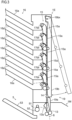
- Fig. 3 is a schematic sectional front view of the expansion unit 1E of the sheet post-processing apparatus 1 in Fig. 1 .
- Fig. 4 is an exterior perspective view of the expansion unit 1E in Fig. 3 .
- the expansion unit 1E is disposed above the post-processing main unit 1M.
- the post-processing main unit 1M includes a conveyance switching section 13.
- the expansion unit 1E includes a sheet conveyance passage 14, a sheet sorting section 15, a sheet discharge section 16, and a drive section 17.
- the conveyance switching section 13 is located in a top end part of the post-processing main unit 1M, above the second sheet discharge passage 6.
- the transport switching section 13 is located upstream of the second discharge port 51 in the sheet conveyance direction in the second sheet discharge passage 6.
- a switching guide 13a is disposed in the conveyance switching section 13, a switching guide 13a is disposed. With respect to the sheet conveyed along the second sheet discharge passage 6 downstream from the second branch section 2b, the switching guide 13a can be disposed either in a first position in which it conveys the sheet in a first direction f1 leading to the second sheet discharge section 5 or in a second position in which it conveys the sheet in a second direction f2 leading to the expansion unit 1E. In other words, with respect to the sheet passing through the post-processing main unit 1M, the switching guide 13a switches the sheet conveyance direction between the first direction f1 leading to the second discharge tray (main-unit discharge tray) 53 and the second direction f2 leading to the expansion unit 1E.
- the sheet conveyance passage 14 extends in the top-bottom direction in the expansion unit 1E.
- the sheet conveyance passage 14 connects to the conveyance switching section 13.
- the sheet conveyance passage 14 extends vertically from the conveyance switching section 13 up to a top end part of the expansion unit 1E.
- the sheet sorting section 15 is disposed on the sheet conveyance passage 14, downstream of the conveyance switching section 13 in the sheet conveyance direction.
- a plurality of sorting guides 15a are disposed.
- six swing guides 15a are disposed corresponding to the second-from-the-top to the bottommost sheet discharge trays 16a. If a sheet is not sorted by any of the sorting guides 15a up to the top end of the sheet conveyance passage 14, it is discharged to the topmost sheet discharge tray 16a.
- Each of the six swing guides 15a sorts the sheets conveyed along the sheet conveyance passage 14 downstream in the sheet conveyance direction from the conveyance switching section 13 to the sheet discharge tray 16a located to the side of the swing guide 15a.
- Fig. 3 shows how a sheet having entered the expansion unit 1E is sorted to the bottommost sheet discharge tray 16a.
- the sheet discharge section 16 is disposed downstream of the sheet sorting section 15 in the sheet conveyance direction.
- the sheet discharge section 16 is located above the side face 1a of the post-processing main unit 1M.
- the sheet discharge section 16 has sheet discharge trays 16a in multiple stages. In this embodiment, the sheet discharge section 16 has seven sheet discharge trays 16a.
- the sheet having passed through the post-processing main unit 1M and entered the expansion unit 1E is sorted by the sheet sorting section 15 on the sheet conveyance passage 14 and is discharged to one of the seven sheet discharge trays 16a.
- the sheet discharge trays 16a are one of final discharge locations for sheets that have been post-processed by the sheet post-processing apparatus 1.
- the drive unit 17 is disposed in an end part in the sheet width direction (paper depth direction in Fig. 3 ), which is orthogonal to the sheet conveyance direction in the sheet conveyance passage 14.
- the drive section 17 has pulleys 17a, a belt 17b, a pressing piece 17c, a plurality of sorting swing pieces 17d, a switching swing piece 17e, and a guide contact member 17f.
- the pulleys 17a are disposed at two locations, at the top and at the bottom of the expansion unit 1E. Each of the two pulleys 17a is supported on a shaft 17ax extending in the sheet width direction and can rotate about the axis of the shaft 17ax. One of the two pulleys 17a is connected to a motor (not shown) and is rotated by the motor. The operation of the motor is controlled by the post-processing control unit 12 or the image forming control unit in the image forming apparatus 201.
- the belt 17b is formed in a ring shape and is wound around the two pulleys 17a. In other words, the belt 17b describes an oval extending in the top-bottom direction. The belt 17b is rotated along the circumferences of the two pulleys 17a by the motor connected to the pulleys 17a.
- the pressing piece 17c is fixed to the outer circumference of the belt 17b and protrudes outward of the belt 17b.
- the pressing piece 17c moves along the track of the belt 17b as the belt 17b rotates. As it moves, the pressing piece 17c makes contact with and displaces each of the sorting swing piece 17d and the switching swing piece 17e
- the plurality of sorting swinging pieces 17d are each disposed on the track of the pressing piece 17c, which moves with the rotation of the belt 17b.
- the plurality of sorting swing pieces 17d six of them are disposed corresponding to the number of sorting guides 15a. That is, six pairs of a sorting swing piece 17d and a sorting guide 15a are disposed.
- the six sorting swing pieces 17d, corresponding to the six sorting guides 15a, are disposed one above another in the top-bottom direction along the sheet conveyance passage 14.
- Each pair of a sorting swing piece 17d and a sorting guide 15a is supported on a shaft 17dx extending in the sheet width direction and is swingable (rotatable) about the axis of the shaft 17dx.
- the sorting swing piece 17d is urged by a spring (not shown) or by the action of gravity so that the sorting guide 15a is disposed in such a position that the sheet is conveyed vertically upward along the sheet conveyance passage 14.
- the pressing piece 17c which moves together with the belt 17b, makes contact with the sorting swing piece 17d, and the sorting swing piece 17d is displaced against the urging force so that the sorting guide 15a is disposed in such a position as to sort the sheet to the sheet discharge tray 16a.
- the switching swing piece 17e is disposed below the lower pulley 17a.
- the switching swing piece 17e is disposed on the track of the pressing piece 17c, which moves with the rotation of the belt 17b.
- the switching swing piece 17e is supported on a shaft 17ex extending in the sheet width direction and is rotatable about the axis of the shaft 17ex.
- the switching swing piece 17e has, radially outward of the shaft 17ex, a coupling portion 17ec to which the guide contact member 17f is rotatably coupled.
- the switching swing piece 17e is urged by a spring (not shown) so that the guide contact member 17f coupled to the coupling portion 17ec is disposed in an upper position.
- the expansion unit 1E is mounted on the post-processing main unit 1M and a sheet passing inside the post-processing main unit 1M is discharged to the second sheet discharge section 5, the pressing piece 17c, which moves together with the belt 17b, makes contact with the switching swing piece 17e, and the switching swing piece 17e is displaced against the urging force so that the guide contact member 17f is disposed in a lower position.
- the guide contact member 17f is disposed below the switching swing piece 17e, in a bottom end part of the expansion unit 1E.
- the guide contact member 17f is formed as a rod extending generally in the top-bottom direction and is coupled at a top end part of it to the coupling portion 17ec of the switching swing piece 17e.
- the guide contact member 17f is disposed either in an upper position or in a lower position, which is below the upper position, as the switching swing piece 17e swings about the axis of the shaft 17ex.
- a bottom part of the guide contact member 17f protrudes through a hole 1Eh in the bottom plate 1Eb of the expansion unit 1E to below the bottom plate 1Eb.
- a bottom end part of the guide contact member 17f makes contact with the switching guide 13a when the expansion unit 1E is mounted on the post-processing main unit 1M.
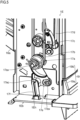
- Figs. 5 and 6 are, respectively, a perspective part view around the guide contact member 17f in the expansion unit 1E in Fig. 4 and a sectional front view around the switching guide 13a in the sheet post-processing apparatus 1 in Fig. 3 as observed when a sheet is discharged from the expansion unit 1E.
- Fig. 7 is a perspective part view around the switching guide 13a in Fig. 6 .
- Figs. 8 and 9 are, respectively, a partial perspective view around the guide contact member 17f in the expansion unit 1E in Fig. 4 and a sectional front view around the switching guide 13a in the sheet post-processing apparatus 1 in Fig. 3 as observed when a sheet is discharged from the post-processing main unit 1M.
- Fig. 10 is a perspective part view around the switching guide 13a in Fig. 9 .
- Figs. 5 , 6 , and 7 show a state where the expansion unit 1E is mounted on the post-processing main unit 1M and where sheets passing through the post-processing main unit 1M are directed to the expansion unit 1E. Note that Fig. 5 shows no part of the post-processing main unit 1M and Figs. 6 and 7 do not show some components of the post-processing main unit 1M are not shown.
- the pressing piece 17c fixed to the belt 17b is separated from the switching swing piece 17e.
- the pressing piece 17c makes contact with the bottommost sorting swing piece 17d and displaces the swinging piece 17d so that the swinging guide 15a is disposed in such a position as to sort the sheet to the bottommost sheet discharge tray 16a (here, Figs. 3 and 4 ).
- the switching swing piece 17e rotates clockwise in Fig. 5 under the urging force of a spring (not shown) to pull up the guide contact member 17f. In this way, the contact member 17f is disposed in the upper position.
- the bottom end part of the guide contact member 17f makes contact with the switching guide 13a in the conveyance switching section 13.
- the switching guide 13a is urged with a spring (not shown) or by the action of gravity so as to be disposed in the second position in which it directs the sheets passing through the post-processing main unit 1M to the expansion unit 1E.
- the guide contact member 17f With the guide contact member 17f disposed in the upper position, the guide contact member 17f exerts no force that pushes the switching guide 13a downward.
- the switching guide 13a is disposed in the second position in which it conveys the sheets passing through the post-processing main unit 1M in the second direction f2 leading to the expansion unit 1E.
- Figs. 8 , 9 , and 10 show a state where the expansion unit 1E is mounted on the post-processing main unit 1M and where sheets passing through the post-processing main unit 1M are directed to the second sheet discharge section (main-unit discharge tray) 5. Note that Fig. 8 shows no part of the post-processing main unit 1M and Figs. 9 and 10 do not show some components of the post-processing main unit 1M.
- the pressing piece 17c fixed to the belt 17b makes contact with the switching swing piece 17e.
- the switching piece 17e rotates counter-clockwise in Fig. 5 to push the guide contact member 17f downward.
- the guide contact member 17f is disposed in the lower position.
- the guide contact member 17f With the guide contact member 17f disposed in the lower position, the guide contact member 17f exerts a force that pushes the switching guide 13a downward.
- the switching guide 13a is disposed in the first position against the urging force from the spring or by the action of gravity to convey the sheet passing through the post-processing main unit 1M in the first direction f1 leading to the second sheet discharge tray 53.
- the sheet post-processing apparatus 1 includes, in the post-processing main unit 1M, a switching guide 13a that directs sheets from the post-processing main unit 1M to the expansion unit 1E.
- a switching guide 13a that directs sheets from the post-processing main unit 1M to the expansion unit 1E. This eliminates the need to provide a switching guide 13 for each of various types of expansion units 1E that can be mounted on the post-processing main unit 1M and helps reduce the cost of the expansion unit 1E.
- the low-cost configuration helps enhance the functionality of the sheet post-processing apparatus 1.
- the post-processing main unit 1M includes a cover member 18 as shown in Figs. 11 and 12 .
- Fig. 11 is a sectional front view around the switching guide 13a in the sheet post-processing apparatus 1 with the cover member 18 fitted on it.
- Fig. 12 is a perspective part view around the switching guide 13a in Fig. 11 .
- the cover member 18 is disposed in a top end part of the post-processing main unit 1M.
- the cover member 18 is formed in the shape of a flat plate extending in a horizonal direction and covers the top end part of the post-processing main unit 1M.
- the cover member 18 is removably fitted to the top end part of the post-processing main unit 1M in place of the expansion unit 1E when this is not mounted.
- the cover member 18 has a guide regulation portion 18a.
- the guide regulation portion 18a is disposed on the bottom surface of the cover member 18 and is formed as a projection protruding downward.
- the guide regulation portion 18a is disposed at the same position where the guide contact member 17f is disposed when the expansion unit 1E is mounted on the post-processing main unit 1M.
- the guide regulation portion 18a is disposed at the same position ( Figs, 8 , 10 ) where the guide contact member 17f is disposed when pushed below by the pressing piece 17c and disposed in the lower position.
- the guide regulation portion 18a makes contact with the switching guide 13a when the cover member 18 is fitted to the post-processing main unit 1M.
- the switching guide 13a is disposed in the first position against the urging force from the spring or by the action of gravity to convey the sheet passing through the post-processing main unit 1M in the first direction f1 leading to the second discharge tray 53.
- the guide regulation portion 18a changes the position of the switching guide 13a to the first direction in which it guides the sheet to the second discharge tray 53.
- disposing the cover member 18 covering the top end part of the post-processing main unit 1M on the post-processing main unit 1M allows the switching guide 13a to be automatically disposed in the first position in which it conveys the sheets in the first direction f1 leading to the second discharge tray 53. This eliminates the need to provide a component that drives the switching guide 13a and helps reduce the cost of post-processing main unit 1M.
- the low-cost configuration helps enhance the functionality of the sheet post-processing apparatus 1.
- the expansion unit 1E includes a conveyance guide 19.
- the conveyance guide 19 is disposed on the side face of the expansion unit 1E facing the image forming apparatus 201, opposite from the side face on which the sheet discharge section 16 is disposed.
- the conveyance guide 19 is an exterior member covering the side face of the expansion unit 1E and is formed in the shape of a flat plate extending in the top-bottom and front-back directions.
- the conveyance guide 19 on its inner surface guides a sheet being conveyed in the sheet conveyance passage 14.
- part of a bottom portion of the conveyance guide 19 is inserted into the post-processing main unit 1M when the expansion unit 1E is mounted on the post-processing main unit 1M.
- the conveyance guide 19 faces the switching guide 13a across the conveyance passage of the sheet conveyed in the second direction f2.
- the conveyance guide 19 has a fixed guide portion 19a and a movable guide portion 19b.
- the fixed guide section 19a and the movable guide section 19b are continuously disposed one above the other in the top-bottom direction.
- the fixed guide section 19a is disposed in a bottom part of the expansion unit 1E and is located below the movable guide section 19b.
- the fixed guide portion 19a is inserted into the post-processing main unit 1M when the expansion unit 1E is mounted on the post-processing main unit 1M.
- the fixed guide portion 19a extends out of the post-processing main unit 1M into the expansion unit 1E.
- the movable guide section 19b is disposed in a top part of the expansion unit 1E and is located above the fixed guide section 19a. As shown in Fig. 3 , the movable guide portion 19b is supported on a shaft 19bx disposed in an upper end part and extending in the sheet width direction and is rotatable about the axis of the shaft 19bx. The movable guide portion 19b is openable and closable by rotating about the axis of the shaft 19bx so as to expose the sheet conveyance passage 14 in the expansion unit 1E.
- the sheet conveyance passage 14 can be exposed, allowing easy access to the sheet conveyance passage 14 and the sheet sorting section 15. This makes it easy to maintain the sheet conveyance passage in the expansion unit 1E and to troubleshoot problems.
- the expansion unit 1E has sheet discharge trays 16a in multiple stages to which the sheets entering from the post-processing main unit 1M are sorted and discharged. As described above, in this embodiment, the expansion unit 1E has seven sheet discharge trays 16a. That is, the expansion unit 1E of this embodiment is a unit equipped with a function called a mailbox having sheet discharge trays in multiple stages disposed one above another in the top-bottom direction. Thus, according to this embodiment, it is possible to reduce the number of components in the expansion unit 1E having the function of a mailbox and thereby to reduce costs.
- expansion unit 1E is a unit equipped with the function of a mailbox having sheet ejection trays in multiple stages, this is not meant as any limitation to such an apparatus.
- the expansion unit may be a unit having any function other than that of a mailbox.
Landscapes
- Physics & Mathematics (AREA)
- General Physics & Mathematics (AREA)
- Engineering & Computer Science (AREA)
- Mechanical Engineering (AREA)
- Separation, Sorting, Adjustment, Or Bending Of Sheets To Be Conveyed (AREA)
- Paper Feeding For Electrophotography (AREA)
- Electrophotography Configuration And Component (AREA)
- Folding Of Thin Sheet-Like Materials, Special Discharging Devices, And Others (AREA)
Abstract
Description
- The present disclosure relates to a sheet post-processing apparatus that performs post-processing on a sheet having an image formed on it by the image forming apparatus, and relates also to an image forming system provided with such a sheet post-processing apparatus.
- There are known sheet post-processing apparatuses that perform post-processing, such as binding and folding, on sheets having images formed on them by an image forming apparatus such as a copier or printer. Such sheet post processing apparatuses are often configured so that a variety of expansion units with different functions are removably mountable on them.
- An object of the present disclosure is to provide a sheet post-processing apparatus and an image forming system that a low-cost configuration help enhance the functionality.
- According to one aspect of the present disclosure, a sheet post-processing apparatus includes a post-processing main unit and an expansion unit. The post-processing main unit performs predetermined post-processing on a sheet and discharges the sheet to a main-unit discharge tray. The expansion unit, into which the sheet having passed through the post-processing main unit is introduced, is removably mounted on the post-processing main unit. The post-processing main unit includes a switching guide that switches the conveyance direction of the sheet passing through the post-processing main unit between a first direction leading to the main unit discharged tray and a second direction leading to the expansion unit. The expansion unit includes a guide contact member that, when the expansion unit is mounted on the post-processing main unit, makes contact with the switching guide to switch the switching guide to a position for the second direction.
-
-
Fig. 1 is a front view of an image forming system according to one embodiment of the present disclosure. -
Fig. 2 is a schematic sectional front view of a post-processing main unit of a sheet post-processing apparatus inFig. 1 . -
Fig. 3 is a schematic sectional front view of an expansion unit of the sheet post-processing apparatus inFig. 1 . -
Fig. 4 is an exterior perspective view of the expansion unit inFig. 3 . -
Fig. 5 is a perspective part view around a guide contact member in the expansion unit inFig. 4 as observed when a sheet is discharged from the expansion unit. -
Fig. 6 is a sectional front view around a switching guide in the sheet post-processing apparatus inFig. 3 as observed when a sheet is discharged from the expansion unit. -
Fig. 7 is a perspective part view around the switching guide inFig. 6 . -
Fig. 8 is a perspective part view around the guide contact member in the expansion unit inFig. 4 as observed when a sheet is discharged from the post-processing main unit. -
Fig. 9 is a sectional front view around the switching guide in the sheet post-processing apparatus inFig. 3 as observed when a sheet is discharged from the post-processing main unit. -
Fig. 10 is a perspective part view around the switching guide inFig. 9 . -
Fig. 11 is a sectional front view around the switching guide in the sheet post-processing apparatus with a cover member fitted on it. -
Fig. 12 is a perspective part view around the switching guide inFig. 11 . - An embodiment of the present disclosure will be described below with reference to the accompanying drawings. The scope of the present disclosure is not limited to what is described herein.
-
Fig. 1 is a front view of animage forming system 301 according to one embodiment. As shown inFig. 1 , theimage forming system 301 includes animage forming apparatus 201 and asheet post-processing apparatus 1. - The
image forming apparatus 201 is, for example, what is called a monochrome-printing multifunction peripheral that has an electrophotographic printing mechanism and that has functions such as printing, scanning (image reading), and facsimile transmission. Theimage forming apparatus 201 can be, for example, an apparatus such as a copier or printer, and can be a color-printing apparatus. - The
image forming apparatus 201 includes an image forming section, a transfer section, and a fixing section (none is shown). In the image forming section, an electrostatic latent image of a document image formed on the surface of a photosensitive drum with laser light is supplied with toner to be developed to form a toner image of the document image. The transfer section transfers the toner image formed on the surface of the photosensitive drum to a sheet. The fixing section heats and presses the sheet having the toner image transferred to it to fix the toner image to the sheet. In this way, theimage forming apparatus 201 forms (prints) an image on the sheet. Theimage forming apparatus 201 then conveys the sheet after image formation to thesheet post-processing apparatus 1. - The
sheet post-processing apparatus 1 is removably coupled to a side face of theimage forming apparatus 201. Thesheet post-processing apparatus 1 can be coupled in a similar manner to devices other than multifunction peripherals, such as copiers and printers. Thesheet post-processing apparatus 1 performs predetermined post-processing on the sheet having undergone image formation (printing) in theimage forming device 201. - As shown in
Fig. 1 , thesheet post-processing apparatus 1 includes a post-processingmain unit 1M and anexpansion unit 1E. The post-processingmain unit 1M performs the predetermined post-processing on sheets and discharges the sheets to afirst discharge tray 33, a second discharge tray (main-unit discharge tray) 53, or athird discharge tray 73, which will be described later. Theexpansion unit 1E is removably mounted on the post-processingmain unit 1M, and sheets that have passed through the post-processingmain unit 1M enter it. -
Fig. 2 is a schematic sectional front view of the post-processingmain unit 1M of thesheet post-processing apparatus 1 shown inFig. 1 . As shown inFig. 2 , the post-processingmain unit 1M includes asheet introduction passage 2, a firstsheet discharge section 3, a firstsheet discharge passage 4, a second sheet discharge section 5, a secondsheet discharge passage 6, a thirdsheet discharge section 7, a thirdsheet discharge passage 8, apost-processing section 11, and apost-processing control section 12. - The
sheet introduction passage 2 has asheet introduction port 2e. Thesheet introduction port 2e is provided in the side face of thesheet post-processing apparatus 1 facing theimage forming apparatus 201 and has an opening. Sheets conveyed from theimage forming apparatus 201 to thesheet post-processing apparatus 1 are fed into thesheet post-processing apparatus 1 through thesheet introduction port 2e and thesheet introduction passage 2. - The
sheet introduction passage 2 extends in a generally horizonal direction, in a direction away from the image forming apparatus 201 (leftward inFig. 2 ), from thesheet introducing port 2e to asheet folding section 113, which will be described later. Thesheet introduction passaged 2 has afirst branch section 2a and asecond branch section 2b, which are disposed in this order from upstream (from thesheet introducing passage 2e side) in the sheet conveyance direction. - With respect to the sheet conveyed downstream from the
sheet introduction port 2e, thefirst branch section 2a switches the sheet conveyance direction between a direction leading to the first and secondsheet discharge sections 3 and 5 and a direction leading to the thirdsheet discharge section 7. With respect to the sheet conveyed downstream from thesheet introduction port 2e, thesecond branch section 2b switches the sheet conveyance direction between a direction leading to the firstsheet discharge section 3 and a direction leading to the second sheet discharge section 5. - The first
sheet discharge section 3 is provided on theside face 1a of thesheet post-processing apparatus 1 opposite from its side facing theimage forming apparatus 201. The firstsheet discharge section 3 has afirst discharge port 31, a pair offirst discharge rollers 32, and afirst discharge tray 33. - The
first discharge port 31 is located at the downstream end of the firstsheet discharge passage 4 in the sheet discharge direction. The pair offirst discharge rollers 32 is located at thefirst discharge port 31. Thefirst discharge tray 33 is located downstream of thefirst discharge port 31 in the sheet discharge direction. A sheet conveyed through the firstsheet discharge passage 4 and having reached thefirst discharge port 31 is discharged by the pair of thefirst discharge rollers 32 through thefirst discharge port 31 onto thefirst discharge tray 33. - The first
sheet discharge passage 4 is continuous from the downstream end of thesheet introduction passage 2 in the sheet discharge direction and extends in a generally horizontal direction, in a direction away from the image forming apparatus 201 (leftward inFig. 2 ), to the firstsheet discharge section 3. - The second sheet discharge section 5 is provided on the
side 1a of thesheet post-processing apparatus 1, above the firstsheet discharge section 3. The second sheet discharge section 5 has asecond discharge port 51, a pair ofsecond discharge rollers 52, and a second discharge tray (main-unit discharge tray) 53. - The
second discharge port 51 is located at the downstream end of the secondsheet discharge passage 6 in the sheet discharge direction. The pair ofsecond discharge rollers 52 is located at thesecond discharge port 51. Thesecond discharge tray 53 is located downstream of thesecond discharge port 51 in the sheet discharge direction. A sheet conveyed through the secondsheet discharge passage 6 and having reached thesecond discharge port 51 is discharged by the pair ofsecond discharge rollers 52 through thesecond discharge port 51 onto thesecond discharge tray 53. - The second
sheet discharge passage 6 branches from thesecond branch section 2b located in a downstream part of thesheet introduction passage 2 in the sheet discharge direction and extends laterally upward in a direction away from the image forming apparatus 201 (leftward inFig. 2 ) up to the second sheet discharge section 5. - The third
sheet discharge section 7 is provided on theside face 1a of the sheetpost-processing apparatus 1, below the firstsheet discharge section 3. In other words, the thirdsheet discharge section 7 is disposed near a bottom part of the sheetpost-processing apparatus 1. The thirdsheet discharge section 7 has athird discharge port 71, a pair ofthird discharge rollers 72, and athird discharge tray 73. - The
third discharge port 71 is located at the downstream end of the thirdsheet discharge passage 8 in the sheet discharge direction. The pair ofthird discharge rollers 72 is disposed at thethird discharge port 71. Thethird discharge tray 73 is located downstream of thethird discharge port 71 in the sheet discharge direction. A sheet conveyed through the thirdsheet discharge passage 8 and having reached thethird discharge port 71 is discharged by the pair ofthird discharge rollers 72 through thethird discharge port 71 onto thethird discharge tray 73. - The third
sheet discharge passage 8 branches from thefirst branch section 2a located in a downstream part of thesheet introduction passage 2 in the sheet discharge direction and extends downward down to the thirdsheet discharge section 7. - The
post-processing section 11 performs predetermined processing on sheets that have undergone image formation by theimage forming apparatus 201 and that have then been fed into the sheetpost-processing apparatus 1. Thepost-processing section 11 includes aperforation section 111, astapling section 112, asheet folding section 113, and abookbinding section 114. - The
perforation section 111 is disposed in thesheet introduction passage 2, closely downstream of thesheet introduction port 2e. Theperforation section 111 can perform a perforation process on a sheet being conveyed on thesheet introduction passage 2 to form a punch hole in it. - The
stapling section 112 is disposed below the firstsheet discharge passage 4, near the firstsheet discharge section 3. Thestapling section 112 can perform a stapling process (binding process) on a sheet bundle formed by stacking together multiple sheets to bind the sheet bundle. - The
sheet folding section 113 is disposed downstream of theperforation section 111, upstream of thestapling section 112, with respect to the sheet transport direction in thesheet introduction passage 2. Thesheet folding section 113 can perform a folding process to a sheet to form a crease in it. - The
bookbinding section 114 is disposed in a downstream part of the thirdsheet discharge channel 8 in the sheet discharge direction, near the thirdsheet discharge section 7. Thebookbinding section 114 can perform a middle-folding process and a middle-binding process to a sheet bundle formed by stacking together multiple sheets to fold and bind it generally at the middle and thereby form a booklet. - The
post-processing control section 12 includes a CPU, an image processing section, a memory section, and other electronic circuits and electronic components (none is shown). Thepost-processing control section 12 is communicatively connected to an image forming control section (not shown) in theimage forming apparatus 201. Thepost-processing control section 12 receives instructions from the image forming control section and performs processing related to the functions of the sheetpost-processing apparatus 1 by controlling the operation of the individual components in the sheetpost-processing apparatus 1 using the CPU and based on control programs and data stored in the memory section. Thesheet introduction passage 2, the firstsheet discharge section 3, the firstsheet discharge passage 4, the second sheet discharge section 5, the secondsheet discharge passage 6, the thirdsheet discharge section 7, the thirdsheet discharge passage 8, and thepost-processing section 11 individually receive instructions from thepost-processing control section 12 and operate together to perform post-processing on sheets. The functions of thepost-processing control unit 12 can be assumed by the image forming control section in theimage forming apparatus 201. -
Fig. 3 is a schematic sectional front view of theexpansion unit 1E of the sheetpost-processing apparatus 1 inFig. 1 .Fig. 4 is an exterior perspective view of theexpansion unit 1E inFig. 3 . As shown inFig. 1 , theexpansion unit 1E is disposed above the post-processingmain unit 1M. As shown inFig. 3 , the post-processingmain unit 1M includes aconveyance switching section 13. As shown inFigs. 3 and4 , theexpansion unit 1E includes asheet conveyance passage 14, asheet sorting section 15, asheet discharge section 16, and adrive section 17. - The
conveyance switching section 13 is located in a top end part of the post-processingmain unit 1M, above the secondsheet discharge passage 6. Thetransport switching section 13 is located upstream of thesecond discharge port 51 in the sheet conveyance direction in the secondsheet discharge passage 6. - In the
conveyance switching section 13, a switchingguide 13a is disposed. With respect to the sheet conveyed along the secondsheet discharge passage 6 downstream from thesecond branch section 2b, the switchingguide 13a can be disposed either in a first position in which it conveys the sheet in a first direction f1 leading to the second sheet discharge section 5 or in a second position in which it conveys the sheet in a second direction f2 leading to theexpansion unit 1E. In other words, with respect to the sheet passing through the post-processingmain unit 1M, the switchingguide 13a switches the sheet conveyance direction between the first direction f1 leading to the second discharge tray (main-unit discharge tray) 53 and the second direction f2 leading to theexpansion unit 1E. - The
sheet conveyance passage 14 extends in the top-bottom direction in theexpansion unit 1E. When theexpansion unit 1E is mounted on the post-processingmain unit 1M, thesheet conveyance passage 14 connects to theconveyance switching section 13. Thesheet conveyance passage 14 extends vertically from theconveyance switching section 13 up to a top end part of theexpansion unit 1E. - The
sheet sorting section 15 is disposed on thesheet conveyance passage 14, downstream of theconveyance switching section 13 in the sheet conveyance direction. In thesheet sorting section 15, a plurality of sortingguides 15a are disposed. There are disposed as many sorting guides 15a as the number ofsheet discharge trays 16a, which will be described later, provided in thesheet discharge section 16. In this embodiment, sixswing guides 15a are disposed corresponding to the second-from-the-top to the bottommostsheet discharge trays 16a. If a sheet is not sorted by any of the sorting guides 15a up to the top end of thesheet conveyance passage 14, it is discharged to the topmostsheet discharge tray 16a. - Each of the six swing guides 15a sorts the sheets conveyed along the
sheet conveyance passage 14 downstream in the sheet conveyance direction from theconveyance switching section 13 to thesheet discharge tray 16a located to the side of theswing guide 15a.Fig. 3 shows how a sheet having entered theexpansion unit 1E is sorted to the bottommostsheet discharge tray 16a. - The
sheet discharge section 16 is disposed downstream of thesheet sorting section 15 in the sheet conveyance direction. Thesheet discharge section 16 is located above theside face 1a of the post-processingmain unit 1M. Thesheet discharge section 16 hassheet discharge trays 16a in multiple stages. In this embodiment, thesheet discharge section 16 has sevensheet discharge trays 16a. - The sheet having passed through the post-processing
main unit 1M and entered theexpansion unit 1E is sorted by thesheet sorting section 15 on thesheet conveyance passage 14 and is discharged to one of the sevensheet discharge trays 16a. Thesheet discharge trays 16a are one of final discharge locations for sheets that have been post-processed by the sheetpost-processing apparatus 1. - The
drive unit 17 is disposed in an end part in the sheet width direction (paper depth direction inFig. 3 ), which is orthogonal to the sheet conveyance direction in thesheet conveyance passage 14. Thedrive section 17 haspulleys 17a, abelt 17b, apressing piece 17c, a plurality of sortingswing pieces 17d, aswitching swing piece 17e, and aguide contact member 17f. - The
pulleys 17a are disposed at two locations, at the top and at the bottom of theexpansion unit 1E. Each of the twopulleys 17a is supported on a shaft 17ax extending in the sheet width direction and can rotate about the axis of the shaft 17ax. One of the twopulleys 17a is connected to a motor (not shown) and is rotated by the motor. The operation of the motor is controlled by thepost-processing control unit 12 or the image forming control unit in theimage forming apparatus 201. - The
belt 17b is formed in a ring shape and is wound around the twopulleys 17a. In other words, thebelt 17b describes an oval extending in the top-bottom direction. Thebelt 17b is rotated along the circumferences of the twopulleys 17a by the motor connected to thepulleys 17a. - The
pressing piece 17c is fixed to the outer circumference of thebelt 17b and protrudes outward of thebelt 17b. Thepressing piece 17c moves along the track of thebelt 17b as thebelt 17b rotates. As it moves, thepressing piece 17c makes contact with and displaces each of thesorting swing piece 17d and theswitching swing piece 17e - The plurality of sorting swinging
pieces 17d are each disposed on the track of thepressing piece 17c, which moves with the rotation of thebelt 17b. In this embodiment, as the plurality of sortingswing pieces 17d, six of them are disposed corresponding to the number of sorting guides 15a. That is, six pairs of asorting swing piece 17d and a sortingguide 15a are disposed. The sixsorting swing pieces 17d, corresponding to the six sortingguides 15a, are disposed one above another in the top-bottom direction along thesheet conveyance passage 14. Each pair of asorting swing piece 17d and a sortingguide 15a is supported on a shaft 17dx extending in the sheet width direction and is swingable (rotatable) about the axis of the shaft 17dx. - The sorting
swing piece 17d is urged by a spring (not shown) or by the action of gravity so that the sortingguide 15a is disposed in such a position that the sheet is conveyed vertically upward along thesheet conveyance passage 14. When the sheet is sorted to the correspondingsheet discharge tray 16a, thepressing piece 17c, which moves together with thebelt 17b, makes contact with the sortingswing piece 17d, and thesorting swing piece 17d is displaced against the urging force so that the sortingguide 15a is disposed in such a position as to sort the sheet to thesheet discharge tray 16a. - The switching
swing piece 17e is disposed below thelower pulley 17a. The switchingswing piece 17e is disposed on the track of thepressing piece 17c, which moves with the rotation of thebelt 17b. The switchingswing piece 17e is supported on a shaft 17ex extending in the sheet width direction and is rotatable about the axis of the shaft 17ex. The switchingswing piece 17e has, radially outward of the shaft 17ex, a coupling portion 17ec to which theguide contact member 17f is rotatably coupled. - The switching
swing piece 17e is urged by a spring (not shown) so that theguide contact member 17f coupled to the coupling portion 17ec is disposed in an upper position. When theexpansion unit 1E is mounted on the post-processingmain unit 1M and a sheet passing inside the post-processingmain unit 1M is discharged to the second sheet discharge section 5, thepressing piece 17c, which moves together with thebelt 17b, makes contact with the switchingswing piece 17e, and theswitching swing piece 17e is displaced against the urging force so that theguide contact member 17f is disposed in a lower position. - The
guide contact member 17f is disposed below the switchingswing piece 17e, in a bottom end part of theexpansion unit 1E. Theguide contact member 17f is formed as a rod extending generally in the top-bottom direction and is coupled at a top end part of it to the coupling portion 17ec of theswitching swing piece 17e. Theguide contact member 17f is disposed either in an upper position or in a lower position, which is below the upper position, as theswitching swing piece 17e swings about the axis of the shaft 17ex. - A bottom part of the
guide contact member 17f protrudes through a hole 1Eh in the bottom plate 1Eb of theexpansion unit 1E to below the bottom plate 1Eb. A bottom end part of theguide contact member 17f makes contact with the switchingguide 13a when theexpansion unit 1E is mounted on the post-processingmain unit 1M. - Next, the movement of the switching
guide 13a will be described with reference toFigs. 5 to 10 .Figs. 5 and6 are, respectively, a perspective part view around theguide contact member 17f in theexpansion unit 1E inFig. 4 and a sectional front view around the switchingguide 13a in the sheetpost-processing apparatus 1 inFig. 3 as observed when a sheet is discharged from theexpansion unit 1E.Fig. 7 is a perspective part view around the switchingguide 13a inFig. 6 .Figs. 8 and9 are, respectively, a partial perspective view around theguide contact member 17f in theexpansion unit 1E inFig. 4 and a sectional front view around the switchingguide 13a in the sheetpost-processing apparatus 1 inFig. 3 as observed when a sheet is discharged from the post-processingmain unit 1M.Fig. 10 is a perspective part view around the switchingguide 13a inFig. 9 . -
Figs. 5 ,6 , and7 show a state where theexpansion unit 1E is mounted on the post-processingmain unit 1M and where sheets passing through the post-processingmain unit 1M are directed to theexpansion unit 1E. Note thatFig. 5 shows no part of the post-processingmain unit 1M andFigs. 6 and7 do not show some components of the post-processingmain unit 1M are not shown. - When a sheet passing through the post-processing
main unit 1M is directed to theexpansion unit 1E, as shown inFig. 5 and7 , thepressing piece 17c fixed to thebelt 17b is separated from the switchingswing piece 17e. For example, as shown inFig. 5 , thepressing piece 17c makes contact with the bottommostsorting swing piece 17d and displaces the swingingpiece 17d so that the swingingguide 15a is disposed in such a position as to sort the sheet to the bottommostsheet discharge tray 16a (here,Figs. 3 and4 ). - With the
pressing piece 17c separated from the switchingswing piece 17e, the switchingswing piece 17e rotates clockwise inFig. 5 under the urging force of a spring (not shown) to pull up theguide contact member 17f. In this way, thecontact member 17f is disposed in the upper position. - With the
expansion unit 1E mounted on the post-processingmain unit 1M, the bottom end part of theguide contact member 17f makes contact with the switchingguide 13a in theconveyance switching section 13. Here, the switchingguide 13a is urged with a spring (not shown) or by the action of gravity so as to be disposed in the second position in which it directs the sheets passing through the post-processingmain unit 1M to theexpansion unit 1E. - With the
guide contact member 17f disposed in the upper position, theguide contact member 17f exerts no force that pushes the switchingguide 13a downward. Thus, as shown inFigs. 6 and7 , urged with the spring or by the action of gravity, the switchingguide 13a is disposed in the second position in which it conveys the sheets passing through the post-processingmain unit 1M in the second direction f2 leading to theexpansion unit 1E. -
Figs. 8 ,9 , and10 show a state where theexpansion unit 1E is mounted on the post-processingmain unit 1M and where sheets passing through the post-processingmain unit 1M are directed to the second sheet discharge section (main-unit discharge tray) 5. Note thatFig. 8 shows no part of the post-processingmain unit 1M andFigs. 9 and10 do not show some components of the post-processingmain unit 1M. - When a sheet passing through the post-processing
main unit 1M is directed to the second sheet discharge section 5, as shown inFigs. 8 and10 , thepressing piece 17c fixed to thebelt 17b makes contact with the switchingswing piece 17e. With thepressing piece 17c in contact with the switchingswing piece 17e, under a force received from the contactingpressing piece 17c with which it is in contact, theswitching piece 17e rotates counter-clockwise inFig. 5 to push theguide contact member 17f downward. Thus, theguide contact member 17f is disposed in the lower position. - With the
guide contact member 17f disposed in the lower position, theguide contact member 17f exerts a force that pushes the switchingguide 13a downward. Thus, as shown inFigs. 9 and10 , the switchingguide 13a is disposed in the first position against the urging force from the spring or by the action of gravity to convey the sheet passing through the post-processingmain unit 1M in the first direction f1 leading to the secondsheet discharge tray 53. - With the above configuration, the sheet
post-processing apparatus 1 includes, in the post-processingmain unit 1M, a switchingguide 13a that directs sheets from the post-processingmain unit 1M to theexpansion unit 1E. This eliminates the need to provide a switchingguide 13 for each of various types ofexpansion units 1E that can be mounted on the post-processingmain unit 1M and helps reduce the cost of theexpansion unit 1E. The low-cost configuration helps enhance the functionality of the sheetpost-processing apparatus 1. - Also, the post-processing
main unit 1M includes acover member 18 as shown inFigs. 11 and12 .Fig. 11 is a sectional front view around the switchingguide 13a in the sheetpost-processing apparatus 1 with thecover member 18 fitted on it.Fig. 12 is a perspective part view around the switchingguide 13a inFig. 11 . - The
cover member 18 is disposed in a top end part of the post-processingmain unit 1M. Thecover member 18 is formed in the shape of a flat plate extending in a horizonal direction and covers the top end part of the post-processingmain unit 1M. Thecover member 18 is removably fitted to the top end part of the post-processingmain unit 1M in place of theexpansion unit 1E when this is not mounted. Thecover member 18 has aguide regulation portion 18a. - The
guide regulation portion 18a is disposed on the bottom surface of thecover member 18 and is formed as a projection protruding downward. Theguide regulation portion 18a is disposed at the same position where theguide contact member 17f is disposed when theexpansion unit 1E is mounted on the post-processingmain unit 1M. Specifically, theguide regulation portion 18a is disposed at the same position (Figs, 8 ,10 ) where theguide contact member 17f is disposed when pushed below by thepressing piece 17c and disposed in the lower position. - As shown in
Fig. 12 , theguide regulation portion 18a makes contact with the switchingguide 13a when thecover member 18 is fitted to the post-processingmain unit 1M. Thus, as shown inFigs. 11 and12 , the switchingguide 13a is disposed in the first position against the urging force from the spring or by the action of gravity to convey the sheet passing through the post-processingmain unit 1M in the first direction f1 leading to thesecond discharge tray 53. In this way, theguide regulation portion 18a changes the position of the switchingguide 13a to the first direction in which it guides the sheet to thesecond discharge tray 53. - In the above configuration, disposing the
cover member 18 covering the top end part of the post-processingmain unit 1M on the post-processingmain unit 1M allows the switchingguide 13a to be automatically disposed in the first position in which it conveys the sheets in the first direction f1 leading to thesecond discharge tray 53. This eliminates the need to provide a component that drives the switchingguide 13a and helps reduce the cost of post-processingmain unit 1M. The low-cost configuration helps enhance the functionality of the sheetpost-processing apparatus 1. - With reference back to
Figs 3 and4 , theexpansion unit 1E includes aconveyance guide 19. Theconveyance guide 19 is disposed on the side face of theexpansion unit 1E facing theimage forming apparatus 201, opposite from the side face on which thesheet discharge section 16 is disposed. Theconveyance guide 19 is an exterior member covering the side face of theexpansion unit 1E and is formed in the shape of a flat plate extending in the top-bottom and front-back directions. Theconveyance guide 19 on its inner surface guides a sheet being conveyed in thesheet conveyance passage 14. - As shown in
Figs. 3 and6 , part of a bottom portion of theconveyance guide 19 is inserted into the post-processingmain unit 1M when theexpansion unit 1E is mounted on the post-processingmain unit 1M. When theexpansion unit 1E is mounted on the post-processingmain unit 1M, theconveyance guide 19 faces the switchingguide 13a across the conveyance passage of the sheet conveyed in the second direction f2. - With the above configuration, there is no need to provide a conveyance guide in the post-processing
main unit 1M with respect to the conveyance passage for sheets conveyed in the second direction f2 in theconveyance switching section 13. This helps reduce the cost of the post-processingmain Unit 1M. - The
conveyance guide 19 has a fixedguide portion 19a and amovable guide portion 19b. The fixedguide section 19a and themovable guide section 19b are continuously disposed one above the other in the top-bottom direction. - The fixed
guide section 19a is disposed in a bottom part of theexpansion unit 1E and is located below themovable guide section 19b. The fixedguide portion 19a is inserted into the post-processingmain unit 1M when theexpansion unit 1E is mounted on the post-processingmain unit 1M. The fixedguide portion 19a extends out of the post-processingmain unit 1M into theexpansion unit 1E. - With the above configuration, a sheet conveyed toward the
expansion unit 1E can be smoothly conveyed from inside the post-processingmain unit 1M to inside theexpansion unit 1E. Thus, it is possible to suppress the occurrence of sheet jams and other problems at the connection portion between the post-processingmain unit 1M and theexpansion unit 1E. - The
movable guide section 19b is disposed in a top part of theexpansion unit 1E and is located above the fixedguide section 19a. As shown inFig. 3 , themovable guide portion 19b is supported on a shaft 19bx disposed in an upper end part and extending in the sheet width direction and is rotatable about the axis of the shaft 19bx. Themovable guide portion 19b is openable and closable by rotating about the axis of the shaft 19bx so as to expose thesheet conveyance passage 14 in theexpansion unit 1E. - With the above configuration, the
sheet conveyance passage 14 can be exposed, allowing easy access to thesheet conveyance passage 14 and thesheet sorting section 15. This makes it easy to maintain the sheet conveyance passage in theexpansion unit 1E and to troubleshoot problems. - Moreover, the
expansion unit 1E hassheet discharge trays 16a in multiple stages to which the sheets entering from the post-processingmain unit 1M are sorted and discharged. As described above, in this embodiment, theexpansion unit 1E has sevensheet discharge trays 16a. That is, theexpansion unit 1E of this embodiment is a unit equipped with a function called a mailbox having sheet discharge trays in multiple stages disposed one above another in the top-bottom direction. Thus, according to this embodiment, it is possible to reduce the number of components in theexpansion unit 1E having the function of a mailbox and thereby to reduce costs. - The embodiment of the present disclosure described above is not meant to limit the scope of the present disclosure, which thus allows for any modifications without departure from the spirit of the present disclosure.
- For example, while in the above embodiment the
expansion unit 1E is a unit equipped with the function of a mailbox having sheet ejection trays in multiple stages, this is not meant as any limitation to such an apparatus. The expansion unit may be a unit having any function other than that of a mailbox.
Claims (7)
- A sheet post-processing apparatus (1) comprising:a post-processing main unit (1M) that performs predetermined post-processing on a sheet and discharges the sheet to a main-unit discharge tray (53); andan expansion unit (1E) into which the sheet having passed through the post-processing main unit (1M) is introduced, the expansion unit (1E) being removably mounted on the post-processing main unit(1M),whereinthe post-processing main unit (1M) includes a switching guide (13a) that switches a conveyance direction of the sheet passing through the post-processing main unit (1M) between a first direction (f1) leading to the main-unit discharge tray (53) and a second direction (f2) leading to the expansion unit (1E), andthe expansion unit (1E) includes a guide contact member (17f) that, when the expansion unit (1E) is mounted on the post-processing main unit (1M), makes contact with the switching guide (13a) to switch the switching guide (13a) to a position for the second direction (f2).
- The sheet post-processing apparatus (1) according to claim 1, whereinthe post-processing main unit (1M) includes a cover member (18) removably fitted on the post-processing main unit (1M) in place of the expansion unit (1E) when the expansion unit (1E) is not mounted,the cover member (18) has a guide regulating section (18a) that makes contact with the switching guide (13a) when the cover member (18) is fitted on the post-processing main unit(1M) to switch the switching guide(13a) to a position for the first direction (f1).
- The sheet post-processing apparatus (1) according to claim 1, wherein
the expansion unit (1E) includes a conveyance guide (19) that, when the expansion unit (1E) is mounted on the post-processing main unit (1M), faces the switching guide (13a) across a conveyance passage of the sheet conveyed in the second direction (f2). - The sheet post-processing apparatus (1) according to claim 3, wherein
the conveyance guide (19) includes:a fixed guide portion (19a) that, when the expansion unit (1E) is mounted on the post-processing main unit (1M), is inserted into the post-processing main unit (1M); anda movable guide portion (19b) that is openable and closable and that can expose a sheet conveyance passage in the expansion unit (1E). - The sheet post-processing apparatus (1) according to claim 4, wherein
the fixed guide section (19a) extends out of the post-processing main unit (1M) into the expansion unit (1E). - The sheet post-processing apparatus (1) according to claim 1, wherein
the expansion unit(1E) has sheet discharge trays in multiple stages (16a) to which the sheet having entered from the post-processing main unit (1M) is sorted and discharged. - An image forming system (301) comprising:an image forming apparatus (201) that forms an image on a sheet; andthe sheet post-processing apparatus (1) according to any one of claims 1 to 6 that performs predetermined post-processing on the sheet having the image formed thereon in the image forming apparatus (201).
Applications Claiming Priority (1)
| Application Number | Priority Date | Filing Date | Title |
|---|---|---|---|
| JP2023206645A JP2025091474A (en) | 2023-12-07 | 2023-12-07 | Sheet post-processing device and image forming system |
Publications (2)
| Publication Number | Publication Date |
|---|---|
| EP4566974A1 true EP4566974A1 (en) | 2025-06-11 |
| EP4566974B1 EP4566974B1 (en) | 2026-02-18 |
Family
ID=93743786
Family Applications (1)
| Application Number | Title | Priority Date | Filing Date |
|---|---|---|---|
| EP24216792.2A Active EP4566974B1 (en) | 2023-12-07 | 2024-12-02 | Sheet post-processing apparatus and image forming system |
Country Status (3)
| Country | Link |
|---|---|
| US (1) | US20250187863A1 (en) |
| EP (1) | EP4566974B1 (en) |
| JP (1) | JP2025091474A (en) |
Citations (2)
| Publication number | Priority date | Publication date | Assignee | Title |
|---|---|---|---|---|
| JP2000169033A (en) * | 1998-09-28 | 2000-06-20 | Kyocera Mita Corp | Paper handling equipment |
| US6308952B1 (en) * | 1998-01-27 | 2001-10-30 | Brother Kogyo Kabushiki Kaisha | Paper sheet discharge apparatus |
Family Cites Families (4)
| Publication number | Priority date | Publication date | Assignee | Title |
|---|---|---|---|---|
| JPS5678763A (en) * | 1979-11-27 | 1981-06-27 | Konishiroku Photo Ind Co Ltd | Deflecting device for sorter and the like |
| JP5433177B2 (en) * | 2008-07-04 | 2014-03-05 | 京セラドキュメントソリューションズ株式会社 | Paper discharge device and image forming apparatus |
| JP7703994B2 (en) * | 2021-10-18 | 2025-07-08 | セイコーエプソン株式会社 | Media transport device and recording device |
| JP2025011373A (en) * | 2023-07-11 | 2025-01-24 | 京セラドキュメントソリューションズ株式会社 | Sheet Processing Unit |
-
2023
- 2023-12-07 JP JP2023206645A patent/JP2025091474A/en active Pending
-
2024
- 2024-12-02 EP EP24216792.2A patent/EP4566974B1/en active Active
- 2024-12-02 US US18/965,345 patent/US20250187863A1/en active Pending
Patent Citations (2)
| Publication number | Priority date | Publication date | Assignee | Title |
|---|---|---|---|---|
| US6308952B1 (en) * | 1998-01-27 | 2001-10-30 | Brother Kogyo Kabushiki Kaisha | Paper sheet discharge apparatus |
| JP2000169033A (en) * | 1998-09-28 | 2000-06-20 | Kyocera Mita Corp | Paper handling equipment |
Also Published As
| Publication number | Publication date |
|---|---|
| US20250187863A1 (en) | 2025-06-12 |
| EP4566974B1 (en) | 2026-02-18 |
| JP2025091474A (en) | 2025-06-19 |
Similar Documents
| Publication | Publication Date | Title |
|---|---|---|
| EP2071409B1 (en) | Image forming apparatus and sheet transport controlling method used therein | |
| US8899579B2 (en) | Sheet processing apparatus and image forming apparatus | |
| US20120025442A1 (en) | Sheet processing apparatus and sheet processing method | |
| US8688025B2 (en) | Sheet processing apparatus having punch unit, and image forming apparatus | |
| JP6227602B2 (en) | Sheet stacking device | |
| US11718497B2 (en) | Sheet conveyance apparatus and image forming apparatus | |
| US20090062099A1 (en) | Folding roller for sheet processing apparatus | |
| US8204431B2 (en) | Compact image forming apparatus with post-processing | |
| US7896338B2 (en) | Sheet processing apparatus and image forming apparatus | |
| JPH08259073A (en) | Paper discharge stacking apparatus and image forming apparatus | |
| US5141215A (en) | Sorter-finisher provided for an image forming apparatus | |
| US7722021B2 (en) | Sheet processing apparatus | |
| EP4566974B1 (en) | Sheet post-processing apparatus and image forming system | |
| US7533881B2 (en) | Sheet feeding device and image forming device with linked rotatable guide members | |
| JP4810277B2 (en) | Sheet processing apparatus and image forming apparatus | |
| US5133539A (en) | Sorter-finisher provided for an image forming apparatus | |
| JP7625963B2 (en) | SHEET DISCHARGE DEVICE, DOCUMENT CONVEYING DEVICE, AND IMAGE FORMING APPARATUS EQUIPPED WITH SAME | |
| JP3177427B2 (en) | Sheet conveying device and sheet processing device | |
| JP6361596B2 (en) | Sheet post-processing apparatus and image forming system including the same | |
| JP4239889B2 (en) | Paper post-processing device | |
| CN119225133A (en) | Sheet processing apparatus and image forming system | |
| JP2009167011A (en) | Image forming apparatus | |
| JP2672670B2 (en) | Image forming device | |
| JP2005219829A (en) | Sheet stacking mechanism, sheet post-processing apparatus, and image forming apparatus including them | |
| JPH05303246A (en) | Document feeder and image forming apparatus equipped with the same |
Legal Events
| Date | Code | Title | Description |
|---|---|---|---|
| PUAI | Public reference made under article 153(3) epc to a published international application that has entered the european phase |
Free format text: ORIGINAL CODE: 0009012 |
|
| STAA | Information on the status of an ep patent application or granted ep patent |
Free format text: STATUS: THE APPLICATION HAS BEEN PUBLISHED |
|
| AK | Designated contracting states |
Kind code of ref document: A1 Designated state(s): AL AT BE BG CH CY CZ DE DK EE ES FI FR GB GR HR HU IE IS IT LI LT LU LV MC ME MK MT NL NO PL PT RO RS SE SI SK SM TR |
|
| STAA | Information on the status of an ep patent application or granted ep patent |
Free format text: STATUS: REQUEST FOR EXAMINATION WAS MADE |
|
| 17P | Request for examination filed |
Effective date: 20250625 |
|
| GRAP | Despatch of communication of intention to grant a patent |
Free format text: ORIGINAL CODE: EPIDOSNIGR1 |
|
| STAA | Information on the status of an ep patent application or granted ep patent |
Free format text: STATUS: GRANT OF PATENT IS INTENDED |
|
| INTG | Intention to grant announced |
Effective date: 20251021 |
|
| RIC1 | Information provided on ipc code assigned before grant |
Ipc: B65H 31/22 20060101AFI20251010BHEP Ipc: B65H 29/00 20060101ALI20251010BHEP Ipc: G03G 15/00 20060101ALI20251010BHEP Ipc: G03G 21/16 20060101ALI20251010BHEP |
|
| RIN1 | Information on inventor provided before grant (corrected) |
Inventor name: KISHIMOTO, TADAHISA Inventor name: YONEMOTO, SATORU |
|
| GRAS | Grant fee paid |
Free format text: ORIGINAL CODE: EPIDOSNIGR3 |
|
| GRAA | (expected) grant |
Free format text: ORIGINAL CODE: 0009210 |
|
| STAA | Information on the status of an ep patent application or granted ep patent |
Free format text: STATUS: THE PATENT HAS BEEN GRANTED |
|
| AK | Designated contracting states |
Kind code of ref document: B1 Designated state(s): AL AT BE BG CH CY CZ DE DK EE ES FI FR GB GR HR HU IE IS IT LI LT LU LV MC ME MK MT NL NO PL PT RO RS SE SI SK SM TR |
|
| REG | Reference to a national code |
Ref country code: CH Ref legal event code: F10 Free format text: ST27 STATUS EVENT CODE: U-0-0-F10-F00 (AS PROVIDED BY THE NATIONAL OFFICE) Effective date: 20260218 Ref country code: GB Ref legal event code: FG4D |
|
| REG | Reference to a national code |
Ref country code: DE Ref legal event code: R096 Ref document number: 602024002669 Country of ref document: DE |
|
| REG | Reference to a national code |
Ref country code: IE Ref legal event code: FG4D |
|
| REG | Reference to a national code |
Ref country code: NL Ref legal event code: MP Effective date: 20260218 |
|
| PG25 | Lapsed in a contracting state [announced via postgrant information from national office to epo] |
Ref country code: RS Free format text: LAPSE BECAUSE OF FAILURE TO SUBMIT A TRANSLATION OF THE DESCRIPTION OR TO PAY THE FEE WITHIN THE PRESCRIBED TIME-LIMIT Effective date: 20260518 |
|
| PG25 | Lapsed in a contracting state [announced via postgrant information from national office to epo] |
Ref country code: ES Free format text: LAPSE BECAUSE OF FAILURE TO SUBMIT A TRANSLATION OF THE DESCRIPTION OR TO PAY THE FEE WITHIN THE PRESCRIBED TIME-LIMIT Effective date: 20260218 |
|
| PG25 | Lapsed in a contracting state [announced via postgrant information from national office to epo] |
Ref country code: PL Free format text: LAPSE BECAUSE OF FAILURE TO SUBMIT A TRANSLATION OF THE DESCRIPTION OR TO PAY THE FEE WITHIN THE PRESCRIBED TIME-LIMIT Effective date: 20260218 |
|
| PG25 | Lapsed in a contracting state [announced via postgrant information from national office to epo] |
Ref country code: GR Free format text: LAPSE BECAUSE OF FAILURE TO SUBMIT A TRANSLATION OF THE DESCRIPTION OR TO PAY THE FEE WITHIN THE PRESCRIBED TIME-LIMIT Effective date: 20260519 |
|
| REG | Reference to a national code |
Ref country code: LT Ref legal event code: MG9D |
|
| PG25 | Lapsed in a contracting state [announced via postgrant information from national office to epo] |
Ref country code: LT Free format text: LAPSE BECAUSE OF FAILURE TO SUBMIT A TRANSLATION OF THE DESCRIPTION OR TO PAY THE FEE WITHIN THE PRESCRIBED TIME-LIMIT Effective date: 20260218 |
|
| PG25 | Lapsed in a contracting state [announced via postgrant information from national office to epo] |
Ref country code: NO Free format text: LAPSE BECAUSE OF FAILURE TO SUBMIT A TRANSLATION OF THE DESCRIPTION OR TO PAY THE FEE WITHIN THE PRESCRIBED TIME-LIMIT Effective date: 20260518 |
|
| PG25 | Lapsed in a contracting state [announced via postgrant information from national office to epo] |
Ref country code: AT Free format text: LAPSE BECAUSE OF FAILURE TO SUBMIT A TRANSLATION OF THE DESCRIPTION OR TO PAY THE FEE WITHIN THE PRESCRIBED TIME-LIMIT Effective date: 20260218 Ref country code: SE Free format text: LAPSE BECAUSE OF FAILURE TO SUBMIT A TRANSLATION OF THE DESCRIPTION OR TO PAY THE FEE WITHIN THE PRESCRIBED TIME-LIMIT Effective date: 20260218 Ref country code: FI Free format text: LAPSE BECAUSE OF FAILURE TO SUBMIT A TRANSLATION OF THE DESCRIPTION OR TO PAY THE FEE WITHIN THE PRESCRIBED TIME-LIMIT Effective date: 20260218 |
|
| REG | Reference to a national code |
Ref country code: AT Ref legal event code: MK05 Ref document number: 1887886 Country of ref document: AT Kind code of ref document: T Effective date: 20260218 |
|
| PG25 | Lapsed in a contracting state [announced via postgrant information from national office to epo] |
Ref country code: HR Free format text: LAPSE BECAUSE OF FAILURE TO SUBMIT A TRANSLATION OF THE DESCRIPTION OR TO PAY THE FEE WITHIN THE PRESCRIBED TIME-LIMIT Effective date: 20260218 |
|
| PG25 | Lapsed in a contracting state [announced via postgrant information from national office to epo] |
Ref country code: PT Free format text: LAPSE BECAUSE OF FAILURE TO SUBMIT A TRANSLATION OF THE DESCRIPTION OR TO PAY THE FEE WITHIN THE PRESCRIBED TIME-LIMIT Effective date: 20260618 Ref country code: IS Free format text: LAPSE BECAUSE OF FAILURE TO SUBMIT A TRANSLATION OF THE DESCRIPTION OR TO PAY THE FEE WITHIN THE PRESCRIBED TIME-LIMIT Effective date: 20260618 |
|
| PG25 | Lapsed in a contracting state [announced via postgrant information from national office to epo] |
Ref country code: NL Free format text: LAPSE BECAUSE OF FAILURE TO SUBMIT A TRANSLATION OF THE DESCRIPTION OR TO PAY THE FEE WITHIN THE PRESCRIBED TIME-LIMIT Effective date: 20260218 |
|
| PG25 | Lapsed in a contracting state [announced via postgrant information from national office to epo] |
Ref country code: LV Free format text: LAPSE BECAUSE OF FAILURE TO SUBMIT A TRANSLATION OF THE DESCRIPTION OR TO PAY THE FEE WITHIN THE PRESCRIBED TIME-LIMIT Effective date: 20260218 |
|
| PG25 | Lapsed in a contracting state [announced via postgrant information from national office to epo] |
Ref country code: BG Free format text: LAPSE BECAUSE OF FAILURE TO SUBMIT A TRANSLATION OF THE DESCRIPTION OR TO PAY THE FEE WITHIN THE PRESCRIBED TIME-LIMIT Effective date: 20260218 |