EP4566937A1 - Outboard motor and boat - Google Patents
Outboard motor and boat Download PDFInfo
- Publication number
- EP4566937A1 EP4566937A1 EP24209170.0A EP24209170A EP4566937A1 EP 4566937 A1 EP4566937 A1 EP 4566937A1 EP 24209170 A EP24209170 A EP 24209170A EP 4566937 A1 EP4566937 A1 EP 4566937A1
- Authority
- EP
- European Patent Office
- Prior art keywords
- flow path
- coolant
- path portion
- water
- boat
- Prior art date
- Legal status (The legal status is an assumption and is not a legal conclusion. Google has not performed a legal analysis and makes no representation as to the accuracy of the status listed.)
- Granted
Links
Images




Classifications
-
- B—PERFORMING OPERATIONS; TRANSPORTING
- B63—SHIPS OR OTHER WATERBORNE VESSELS; RELATED EQUIPMENT
- B63H—MARINE PROPULSION OR STEERING
- B63H20/00—Outboard propulsion units, e.g. outboard motors or Z-drives; Arrangements thereof on vessels
- B63H20/28—Arrangements, apparatus and methods for handling cooling-water in outboard drives, e.g. cooling-water intakes
-
- B—PERFORMING OPERATIONS; TRANSPORTING
- B63—SHIPS OR OTHER WATERBORNE VESSELS; RELATED EQUIPMENT
- B63H—MARINE PROPULSION OR STEERING
- B63H20/00—Outboard propulsion units, e.g. outboard motors or Z-drives; Arrangements thereof on vessels
- B63H20/28—Arrangements, apparatus and methods for handling cooling-water in outboard drives, e.g. cooling-water intakes
- B63H20/285—Cooling-water intakes
-
- B—PERFORMING OPERATIONS; TRANSPORTING
- B63—SHIPS OR OTHER WATERBORNE VESSELS; RELATED EQUIPMENT
- B63H—MARINE PROPULSION OR STEERING
- B63H21/00—Use of propulsion power plant or units on vessels
- B63H21/12—Use of propulsion power plant or units on vessels the vessels being motor-driven
- B63H21/17—Use of propulsion power plant or units on vessels the vessels being motor-driven by electric motor
-
- F—MECHANICAL ENGINEERING; LIGHTING; HEATING; WEAPONS; BLASTING
- F01—MACHINES OR ENGINES IN GENERAL; ENGINE PLANTS IN GENERAL; STEAM ENGINES
- F01P—COOLING OF MACHINES OR ENGINES IN GENERAL; COOLING OF INTERNAL-COMBUSTION ENGINES
- F01P3/00—Liquid cooling
- F01P3/20—Cooling circuits not specific to a single part of engine or machine
- F01P3/202—Cooling circuits not specific to a single part of engine or machine for outboard marine engines
Definitions
- the present invention relates to an outboard motor and a boat.
- a boat includes a hull and an outboard motor mounted to a rear portion of the hull.
- the outboard motor is a device that generates thrust to propel the boat.
- the outboard motor having a drive source including an electric motor and a configuration for cooling the drive source.
- the outboard motor is equipped with a coolant tube through which the coolant that cools the drive source flows, a water tube through which external water flows, and a heat exchanger. Inside the heat exchanger are formed a coolant flow path through which the coolant from the coolant tube flows and a water flow path through which the water from the water tube flows.
- the ceiling surface of the coolant flow path extends horizontally toward the coolant inlet/outlet.
- the ceiling surface of the water flow path also extends horizontally toward the water inlet/outlet (see, e.g., JP 2010-228528 A ).
- both the ceiling surface of the coolant flow path and the ceiling surface of the water flow path extend horizontally toward the inlet and outlet of the coolant or water, so that air is likely to be trapped in the coolant path and the water flow path. If air is trapped in the coolant or water flow path, the efficiency of the heat exchange in the heat exchanger may decrease because the heat exchange between the coolant and water does not occur in the area where the air is trapped.
- An outboard motor disclosed herein includes a drive source including an electric motor, a coolant tube through which a coolant for cooling the drive source flows, a water tube through which water from outside flows, and a heat exchanger having a coolant flow path through which the coolant from the coolant tube flows and a water flow path through which the water from the water tube flows formed therein.
- at least one of the coolant flow path and the water flow path includes a first flow path portion extending in a direction intersecting an upper-lower direction, a second flow path portion located at a position lower than the first flow path portion and extending in a direction intersecting the upper-lower direction, and a first folded portion connecting one end of the first flow path portion and one end of the second flow path portion.
- the first flow path portion is provided with a first connecting hole that is connected to the outside of the heat exchanger, and a ceiling surface forming the first flow path portion is inclined upward at an angle toward the first connecting hole.
- the efficiency of heat exchange in the heat exchanger can be improved by the amount of fluid circulating in the heat exchanger compared to, e.g., a configuration in which the flow path has a straight shape, for example.
- this configuration can suppress air from being trapped in the first flow path portion compared to, e.g., a configuration in which the ceiling surface forming the first flow path portion extends along a horizontal direction or a configuration in which the ceiling surface is inclined upward at an angle toward a closed portion different from the first connecting hole.
- the outboard motor may be configured such that the first connecting hole is an inlet or outlet hole for a fluid, which is the coolant or the water, and is formed at an end of the first flow path portion opposite to the first folded portion. According to this configuration, the fluid inlet or outlet hole can be diverted as an air vent hole without providing a separate hole.
- the outboard motor may be configured such that the ceiling surface of the second flow path portion is inclined upward at an angle toward the first folded portion. This configuration can suppress air from being trapped not only in the first flow path portion but also in the second flow path portion.
- the outboard motor may be configured such that a bottom surface of the first flow path portion is provided with a first inclined surface portion inclined downward at an angle from the first folded portion along the ceiling surface of the second flow path portion, and a lower end portion of the first inclined surface portion is provided with a first through hole that penetrates to the ceiling surface of the second flow path portion.
- This configuration can increase the capacity of the flow path to accommodate the fluid while suppressing fluid from remaining in the first flow path portion when the heat exchanger is stopped compared to the configuration, e.g., in which the bottom surface of the first flow path portion is inclined upward at an angle from the first folded portion.
- the above outboard motor may be configured such that at least one of the flow paths includes a third flow path portion extending in a direction intersecting the upper-lower direction, a fourth flow path portion located at a position higher than the third flow path portion and extending in a direction intersecting the upper-lower direction, and a second folded portion connecting one end of the third flow path portion and one end of the fourth flow path portion.
- the third flow path portion may be provided with a second connecting hole at the end opposite to the second folded portion that is connected to the outside, and the bottom surface of the third flow path portion may be inclined downward at an angle toward the second connecting hole.
- This configuration can suppress fluid (coolant, water) from remaining in the second flow path portion compared to a configuration in which the bottom surface forming the third flow path portion extends along a horizontal direction or a configuration in which the bottom surface is inclined downward at an angle toward a closed portion different from the second connecting hole.
- the outboard motor may be configured such that the ceiling surface of the third flow path portion is inclined upward at an angle toward the second folded portion. This configuration can suppress air from being trapped not only in the first flow path portion but also in the fourth flow path portion.
- the outboard motor may be configured such that a bottom surface of the fourth flow path portion is provided with a second inclined surface portion inclined downward at an angle from the second folded portion along the ceiling surface of the third flow path portion.
- a lower end portion of the second inclined surface portion may be provided with a second through hole that penetrates to the ceiling surface of the third flow path portion.
- the outboard motor may be configured such that the coolant flow path and the water flow path both have the first flow path portion, the second flow path portion, and the first folded portion.
- One of the coolant flow path and the water flow path may be configured to allow the coolant to flow from the first flow path portion to the second flow path portion via the first folded portion, and the other of the coolant flow path and the water flow path may be configured to allow the water to flow from the second flow path portion to the first flow path portion via the first folded portion. Since the flowing direction of the fluid is opposite in the coolant flow path and the water flow path, this configuration can improve the heat exchange efficiency of the heat exchanger compared to a configuration in which, e.g., the flowing direction of the fluid is the same in the coolant flow path and the water flow path.
- the outboard motor may be configured such that the water flow path is provided with a water inlet hole at a lower end portion of the water flow path and a water outlet hole at an upper end portion of the water flow path, and the outboard motor may further include: a discharge tube connected to the outlet hole to discharge the water in the water flow path to the outside of the outboard motor; and a secondary discharge tube extending upward from a position higher than the outlet hole in the water flow path and opening to a space outside the heat exchanger.
- a discharge tube connected to the outlet hole to discharge the water in the water flow path to the outside of the outboard motor
- a secondary discharge tube extending upward from a position higher than the outlet hole in the water flow path and opening to a space outside the heat exchanger.
- a boat disclosed herein may include a hull and the above outboard motor mounted to a rear portion of the hull. This configuration can suppress air from being trapped in the first flow path portion of the heat exchanger.
- An outboard motor disclosed herein includes a drive source including an electric motor, a coolant tube through which a coolant for cooling the drive source flows, a water tube through which water from outside flows, and a heat exchanger having a coolant flow path through which the coolant from the coolant tube flows and a water flow path through which the water from the water tube flows formed therein. At least one of the coolant flow path and the water flow path is provided with a third connecting hole that is connected to the outside of the heat exchanger, and a ceiling surface forming the flow path is inclined upward at an angle toward the third connecting hole.
- This outboard motor can suppress air from being trapped in the first flow path portion of the heat exchanger.
- the technology disclosed herein can be implemented in various aspects, including, e.g., an outboard motor, a boat provided with an outboard motor and a hull, among other forms.
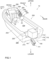
- FIG. 1 is a perspective view schematically illustrating a configuration of a boat 10 of this embodiment.
- FIG. 1 and other drawings described below show arrows representing each direction with respect to the position of the boat 10. More specifically, each drawing shows arrows representing the front direction (FRONT), rear direction (REAR), left direction (LEFT), right direction (RIGHT), upper direction (UPPER), and lower direction (LOWER), respectively.
- the front-rear direction, left-right direction, and upper-lower direction are orthogonal to each other. It should be noted that, in this specification, axes, members, and the like extending in the front-rear direction need not necessarily be parallel to the front-rear direction.
- Axes and members extending in the front-rear direction include axes and members inclined within the range of ⁇ 45° to the front-rear direction.
- axes and members extending in the upper-lower direction include axes and members inclined within a range of ⁇ 45° to the upper-lower direction
- axes and members extending in the left-right direction include axes and members inclined within a range of ⁇ 45° to the left-right direction.
- the boat 10 includes a hull 200 and an outboard motor 100.
- the boat 10 has only one outboard motor 100, but the boat 10 may have multiple outboard motors 100.
- the hull 200 is a part of the boat 10 for occupants to ride.
- the hull 200 includes a hull main body 202 including a living space 204, a pilot seat 240 installed in the living space 204, and an operating device 250 installed near the pilot seat 240.
- the operating device 250 is a device for steering the boat and includes, e.g., a steering wheel 252, a shift/throttle lever 254, a joystick 255, a monitor 256, and an input device 258.
- the hull 200 includes a partition wall 220 to partition the rear end of the living space 204 and a transom 210 disposed at the rear end of the hull 200. In the front-rear direction, a space 206 is provided between the transom 210 and the partition wall 220.
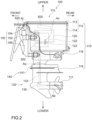
- FIG. 2 is a side view schematically illustrating a configuration of an outboard motor 100 of this embodiment.
- the outboard motor 100 in the reference attitude will be described below unless otherwise specified.
- the reference attitude is an attitude in which the rotation axis Ac of the output shaft 123, which will be described later, extends in the upper-lower direction, and the rotation axis Ap of the propeller shaft 135, which will be described later, extends in the front-rear direction.
- the front-rear direction, the left-right direction, and the upper-lower direction are respectively defined based on the outboard motor 100 in the reference attitude.
- the outboard motor 100 is a device that generates thrust to propel the boat 10.
- the outboard motor 100 is attached to the transom 210 at a rear portion of the hull 200.
- the outboard motor 100 includes an outboard motor main body 110 and a suspension device 150.
- the outboard motor main body 110 includes a waterproof case 112, a middle case 116, a lower case 118, a motor assembly 120, a control assembly 500, a transmission mechanism 130, a propeller 111, and a steering mechanism 140.
- the waterproof case 112 is a housing located at an upper portion of the outboard motor main body 110.
- the waterproof case 112 houses an electric motor 122 described below and other electrical components to protect the electric motor 122 and electrical components from being exposed to seawater.
- the waterproof case 112 includes an upper cover 113 constituting the upper part of the waterproof case 112 and a lower box 114 constituting the lower part of the waterproof case 112.
- the lower box 114 has a box-shaped configuration with an open top.
- the upper cover 113 is removably attached to the lower box 114 to cover the top portion (opening) of the lower box 114.
- the middle case 116 is a housing located below the waterproof case 112 and arranged near the center of the outboard motor main body 110 in the upper-lower direction. The upper part of the middle case 116 is connected to the lower box 114 of the waterproof case 112.
- the lower case 118 is a housing located below the middle case 116 and arranged at the bottom of the outboard motor main body 110.
- the motor assembly 120 is housed inside the waterproof case 112.
- the motor assembly 120 includes an electric motor 122 as a driving source.
- the electric motor 122 is a prime mover that generates power.
- the electric motor 122 has an output shaft 123 that outputs the driving force generated by the electric motor 122.
- the output shaft 123 is arranged in an attitude in which its rotation axis Ac extends in the upper-lower direction.
- the control assembly 500 is housed inside the waterproof case 112 and is arranged at a position higher than the motor assembly 120.
- the control assembly 500 controls the rotation of the electric motor 122 and the like.
- the transmission mechanism 130 transmits the driving force of the electric motor 122 to the propeller 111.
- the transmission mechanism 130 includes a primary reduction gear 300, a drive shaft 133, and a propeller shaft 135.
- the primary reduction gear 300 is housed inside the waterproof case 112 and is arranged at a position lower than the motor assembly 120.
- the primary reduction gear 300 is connected to the output shaft 123 of the electric motor 122 and the drive shaft 133.
- the primary reduction gear 300 reduces the driving force of the electric motor 122 and transmits it to the drive shaft 133. This allows the propeller 111 to rotate at a desired torque.
- the drive shaft 133 is a rod-shaped member that transmits power to the propeller shaft 135 and is arranged in an attitude extending in the upper-lower direction.
- the drive shaft 133 is housed so that it spans the inside of the waterproof case 112, the inside of the middle case 116, and the inside of the lower case 118.
- the propeller shaft 135 is a rod-shaped member that is arranged in an attitude extending in the front-rear direction at a height relatively lower than the outboard motor main body 110.
- the propeller shaft 135 rotates together with the propeller 111.
- the front end of the propeller shaft 135 is housed in the lower case 118, and the rear end of the propeller shaft 135 protrudes rearward from the lower case 118.
- a gear is provided at the lower end portion of the drive shaft 133 and at the front end portion of the propeller shaft 135, respectively.
- the rotation of the drive shaft 133 is transmitted to the propeller shaft 135 by meshing the gears of the drive shaft 133 and the propeller shaft 135.
- the propeller 111 is a rotating member with multiple blades and is attached to the rear end of the propeller shaft 135.
- the propeller 111 rotates along with the rotation of the propeller shaft 135 about the rotation axis Ap.
- the propeller 111 generates thrust to propel the boat 10 by rotating.
- the steering mechanism 140 is a mechanism that controls changes in the traveling direction of the boat 10.
- the steering mechanism 140 has a steering shaft 141.
- the steering shaft 141 is a hollow tubular member arranged to surround the outer circumference of the drive shaft 133. At least a part of the steering shaft 141 is housed in the middle case 116 and is supported so as to be rotatable about the rotation axis As.
- the lower portion of the steering shaft 141 protrudes downward from the middle case 116 and is connected to the lower case 118.
- the steering shaft 141 rotates about the rotation axis As, for example, by the driving force of the drive motor (not shown) housed in the middle case 116.
- the lower case 118 connected to the steering shaft 141 also rotates, and the direction of the propeller 111 is changed. This changes the direction of the thrust generated by the propeller 111 to enable the steering of the boat 10.
- the suspension device 150 is a device to suspend the outboard motor main body 110 to the hull 200.
- the suspension device 150 includes a pair of left and right clamp brackets 152, a tilt shaft 154, and a swivel bracket 156.
- the pair of left and right clamp brackets 152 are disposed behind the hull 200 in a state separated from each other in the left-right direction and are fixed to the transom 210 of the hull 200 by using, e.g., bolts.
- the tilt shaft 154 is a rod-shaped member and is rotatably supported by the clamp brackets 152.
- the tilt axis At which is the center line of the tilt shaft 154, constitutes the horizontal (left-right) axis of the outboard motor 100 during tilting.
- the swivel bracket 156 is disposed so as to be sandwiched between the pair of clamp brackets 152 and is supported by the clamp brackets 152 via the tilt shaft 154 so as to be rotatable about the tilt axis At.
- the swivel bracket 156 is driven to rotate about the tilt axis At relative to the clamp bracket 152 by a tilting device (not shown) that includes an actuator such as a hydraulic cylinder.
- the outboard motor main body 110 supported by the swivel bracket 156 also rotates about the tilt axis At. This achieves the tilting operation of rotating the outboard motor main body 110 in the upper-lower direction with respect to the hull 200.
- the outboard motor 100 can change the angle of the outboard motor main body 110 about the tilt axis At in the range from the tilt-down state in which the propeller 111 is disposed under the water (the state in which the outboard motor 100 is in the reference attitude) to the tilt-up state in which the propeller 111 is disposed above the water surface. Trimming operation for adjusting the attitude of the boat 10 during travel can also be performed by adjusting the angle about the tilt axis At of the outboard motor main body 110.
- FIG. 3 is an explanatory view schematically illustrating part of the internal configuration of the outboard motor main body 110.
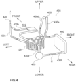
- FIG. 4 is an explanatory view schematically illustrating the configuration of an overall coolant flow path 400.
- FIGS. 3 and 4 show the internal structure housed inside the waterproof case 112. As shown in FIGS. 3 and 4 , the outboard motor 100 is provided with an overall coolant flow path 400, which is a series of flow paths through which coolant liquid C circulates.
- the coolant liquid C circulates inside the outboard motor main body 110 to cool the electric motor 122 and the MCU 510 described below.
- the coolant liquid C is an antifreeze solution mainly composed of, e.g., ethylene glycol or propylene glycol.
- the coolant liquid C is an example of the coolant.
- the control assembly 500 includes a control case 502, a motor control unit (MCU) 510, and a power supply line 520 (see FIG. 2 ).
- the MCU 510 is a circuit board that controls the rotation of the electric motor 122 and the like.
- the control case 502 houses the MCU 510. Inside the control case 502, there is a space 512 that is a flow path for the coolant liquid C. In other words, the overall coolant flow path 400 includes the space 512 formed inside the control case 502.
- the power supply line 520 supplies power to the MCU 510 from a battery or the like (not shown) installed in the hull 200.
- the outboard motor 100 further includes a motor cooling device 126, an air vent 420, a filler 450, a heat exchanger 440, a pump 410, and multiple coolant tubes 430a to 430f.
- the motor cooling device 126 has a ring-shaped configuration when viewed in the upper-lower direction and is arranged to surround the outer circumference of the electric motor 122. Inside the motor cooling device 126, a space is formed that is a flow path for the coolant liquid C. In other words, the overall coolant flow path 400 includes the space formed inside the motor cooling device 126.
- the air vent 420 includes an opening for releasing air that has mixed into the overall coolant flow path 400 to the atmosphere. By removing air from the overall coolant flow path 400, the air vent 420 improves the cooling efficiency of the electric motor 122 and the MCU 510.
- the air vent 420 is located at an uppermost portion of the overall coolant flow path 400.
- the filler 450 includes an opening that functions as a filling port for the coolant liquid C in the overall coolant flow path 400.
- the opening of the filler 450 also has a function for releasing air that has mixed into the overall coolant flow path 400 to the atmosphere.
- the filler 450 is located at a relatively higher position in the overall coolant flow path 400, and more specifically, it is located at a position higher than the electric motor 122 and the motor cooling device 126.
- the heat exchanger 440 is a device in which heat exchange occurs between the coolant liquid C and seawater that is pumped up from outside the outboard motor 100 by a pump (not shown).
- the coolant liquid C becomes relatively hot as it passes near the electric motor 122 and the MCU 510 and is cooled by exchanging heat with seawater in the heat exchanger 440.
- the detailed configuration of the heat exchanger 440 is described below.
- the pump 410 is a device that pumps the coolant liquid C.
- the pump 410 is connected to the coolant tube 430a described below and the coolant tube 430f described below.
- the coolant liquid C circulates through the overall coolant flow path 400 by the operation of the pump 410.
- the pump 410 is located at a relatively lower position in the overall coolant flow path 400, and more specifically, it is located at a height lower than the MCU 510 and the control case 502.
- the multiple coolant tubes 430a to 430f are tubular members that are hollow from one end to the other end, and the space formed inside each of them forms at least a part of the overall coolant flow path 400.
- Each of the coolant tubes 430a to 430f is configured such that the coolant liquid C flows from one end to the other end by the operation of the pump 410.
- the coolant tube 430a forms a portion of the overall coolant flow path 400 that extends from the pump 410 to the control case 502.
- One end of the coolant tube 430a is connected to the pump 410 to communicate with the flow path of the coolant liquid C formed in the pump 410.
- the other end of the coolant tube 430a is connected to the control case 502 to communicate with the space 512 of the control case 502.
- the coolant tube 430b forms a portion of the overall coolant flow path 400 that extends from the control case 502 to the air vent 420.
- One end of the coolant tube 430b is connected to the control case 502 to communicate with the space 512 of the control case 502.
- the other end of the coolant tube 430b is connected to the end of one end of the coolant tube 430c to communicate with the coolant tube 430c.
- the lower end of the coolant tube 430b (the lowest part of the coolant tube 430b) is the connection position with the control case 502.
- the coolant tube 430c forms a portion of the overall coolant flow path 400 that extends from the air vent 420 to the motor cooling device 126.
- One end of the coolant tube 430c is connected to the air vent 420.
- the other end of the coolant tube 430c is connected to the motor cooling device 126 to communicate with the space formed inside the motor cooling device 126.
- the coolant tube 430d forms a portion of the overall coolant flow path 400 that extends from the motor cooling device 126 to the filler 450.
- One end of the coolant tube 430d is connected to the motor cooling device 126 to communicate with the space formed inside the motor cooling device 126.
- the other end of the coolant tube 430d is connected to the end of one end of the coolant tube 430e to communicate with the coolant tube 430e.
- the lower end of the coolant tube 430d (the lowest portion in the coolant tube 430d) is the connection position with the motor cooling device 126.
- the coolant tube 430e forms a portion of the overall coolant flow path 400 that extends from the filler 450 to the heat exchanger 440.
- One end of the coolant tube 430e is connected to the filler 450.
- the other end of the coolant tube 430e is connected to the heat exchanger 440 to communicate with the flow path of the coolant liquid C formed in the heat exchanger 440.
- the coolant tube 430f forms a portion of the overall coolant flow path 400 that extends from the heat exchanger 440 to the pump 410.
- One end of the coolant tube 430f is connected to the heat exchanger 440 to communicate with the flow path of the coolant liquid C formed in the heat exchanger 440.
- the other end of the coolant tube 430f is connected to the pump 410 to communicate with the flow path of the coolant liquid C formed in the pump 410.
- the overall coolant flow path 400 is configured such that the coolant liquid C pumped by the pump 410 flows in the order of the MCU 510, the air vent 420, the motor cooling device 126, the filler 450, and the heat exchanger 440, and then circulates back to the pump 410.
- the coolant liquid C flows out of the pump 410, passes through the coolant tube 430a, and flows into space 512.
- the coolant liquid C that flows into space 512 flows near the MCU 510 to cool the MCU 510.
- the coolant liquid C flows out of the space 512, passes through the coolant tube 430b, and flows into the coolant tube 430c to flow near the air vent 420. If air has been mixed into the coolant liquid C at this time, the air flows towards the air vent 420, which is located at a position higher than the connection position between the coolant tubes 430b, 430c and is released to the atmosphere via the air vent 420 (arrow A in FIGS. 3 and 4 ).
- the coolant liquid C passes through the coolant tube 430c and flows into the space formed inside the motor cooling device 126.
- the coolant liquid C that flows into the space formed inside the motor cooling device 126 flows near the electric motor 122 to cool the electric motor 122.
- the coolant liquid C flows out of the space formed inside the motor cooling device 126, passes through the coolant tube 430d, and flows into the coolant tube 430e to flow near the filler 450. If air has been mixed into the coolant liquid C at this time, the air flows towards the filler 450, which is located at a position higher than the connection position between the coolant tubes 430d and 430e, and is released to the atmosphere via the filler 450 (arrow A in FIGS. 3 and 4 ).
- the coolant liquid C passes through the coolant tube 430e and flows into the heat exchanger 440.
- the coolant liquid C is cooled by exchanging heat with seawater pumped in from outside the outboard motor 100.
- the coolant liquid C flows out of the heat exchanger 440, passes through the coolant tube 430f, and flows into the pump 410.
- the coolant liquid C circulates through the overall coolant flow path 400.
- FIG. 5 is an exploded view illustrating the heat exchanger 440.
- the heat exchanger 440 is disposed, e.g., on a side of the motor assembly 120.
- the heat exchanger 440 has a water channel body 442W, a coolant channel body 442C, and a heat exchange plate 444.
- a water flow path 600W is formed inside the water channel body 442W, through which seawater W flows.
- a coolant flow path 600C is formed through which coolant liquid C flows (see FIG. 6 below).
- the heat exchange plate 444 is positioned between the water channel body 442W and the coolant channel body 442C to perform heat exchange between the water channel body 442W and the coolant channel body 442C.
- the heat exchange plate 444 is a flat plate-shaped member disposed orthogonally to the facing direction of the water channel body 442W and the coolant channel body 442C and is formed of a material with high thermal conductivity, such as, e.g., metal.
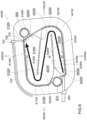
- FIG. 6 is an explanatory view illustrating a detailed configuration of a water channel body 442W.
- the water channel body 442W as a whole has a substantially flat plate shape.
- FIG. 6 shows the configuration of the inner side 441W of the water channel body 442W that faces the heat exchange plate 444.
- a groove constituting the water flow path 600W is formed in this inner side 441W, and the heat exchange plate 444 is arranged to cover the inner side 441W including this groove.
- the water flow path 600W is composed of the groove formed in the water channel body 442W and the left surface of the heat exchange plate 444, and the seawater W circulating in the water flow path 600W is in direct contact with the heat exchange plate 444.
- the groove formed in the water channel body 442W may hereinafter be referred to as the water flow path 600W.
- the water flow path 600W is an S-shaped flow path as a whole and includes an upper flow path portion 610W, a middle flow path portion 620W, a lower flow path portion 630W, an upper folded portion 615W, and a lower folded portion 625W.
- the upper flow path portion 610W is an example of the first flow path portion
- the middle flow path portion 620W is an example of the second and fourth flow path portions
- the lower flow path portion 630W is an example of the third flow path portion.
- the upper folded portion 615W is an example of the first folded portion
- the lower folded portion 625W is an example of the second folded portion.
- the upper flow path portion 610W is located at the uppermost level in the water flow path 600W and extends in a substantially straight line in a direction intersecting the upper-lower direction (substantially horizontal direction).
- the lower flow path portion 630W is located at the lowermost level in the water flow path 600W and extends in a substantially straight line in a direction intersecting the upper-lower direction (substantially horizontal direction).
- the middle flow path portion 620W is located between the upper flow path portion 610W and the lower flow path portion 630W in the upper-lower direction and extends in a substantially straight line in a direction intersecting the upper-lower direction (substantially horizontal direction).
- the upper flow path portion 610W, the middle flow path portion 620W, and the lower flow path portion 630W are arranged to overlap each other when viewed in the upper-lower direction.
- the upper folded portion 615W connects the ends (rear ends) of the upper flow path portion 610W and the middle flow path portion 620W on the same directional side.
- the outer circumference 617W of the upper folded portion 615W is arcuate.
- the lower folded portion 625W connects the ends (front ends) of the middle flow path portion 620W and the lower flow path portion 630W on the same directional side.
- the outer circumference 627W of the lower folded portion 625W is arcuate.
- the upper flow path portion 610W is provided with an outlet hole 612W that is connected to the outside of the heat exchanger 440.
- the outlet hole 612W is connected to a discharge tube (not shown) to discharge the seawater W to the outside of the outboard motor 100.
- Ceiling surfaces 614W, 616W forming the upper flow path portion 610W are inclined upward at an angle toward the outlet hole 612W.
- the outlet hole 612W is an example of the first connecting hole. Specifically, the outlet hole 612W is located at the highest position in the water flow path 600W and is formed to penetrate from the groove described above constituting the water flow path 600W to an outer side 443W of the water channel body 442W. In other words, the outlet hole 612W faces the ceiling surfaces 614W, 616W.
- the outlet hole 612W is formed on the end (front end) opposite to the upper folded portion 615W.
- the first ceiling surface 614W is inclined continuously and linearly upward at an angle from a position adjacent to the outer circumference 617W of the upper folded portion 615W toward the outlet hole 612W.
- the second ceiling surface 616W is located opposite the first ceiling surface 614W with respect to the outlet hole 612W and is inclined continuously and linearly upward at an angle toward the outlet hole 612W.
- the slope of the first ceiling surface 614W e.g., the inclination angle ⁇ 1 is 5 degrees or more
- the ceiling surface 622W of the middle flow path portion 620W is inclined upward at an angle toward the upper folded portion 615W.
- the bottom surface 618W of the upper flow path portion 610W is inclined downward at an angle from the upper folded portion 615W along the ceiling surface 622W of the middle flow path portion 620W.
- the lower end portion of the bottom surface 618W is provided with a first through hole 640W that penetrates to the ceiling surface 622W of the middle flow path portion 620W.
- the bottom surface 618W is an example of the first inclined surface portion.
- the upper flow path portion 610W and the middle flow path portion 620W are separated by a first partition wall 619W.
- the first partition wall 619W is straight and inclined to be positioned upward as it approaches the upper folded portion 615W when viewed in the left-right direction.
- the lower end portion of the first partition wall 619W is provided with a first through hole 640W.
- the lower flow path portion 630W is provided with an inlet hole 642W that is connected to the outside of the heat exchanger 440.
- the inlet hole 642W is formed on the end (rear end) opposite to the lower folded portion 625W.
- the bottom surface 634W of the lower flow path portion 630W is inclined downward at an angle toward the inlet hole 642W.
- the slope of the bottom surface 634W (e.g., the inclination angle ⁇ 2 is 5 degrees or more) is identical to the slope of the first ceiling surface 614W of the upper flow path portion 610W described above.
- the inlet hole 642W is connected to a supply tube 680 through which the seawater W pumped by the above-mentioned pump is distributed.
- the inlet hole 642W is an example of the second connecting hole and the supply tube 680 is an example of the water tube.
- the ceiling surface 632W of the lower flow path portion 630W is inclined upward at an angle toward the lower folded portion 625W.
- the bottom surface 624W of the middle flow path portion 620W is inclined downward at an angle from the lower folded portion 625W along the ceiling surface 632W of the lower flow path portion 630W.
- the lower end portion of the bottom surface 624W is provided with a second through hole 650W that penetrates to the ceiling surface 632W of the lower flow path portion 630W.
- the bottom surface 624W is an example of the second inclined surface portion.
- the lower flow path portion 630W and the middle flow path portion 620W are separated by a second partition wall 629W.
- the second partition wall 629W is straight and inclined to be positioned upward as it approaches the lower folded portion 625W when viewed in the left-right direction.
- the lower end portion of the second partition wall 629W is provided with a second through hole 650W.
- FIG. 7 is an explanatory view illustrating a detailed configuration of a coolant channel body 442C.
- the coolant channel body 442C as a whole has a substantially flat plate shape.
- FIG. 7 shows the configuration of the inner side 441C of the coolant channel body 442C that faces the heat exchange plate 444.
- a groove constituting the coolant flow path 600C is formed in this inner side 441C, and the heat exchange plate 444 is arranged to cover the inner side 441C including this groove.
- the coolant flow path 600C is composed of the groove formed in the coolant channel body 442C and the right side of the heat exchange plate 444, and the coolant liquid C circulating in the coolant flow path 600C is in direct contact with the heat exchange plate 444.
- the groove formed in the coolant channel body 442C may hereinafter be referred to as the coolant flow path 600C.
- a plurality of cooling fins F are provided on the outer side 443C of the coolant channel body 442C (see FIG. 5
- the coolant flow path 600C is an S-shaped flow path as a whole and includes an upper flow path portion 610C, a middle flow path portion 620C, a lower flow path portion 630C, an upper folded portion 615C, and a lower folded portion 625C.
- the upper flow path portion 610C is an example of the first flow path portion
- the middle flow path portion 620C is an example of the second and fourth flow path portions
- the lower flow path portion 630C is an example of the third flow path portion.
- the upper folded portion 615C is an example of the first folded portion
- the lower folded portion 625C is an example of the second folded portion.
- the upper flow path portion 610C is located at the uppermost level in the coolant flow path 600C and extends in a substantially straight line in a direction intersecting the upper-lower direction (substantially horizontal direction).
- the lower flow path portion 630C is located at the lowermost level in the coolant flow path 600C and extends in a substantially straight line in a direction intersecting the upper-lower direction (substantially horizontal direction).
- the middle flow path portion 620C is located between the upper flow path portion 610C and the lower flow path portion 630C in the upper-lower direction and extends in a substantially straight line in a direction intersecting the upper-lower direction (substantially horizontal direction).
- the upper flow path portion 610C, the middle flow path portion 620C, and the lower flow path portion 630C are arranged to overlap each other when viewed in the upper-lower direction.
- the upper folded portion 615C connects the ends (rear ends) of the upper flow path portion 610C and the middle flow path portion 620C on the same directional side.
- the outer circumference 617C of the upper folded portion 615C is arcuate.
- the lower folded portion 625C connects the ends (front ends) of the middle flow path portion 620C and the lower flow path portion 630C on the same directional side.
- the outer circumference 627C of the lower folded portion 625C is arcuate.
- the upper flow path portion 610C is provided with an inlet hole 612C that is connected to the outside of the heat exchanger 440.
- a ceiling surface 614C forming the upper flow path portion 610C is inclined upward at an angle toward the inlet hole 612C.
- the inlet hole 612C is an example of the first connecting hole. Specifically, the inlet hole 612C is located at the highest position in the coolant flow path 600C and is formed to penetrate the heat exchange plate 444 constituting the coolant flow path 600C (see FIG. 5 ).
- the inlet hole 612C is connected to the coolant tube 430e described above.
- the heat exchange plate 444 has a tubular portion 446 protruding toward the water channel body 442W, and the inlet hole 612C is connected to this tubular portion 446.
- the tubular portion 446 is connected to the coolant tube 430e via an insertion hole 660 formed in the water channel body 442W.
- the inlet hole 612C is formed on the end (front end) opposite to the upper folded portion 615C.
- the ceiling surface 614C is inclined continuously and linearly upward at an angle from a position adjacent to the outer circumference 617C of the upper folded portion 615C to the inlet hole 612C.
- the side surface 616C constituting the coolant flow path 600C is also inclined continuously and linearly upward at an angle toward the inlet hole 612C.
- the slope of the ceiling surface 614C e.g., the inclination angle ⁇ 1 is 5 degrees or more
- the upper flow path portion 610C and the middle flow path portion 620C are separated by the first partition wall 619C.
- the first partition wall 619C is straight and inclined to be positioned upward as it approaches the upper folded portion 615C when viewed in the left-right direction.
- the lower end portion of the first partition wall 619C is provided with a first through hole 640C.
- the lower flow path portion 630C is provided with an outlet hole 642C that is connected to the outside of the heat exchanger 440 and a coolant drain hole 660C that is connected to the outside of the heat exchanger 440.
- the outlet hole 642C and the coolant drain hole 660C are formed on the end (rear end) opposite to the lower folded portion 625C.
- the coolant drain hole 660C is located at a position lower than the outlet hole 642C.
- the bottom surface 634C of the lower flow path portion 630C is inclined downward at an angle toward the coolant drain hole 660C.
- the slope of the bottom surface 634C (e.g., the inclination angle ⁇ 2 is 5 degrees or more) is identical to the slope of the ceiling surface 614C of the upper flow path portion 610C described above.
- the coolant drain hole 660C is used to discharge the coolant liquid C in the coolant flow path 600C.
- the outlet hole 642C is connected to the coolant tube 430f described above.
- the heat exchange plate 444 has a tubular portion 448 protruding toward the water channel body 442W, and the outlet hole 642C is connected to this tubular portion 448.
- the tubular portion 448 is connected to the coolant tube 430f via an insertion hole 670 formed in the water channel body 442W.
- the coolant drain hole 660C is an example the second connecting hole.
- the ceiling surface 632C of the lower flow path portion 630C is inclined upward at an angle toward the lower folded portion 625C.
- the bottom surface 624C of the middle flow path portion 620C is inclined downward at an angle from the lower folded portion 625C along the ceiling surface 632C of the lower flow path portion 630C.
- the lower end portion of the bottom surface 624C is provided with a second through hole 650C that penetrates to the ceiling surface 632C of the lower flow path portion 630C.
- the bottom surface 624C is an example of the second inclined surface portion.
- the lower flow path portion 630C and the middle flow path portion 620C are separated by a second partition wall 629C.
- the second partition wall 629C is straight and inclined to be positioned upward as it approaches the lower folded portion 625C when viewed in the left-right direction.
- the lower end portion of the second partition wall 629C is provided with a second through hole 650C.
- the water flow path 600W and the coolant flow path 600C have a substantially identical shape (S-shape) when viewed in the left-right direction.
- the water channel body 442W further includes a secondary discharge tube 700 (see FIGS. 5 and 6 ).
- the secondary discharge tube 700 has an inner tube 702 and an outer tube 704.
- the inner tube 702 is a portion formed inside the heat exchanger 440 (the water channel body 442W).
- the inner tube 702 extends continuously upward from the highest position in the water flow path 600W (the top of the ceiling surfaces 614W, 616W) and penetrates the outer circumference of the water channel body 442W.
- the outer tube 704 is the portion disposed outside of the heat exchanger 440 (the water channel body 442W).
- One end of the outer tube 704 is connected to the inner tube 702 through a connecting member 706.
- the other end of the outer tube 704 opens to an atmospheric space outside the heat exchanger 440.
- the outer tube 704 is arranged to become continuously lower as it approaches the other end that opens from one end connected to the connecting member 706.
- the secondary discharge tube 700 includes a portion (the connecting member 706) that is positioned higher than the outlet hole 612W and further includes a discharging part (the inner tube 702) that opens into the water flow path 600W with that portion as the highest position and a discharging part (the outer tube 704) that opens into the atmospheric space with that portion as the highest position.
- the water flow path 600W is an S-shaped flow path as a whole and includes the upper flow path portion 610W, the middle flow path portion 620W, the lower flow path portion 630W, the upper folded portion 615W, and the lower folded portion 625W (see FIG. 6 ). Therefore, according to this embodiment, the efficiency of heat exchange in the heat exchanger 440 can be improved by the amount of the seawater W circulating in the heat exchanger 440 compared to a configuration in which the water flow path 600W has, e.g., a straight shape as a whole.
- the ceiling surface 622W of the middle flow path portion 620W is inclined upward at an angle toward the upper folded portion 615W (see FIG. 6 ). This suppresses air from being trapped in the middle flow path portion 620W.
- the ceiling surface 632W of the lower flow path portion 630W is inclined upward at an angle toward the lower folded portion 625W (see FIG. 6 ). This can suppress air from being trapped in the lower flow path portion 630W.
- the ceiling surfaces 622W, 632W of the second and the lower flow path portions 620W, 630W from the top in the water flow path 600W are all inclined upward at an angle toward the folded portions 615W, 625W.
- the water channel body 442W allows the seawater W pumped into the supply tube 680 to flow through the inlet hole 642W formed at the lower end portion of the water flow path 600W, and the seawater W accumulates in the water flow path 600W in the order of the lower flow path portion 630W, the middle flow path portion 620W, and the upper flow path portion 610W.
- the ceiling surfaces 614W, 616W forming the upper flow path portion 610W are inclined upward at an angle toward the outlet hole 612W, and the ceiling surfaces 622W, 632W of the flow path portions 620W, 630W of the second and lower stages are all inclined upward at an angle toward the folded portions 615W, 625W. Therefore, during operation of the heat exchanger 440, air is suppressed from being trapped in the water flow path 600W, and the entire water flow path 600W can be filled with the seawater W.
- the outlet hole 612W is formed on the end (front end) opposite to the upper folded portion 615W (see FIG. 6 ). That is, the outlet hole 612W is formed at a high position in the upper folded portion 615W (the water flow path 600W). Therefore, according to this embodiment, the outlet hole 612W can be diverted as an air vent hole without providing a separate hole.
- the bottom surface 634W of the lower flow path portion 630W is inclined downward at an angle toward the inlet hole 642W (see FIG. 6 ).
- This embodiment can suppress the seawater W from remaining in the lower flow path portion 630W compared to, e.g., a configuration in which the bottom surface of the lower flow path portion 630W extends along a horizontal direction or a configuration in which the bottom surface is inclined downward toward a closed portion different from the inlet hole 642W.
- the bottom surface 618W of the upper flow path portion 610W is inclined downward along the ceiling surface 622W of the middle flow path portion 620W from the upper folded portion 615W.
- the lower end portion of the bottom surface 618W is provided with the first through hole 640W that penetrates to the ceiling surface 622W of the middle flow path portion 620W (see FIG. 6 ). Therefore, this embodiment can increase the capacity of the upper flow path portion 610W to accommodate the seawater W while suppressing the seawater W from remaining in the upper flow path portion 610W when the heat exchanger 440 is stopped compared to a configuration in which the bottom surface of the upper flow path portion 610W is inclined upward at an angle from the upper folded portion 615W.
- the bottom surface 624W of the middle flow path portion 620W is inclined downward at an angle from the lower folded portion 625W to the ceiling surface 632W of the lower flow path portion 630W.
- the lower end portion of the bottom surface 624W is provided with the second through hole 650W that penetrates to the ceiling surface 632W of the lower flow path portion 630W (see FIG. 6 ).
- This embodiment can increase the capacity of the middle flow path portion 620W to accommodate the seawater W while suppressing the seawater W from remaining in the middle flow path portion 620W when heat exchanger 440 is stopped.
- the water channel body 442W is configured so that the seawater W accumulated in the water flow path 600W escapes from the upper flow path portion 610W, the middle flow path portion 620W, and the lower flow path portion 630W, in that order.
- the bottom surface 634W of the lower flow path portion 630W is inclined downward at an angle toward the inlet hole 642W.
- the bottom surfaces 618W, 624W of the second and higher level flow path portions 610W, 620W from the bottom are inclined downward at an angle along the ceiling surfaces 622W, 632W of the flow path portions 620W, 630W one level below the folded portion 615W, 625W.
- the lower end portion of bottom surfaces 618W, 624W are provided with the through holes 640W and 650W. This suppresses the seawater W from remaining in the water flow paths 600W when the heat exchanger 440 is stopped.
- FIG. 8 is an explanatory view of the action of a secondary discharge tube 700.
- the heat exchanger 440 includes the secondary discharge tube 700.
- the secondary discharge tube 700 opens from the inside of the water flow path 600W to the atmospheric space outside the heat exchanger 440, and thus, together with the discharge tube, functions as an air vent that discharges the air E, which is trapped in the upper portion of the water flow path 600W, to the outside of the heat exchanger 440. Therefore, compared to the configuration where the heat exchanger 440 does not have the secondary discharge tube 700, the air E in the water flow path 600W can be smoothly discharged to the outside.
- the seawater W is discharged from the water flow path 600W at a high speed compared to a configuration in which the heat exchanger 440 does not have the secondary discharge tube 700.
- the seawater W can be suppressed from remaining in the water flow path 600W.
- the coolant flow path 600C is an S-shaped flow path as a whole and includes the upper flow path portion 61 0C, the middle flow path portion 620C, the lower flow path portion 630C, the upper folded portion 615C, and the lower folded portion 625C (see FIG. 7 ). Therefore, according to this embodiment, the efficiency of heat exchange in the heat exchanger 440 can be improved by the amount of the coolant liquid C circulating in the heat exchanger 440 compared to a configuration in which the coolant flow path 600C has, e.g., a straight shape as a whole, for example.
- the upper flow path portion 610C is provided with the inlet hole 612C that is connected to the outside of the heat exchanger 440.
- the ceiling surface 614C forming the upper flow path portion 610C is inclined upward at an angle toward the inlet hole 612C. Therefore, this embodiment can suppress air from being trapped in the upper flow path portion 610C compared to, e.g., a configuration in which the ceiling surface forming the upper flow path portion 610C extends along a horizontal direction or a configuration in which the ceiling surface is inclined upward at an angle toward a closed portion different from the inlet hole 612C.
- the ceiling surface 622C of the middle flow path portion 620C is inclined upward at an angle toward the upper folded portion 615C (see FIG. 7 ). This suppresses air from being trapped in the middle flow path portion 620C.
- the ceiling surface 632C of the lower flow path portion 630C is inclined upward at an angle toward the lower folded portion 625C (see FIG. 7 ). This suppresses air from being trapped in the lower flow path portion 630C.
- the ceiling surfaces 622C, 632C of the second or lower flow path portions 620C, 630C from the top in the coolant flow path 600C are all inclined upward at an angle toward the folded portions 615C, 625C.
- the inlet hole 612C is formed on the end (front end) opposite to the upper folded portion 615C (see FIG. 7 ). That is, the inlet hole 612C is formed at a high position in the upper folded portion 615C (the coolant flow path 600C). Therefore, according to this embodiment, the inlet hole 612C can be diverted as an air vent hole without providing a separate hole.
- the bottom surface 634C of the lower flow path portion 630C is inclined downward at an angle toward the coolant drain hole 660C (see FIG. 7 ). This embodiment can suppress the coolant liquid C from remaining in the lower flow path portion 630C when the coolant liquid C is discharged.
- the bottom surface 618C of the upper flow path portion 610C is inclined downward at an angle from the upper folded portion 615C to the ceiling surface 622C of the middle flow path portion 620C.
- the lower end portion of the bottom surface 618C is provided with the first through hole 640C that penetrates to the ceiling surface 622C of the middle flow path portion 620C (see FIG. 7 ).
- This embodiment can increase the capacity of the upper flow path portion 610C to accommodate the coolant liquid C while suppressing the coolant liquid C from remaining in the upper flow path portion 610C when the coolant liquid C is discharged.
- the bottom surface 624C of the middle flow path portion 620C is inclined downward at an angle from the lower folded portion 625C to the ceiling surface 632C of the lower flow path portion 630C.
- the lower end portion of the bottom surface 624C is provided with the second through hole 650C that penetrates to the ceiling surface 632C of the lower flow path portion 630C (see FIG. 7 ). Therefore, this embodiment can increase the capacity of the middle flow path portion 620C to accommodate the coolant liquid C while suppressing the coolant liquid C from remaining in the middle flow path portion 620C when the coolant liquid C is discharged.
- this embodiment can improve the heat exchange efficiency of the heat exchanger 440 compared to, e.g., a configuration in which the flow direction of the seawater W in the water flow path 600W and the flow direction of the coolant liquid C in the coolant flow path 600C are the same.
- the configuration of the boat 10 and the outboard motor 100 of the preferred embodiment is an example and may be variously modified.
- the drive source of the above embodiment only includes the electric motor 122.
- the drive source may include both the electric motor and an engine such as an internal combustion engine.
- the MCU 510 is arranged at a position higher than the electric motor 122.
- the MCU may be arranged at a position lower than the electric motor.
- coolant tubes 430a to 430f there are multiple coolant tubes 430a to 430f. Alternatively, only one coolant tube may be provided.
- the water flow path is exemplified by the water flow path 600W formed by a groove formed on the inner side 441W of the water channel body 442W and the heat exchange plate 444.
- the water flow path may be a through channel inside the water channel body 442W.
- the coolant flow path is exemplified by the coolant flow path 600C formed by a groove formed on the inner side 441C of the coolant channel body 442C and the heat exchange plate 444.
- the coolant flow path may be a through channel inside the coolant channel body 442C.
- both the coolant flow path 600C and the water flow path 600W are configured with two folded portions. Alternatively, they may be configured without a folded portion, with one folded portion, or with three or more folded portions.
- the first ceiling surface 614W may be inclined upward in a stepwise or curvilinear manner toward the outlet hole 612W.
- the bottom surface 634W of the lower flow path portion 630W may be inclined upward in a stepwise or curvilinear manner toward the inlet hole 642W.
- the bottom surface 634C of the lower flow path portion 630C may be inclined upward in a stepwise or curvilinear manner toward the coolant drain hole 660C.
- the ceiling surfaces 632W, 632C of the lower flow path portions 630W, 630C may be inclined upward in a stepwise or curvilinear manner toward the lower folded portions 625W, 625C.
- the bottom surfaces 624W, 624C of the middle flow path portions 620W, 620C may be inclined upward in a stepwise or curvilinear manner from the lower folded portions 625W, 625C along the ceiling surfaces 632W, 632C of the lower flow path portions 630W, 630C.
- the first connecting hole is exemplified by the outlet hole 612W and the inlet hole 612C.
- the first connecting hole and may be a through hole that opens into the flow paths (the water flow path 600W, the coolant flow path 600C) at a higher position than the outlet hole 612W and the inlet hole 612C and also opens into the atmospheric space outside the heat exchanger 440.
- the second connecting hole is exemplified by the inlet hole 642W.
- the second connecting hole may be a through hole that opens into the flow path (the water flow path 600W) at a lower position than the inlet hole 642W and also opens into the atmospheric space outside the heat exchanger 440.
- the configuration may be such that the flow direction of the seawater W in the water flow path 600W and the flow direction of the coolant liquid C in the coolant flow path 600C are the same.
- the coolant liquid C (antifreeze mainly composed of ethylene glycol or propylene glycol) is shown as an example coolant.
- another type of coolant may be selected as long as it cools the electric motor and motor control device.
- the water flow path 600W is configured to be filled with the seawater W by allowing the seawater W to flow in through the inlet hole 642W formed at the lower end portion of the water flow path 600W. This allows the water flow path 600W to be filled with the seawater W while suppressing air from being trapped in the water flow path 600W, even in a configuration in which the seawater W is filled into the water flow path 600W every time the outboard motor 100 changes from the tilt-up state to the tilt-down state.
- the configuration may be such that the seawater W is allowed to flow in through holes formed at the upper end portion of the water flow path 600W to fill the water flow path 600W.
- the coolant liquid C flows in from the inlet hole 612C formed at the upper end portion of the coolant flow path 600C.
- the overall coolant flow path 400 is basically sealed, and there is no need to have the coolant liquid C fill the coolant flow path 600C every time the outboard motor 100 changes from the tilt-up state to the tilt-down state.
- the coolant liquid C may flow in through a hole formed in the lower end portion of the coolant flow path 600C.
- the heat exchanger 440 may be configured without a secondary discharge tube 700.
- the secondary discharge tube 700 may be configured without the outer tube 704.
- the inner tube 702 may be configured to extend diagonally upward.
Landscapes
- Engineering & Computer Science (AREA)
- Ocean & Marine Engineering (AREA)
- Chemical & Material Sciences (AREA)
- Combustion & Propulsion (AREA)
- Mechanical Engineering (AREA)
- General Engineering & Computer Science (AREA)
- Heat-Exchange Devices With Radiators And Conduit Assemblies (AREA)
Abstract
Description
- The present invention relates to an outboard motor and a boat.
- A boat includes a hull and an outboard motor mounted to a rear portion of the hull. The outboard motor is a device that generates thrust to propel the boat.
- There has been known an outboard motor having a drive source including an electric motor and a configuration for cooling the drive source. Specifically, the outboard motor is equipped with a coolant tube through which the coolant that cools the drive source flows, a water tube through which external water flows, and a heat exchanger. Inside the heat exchanger are formed a coolant flow path through which the coolant from the coolant tube flows and a water flow path through which the water from the water tube flows. The ceiling surface of the coolant flow path extends horizontally toward the coolant inlet/outlet. The ceiling surface of the water flow path also extends horizontally toward the water inlet/outlet (see, e.g.,
JP 2010-228528 A - As mentioned above, in a conventional heat exchanger provided in an outboard motor, both the ceiling surface of the coolant flow path and the ceiling surface of the water flow path extend horizontally toward the inlet and outlet of the coolant or water, so that air is likely to be trapped in the coolant path and the water flow path. If air is trapped in the coolant or water flow path, the efficiency of the heat exchange in the heat exchanger may decrease because the heat exchange between the coolant and water does not occur in the area where the air is trapped.
- It is the object of the present invention to provide an outboard motor having high efficiency of heat exchange in a heat exchanger while suppressing air from being trapped in the flow path formed inside the heat exchanger.
- According to the present invention said object is solved by an outboard motor having the features of independent claim 1 or 11. Preferred embodiments are laid down in the dependent claims.
- Accordingly, the technology disclosed herein can be implemented in the following aspects.
- An outboard motor disclosed herein includes a drive source including an electric motor, a coolant tube through which a coolant for cooling the drive source flows, a water tube through which water from outside flows, and a heat exchanger having a coolant flow path through which the coolant from the coolant tube flows and a water flow path through which the water from the water tube flows formed therein. at least one of the coolant flow path and the water flow path includes a first flow path portion extending in a direction intersecting an upper-lower direction, a second flow path portion located at a position lower than the first flow path portion and extending in a direction intersecting the upper-lower direction, and a first folded portion connecting one end of the first flow path portion and one end of the second flow path portion. The first flow path portion is provided with a first connecting hole that is connected to the outside of the heat exchanger, and a ceiling surface forming the first flow path portion is inclined upward at an angle toward the first connecting hole.
- In this configuration, since at least one of the coolant flow path and the water flow path is shaped so as to have a folded portion, the efficiency of heat exchange in the heat exchanger can be improved by the amount of fluid circulating in the heat exchanger compared to, e.g., a configuration in which the flow path has a straight shape, for example. In addition, this configuration can suppress air from being trapped in the first flow path portion compared to, e.g., a configuration in which the ceiling surface forming the first flow path portion extends along a horizontal direction or a configuration in which the ceiling surface is inclined upward at an angle toward a closed portion different from the first connecting hole.
- The outboard motor may be configured such that the first connecting hole is an inlet or outlet hole for a fluid, which is the coolant or the water, and is formed at an end of the first flow path portion opposite to the first folded portion. According to this configuration, the fluid inlet or outlet hole can be diverted as an air vent hole without providing a separate hole.
- The outboard motor may be configured such that the ceiling surface of the second flow path portion is inclined upward at an angle toward the first folded portion. This configuration can suppress air from being trapped not only in the first flow path portion but also in the second flow path portion.
- The outboard motor may be configured such that a bottom surface of the first flow path portion is provided with a first inclined surface portion inclined downward at an angle from the first folded portion along the ceiling surface of the second flow path portion, and a lower end portion of the first inclined surface portion is provided with a first through hole that penetrates to the ceiling surface of the second flow path portion. This configuration can increase the capacity of the flow path to accommodate the fluid while suppressing fluid from remaining in the first flow path portion when the heat exchanger is stopped compared to the configuration, e.g., in which the bottom surface of the first flow path portion is inclined upward at an angle from the first folded portion.
- The above outboard motor may be configured such that at least one of the flow paths includes a third flow path portion extending in a direction intersecting the upper-lower direction, a fourth flow path portion located at a position higher than the third flow path portion and extending in a direction intersecting the upper-lower direction, and a second folded portion connecting one end of the third flow path portion and one end of the fourth flow path portion. The third flow path portion may be provided with a second connecting hole at the end opposite to the second folded portion that is connected to the outside, and the bottom surface of the third flow path portion may be inclined downward at an angle toward the second connecting hole. This configuration can suppress fluid (coolant, water) from remaining in the second flow path portion compared to a configuration in which the bottom surface forming the third flow path portion extends along a horizontal direction or a configuration in which the bottom surface is inclined downward at an angle toward a closed portion different from the second connecting hole.
- The outboard motor may be configured such that the ceiling surface of the third flow path portion is inclined upward at an angle toward the second folded portion. This configuration can suppress air from being trapped not only in the first flow path portion but also in the fourth flow path portion.
- The outboard motor may be configured such that a bottom surface of the fourth flow path portion is provided with a second inclined surface portion inclined downward at an angle from the second folded portion along the ceiling surface of the third flow path portion. A lower end portion of the second inclined surface portion may be provided with a second through hole that penetrates to the ceiling surface of the third flow path portion. This configuration can increase the capacity of the flow path to accommodate the fluid while suppressing fluid from remaining in the fourth flow path portion when the heat exchanger is stopped compared to the configuration, e.g., in which the bottom surface of the fourth flow path portion is inclined downward at an angle toward the second folded portion.
- The outboard motor may be configured such that the coolant flow path and the water flow path both have the first flow path portion, the second flow path portion, and the first folded portion. One of the coolant flow path and the water flow path may be configured to allow the coolant to flow from the first flow path portion to the second flow path portion via the first folded portion, and the other of the coolant flow path and the water flow path may be configured to allow the water to flow from the second flow path portion to the first flow path portion via the first folded portion. Since the flowing direction of the fluid is opposite in the coolant flow path and the water flow path, this configuration can improve the heat exchange efficiency of the heat exchanger compared to a configuration in which, e.g., the flowing direction of the fluid is the same in the coolant flow path and the water flow path.
- The outboard motor may be configured such that the water flow path is provided with a water inlet hole at a lower end portion of the water flow path and a water outlet hole at an upper end portion of the water flow path, and the outboard motor may further include: a discharge tube connected to the outlet hole to discharge the water in the water flow path to the outside of the outboard motor; and a secondary discharge tube extending upward from a position higher than the outlet hole in the water flow path and opening to a space outside the heat exchanger. According to this configuration, for example, when the outboard motor is stopped, outside air flows into the water flow path through the secondary discharge tube, allowing the water in the water flow path to be quickly discharged to the outside of the heat exchanger.
- A boat disclosed herein may include a hull and the above outboard motor mounted to a rear portion of the hull. This configuration can suppress air from being trapped in the first flow path portion of the heat exchanger.
- An outboard motor disclosed herein includes a drive source including an electric motor, a coolant tube through which a coolant for cooling the drive source flows, a water tube through which water from outside flows, and a heat exchanger having a coolant flow path through which the coolant from the coolant tube flows and a water flow path through which the water from the water tube flows formed therein. At least one of the coolant flow path and the water flow path is provided with a third connecting hole that is connected to the outside of the heat exchanger, and a ceiling surface forming the flow path is inclined upward at an angle toward the third connecting hole. This outboard motor can suppress air from being trapped in the first flow path portion of the heat exchanger.
- The technology disclosed herein can be implemented in various aspects, including, e.g., an outboard motor, a boat provided with an outboard motor and a hull, among other forms.
- According to this outboard motor, it is possible to improve the efficiency of heat exchange in the heat exchanger while suppressing air from being trapped in the flow path formed inside the heat exchanger.
-
-
FIG. 1 is a perspective view schematically illustrating a configuration of a boat of this embodiment. -
FIG. 2 is a side view schematically illustrating a configuration of an outboard motor of this embodiment. -
FIG. 3 is an explanatory view schematically illustrating part of the internal configuration of the outboard motor main body. -
FIG. 4 is an explanatory view schematically illustrating the configuration of an overall coolant flow path. -
FIG. 5 is an exploded view illustrating the heat exchanger. -
FIG. 6 is an explanatory view illustrating a detailed configuration of a water channel body. -
FIG. 7 is an explanatory view illustrating a detailed configuration of a coolant channel body. -
FIG. 8 is an explanatory view of the action of a secondary discharge tube. -
FIG. 1 is a perspective view schematically illustrating a configuration of aboat 10 of this embodiment.FIG. 1 and other drawings described below show arrows representing each direction with respect to the position of theboat 10. More specifically, each drawing shows arrows representing the front direction (FRONT), rear direction (REAR), left direction (LEFT), right direction (RIGHT), upper direction (UPPER), and lower direction (LOWER), respectively. The front-rear direction, left-right direction, and upper-lower direction are orthogonal to each other. It should be noted that, in this specification, axes, members, and the like extending in the front-rear direction need not necessarily be parallel to the front-rear direction. Axes and members extending in the front-rear direction include axes and members inclined within the range of ±45° to the front-rear direction. Similarly, axes and members extending in the upper-lower direction include axes and members inclined within a range of ±45° to the upper-lower direction, and axes and members extending in the left-right direction include axes and members inclined within a range of ±45° to the left-right direction. - The
boat 10 includes ahull 200 and anoutboard motor 100. In this embodiment, theboat 10 has only oneoutboard motor 100, but theboat 10 may havemultiple outboard motors 100. - The
hull 200 is a part of theboat 10 for occupants to ride. Thehull 200 includes a hullmain body 202 including aliving space 204, apilot seat 240 installed in theliving space 204, and anoperating device 250 installed near thepilot seat 240. The operatingdevice 250 is a device for steering the boat and includes, e.g., asteering wheel 252, a shift/throttle lever 254, ajoystick 255, amonitor 256, and aninput device 258. Thehull 200 includes apartition wall 220 to partition the rear end of theliving space 204 and atransom 210 disposed at the rear end of thehull 200. In the front-rear direction, aspace 206 is provided between thetransom 210 and thepartition wall 220. -
FIG. 2 is a side view schematically illustrating a configuration of anoutboard motor 100 of this embodiment. Theoutboard motor 100 in the reference attitude will be described below unless otherwise specified. The reference attitude is an attitude in which the rotation axis Ac of theoutput shaft 123, which will be described later, extends in the upper-lower direction, and the rotation axis Ap of thepropeller shaft 135, which will be described later, extends in the front-rear direction. The front-rear direction, the left-right direction, and the upper-lower direction are respectively defined based on theoutboard motor 100 in the reference attitude. - The
outboard motor 100 is a device that generates thrust to propel theboat 10. Theoutboard motor 100 is attached to thetransom 210 at a rear portion of thehull 200. Theoutboard motor 100 includes an outboard motormain body 110 and asuspension device 150. - The outboard motor
main body 110 includes awaterproof case 112, amiddle case 116, alower case 118, amotor assembly 120, acontrol assembly 500, atransmission mechanism 130, apropeller 111, and asteering mechanism 140. - The
waterproof case 112 is a housing located at an upper portion of the outboard motormain body 110. Thewaterproof case 112 houses anelectric motor 122 described below and other electrical components to protect theelectric motor 122 and electrical components from being exposed to seawater. Thewaterproof case 112 includes anupper cover 113 constituting the upper part of thewaterproof case 112 and alower box 114 constituting the lower part of thewaterproof case 112. Thelower box 114 has a box-shaped configuration with an open top. Theupper cover 113 is removably attached to thelower box 114 to cover the top portion (opening) of thelower box 114. - The
middle case 116 is a housing located below thewaterproof case 112 and arranged near the center of the outboard motormain body 110 in the upper-lower direction. The upper part of themiddle case 116 is connected to thelower box 114 of thewaterproof case 112. - The
lower case 118 is a housing located below themiddle case 116 and arranged at the bottom of the outboard motormain body 110. - The
motor assembly 120 is housed inside thewaterproof case 112. Themotor assembly 120 includes anelectric motor 122 as a driving source. Theelectric motor 122 is a prime mover that generates power. Theelectric motor 122 has anoutput shaft 123 that outputs the driving force generated by theelectric motor 122. Theoutput shaft 123 is arranged in an attitude in which its rotation axis Ac extends in the upper-lower direction. - The
control assembly 500 is housed inside thewaterproof case 112 and is arranged at a position higher than themotor assembly 120. Thecontrol assembly 500 controls the rotation of theelectric motor 122 and the like. - The
transmission mechanism 130 transmits the driving force of theelectric motor 122 to thepropeller 111. Thetransmission mechanism 130 includes aprimary reduction gear 300, adrive shaft 133, and apropeller shaft 135. - The
primary reduction gear 300 is housed inside thewaterproof case 112 and is arranged at a position lower than themotor assembly 120. Theprimary reduction gear 300 is connected to theoutput shaft 123 of theelectric motor 122 and thedrive shaft 133. Theprimary reduction gear 300 reduces the driving force of theelectric motor 122 and transmits it to thedrive shaft 133. This allows thepropeller 111 to rotate at a desired torque. - The
drive shaft 133 is a rod-shaped member that transmits power to thepropeller shaft 135 and is arranged in an attitude extending in the upper-lower direction. Thedrive shaft 133 is housed so that it spans the inside of thewaterproof case 112, the inside of themiddle case 116, and the inside of thelower case 118. - The
propeller shaft 135 is a rod-shaped member that is arranged in an attitude extending in the front-rear direction at a height relatively lower than the outboard motormain body 110. Thepropeller shaft 135 rotates together with thepropeller 111. The front end of thepropeller shaft 135 is housed in thelower case 118, and the rear end of thepropeller shaft 135 protrudes rearward from thelower case 118. - A gear is provided at the lower end portion of the
drive shaft 133 and at the front end portion of thepropeller shaft 135, respectively. The rotation of thedrive shaft 133 is transmitted to thepropeller shaft 135 by meshing the gears of thedrive shaft 133 and thepropeller shaft 135. - The
propeller 111 is a rotating member with multiple blades and is attached to the rear end of thepropeller shaft 135. Thepropeller 111 rotates along with the rotation of thepropeller shaft 135 about the rotation axis Ap. Thepropeller 111 generates thrust to propel theboat 10 by rotating. - The
steering mechanism 140 is a mechanism that controls changes in the traveling direction of theboat 10. Thesteering mechanism 140 has a steering shaft 141. The steering shaft 141 is a hollow tubular member arranged to surround the outer circumference of thedrive shaft 133. At least a part of the steering shaft 141 is housed in themiddle case 116 and is supported so as to be rotatable about the rotation axis As. The lower portion of the steering shaft 141 protrudes downward from themiddle case 116 and is connected to thelower case 118. The steering shaft 141 rotates about the rotation axis As, for example, by the driving force of the drive motor (not shown) housed in themiddle case 116. When the steering shaft 141 rotates, thelower case 118 connected to the steering shaft 141 also rotates, and the direction of thepropeller 111 is changed. This changes the direction of the thrust generated by thepropeller 111 to enable the steering of theboat 10. - The
suspension device 150 is a device to suspend the outboard motormain body 110 to thehull 200. Thesuspension device 150 includes a pair of left andright clamp brackets 152, atilt shaft 154, and aswivel bracket 156. - The pair of left and
right clamp brackets 152 are disposed behind thehull 200 in a state separated from each other in the left-right direction and are fixed to thetransom 210 of thehull 200 by using, e.g., bolts. - The
tilt shaft 154 is a rod-shaped member and is rotatably supported by theclamp brackets 152. The tilt axis At, which is the center line of thetilt shaft 154, constitutes the horizontal (left-right) axis of theoutboard motor 100 during tilting. - The
swivel bracket 156 is disposed so as to be sandwiched between the pair ofclamp brackets 152 and is supported by theclamp brackets 152 via thetilt shaft 154 so as to be rotatable about the tilt axis At. Theswivel bracket 156 is driven to rotate about the tilt axis At relative to theclamp bracket 152 by a tilting device (not shown) that includes an actuator such as a hydraulic cylinder. - When the
swivel bracket 156 rotates about the tilt axis At with respect to theclamp bracket 152, the outboard motormain body 110 supported by theswivel bracket 156 also rotates about the tilt axis At. This achieves the tilting operation of rotating the outboard motormain body 110 in the upper-lower direction with respect to thehull 200. By this tilting operation, theoutboard motor 100 can change the angle of the outboard motormain body 110 about the tilt axis At in the range from the tilt-down state in which thepropeller 111 is disposed under the water (the state in which theoutboard motor 100 is in the reference attitude) to the tilt-up state in which thepropeller 111 is disposed above the water surface. Trimming operation for adjusting the attitude of theboat 10 during travel can also be performed by adjusting the angle about the tilt axis At of the outboard motormain body 110. -
FIG. 3 is an explanatory view schematically illustrating part of the internal configuration of the outboard motormain body 110.FIG. 4 is an explanatory view schematically illustrating the configuration of an overallcoolant flow path 400.FIGS. 3 and4 show the internal structure housed inside thewaterproof case 112. As shown inFIGS. 3 and4 , theoutboard motor 100 is provided with an overallcoolant flow path 400, which is a series of flow paths through which coolant liquid C circulates. - The coolant liquid C circulates inside the outboard motor
main body 110 to cool theelectric motor 122 and theMCU 510 described below. The coolant liquid C is an antifreeze solution mainly composed of, e.g., ethylene glycol or propylene glycol. The coolant liquid C is an example of the coolant. - As shown in
FIG. 3 , thecontrol assembly 500 includes acontrol case 502, a motor control unit (MCU) 510, and a power supply line 520 (seeFIG. 2 ). TheMCU 510 is a circuit board that controls the rotation of theelectric motor 122 and the like. Thecontrol case 502 houses theMCU 510. Inside thecontrol case 502, there is aspace 512 that is a flow path for the coolant liquid C. In other words, the overallcoolant flow path 400 includes thespace 512 formed inside thecontrol case 502. Thepower supply line 520 supplies power to theMCU 510 from a battery or the like (not shown) installed in thehull 200. - As shown in
FIG. 4 , theoutboard motor 100 further includes amotor cooling device 126, anair vent 420, afiller 450, aheat exchanger 440, apump 410, andmultiple coolant tubes 430a to 430f. - The
motor cooling device 126 has a ring-shaped configuration when viewed in the upper-lower direction and is arranged to surround the outer circumference of theelectric motor 122. Inside themotor cooling device 126, a space is formed that is a flow path for the coolant liquid C. In other words, the overallcoolant flow path 400 includes the space formed inside themotor cooling device 126. - The
air vent 420 includes an opening for releasing air that has mixed into the overallcoolant flow path 400 to the atmosphere. By removing air from the overallcoolant flow path 400, theair vent 420 improves the cooling efficiency of theelectric motor 122 and theMCU 510. Theair vent 420 is located at an uppermost portion of the overallcoolant flow path 400. - The
filler 450 includes an opening that functions as a filling port for the coolant liquid C in the overallcoolant flow path 400. The opening of thefiller 450 also has a function for releasing air that has mixed into the overallcoolant flow path 400 to the atmosphere. Thefiller 450 is located at a relatively higher position in the overallcoolant flow path 400, and more specifically, it is located at a position higher than theelectric motor 122 and themotor cooling device 126. - The
heat exchanger 440 is a device in which heat exchange occurs between the coolant liquid C and seawater that is pumped up from outside theoutboard motor 100 by a pump (not shown). The coolant liquid C becomes relatively hot as it passes near theelectric motor 122 and theMCU 510 and is cooled by exchanging heat with seawater in theheat exchanger 440. The detailed configuration of theheat exchanger 440 is described below. - The
pump 410 is a device that pumps the coolant liquid C. Thepump 410 is connected to thecoolant tube 430a described below and thecoolant tube 430f described below. The coolant liquid C circulates through the overallcoolant flow path 400 by the operation of thepump 410. Thepump 410 is located at a relatively lower position in the overallcoolant flow path 400, and more specifically, it is located at a height lower than theMCU 510 and thecontrol case 502. - The
multiple coolant tubes 430a to 430f are tubular members that are hollow from one end to the other end, and the space formed inside each of them forms at least a part of the overallcoolant flow path 400. Each of thecoolant tubes 430a to 430f is configured such that the coolant liquid C flows from one end to the other end by the operation of thepump 410. - The
coolant tube 430a forms a portion of the overallcoolant flow path 400 that extends from thepump 410 to thecontrol case 502. One end of thecoolant tube 430a is connected to thepump 410 to communicate with the flow path of the coolant liquid C formed in thepump 410. The other end of thecoolant tube 430a is connected to thecontrol case 502 to communicate with thespace 512 of thecontrol case 502. - The
coolant tube 430b forms a portion of the overallcoolant flow path 400 that extends from thecontrol case 502 to theair vent 420. One end of thecoolant tube 430b is connected to thecontrol case 502 to communicate with thespace 512 of thecontrol case 502. In addition, the other end of thecoolant tube 430b is connected to the end of one end of thecoolant tube 430c to communicate with thecoolant tube 430c. In addition, the lower end of thecoolant tube 430b (the lowest part of thecoolant tube 430b) is the connection position with thecontrol case 502. - The
coolant tube 430c forms a portion of the overallcoolant flow path 400 that extends from theair vent 420 to themotor cooling device 126. One end of thecoolant tube 430c is connected to theair vent 420. The other end of thecoolant tube 430c is connected to themotor cooling device 126 to communicate with the space formed inside themotor cooling device 126. - The
coolant tube 430d forms a portion of the overallcoolant flow path 400 that extends from themotor cooling device 126 to thefiller 450. One end of thecoolant tube 430d is connected to themotor cooling device 126 to communicate with the space formed inside themotor cooling device 126. In addition, the other end of thecoolant tube 430d is connected to the end of one end of thecoolant tube 430e to communicate with thecoolant tube 430e. The lower end of thecoolant tube 430d (the lowest portion in thecoolant tube 430d) is the connection position with themotor cooling device 126. - The
coolant tube 430e forms a portion of the overallcoolant flow path 400 that extends from thefiller 450 to theheat exchanger 440. One end of thecoolant tube 430e is connected to thefiller 450. The other end of thecoolant tube 430e is connected to theheat exchanger 440 to communicate with the flow path of the coolant liquid C formed in theheat exchanger 440. - The
coolant tube 430f forms a portion of the overallcoolant flow path 400 that extends from theheat exchanger 440 to thepump 410. One end of thecoolant tube 430f is connected to theheat exchanger 440 to communicate with the flow path of the coolant liquid C formed in theheat exchanger 440. The other end of thecoolant tube 430f is connected to thepump 410 to communicate with the flow path of the coolant liquid C formed in thepump 410. - The overall
coolant flow path 400 is configured such that the coolant liquid C pumped by thepump 410 flows in the order of theMCU 510, theair vent 420, themotor cooling device 126, thefiller 450, and theheat exchanger 440, and then circulates back to thepump 410. - Specifically, first, the coolant liquid C flows out of the
pump 410, passes through thecoolant tube 430a, and flows intospace 512. The coolant liquid C that flows intospace 512 flows near theMCU 510 to cool theMCU 510. - Next, the coolant liquid C flows out of the
space 512, passes through thecoolant tube 430b, and flows into thecoolant tube 430c to flow near theair vent 420. If air has been mixed into the coolant liquid C at this time, the air flows towards theair vent 420, which is located at a position higher than the connection position between thecoolant tubes FIGS. 3 and4 ). - Next, the coolant liquid C passes through the
coolant tube 430c and flows into the space formed inside themotor cooling device 126. The coolant liquid C that flows into the space formed inside themotor cooling device 126 flows near theelectric motor 122 to cool theelectric motor 122. - Next, the coolant liquid C flows out of the space formed inside the
motor cooling device 126, passes through thecoolant tube 430d, and flows into thecoolant tube 430e to flow near thefiller 450. If air has been mixed into the coolant liquid C at this time, the air flows towards thefiller 450, which is located at a position higher than the connection position between thecoolant tubes FIGS. 3 and4 ). - Next, the coolant liquid C passes through the
coolant tube 430e and flows into theheat exchanger 440. In theheat exchanger 440, the coolant liquid C is cooled by exchanging heat with seawater pumped in from outside theoutboard motor 100. - Next, the coolant liquid C flows out of the
heat exchanger 440, passes through thecoolant tube 430f, and flows into thepump 410. Thus, the coolant liquid C circulates through the overallcoolant flow path 400. -
FIG. 5 is an exploded view illustrating theheat exchanger 440. As shown inFIG. 5 , theheat exchanger 440 is disposed, e.g., on a side of themotor assembly 120. Theheat exchanger 440 has awater channel body 442W, acoolant channel body 442C, and aheat exchange plate 444. Awater flow path 600W is formed inside thewater channel body 442W, through which seawater W flows. Inside thecoolant channel body 442C, acoolant flow path 600C is formed through which coolant liquid C flows (seeFIG. 6 below). Theheat exchange plate 444 is positioned between thewater channel body 442W and thecoolant channel body 442C to perform heat exchange between thewater channel body 442W and thecoolant channel body 442C. - The
heat exchange plate 444 is a flat plate-shaped member disposed orthogonally to the facing direction of thewater channel body 442W and thecoolant channel body 442C and is formed of a material with high thermal conductivity, such as, e.g., metal. -
FIG. 6 is an explanatory view illustrating a detailed configuration of awater channel body 442W. Thewater channel body 442W as a whole has a substantially flat plate shape.FIG. 6 shows the configuration of theinner side 441W of thewater channel body 442W that faces theheat exchange plate 444. A groove constituting thewater flow path 600W is formed in thisinner side 441W, and theheat exchange plate 444 is arranged to cover theinner side 441W including this groove. In other words, thewater flow path 600W is composed of the groove formed in thewater channel body 442W and the left surface of theheat exchange plate 444, and the seawater W circulating in thewater flow path 600W is in direct contact with theheat exchange plate 444. The groove formed in thewater channel body 442W may hereinafter be referred to as thewater flow path 600W. - The
water flow path 600W is an S-shaped flow path as a whole and includes an upperflow path portion 610W, a middleflow path portion 620W, a lowerflow path portion 630W, an upper foldedportion 615W, and a lower foldedportion 625W. The upperflow path portion 610W is an example of the first flow path portion, the middleflow path portion 620W is an example of the second and fourth flow path portions, and the lowerflow path portion 630W is an example of the third flow path portion. The upper foldedportion 615W is an example of the first folded portion and the lower foldedportion 625W is an example of the second folded portion. - The upper
flow path portion 610W is located at the uppermost level in thewater flow path 600W and extends in a substantially straight line in a direction intersecting the upper-lower direction (substantially horizontal direction). The lowerflow path portion 630W is located at the lowermost level in thewater flow path 600W and extends in a substantially straight line in a direction intersecting the upper-lower direction (substantially horizontal direction). The middleflow path portion 620W is located between the upperflow path portion 610W and the lowerflow path portion 630W in the upper-lower direction and extends in a substantially straight line in a direction intersecting the upper-lower direction (substantially horizontal direction). The upperflow path portion 610W, the middleflow path portion 620W, and the lowerflow path portion 630W are arranged to overlap each other when viewed in the upper-lower direction. - The upper folded
portion 615W connects the ends (rear ends) of the upperflow path portion 610W and the middleflow path portion 620W on the same directional side. Theouter circumference 617W of the upper foldedportion 615W is arcuate. The lower foldedportion 625W connects the ends (front ends) of the middleflow path portion 620W and the lowerflow path portion 630W on the same directional side. Theouter circumference 627W of the lower foldedportion 625W is arcuate. - The upper
flow path portion 610W is provided with anoutlet hole 612W that is connected to the outside of theheat exchanger 440. Theoutlet hole 612W is connected to a discharge tube (not shown) to discharge the seawater W to the outside of theoutboard motor 100. Ceiling surfaces 614W, 616W forming the upperflow path portion 610W are inclined upward at an angle toward theoutlet hole 612W. Theoutlet hole 612W is an example of the first connecting hole. Specifically, theoutlet hole 612W is located at the highest position in thewater flow path 600W and is formed to penetrate from the groove described above constituting thewater flow path 600W to anouter side 443W of thewater channel body 442W. In other words, theoutlet hole 612W faces the ceiling surfaces 614W, 616W. - The
outlet hole 612W is formed on the end (front end) opposite to the upper foldedportion 615W. Thefirst ceiling surface 614W is inclined continuously and linearly upward at an angle from a position adjacent to theouter circumference 617W of the upper foldedportion 615W toward theoutlet hole 612W. Thesecond ceiling surface 616W is located opposite thefirst ceiling surface 614W with respect to theoutlet hole 612W and is inclined continuously and linearly upward at an angle toward theoutlet hole 612W. The slope of thefirst ceiling surface 614W (e.g., the inclination angle θ1 is 5 degrees or more) is gentler than that of thesecond ceiling surface 616W. - The
ceiling surface 622W of the middleflow path portion 620W is inclined upward at an angle toward the upper foldedportion 615W. Thebottom surface 618W of the upperflow path portion 610W is inclined downward at an angle from the upper foldedportion 615W along theceiling surface 622W of the middleflow path portion 620W. The lower end portion of thebottom surface 618W is provided with a first throughhole 640W that penetrates to theceiling surface 622W of the middleflow path portion 620W. Thebottom surface 618W is an example of the first inclined surface portion. - Specifically, the upper
flow path portion 610W and the middleflow path portion 620W are separated by afirst partition wall 619W. Thefirst partition wall 619W is straight and inclined to be positioned upward as it approaches the upper foldedportion 615W when viewed in the left-right direction. The lower end portion of thefirst partition wall 619W is provided with a first throughhole 640W. - The lower
flow path portion 630W is provided with aninlet hole 642W that is connected to the outside of theheat exchanger 440. Theinlet hole 642W is formed on the end (rear end) opposite to the lower foldedportion 625W. Thebottom surface 634W of the lowerflow path portion 630W is inclined downward at an angle toward theinlet hole 642W. The slope of thebottom surface 634W (e.g., the inclination angle θ2 is 5 degrees or more) is identical to the slope of thefirst ceiling surface 614W of the upperflow path portion 610W described above. Theinlet hole 642W is connected to asupply tube 680 through which the seawater W pumped by the above-mentioned pump is distributed. Theinlet hole 642W is an example of the second connecting hole and thesupply tube 680 is an example of the water tube. - The
ceiling surface 632W of the lowerflow path portion 630W is inclined upward at an angle toward the lower foldedportion 625W. Thebottom surface 624W of the middleflow path portion 620W is inclined downward at an angle from the lower foldedportion 625W along theceiling surface 632W of the lowerflow path portion 630W. The lower end portion of thebottom surface 624W is provided with a second throughhole 650W that penetrates to theceiling surface 632W of the lowerflow path portion 630W. Thebottom surface 624W is an example of the second inclined surface portion. Specifically, the lowerflow path portion 630W and the middleflow path portion 620W are separated by asecond partition wall 629W. Thesecond partition wall 629W is straight and inclined to be positioned upward as it approaches the lower foldedportion 625W when viewed in the left-right direction. The lower end portion of thesecond partition wall 629W is provided with a second throughhole 650W. -
FIG. 7 is an explanatory view illustrating a detailed configuration of acoolant channel body 442C. Thecoolant channel body 442C as a whole has a substantially flat plate shape.FIG. 7 shows the configuration of theinner side 441C of thecoolant channel body 442C that faces theheat exchange plate 444. A groove constituting thecoolant flow path 600C is formed in thisinner side 441C, and theheat exchange plate 444 is arranged to cover theinner side 441C including this groove. In other words, thecoolant flow path 600C is composed of the groove formed in thecoolant channel body 442C and the right side of theheat exchange plate 444, and the coolant liquid C circulating in thecoolant flow path 600C is in direct contact with theheat exchange plate 444. The groove formed in thecoolant channel body 442C may hereinafter be referred to as thecoolant flow path 600C. A plurality of cooling fins F are provided on theouter side 443C of thecoolant channel body 442C (seeFIG. 5 ). - The
coolant flow path 600C is an S-shaped flow path as a whole and includes an upperflow path portion 610C, a middleflow path portion 620C, a lowerflow path portion 630C, an upper foldedportion 615C, and a lower foldedportion 625C. The upperflow path portion 610C is an example of the first flow path portion, the middleflow path portion 620C is an example of the second and fourth flow path portions, and the lowerflow path portion 630C is an example of the third flow path portion. The upper foldedportion 615C is an example of the first folded portion and the lower foldedportion 625C is an example of the second folded portion. - The upper
flow path portion 610C is located at the uppermost level in thecoolant flow path 600C and extends in a substantially straight line in a direction intersecting the upper-lower direction (substantially horizontal direction). The lowerflow path portion 630C is located at the lowermost level in thecoolant flow path 600C and extends in a substantially straight line in a direction intersecting the upper-lower direction (substantially horizontal direction). The middleflow path portion 620C is located between the upperflow path portion 610C and the lowerflow path portion 630C in the upper-lower direction and extends in a substantially straight line in a direction intersecting the upper-lower direction (substantially horizontal direction). The upperflow path portion 610C, the middleflow path portion 620C, and the lowerflow path portion 630C are arranged to overlap each other when viewed in the upper-lower direction. - The upper folded
portion 615C connects the ends (rear ends) of the upperflow path portion 610C and the middleflow path portion 620C on the same directional side. Theouter circumference 617C of the upper foldedportion 615C is arcuate. The lower foldedportion 625C connects the ends (front ends) of the middleflow path portion 620C and the lowerflow path portion 630C on the same directional side. Theouter circumference 627C of the lower foldedportion 625C is arcuate. - The upper
flow path portion 610C is provided with aninlet hole 612C that is connected to the outside of theheat exchanger 440. Aceiling surface 614C forming the upperflow path portion 610C is inclined upward at an angle toward theinlet hole 612C. Theinlet hole 612C is an example of the first connecting hole. Specifically, theinlet hole 612C is located at the highest position in thecoolant flow path 600C and is formed to penetrate theheat exchange plate 444 constituting thecoolant flow path 600C (seeFIG. 5 ). Theinlet hole 612C is connected to thecoolant tube 430e described above. In this embodiment, theheat exchange plate 444 has atubular portion 446 protruding toward thewater channel body 442W, and theinlet hole 612C is connected to thistubular portion 446. Thetubular portion 446 is connected to thecoolant tube 430e via aninsertion hole 660 formed in thewater channel body 442W. - The
inlet hole 612C is formed on the end (front end) opposite to the upper foldedportion 615C. Theceiling surface 614C is inclined continuously and linearly upward at an angle from a position adjacent to theouter circumference 617C of the upper foldedportion 615C to theinlet hole 612C. Theside surface 616C constituting thecoolant flow path 600C is also inclined continuously and linearly upward at an angle toward theinlet hole 612C. The slope of theceiling surface 614C (e.g., the inclination angle θ1 is 5 degrees or more) is gentler than that of theside surface 616C. - The
ceiling surface 622C of the middleflow path portion 620C is inclined upward at an angle toward the upper foldedportion 615C. Thebottom surface 618C of the upperflow path portion 610C is inclined downward from the upper foldedportion 615C along theceiling surface 622C of the middleflow path portion 620C. The lower end portion of thebottom surface 618C is provided with a first throughhole 640C that penetrates to theceiling surface 622C of the middleflow path portion 620C. Thebottom surface 618C is an example of the first inclined surface portion. - Specifically, the upper
flow path portion 610C and the middleflow path portion 620C are separated by thefirst partition wall 619C. Thefirst partition wall 619C is straight and inclined to be positioned upward as it approaches the upper foldedportion 615C when viewed in the left-right direction. The lower end portion of thefirst partition wall 619C is provided with a first throughhole 640C. - The lower
flow path portion 630C is provided with anoutlet hole 642C that is connected to the outside of theheat exchanger 440 and acoolant drain hole 660C that is connected to the outside of theheat exchanger 440. Theoutlet hole 642C and thecoolant drain hole 660C are formed on the end (rear end) opposite to the lower foldedportion 625C. Thecoolant drain hole 660C is located at a position lower than theoutlet hole 642C. Thebottom surface 634C of the lowerflow path portion 630C is inclined downward at an angle toward thecoolant drain hole 660C. The slope of thebottom surface 634C (e.g., the inclination angle θ2 is 5 degrees or more) is identical to the slope of theceiling surface 614C of the upperflow path portion 610C described above. Thecoolant drain hole 660C is used to discharge the coolant liquid C in thecoolant flow path 600C. Theoutlet hole 642C is connected to thecoolant tube 430f described above. In this embodiment, theheat exchange plate 444 has atubular portion 448 protruding toward thewater channel body 442W, and theoutlet hole 642C is connected to thistubular portion 448. Thetubular portion 448 is connected to thecoolant tube 430f via aninsertion hole 670 formed in thewater channel body 442W. Thecoolant drain hole 660C is an example the second connecting hole. - The
ceiling surface 632C of the lowerflow path portion 630C is inclined upward at an angle toward the lower foldedportion 625C. Thebottom surface 624C of the middleflow path portion 620C is inclined downward at an angle from the lower foldedportion 625C along theceiling surface 632C of the lowerflow path portion 630C. The lower end portion of thebottom surface 624C is provided with a second throughhole 650C that penetrates to theceiling surface 632C of the lowerflow path portion 630C. Thebottom surface 624C is an example of the second inclined surface portion. - Specifically, the lower
flow path portion 630C and the middleflow path portion 620C are separated by asecond partition wall 629C. Thesecond partition wall 629C is straight and inclined to be positioned upward as it approaches the lower foldedportion 625C when viewed in the left-right direction. The lower end portion of thesecond partition wall 629C is provided with a second throughhole 650C. Thewater flow path 600W and thecoolant flow path 600C have a substantially identical shape (S-shape) when viewed in the left-right direction. - The
water channel body 442W further includes a secondary discharge tube 700 (seeFIGS. 5 and6 ). Thesecondary discharge tube 700 has aninner tube 702 and anouter tube 704. Theinner tube 702 is a portion formed inside the heat exchanger 440 (thewater channel body 442W). Theinner tube 702 extends continuously upward from the highest position in thewater flow path 600W (the top of the ceiling surfaces 614W, 616W) and penetrates the outer circumference of thewater channel body 442W. Theouter tube 704 is the portion disposed outside of the heat exchanger 440 (thewater channel body 442W). One end of theouter tube 704 is connected to theinner tube 702 through a connectingmember 706. The other end of theouter tube 704 opens to an atmospheric space outside theheat exchanger 440. Theouter tube 704 is arranged to become continuously lower as it approaches the other end that opens from one end connected to the connectingmember 706. In other words, thesecondary discharge tube 700 includes a portion (the connecting member 706) that is positioned higher than theoutlet hole 612W and further includes a discharging part (the inner tube 702) that opens into thewater flow path 600W with that portion as the highest position and a discharging part (the outer tube 704) that opens into the atmospheric space with that portion as the highest position. - As explained above, the
outboard motor 100 of this embodiment includes the drive source, thecoolant tubes 430a to 430f, the water tubes (thesupply tube 680, discharge tube, and the like), and theheat exchanger 440. The drive source includes theelectric motor 122. Thecoolant tubes 430a to 430f constitute at least a part of the overallcoolant flow path 400 in which the coolant liquid C circulates to cool theelectric motor 122 and theMCU 510. External water flows through the water tubes. Theheat exchanger 440 is internally provided with thecoolant flow path 600C through which the coolant liquid C from thecoolant tubes 430a to 430f flows and thewater flow path 600W through which the seawater W from the water tubes flows. - In this embodiment, the
water flow path 600W is an S-shaped flow path as a whole and includes the upperflow path portion 610W, the middleflow path portion 620W, the lowerflow path portion 630W, the upper foldedportion 615W, and the lower foldedportion 625W (seeFIG. 6 ). Therefore, according to this embodiment, the efficiency of heat exchange in theheat exchanger 440 can be improved by the amount of the seawater W circulating in theheat exchanger 440 compared to a configuration in which thewater flow path 600W has, e.g., a straight shape as a whole. - In this embodiment, the upper
flow path portion 610W of thewater flow path 600W is provided with theoutlet hole 612W that is connected to the outside of theheat exchanger 440. In addition, the ceiling surfaces 614W, 616W forming the upperflow path portion 610W are inclined upward at an angle toward theoutlet hole 612W (seeFIG. 6 ). Therefore, this embodiment can suppress air from being trapped in the upperflow path portion 610W compared to, e.g., a configuration in which the ceiling surfaces forming the upperflow path portion 610W extend along the horizontal direction or a configuration in which the ceiling surface is inclined upward at an angle toward a closed portion different from theoutlet hole 612W. - In this configuration, the
ceiling surface 622W of the middleflow path portion 620W is inclined upward at an angle toward the upper foldedportion 615W (seeFIG. 6 ). This suppresses air from being trapped in the middleflow path portion 620W. Theceiling surface 632W of the lowerflow path portion 630W is inclined upward at an angle toward the lower foldedportion 625W (seeFIG. 6 ). This can suppress air from being trapped in the lowerflow path portion 630W. In other words, in this embodiment, the ceiling surfaces 622W, 632W of the second and the lowerflow path portions water flow path 600W are all inclined upward at an angle toward the foldedportions - During operation of the
heat exchanger 440, thewater channel body 442W allows the seawater W pumped into thesupply tube 680 to flow through theinlet hole 642W formed at the lower end portion of thewater flow path 600W, and the seawater W accumulates in thewater flow path 600W in the order of the lowerflow path portion 630W, the middleflow path portion 620W, and the upperflow path portion 610W. With respect to this, as described above, the ceiling surfaces 614W, 616W forming the upperflow path portion 610W are inclined upward at an angle toward theoutlet hole 612W, and the ceiling surfaces 622W, 632W of theflow path portions portions heat exchanger 440, air is suppressed from being trapped in thewater flow path 600W, and the entirewater flow path 600W can be filled with the seawater W. - In this embodiment, the
outlet hole 612W is formed on the end (front end) opposite to the upper foldedportion 615W (seeFIG. 6 ). That is, theoutlet hole 612W is formed at a high position in the upper foldedportion 615W (thewater flow path 600W). Therefore, according to this embodiment, theoutlet hole 612W can be diverted as an air vent hole without providing a separate hole. - The
bottom surface 634W of the lowerflow path portion 630W is inclined downward at an angle toward theinlet hole 642W (seeFIG. 6 ). This embodiment can suppress the seawater W from remaining in the lowerflow path portion 630W compared to, e.g., a configuration in which the bottom surface of the lowerflow path portion 630W extends along a horizontal direction or a configuration in which the bottom surface is inclined downward toward a closed portion different from theinlet hole 642W. - In this embodiment, the
bottom surface 618W of the upperflow path portion 610W is inclined downward along theceiling surface 622W of the middleflow path portion 620W from the upper foldedportion 615W. The lower end portion of thebottom surface 618W is provided with the first throughhole 640W that penetrates to theceiling surface 622W of the middleflow path portion 620W (seeFIG. 6 ). Therefore, this embodiment can increase the capacity of the upperflow path portion 610W to accommodate the seawater W while suppressing the seawater W from remaining in the upperflow path portion 610W when theheat exchanger 440 is stopped compared to a configuration in which the bottom surface of the upperflow path portion 610W is inclined upward at an angle from the upper foldedportion 615W. - In this embodiment, the
bottom surface 624W of the middleflow path portion 620W is inclined downward at an angle from the lower foldedportion 625W to theceiling surface 632W of the lowerflow path portion 630W. The lower end portion of thebottom surface 624W is provided with the second throughhole 650W that penetrates to theceiling surface 632W of the lowerflow path portion 630W (seeFIG. 6 ). This embodiment can increase the capacity of the middleflow path portion 620W to accommodate the seawater W while suppressing the seawater W from remaining in the middleflow path portion 620W whenheat exchanger 440 is stopped. - When the
heat exchanger 440 is stopped, thewater channel body 442W is configured so that the seawater W accumulated in thewater flow path 600W escapes from the upperflow path portion 610W, the middleflow path portion 620W, and the lowerflow path portion 630W, in that order. As described above, thebottom surface 634W of the lowerflow path portion 630W is inclined downward at an angle toward theinlet hole 642W. The bottom surfaces 618W, 624W of the second and higher levelflow path portions flow path portions portion bottom surfaces holes water flow paths 600W when theheat exchanger 440 is stopped. -
FIG. 8 is an explanatory view of the action of asecondary discharge tube 700. At the beginning of the operation of theheat exchanger 440, the seawater W flows into thewater flow path 600W from thesupply tube 680, and the water level of the seawater W in thewater flow path 600W rises, as shown inFIG. 8A . Theheat exchanger 440 includes thesecondary discharge tube 700. Thesecondary discharge tube 700 opens from the inside of thewater flow path 600W to the atmospheric space outside theheat exchanger 440, and thus, together with the discharge tube, functions as an air vent that discharges the air E, which is trapped in the upper portion of thewater flow path 600W, to the outside of theheat exchanger 440. Therefore, compared to the configuration where theheat exchanger 440 does not have thesecondary discharge tube 700, the air E in thewater flow path 600W can be smoothly discharged to the outside. - Next, as shown in
FIG. 8B , whenwater flow path 600W is filled with the seawater W, the seawater W is discharged from the discharge tube and also slightly from thesecondary discharge tube 700. Subsequently, when theheat exchanger 440 is stopped, the above pump stops and the seawater W stops flowing into thewater flow path 600W. Then, as shown inFIG. 8C , the seawater W in thewater flow path 600W flows backward and the water level of the seawater W in thewater flow path 600W begins to drop. At this time, thesecondary discharge tube 700 draws the air E from the atmospheric space into thewater flow path 600W earlier than the discharge tube as the seawater W inside it is released. Therefore, according to this embodiment, the seawater W is discharged from thewater flow path 600W at a high speed compared to a configuration in which theheat exchanger 440 does not have thesecondary discharge tube 700. As a result, e.g., even when theoutboard motor 100 is immediately put from the tilt-down state to the tilt-up state after the operation is stopped, the seawater W can be suppressed from remaining in thewater flow path 600W. - In this embodiment, the
coolant flow path 600C is an S-shaped flow path as a whole and includes the upper flow path portion 61 0C, the middleflow path portion 620C, the lowerflow path portion 630C, the upper foldedportion 615C, and the lower foldedportion 625C (seeFIG. 7 ). Therefore, according to this embodiment, the efficiency of heat exchange in theheat exchanger 440 can be improved by the amount of the coolant liquid C circulating in theheat exchanger 440 compared to a configuration in which thecoolant flow path 600C has, e.g., a straight shape as a whole, for example. - In this embodiment, the upper
flow path portion 610C is provided with theinlet hole 612C that is connected to the outside of theheat exchanger 440. Theceiling surface 614C forming the upperflow path portion 610C is inclined upward at an angle toward theinlet hole 612C. Therefore, this embodiment can suppress air from being trapped in the upperflow path portion 610C compared to, e.g., a configuration in which the ceiling surface forming the upperflow path portion 610C extends along a horizontal direction or a configuration in which the ceiling surface is inclined upward at an angle toward a closed portion different from theinlet hole 612C. - In this configuration, the
ceiling surface 622C of the middleflow path portion 620C is inclined upward at an angle toward the upper foldedportion 615C (seeFIG. 7 ). This suppresses air from being trapped in the middleflow path portion 620C. Theceiling surface 632C of the lowerflow path portion 630C is inclined upward at an angle toward the lower foldedportion 625C (seeFIG. 7 ). This suppresses air from being trapped in the lowerflow path portion 630C. In other words, in this embodiment, the ceiling surfaces 622C, 632C of the second or lowerflow path portions coolant flow path 600C are all inclined upward at an angle toward the foldedportions coolant flow path 400, air is suppressed from being trapped in thecoolant flow path 600C, and the overallcoolant flow path 600C can be filled with the coolant liquid C. - In this embodiment, the
inlet hole 612C is formed on the end (front end) opposite to the upper foldedportion 615C (seeFIG. 7 ). That is, theinlet hole 612C is formed at a high position in the upper foldedportion 615C (thecoolant flow path 600C). Therefore, according to this embodiment, theinlet hole 612C can be diverted as an air vent hole without providing a separate hole. - The
bottom surface 634C of the lowerflow path portion 630C is inclined downward at an angle toward thecoolant drain hole 660C (seeFIG. 7 ). This embodiment can suppress the coolant liquid C from remaining in the lowerflow path portion 630C when the coolant liquid C is discharged. - In this embodiment, the
bottom surface 618C of the upperflow path portion 610C is inclined downward at an angle from the upper foldedportion 615C to theceiling surface 622C of the middleflow path portion 620C. The lower end portion of thebottom surface 618C is provided with the first throughhole 640C that penetrates to theceiling surface 622C of the middleflow path portion 620C (seeFIG. 7 ). This embodiment can increase the capacity of the upperflow path portion 610C to accommodate the coolant liquid C while suppressing the coolant liquid C from remaining in the upperflow path portion 610C when the coolant liquid C is discharged. - In this embodiment, the
bottom surface 624C of the middleflow path portion 620C is inclined downward at an angle from the lower foldedportion 625C to theceiling surface 632C of the lowerflow path portion 630C. The lower end portion of thebottom surface 624C is provided with the second throughhole 650C that penetrates to theceiling surface 632C of the lowerflow path portion 630C (seeFIG. 7 ). Therefore, this embodiment can increase the capacity of the middleflow path portion 620C to accommodate the coolant liquid C while suppressing the coolant liquid C from remaining in the middleflow path portion 620C when the coolant liquid C is discharged. - In this embodiment, the flow direction of the seawater W in the
water flow path 600W and the flow direction of the coolant liquid C in thecoolant flow path 600C are opposite to each other. Therefore, this embodiment can improve the heat exchange efficiency of theheat exchanger 440 compared to, e.g., a configuration in which the flow direction of the seawater W in thewater flow path 600W and the flow direction of the coolant liquid C in thecoolant flow path 600C are the same. - The configuration of the
boat 10 and theoutboard motor 100 of the preferred embodiment is an example and may be variously modified. For example, the drive source of the above embodiment only includes theelectric motor 122. Alternatively, the drive source may include both the electric motor and an engine such as an internal combustion engine. - In the above embodiment, the
MCU 510 is arranged at a position higher than theelectric motor 122. Alternatively, the MCU may be arranged at a position lower than the electric motor. - In the above embodiment, there are
multiple coolant tubes 430a to 430f. Alternatively, only one coolant tube may be provided. - In the above embodiment, the water flow path is exemplified by the
water flow path 600W formed by a groove formed on theinner side 441W of thewater channel body 442W and theheat exchange plate 444. Alternatively, the water flow path may be a through channel inside thewater channel body 442W. Furthermore, in the above embodiment, the coolant flow path is exemplified by thecoolant flow path 600C formed by a groove formed on theinner side 441C of thecoolant channel body 442C and theheat exchange plate 444. Alternatively, the coolant flow path may be a through channel inside thecoolant channel body 442C. - In the above embodiment, both the
coolant flow path 600C and thewater flow path 600W are configured with two folded portions. Alternatively, they may be configured without a folded portion, with one folded portion, or with three or more folded portions. Thefirst ceiling surface 614W may be inclined upward in a stepwise or curvilinear manner toward theoutlet hole 612W. Thebottom surface 634W of the lowerflow path portion 630W may be inclined upward in a stepwise or curvilinear manner toward theinlet hole 642W. Thebottom surface 634C of the lowerflow path portion 630C may be inclined upward in a stepwise or curvilinear manner toward thecoolant drain hole 660C. The ceiling surfaces 632W, 632C of the lowerflow path portions portions flow path portions portions flow path portions - In the above embodiment, the first connecting hole is exemplified by the
outlet hole 612W and theinlet hole 612C. Alternatively, the first connecting hole and may be a through hole that opens into the flow paths (thewater flow path 600W, thecoolant flow path 600C) at a higher position than theoutlet hole 612W and theinlet hole 612C and also opens into the atmospheric space outside theheat exchanger 440. In the above embodiment, the second connecting hole is exemplified by theinlet hole 642W. Alternatively, the second connecting hole may be a through hole that opens into the flow path (thewater flow path 600W) at a lower position than theinlet hole 642W and also opens into the atmospheric space outside theheat exchanger 440. - In the above embodiment, the configuration may be such that the flow direction of the seawater W in the
water flow path 600W and the flow direction of the coolant liquid C in thecoolant flow path 600C are the same. - In the above embodiment, the coolant liquid C (antifreeze mainly composed of ethylene glycol or propylene glycol) is shown as an example coolant. Alternatively, another type of coolant may be selected as long as it cools the electric motor and motor control device. In the above embodiment, the
water flow path 600W is configured to be filled with the seawater W by allowing the seawater W to flow in through theinlet hole 642W formed at the lower end portion of thewater flow path 600W. This allows thewater flow path 600W to be filled with the seawater W while suppressing air from being trapped in thewater flow path 600W, even in a configuration in which the seawater W is filled into thewater flow path 600W every time theoutboard motor 100 changes from the tilt-up state to the tilt-down state. However, the configuration may be such that the seawater W is allowed to flow in through holes formed at the upper end portion of thewater flow path 600W to fill thewater flow path 600W. On the other hand, in the above embodiment, the coolant liquid C flows in from theinlet hole 612C formed at the upper end portion of thecoolant flow path 600C. The overallcoolant flow path 400 is basically sealed, and there is no need to have the coolant liquid C fill thecoolant flow path 600C every time theoutboard motor 100 changes from the tilt-up state to the tilt-down state. However, the coolant liquid C may flow in through a hole formed in the lower end portion of thecoolant flow path 600C. - In the above embodiment, the
heat exchanger 440 may be configured without asecondary discharge tube 700. Thesecondary discharge tube 700 may be configured without theouter tube 704. Theinner tube 702 may be configured to extend diagonally upward.
Claims (11)
- An outboard motor (100), configured to be attached to a boat (10) in a reference attitude with regard to a front-rear direction of the boat (10), a left-right direction of the boat (10), and an upper-lower direction of the boat (10), the outboard motor (100) comprising:a drive source including an electric motor (122);a coolant tube (430a to 430f) configured for a coolant (C) for cooling the drive source to flow through;a water tube (680) configured for water (W) from outside of the outboard motor (100) to flow through; anda heat exchanger (440) having a coolant flow path (600C) configured for the coolant (C) to flow from the coolant tube (430e) and a water flow path (600W) configured for the water (W) to flow from the water tube (680) formed therein, whereinat least one of the coolant flow path (600C) and the water flow path (600W) is provided with a first connecting hole (612C, 612W) that is connected to an outside of the heat exchanger (440), and a ceiling surface (614C, 614W) forming the flow path (600C, 600W) is inclined upward at an angle toward the first connecting hole (612C, 612W).
- An outboard motor according to claim 1, the coolant flow path (600C) and the water flow path (600W) comprises:a first flow path portion (610C, 610W) extending in a direction intersecting the upper-lower direction of the boat (10);a second flow path portion (620C, 620W) located at a position lower than the first flow path portion (610C, 610W) with regard to the upper-lower direction of the boat (10) and extending in a direction intersecting the upper-lower direction of the boat (10); anda first folded portion (615C, 615W) connecting one end of the first flow path portion (610C, 610W) and one end of the second flow path portion (620C, 620W), andthe first flow path portion (610C, 610W) is provided with the first connecting hole (612C, 612W), and the ceiling surface (614C, 614W) forming the first flow path portion (610C, 610W) is inclined upward with regard to the upper-lower direction of the boat (10) at the angle toward the first connecting hole (612C, 612W).
- The outboard motor (100) according to claim 1 or claim 2, wherein the first connecting hole (612C, 612W) is an inlet or outlet hole for a fluid, which is the coolant (C) or the water (W), and is formed at an end of the first flow path portion (610C, 610W) opposite to the first folded portion (615C, 615W) with regard to an extending direction of the first flow path portion (610C, 610W).
- The outboard motor (100) according to any one of claims 1 to 3, wherein the ceiling surface (622C, 622W) of the second flow path portion (620C, 620W) is inclined upward with regard to the upper-lower direction of the boat (10) at an angle toward the first folded portion (615C, 615W).
- The outboard motor (100) according to claim 4, wherein a bottom surface of the first flow path portion (610C, 610W) with regard to the upper-lower direction of the boat (10) is provided with a first inclined surface portion (618C, 618W) inclined downward with regard to the upper-lower direction of the boat (10) at an angle from the first folded portion (615C, 615W) along the ceiling surface (622C, 622W) of the second flow path portion (620C, 620W), and
a lower end portion of the first inclined surface portion (618C, 618W) with regard to the upper-lower direction of the boat (10) is provided with a first through hole (640C, 640W) that penetrates to the ceiling surface (622C, 622W) of the second flow path portion (620C, 620W). - The outboard motor (100) according to any one of claims 1 to 5, wherein at least one of the flow paths comprises:a third flow path portion (630C, 630W) extending in a direction intersecting the upper-lower direction;a fourth flow path portion (620C, 620W) located at a position higher than the third flow path portion (630C, 630W) with regard to the upper-lower direction of the boat (10) and extending in a direction intersecting the upper-lower direction of the boat (10); anda second folded portion (625C, 625W) connecting one end of the third flow path portion (630C, 630W) and one end of the fourth flow path portion (620C, 620W), whereinthe third flow path portion (630C, 630W) is provided with a second connecting hole (660C, 660W) at the end opposite to the second folded portion (625C, 625W) with regard to an extending direction of third flow path portion (630C, 630W), and a bottom surface of the third flow path portion (630C, 630W) with regard to the upper-lower direction of the boat (10) is inclined downward with regard to the upper-lower direction of the boat (10) at an angle toward the second connecting hole (660C, 660W).
- The outboard motor (100) according to claim 6, wherein the ceiling surface (632C, 632W) of the third flow path portion (630C, 630W) is inclined upward with regard to the upper-lower direction of the boat (10) at an angle toward the second folded portion (625C, 625W).
- The outboard motor (100) according to claim 7, wherein a bottom surface of the fourth flow path portion (620C, 620W) with regard to the upper-lower direction of the boat (10) is provided with a second inclined surface portion (624C, 624W) inclined downward with regard to the upper-lower direction of the boat (10) at an angle from the second folded portion (625C, 625W) along the ceiling surface (632C, 632W) of the third flow path portion (630C, 630W), and
a lower end portion of the second inclined surface portion (624C, 624W) with regard to the upper-lower direction of the boat (10) is provided with a second through hole (650C, 650W) that penetrates to the ceiling surface (632C, 632W) of the third flow path portion (630C, 630W). - The outboard motor (100) according to any one of claims 1 to 8, wherein the coolant flow path (600C) and the water flow path (600W) both have the first flow path portion (610C, 610W), the second flow path portion (620C, 620W), and the first folded portion (615C, 615W),
one of the coolant flow path (600C) and the water flow path (600W) is configured to allow the coolant (C) to flow from the first flow path portion (610C, 610W) to the second flow path portion (620C, 620W) via the first folded portion (615C, 615W), and the other of the coolant flow path (600C) and the water flow path (600W) is configured to allow the water (W) to flow from the second flow path portion (620C, 620W) to the first flow path portion (610C, 610W) via the first folded portion (615C, 615W). - The outboard motor (100) according to any one of claims 1 to 9, wherein the water flow path (600W) is provided with a water inlet hole (642W) at a lower end portion of the water flow path (600W) with regard to the upper-lower direction of the boat (10) and a water outlet hole (612W) at an upper end portion of the water flow path (600W) with regard to the upper-lower direction of the boat (10), and
the outboard motor (100) further comprising:a discharge tube connected to the water outlet hole (612W) to discharge the water (W) in the water flow path (600W) to the outside of the outboard motor (100); anda secondary discharge tube (700) extending upward from a position higher than the water outlet hole (612W) in the water flow path (600W) with regard to the upper-lower direction of the boat (10) and opening to a space outside the heat exchanger (440). - A boat (10), comprising;a hull (200); andthe outboard motor (100) according to any one of claims 1 to 10 mounted to a rear portion of the hull (200) with regard to the front-rear direction of the boat (10) in the reference attitude with regard to the front-rear direction of the boat (10), the left-right direction of the boat (10), and the upper-lower direction of the boat (10).
Applications Claiming Priority (1)
| Application Number | Priority Date | Filing Date | Title |
|---|---|---|---|
| JP2023191231A JP2025078924A (en) | 2023-11-09 | 2023-11-09 | Outboard motors and marine vehicles |
Publications (2)
| Publication Number | Publication Date |
|---|---|
| EP4566937A1 true EP4566937A1 (en) | 2025-06-11 |
| EP4566937B1 EP4566937B1 (en) | 2025-12-24 |
Family
ID=93291780
Family Applications (1)
| Application Number | Title | Priority Date | Filing Date |
|---|---|---|---|
| EP24209170.0A Active EP4566937B1 (en) | 2023-11-09 | 2024-10-28 | Outboard motor and boat |
Country Status (3)
| Country | Link |
|---|---|
| US (1) | US20250153830A1 (en) |
| EP (1) | EP4566937B1 (en) |
| JP (1) | JP2025078924A (en) |
Citations (4)
| Publication number | Priority date | Publication date | Assignee | Title |
|---|---|---|---|---|
| JP2010228528A (en) | 2009-03-26 | 2010-10-14 | Suzuki Motor Corp | Hybrid outboard motor |
| US20160023741A1 (en) * | 2010-02-11 | 2016-01-28 | Seven Marine, Llc | Large outboard motor for marine vessel application and related methods of making and operating same |
| CN112339961A (en) * | 2020-10-28 | 2021-02-09 | 武汉第二船舶设计研究所(中国船舶重工集团公司第七一九研究所) | Steam powered outboard cooling systems for ships |
| EP3472043B1 (en) * | 2016-06-21 | 2022-02-09 | Brian Provost | Outboard-motor closed-loop cooler system |
Family Cites Families (15)
| Publication number | Priority date | Publication date | Assignee | Title |
|---|---|---|---|---|
| US4260011A (en) * | 1979-01-11 | 1981-04-07 | George Brown | Thermostatically controlled liquid cooling apparatus for outboard motors |
| US5383803A (en) * | 1990-02-20 | 1995-01-24 | Pilgrim; David R. | Outboard motor cooling system |
| US5746270A (en) * | 1996-01-30 | 1998-05-05 | Brunswick Corporation | Heat exchanger for marine engine cooling system |
| JPH09309497A (en) * | 1996-05-25 | 1997-12-02 | Sanshin Ind Co Ltd | Outboard cooling system |
| US7044194B2 (en) * | 1999-10-26 | 2006-05-16 | Duramax Marine, Llc | Heat exchanger with beveled header |
| DE102005056508A1 (en) * | 2005-11-17 | 2007-05-24 | Weber Technology Ag | V-engine with at least one turbocharger |
| US7264520B1 (en) * | 2006-10-24 | 2007-09-04 | Brunswick Corporation | Cooling system for an outboard motor having both open and closed loop portions |
| JP6327052B2 (en) * | 2014-08-11 | 2018-05-23 | スズキ株式会社 | Electric outboard motor |
| US20220089261A1 (en) * | 2020-09-23 | 2022-03-24 | Yanmar Marine International B.V. | Supporting Structure for an Outboard Engine |
| JP2024157676A (en) * | 2023-04-26 | 2024-11-08 | ヤマハ発動機株式会社 | Outboard motors and marine vehicles |
| US12595037B1 (en) * | 2023-06-16 | 2026-04-07 | Brunswick Corporation | Marine drive assembly having exterior mounted heat exchanger |
| CN220315280U (en) * | 2023-07-24 | 2024-01-09 | 擎波探索(苏州)能源科技有限公司 | Electric outboard engine aluminum fin plate heat radiating device |
| JP2025078922A (en) * | 2023-11-09 | 2025-05-21 | ヤマハ発動機株式会社 | Outboard motors and marine vehicles |
| JP2025102015A (en) * | 2023-12-26 | 2025-07-08 | ヤマハ発動機株式会社 | Marine propulsion unit, ship and mobile body |
| US20250256825A1 (en) * | 2024-02-13 | 2025-08-14 | Freedom Outboard, Llc | Marine Propulsion System With a Closed Coolant Loop |
-
2023
- 2023-11-09 JP JP2023191231A patent/JP2025078924A/en active Pending
-
2024
- 2024-10-28 EP EP24209170.0A patent/EP4566937B1/en active Active
- 2024-11-01 US US18/934,516 patent/US20250153830A1/en active Pending
Patent Citations (4)
| Publication number | Priority date | Publication date | Assignee | Title |
|---|---|---|---|---|
| JP2010228528A (en) | 2009-03-26 | 2010-10-14 | Suzuki Motor Corp | Hybrid outboard motor |
| US20160023741A1 (en) * | 2010-02-11 | 2016-01-28 | Seven Marine, Llc | Large outboard motor for marine vessel application and related methods of making and operating same |
| EP3472043B1 (en) * | 2016-06-21 | 2022-02-09 | Brian Provost | Outboard-motor closed-loop cooler system |
| CN112339961A (en) * | 2020-10-28 | 2021-02-09 | 武汉第二船舶设计研究所(中国船舶重工集团公司第七一九研究所) | Steam powered outboard cooling systems for ships |
Also Published As
| Publication number | Publication date |
|---|---|
| JP2025078924A (en) | 2025-05-21 |
| US20250153830A1 (en) | 2025-05-15 |
| EP4566937B1 (en) | 2025-12-24 |
Similar Documents
| Publication | Publication Date | Title |
|---|---|---|
| US8333626B2 (en) | Hybrid outboard motor | |
| JP2022034677A (en) | Ship propulsion machine | |
| EP3354557A1 (en) | Large outboard motor for marine vessel application | |
| JP2024065430A (en) | Outboard motors and marine vehicles | |
| JP2023044489A (en) | Hybrid ship propulsion machine | |
| EP4563459A1 (en) | Outboard motor and boat | |
| US8142244B2 (en) | Outboard motor | |
| EP2075192B1 (en) | Outboard motor | |
| EP3778377A1 (en) | Outboard motor | |
| JP2009196444A (en) | Ship propulsion unit | |
| EP4566937B1 (en) | Outboard motor and boat | |
| EP4454994A1 (en) | Outboard motor and boat | |
| EP2075191A2 (en) | Outboard Motor | |
| EP4707159A1 (en) | Electric propulsion device | |
| JP2023094184A (en) | Outboard motor | |
| US20240359783A1 (en) | Outboard motor and boat | |
| US20240359785A1 (en) | Outboard motor and boat | |
| EP4390077B1 (en) | Outboard motor | |
| US20100248565A1 (en) | Power transmission system for marine propulsion unit | |
| US12097944B2 (en) | Marine propulsion device | |
| JP2026041187A (en) | electric propulsion machine | |
| JP2025156029A (en) | electric outboard motor | |
| US20230318395A1 (en) | Outboard engine | |
| US20250052315A1 (en) | Power transmission device | |
| EP4707157A1 (en) | Marine propulsion device |
Legal Events
| Date | Code | Title | Description |
|---|---|---|---|
| PUAI | Public reference made under article 153(3) epc to a published international application that has entered the european phase |
Free format text: ORIGINAL CODE: 0009012 |
|
| STAA | Information on the status of an ep patent application or granted ep patent |
Free format text: STATUS: THE APPLICATION HAS BEEN PUBLISHED |
|
| AK | Designated contracting states |
Kind code of ref document: A1 Designated state(s): AL AT BE BG CH CY CZ DE DK EE ES FI FR GB GR HR HU IE IS IT LI LT LU LV MC ME MK MT NL NO PL PT RO RS SE SI SK SM TR |
|
| STAA | Information on the status of an ep patent application or granted ep patent |
Free format text: STATUS: REQUEST FOR EXAMINATION WAS MADE |
|
| 17P | Request for examination filed |
Effective date: 20250618 |
|
| GRAP | Despatch of communication of intention to grant a patent |
Free format text: ORIGINAL CODE: EPIDOSNIGR1 |
|
| STAA | Information on the status of an ep patent application or granted ep patent |
Free format text: STATUS: GRANT OF PATENT IS INTENDED |
|
| RIC1 | Information provided on ipc code assigned before grant |
Ipc: B63H 20/28 20060101AFI20250722BHEP Ipc: B63H 21/17 20060101ALI20250722BHEP Ipc: F01P 3/20 20060101ALI20250722BHEP |
|
| INTG | Intention to grant announced |
Effective date: 20250731 |
|
| P01 | Opt-out of the competence of the unified patent court (upc) registered |
Free format text: CASE NUMBER: UPC_APP_2229_4566937/2025 Effective date: 20250801 |
|
| GRAS | Grant fee paid |
Free format text: ORIGINAL CODE: EPIDOSNIGR3 |
|
| GRAA | (expected) grant |
Free format text: ORIGINAL CODE: 0009210 |
|
| STAA | Information on the status of an ep patent application or granted ep patent |
Free format text: STATUS: THE PATENT HAS BEEN GRANTED |
|
| AK | Designated contracting states |
Kind code of ref document: B1 Designated state(s): AL AT BE BG CH CY CZ DE DK EE ES FI FR GB GR HR HU IE IS IT LI LT LU LV MC ME MK MT NL NO PL PT RO RS SE SI SK SM TR |
|
| REG | Reference to a national code |
Ref country code: CH Ref legal event code: F10 Free format text: ST27 STATUS EVENT CODE: U-0-0-F10-F00 (AS PROVIDED BY THE NATIONAL OFFICE) Effective date: 20251224 Ref country code: GB Ref legal event code: FG4D |
|
| REG | Reference to a national code |
Ref country code: DE Ref legal event code: R096 Ref document number: 602024001829 Country of ref document: DE |
|
| REG | Reference to a national code |
Ref country code: NL Ref legal event code: FP |
|
| REG | Reference to a national code |
Ref country code: LT Ref legal event code: MG9D |
|
| PG25 | Lapsed in a contracting state [announced via postgrant information from national office to epo] |
Ref country code: NO Free format text: LAPSE BECAUSE OF FAILURE TO SUBMIT A TRANSLATION OF THE DESCRIPTION OR TO PAY THE FEE WITHIN THE PRESCRIBED TIME-LIMIT Effective date: 20260324 |
|
| PG25 | Lapsed in a contracting state [announced via postgrant information from national office to epo] |
Ref country code: FI Free format text: LAPSE BECAUSE OF FAILURE TO SUBMIT A TRANSLATION OF THE DESCRIPTION OR TO PAY THE FEE WITHIN THE PRESCRIBED TIME-LIMIT Effective date: 20251224 Ref country code: HR Free format text: LAPSE BECAUSE OF FAILURE TO SUBMIT A TRANSLATION OF THE DESCRIPTION OR TO PAY THE FEE WITHIN THE PRESCRIBED TIME-LIMIT Effective date: 20251224 |
|
| PG25 | Lapsed in a contracting state [announced via postgrant information from national office to epo] |
Ref country code: RS Free format text: LAPSE BECAUSE OF FAILURE TO SUBMIT A TRANSLATION OF THE DESCRIPTION OR TO PAY THE FEE WITHIN THE PRESCRIBED TIME-LIMIT Effective date: 20260324 |
|
| PG25 | Lapsed in a contracting state [announced via postgrant information from national office to epo] |
Ref country code: LV Free format text: LAPSE BECAUSE OF FAILURE TO SUBMIT A TRANSLATION OF THE DESCRIPTION OR TO PAY THE FEE WITHIN THE PRESCRIBED TIME-LIMIT Effective date: 20251224 |
|
| PG25 | Lapsed in a contracting state [announced via postgrant information from national office to epo] |
Ref country code: BG Free format text: LAPSE BECAUSE OF FAILURE TO SUBMIT A TRANSLATION OF THE DESCRIPTION OR TO PAY THE FEE WITHIN THE PRESCRIBED TIME-LIMIT Effective date: 20251224 |
|
| REG | Reference to a national code |
Ref country code: AT Ref legal event code: MK05 Ref document number: 1870563 Country of ref document: AT Kind code of ref document: T Effective date: 20251224 |
|
| PG25 | Lapsed in a contracting state [announced via postgrant information from national office to epo] |
Ref country code: LT Free format text: LAPSE BECAUSE OF FAILURE TO SUBMIT A TRANSLATION OF THE DESCRIPTION OR TO PAY THE FEE WITHIN THE PRESCRIBED TIME-LIMIT Effective date: 20251224 |
|
| PG25 | Lapsed in a contracting state [announced via postgrant information from national office to epo] |
Ref country code: SM Free format text: LAPSE BECAUSE OF FAILURE TO SUBMIT A TRANSLATION OF THE DESCRIPTION OR TO PAY THE FEE WITHIN THE PRESCRIBED TIME-LIMIT Effective date: 20251224 |
|
| PG25 | Lapsed in a contracting state [announced via postgrant information from national office to epo] |
Ref country code: ES Free format text: LAPSE BECAUSE OF FAILURE TO SUBMIT A TRANSLATION OF THE DESCRIPTION OR TO PAY THE FEE WITHIN THE PRESCRIBED TIME-LIMIT Effective date: 20251224 |
|
| PG25 | Lapsed in a contracting state [announced via postgrant information from national office to epo] |
Ref country code: PL Free format text: LAPSE BECAUSE OF FAILURE TO SUBMIT A TRANSLATION OF THE DESCRIPTION OR TO PAY THE FEE WITHIN THE PRESCRIBED TIME-LIMIT Effective date: 20251224 |
|
| PG25 | Lapsed in a contracting state [announced via postgrant information from national office to epo] |
Ref country code: AT Free format text: LAPSE BECAUSE OF FAILURE TO SUBMIT A TRANSLATION OF THE DESCRIPTION OR TO PAY THE FEE WITHIN THE PRESCRIBED TIME-LIMIT Effective date: 20251224 |
|
| PG25 | Lapsed in a contracting state [announced via postgrant information from national office to epo] |
Ref country code: EE Free format text: LAPSE BECAUSE OF FAILURE TO SUBMIT A TRANSLATION OF THE DESCRIPTION OR TO PAY THE FEE WITHIN THE PRESCRIBED TIME-LIMIT Effective date: 20251224 |
|
| PG25 | Lapsed in a contracting state [announced via postgrant information from national office to epo] |
Ref country code: PT Free format text: LAPSE BECAUSE OF FAILURE TO SUBMIT A TRANSLATION OF THE DESCRIPTION OR TO PAY THE FEE WITHIN THE PRESCRIBED TIME-LIMIT Effective date: 20260424 Ref country code: IS Free format text: LAPSE BECAUSE OF FAILURE TO SUBMIT A TRANSLATION OF THE DESCRIPTION OR TO PAY THE FEE WITHIN THE PRESCRIBED TIME-LIMIT Effective date: 20260424 |
|
| PG25 | Lapsed in a contracting state [announced via postgrant information from national office to epo] |
Ref country code: CZ Free format text: LAPSE BECAUSE OF FAILURE TO SUBMIT A TRANSLATION OF THE DESCRIPTION OR TO PAY THE FEE WITHIN THE PRESCRIBED TIME-LIMIT Effective date: 20251224 |
|
| PG25 | Lapsed in a contracting state [announced via postgrant information from national office to epo] |
Ref country code: SK Free format text: LAPSE BECAUSE OF FAILURE TO SUBMIT A TRANSLATION OF THE DESCRIPTION OR TO PAY THE FEE WITHIN THE PRESCRIBED TIME-LIMIT Effective date: 20251224 |
|
| PG25 | Lapsed in a contracting state [announced via postgrant information from national office to epo] |
Ref country code: SE Free format text: LAPSE BECAUSE OF FAILURE TO SUBMIT A TRANSLATION OF THE DESCRIPTION OR TO PAY THE FEE WITHIN THE PRESCRIBED TIME-LIMIT Effective date: 20251224 |