EP4566910A1 - Weather protection cover for a coupler of a railway vehicle - Google Patents
Weather protection cover for a coupler of a railway vehicle Download PDFInfo
- Publication number
- EP4566910A1 EP4566910A1 EP23307123.2A EP23307123A EP4566910A1 EP 4566910 A1 EP4566910 A1 EP 4566910A1 EP 23307123 A EP23307123 A EP 23307123A EP 4566910 A1 EP4566910 A1 EP 4566910A1
- Authority
- EP
- European Patent Office
- Prior art keywords
- protection cover
- cover
- coupler
- weather protection
- clamp
- Prior art date
- Legal status (The legal status is an assumption and is not a legal conclusion. Google has not performed a legal analysis and makes no representation as to the accuracy of the status listed.)
- Pending
Links
Images


Classifications
-
- B—PERFORMING OPERATIONS; TRANSPORTING
- B61—RAILWAYS
- B61G—COUPLINGS; DRAUGHT AND BUFFING APPLIANCES
- B61G7/00—Details or accessories
Definitions
- the present invention concerns a protection cover for a coupler of a railway vehicle.
- a coupler is a mechanism arranged at an end of a car of a railway vehicle in order to connect this car to another car of the railway vehicle. During winter, it could happen that accumulation of snow and ice on the coupler disturbs its functioning.
- a protection cover is already known from prior art.
- the conventional snow cover has many folds and undercuts that promote the accumulation of snow and ice, so the cover may be difficult to move.
- the invention is intended to improve such a cover.
- the invention relates to a weather protection cover for a coupler of a railway vehicle, intended to be arranged around a coupler body of the coupler, characterized in that the protection cover comprises a first cover part having a U-shape intended to be arranged around the coupler body, and a second cover part intended to be assembled with the first cover part in a detachable manner to finalize covering of the coupler body.
- the cover structure in two parts allows detaching the cover easily, so there is no obstruction to the movement of the coupler due to snow and ice accumulation on the coupler or in the coupler or due to icing of the cover.
- a cover according to the invention may comprise any of the following features, taken alone or in any possible combination.
- Figure 1 shows a weather protection cover 10 intended to equip a coupler 12 of a car of a railway vehicle.
- the coupler 12 is intended to cooperate with another coupling element of another car of the railway vehicle.
- the coupler 12 comprises a coupler head 14 and a coupler body 16, in a classical manner known in itself.
- the coupler body 16 extends in a longitudinal direction.
- the coupler 12 is equipped with the weather protection cover 10 around the coupler body 16, and with a head cover 18 on the coupler head 14.
- the head cover 18 is for example a metal sheet fixed in a detachable manner to the coupler head 14, for example with screws.
- the head cover 18 comprises a flap that can be moved to let an access to the coupler head 14 without needing removing the head cover 18.
- the weather protection cover 10 is made in two parts, which are a first cover part 20 and a second cover part 22.
- the protection cover 10 extends in the longitudinal direction, with a cross section larger at a proximal end (i.e. the end near the carbody of the vehicle) than at a distal end (i.e the end near the coupler head 14).
- the protection cover 10 has a truncated pyramid general shape or a truncated conical general shape.
- At least the upper face of the pyramid is curved in order to facilitate the drainage of melting water.
- this upper face is curved from the center outward to the lateral sides.
- the coupler body 16 classically has a variable length, for example, during coupling buff the reversible element in the coupler works.
- the weather protection cover 10 is preferentially made in a flexible material, in order to keep covering the coupler body 16 even when its length changes.
- the material is water-repellent.
- the weather protection cover 10 is corrugated.
- the cover 10 forms a bellow comprising folds 24 intended to move with respect to each other so that the length of the weather protection cover 10 changes with the length of the coupler body 16.
- the folds 24 are perpendicular to the longitudinal direction.
- the corrugations of the cover 10 ensure its mobility.
- the folds 24 can move against each other. This ensures that snow/ice adhering for a short time is blown off again by the constant movements.
- the cover 10 preferentially comprises between five and ten folds.
- Each fold 24 of the first part 20 is connected to each adjacent fold by a connection line 26.
- Each connection line 26 is covered by a first reinforcing clamp 28.
- the folds of the second part 22 are also connected by similar connection lines covered by a second reinforcing clamp 30.
- the first clamps 28 of the first part 20 are arranged in the continuity of the second clamps 30 of the second part 22.
- the second clamps 30 overhang the connection lines of the second part 22, so each second clamp 30 overlaps a respective first clamp 28.
- a connection element such as a pin 32 or a screw, connects the second clamp 30 with the corresponding first clamps 28.
- the second clamps 30 allows the connection between the first part 20 and the second part 22.
- the first 20 and second 22 parts can extend together in length.
- the cover 10 is attached, at a distal end, to the coupler head 14, and at a proximal end, to a bodywork part of the railway vehicle.
- the length of the cover 10 changes with moves of the coupler head 14.
- the larger base is preferentially at the proximal end.
- the cover 10 allows protecting the coupler body 16 from environmental influences, especially from snow and ice, so that the coupler's freedom of movement is not restricted. There is no obstruction to the movement of the coupler due to snow and ice accumulation on the coupler or in the coupling jaw or due to icing of the cover. Besides, the cover in two parts is easy to assembly.
Landscapes
- Engineering & Computer Science (AREA)
- Mechanical Engineering (AREA)
- Protection Of Pipes Against Damage, Friction, And Corrosion (AREA)
Abstract
The weather protection cover (10) is intended to be arranged around a coupler body of the coupler. The protection cover (10) comprises a first cover part (20) having a U-shape intended to be arranged around the coupler body, and a second cover part (22) intended to be assembled with the first cover part (20) in a detachable manner to finalize covering of the coupler body.
Description
- The present invention concerns a protection cover for a coupler of a railway vehicle.
- A coupler is a mechanism arranged at an end of a car of a railway vehicle in order to connect this car to another car of the railway vehicle. During winter, it could happen that accumulation of snow and ice on the coupler disturbs its functioning.
- In order to protect the coupler, a protection cover is already known from prior art. However, the conventional snow cover has many folds and undercuts that promote the accumulation of snow and ice, so the cover may be difficult to move.
- The invention is intended to improve such a cover.
- To this end, the invention relates to a weather protection cover for a coupler of a railway vehicle, intended to be arranged around a coupler body of the coupler, characterized in that the protection cover comprises a first cover part having a U-shape intended to be arranged around the coupler body, and a second cover part intended to be assembled with the first cover part in a detachable manner to finalize covering of the coupler body.
- The cover structure in two parts allows detaching the cover easily, so there is no obstruction to the movement of the coupler due to snow and ice accumulation on the coupler or in the coupler or due to icing of the cover.
- A cover according to the invention may comprise any of the following features, taken alone or in any possible combination.
- The weather protection cover is made in a flexible material, such as rubber, preferentially silicon based or Chlorosulfonated Polyethylene.
- The protection cover has a cross section larger at a proximal end than at a distal end, for example the protection cover has a truncated pyramid general shape or a truncated conical general shape.
- The weather protection cover has an upper face that is curved, for example curved from the center outward to lateral sides.
- The weather protection cover has a corrugated shape comprising folds.
- Each fold of the first cover part is connected to each adjacent fold by a connection line, each connection line being covered by a first reinforcing clamp, and the folds of the second cover part are also connected by similar connection lines covered by a second reinforcing clamp.
- The second clamps overhang the connection lines of the second cover part, so each second clamp overlaps a respective first clamp.
- A connection element, such as a pin or a screw, connects each second clamp with the corresponding first clamps. Various aspects and advantages of the invention will be enlightened in the following disclosure, given only as an example and made in reference to figures, in which:
-
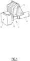
Figure 1 is a perspective view of a coupler and a weather protection cover, during assembly, according to an example of embodiment of the invention; -
Figure 2 is a perspective view of the weather protection cover ofFigure 1 ; -
Figure 3 is a schematic perspective view of a first part of the weather protection cover ofFigure 1 ; and -
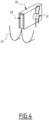
Figure 4 is a schematic perspective view of the connection of the first part ofFigure 3 with a second part of the weather protection cover ofFigure 1 .
-
-
Figure 1 shows aweather protection cover 10 intended to equip acoupler 12 of a car of a railway vehicle. Thecoupler 12 is intended to cooperate with another coupling element of another car of the railway vehicle. - The
coupler 12 comprises acoupler head 14 and acoupler body 16, in a classical manner known in itself. Thecoupler body 16 extends in a longitudinal direction. - In order to protect the
coupler 12 against weather, in particular snow and ice, thecoupler 12 is equipped with theweather protection cover 10 around thecoupler body 16, and with ahead cover 18 on thecoupler head 14. Thehead cover 18 is for example a metal sheet fixed in a detachable manner to thecoupler head 14, for example with screws. - Preferentially, the
head cover 18 comprises a flap that can be moved to let an access to thecoupler head 14 without needing removing thehead cover 18. - A shown in
figure 2 , theweather protection cover 10 is made in two parts, which are afirst cover part 20 and asecond cover part 22. - The
first cover part 20 has a U-shape in order to overlap thecoupler body 16. Thesecond cover part 22 has a generally plane shape in order to close theweather protection cover 10 into a general polyhedral shape. Thus, when thesecond cover part 22 is assembled with thefirst cover part 20, thecoupler body 16 is enclosed in theweather protection cover 10. - The
protection cover 10 extends in the longitudinal direction, with a cross section larger at a proximal end (i.e. the end near the carbody of the vehicle) than at a distal end (i.e the end near the coupler head 14). For example theprotection cover 10 has a truncated pyramid general shape or a truncated conical general shape. - In case of a truncated pyramid shape, at least the upper face of the pyramid is curved in order to facilitate the drainage of melting water. For instance, this upper face is curved from the center outward to the lateral sides.
- The
coupler body 16 classically has a variable length, for example, during coupling buff the reversible element in the coupler works. - Thus, the
weather protection cover 10 is preferentially made in a flexible material, in order to keep covering thecoupler body 16 even when its length changes. Preferentially, the material is water-repellent. - For example, the material is rubber, preferentially silicon based or Chlorosulfonated Polyethylene (CSM).
- Preferentially, the
weather protection cover 10 is corrugated. Thecover 10 forms abellow comprising folds 24 intended to move with respect to each other so that the length of the weather protection cover 10 changes with the length of thecoupler body 16. Thefolds 24 are perpendicular to the longitudinal direction. - The corrugations of the
cover 10 ensure its mobility. Thefolds 24 can move against each other. This ensures that snow/ice adhering for a short time is blown off again by the constant movements. Thecover 10 preferentially comprises between five and ten folds. - Each
fold 24 of thefirst part 20 is connected to each adjacent fold by aconnection line 26. Eachconnection line 26 is covered by a first reinforcingclamp 28. - The folds of the
second part 22 are also connected by similar connection lines covered by a second reinforcingclamp 30. - The
first clamps 28 of thefirst part 20 are arranged in the continuity of thesecond clamps 30 of thesecond part 22. - Preferentially, the
second clamps 30 overhang the connection lines of thesecond part 22, so eachsecond clamp 30 overlaps a respectivefirst clamp 28. Preferentially, a connection element, such as apin 32 or a screw, connects thesecond clamp 30 with the correspondingfirst clamps 28. - The
second clamps 30 allows the connection between thefirst part 20 and thesecond part 22. - Since the folds of the
first part 20 are connected to the folds of thesecond part 22, the first 20 and second 22 parts can extend together in length. - Preferentially, the
cover 10 is attached, at a distal end, to thecoupler head 14, and at a proximal end, to a bodywork part of the railway vehicle. Thus, the length of thecover 10 changes with moves of thecoupler head 14. - In case the
cover 10 has a truncated pyramidal shape or a truncated conical shape, the larger base is preferentially at the proximal end. - It appears that the
cover 10 allows protecting thecoupler body 16 from environmental influences, especially from snow and ice, so that the coupler's freedom of movement is not restricted. There is no obstruction to the movement of the coupler due to snow and ice accumulation on the coupler or in the coupling jaw or due to icing of the cover. Besides, the cover in two parts is easy to assembly.
Claims (8)
- A weather protection cover (10) for a coupler (12) of a railway vehicle, intended to be arranged around a coupler body (16) of the coupler (12), characterized in that the protection cover (10) comprises a first cover part (20) having a U-shape intended to be arranged around the coupler body (16), and a second cover part (22) intended to be assembled with the first cover part (20) in a detachable manner to finalize covering of the coupler body (16).
- The weather protection cover (10) according to claim 1, made in a flexible material, such as rubber, preferentially silicon based or Chlorosulfonated Polyethylene.
- The weather protection cover (10) according to claim 1 or 2, wherein the protection cover (10) has a cross section larger at a proximal end than at a distal end, for example the protection cover (10) has a truncated pyramid general shape or a truncated conical general shape.
- The weather protection cover (10) according to any of preceding claims, having an upper face that is curved, for example curved from the center outward to lateral sides.
- The weather protection cover (10) according to any of preceding claims, having a corrugated shape comprising folds (24).
- The weather protection cover (10) according to claim 5, wherein each fold (24) of the first cover part (20) is connected to each adjacent fold by a connection line (26), each connection line (26) being covered by a first reinforcing clamp (28), and the folds of the second cover part (22) are also connected by similar connection lines covered by a second reinforcing clamp (30).
- The weather protection cover (10) according to claim 6, wherein the second clamps (30) overhang the connection lines of the second cover part (22), so each second clamp (30) overlaps a respective first clamp (28).
- The weather protection cover (10) according to claim 7, wherein connection element, such as a pin (32) or a screw, connects each second clamp (30) with the corresponding first clamps (28).
Priority Applications (1)
| Application Number | Priority Date | Filing Date | Title |
|---|---|---|---|
| EP23307123.2A EP4566910A1 (en) | 2023-12-04 | 2023-12-04 | Weather protection cover for a coupler of a railway vehicle |
Applications Claiming Priority (1)
| Application Number | Priority Date | Filing Date | Title |
|---|---|---|---|
| EP23307123.2A EP4566910A1 (en) | 2023-12-04 | 2023-12-04 | Weather protection cover for a coupler of a railway vehicle |
Publications (1)
| Publication Number | Publication Date |
|---|---|
| EP4566910A1 true EP4566910A1 (en) | 2025-06-11 |
Family
ID=89222171
Family Applications (1)
| Application Number | Title | Priority Date | Filing Date |
|---|---|---|---|
| EP23307123.2A Pending EP4566910A1 (en) | 2023-12-04 | 2023-12-04 | Weather protection cover for a coupler of a railway vehicle |
Country Status (1)
| Country | Link |
|---|---|
| EP (1) | EP4566910A1 (en) |
Citations (5)
| Publication number | Priority date | Publication date | Assignee | Title |
|---|---|---|---|---|
| JP2942218B2 (en) * | 1997-06-30 | 1999-08-30 | 川崎重工業株式会社 | Coupling cover of high-speed leading vehicle |
| EP2853421B1 (en) * | 2013-09-26 | 2016-11-23 | Hübner GmbH & Co. KG | Repair set for replacing a worn roof area of a bellows separated from the rest of the bellows |
| CN113442958A (en) * | 2021-07-22 | 2021-09-28 | 中车长春轨道客车股份有限公司 | Ice and snow preventing device for high-speed train reconnection end |
| CN113942529A (en) * | 2021-12-01 | 2022-01-18 | 青岛思锐科技有限公司 | Train end protection device |
| EP3793880B1 (en) * | 2018-05-18 | 2023-07-12 | Voith Patent GmbH | Coupling device having a covering device, and rail vehicle having such a coupling device |
-
2023
- 2023-12-04 EP EP23307123.2A patent/EP4566910A1/en active Pending
Patent Citations (5)
| Publication number | Priority date | Publication date | Assignee | Title |
|---|---|---|---|---|
| JP2942218B2 (en) * | 1997-06-30 | 1999-08-30 | 川崎重工業株式会社 | Coupling cover of high-speed leading vehicle |
| EP2853421B1 (en) * | 2013-09-26 | 2016-11-23 | Hübner GmbH & Co. KG | Repair set for replacing a worn roof area of a bellows separated from the rest of the bellows |
| EP3793880B1 (en) * | 2018-05-18 | 2023-07-12 | Voith Patent GmbH | Coupling device having a covering device, and rail vehicle having such a coupling device |
| CN113442958A (en) * | 2021-07-22 | 2021-09-28 | 中车长春轨道客车股份有限公司 | Ice and snow preventing device for high-speed train reconnection end |
| CN113942529A (en) * | 2021-12-01 | 2022-01-18 | 青岛思锐科技有限公司 | Train end protection device |
Similar Documents
| Publication | Publication Date | Title |
|---|---|---|
| US8070205B2 (en) | Harness assembly for a dual-mode tailgate | |
| US6859971B2 (en) | Windshield wiper assembly having a winter boot | |
| US7004534B2 (en) | Vehicle front-body structure | |
| US5671563A (en) | Vehicle control arm device | |
| KR101366891B1 (en) | Front spoiler for a motor vehicle | |
| US20100025962A1 (en) | Gangway bellows cover-style connecting device for articulated vehicles | |
| US6283530B1 (en) | Arrangement for movable parts on vehicles | |
| CN109789881A (en) | Rail vehicle head | |
| US20220204058A1 (en) | Controlled Roof Drainage via the Bellows | |
| KR20010063128A (en) | reinforcement member for reinforcing frame for a motor vehicle | |
| JPH02286464A (en) | Elastically deformable corrugated membrane with increasing depth for mutual passing between connected cars for railway or land road | |
| US7267058B2 (en) | Articulated truck | |
| US4241945A (en) | Motor vehicle bumper | |
| US4247128A (en) | Bellows connection between front and rear section of a jointed bus | |
| CA2117025C (en) | Non-metallic polymer longitudinal hood collar | |
| US20250108523A1 (en) | Wire-body fixing member, wire-body-extension fixing member, and wire-body fitting method | |
| JP3622494B2 (en) | Protection structure of the cementer | |
| WO2007055153A1 (en) | Roof header structure | |
| US8230791B2 (en) | Device for lateral covering of the spacing between two vehicles coupled to each other, particularly rail cars | |
| EP1378605A2 (en) | Railroad communication tie | |
| JPH11180233A (en) | Bumper mounting structure | |
| JPH0330219Y2 (en) | ||
| JP7828542B2 (en) | Rear body structure | |
| JP4034256B2 (en) | Protection structure for engine peripherals | |
| US20030029512A1 (en) | Hose arrangement for vehicles |
Legal Events
| Date | Code | Title | Description |
|---|---|---|---|
| PUAI | Public reference made under article 153(3) epc to a published international application that has entered the european phase |
Free format text: ORIGINAL CODE: 0009012 |
|
| STAA | Information on the status of an ep patent application or granted ep patent |
Free format text: STATUS: THE APPLICATION HAS BEEN PUBLISHED |
|
| AK | Designated contracting states |
Kind code of ref document: A1 Designated state(s): AL AT BE BG CH CY CZ DE DK EE ES FI FR GB GR HR HU IE IS IT LI LT LU LV MC ME MK MT NL NO PL PT RO RS SE SI SK SM TR |
|
| STAA | Information on the status of an ep patent application or granted ep patent |
Free format text: STATUS: REQUEST FOR EXAMINATION WAS MADE |
|
| 17P | Request for examination filed |
Effective date: 20251210 |