EP4566891A1 - Multi-position low profile snap on mount assembly - Google Patents
Multi-position low profile snap on mount assembly Download PDFInfo
- Publication number
- EP4566891A1 EP4566891A1 EP24216247.7A EP24216247A EP4566891A1 EP 4566891 A1 EP4566891 A1 EP 4566891A1 EP 24216247 A EP24216247 A EP 24216247A EP 4566891 A1 EP4566891 A1 EP 4566891A1
- Authority
- EP
- European Patent Office
- Prior art keywords
- cable
- mount assembly
- base
- receiving
- latch
- Prior art date
- Legal status (The legal status is an assumption and is not a legal conclusion. Google has not performed a legal analysis and makes no representation as to the accuracy of the status listed.)
- Pending
Links
Images







Classifications
-
- B—PERFORMING OPERATIONS; TRANSPORTING
- B60—VEHICLES IN GENERAL
- B60R—VEHICLES, VEHICLE FITTINGS, OR VEHICLE PARTS, NOT OTHERWISE PROVIDED FOR
- B60R16/00—Electric or fluid circuits specially adapted for vehicles and not otherwise provided for; Arrangement of elements of electric or fluid circuits specially adapted for vehicles and not otherwise provided for
- B60R16/02—Electric or fluid circuits specially adapted for vehicles and not otherwise provided for; Arrangement of elements of electric or fluid circuits specially adapted for vehicles and not otherwise provided for electric constitutive elements
- B60R16/0207—Wire harnesses
- B60R16/0215—Protecting, fastening and routing means therefor
-
- F—MECHANICAL ENGINEERING; LIGHTING; HEATING; WEAPONS; BLASTING
- F16—ENGINEERING ELEMENTS AND UNITS; GENERAL MEASURES FOR PRODUCING AND MAINTAINING EFFECTIVE FUNCTIONING OF MACHINES OR INSTALLATIONS; THERMAL INSULATION IN GENERAL
- F16B—DEVICES FOR FASTENING OR SECURING CONSTRUCTIONAL ELEMENTS OR MACHINE PARTS TOGETHER, e.g. NAILS, BOLTS, CIRCLIPS, CLAMPS, CLIPS OR WEDGES; JOINTS OR JOINTING
- F16B5/00—Joining sheets or plates, e.g. panels, to one another or to strips or bars parallel to them
- F16B5/06—Joining sheets or plates, e.g. panels, to one another or to strips or bars parallel to them by means of clamps or clips
- F16B5/0685—Joining sheets or plates to strips or bars
-
- H—ELECTRICITY
- H02—GENERATION; CONVERSION OR DISTRIBUTION OF ELECTRIC POWER
- H02G—INSTALLATION OF ELECTRIC CABLES OR LINES, OR OF COMBINED OPTICAL AND ELECTRIC CABLES OR LINES
- H02G3/00—Installations of electric cables or lines or protective tubing therefor in or on buildings, equivalent structures or vehicles
- H02G3/02—Details
-
- H—ELECTRICITY
- H02—GENERATION; CONVERSION OR DISTRIBUTION OF ELECTRIC POWER
- H02G—INSTALLATION OF ELECTRIC CABLES OR LINES, OR OF COMBINED OPTICAL AND ELECTRIC CABLES OR LINES
- H02G3/00—Installations of electric cables or lines or protective tubing therefor in or on buildings, equivalent structures or vehicles
- H02G3/30—Installations of cables or lines on walls, floors or ceilings
-
- H—ELECTRICITY
- H02—GENERATION; CONVERSION OR DISTRIBUTION OF ELECTRIC POWER
- H02G—INSTALLATION OF ELECTRIC CABLES OR LINES, OR OF COMBINED OPTICAL AND ELECTRIC CABLES OR LINES
- H02G3/00—Installations of electric cables or lines or protective tubing therefor in or on buildings, equivalent structures or vehicles
- H02G3/30—Installations of cables or lines on walls, floors or ceilings
- H02G3/32—Installations of cables or lines on walls, floors or ceilings using mounting clamps
-
- B—PERFORMING OPERATIONS; TRANSPORTING
- B60—VEHICLES IN GENERAL
- B60Y—INDEXING SCHEME RELATING TO ASPECTS CROSS-CUTTING VEHICLE TECHNOLOGY
- B60Y2410/00—Constructional features of vehicle sub-units
- B60Y2410/115—Electric wiring; Electric connectors
-
- F—MECHANICAL ENGINEERING; LIGHTING; HEATING; WEAPONS; BLASTING
- F16—ENGINEERING ELEMENTS AND UNITS; GENERAL MEASURES FOR PRODUCING AND MAINTAINING EFFECTIVE FUNCTIONING OF MACHINES OR INSTALLATIONS; THERMAL INSULATION IN GENERAL
- F16B—DEVICES FOR FASTENING OR SECURING CONSTRUCTIONAL ELEMENTS OR MACHINE PARTS TOGETHER, e.g. NAILS, BOLTS, CIRCLIPS, CLAMPS, CLIPS OR WEDGES; JOINTS OR JOINTING
- F16B21/00—Means for preventing relative axial movement of a pin, spigot, shaft or the like and a member surrounding it; Stud-and-socket releasable fastenings
- F16B21/06—Releasable fastening devices with snap-action
-
- F—MECHANICAL ENGINEERING; LIGHTING; HEATING; WEAPONS; BLASTING
- F16—ENGINEERING ELEMENTS AND UNITS; GENERAL MEASURES FOR PRODUCING AND MAINTAINING EFFECTIVE FUNCTIONING OF MACHINES OR INSTALLATIONS; THERMAL INSULATION IN GENERAL
- F16L—PIPES; JOINTS OR FITTINGS FOR PIPES; SUPPORTS FOR PIPES, CABLES OR PROTECTIVE TUBING; MEANS FOR THERMAL INSULATION IN GENERAL
- F16L3/00—Supports for pipes, cables or protective tubing, e.g. hangers, holders, clamps, cleats, clips, brackets
- F16L3/22—Supports for pipes, cables or protective tubing, e.g. hangers, holders, clamps, cleats, clips, brackets specially adapted for supporting a number of parallel pipes at intervals
- F16L3/223—Supports for pipes, cables or protective tubing, e.g. hangers, holders, clamps, cleats, clips, brackets specially adapted for supporting a number of parallel pipes at intervals each support having one transverse base for supporting the pipes
- F16L3/2235—Supports for pipes, cables or protective tubing, e.g. hangers, holders, clamps, cleats, clips, brackets specially adapted for supporting a number of parallel pipes at intervals each support having one transverse base for supporting the pipes each pipe being supported by a common element fastened to the base
-
- H—ELECTRICITY
- H02—GENERATION; CONVERSION OR DISTRIBUTION OF ELECTRIC POWER
- H02G—INSTALLATION OF ELECTRIC CABLES OR LINES, OR OF COMBINED OPTICAL AND ELECTRIC CABLES OR LINES
- H02G3/00—Installations of electric cables or lines or protective tubing therefor in or on buildings, equivalent structures or vehicles
- H02G3/26—Installations of cables, lines, or separate protective tubing therefor directly on or in walls, ceilings, or floors
- H02G3/263—Installation, e.g. suspension, of conduit channels or other supports
Definitions
- the present invention relates to a mount assembly, and more particularly to a multi-position low profile snap on mount assembly.
- the present invention is directed to a multi-position snap on mount assembly secured to a vehicle frame for routing cables.
- the snap on mount assembly includes a base and a mount component.
- the base has a securement flange and a mating flange with a latch window.
- the mount component is positioned on the base.
- the mount component has an attachment member and a cable receiving member.
- the attachment member has a latch arm with a latch extending therefrom. The latch engages the latch window of the mating flange to secure the mount component to the base to form the snap on mount assembly.
- FIG. 1 illustrates the multi-position low profile snap on mount 50 of the present invention.
- the snap on mount 50 includes a base 52 and a mount component 90 designed to accommodate up to three cables.
- FIG. 2 illustrates a perspective view of the base 52 of the snap on mount 50.
- the base 52 is formed from stamped steel; however, other materials and manufacturing methods could be used.
- the base 52 includes a securement flange 54, a 90 degree bend 58, and a mating flange 60 that is perpendicular to the securement flange 54.
- the securement flange 54 includes a mounting hole 56.
- the mounting hole 56 receives a fastener 202 to secure the base 52 to a vehicle frame 200 (see FIGS. 7 -10 ).
- the mating flange 60 includes a top 62, a front 66, a back 68, and sides 70.
- the top 62 includes tapered corners 64 and the sides 70 include recessed mating cutouts 72 that define an upper portion 74 of the mating flange 60.
- the mating cutouts 72 include a horizontal indentation that leads to a vertical side extending to the tapered corner 64.
- the mating flange 60 also includes a latch window 76 centered in the mating flange 60.
- the latch window 76 is rectangular with a top 78, a bottom 80, and sides 82.
- FIG. 3 illustrates the mount component 90 of the snap on mount 50.
- the mount component 90 is injection molded with a robust polymer.
- the mount component 90 includes an attachment member 92 and a cable receiving member 120.
- the attachment member 92 includes legs 94 with a top 96, a bottom 98, a front 100, a back 102, and sides 104.
- the attachment member 92 includes a latch arm 106 with a latch 108 extending between each leg 94.
- the latch 108 is a projection that extends toward the center of the attachment member 92.
- the latch arm 106 extends longer than the legs 94 to facilitate engagement with the latch window 76 in the mating flange 60 of the base 52.
- the attachment member 92 also includes a mating cavity 110.
- the mating cavity 110 is defined by the top 96, bottom 98, front 100, back 102 and sides 104 of the legs 94. As described below, the mating cavity 110 receives the mating flange 60 of the base 52
- the cable receiving member 120 includes cable receiving lobes 122, cable spacer arms 124, and a lobe stem 126.
- the lobe stem 126 is a vertical member that provides support for the cable spacer arms 124.
- the cable spacer arms 124 extend from the lobe stem 126 and include curved outer ends.
- the lobe stem 126 spaces the cable spacer arms 124 to create the cable receiving lobes 122.
- the cable spacer arms 124 define three concave cable receiving lobes 122 for receiving a cable.
- the cable receiving member 120 also includes a centered cable tie pass thru slot 128 for receiving a cable tie 210 to secure the cables 220 positioned on the cable receiving lobes 122.
- FIG. 5 illustrates a cross sectional view of the snap on mount 50.
- the mount component 90 is secured to the base 52 by positioning the upper portion 74 of the mating flange 60 within the mating cavity 110.
- the latch 108 extending from the latch arm 106 engages the top 78 of the latch window 76 to secure the mount component 90 to the base 52.
- the bottoms of the legs rest on the horizontal indention of the recessed mating cutouts 72.
- FIG. 6 is a rear view of the snap on mount 50 with the latch arm 106 blocking the latch window 76 of the base 52.
- FIGS. 7-10 illustrate the multi-position low profile snap on mount 50 as it is installed on a vehicle frame 200.
- the base 52 is mounted to the structural frame 200 of a vehicle via a fastener 202.
- the mount component 90 is then placed over the base 52.
- the tapered corners 64 of the base 52 help guide the base 52 into the mating cavity 110 of the mount component 90.
- the upper portion 74 of the base 52 is positioned in the mating cavity 110 with the horizontal indentation and vertical side of the recessed mating cutouts 72 engaging the mating cavity 110.
- the latch arm 106 remains adjacent to the latch window 76 while the latch 108 engages the top 78 of the latch window 76 to secure the mount component 90 to the base 52.
- FIG. 10 illustrates a plurality of snap on mounts 50 secured to the structural frame 200 of the vehicle. The snap on mounts 50 are aligned along the vehicle frame 200 to facilitate routing of the power cabling in the vehicle.
- FIGS. 11-14 illustrate a second embodiment of the multi-position low profile snap on mount assembly.
- the multi-position low profile snap on mount assembly 250 includes a base 52 identical to the base described above and a mount component 290 designed to accommodate up to five cables.
- the mount component 290 includes an attachment member 292 and a cable receiving member 320.
- the attachment member 292 includes legs 294 with a top 296, a bottom 298, a front 300, a back 302, and sides 304.
- the attachment member 292 includes a latch arm 306 with a latch 308 extending between each leg 294. The latch arm 306 extends longer than the legs 294 to facilitate engagement with the latch window 76 in the mating flange 60 of the base 52.
- the cable receiving member 320 includes and open center 321, cable receiving lobes 322 and cable spacer arms 324 with range taking cavities 326.
- the cable spacer arms 324 are arranged to define five semicircular cable receiving lobes 322.
- the mount assembly 250 also includes a centered cable tie pass thru slot 328 for receiving a cable tie 210 to secure the cables 220 positioned on the cable receiving lobes 322.
- the attachment member 292 also includes a mating cavity 310.
- the mating cavity 310 is defined by the front 300, back 302 and sides 304 of the legs 294.
- the attachment member 292 is secured to the base 52 the same as described above with respect to mount component 90.
- the upper portion 74 of the mating flange 60 of the base 52 is positioned within the mating cavity 310 of the mount component 290.
- the latch 308 extending from the latch arm 306 engages the top 78 of the latch window 76 to secure the mount component 290 to the base 52.
- cables are placed in the cable receiving lobes 322 of snap on mount 250 to keep the cables separated.
- a cable tie is thread thru the cable tie pass thru slot, the cable tie is threaded, tensioned, and the tail is removed.
- the centers of the cable receiving lobes 322 are offset from the circumference of the cable receiving member 320 of the snap on mount 250 which allows cables to be easily snapped into place in the snap in mount 250 during installment. This allows for easier assembly as the installer's hands are allowed to be free to install the cable tie since the cables are secured in the cable receiving lobes 322.
- Range taking cavities 326 are located at the distal ends of the cable spacer arms 324 to allow the mounts to receive a range of cable sizes. If an installer decides to put smaller cables into the cable receiving lobes 322 of the snap on mount 250, the range taking cavities 326 allow the cable tie to be tightened down to different circumferences thereby keeping the smaller cables in place.
- FIG. 14 illustrates a plurality of snap on mounts 250 secured to the structural frame 200 of the vehicle.
- the snap on mounts 250 are aligned along the vehicle frame 200 to facilitate routing of the power cabling in the vehicle.
- the snap on mounts of the present invention have a low profile, they are light weight, and they require minimal space along the vehicle frame.
- the snap on mounts are easy to install and are easy to remove when maintenance is required.
- the cable spacer arms of the snap on mounts provide ample spacing for adjacent cables thereby eliminating accidental cable contacts.
- the structural frame can be designed with tapered corners, recessed cutouts, and latch window to directly receive the mount components. This enables the end user to only use a mount component thereby reducing weight, cost, and simplifying the install of the snap on mount.
Landscapes
- Engineering & Computer Science (AREA)
- Mechanical Engineering (AREA)
- Architecture (AREA)
- Civil Engineering (AREA)
- Structural Engineering (AREA)
- General Engineering & Computer Science (AREA)
- Installation Of Indoor Wiring (AREA)
- Supports For Pipes And Cables (AREA)
- Snaps, Bayonet Connections, Set Pins, And Snap Rings (AREA)
- Connections By Means Of Piercing Elements, Nuts, Or Screws (AREA)
Abstract
A mount assembly designed to secure cables to a vehicle frame. The mount assembly includes a base and a mount component based on the base. The base has a securement flange and a mating flange with a latch window. The mount component has an attachment member and a cable receiving member. The attachment member has a latch arm with a latch extending therefrom. The latch engages the latch window of the mating flange to secure the mount component to the base.
Description
- The present invention relates to a mount assembly, and more particularly to a multi-position low profile snap on mount assembly.
- The transition from fossil fuel powered vehicles to electric powered vehicles continues to accelerate. Electric powered passenger vehicles have been leading the transition; however, now heavy duty trucks are making the conversion to be electric powered. As in any vehicle design, space and weight are top concerns when designing the vehicle or truck. Passenger vehicles are normally 4000 to 6000 pounds, while a fully loaded tractor trailer or heavy duty truck can weigh up to 80,000 pounds. Thus, more energy is required to power the heavy duty truck and the load in tow. The cables used to transport the electric currents are typically larger in heavy duty trucks and the batteries are further from the motors when compared to passenger vehicles. As a result, the electric vehicle manufacturers of heavy duty trucks and passenger vehicles desire a space and weight saving method for routing the power cables in the vehicles. There is a desire for the cable routing method to be low cost, easy to install and easy to remove for maintenance or repairs. There is also a desire for the cable routing method to withstand harsh environments and vibration associated with the truck or vehicle's outdoor road use.
- The present invention is directed to a multi-position snap on mount assembly secured to a vehicle frame for routing cables. The snap on mount assembly includes a base and a mount component. The base has a securement flange and a mating flange with a latch window. The mount component is positioned on the base. The mount component has an attachment member and a cable receiving member. The attachment member has a latch arm with a latch extending therefrom. The latch engages the latch window of the mating flange to secure the mount component to the base to form the snap on mount assembly.
-
-
FIG. 1 is a front perspective view of the multi-position low profile snap on mount assembly of the present invention. -
FIG. 2 is a perspective view of the base of the multi-position low profile snap on mount assembly ofFIG. 1 . -
FIG. 3 is a perspective view of the mount component of the multi-position low profile snap on mount assembly ofFIG. 1 . -
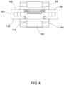
FIG. 4 is a bottom view of the mount component ofFIG. 3 . -
FIG. 5 is a cross sectional view of the multi-position low profile snap on mount assembly ofFIG. 1 taken along line 5-5. -
FIG. 6 is a back view of the multi-position low profile snap on mount assembly ofFIG. 1 . -
FIG. 7 is a perspective view of the base ofFIG. 2 secured to a vehicle frame. -
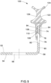
FIG. 8 is a perspective view of the multi-position low profile snap on mount assembly ofFIG. 1 secured to a vehicle frame. -
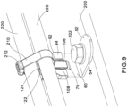
FIG. 9 is a perspective view of the multi-position low profile snap on mount assembly ofFIG. 8 with cables secured to the mount assembly. -
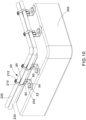
FIG. 10 is a perspective view of a plurality of the multi-position low profile snap on mount assemblies ofFIG. 1 secured to a vehicle frame with cables secured to the mount assembly. -
FIG. 11 is a front perspective view of a second embodiment of the multi-position low profile snap on mount assembly of the present invention. -
FIG. 12 is a perspective view of the mount component of the multi-position low profile snap on mount assembly ofFIG. 11 . -
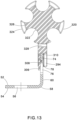
FIG. 13 is a cross sectional view of the multi-position low profile snap on mount assembly ofFIG. 11 taken along line 13-13. -
FIG. 14 is a perspective view of a plurality of the multi-position low profile snap on mount assemblies ofFIG. 11 secured to a vehicle frame with cables secured to the mount assembly. -
FIG. 1 illustrates the multi-position low profile snap onmount 50 of the present invention. The snap onmount 50 includes abase 52 and amount component 90 designed to accommodate up to three cables. -
FIG. 2 illustrates a perspective view of thebase 52 of the snap onmount 50. Thebase 52 is formed from stamped steel; however, other materials and manufacturing methods could be used. Thebase 52 includes asecurement flange 54, a 90degree bend 58, and amating flange 60 that is perpendicular to thesecurement flange 54. Thesecurement flange 54 includes amounting hole 56. Themounting hole 56 receives afastener 202 to secure thebase 52 to a vehicle frame 200 (seeFIGS. 7 -10 ). Themating flange 60 includes atop 62, afront 66, aback 68, andsides 70. Thetop 62 includestapered corners 64 and thesides 70 includerecessed mating cutouts 72 that define anupper portion 74 of themating flange 60. Themating cutouts 72 include a horizontal indentation that leads to a vertical side extending to thetapered corner 64. Themating flange 60 also includes alatch window 76 centered in themating flange 60. Thelatch window 76 is rectangular with atop 78, abottom 80, andsides 82. -
FIG. 3 illustrates themount component 90 of the snap onmount 50. Themount component 90 is injection molded with a robust polymer. Themount component 90 includes anattachment member 92 and acable receiving member 120. Theattachment member 92 includeslegs 94 with atop 96, abottom 98, afront 100, aback 102, andsides 104. Theattachment member 92 includes alatch arm 106 with alatch 108 extending between eachleg 94. Thelatch 108 is a projection that extends toward the center of theattachment member 92. Thelatch arm 106 extends longer than thelegs 94 to facilitate engagement with thelatch window 76 in themating flange 60 of thebase 52. As illustrated inFIG. 4 , theattachment member 92 also includes amating cavity 110. Themating cavity 110 is defined by thetop 96,bottom 98,front 100,back 102 andsides 104 of thelegs 94. As described below, themating cavity 110 receives themating flange 60 of thebase 52 to form the snap on mount assembly. - The
cable receiving member 120 includescable receiving lobes 122,cable spacer arms 124, and alobe stem 126. Thelobe stem 126 is a vertical member that provides support for thecable spacer arms 124. Thecable spacer arms 124 extend from thelobe stem 126 and include curved outer ends. The lobe stem 126 spaces thecable spacer arms 124 to create thecable receiving lobes 122. As illustrated inFIG. 1 , thecable spacer arms 124 define three concavecable receiving lobes 122 for receiving a cable. Thecable receiving member 120 also includes a centered cable tie pass thruslot 128 for receiving acable tie 210 to secure thecables 220 positioned on thecable receiving lobes 122. -
FIG. 5 illustrates a cross sectional view of the snap onmount 50. Themount component 90 is secured to thebase 52 by positioning theupper portion 74 of themating flange 60 within themating cavity 110. Thelatch 108 extending from thelatch arm 106 engages the top 78 of thelatch window 76 to secure themount component 90 to thebase 52. The bottoms of the legs rest on the horizontal indention of the recessedmating cutouts 72.FIG. 6 is a rear view of the snap onmount 50 with thelatch arm 106 blocking thelatch window 76 of thebase 52. -
FIGS. 7-10 illustrate the multi-position low profile snap onmount 50 as it is installed on avehicle frame 200. Thebase 52 is mounted to thestructural frame 200 of a vehicle via afastener 202. Themount component 90 is then placed over thebase 52. The taperedcorners 64 of the base 52 help guide the base 52 into themating cavity 110 of themount component 90. Theupper portion 74 of thebase 52 is positioned in themating cavity 110 with the horizontal indentation and vertical side of the recessedmating cutouts 72 engaging themating cavity 110. Thelatch arm 106 remains adjacent to thelatch window 76 while thelatch 108 engages the top 78 of thelatch window 76 to secure themount component 90 to thebase 52.Cables 220 are then placed in thecable receiving lobes 122 for routing. Acable tie 210 is threaded through the cable tie pass throughslot 128 and wrapped around thecables 220. Thecable tie 210 is threaded through thecable tie head 212 and tensioned around thecables 220. Once tensioned, the cable tie tail is removed (not illustrated).FIG. 10 illustrates a plurality of snap onmounts 50 secured to thestructural frame 200 of the vehicle. The snap onmounts 50 are aligned along thevehicle frame 200 to facilitate routing of the power cabling in the vehicle. -
FIGS. 11-14 illustrate a second embodiment of the multi-position low profile snap on mount assembly. The multi-position low profile snap onmount assembly 250 includes a base 52 identical to the base described above and amount component 290 designed to accommodate up to five cables. As illustrated inFIGS. 11 and12 , themount component 290 includes anattachment member 292 and acable receiving member 320. Theattachment member 292 includeslegs 294 with a top 296, a bottom 298, a front 300, a back 302, and sides 304. Theattachment member 292 includes alatch arm 306 with alatch 308 extending between eachleg 294. Thelatch arm 306 extends longer than thelegs 294 to facilitate engagement with thelatch window 76 in themating flange 60 of thebase 52. - The
cable receiving member 320 includes andopen center 321,cable receiving lobes 322 andcable spacer arms 324 withrange taking cavities 326. Thecable spacer arms 324 are arranged to define five semicircularcable receiving lobes 322. - The
mount assembly 250 also includes a centered cable tie pass thruslot 328 for receiving acable tie 210 to secure thecables 220 positioned on thecable receiving lobes 322. - As illustrated in
FIG. 13 , theattachment member 292 also includes amating cavity 310. Themating cavity 310 is defined by the front 300, back 302 andsides 304 of thelegs 294. Theattachment member 292 is secured to the base 52 the same as described above with respect to mountcomponent 90. Theupper portion 74 of themating flange 60 of thebase 52 is positioned within themating cavity 310 of themount component 290. Thelatch 308 extending from thelatch arm 306 engages the top 78 of thelatch window 76 to secure themount component 290 to thebase 52. - As described above with respect to the snap on
mount 50, cables are placed in thecable receiving lobes 322 of snap onmount 250 to keep the cables separated. A cable tie is thread thru the cable tie pass thru slot, the cable tie is threaded, tensioned, and the tail is removed. The centers of thecable receiving lobes 322 are offset from the circumference of thecable receiving member 320 of the snap onmount 250 which allows cables to be easily snapped into place in the snap inmount 250 during installment. This allows for easier assembly as the installer's hands are allowed to be free to install the cable tie since the cables are secured in thecable receiving lobes 322. Range takingcavities 326 are located at the distal ends of thecable spacer arms 324 to allow the mounts to receive a range of cable sizes. If an installer decides to put smaller cables into thecable receiving lobes 322 of the snap onmount 250, therange taking cavities 326 allow the cable tie to be tightened down to different circumferences thereby keeping the smaller cables in place. -
FIG. 14 illustrates a plurality of snap onmounts 250 secured to thestructural frame 200 of the vehicle. The snap onmounts 250 are aligned along thevehicle frame 200 to facilitate routing of the power cabling in the vehicle. - The snap on mounts of the present invention have a low profile, they are light weight, and they require minimal space along the vehicle frame. The snap on mounts are easy to install and are easy to remove when maintenance is required. The cable spacer arms of the snap on mounts provide ample spacing for adjacent cables thereby eliminating accidental cable contacts. Additionally, if desired, the structural frame can be designed with tapered corners, recessed cutouts, and latch window to directly receive the mount components. This enables the end user to only use a mount component thereby reducing weight, cost, and simplifying the install of the snap on mount.
- Furthermore, while the particular preferred embodiments of the present invention have been shown and described, it will be obvious to those skilled in the art that changes and modifications may be made without departing from the teaching of the invention. The matter set forth in the foregoing description and accompanying drawings is offered by way of illustration only and not as limitation. The actual scope of the invention is intended to be defined in the following claims when viewed in their proper perspective.
- Examples of the present disclosure are set out in the following numbered clauses:
- 1. A mount assembly for securing cables to a vehicle frame, the mount assembly comprising:
- a base having a securement flange and a mating flange with a latch window; and
- a mount component positioned on the base, the mount component having an attachment member and a cable receiving member, wherein the attachment member has a latch arm with a latch extending therefrom;
- whereby the latch extending from the latch arm of the attachment member engages the latch window of the mating flange to secure the mount component to the base.
- 2. The mount assembly of clause 1, wherein the securement flange of the base has a mounting hole for receiving a fastener to secure the base to the vehicle frame.
- 3. The mount assembly of clause 1, wherein the mating flange of the base is perpendicular to the securement flange of the base.
- 4. The mount assembly of clause 1, wherein the latch window is rectangular with a top, a bottom, and sides.
- 5. The mount assembly of clause 1, wherein the mating flange includes a top, a front, a back, and sides, the top of the mating flange has tapered corners and the sides of the mating flange have mating cutouts.
- 6. The mount assembly of clause 1, wherein the attachment member includes a leg positioned on each side of the latch arm; the legs have a top, a bottom, a front, a back, and sides.
- 7. The mount assembly of clause 6, wherein the attachment member further comprises a mating cavity defined by the front, back and sides of the legs; wherein the mating cavity receives the mating flange of the base.
- 8. The mount assembly of clause 1, wherein the cable receiving member further comprises a lobe stem with cable spacer arms that define concave cable receiving lobes for receiving cables.
- 9. The mount assembly of clause 8, wherein the cable receiving member has a centered cable tie pass thru slot for receiving a cable tie to secure the cables positioned in the cable receiving lobes.
- 10. The mount assembly of clause 1, wherein the cable receiving member further comprises cable spacer arms arranged to define semicircular cable receiving lobes for receiving a cable.
- 11. The mount assembly of clause 10, wherein the cable spacer arms include range taking cavities located at the distal ends of the cable spacer arms to allow the mount assembly to receive a range of cable sizes.
- 12. The mount assembly of clause 10, further comprising a centered cable tie pass thru slot for receiving a cable tie to secure the cables positioned in the semicircular cable receiving lobes.
- 13. A mount assembly for securing cables to a vehicle frame, the mount assembly comprising:
- a base having a securement flange and a mating flange with a latch window, the mating flange includes a top, a front, a back, and sides, the top of the mating flange has tapered corners and the sides of the mating flange have mating cutouts; and
- a mount component positioned on the base, the mount component having an attachment member and a cable receiving member, wherein the attachment member has a latch arm with a latch extending therefrom, the attachment member includes legs positioned on each side of the latch arm; the legs have a top, a bottom, a front, a back, and sides defining a mating cavity in the attachment member;
- wherein the mating cavity receives the mating flange of the base and the latch engages the latch window of the mating flange to secure the mount component to the base.
- 14. The mount assembly of
clause 13, wherein the cable receiving member further comprises a lobe stem with cable spacer arms that define concave cable receiving lobes for receiving cables. - 15. The mount assembly of clause 14, wherein the cable receiving member has a centered cable tie pass thru slot for receiving a cable tie to secure the cables positioned in the cable receiving lobes.
- 16. The mount assembly of
clause 13, wherein the cable receiving member further comprises cable spacer arms arranged to define semicircular cable receiving lobes for receiving a cable. - 17. The mount assembly of clause 16, wherein the cable spacer arms include range taking cavities located at the distal ends of the cable spacer arms to allow the mount assembly to receive a range of cable sizes.
- 18. The mount assembly of clause 16, further comprising a centered cable tie pass thru slot for receiving a cable tie to secure the cables positioned in the semicircular cable receiving lobes.
Claims (13)
- A mount assembly for securing cables to a vehicle frame, the mount assembly comprising:a base having a securement flange and a mating flange with a latch window; anda mount component positioned on the base, the mount component having an attachment member and a cable receiving member, wherein the attachment member has a latch arm with a latch extending therefrom;whereby the latch extending from the latch arm of the attachment member engages the latch window of the mating flange to secure the mount component to the base.
- The mount assembly of claim 1, wherein the securement flange of the base has a mounting hole for receiving a fastener to secure the base to the vehicle frame.
- The mount assembly of claim 1 or 2, wherein the mating flange of the base is perpendicular to the securement flange of the base.
- The mount assembly of any preceding claim, wherein the latch window is rectangular with a top, a bottom, and sides.
- The mount assembly of any preceding claim, wherein the mating flange includes a top, a front, a back, and sides, the top of the mating flange has tapered corners and the sides of the mating flange have mating cutouts.
- The mount assembly of any preceding claim, wherein the attachment member includes a leg positioned on each side of the latch arm; the legs have a top, a bottom, a front, a back, and sides, optionally wherein the attachment member further comprises a mating cavity defined by the front, back and sides of the legs; wherein the mating cavity receives the mating flange of the base.
- The mount assembly of any preceding claim, wherein the cable receiving member further comprises a lobe stem with cable spacer arms that define concave cable receiving lobes for receiving cables, optionally wherein the cable receiving member has a centered cable tie pass thru slot for receiving a cable tie to secure the cables positioned in the cable receiving lobes.
- The mount assembly of any preceding claim, wherein the cable receiving member further comprises cable spacer arms arranged to define semicircular cable receiving lobes for receiving a cable, optionally wherein the cable spacer arms include range taking cavities located at the distal ends of the cable spacer arms to allow the mount assembly to receive a range of cable sizes.
- The mount assembly of any preceding claim, further comprising a centered cable tie pass thru slot for receiving a cable tie to secure the cables positioned in the semicircular cable receiving lobes.
- A mount assembly for securing cables to a vehicle frame, the mount assembly comprising:a base having a securement flange and a mating flange with a latch window, the mating flange includes a top, a front, a back, and sides, the top of the mating flange has tapered corners and the sides of the mating flange have mating cutouts; anda mount component positioned on the base, the mount component having an attachment member and a cable receiving member, wherein the attachment member has a latch arm with a latch extending therefrom, the attachment member includes legs positioned on each side of the latch arm; the legs have a top, a bottom, a front, a back, and sides defining a mating cavity in the attachment member;wherein the mating cavity receives the mating flange of the base and the latch engages the latch window of the mating flange to secure the mount component to the base.
- The mount assembly of claim 10, wherein the cable receiving member further comprises a lobe stem with cable spacer arms that define concave cable receiving lobes for receiving cables, optionally wherein the cable receiving member has a centered cable tie pass thru slot for receiving a cable tie to secure the cables positioned in the cable receiving lobes.
- The mount assembly of claim 10 or 11, wherein the cable receiving member further comprises cable spacer arms arranged to define semicircular cable receiving lobes for receiving a cable, optionally wherein the cable spacer arms include range taking cavities located at the distal ends of the cable spacer arms to allow the mount assembly to receive a range of cable sizes.
- The mount assembly of any of claims 10-12, further comprising a centered cable tie pass thru slot for receiving a cable tie to secure the cables positioned in the semicircular cable receiving lobes.
Applications Claiming Priority (1)
| Application Number | Priority Date | Filing Date | Title |
|---|---|---|---|
| US18/528,980 US12528427B2 (en) | 2023-12-05 | 2023-12-05 | Multi-position low profile snap on mount assembly |
Publications (1)
| Publication Number | Publication Date |
|---|---|
| EP4566891A1 true EP4566891A1 (en) | 2025-06-11 |
Family
ID=93741276
Family Applications (1)
| Application Number | Title | Priority Date | Filing Date |
|---|---|---|---|
| EP24216247.7A Pending EP4566891A1 (en) | 2023-12-05 | 2024-11-28 | Multi-position low profile snap on mount assembly |
Country Status (5)
| Country | Link |
|---|---|
| US (1) | US12528427B2 (en) |
| EP (1) | EP4566891A1 (en) |
| JP (1) | JP2025090551A (en) |
| KR (1) | KR20250085613A (en) |
| MX (1) | MX2024013831A (en) |
Citations (3)
| Publication number | Priority date | Publication date | Assignee | Title |
|---|---|---|---|---|
| US20130187012A1 (en) * | 2012-01-19 | 2013-07-25 | Airbus Operations Limited | Cable retainer |
| EP2795140B1 (en) * | 2011-12-22 | 2016-09-14 | Panduit Corp. | Cable tie mount |
| EP3296604A1 (en) * | 2016-09-15 | 2018-03-21 | Daiwa Kasei Industry Co., Ltd. | Bracket assembling mechanism |
Family Cites Families (36)
| Publication number | Priority date | Publication date | Assignee | Title |
|---|---|---|---|---|
| US3632069A (en) | 1970-02-11 | 1972-01-04 | Panduit Corp | Bracket for mounting cable bundles in lightening holes |
| US4518138A (en) * | 1981-04-08 | 1985-05-21 | Ford Motor Company | Fastening device |
| US4974798A (en) * | 1989-12-18 | 1990-12-04 | Chrysler Corporation | Vehicle wiring harness cable mounting assembly structure |
| US5168904A (en) | 1991-10-23 | 1992-12-08 | Electro-Wire Products, Inc. | Reconfigurable wiring harness jig |
| US5390876A (en) * | 1993-11-19 | 1995-02-21 | Sumitomo Denso Kabushiki Kaisha | Holder for fixing wiring harness and the like to automobile body |
| US5597980A (en) * | 1994-11-30 | 1997-01-28 | Yazaki Corporation | Detachable mounting mechanism for a fuel injector wiring harness cover |
| US5547152A (en) | 1994-12-09 | 1996-08-20 | Connection Systems Group | Pipe mounting bracket |
| JPH1113941A (en) * | 1997-06-19 | 1999-01-22 | Sumitomo Wiring Syst Ltd | Clamp for locking bracket |
| US6672029B2 (en) * | 2001-12-12 | 2004-01-06 | Woodrow James Tucker | Pipe support apparatus |
| US20030173470A1 (en) * | 2002-03-12 | 2003-09-18 | Geiger Gerard G. | Conduit Isolator Mount |
| US6685514B2 (en) * | 2002-04-05 | 2004-02-03 | Larry J. Costa | Folding blade electrical terminal |
| US20040076465A1 (en) | 2002-07-11 | 2004-04-22 | Hellermann Tyton Corporation | Stud weldable mount and method |
| US7290739B2 (en) * | 2004-03-08 | 2007-11-06 | Airbus Deutschland Gmbh | Clamp support |
| US6903275B1 (en) * | 2004-10-22 | 2005-06-07 | Yazaki North America, Inc. | Mounting device for a wire harness shield |
| US8020811B2 (en) * | 2005-07-07 | 2011-09-20 | Panduit Corp. | Cable bracket and strap assembly |
| DE202005015875U1 (en) | 2005-10-07 | 2007-02-15 | S-Fasteners Gmbh | Holder arrangement for cables or similar with adjustable turn-stop positions |
| US20070120023A1 (en) * | 2005-11-29 | 2007-05-31 | Cnh America Llc | Hydraulic hose retention device |
| JP4976708B2 (en) * | 2006-03-06 | 2012-07-18 | 住友電装株式会社 | Fitting |
| US7497718B2 (en) * | 2006-11-08 | 2009-03-03 | International Truck Intellectual Property Company, Llc | Routing clip elements with a living hinge and interlocking closure |
| DE102008061613A1 (en) | 2008-12-11 | 2010-07-01 | Trw Automotive Electronics & Components Gmbh | Device for fastening a vehicle interior trim |
| DE102010021835B4 (en) | 2010-05-28 | 2019-05-16 | Airbus Operations Gmbh | Cable holding device for bundle laying of cables, in particular coaxial cables, in an aircraft |
| GB201009963D0 (en) | 2010-06-15 | 2010-07-21 | Airbus Operations Ltd | Modular conduit retntion system |
| US9067717B2 (en) * | 2011-10-27 | 2015-06-30 | Panduit Corp. | Bundle spacing device |
| US9534708B2 (en) | 2012-09-04 | 2017-01-03 | II Louis Cripps | Multiple axis control suspension system and method |
| US9528535B2 (en) | 2013-03-11 | 2016-12-27 | Illinois Tool Works Inc. | Multifunctional adaptor |
| US20160121822A1 (en) | 2013-05-29 | 2016-05-05 | International Engine Intellectual Property Company ,LLC. | Harness clip and system for clipping wiring harness |
| US9653901B2 (en) * | 2014-10-22 | 2017-05-16 | Daiwa Kasei Industry Co., Ltd. | Holding component for vehicle |
| EP3015317B1 (en) * | 2014-10-30 | 2018-12-05 | Nexans | Assembly for the attachment of an elongated object in a motor vehicle |
| DE102014016726B3 (en) | 2014-11-13 | 2016-05-19 | Hellermann Tyton Ab | fastening device |
| US9920858B2 (en) | 2015-06-30 | 2018-03-20 | Cnh Industrial America Llc | Mounting device for tubular elements |
| KR102020162B1 (en) | 2015-08-25 | 2019-09-09 | 헬러만타이톤 코포레이션 | Blind hole mount |
| JP6561287B2 (en) * | 2015-11-30 | 2019-08-21 | 北川工業株式会社 | Noise countermeasure material |
| US10903632B2 (en) * | 2016-02-05 | 2021-01-26 | Hellermanntyton Corporation | Adjustable P-clamp with multiple mounting options |
| EP3336989B1 (en) | 2016-12-16 | 2020-07-22 | HellermannTyton GmbH | Cable fixation device |
| DE102019216046A1 (en) | 2019-10-17 | 2021-04-22 | Hellermanntyton Gmbh | Cable holder for fixing at least two cables together |
| US11991853B2 (en) * | 2022-06-29 | 2024-05-21 | Quanta Computer Inc. | Cable clip |
-
2023
- 2023-12-05 US US18/528,980 patent/US12528427B2/en active Active
-
2024
- 2024-11-08 MX MX2024013831A patent/MX2024013831A/en unknown
- 2024-11-26 KR KR1020240170652A patent/KR20250085613A/en active Pending
- 2024-11-28 EP EP24216247.7A patent/EP4566891A1/en active Pending
- 2024-12-04 JP JP2024211524A patent/JP2025090551A/en active Pending
Patent Citations (3)
| Publication number | Priority date | Publication date | Assignee | Title |
|---|---|---|---|---|
| EP2795140B1 (en) * | 2011-12-22 | 2016-09-14 | Panduit Corp. | Cable tie mount |
| US20130187012A1 (en) * | 2012-01-19 | 2013-07-25 | Airbus Operations Limited | Cable retainer |
| EP3296604A1 (en) * | 2016-09-15 | 2018-03-21 | Daiwa Kasei Industry Co., Ltd. | Bracket assembling mechanism |
Also Published As
| Publication number | Publication date |
|---|---|
| US12528427B2 (en) | 2026-01-20 |
| KR20250085613A (en) | 2025-06-12 |
| JP2025090551A (en) | 2025-06-17 |
| MX2024013831A (en) | 2025-07-01 |
| US20250178546A1 (en) | 2025-06-05 |
Similar Documents
| Publication | Publication Date | Title |
|---|---|---|
| CN113677556A (en) | Equipment, systems and vehicles for installing traction batteries | |
| US11165227B2 (en) | Power distribution unit, such as a fuse box for a vehicle | |
| CA1329254C (en) | Resilient electrical component housing bracket | |
| CN213026311U (en) | Power battery and vehicle | |
| US12528427B2 (en) | Multi-position low profile snap on mount assembly | |
| KR20140087422A (en) | Box for vehicle | |
| CN113039678B (en) | Cover for battery module, battery module device and battery | |
| CN215244304U (en) | Special bracket for diesel extended-range electric light truck battery pack | |
| KR102033722B1 (en) | Battery mounting assembly of commercial vehicle | |
| CN218577621U (en) | Storing box installation assembly and vehicle | |
| CN113363658B (en) | Storage battery tray mounting structure and vehicle | |
| KR100755031B1 (en) | Mounting structure of fuse box for battery | |
| CN212848618U (en) | Bracket fixing box of battery module | |
| CN116316348A (en) | Junction Boxes and Vehicles | |
| CN214189822U (en) | Integrated vehicle body structure and automobile | |
| CN223911758U (en) | A BMS mounting bracket and battery module | |
| CN222355858U (en) | Cable fixing device, electric equipment and vehicle | |
| CN217768644U (en) | Battery box for assembling vertical battery module | |
| CN223479221U (en) | Stop gear and contain its electric bicycle | |
| CN222905439U (en) | Luggage rack mounting assembly and vehicle | |
| CN223858329U (en) | Box structure and battery system | |
| CN221328003U (en) | Positive and negative poles and FPC's fixed bolster and battery package | |
| CN222845273U (en) | Tank body connecting assembly and vehicle with same | |
| CN223942321U (en) | Bridge rack | |
| US20240157892A1 (en) | Power conversion unit |
Legal Events
| Date | Code | Title | Description |
|---|---|---|---|
| PUAI | Public reference made under article 153(3) epc to a published international application that has entered the european phase |
Free format text: ORIGINAL CODE: 0009012 |
|
| STAA | Information on the status of an ep patent application or granted ep patent |
Free format text: STATUS: THE APPLICATION HAS BEEN PUBLISHED |
|
| AK | Designated contracting states |
Kind code of ref document: A1 Designated state(s): AL AT BE BG CH CY CZ DE DK EE ES FI FR GB GR HR HU IE IS IT LI LT LU LV MC ME MK MT NL NO PL PT RO RS SE SI SK SM TR |
|
| STAA | Information on the status of an ep patent application or granted ep patent |
Free format text: STATUS: REQUEST FOR EXAMINATION WAS MADE |
|
| 17P | Request for examination filed |
Effective date: 20251211 |