EP4566887A1 - Image capturing apparatus, movable apparatus, image capturing method, and storage medium - Google Patents
Image capturing apparatus, movable apparatus, image capturing method, and storage medium Download PDFInfo
- Publication number
- EP4566887A1 EP4566887A1 EP24214715.5A EP24214715A EP4566887A1 EP 4566887 A1 EP4566887 A1 EP 4566887A1 EP 24214715 A EP24214715 A EP 24214715A EP 4566887 A1 EP4566887 A1 EP 4566887A1
- Authority
- EP
- European Patent Office
- Prior art keywords
- image capturing
- video image
- image
- lateral direction
- region
- Prior art date
- Legal status (The legal status is an assumption and is not a legal conclusion. Google has not performed a legal analysis and makes no representation as to the accuracy of the status listed.)
- Withdrawn
Links
Images






Classifications
-
- H—ELECTRICITY
- H04—ELECTRIC COMMUNICATION TECHNIQUE
- H04N—PICTORIAL COMMUNICATION, e.g. TELEVISION
- H04N25/00—Circuitry of solid-state image sensors [SSIS]; Control thereof
- H04N25/70—SSIS architectures; Circuits associated therewith
- H04N25/702—SSIS architectures characterised by non-identical, non-equidistant or non-planar pixel layout
-
- B—PERFORMING OPERATIONS; TRANSPORTING
- B60—VEHICLES IN GENERAL
- B60R—VEHICLES, VEHICLE FITTINGS, OR VEHICLE PARTS, NOT OTHERWISE PROVIDED FOR
- B60R1/00—Optical viewing arrangements; Real-time viewing arrangements for drivers or passengers using optical image capturing systems, e.g. cameras or video systems specially adapted for use in or on vehicles
- B60R1/20—Real-time viewing arrangements for drivers or passengers using optical image capturing systems, e.g. cameras or video systems specially adapted for use in or on vehicles
- B60R1/22—Real-time viewing arrangements for drivers or passengers using optical image capturing systems, e.g. cameras or video systems specially adapted for use in or on vehicles for viewing an area outside the vehicle, e.g. the exterior of the vehicle
- B60R1/23—Real-time viewing arrangements for drivers or passengers using optical image capturing systems, e.g. cameras or video systems specially adapted for use in or on vehicles for viewing an area outside the vehicle, e.g. the exterior of the vehicle with a predetermined field of view
- B60R1/27—Real-time viewing arrangements for drivers or passengers using optical image capturing systems, e.g. cameras or video systems specially adapted for use in or on vehicles for viewing an area outside the vehicle, e.g. the exterior of the vehicle with a predetermined field of view providing all-round vision, e.g. using omnidirectional cameras
-
- B—PERFORMING OPERATIONS; TRANSPORTING
- B60—VEHICLES IN GENERAL
- B60R—VEHICLES, VEHICLE FITTINGS, OR VEHICLE PARTS, NOT OTHERWISE PROVIDED FOR
- B60R1/00—Optical viewing arrangements; Real-time viewing arrangements for drivers or passengers using optical image capturing systems, e.g. cameras or video systems specially adapted for use in or on vehicles
- B60R1/20—Real-time viewing arrangements for drivers or passengers using optical image capturing systems, e.g. cameras or video systems specially adapted for use in or on vehicles
-
- B—PERFORMING OPERATIONS; TRANSPORTING
- B60—VEHICLES IN GENERAL
- B60R—VEHICLES, VEHICLE FITTINGS, OR VEHICLE PARTS, NOT OTHERWISE PROVIDED FOR
- B60R1/00—Optical viewing arrangements; Real-time viewing arrangements for drivers or passengers using optical image capturing systems, e.g. cameras or video systems specially adapted for use in or on vehicles
- B60R1/20—Real-time viewing arrangements for drivers or passengers using optical image capturing systems, e.g. cameras or video systems specially adapted for use in or on vehicles
- B60R1/31—Real-time viewing arrangements for drivers or passengers using optical image capturing systems, e.g. cameras or video systems specially adapted for use in or on vehicles providing stereoscopic vision
-
- G—PHYSICS
- G02—OPTICS
- G02B—OPTICAL ELEMENTS, SYSTEMS OR APPARATUS
- G02B13/00—Optical objectives specially designed for the purposes specified below
- G02B13/06—Panoramic objectives; So-called "sky lenses" including panoramic objectives having reflecting surfaces
-
- G—PHYSICS
- G02—OPTICS
- G02B—OPTICAL ELEMENTS, SYSTEMS OR APPARATUS
- G02B3/00—Simple or compound lenses
- G02B3/02—Simple or compound lenses with non-spherical faces
- G02B3/04—Simple or compound lenses with non-spherical faces with continuous faces that are rotationally symmetrical but deviate from a true sphere, e.g. so called "aspheric" lenses
-
- H—ELECTRICITY
- H04—ELECTRIC COMMUNICATION TECHNIQUE
- H04N—PICTORIAL COMMUNICATION, e.g. TELEVISION
- H04N13/00—Stereoscopic video systems; Multi-view video systems; Details thereof
- H04N13/20—Image signal generators
- H04N13/204—Image signal generators using stereoscopic image cameras
- H04N13/243—Image signal generators using stereoscopic image cameras using three or more two-dimensional [2D] image sensors
-
- H—ELECTRICITY
- H04—ELECTRIC COMMUNICATION TECHNIQUE
- H04N—PICTORIAL COMMUNICATION, e.g. TELEVISION
- H04N23/00—Cameras or camera modules comprising electronic image sensors; Control thereof
- H04N23/50—Constructional details
- H04N23/55—Optical parts specially adapted for electronic image sensors; Mounting thereof
-
- H—ELECTRICITY
- H04—ELECTRIC COMMUNICATION TECHNIQUE
- H04N—PICTORIAL COMMUNICATION, e.g. TELEVISION
- H04N23/00—Cameras or camera modules comprising electronic image sensors; Control thereof
- H04N23/90—Arrangement of cameras or camera modules, e.g. multiple cameras in TV studios or sports stadiums
-
- B—PERFORMING OPERATIONS; TRANSPORTING
- B60—VEHICLES IN GENERAL
- B60R—VEHICLES, VEHICLE FITTINGS, OR VEHICLE PARTS, NOT OTHERWISE PROVIDED FOR
- B60R2300/00—Details of viewing arrangements using cameras and displays, specially adapted for use in a vehicle
- B60R2300/10—Details of viewing arrangements using cameras and displays, specially adapted for use in a vehicle characterised by the type of camera system used
- B60R2300/107—Details of viewing arrangements using cameras and displays, specially adapted for use in a vehicle characterised by the type of camera system used using stereoscopic cameras
-
- B—PERFORMING OPERATIONS; TRANSPORTING
- B60—VEHICLES IN GENERAL
- B60R—VEHICLES, VEHICLE FITTINGS, OR VEHICLE PARTS, NOT OTHERWISE PROVIDED FOR
- B60R2300/00—Details of viewing arrangements using cameras and displays, specially adapted for use in a vehicle
- B60R2300/30—Details of viewing arrangements using cameras and displays, specially adapted for use in a vehicle characterised by the type of image processing
- B60R2300/303—Details of viewing arrangements using cameras and displays, specially adapted for use in a vehicle characterised by the type of image processing using joined images, e.g. multiple camera images
-
- B—PERFORMING OPERATIONS; TRANSPORTING
- B60—VEHICLES IN GENERAL
- B60R—VEHICLES, VEHICLE FITTINGS, OR VEHICLE PARTS, NOT OTHERWISE PROVIDED FOR
- B60R2300/00—Details of viewing arrangements using cameras and displays, specially adapted for use in a vehicle
- B60R2300/60—Details of viewing arrangements using cameras and displays, specially adapted for use in a vehicle characterised by monitoring and displaying vehicle exterior scenes from a transformed perspective
- B60R2300/602—Details of viewing arrangements using cameras and displays, specially adapted for use in a vehicle characterised by monitoring and displaying vehicle exterior scenes from a transformed perspective with an adjustable viewpoint
Definitions
- the present invention relates to an image capturing apparatus, a movable apparatus, an image capturing method, a storage medium, and the like.
- An electronic side mirror system is able to capture images in a wide range including regions that would be blind spots in traditional, physical side mirrors.
- An image capturing apparatus is an image capturing apparatus that is disposed on a movable apparatus, wherein the image capturing apparatus comprises: an image capturing unit configured to capture images of a portion or the entirety of a front-side transparent member of the movable apparatus, and at least one of a right lateral direction region and a left lateral direction region of the movable apparatus at the same time as video images; wherein the image capturing unit is disposed in front of the front-side transparent member of the movable apparatus.
- a method is explained in which, by disposing a camera facing forward and in the opposite direction in front of a front side transparent member such as the front glass of an automobile, or the like, a video image is displayed such that it is possible for a user to understand the relationship between the automobile and its peripheral conditions without the need for complex processing.
- the front side transparent member does not need to be made from glass, and may, for example, also be a transparent member consisting of resin or the like.
- FIG. 1 is a functional block diagram showing a configurational example of a vehicle periphery image capturing system 1000 according to the First Embodiment. Note that a portion of the functional blocks that are shown in FIG. 1 are realized by a CPU or the like that serves as a computer, which is not shown and is included in the vehicle periphery image capturing system 1000, executing a computer program that has been stored on a memory that serves as a storage medium, which is also not shown.
- ASIC application specific integrated circuit
- processor a reconfigurable processor, a DSP
- DSP reconfigurable processor
- the vehicle periphery image capturing system 1000 is disposed on a vehicle (automobile) that serves as a movable apparatus, and functions as an image capturing apparatus.
- the vehicle periphery image capturing system 1000 has a first image capturing unit 100, a lateral direction image capturing unit 200, a synthesis processing unit 300, a display unit 400, and a switching signal input unit 500.
- the entirety of the vehicle periphery image capturing system 1000 that serves as an image capturing apparatus and is shown in FIG. 1 does not need to be disposed on a movable apparatus, and a portion may also be disposed on, for example, an external terminal or the like that is able to communicate wirelessly. That is, for example, the synthesis processing unit 300 and the display unit 400, and the like may also be disposed on an external terminal for monitoring or controlling the movements of the movable apparatus.
- the first image capturing unit 100 that serves as an image capturing unit is disposed in front of the front glass of an automobile, is installed such that the optical axis faces the rear direction of the vehicle that serves as the movable apparatus, and is a wide angle camera that is able to capture images from the left lateral direction to the right lateral direction of the automobile.
- left lateral direction and the right lateral direction in the following explanation mean the left lateral direction and the right lateral direction when the front of the vehicle (the direction of the front glass) is seen from the driver's seat of the automobile.
- front direction means the direction of the front glass (front window) as seen from the driver's seat of the automobile and the rear direction means the direction of the rear window as seen from the driver's seat of the automobile.
- the lateral direction image capturing unit 200 is, for example, a camera that has been installed on the lateral side of the vehicle for use as an electronic side mirror, and comprises a right lateral direction camera 210 and a left lateral direction camera 220.
- the right lateral direction camera 210 and the left lateral direction camera 220 are for example, disposed in the right end vicinity and the left end vicinity of the front glass of the vehicle, and are disposed so as to capture images of both the right rear direction and the left rear direction of the vehicle.
- the synthesis processing unit 300 is, for example, a computer that is installed in the vehicle, and comprises a video image extracting unit 310, a video image output unit 320, an input switching unit 330, and the like.
- the video image output unit 320 comprises a car navigation video image output IF 321, a right lateral direction video image output IF 322, and a left lateral direction video image output IF 323.
- the display unit 400 comprises, for example, a car navigation monitor 401 for use in a car navigation system, and a right lateral direction display unit 402 and a left lateral direction display unit 403 for use as electronic side mirrors that have been installed on the right front direction and the left front direction of the driver's seat.
- the switching signal input unit 500 comprises, for example, a shift lever 501 for an automobile, a hazard button 502, and a direction indicator 503.
- the switching signal input unit 500 outputs each type of information that has been input into each in-vehicle component to be described below such as driving state information, hazard light information, drive direction information, direction indication information, and the like to the synthesis processing unit 300.
- the switching signal input unit 500 functions as a control information acquisition unit that executes a control information acquisition step that acquires control information for a movable apparatus.
- the shift lever 501 has driving state information such as, for example, parking P/reverse R/drive D/neutral N.
- the hazard button 502 has hazard light information such as, for example, a hazard light being illuminated/unilluminated.
- the direction indicator 503 has direction indicating information such as, for example, left/right/not indicated.
- the first image capturing unit 100 has, a wide angle lens with a characteristic shape that will be described below (referred to below as a peripheral-priority wide angle lens 101), and an image capturing element 102 such as, for example, a CMOS image sensor, a CCD image sensor, and the like.
- a wide angle lens with a characteristic shape that will be described below referred to below as a peripheral-priority wide angle lens 101
- an image capturing element 102 such as, for example, a CMOS image sensor, a CCD image sensor, and the like.
- FIG. 2 is a schematic diagram that explains an optical characteristic of the peripheral-priority wide angle lens 101 according to the First Embodiment.
- the peripheral-priority wide angle lens 101 has an image circle 21 that is able to capture wide angle images at 180°, and is disposed in an image capturing region 22, which is a light receiving surface of the image capturing element 102, so as to be able to capture images at 180° horizontally.
- the peripheral-priority wide angle lens 101 has different image forming magnifications between a first angle of view (23 of FIG. 4 ) that includes the center of the optical axis, and a second angle of view (24 of FIG. 4 ) that is more towards the peripheral side than the first angle of view.
- a low resolution region 23 which captures images of objects that are included in the first angle of view
- a high resolution region 240 (a second region), which captures images of objects that are included in the second angle of view
- peripheral-priority wide angle lens 101 has an optical property that is able to capture images at a higher resolution the closer to the edges of the lens that the image becomes. 25 is the border between the low resolution region 230 and the high resolution region 240.
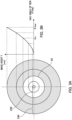
- FIGS. 3 (A), and (B) are diagrams showing optical properties of the first image capturing unit 100 according to the First Embodiment.
- FIG. 3 (A) is a diagram showing an image height y in each half angle of view on the image capturing surface (light receiving surface) of the image capturing element 102 in the form of a contour.
- FIG. 3 (B) is a diagram showing the relationship between the half angle of view ⁇ and the image height y in a first quadrant of FIG. 2 (A) (the projection property of the peripheral-priority wide angle lens 101).
- the peripheral-priority wide angle lens 101 is configured such that the projection properties y ( ⁇ ) of a first angle of view that is less that a predetermined half angle of view ⁇ a and a second angle of view that is greater than the half angle of view ⁇ a are different. Therefore, the peripheral-priority wide angle lens 101 is configured such that when the increase amount for the image height y in relation to the half angle of view ⁇ per unit is made the resolution, this resolution becomes different based on the angle of view (region of the light receiving surface of the image capturing element).
- This localized resolution can be expressed by the differential value dy ( ⁇ )/d ⁇ at the half angle of view ⁇ for the projection property y ( ⁇ ).
- dy ( ⁇ )/d ⁇ at the half angle of view ⁇ for the projection property y ( ⁇ ).
- FIG. 2 (B) shows that in FIG. 2 (B), the larger the slope of the projection property y ( ⁇ ), the higher that the resolution becomes.
- FIG. 2 (A) shows that the larger the interval between the contour lines of the image height y in each half angle of view is, the higher the resolution becomes.
- the rate of increase (the slope of the projection property y ( ⁇ ) in FIG. 3 (B) ) for the image height y is small in a central region that is in the vicinity of the optical axis (the first region).
- the peripheral-priority wide angle lens 101 has a projection property in which the rate of increase for the image height y becomes larger along with the angle of view becoming larger in a peripheral region (a second region) on the outer side of the central region.
- the low resolution region 230 that includes the center corresponds to an angle of view that is less than the half angle of view ⁇ a
- the high resolution region 240 on the outer side of the low resolution region corresponds to an angle of view that is equal to or greater than the half angle of view ⁇ a.
- the angle of view that is less than the half angle of view ⁇ a corresponds to the first angle of view 23 in FIG. 4
- the angle of view that is equal to or greater than the half angle of view ⁇ a corresponds to the second angle of view 24 in FIG. 4 .
- the low resolution region and the high resolution region of the optical system do not need to be configured as concentric circles, and they may also be configured so that both regions have a distorted shape.
- the center of the low resolution region and the center of the high resolution region do not need to be the same.
- the center of the low resolution region and the center of the high resolution region also do not need to be aligned with the center of the light receiving surface of the image capturing element.
- the low resolution region is formed in the vicinity of the optical axis, and the high resolution region is formed on the outer side (the peripheral side) of the low resolution region.
- the peripheral-priority wide angle lens 101 is configured such that when the focal distance is made f, the half angle of view is made ⁇ , the image height on the image surface is made y, the projection property, which represents the relationship between the image height y and the half angle of view ⁇ , is made y( ⁇ ), and ⁇ max is made the greatest half angle of view of the optical system, then the following Formula 1 is fulfilled. That is, the peripheral-priority wide angle lens 101 is configured such that the projection property y ( ⁇ ) is different than 2ftan ( ⁇ /2) (stereographic projection formula).
- a high resolution is obtained in the high resolution region 240, and the increase amount for the image height y in relation to the half angle of view ⁇ per unit is made smaller in the low resolution region 230. Therefore, it is possible to obtain a high resolution in the high resolution region corresponding to the second angle of view for the peripheral side while making the image capturing range the same wide angle of view as for a fisheye lens.
- the image capturing surface (light receiving surface) of the image capturing element 102 comprises a low resolution region 230 (a first region) in which images are captured of subjects that are included in the first angle of view 23, and a high resolution region 240 (a second region) in which images are captured of objects that are included in the second angle of view 24.
- the number of pixels per unit angle of view in the high resolution region 240 (the second region) become larger than the number of pixels per unit angle of view in the low resolution region 230 (the first region). That is, the resolution in the second region corresponding to the second angle of view 24 of the first image capturing unit 100 becomes higher than the resolution in the first region corresponding to the first angle of view 23.
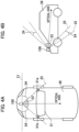
- FIG. 4 (A), and (B) are schematic diagrams that explain the position of the first image capturing unit 100 in the First Embodiment.
- FIG. 4 (A) is a diagram of a vehicle as seen from above
- FIG. 4 (B) is a diagram of a vehicle as seen from the left lateral direction.
- the first image capturing unit 100 is disposed in front of the front glass 31 of the vehicle so as to capture images of the rear direction.
- the automobile 39 is provided with an onboard system (driving assistance system), which is not shown, for supporting a user (a driver, a passenger, or the like), who is also not shown, by using images that have been acquired from the first image capturing unit 100.
- driving assistance system driving assistance system
- the present embodiment shows a case in which the first image capturing unit 100 is disposed in the center of the horizontal direction of the automobile 39, the first image capturing unit 100 does not need to be disposed in the center.
- the first image capturing unit 100 may also be disposed to the left, to the right, or the like of the horizontal direction in front of the automobile 29.
- FIG. 5 is a schematic diagram explaining a first viewpoint video image that has been captured by the first image capturing unit 100 in the First Embodiment. That is, in the First Embodiment, by disposing the first image capturing unit 100 in the manner shown in FIG. 4 , it is possible to capture a first viewpoint video image 51 (a third person viewpoint video image) that captures images of the automobile, and both sides of the automobile's periphery in a third person viewpoint of the outside of the vehicle as is shown in FIG. 5 .
- a first viewpoint video image 51 a third person viewpoint video image
- the peripheral-priority wide angle lens 101 is disposed such that the base of the front glass 31 of the automobile is included in the range of the low resolution region 230. That is, this is disposed such that images are captured of the base of the front glass in the first region.
- this is disposed such that the border 25 between the low resolution region 230 and the high resolution region 240 of the periphery-priority wide angle lens 101 passes through each peak 31a, and 31b that form the base of the front glass 31 of the automobile.
- the first image capturing unit 100 acquires an image capturing signal in which an optical image has been captured, and outputs a captured video image in which the image capturing signal has been RAW photo processed to the synthesis processing unit 300.
- the first image capturing unit 100 has an image processing unit 103, and the image processing unit 103 De-Bayer processes an R, G, B color image capturing signal that has been input according to a Bayer array color filter from the image capturing element 102, and then converts this to a captured video image with an RGB cluster format.
- the image processing unit 103 performs various types of correction processing such as white balance adjustments, gain/offset adjustments, gamma processing, color matrix processing, reversible compression processing, and the like.
- white balance adjustments gain/offset adjustments
- gamma processing color matrix processing
- reversible compression processing and the like.
- RGB image that has been RAW photo processed is formed without performing irreversible compression processing or the like.
- the image processing unit 103 may also have a distortion aberration correction function.
- the lateral direction image capturing unit 200 is a camera that is used for the purpose of an electronic side mirror that functions as a camera monitor system, and has both a right lateral direction camera 210 on the right lateral direction of the vehicle, and a left lateral direction camera 220 on the left lateral direction of the vehicle.
- the right lateral direction camera 210 and the left lateral direction camera 220 are general onboard cameras that have been attached to a vehicle in the image capturing direction such that the regulations regarding indirect visibility for an electronic side mirror in a camera monitor system are fulfilled.
- the right lateral direction camera 210 captures right lateral direction video images
- the left lateral direction camera 220 captures left lateral direction video images.
- FIG. 6 (A), and (B) are schematic diagrams explaining a field of view range for a class III, and II that are both stipulated by UN-R46, and show, in relation to the indirect visibility of the side mirror, a field of view range for the side mirror for class II and a field of view range for the side mirror for class III, which are stipulated by UN-R46.
- the right lateral direction camera 210 and the left lateral direction camera 220 are attached so as to be able to capture images of a field of view range for the class III, which is shown by the oblique lines in FIG. 6 (A) .
- the right lateral direction camera 210 and the left lateral direction camera 220 are attached so as to capture images of the field of view range for the class II, which is shown by the oblique lines in FIG. 6 (B) .
- FIGS. 6 (A), and (B) show a case in which the driver's seat is on the left side of the vehicle, this is the same even if the driver's seat is on the right side of the vehicle.
- the right lateral direction camera 210 outputs a right lateral direction video image and the left lateral direction camera 220 outputs a left lateral direction video image to the synthesis processing unit 300.
- the synthesis processing unit 300 has a video image extracting unit 310, a video image output unit 320, and the input switching unit 330.
- the input switching unit 330 outputs a switching signal that indicates switching between each video image to the video image output unit 320.
- the synthesis processing unit 300 has a CPU and a program memory that stores a computer program, neither of which are shown, and controls the entirety of the vehicle periphery image capturing system 1000.
- the synthesis processing unit 300 has a storage unit that is not shown, and generates car navigation video images based on each type of car navigation information such as, for example, periphery maps, traffic regulations, destinations, and the like that have been held in the storage unit, and outputs this to the car navigation monitor 401 via the video image output unit 320.
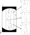
- FIG. 7 is a schematic diagram explaining a range in which each video image from the first viewpoint is extracted by the video image extracting unit 310 according to the First Embodiment.
- the video extracting unit 310 performs the extraction of a first viewpoint center video image 71, a first viewpoint right lateral direction video image 72, and a first viewpoint left lateral direction video image 73 as shown in FIG. 7 from a first viewpoint video image 51 that has been acquired from the first image capturing unit 100.
- the first viewpoint center video image is extracted so as to include the entirety of the front glass of the automobile, and both the right lateral direction and the left lateral direction of the automobile.
- the first viewpoint center video image 71 is made almost the entire range of the first viewpoint video image 51, it is sufficient if this is a video image of a range with a predetermined width that includes the center of the first viewpoint image 51.
- the first viewpoint right lateral direction video image 72 is extracted such that it includes at least a portion of the front glass of the automobile that serves as a movable apparatus, and the right lateral direction from when the driver of the automobile is facing the front of the vehicle (the direction of the front glass). That is, the first image capturing unit 100 that serves as an image capturing unit is able to capture images of a portion or the entirety of the front glass of a movable apparatus and at least one of a region on the right side of the movable apparatus and a region on the left side of the movable apparatus at the same time.
- the first viewpoint left lateral direction video image 73 is extracted so as to include at least a portion of the front glass of the automobile and the left lateral direction from when the operator of the automobile is facing the front of the vehicle (the direction of the front glass).
- the video image extracting unit 310 executes a video image extraction step configured to extract a region comprising the front glass, and at least one of a region on the right side of the movable apparatus and a region on the left side of the movable apparatus as an extracted video image from the video image that has been captured by the image capturing unit.
- the video image output unit 320 executes a video image output step configured to switch between a video image that has been captured by the image capturing unit and an extracted video image and output this to a display unit based on control information from the switching signal input unit 500.
- the video image extracting unit 310 outputs each of the first viewpoint center video image 71, the first viewpoint right lateral direction video image 72, and the first viewpoint left lateral direction video image 73 to the video image output unit 320.
- the video image output unit 320 has each output IF of the car navigation video image output IF 321, the right lateral direction video image output IF 322, and the left lateral direction video image output IF 323 as was explained above.
- the car navigation video image output IF 321 switches between one of the car navigation video image or the first viewpoint center video image 71 based on a switching signal that has been input from the input switching unit 330, outputs the video image to the display unit 400, and displays it on the car navigation monitor 401.
- the car navigation video image output IF 321 outputs a car navigation video image
- the car navigation video image output IF 321 outputs a video image by switching to the first viewpoint center video image 71.
- the right lateral direction video image output IF 322 switches between either of the right lateral direction video direction video image and the first viewpoint right lateral direction video image 72, outputs one of these to the display unit 400 and displays the output video image on the right lateral direction display unit 402 based on the switching signal that has been input from the input switching unit 330. That is, during the time in which a switching signal that indicates the display of the first viewpoint right lateral direction video image 72 has not been input, the right lateral direction video image output IF 322 outputs the right lateral direction video image from the right lateral direction camera 210.
- the right lateral direction video image output IF 322 outputs a video image by switching to the first viewpoint right lateral direction video image 72.
- the left lateral direction video image output IF 323 switches between the left lateral direction video image or the first viewpoint left lateral direction video image 73 and outputs one of these to the display unit 400 and displays the output video image on the left lateral direction display unit 403 based on a switching signal that has been input from the input switching unit 330. That is, during the time in which a switching signal that indicates the display of the first viewpoint left lateral direction video image 73 has not been input, the left lateral direction video image output IF 323 outputs the left lateral direction video image from the left lateral direction camera 220.
- the left lateral direction video image output IF 323 outputs a video image by switching to the first viewpoint left lateral direction video image.
- each of the video images that are output to the display unit 400 from the video image output unit 320, the first viewpoint center video image 71, the right lateral direction video image, the first viewpoint right lateral direction video image 72, the left lateral direction video image and the first viewpoint left lateral direction video image 73 are left to right inverted such that the left to right of the display unit 400 is associated with the left to right of the video image that has been captured.
- the input switching unit 330 generates a switching signal that indicates the switching of each video image to be displayed on the display unit 400 based on the input of vehicle control information from the switching signal input unit 500.
- the input switching unit 330 has a register that detects and holds the input/lack of input for the R (reverse) of the shift lever 501, the input/lack of input of the hazard button 502, and the right input/left input/lack of input of the direction indicator 503 to serve as control information for the vehicle.
- the input switching unit 330 In addition, during a time in which there is, for example an input for the R of the shift lever 501, or an input for the hazard button 502, the input switching unit 330 generates a switching signal for a high level that indicates the display of the first viewpoint center video image 71. Conversely, during a time in which there is no input for the R for the shift lever 501, or an input for the hazard button 502, the input switching unit 330 generates a switching signal for a low level.
- the input switching unit 330 generates a switching signal for a high level that indicates the display of the first viewpoint right lateral direction video image 72.
- the input switching unit 330 generates a switching signal for a high level that indicates a display of the first viewpoint left lateral direction video image 73.
- the switching unit 330 Conversely, in a case in which there is neither a right input or a left input for the direction indicator 503, the switching unit 330 generates a switching signal for a low level.
- the conditions for generating a switching signal are not limited to the conditions that have been described above.
- the conditions for generating a high level switching signal that indicates the display of the first viewpoint right lateral direction video image 72 may also be made a time in which there is no input of an R for the shift lever 501, and also no input of the hazard button 502, while there is a right input for the direction indicator.
- a low level switching signal may also be generated even if there is a right input for the direction indicator 503.
- the conditions for generating a switching signal for a high level that indicates the display of a first viewpoint left lateral direction video image 73 may also be made during a time in which there is no input of an R for the shift level 501 as well as no input for the hazard button 502, but there is a left input for the direction indicator.
- a switching signal for a low level may also be generated even if there is a left input for the direction indicator 503 in a case in which there is an input for an R for the shift lever 501 or an input for the hazard button 502.
- the first viewpoint right lateral direction video image 72 or the first viewpoint left lateral direction video image is displayed only when the first viewpoint center video image 71 is not being displayed.
- the state of the shift lever 501 that is detected in the register may also be made to detect and hold the input/lack of input of an R or P (park).
- a switching signal for a high level that indicates the display of the first viewpoint center video image 71 is also generated at a time when there is an input of a P for the shift lever 501, and the first viewpoint center video image is displayed.
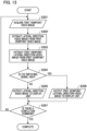
- FIG. 8 is a flowchart showing an example of an image capturing method in which the synthesis processing unit 300 outputs a car navigation video image in the First Embodiment
- FIG. 9 is a flowchart showing an example of an image processing method in which the synthesis processing unit 300 outputs a lateral direction video image in the First Embodiment.
- the processing for each step in FIG. 8 and FIG. 9 is performed in in order by the CPU, which functions as a computer and is not shown, of the synthesis processing unit 300 executing the computer program, which has been stored on the memory that is also not shown.
- step S101 the first viewpoint video image 51, which has captured a region comprising the left lateral direction, the front glass, and the right lateral direction of the automobile is acquired from the first image capturing unit 100.
- the first viewpoint video image 51 is input into the video image extracting unit 310. After this, the processing proceeds to step S102.
- each type of car navigation information such as a peripheral map, traffic regulations, a destination, and the like is acquired from a database, which is not shown, and a car navigation video image is generated.
- the car navigation video image is input to the video image output unit 320.
- the first viewpoint center video image 71 is extracted from the first viewpoint video image 51.
- the first viewpoint center video image 71 is extracted so as to include the entirety of the front glass of the automobile, and both the right lateral direction and the left lateral direction of the automobile.
- the first viewpoint center video image 71 is input into the video image output unit 320. After this, the processing proceeds to step S104.
- step S104 it is determined whether or not the switching signal from the switching signal input unit 500 that indicates the display of the first viewpoint center video image 71 is high. As was described above, the switching signal becoming high is made during a time in which, for example, there is at least one of an input of an R or an input of a P input for the shift lever 501, or an input for the hazard button 502. If the determination results are No, the processing proceeds to step S105, and if the determination results are yes, the processing proceeds to step S106.
- step S105 the car navigation video is output to the display unit 400. After this, the processing proceeds to step S107.
- step S106 the first viewpoint center video image 71 is output to the display unit 400. After this, the processing proceeds to step S107.
- step S107 it is determined whether or not there has been a completion command from the user. If the determination results are no, then the processing proceeds to step S101, and if the determination results are yes, then the processing for the flow in FIG. 8 is completed. Note that for example, the completion command from the user is made yes in a case in which, in a state in which the on/off for the engine of the vehicle is input into the synthesis processing unit 300, the synthesis processing unit 300 has detected that the engine is off.
- step S201 the first viewpoint video image 51, which has captured a range including the left lateral direction, the front glass, and the right lateral direction of the automobile is acquired from the first image capturing unit 100.
- the first viewpoint video image 51 is input into the video image extracting unit 310. After this, the processing proceeds to step S202.
- step S202 the right lateral direction video image and the left lateral direction video image are acquired from the lateral direction image capturing unit 200.
- the right lateral direction video image and the left lateral direction video image are input into the video image output unit 320. After this, the processing proceeds to step S203.
- the first viewpoint right lateral direction video image 72 and the first viewpoint left lateral direction video image 73 are extracted from the first viewpoint video image 51.
- the first viewpoint right lateral direction video image 72 is extracted so as to include at least a portion of the front glass of the automobile and the right lateral direction of the automobile.
- the first viewpoint left lateral direction video image 73 is extracted so as to include at least a portion of the front glass of the automobile and the left lateral direction of the automobile.
- the first viewpoint right lateral direction video image 72 and the first viewpoint left lateral direction video image 73 are input into the video image output unit 320.
- the processing proceeds to step S204.
- step S204 it is determined whether or not the switching signal that indicates the display of the first viewpoint right lateral direction video image 72 or of the first viewpoint left lateral direction video image 73 from the switching signal input unit 500 is high.
- the switching signal becomes high in a case in which, for example, there is no input for any of an R or a P for the shift lever 501, and there is no input for the hazard button 502, while there is a right input or a left input for the direction indicator 503. If the determination results are no, then the processing proceeds to step S205, and if the determination results are yes, then the processing proceeds to step S206.
- step S205 the right lateral direction video image or the left lateral direction video image is output to the display unit 400.
- step S207 the processing proceeds to step S207.
- step S206 the first viewpoint right lateral direction video image 72 or the first viewpoint left lateral direction video image 73 is output to the display unit 400 according to the right input or the left input of the direction indicator 503. After this, the processing proceeds to step S207.
- step S207 it is determined whether or not there has been a completion command from the user. If the determination results are No, the processing proceeds to step S201, and if the determination results are Yes, the processing for the flow in FIG. 9 is completed. As was described above, in the present embodiment, it is possible to display each video image for the first viewpoint on each monitor without performing the processing for projection conversion for each video image or video image synthesis.
- image capturing is performed such that images are captured of the front direction and the reverse direction of the automobile so as to include the right lateral direction, the front glass, and the left lateral direction from the first viewpoint that is in front of the front glass of the automobile. Therefore, it is possible to capture video images of both the automobile and the periphery of the automobile at the same time.
- control information for the vehicle may also be the rotation direction and rotation amount for a handle for use in steering, vehicle speed, the acceleration rate of the vehicle, car navigation information, and the like. That is, the control information for the vehicle includes at least one of an input of an R or an input of a P for the shift lever 501, the input for the hazard button 502, the input for the direction indicator 503, the rotation direction and rotation amount for the handle for steering, the vehicle speed, the degree of acceleration for the vehicle, or car navigation information.
- FIG. 10 is a functional block diagram showing a configurational example of a vehicle periphery image capturing system 1000' according to the Second Embodiment.
- functional blocks that have the same reference number as functional blocks in FIG. 1 are functional blocks that have the same functions.
- 210' is a right lateral direction camera
- 220' is a left lateral direction camera
- 300' is a synthesis processing unit
- 310' is a video image extracting unit
- the right lateral direction camera 210' and the left lateral direction camera 220' are attached such that they are able to capture images in a range that fulfills the field of view range for a side mirror for the class II and the class III as stipulated by UN-R46 with respect to the indirect visibility for each electronic side mirror.
- FIG. 11 is a schematic diagram explaining the position of the lateral direction image capturing unit 200 according to the Second Embodiment.
- the right lateral side camera 210' which serves as a second image capturing unit, is disposed on the right lateral side from the center of the front glass of the automobile, such that it includes the right lateral side and the front glass 31 of the automobile and such that the optical axis faces the rear direction of the automobile.
- the image capturing unit of the Second Embodiment captures images of a portion of the front glass and a region on the right side of the movable apparatus (including the immediate right side of the vehicle) at the same time in a case in which a portion of the right side of the front glass is being imaged captured.
- the right lateral side direction camera 210' has a periphery-priority wide angle lens with an optical property such as that shown in FIGS. 3 (A), and (B) , and an image capturing element.
- the left lateral direction camera 220' that serves as a first image capturing unit, as is shown in FIG. 11 , is disposed towards the left lateral direction from the center of the front glass of the automobile so as to include the left lateral side and the front glass 31 of the automobile, and such that the optical axis faces the rear direction of the automobile.
- the image capturing unit of the Second Embodiment captures images of a portion of the front glass and a region on the left side of the movable apparatus (including the immediate left side of the automobile) at the same time in a case in which a portion of the left lateral side of the front glass is being image captured.
- the left lateral direction camera 220' also has a peripheral-priority wide angle lens with an optical characteristic such as that shown in FIGS. 3 (A), and (B) , and an image capturing element.
- the video image extracting unit 310' of FIG. 10 has a right lateral direction video image extracting unit 311 and a left lateral direction video image extracting unit 312, and is able to extract a video image corresponding to an electronic side mirror.
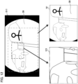
- FIG. 12 is a schematic diagram explaining a first viewpoint video image that has been image captured using the arrangement of FIG. 11 in the Second Embodiment.
- the right lateral direction video image extracting unit 311 is made as is shown in FIG. 12 , and performs the extraction of each video image of the right lateral direction video image 121 and the first viewpoint right lateral direction video image 72' from the first viewpoint video image 511 of the right lateral side that has been acquired from the right lateral direction camera 210'.
- the right lateral direction video image 121 is the same video image as a general electronic side mirror, and as was described above, is extracted so as to include a range that fulfills the field of vision range for a side mirror for the class II and the class III as stipulated by UN-R46 in relation to the indirect sight of an electronic side mirror.
- the first viewpoint right lateral side direction video image 72' is extracted so as to include at least a portion of the front glass of the automobile and the right lateral side of the automobile 39.
- the left lateral direction video image extracting unit 312 is not shown, it is the same as the right lateral direction video image extracting unit 311 with the only difference being that the right and left are changed.
- the right lateral direction video image extracting unit 311 outputs the right lateral direction video image 121 or the first viewpoint right lateral direction video image 72' to the right lateral direction video image output IF 322.
- the left lateral direction video image extracting unit 312 outputs the left lateral direction video image or the first viewpoint left lateral direction video image 73' to the left lateral direction video image output IF 323.
- FIG. 13 is a flowchart showing an example of an image capturing method in which a synthesis processing unit 300' outputs a lateral direction video image in the Second Embodiment, and this shows the operations in which the synthesis processing unit 300' of the Second Embodiment switches between each video image of the right lateral direction video image or the left lateral direction video image and outputs this to the display unit 400. Note that each processing in FIG. 13 is performed in order by a CPU that is not shown and that serves as a computer of the synthesis processing unit 300' executing a computer program that has been stored on a memory that is also not shown.
- the processing for the steps S203 to S207 in FIG. 13 is the same as the processing for the steps S203 to S207 in FIG. 9 , and therefore an explanation thereof has been omitted.
- the first viewpoint video image 511 which captures images of a range that includes the right lateral direction and the front glass of the automobile, is acquired from the right lateral direction camera 210'.
- the first viewpoint video image 512 which has captured images of a range including the left lateral direction and the front glass of the automobile, is acquired from the left lateral direction camera 220'.
- the first viewpoint video images 511, and 512 are input into the video image extracting unit 310. After this, the processing proceeds to step S202'.
- a right lateral direction video image and a left lateral direction video image are extracted from the first viewpoint video image 511, and 512.
- the right lateral direction video image and the left lateral direction video image are extracted so as to include the range that is stipulated by UN-R46 in relation to the indirect visibility of each electronic side mirror.
- the right lateral direction video image and the left lateral direction video image are input into the video image output unit 320. After this, the processing proceeds to step S203.
- the right lateral direction camera 210' is disposed in the right lateral direction of the front glass of the automobile
- the left lateral direction camera 220' is disposed in the left lateral direction of the front glass of the automobile.
- a range in the rear direction of the automobile is image captured by the right lateral direction camera 210' so as to include the right lateral direction and the front glass of the automobile.
- a range in the rear direction of the automobile is image captured by the left lateral direction camera 220' such that the left lateral direction and the front glass of the automobile are included.
- the above-described embodiments are not limited to an automobile, and the movable apparatus may be any kind of apparatus that can be moved such as a motorcycle, a ship, an airplane, a robot, a drone, or the like.
- a computer program realizing the function of the embodiments described above may be supplied to the image capturing apparatus or the like through a network or various storage media. Then, a computer (or a CPU, an MPU, or the like) of the image capturing apparatus or the like may be configured to read and execute the program. In such a case, the program and the storage medium storing the program configure the present invention.
Landscapes
- Engineering & Computer Science (AREA)
- Multimedia (AREA)
- Signal Processing (AREA)
- Mechanical Engineering (AREA)
- Physics & Mathematics (AREA)
- General Physics & Mathematics (AREA)
- Optics & Photonics (AREA)
- Closed-Circuit Television Systems (AREA)
- Studio Devices (AREA)
Abstract
In order to make it easier for a user of a movable apparatus to grasp the relationship between an automobile as a movable apparatus and the peripheral conditions thereof, an image capturing apparatus that is disposed on the movable apparatus comprises an image capturing unit configured to capture images of a portion or the entirety of a front side transparent member of the movable apparatus and at least one of a right lateral region and a left lateral region of the movable apparatus at the same time as a video image, wherein the image capturing unit is disposed in front of the front side transparent member of the movable apparatus.
Description
- The present invention relates to an image capturing apparatus, a movable apparatus, an image capturing method, a storage medium, and the like.
- In recent years, there has been a need to replace the room mirrors and side mirrors that are installed in vehicles with electronic mirrors. An electronic side mirror system is able to capture images in a wide range including regions that would be blind spots in traditional, physical side mirrors.
- In contrast, as in, for example,
Japanese Unexamined Patent Application, First Publication No. 2017-224881 - In a case in which a driver would like to understand the peripheral conditions of an automobile from an electronic side mirror video image, images are only captured of at least a portion the side of the automobile, and therefore, it is difficult to grasp the relationship between the automobile and its peripheral conditions. In contrast, when implementing a technology such as that in
Japanese Unexamined Patent Application, First Publication No. 2017-224881 - An image capturing apparatus according to one aspect of the present invention is an image capturing apparatus that is disposed on a movable apparatus, wherein the image capturing apparatus comprises: an image capturing unit configured to capture images of a portion or the entirety of a front-side transparent member of the movable apparatus, and at least one of a right lateral direction region and a left lateral direction region of the movable apparatus at the same time as video images; wherein the image capturing unit is disposed in front of the front-side transparent member of the movable apparatus.
- Further features of the present invention will become apparent from the following description of embodiments with reference to the attached drawings.
-
-
FIG. 1 is a functional block diagram that shows a configurational example of a vehicle periphery image capturingsystem 1000 according to a First Embodiment. -
FIG. 2 is a schematic diagram explaining an optical characteristic of a peripheral-prioritywide angle lens 101 according to the First Embodiment. -
FIG. 3A, and FIG. 3B are diagrams showing optical characteristics of a firstimage capturing unit 100 according to the First Embodiment. -
FIG. 4A and FIG. 4B are schematic diagrams explaining the position of the firstimage capturing unit 100 according to the First Embodiment. -
FIG. 5 is a schematic diagram explaining a first viewpoint video image that has been image captured by the firstimage capturing unit 100 in the First Embodiment. -
FIG. 6A, and FIG. 6B are schematic diagrams explaining field of vision ranges for the class III and class II that are stipulated by UN-R46 -
FIG. 7 is a schematic diagram explaining a range that is extracted from each video image from the first viewpoint by a videoimage extracting unit 310 according to the First Embodiment. -
FIG. 8 is a flowchart showing an example of an image capturing method in which asynthesis processing unit 300 outputs a car navigation video image in the First Embodiment. -
FIG. 9 is a flowchart showing an example of an image capturing method in which asynthesis processing unit 300 outputs a lateral direction video image in the First Embodiment. -
FIG. 10 is a functional block diagram showing a configurational example of a vehicle periphery image capturing system 1000' according to a Second Embodiment. -
FIG. 11 is a schematic diagram that explains the position of a lateral directionimage capturing unit 200 according to the Second Embodiment. -
FIG. 12 is a schematic diagram explaining a first viewpoint video image that has been captured in the position ofFIG. 11 in the Second Embodiment. -
FIG. 13 is a flowchart explaining an example of an image capturing method in which asynthesis processing unit 300 outputs a lateral direction video image in the Second Embodiment. - Hereinafter, with reference to the accompanying drawings, favorable modes of the present invention will be described using Embodiments. In each diagram, the same reference signs are applied to the same members or elements, and duplicate descriptions will be omitted or simplified.
- In the First Embodiment, a method is explained in which, by disposing a camera facing forward and in the opposite direction in front of a front side transparent member such as the front glass of an automobile, or the like, a video image is displayed such that it is possible for a user to understand the relationship between the automobile and its peripheral conditions without the need for complex processing.
- Note that although in the following explanation, an example is explained using the front glass (the front window) as the front side transparent member, the front side transparent member does not need to be made from glass, and may, for example, also be a transparent member consisting of resin or the like.
-
FIG. 1 is a functional block diagram showing a configurational example of a vehicle periphery image capturingsystem 1000 according to the First Embodiment. Note that a portion of the functional blocks that are shown inFIG. 1 are realized by a CPU or the like that serves as a computer, which is not shown and is included in the vehicle periphery image capturingsystem 1000, executing a computer program that has been stored on a memory that serves as a storage medium, which is also not shown. - However, it may also be made such that a portion or the entirety thereof is realized by hardware. As the hardware, an application specific integrated circuit (ASIC), a processor (a reconfigurable processor, a DSP), or the like can be used.
- In addition, each of the functional blocks that are shown in
FIG. 1 do not need to be encased in the same body, and they may also be configured by separate devices that have been connected to each other via signal paths. Note that the above explanation in relation toFIG. 1 also applies toFIG. 10 in the same manner. - The vehicle periphery image capturing
system 1000 is disposed on a vehicle (automobile) that serves as a movable apparatus, and functions as an image capturing apparatus. The vehicle periphery image capturingsystem 1000 has a firstimage capturing unit 100, a lateral directionimage capturing unit 200, asynthesis processing unit 300, adisplay unit 400, and a switchingsignal input unit 500. - Note that the entirety of the vehicle periphery image capturing
system 1000 that serves as an image capturing apparatus and is shown inFIG. 1 does not need to be disposed on a movable apparatus, and a portion may also be disposed on, for example, an external terminal or the like that is able to communicate wirelessly. That is, for example, thesynthesis processing unit 300 and thedisplay unit 400, and the like may also be disposed on an external terminal for monitoring or controlling the movements of the movable apparatus. - The first
image capturing unit 100 that serves as an image capturing unit is disposed in front of the front glass of an automobile, is installed such that the optical axis faces the rear direction of the vehicle that serves as the movable apparatus, and is a wide angle camera that is able to capture images from the left lateral direction to the right lateral direction of the automobile. - Note that the left lateral direction and the right lateral direction in the following explanation mean the left lateral direction and the right lateral direction when the front of the vehicle (the direction of the front glass) is seen from the driver's seat of the automobile. In addition, the front direction means the direction of the front glass (front window) as seen from the driver's seat of the automobile and the rear direction means the direction of the rear window as seen from the driver's seat of the automobile.
- The lateral direction
image capturing unit 200 is, for example, a camera that has been installed on the lateral side of the vehicle for use as an electronic side mirror, and comprises a rightlateral direction camera 210 and a leftlateral direction camera 220. Note that the rightlateral direction camera 210 and the leftlateral direction camera 220 are for example, disposed in the right end vicinity and the left end vicinity of the front glass of the vehicle, and are disposed so as to capture images of both the right rear direction and the left rear direction of the vehicle. - The
synthesis processing unit 300 is, for example, a computer that is installed in the vehicle, and comprises a videoimage extracting unit 310, a videoimage output unit 320, aninput switching unit 330, and the like. The videoimage output unit 320 comprises a car navigation video image output IF 321, a right lateral direction video image output IF 322, and a left lateral direction video image output IF 323. - The
display unit 400 comprises, for example, a car navigation monitor 401 for use in a car navigation system, and a right lateraldirection display unit 402 and a left lateraldirection display unit 403 for use as electronic side mirrors that have been installed on the right front direction and the left front direction of the driver's seat. - The switching
signal input unit 500 comprises, for example, ashift lever 501 for an automobile, ahazard button 502, and adirection indicator 503. In addition, the switchingsignal input unit 500 outputs each type of information that has been input into each in-vehicle component to be described below such as driving state information, hazard light information, drive direction information, direction indication information, and the like to thesynthesis processing unit 300. - In this context, the switching
signal input unit 500 functions as a control information acquisition unit that executes a control information acquisition step that acquires control information for a movable apparatus. - The
shift lever 501 has driving state information such as, for example, parking P/reverse R/drive D/neutral N. Thehazard button 502 has hazard light information such as, for example, a hazard light being illuminated/unilluminated. Thedirection indicator 503 has direction indicating information such as, for example, left/right/not indicated. - The first
image capturing unit 100 has, a wide angle lens with a characteristic shape that will be described below (referred to below as a peripheral-priority wide angle lens 101), and animage capturing element 102 such as, for example, a CMOS image sensor, a CCD image sensor, and the like. -
FIG. 2 is a schematic diagram that explains an optical characteristic of the peripheral-prioritywide angle lens 101 according to the First Embodiment. As is shown inFIG. 2 , the peripheral-prioritywide angle lens 101 has animage circle 21 that is able to capture wide angle images at 180°, and is disposed in animage capturing region 22, which is a light receiving surface of theimage capturing element 102, so as to be able to capture images at 180° horizontally. - In addition, the peripheral-priority
wide angle lens 101 has different image forming magnifications between a first angle of view (23 ofFIG. 4 ) that includes the center of the optical axis, and a second angle of view (24 ofFIG. 4 ) that is more towards the peripheral side than the first angle of view. In addition, as is shown inFIG. 2 , within theimage circle 21, alow resolution region 23, which captures images of objects that are included in the first angle of view, and a high resolution region 240 (a second region), which captures images of objects that are included in the second angle of view, are formed. - In addition, the peripheral-priority
wide angle lens 101 has an optical property that is able to capture images at a higher resolution the closer to the edges of the lens that the image becomes. 25 is the border between thelow resolution region 230 and thehigh resolution region 240. -
FIGS. 3 (A), and (B) are diagrams showing optical properties of the firstimage capturing unit 100 according to the First Embodiment.FIG. 3 (A) is a diagram showing an image height y in each half angle of view on the image capturing surface (light receiving surface) of theimage capturing element 102 in the form of a contour.FIG. 3 (B) is a diagram showing the relationship between the half angle of view θ and the image height y in a first quadrant of FIG. 2 (A) (the projection property of the peripheral-priority wide angle lens 101). - As is shown in
FIG. 3 (B) , the peripheral-prioritywide angle lens 101 is configured such that the projection properties y (θ) of a first angle of view that is less that a predetermined half angle of view θa and a second angle of view that is greater than the half angle of view θa are different. Therefore, the peripheral-prioritywide angle lens 101 is configured such that when the increase amount for the image height y in relation to the half angle of view θ per unit is made the resolution, this resolution becomes different based on the angle of view (region of the light receiving surface of the image capturing element). - This localized resolution can be expressed by the differential value dy (θ)/dθ at the half angle of view θ for the projection property y (θ). For example, it can be said that in FIG. 2 (B), the larger the slope of the projection property y (θ), the higher that the resolution becomes. In addition, FIG. 2 (A) shows that the larger the interval between the contour lines of the image height y in each half angle of view is, the higher the resolution becomes.
- In addition, in the peripheral-priority
wide angle lens 101 of the present embodiment, the rate of increase (the slope of the projection property y (θ) inFIG. 3 (B) ) for the image height y is small in a central region that is in the vicinity of the optical axis (the first region). In addition, the peripheral-prioritywide angle lens 101 has a projection property in which the rate of increase for the image height y becomes larger along with the angle of view becoming larger in a peripheral region (a second region) on the outer side of the central region. - In
FIG. 3 (A) , thelow resolution region 230 that includes the center corresponds to an angle of view that is less than the half angle of view θa, and thehigh resolution region 240 on the outer side of the low resolution region corresponds to an angle of view that is equal to or greater than the half angle of view θa. In addition, the angle of view that is less than the half angle of view θa corresponds to the first angle ofview 23 inFIG. 4 , and the angle of view that is equal to or greater than the half angle of view θa corresponds to the second angle ofview 24 inFIG. 4 . - Note that the property that is shown in
FIG. 2 is one example, and the present disclosure is not limited thereto. For example, the low resolution region and the high resolution region of the optical system do not need to be configured as concentric circles, and they may also be configured so that both regions have a distorted shape. - In addition, the center of the low resolution region and the center of the high resolution region do not need to be the same. In addition, the center of the low resolution region and the center of the high resolution region also do not need to be aligned with the center of the light receiving surface of the image capturing element. In the optical system of the present embodiment, it is sufficient if the low resolution region is formed in the vicinity of the optical axis, and the high resolution region is formed on the outer side (the peripheral side) of the low resolution region.
- The peripheral-priority
wide angle lens 101 is configured such that when the focal distance is made f, the half angle of view is made θ, the image height on the image surface is made y, the projection property, which represents the relationship between the image height y and the half angle of view θ, is made y(θ), and θmax is made the greatest half angle of view of the optical system, then the followingFormula 1 is fulfilled. That is, the peripheral-prioritywide angle lens 101 is configured such that the projection property y (θ) is different than 2ftan (θ/2) (stereographic projection formula).

- It is thereby possible to control the aspect ratio of the radiation direction and the circumference direction in relation to the optical axis, and therefore, different than in a conventional fisheye lens or the like, it is possible to obtain images with a high resolution and a low amount of distortion in the peripheral region while having an angle of view that is a wide angle.
- In addition, by fulfilling the
Formula 1, it is possible to increase the resolution in thehigh resolution region 240 in comparison to an optical system with a stereographic projection formula. Note that if the upper limit of theFormula 1 is exceeded, the resolution in thehigh resolution region 240 will decrease, and the difference in resolutions between thehigh resolution region 240 and thelow resolution region 230 will decrease, making this not preferable. - In addition, if a value falls below the lower limit of the
Formula 1, it will become difficult to favorably correct aberrations such as field curvature and the like, and this is therefore also not preferable. Note that the above-explainedFormula 1 is one example, and the optical system in the present embodiment is not limited to theFormula 1. - In the manner described above, in the optical system of the First Embodiment, a high resolution is obtained in the
high resolution region 240, and the increase amount for the image height y in relation to the half angle of view θ per unit is made smaller in thelow resolution region 230. Therefore, it is possible to obtain a high resolution in the high resolution region corresponding to the second angle of view for the peripheral side while making the image capturing range the same wide angle of view as for a fisheye lens. - In addition, in the present embodiment, the high resolution region has a projection property that is similar to the stereographic radiation formula (y=2 × f × tan(0/2), which is the projection property for an optical system for use in general image capturing. Therefore, it becomes possible to generate a highly detailed image with low optical distortion in the high resolution region.
- As was explained above, in the First Embodiment, the image capturing surface (light receiving surface) of the
image capturing element 102 comprises a low resolution region 230 (a first region) in which images are captured of subjects that are included in the first angle ofview 23, and a high resolution region 240 (a second region) in which images are captured of objects that are included in the second angle ofview 24. - In addition, the number of pixels per unit angle of view in the high resolution region 240 (the second region) become larger than the number of pixels per unit angle of view in the low resolution region 230 (the first region). That is, the resolution in the second region corresponding to the second angle of
view 24 of the firstimage capturing unit 100 becomes higher than the resolution in the first region corresponding to the first angle ofview 23. -
FIG. 4 (A), and (B) are schematic diagrams that explain the position of the firstimage capturing unit 100 in the First Embodiment.FIG. 4 (A) is a diagram of a vehicle as seen from above, andFIG. 4 (B) is a diagram of a vehicle as seen from the left lateral direction. As is shown inFIG. 4 (A), and (B) , the firstimage capturing unit 100 is disposed in front of thefront glass 31 of the vehicle so as to capture images of the rear direction. - Therefore, it is possible to capture images of the rear direction including the surroundings of the front glass of the automobile such that, for example, the upper portion of the front bonnet, the left lateral direction, the front glass, and the right lateral direction of the automobile are included.
- In addition, the
automobile 39 is provided with an onboard system (driving assistance system), which is not shown, for supporting a user (a driver, a passenger, or the like), who is also not shown, by using images that have been acquired from the firstimage capturing unit 100. Note that although the present embodiment shows a case in which the firstimage capturing unit 100 is disposed in the center of the horizontal direction of theautomobile 39, the firstimage capturing unit 100 does not need to be disposed in the center. In addition, the firstimage capturing unit 100 may also be disposed to the left, to the right, or the like of the horizontal direction in front of the automobile 29. -
FIG. 5 is a schematic diagram explaining a first viewpoint video image that has been captured by the firstimage capturing unit 100 in the First Embodiment. That is, in the First Embodiment, by disposing the firstimage capturing unit 100 in the manner shown inFIG. 4 , it is possible to capture a first viewpoint video image 51 (a third person viewpoint video image) that captures images of the automobile, and both sides of the automobile's periphery in a third person viewpoint of the outside of the vehicle as is shown inFIG. 5 . - In addition, it is possible to capture images with a high resolution by allocating a large number of pixels to the peripheral of the automobile in the left lateral direction and the right lateral direction while capturing images of the automobile by using the peripheral-priority
wide angle lens 101. In addition, at this time, the peripheral-prioritywide angle lens 101 is disposed such that the base of thefront glass 31 of the automobile is included in the range of thelow resolution region 230. That is, this is disposed such that images are captured of the base of the front glass in the first region. - More preferably, this is disposed such that the
border 25 between thelow resolution region 230 and thehigh resolution region 240 of the periphery-prioritywide angle lens 101 passes through eachpeak front glass 31 of the automobile. - By using this arrangement, it is possible to capture images by appropriately allocating the high resolution region to the periphery of the automobile while making the ratio from among the
first viewpoint 51 that is taken up by the automobile smaller. - Returning to
FIG. 1 , in addition, the firstimage capturing unit 100 acquires an image capturing signal in which an optical image has been captured, and outputs a captured video image in which the image capturing signal has been RAW photo processed to thesynthesis processing unit 300. Specifically, the firstimage capturing unit 100 has animage processing unit 103, and theimage processing unit 103 De-Bayer processes an R, G, B color image capturing signal that has been input according to a Bayer array color filter from theimage capturing element 102, and then converts this to a captured video image with an RGB cluster format. - Furthermore, the
image processing unit 103 performs various types of correction processing such as white balance adjustments, gain/offset adjustments, gamma processing, color matrix processing, reversible compression processing, and the like. However, a so-called RGB image that has been RAW photo processed is formed without performing irreversible compression processing or the like. Note that theimage processing unit 103 may also have a distortion aberration correction function. - The lateral direction
image capturing unit 200 is a camera that is used for the purpose of an electronic side mirror that functions as a camera monitor system, and has both a rightlateral direction camera 210 on the right lateral direction of the vehicle, and a leftlateral direction camera 220 on the left lateral direction of the vehicle. - The right
lateral direction camera 210 and the leftlateral direction camera 220 are general onboard cameras that have been attached to a vehicle in the image capturing direction such that the regulations regarding indirect visibility for an electronic side mirror in a camera monitor system are fulfilled. The rightlateral direction camera 210 captures right lateral direction video images, and the leftlateral direction camera 220 captures left lateral direction video images. - In this context,
FIG. 6 (A), and (B) are schematic diagrams explaining a field of view range for a class III, and II that are both stipulated by UN-R46, and show, in relation to the indirect visibility of the side mirror, a field of view range for the side mirror for class II and a field of view range for the side mirror for class III, which are stipulated by UN-R46. - In the case of, for example, an automobile with a passenger capacity of nine people or less, the right
lateral direction camera 210 and the leftlateral direction camera 220 are attached so as to be able to capture images of a field of view range for the class III, which is shown by the oblique lines inFIG. 6 (A) . In addition, in the case of an automobile with a passenger capacity of ten people or more, the rightlateral direction camera 210 and the leftlateral direction camera 220 are attached so as to capture images of the field of view range for the class II, which is shown by the oblique lines inFIG. 6 (B) . Note that althoughFIGS. 6 (A), and (B) show a case in which the driver's seat is on the left side of the vehicle, this is the same even if the driver's seat is on the right side of the vehicle. - Returning to
FIG. 1 , in addition, the rightlateral direction camera 210 outputs a right lateral direction video image and the leftlateral direction camera 220 outputs a left lateral direction video image to thesynthesis processing unit 300. Thesynthesis processing unit 300 has a videoimage extracting unit 310, a videoimage output unit 320, and theinput switching unit 330. In addition, theinput switching unit 330 outputs a switching signal that indicates switching between each video image to the videoimage output unit 320. - In addition, the
synthesis processing unit 300 has a CPU and a program memory that stores a computer program, neither of which are shown, and controls the entirety of the vehicle peripheryimage capturing system 1000. In addition, thesynthesis processing unit 300 has a storage unit that is not shown, and generates car navigation video images based on each type of car navigation information such as, for example, periphery maps, traffic regulations, destinations, and the like that have been held in the storage unit, and outputs this to the car navigation monitor 401 via the videoimage output unit 320. -
FIG. 7 is a schematic diagram explaining a range in which each video image from the first viewpoint is extracted by the videoimage extracting unit 310 according to the First Embodiment. Thevideo extracting unit 310 performs the extraction of a first viewpointcenter video image 71, a first viewpoint right lateraldirection video image 72, and a first viewpoint left lateraldirection video image 73 as shown inFIG. 7 from a firstviewpoint video image 51 that has been acquired from the firstimage capturing unit 100. - At this time, the first viewpoint center video image is extracted so as to include the entirety of the front glass of the automobile, and both the right lateral direction and the left lateral direction of the automobile. Note that although in the example in
FIG. 7 , the first viewpointcenter video image 71 is made almost the entire range of the firstviewpoint video image 51, it is sufficient if this is a video image of a range with a predetermined width that includes the center of thefirst viewpoint image 51. - In addition, the first viewpoint right lateral
direction video image 72 is extracted such that it includes at least a portion of the front glass of the automobile that serves as a movable apparatus, and the right lateral direction from when the driver of the automobile is facing the front of the vehicle (the direction of the front glass). That is, the firstimage capturing unit 100 that serves as an image capturing unit is able to capture images of a portion or the entirety of the front glass of a movable apparatus and at least one of a region on the right side of the movable apparatus and a region on the left side of the movable apparatus at the same time. - In addition, the first viewpoint left lateral
direction video image 73 is extracted so as to include at least a portion of the front glass of the automobile and the left lateral direction from when the operator of the automobile is facing the front of the vehicle (the direction of the front glass). By extracting each video image in this manner, it is possible to form each video image such that the relationship between the automobile and the peripheral state in the lateral direction of the automobile can be grasped. - In this manner, in the present embodiment, the video
image extracting unit 310 executes a video image extraction step configured to extract a region comprising the front glass, and at least one of a region on the right side of the movable apparatus and a region on the left side of the movable apparatus as an extracted video image from the video image that has been captured by the image capturing unit. - In addition, the video
image output unit 320 executes a video image output step configured to switch between a video image that has been captured by the image capturing unit and an extracted video image and output this to a display unit based on control information from the switchingsignal input unit 500. - Note that although a case has been explained in
FIG. 7 in which a firstviewpoint video image 51 that does not invert left and right has been used, afirst viewpoint image 51 that inverts left and right in order to associate the left to right of thedisplay unit 400 and the left to right of the video image that has been captured may also be used. - Returning to
FIG. 1 , the videoimage extracting unit 310 outputs each of the first viewpointcenter video image 71, the first viewpoint right lateraldirection video image 72, and the first viewpoint left lateraldirection video image 73 to the videoimage output unit 320. The videoimage output unit 320 has each output IF of the car navigation video image output IF 321, the right lateral direction video image output IF 322, and the left lateral direction video image output IF 323 as was explained above. - The car navigation video image output IF 321 switches between one of the car navigation video image or the first viewpoint
center video image 71 based on a switching signal that has been input from theinput switching unit 330, outputs the video image to thedisplay unit 400, and displays it on the car navigation monitor 401. - For example, during the time in which a switching signal that indicates the display of the first viewpoint
center video image 71 has not been input, the car navigation video image output IF 321 outputs a car navigation video image, and in contrast, if a switching signal that indicates the display of the first viewpointcenter video image 71 is input, the car navigation video image output IF 321 outputs a video image by switching to the first viewpointcenter video image 71. - The right lateral direction video image output IF 322 switches between either of the right lateral direction video direction video image and the first viewpoint right lateral
direction video image 72, outputs one of these to thedisplay unit 400 and displays the output video image on the right lateraldirection display unit 402 based on the switching signal that has been input from theinput switching unit 330. That is, during the time in which a switching signal that indicates the display of the first viewpoint right lateraldirection video image 72 has not been input, the right lateral direction video image output IF 322 outputs the right lateral direction video image from the rightlateral direction camera 210. - In contrast, if a switching signal that indicates the display of the first viewpoint right lateral
direction video image 72 is input, the right lateral direction video image output IF 322 outputs a video image by switching to the first viewpoint right lateraldirection video image 72. - The left lateral direction video image output IF 323 switches between the left lateral direction video image or the first viewpoint left lateral
direction video image 73 and outputs one of these to thedisplay unit 400 and displays the output video image on the left lateraldirection display unit 403 based on a switching signal that has been input from theinput switching unit 330. That is, during the time in which a switching signal that indicates the display of the first viewpoint left lateraldirection video image 73 has not been input, the left lateral direction video image output IF 323 outputs the left lateral direction video image from the leftlateral direction camera 220. - In contrast, if a switching signal that indicates the display of the first viewpoint left lateral
direction video image 73 is input, the left lateral direction video image output IF 323 outputs a video image by switching to the first viewpoint left lateral direction video image. - Note that each of the video images that are output to the
display unit 400 from the videoimage output unit 320, the first viewpointcenter video image 71, the right lateral direction video image, the first viewpoint right lateraldirection video image 72, the left lateral direction video image and the first viewpoint left lateraldirection video image 73 are left to right inverted such that the left to right of thedisplay unit 400 is associated with the left to right of the video image that has been captured. - The
input switching unit 330 generates a switching signal that indicates the switching of each video image to be displayed on thedisplay unit 400 based on the input of vehicle control information from the switchingsignal input unit 500. Theinput switching unit 330 has a register that detects and holds the input/lack of input for the R (reverse) of theshift lever 501, the input/lack of input of thehazard button 502, and the right input/left input/lack of input of thedirection indicator 503 to serve as control information for the vehicle. - In addition, during a time in which there is, for example an input for the R of the
shift lever 501, or an input for thehazard button 502, theinput switching unit 330 generates a switching signal for a high level that indicates the display of the first viewpointcenter video image 71. Conversely, during a time in which there is no input for the R for theshift lever 501, or an input for thehazard button 502, theinput switching unit 330 generates a switching signal for a low level. - In addition, during a time in which there is, for example, a right input for the
direction indicator 503, theinput switching unit 330 generates a switching signal for a high level that indicates the display of the first viewpoint right lateraldirection video image 72. In addition, during a time in which there is a left input for thedirection indicator 503 as well, theinput switching unit 330 generates a switching signal for a high level that indicates a display of the first viewpoint left lateraldirection video image 73. Conversely, in a case in which there is neither a right input or a left input for thedirection indicator 503, theswitching unit 330 generates a switching signal for a low level. - In this manner, by switching the video image display based on control information for the vehicle, it is possible to make it easier for a user to automatically grasp the relationship between an automobile and its peripheral conditions at a timing at which the driver needs to confirm the peripheral conditions of the automobile.
- Note that the conditions for generating a switching signal are not limited to the conditions that have been described above. For example, the conditions for generating a high level switching signal that indicates the display of the first viewpoint right lateral
direction video image 72 may also be made a time in which there is no input of an R for theshift lever 501, and also no input of thehazard button 502, while there is a right input for the direction indicator. - In contrast, in a case in which there is an input of an R for the
shift lever 501, or an input for thehazard button 502, a low level switching signal may also be generated even if there is a right input for thedirection indicator 503. - In addition, the conditions for generating a switching signal for a high level that indicates the display of a first viewpoint left lateral
direction video image 73 may also be made during a time in which there is no input of an R for theshift level 501 as well as no input for thehazard button 502, but there is a left input for the direction indicator. In contrast, a switching signal for a low level may also be generated even if there is a left input for thedirection indicator 503 in a case in which there is an input for an R for theshift lever 501 or an input for thehazard button 502. - In addition, it may also be made such that the first viewpoint right lateral
direction video image 72 or the first viewpoint left lateral direction video image is displayed only when the first viewpointcenter video image 71 is not being displayed. In addition, the state of theshift lever 501 that is detected in the register may also be made to detect and hold the input/lack of input of an R or P (park). In addition, in such a case, it may also be made such that a switching signal for a high level that indicates the display of the first viewpointcenter video image 71 is also generated at a time when there is an input of a P for theshift lever 501, and the first viewpoint center video image is displayed. -
FIG. 8 is a flowchart showing an example of an image capturing method in which thesynthesis processing unit 300 outputs a car navigation video image in the First Embodiment, andFIG. 9 is a flowchart showing an example of an image processing method in which thesynthesis processing unit 300 outputs a lateral direction video image in the First Embodiment. The processing for each step inFIG. 8 andFIG. 9 is performed in in order by the CPU, which functions as a computer and is not shown, of thesynthesis processing unit 300 executing the computer program, which has been stored on the memory that is also not shown. - The operations for switching to a car navigation video and outputting this to the
display unit 400 will be explained with reference toFIG. 8 . During step S101, the firstviewpoint video image 51, which has captured a region comprising the left lateral direction, the front glass, and the right lateral direction of the automobile is acquired from the firstimage capturing unit 100. In this context, the firstviewpoint video image 51 is input into the videoimage extracting unit 310. After this, the processing proceeds to step S102. - During step S102, each type of car navigation information such as a peripheral map, traffic regulations, a destination, and the like is acquired from a database, which is not shown, and a car navigation video image is generated. In this context, the car navigation video image is input to the video
image output unit 320. After this, the processing proceeds to step S103. - During step S103, the first viewpoint
center video image 71 is extracted from the firstviewpoint video image 51. In this context, the first viewpointcenter video image 71 is extracted so as to include the entirety of the front glass of the automobile, and both the right lateral direction and the left lateral direction of the automobile. After this, the first viewpointcenter video image 71 is input into the videoimage output unit 320. After this, the processing proceeds to step S104. - During step S104, it is determined whether or not the switching signal from the switching
signal input unit 500 that indicates the display of the first viewpointcenter video image 71 is high. As was described above, the switching signal becoming high is made during a time in which, for example, there is at least one of an input of an R or an input of a P input for theshift lever 501, or an input for thehazard button 502. If the determination results are No, the processing proceeds to step S105, and if the determination results are yes, the processing proceeds to step S106. - During step S105, the car navigation video is output to the
display unit 400. After this, the processing proceeds to step S107. During step S106, the first viewpointcenter video image 71 is output to thedisplay unit 400. After this, the processing proceeds to step S107. - During step S107, it is determined whether or not there has been a completion command from the user. If the determination results are no, then the processing proceeds to step S101, and if the determination results are yes, then the processing for the flow in
FIG. 8 is completed. Note that for example, the completion command from the user is made yes in a case in which, in a state in which the on/off for the engine of the vehicle is input into thesynthesis processing unit 300, thesynthesis processing unit 300 has detected that the engine is off. - Next, the operations for switching to either the right lateral direction video image or the left lateral direction video image and outputting this to the
display unit 400 will be described with reference toFIG. 9 . - During step S201, the first
viewpoint video image 51, which has captured a range including the left lateral direction, the front glass, and the right lateral direction of the automobile is acquired from the firstimage capturing unit 100. In this context, the firstviewpoint video image 51 is input into the videoimage extracting unit 310. After this, the processing proceeds to step S202. - During step S202, the right lateral direction video image and the left lateral direction video image are acquired from the lateral direction
image capturing unit 200. In this context, the right lateral direction video image and the left lateral direction video image are input into the videoimage output unit 320. After this, the processing proceeds to step S203. - During step S203, the first viewpoint right lateral
direction video image 72 and the first viewpoint left lateraldirection video image 73 are extracted from the firstviewpoint video image 51. In this context, the first viewpoint right lateraldirection video image 72 is extracted so as to include at least a portion of the front glass of the automobile and the right lateral direction of the automobile. - In addition, the first viewpoint left lateral
direction video image 73 is extracted so as to include at least a portion of the front glass of the automobile and the left lateral direction of the automobile. After this, the first viewpoint right lateraldirection video image 72 and the first viewpoint left lateraldirection video image 73 are input into the videoimage output unit 320. After this, the processing proceeds to step S204. During step S204, it is determined whether or not the switching signal that indicates the display of the first viewpoint right lateraldirection video image 72 or of the first viewpoint left lateraldirection video image 73 from the switchingsignal input unit 500 is high. - The switching signal becomes high in a case in which, for example, there is no input for any of an R or a P for the
shift lever 501, and there is no input for thehazard button 502, while there is a right input or a left input for thedirection indicator 503. If the determination results are no, then the processing proceeds to step S205, and if the determination results are yes, then the processing proceeds to step S206. - During step S205, the right lateral direction video image or the left lateral direction video image is output to the
display unit 400. After this, the processing proceeds to step S207. During step S206, the first viewpoint right lateraldirection video image 72 or the first viewpoint left lateraldirection video image 73 is output to thedisplay unit 400 according to the right input or the left input of thedirection indicator 503. After this, the processing proceeds to step S207. - During step S207, it is determined whether or not there has been a completion command from the user. If the determination results are No, the processing proceeds to step S201, and if the determination results are Yes, the processing for the flow in
FIG. 9 is completed. As was described above, in the present embodiment, it is possible to display each video image for the first viewpoint on each monitor without performing the processing for projection conversion for each video image or video image synthesis. - That is, according to the First Embodiment, image capturing is performed such that images are captured of the front direction and the reverse direction of the automobile so as to include the right lateral direction, the front glass, and the left lateral direction from the first viewpoint that is in front of the front glass of the automobile. Therefore, it is possible to capture video images of both the automobile and the periphery of the automobile at the same time.
- Further additionally, it is possible to capture images at a high resolution by widely allotting pixels to the left lateral direction and right lateral direction of the automobile and the periphery of the automobile while capturing images of the automobile using the peripheral-priority
wide angle lens 101. In addition, by extracting each of the first viewpointcenter video image 71, and the first viewpoint right lateraldirection video image 72, the first viewpoint left lateraldirection video image 73 such that the front glass of the automobile is included it becomes possible to form each video image such that the user can grasp the relationship between the automobile and the peripheral conditions for the lateral directions of the automobile. - In addition, by switching the video image display based on the control information for the vehicle, it is possible for the user to grasp the relationship between the automobile and the peripheral conditions thereof at the timing at which it is necessary for the driver to confirm the peripheral conditions. In addition, as is shown in
FIG. 8 andFIG. 9 , it is possible to display each video image for the first viewpoint on each monitor without performing the processing for projection conversion for each video image and video image synthesis. - Therefore, it is possible to realize a vehicle periphery image capturing system that does not need to perform the complex image processing of projection conversion for each video image and video image synthesis, and that switches between video images on each monitor at the timing at which the driver needs to confirm the peripheral conditions, and it is possible for the user to grasp the relationship between the automobile and the peripheral conditions thereof.
- Note that the control information for the vehicle may also be the rotation direction and rotation amount for a handle for use in steering, vehicle speed, the acceleration rate of the vehicle, car navigation information, and the like. That is, the control information for the vehicle includes at least one of an input of an R or an input of a P for the
shift lever 501, the input for thehazard button 502, the input for thedirection indicator 503, the rotation direction and rotation amount for the handle for steering, the vehicle speed, the degree of acceleration for the vehicle, or car navigation information. - In the Second Embodiment, by disposing one camera for each of the right front direction and the left front direction in front of the front glass of the automobile such that they each face the rear direction of the vehicle, image capturing is performed that combines a video image in which it is possible to grasp the relationship between the automobile and the peripheral conditions thereof with a lateral direction video image for use in an electronic side mirror.
-
FIG. 10 is a functional block diagram showing a configurational example of a vehicle periphery image capturing system 1000' according to the Second Embodiment. InFIG. 10 , functional blocks that have the same reference number as functional blocks inFIG. 1 are functional blocks that have the same functions. Note that 210' is a right lateral direction camera, 220' is a left lateral direction camera, 300' is a synthesis processing unit, and 310' is a video image extracting unit - In
FIG. 10 , the right lateral direction camera 210' and the left lateral direction camera 220' are attached such that they are able to capture images in a range that fulfills the field of view range for a side mirror for the class II and the class III as stipulated by UN-R46 with respect to the indirect visibility for each electronic side mirror. -
FIG. 11 is a schematic diagram explaining the position of the lateral directionimage capturing unit 200 according to the Second Embodiment. As is shown inFIG. 11 , the right lateral side camera 210', which serves as a second image capturing unit, is disposed on the right lateral side from the center of the front glass of the automobile, such that it includes the right lateral side and thefront glass 31 of the automobile and such that the optical axis faces the rear direction of the automobile. - That is, the image capturing unit of the Second Embodiment captures images of a portion of the front glass and a region on the right side of the movable apparatus (including the immediate right side of the vehicle) at the same time in a case in which a portion of the right side of the front glass is being imaged captured. In addition, the right lateral side direction camera 210' has a periphery-priority wide angle lens with an optical property such as that shown in
FIGS. 3 (A), and (B) , and an image capturing element. - Note that in the same manner, the left lateral direction camera 220' that serves as a first image capturing unit, as is shown in
FIG. 11 , is disposed towards the left lateral direction from the center of the front glass of the automobile so as to include the left lateral side and thefront glass 31 of the automobile, and such that the optical axis faces the rear direction of the automobile. - That is, the image capturing unit of the Second Embodiment captures images of a portion of the front glass and a region on the left side of the movable apparatus (including the immediate left side of the automobile) at the same time in a case in which a portion of the left lateral side of the front glass is being image captured. In addition, the left lateral direction camera 220' also has a peripheral-priority wide angle lens with an optical characteristic such as that shown in
FIGS. 3 (A), and (B) , and an image capturing element. - By having this arrangement, it is possible to achieve both image capturing of video images of each lateral side for use in an electronic side mirror and image capturing of a first
viewpoint video image 51 for each lateral direction in both the right lateral direction and the left lateral direction. The video image extracting unit 310' ofFIG. 10 has a right lateral direction videoimage extracting unit 311 and a left lateral direction videoimage extracting unit 312, and is able to extract a video image corresponding to an electronic side mirror. -
FIG. 12 is a schematic diagram explaining a first viewpoint video image that has been image captured using the arrangement ofFIG. 11 in the Second Embodiment. The right lateral direction videoimage extracting unit 311 is made as is shown inFIG. 12 , and performs the extraction of each video image of the right lateral direction video image 121 and the first viewpoint right lateral direction video image 72' from the first viewpoint video image 511 of the right lateral side that has been acquired from the right lateral direction camera 210'. - The right lateral direction video image 121 is the same video image as a general electronic side mirror, and as was described above, is extracted so as to include a range that fulfills the field of vision range for a side mirror for the class II and the class III as stipulated by UN-R46 in relation to the indirect sight of an electronic side mirror. In contrast, the first viewpoint right lateral side direction video image 72' is extracted so as to include at least a portion of the front glass of the automobile and the right lateral side of the
automobile 39. - Note that although the left lateral direction video
image extracting unit 312 is not shown, it is the same as the right lateral direction videoimage extracting unit 311 with the only difference being that the right and left are changed. In addition, the right lateral direction videoimage extracting unit 311 outputs the right lateral direction video image 121 or the first viewpoint right lateral direction video image 72' to the right lateral direction video image output IF 322. In addition, the left lateral direction videoimage extracting unit 312 outputs the left lateral direction video image or the first viewpoint left lateral direction video image 73' to the left lateral direction video image output IF 323. -
FIG. 13 is a flowchart showing an example of an image capturing method in which a synthesis processing unit 300' outputs a lateral direction video image in the Second Embodiment, and this shows the operations in which the synthesis processing unit 300' of the Second Embodiment switches between each video image of the right lateral direction video image or the left lateral direction video image and outputs this to thedisplay unit 400. Note that each processing inFIG. 13 is performed in order by a CPU that is not shown and that serves as a computer of the synthesis processing unit 300' executing a computer program that has been stored on a memory that is also not shown. - The processing for the steps S203 to S207 in
FIG. 13 is the same as the processing for the steps S203 to S207 inFIG. 9 , and therefore an explanation thereof has been omitted. - During step S201', the first viewpoint video image 511, which captures images of a range that includes the right lateral direction and the front glass of the automobile, is acquired from the right lateral direction camera 210'. In addition, the first viewpoint video image 512, which has captured images of a range including the left lateral direction and the front glass of the automobile, is acquired from the left lateral direction camera 220'. In this context, the first viewpoint video images 511, and 512 are input into the video
image extracting unit 310. After this, the processing proceeds to step S202'. - During step S202', a right lateral direction video image and a left lateral direction video image are extracted from the first viewpoint video image 511, and 512. In this context, the right lateral direction video image and the left lateral direction video image are extracted so as to include the range that is stipulated by UN-R46 in relation to the indirect visibility of each electronic side mirror. After this, the right lateral direction video image and the left lateral direction video image are input into the video
image output unit 320. After this, the processing proceeds to step S203. - As was explained above, according to the Second Embodiment, the right lateral direction camera 210' is disposed in the right lateral direction of the front glass of the automobile, and the left lateral direction camera 220' is disposed in the left lateral direction of the front glass of the automobile. In addition, a range in the rear direction of the automobile is image captured by the right lateral direction camera 210' so as to include the right lateral direction and the front glass of the automobile. In addition, a range in the rear direction of the automobile is image captured by the left lateral direction camera 220' such that the left lateral direction and the front glass of the automobile are included.
- By using such a configuration, it is possible to perform image capturing of a video image of the right lateral direction for use in the electronic side mirror and image capturing for the first viewpoint video image 511 of the right lateral direction at the same time in the right lateral direction. In addition, it is possible to perform image capturing of a video image of the left lateral direction for use in the electronic side mirror and the image capturing of the first viewpoint video image 512 of the left lateral direction at the same time in the left lateral direction. Therefore, the number of cameras is controlled, and it is possible to realize a vehicle periphery image capturing system in which it is possible to grasp the relationship between the automobile and the peripheral conditions thereof.
- Note that although an example has been explained in the above-described embodiments in which an automobile serves as the movable apparatus, the above-described embodiments are not limited to an automobile, and the movable apparatus may be any kind of apparatus that can be moved such as a motorcycle, a ship, an airplane, a robot, a drone, or the like.
- While the present invention has been described with reference to exemplary embodiments, it is to be understood that the invention is not limited to the disclosed exemplary embodiments. The scope of the following claims is to be accorded the broadest interpretation to encompass all such modifications and equivalent structures and functions.
- In addition, as a part or the whole of the control according to the embodiments, a computer program realizing the function of the embodiments described above may be supplied to the image capturing apparatus or the like through a network or various storage media. Then, a computer (or a CPU, an MPU, or the like) of the image capturing apparatus or the like may be configured to read and execute the program. In such a case, the program and the storage medium storing the program configure the present invention.
- In addition, the present invention includes those realized using at least one processor or circuit configured to perform functions of the embodiments explained above. For example, a plurality of processors may be used for distribution processing to perform functions of the embodiments explained above.
- This application claims the benefit of priority from
Japanese Patent Application No. 2023-204718, filed on December 4, 2023
Claims (11)
- An image capturing apparatus disposed on a movable apparatus,
wherein the image capturing apparatus comprises:an image capturing unit configured to capture images of a portion or the entirety of a front side transparent member of the movable apparatus, and at least one of a region on the right lateral side and a region on the left lateral side of the movable apparatus at the same time as video images; whereinthe image capturing unit is disposed in front of the front side transparent member of the movable apparatus. - The image capturing apparatus according to claim 1, wherein the image capturing unit comprises an optical system and an image capturing element; and whereinthe optical system has different image forming magnifications between a first angle of view that includes the center of the optical axis, and a second angle of view that is more towards the peripheral side than the first angle of view; anda light receiving surface of the image capturing element comprises a first region in which images are captured of objects that are included in the first angle of view, and a second region in which images are captured of objects that are included in the second angle of view, and wherein a pixel number per unit angle of view in the second region is larger than a pixel number per unit angle of view in the first region.
- The image capturing apparatus according to claim 2, wherein the image capturing unit captures images of the base of the front side transparent member using the first region.
- The image capturing apparatus according to claim 1, wherein
the image capturing unit:captures images of the left lateral side region of the movable apparatus and a portion of the front side transparent member at the same time in a case in which images are being captured of a portion of the left side of the front transparent member; andcaptures images of the right lateral side region of the movable apparatus and a portion of the front side transparent member at the same time in a case in which images are being captured of a portion of the right side of the front side transparent member. - The image capturing apparatus according to claim 1, wherein the optical axis of the image capturing unit is disposed so as to face the rear direction of the movable apparatus.
- The image capturing apparatus according to claim 1, wherein the image capturing unit has:a first image capturing unit configured to be disposed in the left front direction from the center of the front side transparent member; anda second image capturing unit configured to be disposed in the right front direction from the center of the front side transparent member; whereinthe optical axis of the first image capturing unit and the optical axis of the second image capturing unit are disposed so as to face the rear direction of the movable apparatus.
- The image capturing apparatus according to claim 1, comprising at least one processor or circuit configured to function as:an image extracting unit configured to extract a region comprising the front side transparent member, and at least one of the right lateral region and the left lateral region of the movable apparatus from the video image that has been captured by the image capturing unit as an extracted video image; anda video image output unit configured to output the extracted video image to a display unit.
- The image capturing apparatus according to claim 7, wherein the at least one processor or circuit is further configured to function as:a control information acquisition unit configured to acquire control information for the movable apparatus; whereinthe video image output unit switches and outputs the video image captured by the image capturing unit or the extracted video image based on the control information.
- A movable apparatus on which the image capturing unit of the image capturing apparatus according claim 1 has been installed.
- An image capturing method using an image capturing apparatus disposed on a movable apparatus, whereinthe image capturing apparatus comprises an image capturing unit configured to capture images of a portion or the entirety of a front side transparent member of the movable apparatus, and at least one of a right lateral region and a left lateral region of the movable apparatus at the same time as video images; whereinthe image capturing unit is disposed in front of the front side transparent member of the movable apparatus; and whereinthe method comprises:extracting a region comprising the front side transparent member and at least one of the right lateral region and the left lateral region of the movable apparatus as an extracted video image from the video image that has been captured by the image capturing unit;acquiring control information for the movable apparatus; andswitching and outputting the video image that has been captured by the image capturing unit or the extracted video image to a display unit based on the control information.
- A non-transitory computer-readable storage medium configured to store a computer program to control an image capturing apparatus disposed on a movable apparatus, whereinthe image capturing apparatus comprises an image capturing unit configured to capture images of a portion or the entirety of a front side transparent member of the movable apparatus, and at least one of a right lateral region and a left lateral region of the movable apparatus at the same time as video images; whereinthe image capturing unit is disposed in front of the front side transparent member of the movable apparatus; and wherein the computer program comprises instructions for executing following processes:
extracting a region comprising the front side transparent member and at least one of the right lateral region and the left lateral region of the movable apparatus as an extracted video image from the video image that has been captured by the image capturing unit;acquiring control information for the movable apparatus; andswitching and outputting the video image that has been captured by the image capturing unit or the extracted video image to a display unit based on the control information.
Applications Claiming Priority (1)
| Application Number | Priority Date | Filing Date | Title |
|---|---|---|---|
| JP2023204718A JP2025089819A (en) | 2023-12-04 | 2023-12-04 | Photographing device, moving object, photographing method, and computer program |
Publications (1)
| Publication Number | Publication Date |
|---|---|
| EP4566887A1 true EP4566887A1 (en) | 2025-06-11 |
Family
ID=93648177
Family Applications (1)
| Application Number | Title | Priority Date | Filing Date |
|---|---|---|---|
| EP24214715.5A Withdrawn EP4566887A1 (en) | 2023-12-04 | 2024-11-22 | Image capturing apparatus, movable apparatus, image capturing method, and storage medium |
Country Status (3)
| Country | Link |
|---|---|
| US (1) | US12600301B2 (en) |
| EP (1) | EP4566887A1 (en) |
| JP (1) | JP2025089819A (en) |
Families Citing this family (1)
| Publication number | Priority date | Publication date | Assignee | Title |
|---|---|---|---|---|
| JP2025089819A (en) * | 2023-12-04 | 2025-06-16 | キヤノン株式会社 | Photographing device, moving object, photographing method, and computer program |
Citations (3)
| Publication number | Priority date | Publication date | Assignee | Title |
|---|---|---|---|---|
| US20030085999A1 (en) * | 2001-10-15 | 2003-05-08 | Shusaku Okamoto | Vehicle surroundings monitoring system and method for adjusting the same |
| JP2017224881A (en) | 2016-06-13 | 2017-12-21 | 株式会社デンソー | Image generating apparatus and program |
| US20230101459A1 (en) * | 2021-09-27 | 2023-03-30 | Canon Kabushiki Kaisha | Mobile object, image processing method, and storage medium |
Family Cites Families (5)
| Publication number | Priority date | Publication date | Assignee | Title |
|---|---|---|---|---|
| EP2437494B1 (en) * | 2009-05-25 | 2017-10-11 | Panasonic Intellectual Property Management Co., Ltd. | Device for monitoring area around vehicle |
| JP5108837B2 (en) * | 2009-07-13 | 2012-12-26 | クラリオン株式会社 | Vehicle blind spot image display system and vehicle blind spot image display method |
| US10390001B2 (en) * | 2017-06-27 | 2019-08-20 | He Li ZHOU | Rear view vision system for a vehicle |
| JP2020183166A (en) * | 2019-05-07 | 2020-11-12 | アルパイン株式会社 | Image processing device, image processing system, image processing method and program |
| JP2025089819A (en) * | 2023-12-04 | 2025-06-16 | キヤノン株式会社 | Photographing device, moving object, photographing method, and computer program |
-
2023
- 2023-12-04 JP JP2023204718A patent/JP2025089819A/en active Pending
-
2024
- 2024-11-18 US US18/950,677 patent/US12600301B2/en active Active
- 2024-11-22 EP EP24214715.5A patent/EP4566887A1/en not_active Withdrawn
Patent Citations (3)
| Publication number | Priority date | Publication date | Assignee | Title |
|---|---|---|---|---|
| US20030085999A1 (en) * | 2001-10-15 | 2003-05-08 | Shusaku Okamoto | Vehicle surroundings monitoring system and method for adjusting the same |
| JP2017224881A (en) | 2016-06-13 | 2017-12-21 | 株式会社デンソー | Image generating apparatus and program |
| US20230101459A1 (en) * | 2021-09-27 | 2023-03-30 | Canon Kabushiki Kaisha | Mobile object, image processing method, and storage medium |
Non-Patent Citations (2)
| Title |
|---|
| STUDIOBINDER: "How to Film a Car Scene - Everything to Know About Car Cinematography", 22 January 2024 (2024-01-22), XP093262398, Retrieved from the Internet <URL:https://www.youtube.com/watch?v=qNbTBI_hmSk> [retrieved on 20250324] * |
| VALENTINOROSSIRACING: "Training with the VR46 Riders Academy at Mugello", 11 May 2017 (2017-05-11), XP093262376, Retrieved from the Internet <URL:https://www.youtube.com/watch?v=7_v_CXsZba0> [retrieved on 20250324] * |
Also Published As
| Publication number | Publication date |
|---|---|
| US20250178536A1 (en) | 2025-06-05 |
| JP2025089819A (en) | 2025-06-16 |
| US12600301B2 (en) | 2026-04-14 |
Similar Documents
| Publication | Publication Date | Title |
|---|---|---|
| US10447948B2 (en) | Imaging system and display system | |
| JP4766841B2 (en) | Camera device and vehicle periphery monitoring device mounted on vehicle | |
| JP7158521B2 (en) | Viewing system for a vehicle and method for switching between image regions displayed by the viewing system | |
| EP4155817B1 (en) | Camera unit installing method, mobile object, image processing system, image processing method, and storage medium | |
| JPS6216073B2 (en) | ||
| US20170347036A1 (en) | Driver Assistance System | |
| JP2011193485A (en) | Camera device mounted on vehicle, and apparatus for monitoring vehicle periphery | |
| US12600301B2 (en) | Image capturing apparatus, movable apparatus, image capturing method, and storage medium | |
| EP4286223A1 (en) | Movable apparatus, control method for movable apparatus, and storage medium | |
| JP2024063155A (en) | MOBILE BODY, IMAGE PROCESSING METHOD, AND COMPUTER PROGRAM | |
| JP2023057644A (en) | IMAGING DEVICE, IMAGE PROCESSING SYSTEM, MOVING OBJECT, IMAGE PROCESSING SYSTEM CONTROL METHOD AND PROGRAM | |
| WO2024070123A1 (en) | Ranging device, onboard system, and mobile device | |
| JP2016046772A (en) | Car camera | |
| JP2024177367A (en) | IMAGE PROCESSING APPARATUS, MOBILE BODY, CONTROL METHOD, AND COMPUTER PROGRAM | |
| JP2024078751A (en) | IMAGE PROCESSING SYSTEM, IMAGE PROCESSING METHOD, AND COMPUTER PROGRAM | |
| US11590893B2 (en) | Vehicle electronic mirror system | |
| EP4408006A1 (en) | Image processing system, movable apparatus, image processing method, and storage medium | |
| CN110386067A (en) | Vehicle peripheral display device | |
| US20240253565A1 (en) | Image processing system, movable apparatus, image processing method, and storage medium | |
| JP2020164115A (en) | Electronic mirror camera system | |
| JP7693643B2 (en) | Image capture setting device, image capture device, and image capture setting method | |
| EP4563414A1 (en) | Movable apparatus | |
| JP2024024976A (en) | Display control device, display control program, and display control method | |
| JP2024094896A (en) | Imaging system, moving object, and computer program | |
| JP2023077492A (en) | Camera system, movable body, control method and computer program |
Legal Events
| Date | Code | Title | Description |
|---|---|---|---|
| PUAI | Public reference made under article 153(3) epc to a published international application that has entered the european phase |
Free format text: ORIGINAL CODE: 0009012 |
|
| STAA | Information on the status of an ep patent application or granted ep patent |
Free format text: STATUS: THE APPLICATION HAS BEEN PUBLISHED |
|
| AK | Designated contracting states |
Kind code of ref document: A1 Designated state(s): AL AT BE BG CH CY CZ DE DK EE ES FI FR GB GR HR HU IE IS IT LI LT LU LV MC ME MK MT NL NO PL PT RO RS SE SI SK SM TR |
|
| STAA | Information on the status of an ep patent application or granted ep patent |
Free format text: STATUS: THE APPLICATION HAS BEEN WITHDRAWN |
|
| 18W | Application withdrawn |
Effective date: 20250925 |