EP4566874A1 - Hierarchical power control - Google Patents
Hierarchical power control Download PDFInfo
- Publication number
- EP4566874A1 EP4566874A1 EP24213888.1A EP24213888A EP4566874A1 EP 4566874 A1 EP4566874 A1 EP 4566874A1 EP 24213888 A EP24213888 A EP 24213888A EP 4566874 A1 EP4566874 A1 EP 4566874A1
- Authority
- EP
- European Patent Office
- Prior art keywords
- controller
- control
- vehicle
- controllers
- fuel cell
- Prior art date
- Legal status (The legal status is an assumption and is not a legal conclusion. Google has not performed a legal analysis and makes no representation as to the accuracy of the status listed.)
- Pending
Links
Images




Classifications
-
- B—PERFORMING OPERATIONS; TRANSPORTING
- B60—VEHICLES IN GENERAL
- B60L—PROPULSION OF ELECTRICALLY-PROPELLED VEHICLES; SUPPLYING ELECTRIC POWER FOR AUXILIARY EQUIPMENT OF ELECTRICALLY-PROPELLED VEHICLES; ELECTRODYNAMIC BRAKE SYSTEMS FOR VEHICLES IN GENERAL; MAGNETIC SUSPENSION OR LEVITATION FOR VEHICLES; MONITORING OPERATING VARIABLES OF ELECTRICALLY-PROPELLED VEHICLES; ELECTRIC SAFETY DEVICES FOR ELECTRICALLY-PROPELLED VEHICLES
- B60L58/00—Methods or circuit arrangements for monitoring or controlling batteries or fuel cells, specially adapted for electric vehicles
- B60L58/40—Methods or circuit arrangements for monitoring or controlling batteries or fuel cells, specially adapted for electric vehicles for controlling a combination of batteries and fuel cells
-
- B—PERFORMING OPERATIONS; TRANSPORTING
- B60—VEHICLES IN GENERAL
- B60L—PROPULSION OF ELECTRICALLY-PROPELLED VEHICLES; SUPPLYING ELECTRIC POWER FOR AUXILIARY EQUIPMENT OF ELECTRICALLY-PROPELLED VEHICLES; ELECTRODYNAMIC BRAKE SYSTEMS FOR VEHICLES IN GENERAL; MAGNETIC SUSPENSION OR LEVITATION FOR VEHICLES; MONITORING OPERATING VARIABLES OF ELECTRICALLY-PROPELLED VEHICLES; ELECTRIC SAFETY DEVICES FOR ELECTRICALLY-PROPELLED VEHICLES
- B60L3/00—Electric devices on electrically-propelled vehicles for safety purposes; Monitoring operating variables, e.g. speed, deceleration or energy consumption
- B60L3/12—Recording operating variables ; Monitoring of operating variables
-
- B—PERFORMING OPERATIONS; TRANSPORTING
- B60—VEHICLES IN GENERAL
- B60L—PROPULSION OF ELECTRICALLY-PROPELLED VEHICLES; SUPPLYING ELECTRIC POWER FOR AUXILIARY EQUIPMENT OF ELECTRICALLY-PROPELLED VEHICLES; ELECTRODYNAMIC BRAKE SYSTEMS FOR VEHICLES IN GENERAL; MAGNETIC SUSPENSION OR LEVITATION FOR VEHICLES; MONITORING OPERATING VARIABLES OF ELECTRICALLY-PROPELLED VEHICLES; ELECTRIC SAFETY DEVICES FOR ELECTRICALLY-PROPELLED VEHICLES
- B60L50/00—Electric propulsion with power supplied within the vehicle
- B60L50/50—Electric propulsion with power supplied within the vehicle using propulsion power supplied by batteries or fuel cells
- B60L50/75—Electric propulsion with power supplied within the vehicle using propulsion power supplied by batteries or fuel cells using propulsion power supplied by both fuel cells and batteries
-
- B—PERFORMING OPERATIONS; TRANSPORTING
- B60—VEHICLES IN GENERAL
- B60L—PROPULSION OF ELECTRICALLY-PROPELLED VEHICLES; SUPPLYING ELECTRIC POWER FOR AUXILIARY EQUIPMENT OF ELECTRICALLY-PROPELLED VEHICLES; ELECTRODYNAMIC BRAKE SYSTEMS FOR VEHICLES IN GENERAL; MAGNETIC SUSPENSION OR LEVITATION FOR VEHICLES; MONITORING OPERATING VARIABLES OF ELECTRICALLY-PROPELLED VEHICLES; ELECTRIC SAFETY DEVICES FOR ELECTRICALLY-PROPELLED VEHICLES
- B60L58/00—Methods or circuit arrangements for monitoring or controlling batteries or fuel cells, specially adapted for electric vehicles
- B60L58/10—Methods or circuit arrangements for monitoring or controlling batteries or fuel cells, specially adapted for electric vehicles for monitoring or controlling batteries
-
- B—PERFORMING OPERATIONS; TRANSPORTING
- B60—VEHICLES IN GENERAL
- B60L—PROPULSION OF ELECTRICALLY-PROPELLED VEHICLES; SUPPLYING ELECTRIC POWER FOR AUXILIARY EQUIPMENT OF ELECTRICALLY-PROPELLED VEHICLES; ELECTRODYNAMIC BRAKE SYSTEMS FOR VEHICLES IN GENERAL; MAGNETIC SUSPENSION OR LEVITATION FOR VEHICLES; MONITORING OPERATING VARIABLES OF ELECTRICALLY-PROPELLED VEHICLES; ELECTRIC SAFETY DEVICES FOR ELECTRICALLY-PROPELLED VEHICLES
- B60L58/00—Methods or circuit arrangements for monitoring or controlling batteries or fuel cells, specially adapted for electric vehicles
- B60L58/30—Methods or circuit arrangements for monitoring or controlling batteries or fuel cells, specially adapted for electric vehicles for monitoring or controlling fuel cells
- B60L58/32—Methods or circuit arrangements for monitoring or controlling batteries or fuel cells, specially adapted for electric vehicles for monitoring or controlling fuel cells for controlling the temperature of fuel cells, e.g. by controlling the electric load
-
- H—ELECTRICITY
- H01—ELECTRIC ELEMENTS
- H01M—PROCESSES OR MEANS, e.g. BATTERIES, FOR THE DIRECT CONVERSION OF CHEMICAL ENERGY INTO ELECTRICAL ENERGY
- H01M10/00—Secondary cells; Manufacture thereof
- H01M10/42—Methods or arrangements for servicing or maintenance of secondary cells or secondary half-cells
- H01M10/425—Structural combination with electronic components, e.g. electronic circuits integrated to the outside of the casing
-
- H—ELECTRICITY
- H01—ELECTRIC ELEMENTS
- H01M—PROCESSES OR MEANS, e.g. BATTERIES, FOR THE DIRECT CONVERSION OF CHEMICAL ENERGY INTO ELECTRICAL ENERGY
- H01M16/00—Structural combinations of different types of electrochemical generators
- H01M16/003—Structural combinations of different types of electrochemical generators of fuel cells with other electrochemical devices, e.g. capacitors, electrolysers
- H01M16/006—Structural combinations of different types of electrochemical generators of fuel cells with other electrochemical devices, e.g. capacitors, electrolysers of fuel cells with rechargeable batteries
-
- H—ELECTRICITY
- H01—ELECTRIC ELEMENTS
- H01M—PROCESSES OR MEANS, e.g. BATTERIES, FOR THE DIRECT CONVERSION OF CHEMICAL ENERGY INTO ELECTRICAL ENERGY
- H01M8/00—Fuel cells; Manufacture thereof
- H01M8/04—Auxiliary arrangements, e.g. for control of pressure or for circulation of fluids
- H01M8/04298—Processes for controlling fuel cells or fuel cell systems
- H01M8/04694—Processes for controlling fuel cells or fuel cell systems characterised by variables to be controlled
- H01M8/04701—Temperature
-
- H—ELECTRICITY
- H01—ELECTRIC ELEMENTS
- H01M—PROCESSES OR MEANS, e.g. BATTERIES, FOR THE DIRECT CONVERSION OF CHEMICAL ENERGY INTO ELECTRICAL ENERGY
- H01M8/00—Fuel cells; Manufacture thereof
- H01M8/04—Auxiliary arrangements, e.g. for control of pressure or for circulation of fluids
- H01M8/04298—Processes for controlling fuel cells or fuel cell systems
- H01M8/04694—Processes for controlling fuel cells or fuel cell systems characterised by variables to be controlled
- H01M8/04858—Electric variables
-
- H—ELECTRICITY
- H01—ELECTRIC ELEMENTS
- H01M—PROCESSES OR MEANS, e.g. BATTERIES, FOR THE DIRECT CONVERSION OF CHEMICAL ENERGY INTO ELECTRICAL ENERGY
- H01M8/00—Fuel cells; Manufacture thereof
- H01M8/04—Auxiliary arrangements, e.g. for control of pressure or for circulation of fluids
- H01M8/04298—Processes for controlling fuel cells or fuel cell systems
- H01M8/04694—Processes for controlling fuel cells or fuel cell systems characterised by variables to be controlled
- H01M8/04858—Electric variables
- H01M8/04925—Power, energy, capacity or load
- H01M8/0494—Power, energy, capacity or load of fuel cell stacks
-
- H—ELECTRICITY
- H01—ELECTRIC ELEMENTS
- H01M—PROCESSES OR MEANS, e.g. BATTERIES, FOR THE DIRECT CONVERSION OF CHEMICAL ENERGY INTO ELECTRICAL ENERGY
- H01M2220/00—Batteries for particular applications
- H01M2220/20—Batteries in motive systems, e.g. vehicle, ship, plane
-
- H—ELECTRICITY
- H01—ELECTRIC ELEMENTS
- H01M—PROCESSES OR MEANS, e.g. BATTERIES, FOR THE DIRECT CONVERSION OF CHEMICAL ENERGY INTO ELECTRICAL ENERGY
- H01M2250/00—Fuel cells for particular applications; Specific features of fuel cell system
- H01M2250/20—Fuel cells in motive systems, e.g. vehicle, ship, plane
-
- Y—GENERAL TAGGING OF NEW TECHNOLOGICAL DEVELOPMENTS; GENERAL TAGGING OF CROSS-SECTIONAL TECHNOLOGIES SPANNING OVER SEVERAL SECTIONS OF THE IPC; TECHNICAL SUBJECTS COVERED BY FORMER USPC CROSS-REFERENCE ART COLLECTIONS [XRACs] AND DIGESTS
- Y02—TECHNOLOGIES OR APPLICATIONS FOR MITIGATION OR ADAPTATION AGAINST CLIMATE CHANGE
- Y02E—REDUCTION OF GREENHOUSE GAS [GHG] EMISSIONS, RELATED TO ENERGY GENERATION, TRANSMISSION OR DISTRIBUTION
- Y02E60/00—Enabling technologies; Technologies with a potential or indirect contribution to GHG emissions mitigation
- Y02E60/30—Hydrogen technology
- Y02E60/50—Fuel cells
-
- Y—GENERAL TAGGING OF NEW TECHNOLOGICAL DEVELOPMENTS; GENERAL TAGGING OF CROSS-SECTIONAL TECHNOLOGIES SPANNING OVER SEVERAL SECTIONS OF THE IPC; TECHNICAL SUBJECTS COVERED BY FORMER USPC CROSS-REFERENCE ART COLLECTIONS [XRACs] AND DIGESTS
- Y02—TECHNOLOGIES OR APPLICATIONS FOR MITIGATION OR ADAPTATION AGAINST CLIMATE CHANGE
- Y02T—CLIMATE CHANGE MITIGATION TECHNOLOGIES RELATED TO TRANSPORTATION
- Y02T90/00—Enabling technologies or technologies with a potential or indirect contribution to GHG emissions mitigation
- Y02T90/40—Application of hydrogen technology to transportation, e.g. using fuel cells
Definitions
- a hybrid fuel cell vehicle can include a storage for carrying hydrogen fuel and a fuel cell to convert the hydrogen fuel into electricity.
- the electricity can be used to power motor and other components to propagate the vehicle through an environment.
- the present invention comprises a system according to claim 1 of the appended claims.
- the present invention comprises a method according to claim 14 of the appended claims.
- Optional features are recited in the dependent claims.
- the present invention relates to techniques for controlling powertrains in hybrid fuel cell vehicles.
- the vehicle can include a set of controllers arranged in accordance with a set of hierarchical layers defined by a controller topology.
- the controller topology can be used to achieve system level control using controllers to manage operation, power delivery, and other functionalities associated with a powertrain of the vehicle.
- the set of controller can include, for example, a supervisory controller, one or more fuel cell controllers, one or more battery managers, and one or more thermal managers, among others.
- the controller topology can be configured with more complex interfaces, with multiple power sources and higher input/output (I/O) specifications.
- a system for vehicle power control includes a first controller arranged in a first hierarchical layer of a control topology, the first controller configured to control a first source of energy of a vehicle based on first data of the first source of energy, a second controller arranged in the first hierarchical layer of the control topology, the second controller configured to control a second source of energy of the vehicle based on second data of the second source of energy, and a third controller configured to receive the first data and the second data from the first hierarchical layer, generate a control signal based on the first data and the second data, and transmit the control signal to a component of the vehicle to control the component of the vehicle.
- the first source of energy includes a fuel cell stack
- the second source of energy includes a battery pack.
- the first controller is further configured to control the fuel cell stack
- the second controller is further configured to control the battery pack
- the third controller is a supervisory controller configured to generate the control signal based on the first data and the second data.
- the component includes a sub-component of a powertrain of the vehicle, and the third controller is further configured to generate the control signal to control the sub-component of the powertrain of the vehicle.
- the component includes at least one of a propulsion component of the vehicle, a navigation component of the vehicle, a power electronics, a converter, or a high-voltage component of the vehicle.
- the third controller is further configured to generate the control signal to control at least one of propulsion of the vehicle, navigation of the vehicle, the power electronics, the converter, or the high-voltage component of the vehicle.
- the first controller is configured to provide a first signal directly to the first source of energy based on the first data
- the second controller is configured to provide a second signal directly to the second source of energy based on the second data
- the component includes an internal electrical energy source of the vehicle.
- the third controller is further configured to generate the control signal to control the internal electrical energy source of the vehicle.
- a system for hierarchical vehicle control can include a plurality of first controllers arranged in a first hierarchical layer of a control topology. Each of the plurality of first controllers can manage a respective fuel cell stack of a plurality of fuel cell stacks. Each of the plurality of fuel cell stacks can provide electrical energy to a component in a vehicle.
- the system can include a plurality of second controllers coupled with a plurality of battery packs disposed in the vehicle Each of the plurality second controllers can manage a respective battery pack of the plurality of battery packs.
- the system can include a third controller coupled with the first plurality of controllers and the second plurality of controllers.
- the third controller can be arranged in a second hierarchical layer of the control topology.
- the third controller can interface with: (i) one or more of the plurality of first controllers and the plurality of second controllers and (ii) a vehicle powertrain configured to control propulsion of the vehicle.
- the system includes a plurality of fourth controllers arranged in a third hierarchical layer of the control topology, each of the plurality of fourth controllers configured to: (i) regulate at least one of an electrical control and a thermal manager for at least one of the plurality of fuel cell stacks and (ii) control one or more of the plurality of first controllers arranged in the first hierarchical layer.
- the third controller is further configured to indirectly interface with one or more of the plurality of first controllers via at least one of the plurality of fourth controllers.
- each of the plurality of first controllers are further configured to regulate an electrical control and a thermal manager for at least one of the plurality of fuel cell stacks.
- the system includes at least one fourth controller arranged in a third hierarchical layer of the control topology, the at least one fourth controller configured to: (i) regulate at least one of an electrical control and a thermal manager for at least one of the plurality of fuel cell stacks and (ii) control at least one first controller of the plurality of first controllers arranged in the first hierarchical layer.
- the third controller is further configured to: indirectly interface with the at least one first controller via the at least one fourth controller, directly interface with at least one other first controller of the plurality of first controllers, and regulate an electrical control and a thermal manager for at least one of the plurality of fuel cell stacks associated with the at least one other first controller.
- each of the plurality of first controllers are further configured to regulate an electrical control and a thermal manager for at least one of the plurality of fuel cell stacks.
- the third controller is further configured to: (i) manage the respective fuel cell stack of the plurality of fuel cell stacks and (ii) regulate, via interfacing with at least one of the plurality of first controllers, the electrical control and the thermal manager for at least one of the plurality of fuel cell stacks.
- the first controller in controlling the propulsion of the vehicle, is configured to control generation or conveyance of electrical power from one of the plurality of fuel cell stacks.
- the second hierarchical layer is higher in the control topology than the first hierarchical layer.
- At least one controller in the first hierarchical layer is configured to provide sensor data to the third controller, and the third controller is configured to generate a control signal based on the sensor data.
- each of the plurality of first controllers is further configured to manage the respective fuel cell stack including a balance of plant (BoP) mechanism configured to manage heat, ventilation, or power distribution.
- the BoP mechanism includes a thermal management system or an electrical module.
- the second hierarchical layer is a system level layer configured to supervise the first hierarchical layer
- the first hierarchical layer is an engine level layer or a module level layer associated with operation of the vehicle.
- the third controller is a supervisory controller configured to control functions related to the first controller or the second controller.
- a method for powertrains of hybrid fuel cell vehicles includes identifying a plurality of first controllers in a first hierarchical layer of a control topology, each of the plurality of first controllers configured to control a first source of energy of a vehicle based on first data of the first source of energy, identifying a plurality of second controllers in the first hierarchical layer of the control topology, each of the plurality of second controllers configured to control a second source of energy of the vehicle based on second data of the second source of energy, coupling a third controller with the plurality of first controllers and the plurality of second controllers, receiving, by the third controller, the first data and the second data, generating, by the third controller, a control signal based on the first data and the second data, and transmitting the control signal to a component of the vehicle to control the component of the vehicle.
- the method includes controlling, by the third controller, via the control signal, (i) a sub-component of a powertrain of the vehicle, (ii) a propulsion or navigation component of the vehicle, or (iii) a power electronics, a converter, or a high-voltage component of the vehicle.
- the method includes providing, by the first controller, a first signal to the first source of energy based on the first data, and providing, by the second controller, a second signal to the second source of energy based on the second data.
- the method includes controlling, by the third controller, via at least one of the plurality of first controllers, an electrical control and a thermal manager for at least one corresponding fuel cell stack.
- a fuel cell module can include (i) a fuel cell power module (FCPM) and (ii) air handling including air plumbing, compressing, and flow sensing.
- FCPM fuel cell power module
- FCE fuel cell engine
- a fuel cell engine (FCE) can include the fuel cell module and a balance of plant (BoP) mechanism that includes (i) a thermal management system to regulate heat and (ii) an electrical module to perform various electrical functions such as engine control, DC/DC converter, HV/LV connectors, and ventilation, among others.
- the fuel cell engine can be controlled using a fuel cell engine (FCE) module.
- a fuel cell powertrain can include one or more fuel cell engines (FCEs), together with a battery with a battery management system (BMS), hydrogen (H2) storage, and thermal management system, among other components.
- FCEs fuel cell engines
- BMS battery management system
- H2 hydrogen
- thermal management system thermal management system
- the overall powertrain can be controlled using a supervisory control module (SCM).
- SCM supervisory control module
- controller arrangements can be configured with more complex interfaces, with multiple power sources and higher input/output (I/O) specifications.
- the various controller modules described above can be arranged in a hierarchical manner to achieve operation management, power delivery, and other functionalities in fuel cell and/or diesel hybrid powertrains.
- FIG. 1 depicts a block diagram of an example vehicle 100 with a fuel cell and a powertrain in accordance with an illustrative embodiment.
- the vehicle 100 can contain, house, or otherwise include at least one electronics control unit (ECU) 105, at least one fuel tank 110, at least one fuel cell stack 115, at least one battery pack 120, at least one power converter 125, at least one electric traction motor 130, at least one transmission 135, and wheels 140, at least one thermal system 145, among others.
- the vehicle 100 may be any type of vehicle, such as an automobile (e.g., a sedan, a truck, a bus, or a van), a motorcycle, an airplane, a helicopter, a locomotive, or a watercraft, among others.
- the vehicle 100 may be a mining vehicle (e.g., a haul truck, a mining truck, an excavator, a wheel loader, etc.).
- a mining vehicle e.g., a haul truck, a mining truck, an excavator, a wheel loader, etc.
- the vehicle 100 may be various types of mining applications (e.g., drilling rigs, conveyor belts, crushers, hydraulic shovels, etc.).
- the vehicle 100 may be fuel cell hybrid vehicle (e.g., a fuel cell electric vehicle (FCEV)) powered by a hydrogen fuel cell and an internal electrical energy source, among others.
- FCEV fuel cell electric vehicle
- the components can be situated, arranged, or otherwise disposed within any portion of the vehicle 100, such as a front region, a body (or chassis), or a rear region, among others.
- the ECU 105 (sometimes herein referred to as an electronic control module (ECM), electronic controller, or controller) can manage, handle, or otherwise control various components within the vehicle 100.
- the ECU 105 can be situated, arranged, or otherwise disposed within an interior portion of the vehicle 100 (e.g., towards the front end as depicted).
- the ECU 105 can be structured to be electrically coupled with other components in the vehicle 100, such as the fuel tank 110, the fuel cell stack 115, the battery pack 120, the power converter 125, the electric traction motor 130, the transmission 135, and the thermal system 145, among others, to communicate measurement data and command signals.
- the ECU 105 can include one or more processors coupled with memory and software and capable of performing the various processes and tasks described herein. For example, the ECU 105 can be used to implement the functionalities detailed herein in connection with FIGs. 2-9 .
- the ECU 105 can include can be implemented using circuitry, such as one or more processors coupled with memory.
- the circuitry can include logic or machine-readable instructions to define the behavior, functions, and operations of the circuitry.
- the functions attributed or defined by the machine-readable instructions can be attributable to the circuitry overall.
- the circuitry can be implemented by computer readable media which can include code written in any programming language, including, but not limited to, Java, JavaScript, Python or the like and any conventional procedural programming languages, such as the "C" programming language or similar programming languages.
- the machine-readable instructions can be stored and maintained on memory.
- the circuitry can include one or more processors to execute the machine-readable instructions.
- the one or more processors can be coupled with the memory to execute the machine-readable instructions therefrom.
- the processor can be implemented as a single- or multi-chip processor, a digital signal processor (DSP), an application specific integrated circuit (ASIC), a field programmable gate array (FPGA), or other programmable logic device, discrete gate or transistor logic, discrete hardware components, or any combination thereof designed to perform the functions described herein.
- a processor may be a microprocessor, or any conventional processor, or state machine.
- the processor also may be implemented as a combination of computing devices, such as a combination of a digital signal processor (DSP) and a microprocessor, a plurality of microprocessors, one or more microprocessors in conjunction with a DSP core, or any other such configuration.
- the one or more processors may be shared by multiple circuits may comprise or otherwise share the same processor which, in some example embodiments, may execute instructions stored, or otherwise accessed, via different areas of memory.
- the one or more processors may be structured to perform or otherwise execute certain operations independent of one or more co-processors.
- two or more processors may be coupled via a bus to enable independent, parallel, pipelined, or multi-threaded instruction execution.
- the memory may include one or more devices (e.g., RAM, ROM, Flash memory, hard disk storage) for storing data and/or computer code for completing or facilitating the various processes, layers and modules described in the present disclosure.
- the memory may be communicably connected to the processor to provide computer code or instructions to the processor for executing at least some of the processes described herein.
- the memory may be or include tangible, non-transient volatile memory or non-volatile memory. Accordingly, the memory may include database components, object code components, script components, or any other type of information structure for supporting the various activities and information structures described herein.
- the fuel tank 110 (sometimes herein referred to as a fuel store or container) can store, house, or otherwise contain hydrogen fuel to be converted to electrical power for the various components in the vehicle 100.
- the hydrogen fuel can be molecular hydrogen, and can include, for example, gaseous hydrogen (H 2 ), liquid hydrogen (H 2 ), or a liquid organic hydrogen carrier, among others.
- the hydrogen fuel in the fuel tank 110 can serve or function as the primary source of energy for the vehicle 100.
- the fuel tank 110 can be situated, arranged, or otherwise disposed within an interior portion of the vehicle 100 (e.g., towards rear region as depicted).
- the fuel tank 110 can be electrically coupled with the ECU 105 to receive command signals therefrom.
- the fuel tank 110 can be mechanically or fluidly coupled with the fuel cell stack 115 to convey, relay, or otherwise provide the hydrogen fuel to the fuel cell stack 115 to be converted to electrical vehicle.
- the fuel tank 110 can be mechanically or fluidly coupled with a fuel filler to receive additional hydrogen fuel from a source external to the vehicle 100.
- the fuel cell stack 115 (sometimes herein referred to as a hydrogen fuel cell stack, a hydrogen fuel cell, or a fuel cell) can contain, house, or include a set of fuel cells to transform or convert the hydrogen fuel from the fuel tank 110 to electrical power.
- the fuel cell stack 115 can be situated, arranged, or otherwise disposed within an interior portion of the vehicle 100 (e.g., towards a chassis portion as depicted).
- the fuel cell stack 115 can be mechanically or fluidly coupled with the fuel tank 110 to obtain, accept, or otherwise receive the hydrogen fuel therefrom.
- the fuel cell stack 115 can be electrically coupled with various components, such as the ECU 105, the battery pack 120, the power converter 125, the transmission 135, the electric traction motor 130, and the thermal system 145, among others, to provide electrical power.
- the fuel cells within the fuel cell stack 115 can be coupled with one another in series, in parallel, or in a combination of series and parallel configurations.
- Each fuel cell can include: an anode, a cathode, and an electrolyte membrane.
- the anode can be supplied with the hydrogen fuel from which electrons are drawn.
- the cathode can be supplied with a gaseous material (e.g., oxygen (O 2 )) to pull electrons from the anode side.
- the electrolyte membrane can convert electricity from the electrons of hydrogen and can produce water (H 2 O) to be carried out via the cathode.
- the set of fuel cells can be in accordance with any configuration, such as a proton exchange membrane (PEM) fuel cell, a solid oxide fuel cell (SOFC), a solid alkaline fuel cells (SAFC), and molten-carbonate fuel cell (MCFC), among others.
- PEM proton exchange membrane
- SOFC solid oxide fuel cell
- SAFC solid alkaline fuel cells
- MCFC molten-carbonate fuel cell
- the fuel cell stack 115 can relay, convey, or otherwise provide the electrical power from the individual fuel cells to the other components in the vehicle 100.
- the electrical power from the fuel cell stack 115 can be in the form of direct current (DC) power.
- DC direct current
- the battery pack 120 can contain, house, or include a set of battery cells to store and maintain electrical power to provide to other components electrically coupled thereto.
- the battery pack 120 can serve or function as a secondary source of power for the vehicle 100.
- the set of battery cells in the battery pack 120 can be of any type, such as a lithium-ion battery cell, a lithium polymer cell, a solid state battery cell, a nickel metal battery cell, and sodium ion battery cell, among others.
- the battery pack 120 can include a housing or a container in which to store or arrange the set of battery cells.
- the battery pack 120 can be situated, arranged, or otherwise disposed within an interior portion of the vehicle 100 (e.g., towards the rear region of the vehicle 100 as depicted).
- the battery pack 120 can electrically be coupled with the ECU 105, the fuel cell stack 115, the power converter 125, the electric traction motor 130, the transmission 135, and the thermal system 145, among others, to convey or receive electrical power.
- the battery cells in the battery pack 120 can receive electrical power for storage from a source external to the vehicle 100 or can draw electrical power from other components (e.g., from the transmission 135 during regenerative braking).
- the power converter 125 can handle, administer, or otherwise manage flow of electrical power conveyed to various components in the vehicle 100.
- the power converter 125 can be electrically coupled with the fuel cell stack 115 the battery pack 120 to receive the electrical power conveyed therefrom.
- the power converter 125 can be a direct current to direct current (DC/DC) converter to adjust, change, or otherwise transform the electric power from one DC voltage to a target DC voltage for provision to another component (e.g., from battery pack 120 to power other components) in the vehicle 100.
- DC/DC direct current to direct current
- the power converter 125 can be a direct current to alternating current (DC/AC) converter to adjust, change, or otherwise transform the electric power from one DC voltage to a target AC voltage to provide to another component (e.g., to move the electric traction motor 130 or to draw power from the electric traction motor 130 via regenerative braking) in the vehicle 100.
- the power converter 125 can be electrically coupled with the ECU 105, the electric traction motor 130, the transmission 135, and the thermal system 145, among others to convey the transformed electric power.
- the power converter 125 can be situated, arranged, or otherwise disposed in an interior portion of the vehicle 100 (e.g., toward the front end as depicted).
- the electric traction motor 130 can convert or transform electrical power to mechanical power to rotate, turn, or drive the set of wheels 140 to propel or navigate the vehicle 100 through the environment.
- the electric traction motor 130 can be electrically coupled with the fuel cell stack 115 and the battery pack 120 via the power converter 125 to receive the electrical power.
- the electric traction motor 130 can be for a hybrid hydrogen fuel cell vehicle, and can control drawing of electrical power from the fuel cell stack 115 to consume hydrogen fuel or from the battery pack 120 for the electrical power stored therein.
- the electric traction motor 130 can be electrically coupled with the ECU 105 to exchange data, such as control signals and measurement data.
- the electric traction motor 130 can be mechanically coupled with the wheels 140 via the transmission 135.
- the electric traction motor 130 can be situated, arranged, or otherwise disposed in an interior portion of the vehicle 100 (e.g., toward the front end as depicted).
- the motor used for the electric traction motor 130 can include, for example, a synchronous electric motor (e.g., a permanent-magnet synchronous motor (PMSM)), an asynchronous electric motor (e.g., an induction motor), brushless direct current motor (BLDC), and a switched reluctance motor (SRM)
- a synchronous electric motor e.g., a permanent-magnet synchronous motor (PMSM)
- an asynchronous electric motor e.g., an induction motor
- BLDC brushless direct current motor
- SRM switched reluctance motor
- the transmission 135 can handle, administer, or otherwise manage conveyance of power from the electric traction motor 130 to the wheels 140.
- the transmission 135 can control a speed, acceleration, and torque of the vehicle 100 in driving through the environment.
- the transmission 135 can be electrically coupled with can be electrically coupled with the fuel cell stack 115 and the battery pack 120 via the power converter 125 to receive the electrical power.
- the transmission 135 can be electrically coupled with the ECU 105 to exchange data, such as control signals and measurement data.
- the transmission 135 can be mechanically coupled between the electric traction motor 130 and the wheels 140 to convey mechanical power.
- the transmission 135 can be situated, arranged, or otherwise disposed in an interior portion of the vehicle 100 (e.g., toward the front end as depicted).
- the transmission 135 can include, for example, at least one gear box, at least one clutch, at least one actuator, at least one driveshaft, and at least one differential, among other components.
- the gear box can include a set of gears of varying sizes to allow for selection of different gear ratios.
- the clutch can control gear changes in the gear box and power distribution to the wheels 140.
- the actuator can control engagement and disengagement of clutches and controlling gear shifts.
- the driveshaft can control transfer of power (e.g., in the form of torque) to the wheels 140 via the axles in the vehicle 100.
- the differential can allow the wheels 140 to rotate at different speeds at a specified torque.
- the various components of the transmission 135 can be controlled from the ECU 105 or a transmission control unit in the transmission 135.
- Each of the set of wheels 140 can be a generally circular or cylindrical component to be rotated to propel or navigate the vehicle 100 through the environment.
- the set of wheels 140 can be in direct contact with the driving surface of the environment.
- the set of wheels 140 can be mechanically coupled with the electric traction motor 130 via the transmission 135 and other components (e.g., axles) in the vehicle 100.
- Each wheel 140 can be electrically coupled with the fuel cell stack 115 and the battery pack 120 to receive electric power.
- Each wheel 140 can be electrically coupled with the ECU 105 to exchange data, such as sensor data and control signals.
- Each wheel 140 can also include: a tire fitted on an outer rim of the circular component; a suspension to maintain stability and distance between a body portion of the vehicle 100 and the driving surface; and a braking to apply friction to reduce rotation of the wheel 140, among others.
- the thermal system 145 (sometimes referred herein as a cooling system) can handle, regulate, or otherwise maintain a temperature of various components in the vehicle 100 within a target range of temperatures for each respective component.
- the thermal system 145 can include radiators, heat exchangers, fans, and coolant distributor to draw thermal energy out from the components in the vehicle 100.
- the thermal system 145 can provide coolant via a set of pipes to a cold plate thermally coupled with the fuel cell stack 115 to regulate the temperature of the fuel cell stack 115 while operating.
- the coolant can be, for example: deionized (DI) water, glycol-water mixture, liquid hydrogen, and two-phase coolant, among others.
- DI deionized
- the thermal system 145 can be electrically coupled with the ECU 105 to exchange data and control signals and with the fuel cell stack 115 and the battery pack 120, among others, to convey electrical power.
- the thermal system 145 can be thermally coupled with various components in the vehicle 100, such as the fuel tank 110, fuel cell stack 115, the battery pack 120, the power converter 125, the transmission 135, and the electric traction motor 130, among others, to draw thermal energy therefrom.
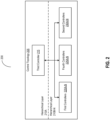
- the system 200 can include at least one control topology 205.
- the control topology 205 can identify or include a set of hierarchical layers 210A-N (hereinafter generally referred to as layers 210, or levels).
- the system 200 can include one or more controllers, such as at least one third controller 215 (sometimes herein referred to as a supervisory controller), a set of first controllers 220A-N (hereinafter generally referred to as a first controller 220, and sometimes referred herein as a first energy source controller and/or a fuel cell stack controller), a set of fourth controllers 225A-N (hereinafter generally referred to as a fourth controller 225, and sometimes referred herein as fuel cell engine controllers), and a set of second controllers 230A-N (hereinafter generally referred to as second controller 230, and sometimes herein referred to as a second energy source controller, battery controllers, and/or battery managers), among others.
- a third controller 215 sometimes herein referred to as a supervisory controller
- first controller 220A-N hereinafter generally referred to as a first controller 220, and sometimes referred herein as a first energy source controller and/or a fuel cell stack controller
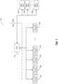
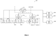
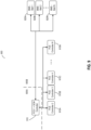
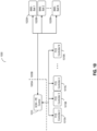
- the controllers can be arranged across the set of hierarchical layers 210, such as in accordance with the topologies as detailed herein in conjunction with FIGs. 6-10 .
- the controllers can be used to implement any one or more of the functionalities of the third controller 215, the first controllers 220, the fourth controllers 225, and the second controllers 230, among others.
- one controller may be embedded with the third controller 215 and the first controller 220 to carry out the functionalities of these controllers.
- the system 200 is configured to control operation of one or more components and/or subsystems of a diesel hybrid vehicle.
- the system 200 is configured to control operation of one or more components and/or subsystems of a fuel cell-based vehicle.
- the hierarchical structure of the control topology 205 can allow for the system 200 to be implemented on various types of powertrains, such as to facilitate abstraction of energy source control techniques using the first controllers 220 and second controllers 230 and allowing the third controller 215 to manage higher level functionality.
- the system 200 may include a plurality of first controllers 220 arranged in a second hierarchical layer 210B of the control topology 205.
- Each of the plurality of first controllers 220 can control a first source of energy (e.g., a fuel cell stack) of the vehicle 100.
- Each of the plurality of first controllers 220 can manage a respective fuel cell stack of a plurality of fuel cell stacks.
- Each of the plurality of fuel cell stacks can provide electrical energy to a component in the vehicle.
- each of the plurality of first controllers 220 can control the first source of energy of the vehicle 100 based on data of the first source of energy.
- the first controllers 220 can provide a first signal directly to the first source of energy based on the data of the first source of energy.
- the system 200 may include a plurality of second controllers 230 arranged in the second hierarchical layer 210B of the control topology 205.
- Each of the plurality of second controllers 230 can control a second source of energy (e.g., a battery) of the vehicle 100.
- the second controllers 230 can provide a second signal directly to the second source of energy based on the data of the second source of energy.
- the plurality of second controllers 230 can be coupled with a plurality of battery packs disposed in the vehicle 100.
- Each of the plurality second controllers 230 can manage a respective battery pack of the plurality of battery packs. In some embodiments, each of the plurality of second controllers 230 can control the second source of energy of the vehicle 100 based on data of the second source of energy.
- the system can include a third controller 215 coupled with the first plurality of controllers 220 and the second plurality of controllers 230.
- the third controller 215 can be arranged in a first hierarchical layer 210A of the control topology 205.
- the third controller 215 can interface with: (i) one or more of the plurality of first controllers 220 and the plurality of second controllers 230 and (ii) the vehicle powertrain configured to control propulsion of the vehicle.
- the third controller 215 can receive the data of the first source of energy and/or the data of the second source of energy. For example, the third controller 215 can receive the data from the second hierarchical layer 210B. In some embodiments, the third controller 215 can generate a control signal based on the data (e.g., of the first source of energy and/or of the second source of energy). In some embodiments, the third controller 215 can transmit the control signal to a component of the vehicle 100 to control the component of the vehicle 100. In some embodiments, the component of the vehicle 100 can include a sub-component of a powertrain of the vehicle 100. The third controller 215 can generate the control signal to control the sub-component of the power train of the vehicle 100.
- the component of the vehicle 100 can include a propulsion component of the vehicle, a navigation component of the vehicle, a power electronics, a converter, or a high-voltage component of the vehicle.
- the third controller can generate the control signal to control one of propulsion of the vehicle, navigation of the vehicle, the power electronics, the converter, or the high-voltage component of the vehicle.
- the component of the vehicle 100 can include an internal electrical energy source of the vehicle 100.
- the third controller 215 can generate the control signal to control the internal electrical energy source of the vehicle 100.
- the first source of energy includes a fuel cell stack.
- the first controller 220 can control the fuel cell stack.
- the second source of energy includes a battery pack.
- the second controller 230 can control the battery pack.
- the third controller 215 can be a supervisory controller configured to generate the control signal based on the data of the first source of energy (e.g., the fuel cell stack) and/or the data of the second source of energy (e.g., the battery pack).
- the system 200 can include the plurality of fourth controllers 225 arranged in a third hierarchical layer 215C of the control topology 205.
- Each of the plurality of fourth controllers 225 can (i) regulate at least one of an electrical control and a thermal manager for at least one of the plurality of fuel cell stacks and (ii) control one or more of the plurality of first controllers 220 arranged in the second hierarchical layer 210B.
- the third controller 215 can indirectly interface with one or more of the plurality of first controllers 220 via at least one of the plurality of fourth controllers 225.
- each of the plurality of first controllers 220 can regulate an electrical control and a thermal manager for at least one of the plurality of fuel cell stacks.
- the system 200 can include at least one fourth controller 225 arranged in a third hierarchical layer 215C of the control topology 205.
- the at least one fourth controller 225 can (i) regulate at least one of an electrical control and a thermal manager for at least one of the plurality of fuel cell stacks and (ii) control at least one first controller of the plurality of first controllers 220 arranged in the second hierarchical layer 210B.
- the third controller 215 can indirectly interface with the at least one first controller 220 via the at least one fourth controller 225.
- the third controller 215 can directly interface with at least one other first controller of the plurality of first controllers 220.
- the third controller 215 can regulate an electrical control and a thermal manager for at least one of the plurality of fuel cell stacks associated with the at least one other first controller 220.
- each of the plurality of first controllers 220 can regulate an electrical control and a thermal manager for at least one of the plurality of fuel cell stacks.
- the third controller 215 can: (i) manage the respective fuel cell stack of the plurality of fuel cell stacks and (ii) regulate, via interfacing with at least one of the plurality of first controllers 220, the electrical control and the thermal manager for at least one of the plurality of fuel cell stacks.
- the third controller 215 can control a power electronics to operate the plurality of battery packs and a propulsion component for the propulsion of the vehicle.
- the first controllers 220 in controlling the propulsion of the vehicle 100, can control generation or conveyance of electrical power from one of the plurality of fuel cell stacks.
- the first hierarchical layer 210A is higher in the control topology 205 than the second hierarchical layer 210B.
- At least one controller in the second hierarchical layer 210B can provide data (e.g., sensor data, data of the first source of energy, data of the second source of energy, etc.) to the third controller 215.
- the third controller 215 can generate a control signal based on the data.
- the first hierarchical layer 210A can be a system level layer configured to supervise the second hierarchical layer 210B.
- the third controller 215 can be a supervisory controller configured to control functions related to the first controller 220 and/or the second controller 230.
- the second hierarchical layer 210B can be an engine level layer or a module level layer associated with operation of the vehicle 100.
- the control topology 205 (e.g., including the layers 210, the third controller 215, the first controllers 220, the fourth controllers 225, and the second controllers 230) and the system 200 can be implemented using circuitry, such as one or more processors coupled with memory, such as those in the ECU 105 of the vehicle 100.
- the circuitry can include logic or machine-readable instructions to define the behavior, functions, and operations of the circuitry.
- the functions attributed or defined by the machine-readable instructions can be attributable to the circuitry overall.
- the circuitry can be implemented by computer readable media which can include code written in any programming language, including, but not limited to, Java, JavaScript, Python or the like and any conventional procedural programming languages, such as the "C" programming language or similar programming languages.
- the machine-readable instructions can be stored and maintained on memory.
- the circuitry can include one or more processors to execute the machine-readable instructions.
- the one or more processors can be coupled with the memory to execute the machine-readable instructions therefrom.
- the processor can be implemented as a single- or multi-chip processor, a digital signal processor (DSP), an application specific integrated circuit (ASIC), a field programmable gate array (FPGA), or other programmable logic device, discrete gate or transistor logic, discrete hardware components, or any combination thereof designed to perform the functions described herein.
- a processor may be a microprocessor, or any conventional processor, or state machine.
- the processor also may be implemented as a combination of computing devices, such as a combination of a digital signal processor (DSP) and a microprocessor, a plurality of microprocessors, one or more microprocessors in conjunction with a DSP core, or any other such configuration.
- the one or more processors may be shared by multiple circuits may comprise or otherwise share the same processor which, in some example embodiments, may execute instructions stored, or otherwise accessed, via different areas of memory.
- the one or more processors may be structured to perform or otherwise execute certain operations independent of one or more co-processors.
- two or more processors may be coupled via a bus to enable independent, parallel, pipelined, or multi-threaded instruction execution.
- the memory may include one or more devices (e.g., RAM, ROM, Flash memory, hard disk storage) for storing data and/or computer code for completing or facilitating the various processes, layers and modules described in the present disclosure.
- the memory may be communicably connected to the processor to provide computer code or instructions to the processor for executing at least some of the processes described herein.
- the memory may be or include tangible, non-transient volatile memory or non-volatile memory. Accordingly, the memory may include database components, object code components, script components, or any other type of information structure for supporting the various activities and information structures described herein.
- the third controller 215 can be situated, deployed, or otherwise arranged in a first hierarchical layer 210A (sometimes referred herein as a system layer or system level) of the set of layers 210 in the control topology 205.
- the third controller 215 can be coupled with the set of first controllers 220, the set of fourth controllers 225, or the set of second controllers 230, among others.
- the third controller 215 can interface with one or more of: the set of first controllers 220, the set of fourth controllers 225, or the set of second controllers 230, among other.
- the third controller 215 can communicate data with the controllers in the other hierarchical layers 210B-N of the control topology 205.
- the third controller 215 can relay, convey, or otherwise send control signals to the other controllers.
- the third controller 215 can accept, obtain, or otherwise receive feedback and sensor data from the other controllers.
- the third controller 215 can interface with at least one controller in one hierarchical layer 210 (e.g., the third hierarchical layer 210C) indirectly via at least one other controller in another hierarchical layer 210 (e.g., the second hierarchical layer 210B).
- the third controller 215 can directly interface with at least one controller in another hierarchical layer 210 (e.g., the second hierarchical layer 210B).
- the third controller 215 can also interface with a vehicle powertrain (e.g., the fuel tank 110, the battery pack 120, the power converter 125, the electric traction motor 130, the transmission 135, and the thermal system 145) to control propulsion or navigation of the vehicle 100.
- a vehicle powertrain e.g., the fuel tank 110, the battery pack 120, the power converter 125, the electric traction motor 130, the transmission 135, and the thermal system 145.
- the third controller 215 can interface with components of the vehicle powertrain indirectly (e.g., through one of the other controllers).
- the third controller 215 can directly interface with the components of the vehicle powertrain.
- the third controller 215 can data with the vehicle powertrain.
- the third controller 215 can accept, obtain, or otherwise receive feedback and sensor data from the vehicle powertrain.
- the third controller 215 can relay, convey, or otherwise send control signals to the vehicle powertrain.
- the third controller 215 can administer, handle, or otherwise control a power electronics (e.g., the power converter 125) to operate one or more battery packs (e.g., the battery pack 120) and at least one electric traction motor (e.g., the electric traction motor 130) in the vehicle 100.
- the power electronics may be a part of the vehicle powertrain or a component separate from the vehicle powertrain.
- the third controller 215 can interface with components of the power electronics indirectly (e.g., through one of the other controllers). In some embodiments, the third controller 215 can directly interface with the power electronics. By interfacing, the third controller 215 can data with the power electronics.
- the third controller 215 can accept, obtain, or otherwise receive feedback and sensor data from the other power electronics. Using the data, the third controller 215 can calculate, determine, or otherwise generate controls to be applied or provided. The third controller 215 can relay, convey, or otherwise send control signals to the vehicle power electronics.
- the set of first controllers 220 (sometimes referred herein fuel cell power module (FCPM) controllers) can be situated, deployed, or otherwise arranged in another hierarchical layer 210B-N (sometimes herein referred as a module layer or a module level) in the control topology 205.
- the hierarchical layer 210B-N in which the set of first controllers 220 is arranged can correspond to a layer or level below the first hierarchical layer 210A in which the third controller 215 is arranged.
- Each first controller 220 can handle, administer, or other manage at least one respective fuel cell stack (e.g., the fuel cell stack 115) to convey, relay, or otherwise provide electrical energy to other components in the vehicle 100.
- the first controller 220 can interface with the respective fuel cell stack.
- the first controller 220 can accept, obtain, or otherwise receive feedback and sensor data from the fuel cell stack 115. Using the data, the first controller 220 can calculate, determine, or otherwise generate controls to be applied or provided. The first controller 220 can relay, convey, or otherwise send control signals to the fuel cell stack 115.
- the set of fourth controllers 225 can be situated, deployed, or otherwise arranged in another hierarchical layer 210B-N (sometimes herein referred as an engine layer or an engine level) in the control topology 205.
- the hierarchical layer 210B-N in which the set of first controllers 220 is arranged can correspond to a layer or level below the first hierarchical layer 210A in which the third controller 215 is arranged.
- Each fourth controller 225 can handle, manage, or otherwise regulate an electronic control (e.g., power converter 125) or a thermal manager (e.g., the thermal system 145) for one or more fuel cell stacks (e.g., the fuel cell stack 115) in the vehicle 100.
- the fourth controller 225 can obtain, accept, or otherwise receive sensor data and feedback from the electronic control and the thermal manager. Using the data, the fourth controller 225 can calculate, determine, or otherwise generate controls to be applied or provided. The fourth controller 225 can convey, relay, or otherwise send the control signals to the electronic control and the thermal manager. The fourth controller 225 can handle, manage, or otherwise control another controller in another hierarchical layer 210, such as at least one of the first controllers 220.
- the set of second controllers 230 can be situated, deployed, or otherwise arranged in another hierarchical layer 210B-N (sometimes herein referred as a module layer or a module level) in the control topology 205.
- the hierarchical layer 210B-N in which the set of first controllers 220 is arranged can correspond to a layer or level below the first hierarchical layer 210A in which the third controller 215 is arranged.
- Each second controller 230 can handle, administer, or otherwise manage at least one respective battery pack (e.g., the battery pack 120) in the vehicle 100.
- the second controller 230 can obtain, accept, or otherwise receive sensor data and feedback from the battery pack. Using the data, the second controller 230 can calculate, determine, or otherwise generate controls to be applied or provided.
- the second controller 230 can convey, relay, or otherwise send control signals to the battery pack.
- the architecture 300 (sometimes referred herein as a system level architecture) can include the third controller 215 and at least one vehicle powertrain 305.
- the architecture 300 can be arranged in at least one of the hierarchical layers 210 (e.g., the top hierarchical layer 210A) of the control topology 205 for the vehicle 100.
- the vehicle powertrain 305 can correspond to or include at least one fuel cell engine 310, at least one battery pack 315, at least one fuel storage 320, at least one thermal manager 325, a set of propulsion components 330A-N (hereinafter generally referred herein as propulsion components 330), and at least one power electronics 335, among others.
- the third controller 215 can handle, manage, or otherwise control one or more control components of the vehicle powertrain 305.
- the third controller 215 can interface the vehicle powertrain 305 (e.g., the components) to control propulsion or navigation of the vehicle 100. In interfacing, the third controller 215 can retrieve, identify, or otherwise receive data (e.g., sensor data and feedback) from the components of the vehicle powertrain 305.
- the third controller 215 can relay, convey, or otherwise send data (e.g., a control signal) to the components of the vehicle powertrain 305.
- the components of the vehicle powertrain 305 can be instance of the components detailed herein above in conjunction with FIG. 1 .
- the fuel cell engine 310 can correspond to or include one or more components to administer, handle, or otherwise control one or more fuel cell stacks (e.g., instances of the fuel cell stack 115).
- the one or more components can be part of the vehicle 100 and at least partially implemented using circuitry (e.g., the ECU 105 as discussed above or elsewhere) in the vehicle 100.
- the fuel cell engine 310 can be coupled with the third controller 215 to interface and communicate with the third controller 215. In interfacing, the fuel cell engine 310 can convey, relay, or otherwise send sensor data and feedback data to the third controller 215.
- the fuel cell engine 310 can also retrieve, identify, or otherwise receive control signals from the third controller 215, or other controllers. Additional details regarding the fuel cell engine 310 are provided herein below in conjunction with FIG. 4 .
- the battery pack 315 can contain, house, or include a set of battery cells to store and maintain electrical power to provide to other components electrically coupled therewith in the vehicle 100.
- the battery pack 315 can be an instance of the battery pack 120 as discussed above.
- the battery pack 315 can be coupled with the third controller 215 to interface and communicate with the third controller 215. In interfacing, the battery pack 315 can convey, relay, or otherwise send sensor data and feedback data to the third controller 215.
- the data from the battery pack 315 can include, for example: a temperature; coolant temperature; state of charge; voltage output; power output; and internal pressure, among others.
- the battery pack 315 can also retrieve, identify, or otherwise receive control signals from the third controller 215, or other controllers.
- the control signals can include, for example: a command to set or adjust (e.g., increase or decrease) output power; a command to modify coolant flow; or a command to enable or disable (e.g., turning on and off) battery cells within the battery pack 315, among others.
- the fuel storage 320 can store, house, or otherwise contain hydrogen fuel to be converted to electrical power for the various components in the vehicle 100.
- the fuel storage 320 can be an instance of the fuel storage 320 as discussed above.
- the fuel storage 320 can be coupled with the third controller 215 to interface and communicate with the third controller 215. In interfacing, the fuel storage 320 can convey, relay, or otherwise send sensor data and feedback data to the third controller 215.
- the data from the fuel storage 320 can include, for example: hydrogen pressure; temperature; volume; flow rate; valve status; and weight, among others.
- the fuel storage 320 can also retrieve, identify, or otherwise receive control signals from the third controller 215, or other controllers.
- the control signals can include, for example: a command to set or adjust (e.g., increase or decrease) hydrogen flow rate; a command to change temperature; and a command to enable or disable (e.g., turn on or shut down) the fuel storage 320, among others.
- the thermal manager 325 can handle, regulate, or otherwise maintain a temperature of various components in the vehicle 100 within a target range of temperatures for each respective component.
- the thermal manager 325 can be an instance of the thermal system 145 as discussed above.
- the thermal manager 325 can be coupled with the third controller 215 to interface and communicate with the third controller 215. In interfacing, the thermal manager 325 can convey, relay, or otherwise send sensor data and feedback data to the third controller 215.
- the data from the thermal manager 325 can include, for example: a temperature of various components in the vehicle 100 (e.g., the fuel cell stack 115, the battery pack 120, and the transmission 135); a temperature of the coolant; a coolant flow rate; and a status of heat exchangers, radiators, and fans, among others.
- the thermal manager 325 can also retrieve, identify, or otherwise receive control signals from the third controller 215, or other controllers.
- the control signals can include, for example: a command to change (e.g., increase or decrease) coolant flow rate; a command to enable or disable (e.g., activate or deactivate) heat exchanges, radiators, fans, or coolant flow; or a command to enable or disable components (e.g., at least a portion of the fuel cell stack 115 or the battery pack 315) in the vehicle 100, among others.
- the set of propulsion component 330 can one or more components to convert electrical power to mechanical power to control propulsion or navigation of the vehicle 100 through the environment.
- the propulsion components 330 can include instances of the power converter 125, the electric traction motor 130, the transmission 135, and the wheels 140, among others, as discussed above.
- Each of the propulsion components 330 can be coupled with the third controller 215 to interface and communicate with the third controller 215. In interfacing, each propulsion components330 can convey, relay, or otherwise send sensor data and feedback data to the third controller 215.
- the data from the propulsion component 330 can include, for example: a speed, a temperature, a torque, and power from the electric traction motor 130; a gear ratio, a shift position, a fluid temperature, a rotation speed from the transmission 135; a speed of driveshaft; a wheel speed; an axle temperature; a differential temperature; vibration; suspension measurements; brake usage; and torque distribution, among others.
- the propulsion component 330 can also retrieve, identify, or otherwise receive control signals from the third controller 215, or other controllers.
- the control signals can include, for example: a command for gear selection; a command to shift gears; a command to control torque in the motor; a command to set power output; a command for regenerative braking; a command for braking system; and a command for suspension control; among others.
- the power electronics 335 can administer, configure, or otherwise manage a distribution of electrical power throughout the components in the vehicle 100.
- the components of the power electronics 335 can be situated, arranged, or otherwise disposed in an interior portion of the vehicle 100.
- the power electronics 335 can include an instance of the power converter 125 as discussed above.
- the controls for the power electronics 335 can be a part of the third controller 215.
- the power electronics 335 can be coupled with the third controller 215 to interface and communicate with the third controller 215. In interfacing, the power electronics 335 can convey, relay, or otherwise send sensor data and feedback data to the third controller 215.
- the data from the power electronics 335 can include, for example: a measurement of voltage, a measurement of current, or a measurement of power over time at each component in the vehicle 100, among others.
- the power electronics 335 can also retrieve, identify, or otherwise receive control signals from the third controller 215, or other controllers.
- the control signals can include, for example: a command to set or adjust (e.g., increase or decrease) voltage, current, or power at each component; and a command to configure distribution of voltage, current, or power among the components in the vehicle 100, among others.
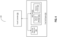
- the architecture 400 (sometimes referred herein as an engine level architecture) can include the fourth controller 225 and the fuel cell engine 310.
- the architecture 400 can be arranged in at least one of the hierarchical layers 210 of the control topology 205 for the vehicle 100.
- the fuel cell engine 310 can include at least one fuel cell stack unit 405 and at least one balance of plant (BoP) unit 410, among others.
- the BoP unit 410 can include at least one fuel cell thermal manager 415 (sometimes herein referred toas a fuel cell thermal management system or FC-TMS) and at least one electrical control 420 (sometimes referred herein as an electrical module), among others.
- the fuel cell engine 310 can include a single instance of the fuel cell stack unit 405 (e.g., as depicted) or multiple instances of the fuel cell stack unit 405.
- the fuel cell engine 310 can be at least partially implemented using circuitry (e.g., the ECU 105 as discussed above or elsewhere) in the vehicle 100.
- the fuel cell stack unit 405 can correspond to or include one or more components to administer, handle, or otherwise control fuel cell stack (e.g., the fuel cell stack 115) and related components (e.g., the fuel tank 110 or fuel storage 320).
- the one or more components of the fuel cell stack unit 405 can be part of the vehicle 100 and at least partially implemented using circuitry (e.g., the ECU 105 as discussed above or elsewhere) in the vehicle 100.
- the fuel cell stack unit 405 can be coupled with the fourth controller 225 to interface and communicate with the fourth controller 225. In interfacing, the fuel cell stack unit 405 can convey, relay, or otherwise send sensor data and feedback data to the fourth controller 225.
- the fuel cell stack unit 405 can also retrieve, identify, or otherwise receive control signals from the fourth controller 225, or other controllers. Additional details regarding the fuel cell stack unit 405 are provided herein below in conjunction with FIG. 5 .
- the BoP unit 410 can correspond to or include one or more components to administer, control, or otherwise regulate various operations of the fuel cell stack (e.g., the fuel cell stack 115) in the vehicle 100.
- the one or more components of the BoP unit 410 and the components therein can be part of the vehicle 100 and at least partially implemented using circuitry (e.g., the ECU 105 as discussed above or elsewhere) in the vehicle 100.
- the BoP unit 410 can be coupled with the fourth controller 225 to interface and communicate with the fourth controller 225.
- the fuel cell stack unit 405 can convey, relay, or otherwise send sensor data and feedback data to the fourth controller 225.
- the fourth controller 225 can calculate, determine, or otherwise generate control signals to be applied or provided.
- the fuel cell stack unit 405 can also retrieve, identify, or otherwise receive control signals from the fourth controller 225, or other controllers. Via the BoP unit 410, the fourth controller 225 can control or regulate at least one of the fuel cell thermal manager 415 or the electrical control 420.
- the fuel cell thermal manager 415 can administer, regulate, or otherwise control temperature of at least one respective fuel cell stack (e.g., an instance of the fuel cell stack 115).
- the fuel cell thermal manager 415 can be coupled with one or more components to perform or carry out regulation of the temperature.
- the components coupled with the fuel cell thermal manager 415 can include, for example: a pump for coolant flow; a valve (e.g., three-way valve) to direct coolant flow; a deionization (DI) polisher to remove ions from the coolant provided to the fuel cell stack; an electric heater to apply heat to the fuel cell stack; a ventilation fan to cool the fuel cell stack via air circulation; and a strainer to remove contaminants and other particles from the coolant, among others.
- the fuel cell thermal manager 415 can be an instance of the thermal system 145, a part of the thermal system 145, or
- the fuel cell thermal manager 415 can be coupled with the fourth controller 225 to interface and communicate with the fourth controller 225.
- the fuel cell thermal manager 415 can relay, convey, or otherwise provide sensor data or feedback data to the fourth controller 225.
- the data can include, for example: a temperature of fuel cell stack; coolant flow rate; coolant temperature; density of contaminants the coolant; temperature of heater; a status of the fuel cell stack; and a status of each component, among others.
- the fuel cell thermal manager 415 can retrieve, identify, or otherwise receive control signals from the fourth controller 225.
- the control signals can include, for example: a command to direct coolant flow; a command to set or adjust (e.g., increase or decrease) coolant flow rate; and a command to enable or disable a respective component; among others.
- the control signals may have been generated by the fourth controller 225 using the data relayed by the fuel cell thermal manager 415.
- the fourth controller 225 can determine to increase rate of coolant flow when the temperature of the fuel cell stack exceeds a threshold level.
- the fuel cell thermal manager 415 can pass, forward, or otherwise provide the control signals from the fourth controller 225 to the components.
- the electrical control 420 can administer, handle, or otherwise control conveyance of electrical power between at least one respective fuel cell stack (e.g., an instance of the fuel cell stack 115) and various components in the vehicle 100 (e.g., the vehicle powertrain 305).
- the fuel cell stack controlled by the electrical control 420 can be the same as fuel cell stack managed by the fuel cell thermal manager 415.
- the fuel cell stack can be coupled with one or more components to perform or carry out the controlling of the conveyance of the electrical power.
- the components coupled with the electrical control 420 can include, for example: an engine control unit; a DC/DC converter; high voltage (HV) or low voltage (LV) bus connectors; one or more sensors (e.g., pressure gauge, thermometer, ampere meter, voltage meter, or power meter); and fuel cell junction box, among others.
- the engine control unit can handle, manage, or control various components of the vehicle powertrain 305, such as the power converter 125, the electric traction motor 130, the transmission 135, and the wheels 140 among others.
- the engine control unit can include one or more sensors to measure pedal position, vehicle speed, wheel speed, motor torque, and rotation speed of driveshaft, among others.
- the electrical control 420 can be coupled with the fourth controller 225 to interface and communicate with the fourth controller 225.
- the electrical control 420 can relay, convey, or otherwise provide sensor data or feedback data to the fourth controller 225.
- the data can include, for example: output power, voltage, or current from the fuel cell stack or the battery pack; converted power, voltage, or current at the converter; pressure in fuel cell stack; temperature of fuel cell stack; vehicle speed, acceleration, torque; pedal position; motor torque; and rotation speed, among others.
- the electrical control 420 can retrieve, identify, or otherwise receive control signals from the fourth controller 225.
- the control signals can include, for example: a command to set or adjust output power, voltage, or current from the fuel cell stack; a command to set or adjust converted power, voltage, or current; a command to distribute torque among the wheel, among others.
- the control signals may have been generated by the fourth controller 225 using the data relayed by the electrical control 420.
- the fourth controller 225 can detect a pedal position indicating a request for higher acceleration and generate a command signal to increase output power to effectuate the higher acceleration.
- the electrical control 420 can pass, forward, or otherwise provide the control signals from the fourth controller 225 to the components.
- the first controller (e.g., the first controller 220 of FIG. 2 ) can manage the respective fuel cell stack including the BoP mechanism 410 configured to manage heat, ventilation, or power distribution.
- the BoP mechanism 410 can include a thermal management system (e.g., the fuel cell thermal manager 415) and/or an electrical module (e.g., the electrical control 420).
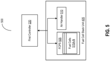
- the architecture 500 (sometimes referred herein as a module level architecture) can include the first controller 220 and the fuel cell stack unit 405.
- the architecture 500 can be arranged in at least one of the hierarchical layers 210 of the control topology 205 for the vehicle 100.
- the fuel cell stack unit 405 can include at least one fuel cell power stack (FCPS) 505, at least one air handler 510, and a set of fuel cells 515A-N (hereinafter generally referred to as fuel cells 515).
- FCPS fuel cell power stack
- the fuel cell stack unit 405 can be at least partially implemented using circuitry (e.g., the ECU 105 as discussed above or elsewhere) in the vehicle 100.
- the FCPS 505 (sometimes herein referred to as a fuel cell power module (FCPM)) can correspond to or include one or more components to administer, manage, or otherwise control one or more respective fuel cells 515 in the vehicle 100.
- the FCPS 505 can correspond to a self-contained unit including various components to produce, regulate, and control conveyance of electrical power generated using the hydrogen fuel.
- the FCPS 505 can include the set of fuel cells 515 corresponding to a respective fuel cell stack (e.g., an instance of the fuel cell stack 115) or individual fuel cells in the fuel cell stack.
- Each fuel cell 515 can transform or convert the hydrogen fuel from the fuel storage (e.g., the fuel tank 110 or fuel storage 320) to produce electrical power, in the manner as previously described with respect to the fuel cell stack 115.
- the FCPS 505 can include one or more components to manage, regulate, or otherwise control generation and conveyance of electrical power from the fuel cells 515.
- the components can include, for example: a manifold to supply hydrogen fuel from the fuel storage to the fuel cells 515; a pump to pull the hydrogen fuel from the fuel storage; and a regulator to control flow rate of the hydrogen fuel; among others.
- the FCPS 505 can be coupled with the first controller 220 to interface and communicate with the first controller 220. In interfacing, the FCPS 505 can convey, relay, or otherwise send sensor data and feedback data to the first controller 220.
- the data can include, for example: flow rate of the hydrogen fuel, a temperature of the hydrogen fuel, a temperature of the fuel cells 515, a temperature of the manifold, a pump rate, among others.
- the first controller 220 can calculate, determine, or otherwise generate control signals to be applied or provided. For example, upon detecting a drop in a flow rate of the hydrogen below a tolerance range, the first controller 220 can generate a control signal to the pump to pull the hydrogen fuel at a higher rate from the fuel storage.
- the FCPS 505 can also retrieve, identify, or otherwise receive control signals from the first controller 220, or other controllers.
- the air handler 510 can one or more components to manage, regulate, or otherwise control flow of air into the fuel cells 515 of the FCPS 505 in the fuel cell stack unit 405.
- the components can include, for example: air plumbing to facilitate conveyance of air (e.g., oxygen (O 2 )) in the fuel cells 515 (e.g., in the cathode of each fuel cell 515); an air supplier to provide the air; an air compressor to control pressure of the air flowing into the fuel cells 515; a filter to remove or restrict particulates in the air; an air flow sensor to measure flow of air into or out of the fuel cells 515; and a value to enable, disable, or regulate flow of air into the fuel cells 515; among others.
- air plumbing to facilitate conveyance of air (e.g., oxygen (O 2 )) in the fuel cells 515 (e.g., in the cathode of each fuel cell 515); an air supplier to provide the air; an air compressor to control pressure of the air flowing into the fuel cells 515;
- the air handler 510 can be coupled with the first controller 220 to interface and communicate with the first controller 220. In interfacing, the air handler 510 can convey, relay, or otherwise send sensor data and feedback data to the first controller 220.
- the data can include, for example: a rate of air flow into the individual fuel cells 515; a rate of air flow out of the individual fuel cells 515; a pressure measurement of the air; a density of particulates; an amount of air; among others.
- the first controller 220 can calculate, determine, or otherwise generate control signals to be applied or provided.
- the first controller 220 can output a control signal for the compressor to increase compression of the air flowing into the fuel cells 551.
- the air handler 510 can also retrieve, identify, or otherwise receive control signals from the first controller 220, or other controllers.
- the arrangement 600 of the control topology 205 can include controllers, such as at least one supervisory controller (SCM) 610, a set of fuel cell engine (FCE) controllers 615A-N (hereinafter generally referred to as FCE controllers 615), a set of battery management systems (BMS) 620A-N (hereinafter generally referred to as BMS 620), and a set of fuel cell stack (FCS) controllers 625A to 2N (hereinafter generally referred to as FCS controllers 625), among others.
- SCM supervisory controller
- FCE controllers 615A-N hereinafter generally referred to as FCE controllers 615
- BMS battery management systems
- FCS controllers 625 a set of fuel cell stack controllers 625A to 2N
- the controllers can be arranged across at least one system layer 605A, at least one engine layer 605B, and at least one module layer 605C of the control topology 205, among others.
- the arrangement 600 for the control topology 205 can be implemented with circuitry implemented using circuitry (e.g., the ECU 105 as discussed above or elsewhere) in the vehicle 100.
- the SCM 610 can be arranged in the system layer 605A of the control topology 205.
- the SCM 610 can be an instance of the third controller 215 as discussed above.
- the SCM 610 can be coupled with other controllers, such as the set of FCE controllers 615, the set of BMSs 620, and the set of FCS controllers 625, among others.
- the SCM 610 can be directly coupled with the set of FCE controllers 615 and the set of BMSs 620 arranged on the engine layer 605B.
- the SCM 610 can interface with one or more of the set of FCE controllers 615 and the set of BMSs 620.
- the SCM 610 can be indirectly coupled with the set of FCS controllers 625 via the set of FCE controllers 615 arranged on the module layer 605C.
- the SCM 610 can interface with one or more of the set of FCS controllers 625 via one or more of the FCE controllers 615.
- the SCM 610 can also interface with a vehicle powertrain (e.g., the vehicle powertrain 305) to control propulsion of the vehicle.
- the set of FCE controllers 615 can be arranged in the engine layer 605B of the control topology 205 in the arrangement 600. Each FCE controller 615 can be an instance of the fourth controller 225 described above.
- the set of FCE controllers 615 can be coupled with the SCM 610 in the system layer 605A.
- the set of FCE controllers 615 can also be coupled with a respective subset of FCS controllers 625 in the module layer 605C.
- Each FCE controller 615 can manage, control, or otherwise regulate at least one of an electrical control (e.g., a respective instance of the electrical control 420) and a thermal manager (e.g., a respective instance of the fuel cell thermal manager 415) for at least one respective fuel cell stack (e.g., a respective instance of the fuel cell stack 115).
- Each FCE controller 615 can control the respective subset of FCS controllers 625.
- the arrangement 600 can include twice as many FCS controllers 625 as FCE controllers 615 and each FCE controller 615 can control at least two FCS controllers 625 (e.g., FCE controllers 625(2N-1) and 625(2N) in the module layer 605C.
- the set of BMSs 620 can be arranged in the engine layer 605B of the control topology 205 in the arrangement 600. In some embodiments, the set of BMSs 620 can be outside of the layers 605A-C of the control topology 205. Each BMS 620 can be an instance of the second controller 230 described above. The set of BMSs 620 can be coupled with the SCM 610 in the system layer 605A in the control topology 205. Each BMS 620 can administer, control, or otherwise manage a respective battery pack of a set of battery packs (e.g., a respective instance of the battery pack 120). In some embodiments, the functionalities of the set of BMSs 620 can be incorporated or embedded into the SCM 610 of the system layer 605A.
- the set of FCS controllers 625 can be arranged in the module layer 605C of the control topology 205 in the arrangement 600. Each FCS controller 625 can be an instance of the first controller 220 as described above. Each of FCS controllers 625 can be directly coupled with at least one of the FCE controllers 615 in the engine layer 605B. The set of FCS controllers 625 can also be indirectly coupled with the SCM 610 in the system layer 605A via at least one of the FCE controllers 615. Each FCS controller 625 can administer, handle, or otherwise control a respective fuel cell stack of a set of fuel cell stacks (e.g., instances of the fuel cell stack 115). Each fuel cell stack can provide electrical energy to components in the vehicle 100.
- the arrangement 700 of the control topology 205 can include controllers, such as at least one supervisory controller (SCM) 710, a set of fuel cell stack and fuel cell engine integrated (FCS-FCE) controllers 715A-N (hereinafter generally referred to as FCS-FCE controller 715), and a set of battery management systems (BMSs) 720A-N (hereinafter generally referred to as BMSs 720), among others.
- SCM supervisory controller
- FCS-FCE controller 715A-N hereinafter generally referred to as FCS-FCE controller 715
- BMSs battery management systems
- the controllers can be arranged across at least one system layer 705A and at least one module-engine integrated layer 705B, among others in the arrangement 700 for the control topology 205.
- the arrangement 700 for the control topology 205 can be implemented with circuitry implemented using circuitry (e.g., the ECU 105 as discussed above or elsewhere) in the vehicle 100.
- the SCM 710 can be arranged in the system layer 705A of the control topology 205.
- the SCM 710 can be an instance of the third controller 215 as discussed above.
- the SCM 710 can be coupled with other controllers, such as the set of FCS-FCE controllers 715 and the set of BMSs 720, among others.
- the SCM 710 can be directly coupled with the set of FCS-FCE controllers 715 and the set of BMSs 720 arranged on the engine-module layer 705B.
- the SCM 710 can interface with one or more of the set of FCS-FCE controllers 715 and the set of BMSs 720.
- the SCM 710 can interface with one or more of the set of FCS controllers 725 via one or more of the FCS-FCE controllers 715.
- the SCM 710 can also interface with a vehicle powertrain (e.g., the vehicle powertrain 305) to control propulsion of the vehicle.
- the set of FCS-FCE controllers 715 can be arranged in the engine-module layer 705B of the control topology 205 in the arrangement 700.
- Each FCS-FCE controller 715 can be an integrated instance of the first controller 220 and fourth controller 225 described above.
- the set of FCS-FCE controllers 715 can be coupled with the SCM 710 in the system layer 705A.
- Each FCS-FCE controller 715 can manage, control, or otherwise regulate at least one of an electrical control (e.g., a respective instance of the electrical control 420) and a thermal manager (e.g., a respective instance of the fuel cell thermal manager 415) for at least one respective fuel cell stack (e.g., a respective instance of the fuel cell stack 115).
- Each FCS-FCE controller 715 can also administer, handle, or otherwise control a respective fuel cell stack of a set of fuel cell stacks (e.g., instances of the fuel cell stack 115).
- Each fuel cell stack can provide electrical energy to components in
- the set of BMSs 720 can be arranged in the engine-module layer 705B of the control topology 205 in the arrangement 700. In some embodiments, the set of BMSs 720 can be outside of the layers 705A-C of the control topology 205. Each BMS 720 can be an instance of the second controller 230 described above. The set of BMSs 720 can be coupled with the SCM 710 in the system layer 705A in the control topology 205. Each BMS 720 can administer, control, or otherwise manage a respective battery pack of a set of battery packs (e.g., a respective instance of the battery pack 120). In some embodiments, the functionalities of the set of BMSs 720 can be incorporated or embedded into the SCM 710 of the system layer 705A.
- the arrangement 800 of the control topology 205 can include controllers, such as at least integrated one supervisory controller and fuel cell engine controller (FCE-SCM) 810, a set of fuel cell engine (FCE) controllers 815A-N (hereinafter generally referred to as FCE controllers 815), a set of battery managers (BMS) 820A-N (hereinafter generally referred to as BMS 820), and a set of fuel cell stack (FCS) controllers 825A to 2N (hereinafter generally referred to as FCS controllers 825), among others.
- FCE-SCM supervisory controller and fuel cell engine controller
- FCE controllers 815A-N hereinafter generally referred to as FCE controllers 815
- BMS battery managers
- FCS controllers 825 a set of fuel cell stack controllers 825A to 2N
- the controllers can be arranged across at least one system layer 805A, at least one engine layer 805B, and at least one module layer 805C of the control topology 205, among others.
- the arrangement 800 for the control topology 205 can be implemented with circuitry implemented using circuitry (e.g., the ECU 105 as discussed above or elsewhere) in the vehicle 100.
- the FCE-SCM 810 can be arranged in the system layer 805A of the control topology 205.
- the FCE-SCM 810 can be an integration of an instance of the third controller 215 with the fourth controller 225 as discussed above.
- the FCE-SCM 810 can be coupled with other controllers, such as the set of FCE controllers 815, the set of BMSs 820, and the set of FCS controllers 825, among others.
- the FCE-SCM 810 can be directly coupled with the set of FCE controllers 815 and the set of BMSs 820 arranged on the engine layer 805B and with a subset of FCS controllers 825 (e.g., the FCS controllers 825A and 825B) arranged on the module layer 805C.
- the FCE-SCM 810 can interface with one or more of the set of FCE controllers 815, the set of BMSs 820, and the subset of FCS controllers 825.
- the FCE-SCM 810 can provide system or supervisory control of the subset of FCS controllers 825.
- the FCE-SCM 810 can be indirectly coupled with a remaining subset of FCS controllers 825 via the set of FCE controllers 815 arranged on the module layer 805C.
- the FCE-SCM 810 can interface with one or more of the set of FCS controllers 825 via one or more of the FCE controllers 815.
- the FCE-SCM controller 810 can manage, control, or otherwise regulate at least one of an electrical control (e.g., a respective instance of the electrical control 420) and a thermal manager (e.g., a respective instance of the fuel cell thermal manager 415) for at least one respective fuel cell stack (e.g., a respective instance of the fuel cell stack 115).
- the FCE-SCM 810 can also interface with a vehicle powertrain (e.g., the vehicle powertrain 305) to control propulsion of the vehicle.
- the set of FCE controllers 815 can be arranged in the engine layer 805B of the control topology 205 in the arrangement 800. Each FCE controller 815 can be an instance of the fourth controller 225 described above.
- the set of FCE controllers 815 can be coupled with the FCE-SCM 810 in the system layer 805A.
- the set of FCE controllers 815 can also be coupled with a respective subset of FCS controllers 825 in the module layer 805C.
- Each FCE controller 815 can manage, control, or otherwise regulate at least one of an electrical control (e.g., a respective instance of the electrical control 420) and a thermal manager (e.g., a respective instance of the fuel cell thermal manager 415) for at least one respective fuel cell stack (e.g., a respective instance of the fuel cell stack 115).
- Each FCE controller 815 can control the respective subset of FCS controllers 825.
- the arrangement 800 can include at least twice as many FCS controllers 825 as FCE controllers 815 and each FCE controller 815 can control at least two FCS controllers 825 (e.g., FCS controllers 825(2N-1) and 825(2N) in the module layer 805C.
- the set of BMSs 820 can be arranged in the engine layer 805B of the control topology 205 in the arrangement 800. In some embodiments, the set of BMSs 820 can be outside of the layers 805A-C of the control topology 205. Each BMS 820 can be an instance of the second controller 230 described above. The set of BMSs 820 can be coupled with the FCE-SCM 810 in the system layer 805A in the control topology 205. Each BMS 820 can administer, control, or otherwise manage a respective battery pack of a set of battery packs (e.g., a respective instance of the battery pack 120). In some embodiments, the functionalities of the set of BMSs 820 can be incorporated or embedded into the FCE-SCM 810 of the system layer 805A.
- the set of FCS controllers 825 can be arranged in the module layer 805C of the control topology 205 in the arrangement 800. Each FCS controller 825 can be an instance of the first controller 220 as described above.
- a subset of FCS controllers 825 e.g., FCS controllers 825A and 825B
- FCS controllers 825A and 825B can be directly coupled with the FCE-SCM controller 810 in the system layer 805A.
- Each of a remaining subset FCS controllers 825 can be directly coupled with at least one of the FCE controllers 815 in the engine layer 805B.
- the set of FCS controllers 825 can also be indirectly coupled with the FCE-SCM 810 in the system layer 805A via at least one of the FCE controllers 815.
- Each FCS controller 825 can administer, handle, or otherwise control a respective fuel cell stack of a set of fuel cell stacks (e.g., instances of the fuel cell stack 115). Each fuel cell stack can provide electrical energy
- the arrangement 900 of the control topology 205 can include controllers, such as at least one integrated supervisory controller and fuel cell stack controller (FCS-SCM) 910, a set of fuel cell stack (FCS) controllers 915A-N (hereinafter generally referred to as FCS controllers 915), a set of battery manager systems (BMSs) 920A-N (hereinafter generally referred to as BMS 920), among others.
- FCS-SCM integrated supervisory controller and fuel cell stack controller
- FCS controllers 915A-N hereinafter generally referred to as FCS controllers 915
- BMSs battery manager systems
- the controllers can be arranged across at least one system layer 905A and at least one module layer 905B of the control topology 205, among others.
- the arrangement 900 for the control topology 205 can be implemented with circuitry implemented using circuitry (e.g., the ECU 105 as discussed above or elsewhere) in the vehicle 100.
- the FCS-SCM 910 can be arranged in the system layer 905A of the control topology 205.
- the FCS-SCM 910 can be an instance of the third controller 215 integrated with an instance of the first controller 220 as discussed above.
- the FCS-SCM 910 can be coupled with other controllers, such as the set of FCS controllers 915 and the set of BMSs 920 among others.
- the FCS-SCM 910 can be directly coupled with the set of FCS controllers 915 and the set of BMSs 920 arranged on the module layer 905B.
- the FCS-SCM 910 can interface with one or more of the set of FCS controllers 915 and the set of BMSs 920.
- the FCS-SCM 910 can also interface with a vehicle powertrain (e.g., the vehicle powertrain 305) to control propulsion of the vehicle.
- the FCS-SCM 910 can provide system level supervisory control of functions related to the first controller 220 and the fourth controller 225 as discussed above.
- the FCS-SCM 910 can also manage, control, or otherwise regulate at least one of an electrical control (e.g., a respective instance of the electrical control 420) and a thermal manager (e.g., a respective instance of the fuel cell thermal manager 415) for at least one respective fuel cell stack (e.g., a respective instance of the fuel cell stack 115).
- the FCS-SCM 910 can administer, handle, or otherwise control a respective fuel cell stack of a set of fuel cell stacks (e.g., instances of the fuel cell stack 115). Each fuel cell stack can provide electrical energy to components in the vehicle 100.
- the set of BMSs 920 can be arranged in the module layer 905B of the control topology 205 in the arrangement 900. In some embodiments, the set of BMSs 920 can be outside of the layers 905A-C of the control topology 205. Each BMS 920 can be an instance of the second controller 230 described above. The set of BMSs 920 can be coupled with the FCS-SCM 910 in the system layer 905A in the control topology 205. Each BMS 920 can administer, control, or otherwise manage a respective battery pack of a set of battery packs (e.g., a respective instance of the battery pack 120). In some embodiments, the functionalities of the set of BMSs 920 can be incorporated or embedded into the FCS-SCM 910 of the system layer 905A.
- the set of FCS controllers 915 can be arranged in the module layer 905C of the control topology 205 in the arrangement 900.
- Each FCS controller 915 can be an instance of the first controller 220 as described above.
- Each of FCS controllers 915 can be directly coupled with the FCS-SCM controller 910 in the system layer 905 of the control topology 205.
- Each FCS controller 915 can administer, handle, or otherwise control a respective fuel cell stack of a set of fuel cell stacks (e.g., instances of the fuel cell stack 115).
- Each fuel cell stack can provide electrical energy to components in the vehicle 100.
- the arrangement 1000 of the control topology 205 can include controllers, such as at least one integrated supervisory controller and power electronics controller (PE-SCM) 1010, a set of fuel cell stack (FCS) controllers 1015A-N (hereinafter generally referred to as FCS controllers 1015), a set of battery manager systems (BMSs) 1020A-N (hereinafter generally referred to as BMS 1020), among others.
- PE-SCM integrated supervisory controller and power electronics controller
- FCS controllers 1015A-N hereinafter generally referred to as FCS controllers 1015
- BMSs battery manager systems
- the controllers can be arranged across at least one system layer 1005A and at least one module layer 1005B of the control topology 205, among others.
- the arrangement 1000 for the control topology 205 can be implemented with circuitry implemented using circuitry (e.g., the ECU 105 as discussed above or elsewhere) in the vehicle 100.
- the PE-SCM 1010 can be arranged in the system layer 1005A of the control topology 205.
- the PE-SCM 1010 can be an instance of the third controller 215 integrated with an instance of the power electronics 335 as discussed above.
- the PE-SCM 1010 can be coupled with other controllers, such as the set of FCS controllers 1015 and the set of BMSs 1020 among others.
- the PE-SCM 1010 can be directly coupled with the set of FCS controllers 1015 and the set of BMSs 1020 arranged on the module layer 1005B.
- the PE-SCM 1010 can interface with one or more of the set of FCS controllers 1015 and the set of BMSs 1020.
- the PE-SCM 1010 can also interface with a vehicle powertrain (e.g., the vehicle powertrain 305) to control propulsion of the vehicle.
- a vehicle powertrain e.g., the vehicle powertrain 305
- the PE-SCM 1010 can also administer, configure, or otherwise manage a distribution of electrical power throughout the components in the vehicle 100.
- the FE-SCM 1010 can control operations of battery packs and an electronic motor for the propulsion of the vehicle.
- the PE-SCM 1010 can also integrate functionalities of the first controller 220 or the fourth controller 225 as discussed above, or both.
- the PE-SCM 1010 can provide system level supervisory control of functions related to the first controller 220 and the fourth controller 225 as discussed above.
- the PE-SCM 1010 can also manage, control, or otherwise regulate at least one of an electrical control (e.g., a respective instance of the electrical control 420) and a thermal manager (e.g., a respective instance of the fuel cell thermal manager 415) for at least one respective fuel cell stack (e.g., a respective instance of the fuel cell stack 115).
- the PE-SCM 1010 can administer, handle, or otherwise control a respective fuel cell stack of a set of fuel cell stacks (e.g., instances of the fuel cell stack 115). Each fuel cell stack can provide electrical energy to components in the vehicle 100.
- the set of FCS controllers 1015 can be arranged in the module layer 1005C of the control topology 205 in the arrangement 1000.
- Each FCS controller 1015 can be an instance of the first controller 220 as described above.
- Each of FCS controllers 1015 can be directly coupled with the PE-SCM controller 1010 in the system layer 1005 of the control topology 205.
- Each FCS controller 1015 can administer, handle, or otherwise control a respective fuel cell stack of a set of fuel cell stacks (e.g., instances of the fuel cell stack 115). Each fuel cell stack can provide electrical energy to components in the vehicle 100.
- each FCS controller 1010 can be integrated with the functionalities of the fourth controller 225 described above.
- the set of BMSs 1020 can be arranged in the module layer 1005B of the control topology 205 in the arrangement 1000. In some embodiments, the set of BMSs 1020 can be outside of the layers 1005A-C of the control topology 205. Each BMS 1020 can be an instance of the second controller 230 described above. The set of BMSs 1020 can be coupled with the PE-SCM 1010 in the system layer 1005A in the control topology 205. Each BMS 1020 can administer, control, or otherwise manage a respective battery pack of a set of battery packs (e.g., a respective instance of the battery pack 120). In some embodiments, the functionalities of the set of BMSs 1020 can be incorporated or embedded into the PE-SCM 1010 of the system layer 1005A.
- FIG. 11 depicts a flow chart of an example method 1100 for vehicle power control in accordance with an illustrative embodiment. It is noted that the method 1100 is merely an example and is not intended to limit the present disclosure. Accordingly, it is understood that additional operations may be provided before, during, and after the method 1100 of FIG. 11 , and that some other operations may only be briefly described herein.
- the method 1100 begins with operation 1110 of identifying a first controller.
- the method 1100 may include identifying a plurality of first controllers in a first hierarchical layer of a control topology to control a first source of energy based on first data.
- the method 1100 continues to operation 1120 of identifying a second controller.
- the method 1100 may include identifying a plurality of second controllers in the first hierarchical layer to control a second source of energy based on second data.
- the method 1100 continues to operation 1130 of coupling a third controller.
- the method 1100 may include coupling a third controller with the plurality of first controllers and the plurality of second controllers.
- the method 1100 continues to operation 1140 of receiving data.
- the method 1100 may include receiving, by the third controller, the first data and the second data.
- the method 1100 continues to operation 1150 of generating a control signal.
- the method 1100 may include generating, by the third controller, a control signal based on the first data and the second data.
- the method 1100 continues to operation 1160 of transmitting the control signal.
- the method 1100 may include transmitting the control signal to a component to control the component.
- a plurality of first controllers can be arranged and/or identified in a first hierarchical layer (e.g., the hierarchical layer 210B) of a control topology (e.g., the control topology 205) to control a first source of energy based on first data.
- Each of the plurality of first controllers can control the first source of energy of a vehicle (e.g., the vehicle 100) based on the first data of the first source of energy.
- an ECU e.g., the ECU 105 can identify the plurality of first controllers in the first hierarchical layer.
- the method 1100 can include providing, by the first controller, a first signal to the first source of energy based on the first data.
- a plurality of second controllers can be arranged and/or identified in the first hierarchical layer to control a second source of energy based on second data.
- Each of the plurality of second controllers can control the second source of energy of the vehicle based on second data of the second source of energy.
- an ECU e.g., the ECU 105
- the method 1100 can include providing, by the second controller, a second signal to the second source of energy based on the second data.
- a third controller (e.g., the third controller 215) can be coupled with the plurality of first controllers and the plurality of second controllers.
- the third controller can be arranged and/or identified in a second hierarchical layer (e.g., the hierarchical layer 210A).
- an ECU e.g., the ECU 105 can identify the third controller in the second hierarchical layer.
- the ECU can couple the third controller with the plurality of first controllers and the plurality of second controllers.
- the method 1100 can include receiving, by the third controller, the first data and the second data.
- the first data can include fuel cell stack data.
- the second data can include battery data.
- the method 1100 can include generating, by the third controller, a control signal based on the first data and the second data.
- the method 1100 can include transmitting the control signal to a component to control the component.
- the method 1100 can include controlling, by the third controller, via the control signal, (i) a sub-component of a powertrain of the vehicle, (ii) a propulsion or navigation component of the vehicle, or (iii) a power electronics, a converter, or a high-voltage component of the vehicle.
- the method 1100 can include controlling, by the third controller, via at least one of the plurality of first controllers, an electrical control and a thermal manager for at least one corresponding fuel cell stack.
- Coupled means the joining of two components directly or indirectly to one another. Such joining may be stationary (e.g., permanent) or moveable (e.g., removable or releasable). Such joining may be achieved with the two components or the two components and any additional intermediate components being integrally formed as a single unitary body with one another, with the two components, or with the two components and any additional intermediate components, being attached to one another.
- fluidly coupled to mean the two components or objects have a pathway formed between the two components or objects in which a fluid, such as air, reductant, an air-reductant mixture, exhaust gas, hydrocarbon, an air-hydrocarbon mixture, may flow, either with or without intervening components or objects.
- a fluid such as air, reductant, an air-reductant mixture, exhaust gas, hydrocarbon, an air-hydrocarbon mixture
- Examples of fluid couplings or configurations for enabling fluid communication may include piping, channels, or any other suitable components for enabling the flow of a fluid from one component or object to another.
- the term "or” is used, in the context of a list of elements, in its inclusive sense (and not in its exclusive sense) so that when used to connect a list of elements, the term “or” means one, some, or all of the elements in the list.
- Conjunctive language such as the phrase "at least one of X, Y, and Z," unless specifically stated otherwise, is otherwise understood with the context as used in general to convey that an item, term, etc. may be either X, Y, Z, X and Y, X and Z, Y and Z, or X, Y, and Z (i.e., any combination of X, Y, and Z).
- Conjunctive language is not generally intended to imply that certain embodiments require at least one of X, at least one of Y, and at least one of Z to each be present, unless otherwise indicated.
- ranges of values herein are inclusive of their maximum values and minimum values unless otherwise indicated. Furthermore, a range of values does not necessarily require the inclusion of intermediate values within the range of values unless otherwise indicated.
Landscapes
- Engineering & Computer Science (AREA)
- Life Sciences & Earth Sciences (AREA)
- Sustainable Development (AREA)
- Sustainable Energy (AREA)
- Electrochemistry (AREA)
- Chemical Kinetics & Catalysis (AREA)
- Chemical & Material Sciences (AREA)
- General Chemical & Material Sciences (AREA)
- Manufacturing & Machinery (AREA)
- Power Engineering (AREA)
- Transportation (AREA)
- Mechanical Engineering (AREA)
- Microelectronics & Electronic Packaging (AREA)
- Electric Propulsion And Braking For Vehicles (AREA)
- Fuel Cell (AREA)
Abstract
Presented herein are systems for vehicle power control. The system includes a first controller arranged in a first hierarchical layer of a control topology, the first controller configured to control a first source of energy of a vehicle based on first data of the first source of energy, a second controller arranged in the first hierarchical layer of the control topology, the second controller configured to control a second source of energy of the vehicle based on second data of the second source of energy, and a third controller configured to receive the first data and the second data from the first hierarchical layer, generate a control signal based on the first data and the second data, and transmit the control signal to a component of the vehicle to control the component of the vehicle.
Description
- This application claims priority to and the benefit of
U.S. Provisional Patent Application Number 63/601,665, filed November 21, 2023 - A hybrid fuel cell vehicle can include a storage for carrying hydrogen fuel and a fuel cell to convert the hydrogen fuel into electricity. The electricity can be used to power motor and other components to propagate the vehicle through an environment.
- In a first aspect, the present invention comprises a system according to
claim 1 of the appended claims. In a second aspect, the present invention comprises a method according to claim 14 of the appended claims. Optional features are recited in the dependent claims. - The present invention relates to techniques for controlling powertrains in hybrid fuel cell vehicles. The vehicle can include a set of controllers arranged in accordance with a set of hierarchical layers defined by a controller topology. The controller topology can be used to achieve system level control using controllers to manage operation, power delivery, and other functionalities associated with a powertrain of the vehicle. The set of controller can include, for example, a supervisory controller, one or more fuel cell controllers, one or more battery managers, and one or more thermal managers, among others. The controller topology can be configured with more complex interfaces, with multiple power sources and higher input/output (I/O) specifications.
- In one aspect of the invention, a system for vehicle power control is disclosed. The system includes a first controller arranged in a first hierarchical layer of a control topology, the first controller configured to control a first source of energy of a vehicle based on first data of the first source of energy, a second controller arranged in the first hierarchical layer of the control topology, the second controller configured to control a second source of energy of the vehicle based on second data of the second source of energy, and a third controller configured to receive the first data and the second data from the first hierarchical layer, generate a control signal based on the first data and the second data, and transmit the control signal to a component of the vehicle to control the component of the vehicle.
- In some embodiments, the first source of energy includes a fuel cell stack, and the second source of energy includes a battery pack. The first controller is further configured to control the fuel cell stack, the second controller is further configured to control the battery pack, and the third controller is a supervisory controller configured to generate the control signal based on the first data and the second data.
- In some embodiments, the component includes a sub-component of a powertrain of the vehicle, and the third controller is further configured to generate the control signal to control the sub-component of the powertrain of the vehicle. In some embodiments, the component includes at least one of a propulsion component of the vehicle, a navigation component of the vehicle, a power electronics, a converter, or a high-voltage component of the vehicle. The third controller is further configured to generate the control signal to control at least one of propulsion of the vehicle, navigation of the vehicle, the power electronics, the converter, or the high-voltage component of the vehicle.
- In some embodiments, the first controller is configured to provide a first signal directly to the first source of energy based on the first data, and the second controller is configured to provide a second signal directly to the second source of energy based on the second data.
- In some embodiments, the component includes an internal electrical energy source of the vehicle. The third controller is further configured to generate the control signal to control the internal electrical energy source of the vehicle.
- In another aspect of the invention, a system for hierarchical vehicle control is disclosed. The system can include a plurality of first controllers arranged in a first hierarchical layer of a control topology. Each of the plurality of first controllers can manage a respective fuel cell stack of a plurality of fuel cell stacks. Each of the plurality of fuel cell stacks can provide electrical energy to a component in a vehicle. The system can include a plurality of second controllers coupled with a plurality of battery packs disposed in the vehicle Each of the plurality second controllers can manage a respective battery pack of the plurality of battery packs. The system can include a third controller coupled with the first plurality of controllers and the second plurality of controllers. The third controller can be arranged in a second hierarchical layer of the control topology. The third controller can interface with: (i) one or more of the plurality of first controllers and the plurality of second controllers and (ii) a vehicle powertrain configured to control propulsion of the vehicle.
- In some embodiments, the system includes a plurality of fourth controllers arranged in a third hierarchical layer of the control topology, each of the plurality of fourth controllers configured to: (i) regulate at least one of an electrical control and a thermal manager for at least one of the plurality of fuel cell stacks and (ii) control one or more of the plurality of first controllers arranged in the first hierarchical layer. The third controller is further configured to indirectly interface with one or more of the plurality of first controllers via at least one of the plurality of fourth controllers.
- In some embodiments, each of the plurality of first controllers are further configured to regulate an electrical control and a thermal manager for at least one of the plurality of fuel cell stacks.
- In some embodiments, the system includes at least one fourth controller arranged in a third hierarchical layer of the control topology, the at least one fourth controller configured to: (i) regulate at least one of an electrical control and a thermal manager for at least one of the plurality of fuel cell stacks and (ii) control at least one first controller of the plurality of first controllers arranged in the first hierarchical layer. The third controller is further configured to: indirectly interface with the at least one first controller via the at least one fourth controller, directly interface with at least one other first controller of the plurality of first controllers, and regulate an electrical control and a thermal manager for at least one of the plurality of fuel cell stacks associated with the at least one other first controller.
- In some embodiments, each of the plurality of first controllers are further configured to regulate an electrical control and a thermal manager for at least one of the plurality of fuel cell stacks. The third controller is further configured to: (i) manage the respective fuel cell stack of the plurality of fuel cell stacks and (ii) regulate, via interfacing with at least one of the plurality of first controllers, the electrical control and the thermal manager for at least one of the plurality of fuel cell stacks.
- In some embodiments, in controlling the propulsion of the vehicle, the first controller is configured to control generation or conveyance of electrical power from one of the plurality of fuel cell stacks.
- In some embodiments, the second hierarchical layer is higher in the control topology than the first hierarchical layer. At least one controller in the first hierarchical layer is configured to provide sensor data to the third controller, and the third controller is configured to generate a control signal based on the sensor data.
- In some embodiments, each of the plurality of first controllers is further configured to manage the respective fuel cell stack including a balance of plant (BoP) mechanism configured to manage heat, ventilation, or power distribution. The BoP mechanism includes a thermal management system or an electrical module.
- In some embodiments, the second hierarchical layer is a system level layer configured to supervise the first hierarchical layer, and the first hierarchical layer is an engine level layer or a module level layer associated with operation of the vehicle.
- In some embodiments, the third controller is a supervisory controller configured to control functions related to the first controller or the second controller.
- In yet another aspect of the invention, a method for powertrains of hybrid fuel cell vehicles is disclosed. The method includes identifying a plurality of first controllers in a first hierarchical layer of a control topology, each of the plurality of first controllers configured to control a first source of energy of a vehicle based on first data of the first source of energy, identifying a plurality of second controllers in the first hierarchical layer of the control topology, each of the plurality of second controllers configured to control a second source of energy of the vehicle based on second data of the second source of energy, coupling a third controller with the plurality of first controllers and the plurality of second controllers, receiving, by the third controller, the first data and the second data, generating, by the third controller, a control signal based on the first data and the second data, and transmitting the control signal to a component of the vehicle to control the component of the vehicle.
- In some embodiments, the method includes controlling, by the third controller, via the control signal, (i) a sub-component of a powertrain of the vehicle, (ii) a propulsion or navigation component of the vehicle, or (iii) a power electronics, a converter, or a high-voltage component of the vehicle.
- In some embodiments, the method includes providing, by the first controller, a first signal to the first source of energy based on the first data, and providing, by the second controller, a second signal to the second source of energy based on the second data.
- In some embodiments, the method includes controlling, by the third controller, via at least one of the plurality of first controllers, an electrical control and a thermal manager for at least one corresponding fuel cell stack.
- It is to be understood that both the foregoing general description and the following detailed description are exemplary and explanatory only, and are not restrictive of the present teachings.
- The disclosure will become more fully understood from the following detailed description, taken in conjunction with the accompanying figures, wherein like reference numerals refer to like elements unless otherwise indicated, in which:
-
FIG. 1 depicts a block diagram of an example vehicle with a fuel cell and a powertrain in accordance with an illustrative embodiment; -
FIG. 2 depicts a block diagram of a system for controlling powertrains of hybrid fuel cell vehicles in accordance with an illustrative embodiment; -
FIG. 3 depicts a block diagram of an architecture for a third controller in a vehicle in accordance with an illustrative embodiment; -
FIG. 4 depicts a block diagram of an architecture for a fourth controller in a vehicle, in accordance with an illustrative embodiment; -
FIG. 5 depicts a block diagram of an architecture for a first controller in a vehicle, in accordance with an illustrative embodiment; -
FIG. 6 depicts a block diagram of an arrangement for a control topology with separate controllers for module level, engine level, and system levels, in accordance with an illustrative embodiment; -
FIG. 7 depicts a block diagram of an arrangement for a control topology with a single controller for module level and engine level and separate controller for system level, in accordance with an illustrative embodiment; -
FIG. 8 depicts a block diagram of an arrangement for a control topology with a separate controller for module level and engine level and system controller for system level, in accordance with an illustrative embodiment; -
FIG. 9 depicts a block diagram of an arrangement for a control topology with a single controller for module level and system level functionality embedded in a module controller, in accordance with an illustrative embodiment; -
FIG. 10 depicts a block diagram of an arrangement for a control topology with a single controller for module level and system level functionality embedded in a module controller with power electronics control, in accordance with an illustrative embodiment; -
FIG. 11 depicts a flow chart of an example method for vehicle power control in accordance with an illustrative embodiment. - Following below are more detailed descriptions of various concepts related to, and implementations of, systems, methods, apparatuses, and devices for controlling power trains in vehicles. The various concepts introduced above and discussed in greater detail below may be implemented in any of a number of ways, as the described concepts are not limited to any particular manner of implementation. Examples of specific implementations and applications are provided primarily for illustrative purposes.
- Presented herein are controller arrangements to achieve system level control using controllers to manage operation, power delivery, and other functionalities associated with hydrogen fuel cell powertrains in vehicles. A fuel cell module can include (i) a fuel cell power module (FCPM) and (ii) air handling including air plumbing, compressing, and flow sensing. The fuel cell module can be controlled using a FCPM or stack controller. A fuel cell engine (FCE) can include the fuel cell module and a balance of plant (BoP) mechanism that includes (i) a thermal management system to regulate heat and (ii) an electrical module to perform various electrical functions such as engine control, DC/DC converter, HV/LV connectors, and ventilation, among others. The fuel cell engine can be controlled using a fuel cell engine (FCE) module. A fuel cell powertrain can include one or more fuel cell engines (FCEs), together with a battery with a battery management system (BMS), hydrogen (H2) storage, and thermal management system, among other components. The overall powertrain can be controlled using a supervisory control module (SCM).
- A number of different topologies and arrangements of these modules to effectively manage complex operations for a hydrogen fuel cell powertrain system to allow for support of multiple power sources, ability to handle different interfaces, and higher input/output (I/O) capabilities. The controller arrangements can be configured with more complex interfaces, with multiple power sources and higher input/output (I/O) specifications. The various controller modules described above can be arranged in a hierarchical manner to achieve operation management, power delivery, and other functionalities in fuel cell and/or diesel hybrid powertrains.
-
FIG. 1 depicts a block diagram of anexample vehicle 100 with a fuel cell and a powertrain in accordance with an illustrative embodiment. In brief overview, thevehicle 100 can contain, house, or otherwise include at least one electronics control unit (ECU) 105, at least onefuel tank 110, at least onefuel cell stack 115, at least onebattery pack 120, at least onepower converter 125, at least oneelectric traction motor 130, at least onetransmission 135, andwheels 140, at least onethermal system 145, among others. Thevehicle 100 may be any type of vehicle, such as an automobile (e.g., a sedan, a truck, a bus, or a van), a motorcycle, an airplane, a helicopter, a locomotive, or a watercraft, among others. In some implementations, thevehicle 100 may be a mining vehicle (e.g., a haul truck, a mining truck, an excavator, a wheel loader, etc.). In some implementations, although described as a "vehicle" thevehicle 100 may be various types of mining applications (e.g., drilling rigs, conveyor belts, crushers, hydraulic shovels, etc.). Thevehicle 100 may be fuel cell hybrid vehicle (e.g., a fuel cell electric vehicle (FCEV)) powered by a hydrogen fuel cell and an internal electrical energy source, among others. The components can be situated, arranged, or otherwise disposed within any portion of thevehicle 100, such as a front region, a body (or chassis), or a rear region, among others. - The ECU 105 (sometimes herein referred to as an electronic control module (ECM), electronic controller, or controller) can manage, handle, or otherwise control various components within the
vehicle 100. TheECU 105 can be situated, arranged, or otherwise disposed within an interior portion of the vehicle 100 (e.g., towards the front end as depicted). TheECU 105 can be structured to be electrically coupled with other components in thevehicle 100, such as thefuel tank 110, thefuel cell stack 115, thebattery pack 120, thepower converter 125, theelectric traction motor 130, thetransmission 135, and thethermal system 145, among others, to communicate measurement data and command signals. TheECU 105 can include one or more processors coupled with memory and software and capable of performing the various processes and tasks described herein. For example, theECU 105 can be used to implement the functionalities detailed herein in connection withFIGs. 2-9 . - The
ECU 105 can include can be implemented using circuitry, such as one or more processors coupled with memory. The circuitry can include logic or machine-readable instructions to define the behavior, functions, and operations of the circuitry. The functions attributed or defined by the machine-readable instructions can be attributable to the circuitry overall. The circuitry can be implemented by computer readable media which can include code written in any programming language, including, but not limited to, Java, JavaScript, Python or the like and any conventional procedural programming languages, such as the "C" programming language or similar programming languages. The machine-readable instructions can be stored and maintained on memory. The circuitry can include one or more processors to execute the machine-readable instructions. The one or more processors can be coupled with the memory to execute the machine-readable instructions therefrom. - The processor can be implemented as a single- or multi-chip processor, a digital signal processor (DSP), an application specific integrated circuit (ASIC), a field programmable gate array (FPGA), or other programmable logic device, discrete gate or transistor logic, discrete hardware components, or any combination thereof designed to perform the functions described herein. A processor may be a microprocessor, or any conventional processor, or state machine. The processor also may be implemented as a combination of computing devices, such as a combination of a digital signal processor (DSP) and a microprocessor, a plurality of microprocessors, one or more microprocessors in conjunction with a DSP core, or any other such configuration. In some embodiments, the one or more processors may be shared by multiple circuits may comprise or otherwise share the same processor which, in some example embodiments, may execute instructions stored, or otherwise accessed, via different areas of memory. Alternatively or additionally, the one or more processors may be structured to perform or otherwise execute certain operations independent of one or more co-processors. In other example embodiments, two or more processors may be coupled via a bus to enable independent, parallel, pipelined, or multi-threaded instruction execution.
- The memory (e.g., memory, memory unit, storage device) may include one or more devices (e.g., RAM, ROM, Flash memory, hard disk storage) for storing data and/or computer code for completing or facilitating the various processes, layers and modules described in the present disclosure. The memory may be communicably connected to the processor to provide computer code or instructions to the processor for executing at least some of the processes described herein. Moreover, the memory may be or include tangible, non-transient volatile memory or non-volatile memory. Accordingly, the memory may include database components, object code components, script components, or any other type of information structure for supporting the various activities and information structures described herein.
- The fuel tank 110 (sometimes herein referred to as a fuel store or container) can store, house, or otherwise contain hydrogen fuel to be converted to electrical power for the various components in the
vehicle 100. The hydrogen fuel can be molecular hydrogen, and can include, for example, gaseous hydrogen (H2), liquid hydrogen (H2), or a liquid organic hydrogen carrier, among others. The hydrogen fuel in thefuel tank 110 can serve or function as the primary source of energy for thevehicle 100. Thefuel tank 110 can be situated, arranged, or otherwise disposed within an interior portion of the vehicle 100 (e.g., towards rear region as depicted). Thefuel tank 110 can be electrically coupled with theECU 105 to receive command signals therefrom. Thefuel tank 110 can be mechanically or fluidly coupled with thefuel cell stack 115 to convey, relay, or otherwise provide the hydrogen fuel to thefuel cell stack 115 to be converted to electrical vehicle. Thefuel tank 110 can be mechanically or fluidly coupled with a fuel filler to receive additional hydrogen fuel from a source external to thevehicle 100. - The fuel cell stack 115 (sometimes herein referred to as a hydrogen fuel cell stack, a hydrogen fuel cell, or a fuel cell) can contain, house, or include a set of fuel cells to transform or convert the hydrogen fuel from the
fuel tank 110 to electrical power. Thefuel cell stack 115 can be situated, arranged, or otherwise disposed within an interior portion of the vehicle 100 (e.g., towards a chassis portion as depicted). Thefuel cell stack 115 can be mechanically or fluidly coupled with thefuel tank 110 to obtain, accept, or otherwise receive the hydrogen fuel therefrom. Thefuel cell stack 115 can be electrically coupled with various components, such as theECU 105, thebattery pack 120, thepower converter 125, thetransmission 135, theelectric traction motor 130, and thethermal system 145, among others, to provide electrical power. - The fuel cells within the
fuel cell stack 115 can be coupled with one another in series, in parallel, or in a combination of series and parallel configurations. Each fuel cell can include: an anode, a cathode, and an electrolyte membrane. The anode can be supplied with the hydrogen fuel from which electrons are drawn. The cathode can be supplied with a gaseous material (e.g., oxygen (O2)) to pull electrons from the anode side. The electrolyte membrane can convert electricity from the electrons of hydrogen and can produce water (H2O) to be carried out via the cathode. The set of fuel cells can be in accordance with any configuration, such as a proton exchange membrane (PEM) fuel cell, a solid oxide fuel cell (SOFC), a solid alkaline fuel cells (SAFC), and molten-carbonate fuel cell (MCFC), among others. Thefuel cell stack 115 can relay, convey, or otherwise provide the electrical power from the individual fuel cells to the other components in thevehicle 100. The electrical power from thefuel cell stack 115 can be in the form of direct current (DC) power. - The
battery pack 120 can contain, house, or include a set of battery cells to store and maintain electrical power to provide to other components electrically coupled thereto. Thebattery pack 120 can serve or function as a secondary source of power for thevehicle 100. The set of battery cells in thebattery pack 120 can be of any type, such as a lithium-ion battery cell, a lithium polymer cell, a solid state battery cell, a nickel metal battery cell, and sodium ion battery cell, among others. Thebattery pack 120 can include a housing or a container in which to store or arrange the set of battery cells. Thebattery pack 120 can be situated, arranged, or otherwise disposed within an interior portion of the vehicle 100 (e.g., towards the rear region of thevehicle 100 as depicted). Thebattery pack 120 can electrically be coupled with theECU 105, thefuel cell stack 115, thepower converter 125, theelectric traction motor 130, thetransmission 135, and thethermal system 145, among others, to convey or receive electrical power. The battery cells in thebattery pack 120 can receive electrical power for storage from a source external to thevehicle 100 or can draw electrical power from other components (e.g., from thetransmission 135 during regenerative braking). - The
power converter 125 can handle, administer, or otherwise manage flow of electrical power conveyed to various components in thevehicle 100. Thepower converter 125 can be electrically coupled with thefuel cell stack 115 thebattery pack 120 to receive the electrical power conveyed therefrom. Thepower converter 125 can be a direct current to direct current (DC/DC) converter to adjust, change, or otherwise transform the electric power from one DC voltage to a target DC voltage for provision to another component (e.g., frombattery pack 120 to power other components) in thevehicle 100. Thepower converter 125 can be a direct current to alternating current (DC/AC) converter to adjust, change, or otherwise transform the electric power from one DC voltage to a target AC voltage to provide to another component (e.g., to move theelectric traction motor 130 or to draw power from theelectric traction motor 130 via regenerative braking) in thevehicle 100. Thepower converter 125 can be electrically coupled with theECU 105, theelectric traction motor 130, thetransmission 135, and thethermal system 145, among others to convey the transformed electric power. Thepower converter 125 can be situated, arranged, or otherwise disposed in an interior portion of the vehicle 100 (e.g., toward the front end as depicted). - The
electric traction motor 130 can convert or transform electrical power to mechanical power to rotate, turn, or drive the set ofwheels 140 to propel or navigate thevehicle 100 through the environment. Theelectric traction motor 130 can be electrically coupled with thefuel cell stack 115 and thebattery pack 120 via thepower converter 125 to receive the electrical power. Theelectric traction motor 130 can be for a hybrid hydrogen fuel cell vehicle, and can control drawing of electrical power from thefuel cell stack 115 to consume hydrogen fuel or from thebattery pack 120 for the electrical power stored therein. Theelectric traction motor 130 can be electrically coupled with theECU 105 to exchange data, such as control signals and measurement data. Theelectric traction motor 130 can be mechanically coupled with thewheels 140 via thetransmission 135. Theelectric traction motor 130 can be situated, arranged, or otherwise disposed in an interior portion of the vehicle 100 (e.g., toward the front end as depicted). The motor used for theelectric traction motor 130 can include, for example, a synchronous electric motor (e.g., a permanent-magnet synchronous motor (PMSM)), an asynchronous electric motor (e.g., an induction motor), brushless direct current motor (BLDC), and a switched reluctance motor (SRM) - The
transmission 135 can handle, administer, or otherwise manage conveyance of power from theelectric traction motor 130 to thewheels 140. Thetransmission 135 can control a speed, acceleration, and torque of thevehicle 100 in driving through the environment. Thetransmission 135 can be electrically coupled with can be electrically coupled with thefuel cell stack 115 and thebattery pack 120 via thepower converter 125 to receive the electrical power. Thetransmission 135 can be electrically coupled with theECU 105 to exchange data, such as control signals and measurement data. Thetransmission 135 can be mechanically coupled between theelectric traction motor 130 and thewheels 140 to convey mechanical power. Thetransmission 135 can be situated, arranged, or otherwise disposed in an interior portion of the vehicle 100 (e.g., toward the front end as depicted). - The
transmission 135 can include, for example, at least one gear box, at least one clutch, at least one actuator, at least one driveshaft, and at least one differential, among other components. The gear box can include a set of gears of varying sizes to allow for selection of different gear ratios. The clutch can control gear changes in the gear box and power distribution to thewheels 140. The actuator can control engagement and disengagement of clutches and controlling gear shifts. The driveshaft can control transfer of power (e.g., in the form of torque) to thewheels 140 via the axles in thevehicle 100. The differential can allow thewheels 140 to rotate at different speeds at a specified torque. The various components of thetransmission 135 can be controlled from theECU 105 or a transmission control unit in thetransmission 135. - Each of the set of
wheels 140 can be a generally circular or cylindrical component to be rotated to propel or navigate thevehicle 100 through the environment. The set ofwheels 140 can be in direct contact with the driving surface of the environment. The set ofwheels 140 can be mechanically coupled with theelectric traction motor 130 via thetransmission 135 and other components (e.g., axles) in thevehicle 100. Eachwheel 140 can be electrically coupled with thefuel cell stack 115 and thebattery pack 120 to receive electric power. Eachwheel 140 can be electrically coupled with theECU 105 to exchange data, such as sensor data and control signals. Eachwheel 140 can also include: a tire fitted on an outer rim of the circular component; a suspension to maintain stability and distance between a body portion of thevehicle 100 and the driving surface; and a braking to apply friction to reduce rotation of thewheel 140, among others. - The thermal system 145 (sometimes referred herein as a cooling system) can handle, regulate, or otherwise maintain a temperature of various components in the
vehicle 100 within a target range of temperatures for each respective component. Thethermal system 145 can include radiators, heat exchangers, fans, and coolant distributor to draw thermal energy out from the components in thevehicle 100. For example, thethermal system 145 can provide coolant via a set of pipes to a cold plate thermally coupled with thefuel cell stack 115 to regulate the temperature of thefuel cell stack 115 while operating. The coolant can be, for example: deionized (DI) water, glycol-water mixture, liquid hydrogen, and two-phase coolant, among others. Thethermal system 145 can be electrically coupled with theECU 105 to exchange data and control signals and with thefuel cell stack 115 and thebattery pack 120, among others, to convey electrical power. Thethermal system 145 can be thermally coupled with various components in thevehicle 100, such as thefuel tank 110,fuel cell stack 115, thebattery pack 120, thepower converter 125, thetransmission 135, and theelectric traction motor 130, among others, to draw thermal energy therefrom. - Referring now to
FIG. 2 , among others, depicted is a block diagram of asystem 200 for controlling powertrains of hybrid fuel cell vehicles. In overview, thesystem 200 can include at least onecontrol topology 205. Thecontrol topology 205 can identify or include a set ofhierarchical layers 210A-N (hereinafter generally referred to as layers 210, or levels). Thesystem 200 can include one or more controllers, such as at least one third controller 215 (sometimes herein referred to as a supervisory controller), a set offirst controllers 220A-N (hereinafter generally referred to as afirst controller 220, and sometimes referred herein as a first energy source controller and/or a fuel cell stack controller), a set offourth controllers 225A-N (hereinafter generally referred to as afourth controller 225, and sometimes referred herein as fuel cell engine controllers), and a set ofsecond controllers 230A-N (hereinafter generally referred to as second controller 230, and sometimes herein referred to as a second energy source controller, battery controllers, and/or battery managers), among others. The controllers can be arranged across the set of hierarchical layers 210, such as in accordance with the topologies as detailed herein in conjunction withFIGs. 6-10 . In some embodiments, the controllers can be used to implement any one or more of the functionalities of thethird controller 215, thefirst controllers 220, thefourth controllers 225, and the second controllers 230, among others. For example, one controller may be embedded with thethird controller 215 and thefirst controller 220 to carry out the functionalities of these controllers. In some implementations, thesystem 200 is configured to control operation of one or more components and/or subsystems of a diesel hybrid vehicle. In some implementations, thesystem 200 is configured to control operation of one or more components and/or subsystems of a fuel cell-based vehicle. For example, the hierarchical structure of thecontrol topology 205 can allow for thesystem 200 to be implemented on various types of powertrains, such as to facilitate abstraction of energy source control techniques using thefirst controllers 220 and second controllers 230 and allowing thethird controller 215 to manage higher level functionality. - In some embodiments, the
system 200 may include a plurality offirst controllers 220 arranged in a second hierarchical layer 210B of thecontrol topology 205. Each of the plurality offirst controllers 220 can control a first source of energy (e.g., a fuel cell stack) of thevehicle 100. Each of the plurality offirst controllers 220 can manage a respective fuel cell stack of a plurality of fuel cell stacks. Each of the plurality of fuel cell stacks can provide electrical energy to a component in the vehicle. In some embodiments, each of the plurality offirst controllers 220 can control the first source of energy of thevehicle 100 based on data of the first source of energy. For example, thefirst controllers 220 can provide a first signal directly to the first source of energy based on the data of the first source of energy. In some embodiments, thesystem 200 may include a plurality of second controllers 230 arranged in the second hierarchical layer 210B of thecontrol topology 205. Each of the plurality of second controllers 230 can control a second source of energy (e.g., a battery) of thevehicle 100. For example, the second controllers 230 can provide a second signal directly to the second source of energy based on the data of the second source of energy. The plurality of second controllers 230 can be coupled with a plurality of battery packs disposed in thevehicle 100. Each of the plurality second controllers 230 can manage a respective battery pack of the plurality of battery packs. In some embodiments, each of the plurality of second controllers 230 can control the second source of energy of thevehicle 100 based on data of the second source of energy. The system can include athird controller 215 coupled with the first plurality ofcontrollers 220 and the second plurality of controllers 230. Thethird controller 215 can be arranged in a firsthierarchical layer 210A of thecontrol topology 205. Thethird controller 215 can interface with: (i) one or more of the plurality offirst controllers 220 and the plurality of second controllers 230 and (ii) the vehicle powertrain configured to control propulsion of the vehicle. In some embodiments, thethird controller 215 can receive the data of the first source of energy and/or the data of the second source of energy. For example, thethird controller 215 can receive the data from the second hierarchical layer 210B. In some embodiments, thethird controller 215 can generate a control signal based on the data (e.g., of the first source of energy and/or of the second source of energy). In some embodiments, thethird controller 215 can transmit the control signal to a component of thevehicle 100 to control the component of thevehicle 100. In some embodiments, the component of thevehicle 100 can include a sub-component of a powertrain of thevehicle 100. Thethird controller 215 can generate the control signal to control the sub-component of the power train of thevehicle 100. In some embodiments, the component of thevehicle 100 can include a propulsion component of the vehicle, a navigation component of the vehicle, a power electronics, a converter, or a high-voltage component of the vehicle. The third controller can generate the control signal to control one of propulsion of the vehicle, navigation of the vehicle, the power electronics, the converter, or the high-voltage component of the vehicle. In some embodiments, the component of thevehicle 100 can include an internal electrical energy source of thevehicle 100. Thethird controller 215 can generate the control signal to control the internal electrical energy source of thevehicle 100. - In some embodiments, the first source of energy includes a fuel cell stack. The
first controller 220 can control the fuel cell stack. In some embodiments, the second source of energy includes a battery pack. The second controller 230 can control the battery pack. In some embodiments, thethird controller 215 can be a supervisory controller configured to generate the control signal based on the data of the first source of energy (e.g., the fuel cell stack) and/or the data of the second source of energy (e.g., the battery pack). - In some embodiments, the
system 200 can include the plurality offourth controllers 225 arranged in a third hierarchical layer 215C of thecontrol topology 205. Each of the plurality offourth controllers 225 can (i) regulate at least one of an electrical control and a thermal manager for at least one of the plurality of fuel cell stacks and (ii) control one or more of the plurality offirst controllers 220 arranged in the second hierarchical layer 210B. Thethird controller 215 can indirectly interface with one or more of the plurality offirst controllers 220 via at least one of the plurality offourth controllers 225. In some embodiments, each of the plurality offirst controllers 220 can regulate an electrical control and a thermal manager for at least one of the plurality of fuel cell stacks. - In some embodiments, the
system 200 can include at least onefourth controller 225 arranged in a third hierarchical layer 215C of thecontrol topology 205. The at least onefourth controller 225 can (i) regulate at least one of an electrical control and a thermal manager for at least one of the plurality of fuel cell stacks and (ii) control at least one first controller of the plurality offirst controllers 220 arranged in the second hierarchical layer 210B. Thethird controller 215 can indirectly interface with the at least onefirst controller 220 via the at least onefourth controller 225. Thethird controller 215 can directly interface with at least one other first controller of the plurality offirst controllers 220. Thethird controller 215 can regulate an electrical control and a thermal manager for at least one of the plurality of fuel cell stacks associated with the at least one otherfirst controller 220. - In some embodiments, each of the plurality of
first controllers 220 can regulate an electrical control and a thermal manager for at least one of the plurality of fuel cell stacks. Thethird controller 215 can: (i) manage the respective fuel cell stack of the plurality of fuel cell stacks and (ii) regulate, via interfacing with at least one of the plurality offirst controllers 220, the electrical control and the thermal manager for at least one of the plurality of fuel cell stacks. In some embodiments, thethird controller 215 can control a power electronics to operate the plurality of battery packs and a propulsion component for the propulsion of the vehicle. In some embodiments, in controlling the propulsion of thevehicle 100, thefirst controllers 220 can control generation or conveyance of electrical power from one of the plurality of fuel cell stacks. - In some embodiments, the first
hierarchical layer 210A is higher in thecontrol topology 205 than the second hierarchical layer 210B. At least one controller in the second hierarchical layer 210B can provide data (e.g., sensor data, data of the first source of energy, data of the second source of energy, etc.) to thethird controller 215. Thethird controller 215 can generate a control signal based on the data. In some embodiments, the firsthierarchical layer 210A can be a system level layer configured to supervise the second hierarchical layer 210B. For example, thethird controller 215 can be a supervisory controller configured to control functions related to thefirst controller 220 and/or the second controller 230. The second hierarchical layer 210B can be an engine level layer or a module level layer associated with operation of thevehicle 100. - The control topology 205 (e.g., including the layers 210, the
third controller 215, thefirst controllers 220, thefourth controllers 225, and the second controllers 230) and thesystem 200 can be implemented using circuitry, such as one or more processors coupled with memory, such as those in theECU 105 of thevehicle 100. The circuitry can include logic or machine-readable instructions to define the behavior, functions, and operations of the circuitry. The functions attributed or defined by the machine-readable instructions can be attributable to the circuitry overall. The circuitry can be implemented by computer readable media which can include code written in any programming language, including, but not limited to, Java, JavaScript, Python or the like and any conventional procedural programming languages, such as the "C" programming language or similar programming languages. The machine-readable instructions can be stored and maintained on memory. The circuitry can include one or more processors to execute the machine-readable instructions. The one or more processors can be coupled with the memory to execute the machine-readable instructions therefrom. - The processor can be implemented as a single- or multi-chip processor, a digital signal processor (DSP), an application specific integrated circuit (ASIC), a field programmable gate array (FPGA), or other programmable logic device, discrete gate or transistor logic, discrete hardware components, or any combination thereof designed to perform the functions described herein. A processor may be a microprocessor, or any conventional processor, or state machine. The processor also may be implemented as a combination of computing devices, such as a combination of a digital signal processor (DSP) and a microprocessor, a plurality of microprocessors, one or more microprocessors in conjunction with a DSP core, or any other such configuration. In some embodiments, the one or more processors may be shared by multiple circuits may comprise or otherwise share the same processor which, in some example embodiments, may execute instructions stored, or otherwise accessed, via different areas of memory. Alternatively or additionally, the one or more processors may be structured to perform or otherwise execute certain operations independent of one or more co-processors. In other example embodiments, two or more processors may be coupled via a bus to enable independent, parallel, pipelined, or multi-threaded instruction execution.
- The memory (e.g., memory, memory unit, storage device) may include one or more devices (e.g., RAM, ROM, Flash memory, hard disk storage) for storing data and/or computer code for completing or facilitating the various processes, layers and modules described in the present disclosure. The memory may be communicably connected to the processor to provide computer code or instructions to the processor for executing at least some of the processes described herein. Moreover, the memory may be or include tangible, non-transient volatile memory or non-volatile memory. Accordingly, the memory may include database components, object code components, script components, or any other type of information structure for supporting the various activities and information structures described herein.
- In the
system 200, thethird controller 215 can be situated, deployed, or otherwise arranged in a firsthierarchical layer 210A (sometimes referred herein as a system layer or system level) of the set of layers 210 in thecontrol topology 205. Thethird controller 215 can be coupled with the set offirst controllers 220, the set offourth controllers 225, or the set of second controllers 230, among others. Thethird controller 215 can interface with one or more of: the set offirst controllers 220, the set offourth controllers 225, or the set of second controllers 230, among other. By interfacing, thethird controller 215 can communicate data with the controllers in the other hierarchical layers 210B-N of thecontrol topology 205. For example, thethird controller 215 can relay, convey, or otherwise send control signals to the other controllers. Thethird controller 215 can accept, obtain, or otherwise receive feedback and sensor data from the other controllers. In some embodiments, thethird controller 215 can interface with at least one controller in one hierarchical layer 210 (e.g., the third hierarchical layer 210C) indirectly via at least one other controller in another hierarchical layer 210 (e.g., the second hierarchical layer 210B). In some embodiments, thethird controller 215 can directly interface with at least one controller in another hierarchical layer 210 (e.g., the second hierarchical layer 210B). - The
third controller 215 can also interface with a vehicle powertrain (e.g., thefuel tank 110, thebattery pack 120, thepower converter 125, theelectric traction motor 130, thetransmission 135, and the thermal system 145) to control propulsion or navigation of thevehicle 100. In some embodiments, thethird controller 215 can interface with components of the vehicle powertrain indirectly (e.g., through one of the other controllers). In some embodiments, thethird controller 215 can directly interface with the components of the vehicle powertrain. By interfacing, thethird controller 215 can data with the vehicle powertrain. Thethird controller 215 can accept, obtain, or otherwise receive feedback and sensor data from the vehicle powertrain. Thethird controller 215 can relay, convey, or otherwise send control signals to the vehicle powertrain. - In some embodiments, the
third controller 215 can administer, handle, or otherwise control a power electronics (e.g., the power converter 125) to operate one or more battery packs (e.g., the battery pack 120) and at least one electric traction motor (e.g., the electric traction motor 130) in thevehicle 100. In some embodiments, the power electronics may be a part of the vehicle powertrain or a component separate from the vehicle powertrain. In some embodiments, thethird controller 215 can interface with components of the power electronics indirectly (e.g., through one of the other controllers). In some embodiments, thethird controller 215 can directly interface with the power electronics. By interfacing, thethird controller 215 can data with the power electronics. Thethird controller 215 can accept, obtain, or otherwise receive feedback and sensor data from the other power electronics. Using the data, thethird controller 215 can calculate, determine, or otherwise generate controls to be applied or provided. Thethird controller 215 can relay, convey, or otherwise send control signals to the vehicle power electronics. - The set of first controllers 220 (sometimes referred herein fuel cell power module (FCPM) controllers) can be situated, deployed, or otherwise arranged in another hierarchical layer 210B-N (sometimes herein referred as a module layer or a module level) in the
control topology 205. The hierarchical layer 210B-N in which the set offirst controllers 220 is arranged can correspond to a layer or level below the firsthierarchical layer 210A in which thethird controller 215 is arranged. Eachfirst controller 220 can handle, administer, or other manage at least one respective fuel cell stack (e.g., the fuel cell stack 115) to convey, relay, or otherwise provide electrical energy to other components in thevehicle 100. Thefirst controller 220 can interface with the respective fuel cell stack. By interfacing, thefirst controller 220 can accept, obtain, or otherwise receive feedback and sensor data from thefuel cell stack 115. Using the data, thefirst controller 220 can calculate, determine, or otherwise generate controls to be applied or provided. Thefirst controller 220 can relay, convey, or otherwise send control signals to thefuel cell stack 115. - The set of
fourth controllers 225 can be situated, deployed, or otherwise arranged in another hierarchical layer 210B-N (sometimes herein referred as an engine layer or an engine level) in thecontrol topology 205. The hierarchical layer 210B-N in which the set offirst controllers 220 is arranged can correspond to a layer or level below the firsthierarchical layer 210A in which thethird controller 215 is arranged. Eachfourth controller 225 can handle, manage, or otherwise regulate an electronic control (e.g., power converter 125) or a thermal manager (e.g., the thermal system 145) for one or more fuel cell stacks (e.g., the fuel cell stack 115) in thevehicle 100. Thefourth controller 225 can obtain, accept, or otherwise receive sensor data and feedback from the electronic control and the thermal manager. Using the data, thefourth controller 225 can calculate, determine, or otherwise generate controls to be applied or provided. Thefourth controller 225 can convey, relay, or otherwise send the control signals to the electronic control and the thermal manager. Thefourth controller 225 can handle, manage, or otherwise control another controller in another hierarchical layer 210, such as at least one of thefirst controllers 220. - The set of second controllers 230 can be situated, deployed, or otherwise arranged in another hierarchical layer 210B-N (sometimes herein referred as a module layer or a module level) in the
control topology 205. The hierarchical layer 210B-N in which the set offirst controllers 220 is arranged can correspond to a layer or level below the firsthierarchical layer 210A in which thethird controller 215 is arranged. Each second controller 230 can handle, administer, or otherwise manage at least one respective battery pack (e.g., the battery pack 120) in thevehicle 100. The second controller 230 can obtain, accept, or otherwise receive sensor data and feedback from the battery pack. Using the data, the second controller 230 can calculate, determine, or otherwise generate controls to be applied or provided. The second controller 230 can convey, relay, or otherwise send control signals to the battery pack. - Referring now to
FIG. 3 , among others, depicted is a block diagram of anarchitecture 300 for thethird controller 215 in thevehicle 100. In brief overview, the architecture 300 (sometimes referred herein as a system level architecture) can include thethird controller 215 and at least onevehicle powertrain 305. Thearchitecture 300 can be arranged in at least one of the hierarchical layers 210 (e.g., the tophierarchical layer 210A) of thecontrol topology 205 for thevehicle 100. Thevehicle powertrain 305 can correspond to or include at least onefuel cell engine 310, at least onebattery pack 315, at least onefuel storage 320, at least onethermal manager 325, a set ofpropulsion components 330A-N (hereinafter generally referred herein as propulsion components 330), and at least onepower electronics 335, among others. Thethird controller 215 can handle, manage, or otherwise control one or more control components of thevehicle powertrain 305. Thethird controller 215 can interface the vehicle powertrain 305 (e.g., the components) to control propulsion or navigation of thevehicle 100. In interfacing, thethird controller 215 can retrieve, identify, or otherwise receive data (e.g., sensor data and feedback) from the components of thevehicle powertrain 305. Thethird controller 215 can relay, convey, or otherwise send data (e.g., a control signal) to the components of thevehicle powertrain 305. The components of thevehicle powertrain 305 can be instance of the components detailed herein above in conjunction withFIG. 1 . - In the
vehicle powertrain 305, thefuel cell engine 310 can correspond to or include one or more components to administer, handle, or otherwise control one or more fuel cell stacks (e.g., instances of the fuel cell stack 115). The one or more components can be part of thevehicle 100 and at least partially implemented using circuitry (e.g., theECU 105 as discussed above or elsewhere) in thevehicle 100. Thefuel cell engine 310 can be coupled with thethird controller 215 to interface and communicate with thethird controller 215. In interfacing, thefuel cell engine 310 can convey, relay, or otherwise send sensor data and feedback data to thethird controller 215. Thefuel cell engine 310 can also retrieve, identify, or otherwise receive control signals from thethird controller 215, or other controllers. Additional details regarding thefuel cell engine 310 are provided herein below in conjunction withFIG. 4 . - The
battery pack 315 can contain, house, or include a set of battery cells to store and maintain electrical power to provide to other components electrically coupled therewith in thevehicle 100. Thebattery pack 315 can be an instance of thebattery pack 120 as discussed above. Thebattery pack 315 can be coupled with thethird controller 215 to interface and communicate with thethird controller 215. In interfacing, thebattery pack 315 can convey, relay, or otherwise send sensor data and feedback data to thethird controller 215. The data from thebattery pack 315 can include, for example: a temperature; coolant temperature; state of charge; voltage output; power output; and internal pressure, among others. Thebattery pack 315 can also retrieve, identify, or otherwise receive control signals from thethird controller 215, or other controllers. The control signals can include, for example: a command to set or adjust (e.g., increase or decrease) output power; a command to modify coolant flow; or a command to enable or disable (e.g., turning on and off) battery cells within thebattery pack 315, among others. - The
fuel storage 320 can store, house, or otherwise contain hydrogen fuel to be converted to electrical power for the various components in thevehicle 100. Thefuel storage 320 can be an instance of thefuel storage 320 as discussed above. Thefuel storage 320 can be coupled with thethird controller 215 to interface and communicate with thethird controller 215. In interfacing, thefuel storage 320 can convey, relay, or otherwise send sensor data and feedback data to thethird controller 215. The data from thefuel storage 320 can include, for example: hydrogen pressure; temperature; volume; flow rate; valve status; and weight, among others. Thefuel storage 320 can also retrieve, identify, or otherwise receive control signals from thethird controller 215, or other controllers. The control signals can include, for example: a command to set or adjust (e.g., increase or decrease) hydrogen flow rate; a command to change temperature; and a command to enable or disable (e.g., turn on or shut down) thefuel storage 320, among others. - The
thermal manager 325 can handle, regulate, or otherwise maintain a temperature of various components in thevehicle 100 within a target range of temperatures for each respective component. Thethermal manager 325 can be an instance of thethermal system 145 as discussed above. Thethermal manager 325 can be coupled with thethird controller 215 to interface and communicate with thethird controller 215. In interfacing, thethermal manager 325 can convey, relay, or otherwise send sensor data and feedback data to thethird controller 215. The data from thethermal manager 325 can include, for example: a temperature of various components in the vehicle 100 (e.g., thefuel cell stack 115, thebattery pack 120, and the transmission 135); a temperature of the coolant; a coolant flow rate; and a status of heat exchangers, radiators, and fans, among others. Thethermal manager 325 can also retrieve, identify, or otherwise receive control signals from thethird controller 215, or other controllers. The control signals can include, for example: a command to change (e.g., increase or decrease) coolant flow rate; a command to enable or disable (e.g., activate or deactivate) heat exchanges, radiators, fans, or coolant flow; or a command to enable or disable components (e.g., at least a portion of thefuel cell stack 115 or the battery pack 315) in thevehicle 100, among others. - The set of propulsion component 330 can one or more components to convert electrical power to mechanical power to control propulsion or navigation of the
vehicle 100 through the environment. The propulsion components 330 can include instances of thepower converter 125, theelectric traction motor 130, thetransmission 135, and thewheels 140, among others, as discussed above. Each of the propulsion components 330 can be coupled with thethird controller 215 to interface and communicate with thethird controller 215. In interfacing, each propulsion components330 can convey, relay, or otherwise send sensor data and feedback data to thethird controller 215. The data from the propulsion component 330 can include, for example: a speed, a temperature, a torque, and power from theelectric traction motor 130; a gear ratio, a shift position, a fluid temperature, a rotation speed from thetransmission 135; a speed of driveshaft; a wheel speed; an axle temperature; a differential temperature; vibration; suspension measurements; brake usage; and torque distribution, among others. The propulsion component 330 can also retrieve, identify, or otherwise receive control signals from thethird controller 215, or other controllers. The control signals can include, for example: a command for gear selection; a command to shift gears; a command to control torque in the motor; a command to set power output; a command for regenerative braking; a command for braking system; and a command for suspension control; among others. - The
power electronics 335 can administer, configure, or otherwise manage a distribution of electrical power throughout the components in thevehicle 100. The components of thepower electronics 335 can be situated, arranged, or otherwise disposed in an interior portion of thevehicle 100. Thepower electronics 335 can include an instance of thepower converter 125 as discussed above. In some embodiments, the controls for thepower electronics 335 can be a part of thethird controller 215. Thepower electronics 335 can be coupled with thethird controller 215 to interface and communicate with thethird controller 215. In interfacing, thepower electronics 335 can convey, relay, or otherwise send sensor data and feedback data to thethird controller 215. The data from thepower electronics 335 can include, for example: a measurement of voltage, a measurement of current, or a measurement of power over time at each component in thevehicle 100, among others. Thepower electronics 335 can also retrieve, identify, or otherwise receive control signals from thethird controller 215, or other controllers. The control signals can include, for example: a command to set or adjust (e.g., increase or decrease) voltage, current, or power at each component; and a command to configure distribution of voltage, current, or power among the components in thevehicle 100, among others. - Referring now to
FIG. 4 , among others, depicted is a block diagram of anarchitecture 400 for thefourth controller 225 in thevehicle 100. The architecture 400 (sometimes referred herein as an engine level architecture) can include thefourth controller 225 and thefuel cell engine 310. Thearchitecture 400 can be arranged in at least one of the hierarchical layers 210 of thecontrol topology 205 for thevehicle 100. Thefuel cell engine 310 can include at least one fuelcell stack unit 405 and at least one balance of plant (BoP)unit 410, among others. TheBoP unit 410 can include at least one fuel cell thermal manager 415 (sometimes herein referred toas a fuel cell thermal management system or FC-TMS) and at least one electrical control 420 (sometimes referred herein as an electrical module), among others. In some embodiments, thefuel cell engine 310 can include a single instance of the fuel cell stack unit 405 (e.g., as depicted) or multiple instances of the fuelcell stack unit 405. Thefuel cell engine 310 can be at least partially implemented using circuitry (e.g., theECU 105 as discussed above or elsewhere) in thevehicle 100. - In the
fuel cell engine 310, the fuelcell stack unit 405 can correspond to or include one or more components to administer, handle, or otherwise control fuel cell stack (e.g., the fuel cell stack 115) and related components (e.g., thefuel tank 110 or fuel storage 320). The one or more components of the fuelcell stack unit 405 can be part of thevehicle 100 and at least partially implemented using circuitry (e.g., theECU 105 as discussed above or elsewhere) in thevehicle 100. The fuelcell stack unit 405 can be coupled with thefourth controller 225 to interface and communicate with thefourth controller 225. In interfacing, the fuelcell stack unit 405 can convey, relay, or otherwise send sensor data and feedback data to thefourth controller 225. The fuelcell stack unit 405 can also retrieve, identify, or otherwise receive control signals from thefourth controller 225, or other controllers. Additional details regarding the fuelcell stack unit 405 are provided herein below in conjunction withFIG. 5 . - The
BoP unit 410 can correspond to or include one or more components to administer, control, or otherwise regulate various operations of the fuel cell stack (e.g., the fuel cell stack 115) in thevehicle 100. The one or more components of theBoP unit 410 and the components therein can be part of thevehicle 100 and at least partially implemented using circuitry (e.g., theECU 105 as discussed above or elsewhere) in thevehicle 100. TheBoP unit 410 can be coupled with thefourth controller 225 to interface and communicate with thefourth controller 225. In interfacing, the fuelcell stack unit 405 can convey, relay, or otherwise send sensor data and feedback data to thefourth controller 225. Using the data, thefourth controller 225 can calculate, determine, or otherwise generate control signals to be applied or provided. The fuelcell stack unit 405 can also retrieve, identify, or otherwise receive control signals from thefourth controller 225, or other controllers. Via theBoP unit 410, thefourth controller 225 can control or regulate at least one of the fuel cellthermal manager 415 or theelectrical control 420. - The fuel cell
thermal manager 415 can administer, regulate, or otherwise control temperature of at least one respective fuel cell stack (e.g., an instance of the fuel cell stack 115). The fuel cellthermal manager 415 can be coupled with one or more components to perform or carry out regulation of the temperature. The components coupled with the fuel cellthermal manager 415 can include, for example: a pump for coolant flow; a valve (e.g., three-way valve) to direct coolant flow; a deionization (DI) polisher to remove ions from the coolant provided to the fuel cell stack; an electric heater to apply heat to the fuel cell stack; a ventilation fan to cool the fuel cell stack via air circulation; and a strainer to remove contaminants and other particles from the coolant, among others. In some embodiments, the fuel cellthermal manager 415 can be an instance of thethermal system 145, a part of thethermal system 145, or - The fuel cell
thermal manager 415 can be coupled with thefourth controller 225 to interface and communicate with thefourth controller 225. The fuel cellthermal manager 415 can relay, convey, or otherwise provide sensor data or feedback data to thefourth controller 225. The data can include, for example: a temperature of fuel cell stack; coolant flow rate; coolant temperature; density of contaminants the coolant; temperature of heater; a status of the fuel cell stack; and a status of each component, among others. The fuel cellthermal manager 415 can retrieve, identify, or otherwise receive control signals from thefourth controller 225. The control signals can include, for example: a command to direct coolant flow; a command to set or adjust (e.g., increase or decrease) coolant flow rate; and a command to enable or disable a respective component; among others. The control signals may have been generated by thefourth controller 225 using the data relayed by the fuel cellthermal manager 415. For example, thefourth controller 225 can determine to increase rate of coolant flow when the temperature of the fuel cell stack exceeds a threshold level. The fuel cellthermal manager 415 can pass, forward, or otherwise provide the control signals from thefourth controller 225 to the components. - The
electrical control 420 can administer, handle, or otherwise control conveyance of electrical power between at least one respective fuel cell stack (e.g., an instance of the fuel cell stack 115) and various components in the vehicle 100 (e.g., the vehicle powertrain 305). The fuel cell stack controlled by theelectrical control 420 can be the same as fuel cell stack managed by the fuel cellthermal manager 415. The fuel cell stack can be coupled with one or more components to perform or carry out the controlling of the conveyance of the electrical power. The components coupled with theelectrical control 420 can include, for example: an engine control unit; a DC/DC converter; high voltage (HV) or low voltage (LV) bus connectors; one or more sensors (e.g., pressure gauge, thermometer, ampere meter, voltage meter, or power meter); and fuel cell junction box, among others. The engine control unit can handle, manage, or control various components of thevehicle powertrain 305, such as thepower converter 125, theelectric traction motor 130, thetransmission 135, and thewheels 140 among others. The engine control unit can include one or more sensors to measure pedal position, vehicle speed, wheel speed, motor torque, and rotation speed of driveshaft, among others. - The
electrical control 420 can be coupled with thefourth controller 225 to interface and communicate with thefourth controller 225. Theelectrical control 420 can relay, convey, or otherwise provide sensor data or feedback data to thefourth controller 225. The data can include, for example: output power, voltage, or current from the fuel cell stack or the battery pack; converted power, voltage, or current at the converter; pressure in fuel cell stack; temperature of fuel cell stack; vehicle speed, acceleration, torque; pedal position; motor torque; and rotation speed, among others. Theelectrical control 420 can retrieve, identify, or otherwise receive control signals from thefourth controller 225. The control signals can include, for example: a command to set or adjust output power, voltage, or current from the fuel cell stack; a command to set or adjust converted power, voltage, or current; a command to distribute torque among the wheel, among others. The control signals may have been generated by thefourth controller 225 using the data relayed by theelectrical control 420. For example, thefourth controller 225 can detect a pedal position indicating a request for higher acceleration and generate a command signal to increase output power to effectuate the higher acceleration. Theelectrical control 420 can pass, forward, or otherwise provide the control signals from thefourth controller 225 to the components. - In some embodiments, the first controller (e.g., the
first controller 220 ofFIG. 2 ) can manage the respective fuel cell stack including theBoP mechanism 410 configured to manage heat, ventilation, or power distribution. TheBoP mechanism 410 can include a thermal management system (e.g., the fuel cell thermal manager 415) and/or an electrical module (e.g., the electrical control 420). - Referring now to
FIG. 5 , among others, depicted is a block diagram of anarchitecture 500 for thefirst controller 220 in thevehicle 100. In brief overview, the architecture 500 (sometimes referred herein as a module level architecture) can include thefirst controller 220 and the fuelcell stack unit 405. Thearchitecture 500 can be arranged in at least one of the hierarchical layers 210 of thecontrol topology 205 for thevehicle 100. The fuelcell stack unit 405 can include at least one fuel cell power stack (FCPS) 505, at least oneair handler 510, and a set offuel cells 515A-N (hereinafter generally referred to as fuel cells 515). The fuelcell stack unit 405 can be at least partially implemented using circuitry (e.g., theECU 105 as discussed above or elsewhere) in thevehicle 100. - In the fuel
cell stack unit 405, the FCPS 505 (sometimes herein referred to as a fuel cell power module (FCPM)) can correspond to or include one or more components to administer, manage, or otherwise control one or more respective fuel cells 515 in thevehicle 100. TheFCPS 505 can correspond to a self-contained unit including various components to produce, regulate, and control conveyance of electrical power generated using the hydrogen fuel. TheFCPS 505 can include the set of fuel cells 515 corresponding to a respective fuel cell stack (e.g., an instance of the fuel cell stack 115) or individual fuel cells in the fuel cell stack. Each fuel cell 515 can transform or convert the hydrogen fuel from the fuel storage (e.g., thefuel tank 110 or fuel storage 320) to produce electrical power, in the manner as previously described with respect to thefuel cell stack 115. - The
FCPS 505 can include one or more components to manage, regulate, or otherwise control generation and conveyance of electrical power from the fuel cells 515. The components can include, for example: a manifold to supply hydrogen fuel from the fuel storage to the fuel cells 515; a pump to pull the hydrogen fuel from the fuel storage; and a regulator to control flow rate of the hydrogen fuel; among others. TheFCPS 505 can be coupled with thefirst controller 220 to interface and communicate with thefirst controller 220. In interfacing, theFCPS 505 can convey, relay, or otherwise send sensor data and feedback data to thefirst controller 220. The data can include, for example: flow rate of the hydrogen fuel, a temperature of the hydrogen fuel, a temperature of the fuel cells 515, a temperature of the manifold, a pump rate, among others. Using the data, thefirst controller 220 can calculate, determine, or otherwise generate control signals to be applied or provided. For example, upon detecting a drop in a flow rate of the hydrogen below a tolerance range, thefirst controller 220 can generate a control signal to the pump to pull the hydrogen fuel at a higher rate from the fuel storage. TheFCPS 505 can also retrieve, identify, or otherwise receive control signals from thefirst controller 220, or other controllers. - The
air handler 510 can one or more components to manage, regulate, or otherwise control flow of air into the fuel cells 515 of theFCPS 505 in the fuelcell stack unit 405. The components can include, for example: air plumbing to facilitate conveyance of air (e.g., oxygen (O2)) in the fuel cells 515 (e.g., in the cathode of each fuel cell 515); an air supplier to provide the air; an air compressor to control pressure of the air flowing into the fuel cells 515; a filter to remove or restrict particulates in the air; an air flow sensor to measure flow of air into or out of the fuel cells 515; and a value to enable, disable, or regulate flow of air into the fuel cells 515; among others. Theair handler 510 can be coupled with thefirst controller 220 to interface and communicate with thefirst controller 220. In interfacing, theair handler 510 can convey, relay, or otherwise send sensor data and feedback data to thefirst controller 220. The data can include, for example: a rate of air flow into the individual fuel cells 515; a rate of air flow out of the individual fuel cells 515; a pressure measurement of the air; a density of particulates; an amount of air; among others. Using the data, thefirst controller 220 can calculate, determine, or otherwise generate control signals to be applied or provided. For example, upon measuring air pressure lower than a tolerance range for entering into the cathodes of the fuel cells 515, thefirst controller 220 can output a control signal for the compressor to increase compression of the air flowing into the fuel cells 551. Theair handler 510 can also retrieve, identify, or otherwise receive control signals from thefirst controller 220, or other controllers. - Referring now to
FIG. 6 , among others, depicted is a block diagram of anarrangement 600 for thecontrol topology 205 with separate controllers for module level, engine level, and system levels. Thearrangement 600 of thecontrol topology 205 can include controllers, such as at least one supervisory controller (SCM) 610, a set of fuel cell engine (FCE)controllers 615A-N (hereinafter generally referred to as FCE controllers 615), a set of battery management systems (BMS) 620A-N (hereinafter generally referred to as BMS 620), and a set of fuel cell stack (FCS)controllers 625A to 2N (hereinafter generally referred to as FCS controllers 625), among others. The controllers can be arranged across at least onesystem layer 605A, at least oneengine layer 605B, and at least onemodule layer 605C of thecontrol topology 205, among others. Thearrangement 600 for thecontrol topology 205 can be implemented with circuitry implemented using circuitry (e.g., theECU 105 as discussed above or elsewhere) in thevehicle 100. - In the
arrangement 600, theSCM 610 can be arranged in thesystem layer 605A of thecontrol topology 205. TheSCM 610 can be an instance of thethird controller 215 as discussed above. TheSCM 610 can be coupled with other controllers, such as the set of FCE controllers 615, the set of BMSs 620, and the set ofFCS controllers 625, among others. TheSCM 610 can be directly coupled with the set of FCE controllers 615 and the set of BMSs 620 arranged on theengine layer 605B. TheSCM 610 can interface with one or more of the set of FCE controllers 615 and the set of BMSs 620. In addition, theSCM 610 can be indirectly coupled with the set ofFCS controllers 625 via the set of FCE controllers 615 arranged on themodule layer 605C. TheSCM 610 can interface with one or more of the set ofFCS controllers 625 via one or more of the FCE controllers 615. TheSCM 610 can also interface with a vehicle powertrain (e.g., the vehicle powertrain 305) to control propulsion of the vehicle. - The set of FCE controllers 615 can be arranged in the
engine layer 605B of thecontrol topology 205 in thearrangement 600. Each FCE controller 615 can be an instance of thefourth controller 225 described above. The set of FCE controllers 615 can be coupled with theSCM 610 in thesystem layer 605A. The set of FCE controllers 615 can also be coupled with a respective subset ofFCS controllers 625 in themodule layer 605C. Each FCE controller 615 can manage, control, or otherwise regulate at least one of an electrical control (e.g., a respective instance of the electrical control 420) and a thermal manager (e.g., a respective instance of the fuel cell thermal manager 415) for at least one respective fuel cell stack (e.g., a respective instance of the fuel cell stack 115). Each FCE controller 615 can control the respective subset ofFCS controllers 625. In the depicted example, thearrangement 600 can include twice asmany FCS controllers 625 as FCE controllers 615 and each FCE controller 615 can control at least two FCS controllers 625 (e.g., FCE controllers 625(2N-1) and 625(2N) in themodule layer 605C. - The set of BMSs 620 can be arranged in the
engine layer 605B of thecontrol topology 205 in thearrangement 600. In some embodiments, the set of BMSs 620 can be outside of thelayers 605A-C of thecontrol topology 205. Each BMS 620 can be an instance of the second controller 230 described above. The set of BMSs 620 can be coupled with theSCM 610 in thesystem layer 605A in thecontrol topology 205. Each BMS 620 can administer, control, or otherwise manage a respective battery pack of a set of battery packs (e.g., a respective instance of the battery pack 120). In some embodiments, the functionalities of the set of BMSs 620 can be incorporated or embedded into theSCM 610 of thesystem layer 605A. - The set of
FCS controllers 625 can be arranged in themodule layer 605C of thecontrol topology 205 in thearrangement 600. EachFCS controller 625 can be an instance of thefirst controller 220 as described above. Each ofFCS controllers 625 can be directly coupled with at least one of the FCE controllers 615 in theengine layer 605B. The set ofFCS controllers 625 can also be indirectly coupled with theSCM 610 in thesystem layer 605A via at least one of the FCE controllers 615. EachFCS controller 625 can administer, handle, or otherwise control a respective fuel cell stack of a set of fuel cell stacks (e.g., instances of the fuel cell stack 115). Each fuel cell stack can provide electrical energy to components in thevehicle 100. - Referring now to
FIG. 7 , among others, depicted is a block diagram of anarrangement 700 for thecontrol topology 205 with a single controller for module level and engine level and separate controller for a system level. Thearrangement 700 of thecontrol topology 205 can include controllers, such as at least one supervisory controller (SCM) 710, a set of fuel cell stack and fuel cell engine integrated (FCS-FCE)controllers 715A-N (hereinafter generally referred to as FCS-FCE controller 715), and a set of battery management systems (BMSs) 720A-N (hereinafter generally referred to as BMSs 720), among others. The controllers can be arranged across at least onesystem layer 705A and at least one module-engine integratedlayer 705B, among others in thearrangement 700 for thecontrol topology 205. Thearrangement 700 for thecontrol topology 205 can be implemented with circuitry implemented using circuitry (e.g., theECU 105 as discussed above or elsewhere) in thevehicle 100. - In the
arrangement 700, theSCM 710 can be arranged in thesystem layer 705A of thecontrol topology 205. TheSCM 710 can be an instance of thethird controller 215 as discussed above. TheSCM 710 can be coupled with other controllers, such as the set of FCS-FCE controllers 715 and the set of BMSs 720, among others. TheSCM 710 can be directly coupled with the set of FCS-FCE controllers 715 and the set of BMSs 720 arranged on the engine-module layer 705B. TheSCM 710 can interface with one or more of the set of FCS-FCE controllers 715 and the set of BMSs 720. TheSCM 710 can interface with one or more of the set of FCS controllers 725 via one or more of the FCS-FCE controllers 715. TheSCM 710 can also interface with a vehicle powertrain (e.g., the vehicle powertrain 305) to control propulsion of the vehicle. - The set of FCS-FCE controllers 715 can be arranged in the engine-
module layer 705B of thecontrol topology 205 in thearrangement 700. Each FCS-FCE controller 715 can be an integrated instance of thefirst controller 220 andfourth controller 225 described above. The set of FCS-FCE controllers 715 can be coupled with theSCM 710 in thesystem layer 705A. Each FCS-FCE controller 715 can manage, control, or otherwise regulate at least one of an electrical control (e.g., a respective instance of the electrical control 420) and a thermal manager (e.g., a respective instance of the fuel cell thermal manager 415) for at least one respective fuel cell stack (e.g., a respective instance of the fuel cell stack 115). Each FCS-FCE controller 715 can also administer, handle, or otherwise control a respective fuel cell stack of a set of fuel cell stacks (e.g., instances of the fuel cell stack 115). Each fuel cell stack can provide electrical energy to components in thevehicle 100. - The set of BMSs 720 can be arranged in the engine-
module layer 705B of thecontrol topology 205 in thearrangement 700. In some embodiments, the set of BMSs 720 can be outside of thelayers 705A-C of thecontrol topology 205. Each BMS 720 can be an instance of the second controller 230 described above. The set of BMSs 720 can be coupled with theSCM 710 in thesystem layer 705A in thecontrol topology 205. Each BMS 720 can administer, control, or otherwise manage a respective battery pack of a set of battery packs (e.g., a respective instance of the battery pack 120). In some embodiments, the functionalities of the set of BMSs 720 can be incorporated or embedded into theSCM 710 of thesystem layer 705A. - Referring now to
FIG. 8 , among others, depicted is a block diagram of anarrangement 800 for thecontrol topology 205 with a separate controller for module level and engine level and system controller for system level. Thearrangement 800 of thecontrol topology 205 can include controllers, such as at least integrated one supervisory controller and fuel cell engine controller (FCE-SCM) 810, a set of fuel cell engine (FCE)controllers 815A-N (hereinafter generally referred to as FCE controllers 815), a set of battery managers (BMS) 820A-N (hereinafter generally referred to as BMS 820), and a set of fuel cell stack (FCS)controllers 825A to 2N (hereinafter generally referred to as FCS controllers 825), among others. The controllers can be arranged across at least onesystem layer 805A, at least oneengine layer 805B, and at least onemodule layer 805C of thecontrol topology 205, among others. Thearrangement 800 for thecontrol topology 205 can be implemented with circuitry implemented using circuitry (e.g., theECU 105 as discussed above or elsewhere) in thevehicle 100. - In the
arrangement 800, the FCE-SCM 810 can be arranged in thesystem layer 805A of thecontrol topology 205. The FCE-SCM 810 can be an integration of an instance of thethird controller 215 with thefourth controller 225 as discussed above. The FCE-SCM 810 can be coupled with other controllers, such as the set of FCE controllers 815, the set of BMSs 820, and the set ofFCS controllers 825, among others. The FCE-SCM 810 can be directly coupled with the set of FCE controllers 815 and the set of BMSs 820 arranged on theengine layer 805B and with a subset of FCS controllers 825 (e.g., theFCS controllers module layer 805C. The FCE-SCM 810 can interface with one or more of the set of FCE controllers 815, the set of BMSs 820, and the subset ofFCS controllers 825. The FCE-SCM 810 can provide system or supervisory control of the subset ofFCS controllers 825. In addition, the FCE-SCM 810 can be indirectly coupled with a remaining subset ofFCS controllers 825 via the set of FCE controllers 815 arranged on themodule layer 805C. The FCE-SCM 810 can interface with one or more of the set ofFCS controllers 825 via one or more of the FCE controllers 815. The FCE-SCM controller 810 can manage, control, or otherwise regulate at least one of an electrical control (e.g., a respective instance of the electrical control 420) and a thermal manager (e.g., a respective instance of the fuel cell thermal manager 415) for at least one respective fuel cell stack (e.g., a respective instance of the fuel cell stack 115). The FCE-SCM 810 can also interface with a vehicle powertrain (e.g., the vehicle powertrain 305) to control propulsion of the vehicle. - The set of FCE controllers 815 can be arranged in the
engine layer 805B of thecontrol topology 205 in thearrangement 800. Each FCE controller 815 can be an instance of thefourth controller 225 described above. The set of FCE controllers 815 can be coupled with the FCE-SCM 810 in thesystem layer 805A. The set of FCE controllers 815 can also be coupled with a respective subset ofFCS controllers 825 in themodule layer 805C. Each FCE controller 815 can manage, control, or otherwise regulate at least one of an electrical control (e.g., a respective instance of the electrical control 420) and a thermal manager (e.g., a respective instance of the fuel cell thermal manager 415) for at least one respective fuel cell stack (e.g., a respective instance of the fuel cell stack 115). Each FCE controller 815 can control the respective subset ofFCS controllers 825. In the depicted example, thearrangement 800 can include at least twice asmany FCS controllers 825 as FCE controllers 815 and each FCE controller 815 can control at least two FCS controllers 825 (e.g., FCS controllers 825(2N-1) and 825(2N) in themodule layer 805C. - The set of BMSs 820 can be arranged in the
engine layer 805B of thecontrol topology 205 in thearrangement 800. In some embodiments, the set of BMSs 820 can be outside of thelayers 805A-C of thecontrol topology 205. Each BMS 820 can be an instance of the second controller 230 described above. The set of BMSs 820 can be coupled with the FCE-SCM 810 in thesystem layer 805A in thecontrol topology 205. Each BMS 820 can administer, control, or otherwise manage a respective battery pack of a set of battery packs (e.g., a respective instance of the battery pack 120). In some embodiments, the functionalities of the set of BMSs 820 can be incorporated or embedded into the FCE-SCM 810 of thesystem layer 805A. - The set of
FCS controllers 825 can be arranged in themodule layer 805C of thecontrol topology 205 in thearrangement 800. EachFCS controller 825 can be an instance of thefirst controller 220 as described above. A subset of FCS controllers 825 (e.g.,FCS controllers SCM controller 810 in thesystem layer 805A. Each of a remainingsubset FCS controllers 825 can be directly coupled with at least one of the FCE controllers 815 in theengine layer 805B. The set ofFCS controllers 825 can also be indirectly coupled with the FCE-SCM 810 in thesystem layer 805A via at least one of the FCE controllers 815. EachFCS controller 825 can administer, handle, or otherwise control a respective fuel cell stack of a set of fuel cell stacks (e.g., instances of the fuel cell stack 115). Each fuel cell stack can provide electrical energy to components in thevehicle 100. - Referring now to
FIG. 9 , among others, depicted is a block diagram of anarrangement 900 for thecontrol topology 205 with a single controller for module level and system level functionality embedded in a module controller. Thearrangement 900 of thecontrol topology 205 can include controllers, such as at least one integrated supervisory controller and fuel cell stack controller (FCS-SCM) 910, a set of fuel cell stack (FCS)controllers 915A-N (hereinafter generally referred to as FCS controllers 915), a set of battery manager systems (BMSs) 920A-N (hereinafter generally referred to as BMS 920), among others. The controllers can be arranged across at least onesystem layer 905A and at least onemodule layer 905B of thecontrol topology 205, among others. Thearrangement 900 for thecontrol topology 205 can be implemented with circuitry implemented using circuitry (e.g., theECU 105 as discussed above or elsewhere) in thevehicle 100. - In the
arrangement 900, the FCS-SCM 910 can be arranged in thesystem layer 905A of thecontrol topology 205. The FCS-SCM 910 can be an instance of thethird controller 215 integrated with an instance of thefirst controller 220 as discussed above. The FCS-SCM 910 can be coupled with other controllers, such as the set of FCS controllers 915 and the set of BMSs 920 among others. The FCS-SCM 910 can be directly coupled with the set of FCS controllers 915 and the set of BMSs 920 arranged on themodule layer 905B. The FCS-SCM 910 can interface with one or more of the set of FCS controllers 915 and the set of BMSs 920. The FCS-SCM 910 can also interface with a vehicle powertrain (e.g., the vehicle powertrain 305) to control propulsion of the vehicle. The FCS-SCM 910 can provide system level supervisory control of functions related to thefirst controller 220 and thefourth controller 225 as discussed above. The FCS-SCM 910 can also manage, control, or otherwise regulate at least one of an electrical control (e.g., a respective instance of the electrical control 420) and a thermal manager (e.g., a respective instance of the fuel cell thermal manager 415) for at least one respective fuel cell stack (e.g., a respective instance of the fuel cell stack 115). The FCS-SCM 910 can administer, handle, or otherwise control a respective fuel cell stack of a set of fuel cell stacks (e.g., instances of the fuel cell stack 115). Each fuel cell stack can provide electrical energy to components in thevehicle 100. - The set of BMSs 920 can be arranged in the
module layer 905B of thecontrol topology 205 in thearrangement 900. In some embodiments, the set of BMSs 920 can be outside of thelayers 905A-C of thecontrol topology 205. Each BMS 920 can be an instance of the second controller 230 described above. The set of BMSs 920 can be coupled with the FCS-SCM 910 in thesystem layer 905A in thecontrol topology 205. Each BMS 920 can administer, control, or otherwise manage a respective battery pack of a set of battery packs (e.g., a respective instance of the battery pack 120). In some embodiments, the functionalities of the set of BMSs 920 can be incorporated or embedded into the FCS-SCM 910 of thesystem layer 905A. - The set of FCS controllers 915 can be arranged in the module layer 905C of the
control topology 205 in thearrangement 900. Each FCS controller 915 can be an instance of thefirst controller 220 as described above. Each of FCS controllers 915 can be directly coupled with the FCS-SCM controller 910 in the system layer 905 of thecontrol topology 205. Each FCS controller 915 can administer, handle, or otherwise control a respective fuel cell stack of a set of fuel cell stacks (e.g., instances of the fuel cell stack 115). Each fuel cell stack can provide electrical energy to components in thevehicle 100. - Referring now to
FIG. 10 , among others, depicted is a block diagram of anarrangement 1000 for the control topology 205with a single controller for module level and system level functionality embedded in a module controller with power electronics control. Thearrangement 1000 of thecontrol topology 205 can include controllers, such as at least one integrated supervisory controller and power electronics controller (PE-SCM) 1010, a set of fuel cell stack (FCS)controllers 1015A-N (hereinafter generally referred to as FCS controllers 1015), a set of battery manager systems (BMSs) 1020A-N (hereinafter generally referred to as BMS 1020), among others. The controllers can be arranged across at least onesystem layer 1005A and at least onemodule layer 1005B of thecontrol topology 205, among others. Thearrangement 1000 for thecontrol topology 205 can be implemented with circuitry implemented using circuitry (e.g., theECU 105 as discussed above or elsewhere) in thevehicle 100. - In the
arrangement 1000, the PE-SCM 1010 can be arranged in thesystem layer 1005A of thecontrol topology 205. The PE-SCM 1010 can be an instance of thethird controller 215 integrated with an instance of thepower electronics 335 as discussed above. The PE-SCM 1010 can be coupled with other controllers, such as the set of FCS controllers 1015 and the set of BMSs 1020 among others. The PE-SCM 1010 can be directly coupled with the set of FCS controllers 1015 and the set of BMSs 1020 arranged on themodule layer 1005B. The PE-SCM 1010 can interface with one or more of the set of FCS controllers 1015 and the set of BMSs 1020. The PE-SCM 1010 can also interface with a vehicle powertrain (e.g., the vehicle powertrain 305) to control propulsion of the vehicle. - The PE-
SCM 1010 can also administer, configure, or otherwise manage a distribution of electrical power throughout the components in thevehicle 100. The FE-SCM 1010 can control operations of battery packs and an electronic motor for the propulsion of the vehicle. In some embodiments, the PE-SCM 1010 can also integrate functionalities of thefirst controller 220 or thefourth controller 225 as discussed above, or both. The PE-SCM 1010 can provide system level supervisory control of functions related to thefirst controller 220 and thefourth controller 225 as discussed above. The PE-SCM 1010 can also manage, control, or otherwise regulate at least one of an electrical control (e.g., a respective instance of the electrical control 420) and a thermal manager (e.g., a respective instance of the fuel cell thermal manager 415) for at least one respective fuel cell stack (e.g., a respective instance of the fuel cell stack 115). The PE-SCM 1010 can administer, handle, or otherwise control a respective fuel cell stack of a set of fuel cell stacks (e.g., instances of the fuel cell stack 115). Each fuel cell stack can provide electrical energy to components in thevehicle 100. - The set of FCS controllers 1015 can be arranged in the module layer 1005C of the
control topology 205 in thearrangement 1000. Each FCS controller 1015 can be an instance of thefirst controller 220 as described above. Each of FCS controllers 1015 can be directly coupled with the PE-SCM controller 1010 in the system layer 1005 of thecontrol topology 205. Each FCS controller 1015 can administer, handle, or otherwise control a respective fuel cell stack of a set of fuel cell stacks (e.g., instances of the fuel cell stack 115). Each fuel cell stack can provide electrical energy to components in thevehicle 100. In some embodiments, eachFCS controller 1010 can be integrated with the functionalities of thefourth controller 225 described above. - The set of BMSs 1020 can be arranged in the
module layer 1005B of thecontrol topology 205 in thearrangement 1000. In some embodiments, the set of BMSs 1020 can be outside of thelayers 1005A-C of thecontrol topology 205. Each BMS 1020 can be an instance of the second controller 230 described above. The set of BMSs 1020 can be coupled with the PE-SCM 1010 in thesystem layer 1005A in thecontrol topology 205. Each BMS 1020 can administer, control, or otherwise manage a respective battery pack of a set of battery packs (e.g., a respective instance of the battery pack 120). In some embodiments, the functionalities of the set of BMSs 1020 can be incorporated or embedded into the PE-SCM 1010 of thesystem layer 1005A. -
FIG. 11 depicts a flow chart of anexample method 1100 for vehicle power control in accordance with an illustrative embodiment. It is noted that themethod 1100 is merely an example and is not intended to limit the present disclosure. Accordingly, it is understood that additional operations may be provided before, during, and after themethod 1100 ofFIG. 11 , and that some other operations may only be briefly described herein. - In a brief overview, the
method 1100 begins withoperation 1110 of identifying a first controller. For example, atoperation 1110, themethod 1100 may include identifying a plurality of first controllers in a first hierarchical layer of a control topology to control a first source of energy based on first data. Themethod 1100 continues tooperation 1120 of identifying a second controller. For example, atoperation 1120, themethod 1100 may include identifying a plurality of second controllers in the first hierarchical layer to control a second source of energy based on second data. Themethod 1100 continues tooperation 1130 of coupling a third controller. For example, atoperation 1130, themethod 1100 may include coupling a third controller with the plurality of first controllers and the plurality of second controllers. Themethod 1100 continues tooperation 1140 of receiving data. For example, atoperation 1140, themethod 1100 may include receiving, by the third controller, the first data and the second data. Themethod 1100 continues tooperation 1150 of generating a control signal. For example, atoperation 1150, themethod 1100 may include generating, by the third controller, a control signal based on the first data and the second data. Themethod 1100 continues tooperation 1160 of transmitting the control signal. For example, atoperation 1160, themethod 1100 may include transmitting the control signal to a component to control the component. - At
operation 1110, a plurality of first controllers (e.g., the first controllers 220) can be arranged and/or identified in a first hierarchical layer (e.g., the hierarchical layer 210B) of a control topology (e.g., the control topology 205) to control a first source of energy based on first data. Each of the plurality of first controllers can control the first source of energy of a vehicle (e.g., the vehicle 100) based on the first data of the first source of energy. For example, an ECU (e.g., the ECU 105) can identify the plurality of first controllers in the first hierarchical layer. In some embodiments, themethod 1100 can include providing, by the first controller, a first signal to the first source of energy based on the first data. - At
operation 1120, a plurality of second controllers (e.g., the second controllers 230) can be arranged and/or identified in the first hierarchical layer to control a second source of energy based on second data. Each of the plurality of second controllers can control the second source of energy of the vehicle based on second data of the second source of energy. For example, an ECU (e.g., the ECU 105) can identify the plurality of second controllers in the first hierarchical layer. In some embodiments, themethod 1100 can include providing, by the second controller, a second signal to the second source of energy based on the second data. - At
operation 1130, a third controller (e.g., the third controller 215) can be coupled with the plurality of first controllers and the plurality of second controllers. In some embodiments, the third controller can be arranged and/or identified in a second hierarchical layer (e.g., thehierarchical layer 210A). For example, an ECU (e.g., the ECU 105) can identify the third controller in the second hierarchical layer. The ECU can couple the third controller with the plurality of first controllers and the plurality of second controllers. - At
operation 1140, themethod 1100 can include receiving, by the third controller, the first data and the second data. In some embodiments, the first data can include fuel cell stack data. In some embodiments, the second data can include battery data. - At
operation 1150, themethod 1100 can include generating, by the third controller, a control signal based on the first data and the second data. Atoperation 1160, themethod 1100 can include transmitting the control signal to a component to control the component. In some embodiments, themethod 1100 can include controlling, by the third controller, via the control signal, (i) a sub-component of a powertrain of the vehicle, (ii) a propulsion or navigation component of the vehicle, or (iii) a power electronics, a converter, or a high-voltage component of the vehicle. In some embodiments, themethod 1100 can include controlling, by the third controller, via at least one of the plurality of first controllers, an electrical control and a thermal manager for at least one corresponding fuel cell stack. - While this specification contains various implementation details, these should not be construed as limitations on the scope of what may be claimed but rather as descriptions of features specific to particular implementations. Certain features described in this specification in the context of separate implementations can also be implemented in combination in a single implementation. Conversely, various features described in the context of a single implementation can also be implemented in multiple implementations separately or in any suitable subcombination. Moreover, although features may be described as acting in certain combinations and even initially claimed as such, one or more features from a claimed combination can, in some cases, be excised from the combination, and the claimed combination may be directed to a subcombination or variation of a subcombination.
- As utilized herein, the terms "substantially," "generally," "approximately," and similar terms are intended to have a broad meaning in harmony with the common and accepted usage by those of ordinary skill in the art to which the subject matter of this disclosure pertains. It should be understood by those of skill in the art who review this disclosure that these terms are intended to allow a description of certain features described and claimed without restricting the scope of these features to the precise numerical ranges provided. Accordingly, these terms should be interpreted as indicating that insubstantial or inconsequential modifications or alterations of the subject matter described and claimed are considered to be within the scope of the appended claims.
- The term "coupled" and the like, as used herein, means the joining of two components directly or indirectly to one another. Such joining may be stationary (e.g., permanent) or moveable (e.g., removable or releasable). Such joining may be achieved with the two components or the two components and any additional intermediate components being integrally formed as a single unitary body with one another, with the two components, or with the two components and any additional intermediate components, being attached to one another.
- The terms "fluidly coupled to" and the like, as used herein, mean the two components or objects have a pathway formed between the two components or objects in which a fluid, such as air, reductant, an air-reductant mixture, exhaust gas, hydrocarbon, an air-hydrocarbon mixture, may flow, either with or without intervening components or objects. Examples of fluid couplings or configurations for enabling fluid communication may include piping, channels, or any other suitable components for enabling the flow of a fluid from one component or object to another.
- It is important to note that the construction and arrangement of the various systems shown in the various example implementations is illustrative only and not restrictive in character. It should be understood that some features may not be necessary, and implementations lacking the various features may be contemplated as within the scope of the disclosure, the scope being defined by the claims that follow.
- Also, the term "or" is used, in the context of a list of elements, in its inclusive sense (and not in its exclusive sense) so that when used to connect a list of elements, the term "or" means one, some, or all of the elements in the list. Conjunctive language such as the phrase "at least one of X, Y, and Z," unless specifically stated otherwise, is otherwise understood with the context as used in general to convey that an item, term, etc. may be either X, Y, Z, X and Y, X and Z, Y and Z, or X, Y, and Z (i.e., any combination of X, Y, and Z). Thus, such conjunctive language is not generally intended to imply that certain embodiments require at least one of X, at least one of Y, and at least one of Z to each be present, unless otherwise indicated.
- Additionally, the use of ranges of values herein are inclusive of their maximum values and minimum values unless otherwise indicated. Furthermore, a range of values does not necessarily require the inclusion of intermediate values within the range of values unless otherwise indicated.
- It is important to note that the construction and arrangement of the various systems and the operations according to various techniques shown in the various example implementations is illustrative only and not restrictive in character. It should be understood that some features may not be necessary, and implementations lacking the various features may be contemplated as within the scope of the disclosure, the scope being defined by the claims that follow.
Claims (15)
- A system for hierarchical power control, comprising:a first controller arranged in a first hierarchical layer of a control topology, the first controller configured to control a first source of energy of a vehicle based on first data of the first source of energy;a second controller arranged in the first hierarchical layer of the control topology, the second controller configured to control a second source of energy of the vehicle based on second data of the second source of energy; anda third controller configured to:receive the first data and the second data from the first hierarchical layer;generate a control signal based on the first data and the second data; andtransmit the control signal to a component of the vehicle to control the component of the vehicle.
- The system of claim 1, whereinthe first source of energy includes a fuel cell stack, and the second source of energy includes a battery pack;the first controller is further configured to control the fuel cell stack;the second controller is further configured to control the battery pack; andthe third controller is a supervisory controller configured to generate the control signal based on the first data and the second data.
- The system of claim 1 or claim 2, wherein:the component comprises a sub-component of a powertrain of the vehicle, and the third controller is further configured to generate the control signal to control the sub-component of the powertrain of the vehicle;
orthe component comprises at least one of: a propulsion component of the vehicle, a navigation component of the vehicle, a power electronics, a converter, or a high-voltage component of the vehicle; and the third controller is further configured to generate the control signal to control at least one of propulsion of the vehicle, navigation of the vehicle, the power electronics, the converter, or the high-voltage component of the vehicle;
orthe component comprises an internal electrical energy source of the vehicle; and the third controller is further configured to generate the control signal to control the internal electrical energy source of the vehicle. - The system of any one of the preceding claims, wherein the first controller is configured to provide a first signal directly to the first source of energy based on the first data, and the second controller is configured to provide a second signal directly to the second source of energy based on the second data.
- The system of claim 1, comprising:a plurality of first controllers arranged in a first hierarchical layer of a control topology, each of the plurality of first controllers configured to manage a respective fuel cell stack of a plurality of fuel cell stacks, each of the plurality of fuel cell stacks configured to provide electrical energy to a component in a vehicle;a plurality of second controllers arranged in the first hierarchical layer, the plurality of second controllers coupled with a plurality of battery packs disposed in the vehicle, each of the plurality second controllers configured to manage a respective battery pack of the plurality of battery packs; andwherein the third controller is coupled with the first plurality of controllers and the second plurality of controllers, the third controller arranged in a second hierarchical layer of the control topology, the third controller configured to interface with: (i) one or more of the plurality of first controllers and the plurality of second controllers and (ii) a vehicle powertrain configured to control propulsion of the vehicle.
- The system of claim 5, wherein each of the plurality of first controllers are further configured to regulate an electrical control and a thermal manager for at least one of the plurality of fuel cell stacks.
- The system of claim 5 or claim 6, further comprising at least one fourth controller arranged in a third hierarchical layer of the control topology, the at least one fourth controller configured to: (i) regulate at least one of an electrical control and a thermal manager for at least one of the plurality of fuel cell stacks and (ii) control at least one first controller of the plurality of first controllers arranged in the first hierarchical layer, and
wherein the third controller is further configured to:indirectly interface with the at least one first controller via the at least one fourth controller,directly interface with at least one other first controller of the plurality of first controllers, andregulate an electrical control and a thermal manager for at least one of the plurality of fuel cell stacks associated with the at least one other first controller. - The system of any one of claims 5 to 7,wherein each of the plurality of first controllers are further configured to regulate an electrical control and a thermal manager for at least one of the plurality of fuel cell stacks, andwherein the third controller is further configured to: (i) manage the respective fuel cell stack of the plurality of fuel cell stacks and (ii) regulate, via interfacing with at least one of the plurality of first controllers, the electrical control and the thermal manager for at least one of the plurality of fuel cell stacks.
- The system of any one of claims 5 to 8, wherein in controlling the propulsion of the vehicle, the first controller is configured to control generation or conveyance of electrical power from one of the plurality of fuel cell stacks.
- The system of any one of claims 5 to 9,wherein the second hierarchical layer is higher in the control topology than the first hierarchical layer, andwherein at least one controller in the first hierarchical layer is configured to provide sensor data to the third controller, and the third controller is configured to generate a control signal based on the sensor data.
- The system of any one of claims 5 to 10,wherein each of the plurality of first controllers is further configured to manage the respective fuel cell stack including a balance of plant (BoP) mechanism configured to manage heat, ventilation, or power distribution, andwherein the BoP mechanism includes a thermal management system or an electrical module.
- The system of any one of claims 5 to 11, wherein the second hierarchical layer is a system level layer configured to supervise the first hierarchical layer, and the first hierarchical layer is an engine level layer or a module level layer associated with operation of the vehicle.
- The system of any one of claims 5 to 12, wherein the third controller is a supervisory controller configured to control functions related to the first controller or the second controller.
- A method for hierarchical power control, comprising:identifying a plurality of first controllers in a first hierarchical layer of a control topology, each of the plurality of first controllers configured to control a first source of energy of a vehicle based on first data of the first source of energy;identifying a plurality of second controllers in the first hierarchical layer of the control topology, each of the plurality of second controllers configured to control a second source of energy of the vehicle based on second data of the second source of energy;coupling a third controller with the plurality of first controllers and the plurality of second controllers;receiving, by the third controller, the first data and the second data;generating, by the third controller, a control signal based on the first data and the second data; andtransmitting the control signal to a component of the vehicle to control the component of the vehicle.
- The method of claim 14, further comprising one or more of:- controlling, by the third controller, via the control signal, (i) a sub-component of a powertrain of the vehicle, (ii) a propulsion or navigation component of the vehicle, or (iii) a power electronics, a converter, or a high-voltage component of the vehicle;- providing, by the first controller, a first signal to the first source of energy based on the first data and providing, by the second controller, a second signal to the second source of energy based on the second data; and- controlling, by the third controller, via at least one of the plurality of first controllers, an electrical control and a thermal manager for at least one corresponding fuel cell stack.
Applications Claiming Priority (2)
| Application Number | Priority Date | Filing Date | Title |
|---|---|---|---|
| US202363601665P | 2023-11-21 | 2023-11-21 | |
| US18/949,617 US20250162467A1 (en) | 2023-11-21 | 2024-11-15 | Hierarchical power control |
Publications (1)
| Publication Number | Publication Date |
|---|---|
| EP4566874A1 true EP4566874A1 (en) | 2025-06-11 |
Family
ID=93590627
Family Applications (1)
| Application Number | Title | Priority Date | Filing Date |
|---|---|---|---|
| EP24213888.1A Pending EP4566874A1 (en) | 2023-11-21 | 2024-11-19 | Hierarchical power control |
Country Status (4)
| Country | Link |
|---|---|
| US (1) | US20250162467A1 (en) |
| EP (1) | EP4566874A1 (en) |
| AU (1) | AU2024266735B2 (en) |
| CL (1) | CL2024003542A1 (en) |
Citations (3)
| Publication number | Priority date | Publication date | Assignee | Title |
|---|---|---|---|---|
| EP3957515A2 (en) * | 2020-08-18 | 2022-02-23 | Honda Motor Co., Ltd. | Power supply control system, power supply control method, and program |
| CN115139864A (en) * | 2022-07-15 | 2022-10-04 | 东风汽车集团股份有限公司 | Power management method, device and equipment |
| US20220314817A1 (en) * | 2021-03-30 | 2022-10-06 | Honda Motor Co., Ltd. | Vehicle system, control method of vehicle system, and control program of vehicle system |
Family Cites Families (25)
| Publication number | Priority date | Publication date | Assignee | Title |
|---|---|---|---|---|
| KR100921125B1 (en) * | 2008-03-04 | 2009-10-12 | 현대자동차주식회사 | Hybrid Fuel Cell Vehicle with Multi-Power Source and Multi-Drive System |
| US10780786B2 (en) * | 2012-09-24 | 2020-09-22 | Robert Del Core | Adaptive thermal management of an electric energy storage method and system apparatus |
| JP6136022B2 (en) * | 2014-11-12 | 2017-05-31 | トヨタ自動車株式会社 | Control method of fuel cell vehicle |
| US10328820B2 (en) * | 2017-05-31 | 2019-06-25 | Gm Global Technology Operations Llc. | Fuel cell system start-up using voltage profile control |
| US10418622B2 (en) * | 2017-10-26 | 2019-09-17 | GM Global Technology Operations LLC | Battery state estimation control logic and architectures for electric storage systems |
| US10854933B2 (en) * | 2019-01-18 | 2020-12-01 | GM Global Technology Operations LLC | Battery pack voltage-switching systems and control logic for multi-pack electric-drive motor vehicles |
| JP7243614B2 (en) * | 2019-12-23 | 2023-03-22 | トヨタ自動車株式会社 | FUEL CELL VEHICLE AND METHOD OF CONTROLLING FUEL CELL VEHICLE |
| US12049151B2 (en) * | 2020-03-10 | 2024-07-30 | University Of Florida Research Foundation, Incorporated | Multi-level battery systems for battery-operated entities, methods for rapid charge transfer therebetween, and methods for optimizing entity routing and network charge distribution |
| US11870047B2 (en) * | 2020-11-16 | 2024-01-09 | Ford Global Technologies, Llc | Traction battery thermal management |
| US11728496B2 (en) * | 2021-03-09 | 2023-08-15 | GM Global Technology Operations LLC | Propulsion battery packs with integrated fuel tank mounting systems |
| US20230054685A1 (en) * | 2021-08-20 | 2023-02-23 | GM Global Technology Operations LLC | Stacked electrode architectures for electrochemical devices and methods for making electrochemical devices |
| US12351043B2 (en) * | 2021-09-20 | 2025-07-08 | GM Global Technology Operations LLC | Electrochemical systems, methods, and devices using stacked electrode assemblies with in-stack sensor arrays |
| US12469893B2 (en) * | 2021-11-09 | 2025-11-11 | GM Global Technology Operations LLC | In-situ gas detection and monitoring of battery cells during formation and intended use |
| US12280679B2 (en) * | 2021-12-13 | 2025-04-22 | Cummins Inc. | Fuel cell powertrain systems and methods for power split and allocation in fuel cell powertrain systems |
| US20230238647A1 (en) * | 2022-01-21 | 2023-07-27 | Ford Global Technologies, Llc | Multi-layered battery vent management systems for traction battery packs |
| KR20230125940A (en) * | 2022-02-22 | 2023-08-29 | 현대자동차주식회사 | System and method for fuelcell diagnosis |
| US20230302922A1 (en) * | 2022-03-28 | 2023-09-28 | Cummins Inc. | Sustaining state of charge and state of health in fuel cell modules and batteries of a fuel cell hybrid system |
| WO2023199040A1 (en) * | 2022-04-11 | 2023-10-19 | Hydrogen Vehicle Systems Ltd | System and methods for optimization of hybrid electric vehicle operations through actibe powertrain system control |
| US12068504B2 (en) * | 2022-06-06 | 2024-08-20 | GM Global Technology Operations LLC | Battery systems, methods, and vehicles with interconnect board assemblies having multilayer current collectors |
| US20230415612A1 (en) * | 2022-06-08 | 2023-12-28 | Nikola Corporation | Electric vehicle thermal management control systems and methods for managing battery thermal loads |
| US12438225B2 (en) * | 2023-01-12 | 2025-10-07 | GM Global Technology Operations LLC | Battery assemblies, motor vehicles, and methods fixturing battery components utilizing fast-set adhesives |
| US20240270119A1 (en) * | 2023-02-13 | 2024-08-15 | Dana Heavy Vehicle Systems Group, Llc | Method and system disconnecting battery cells in a battery |
| US20240297400A1 (en) * | 2023-03-03 | 2024-09-05 | GM Global Technology Operations LLC | Battery assemblies, vehicles, and methods with gas manifold liners and battery tray seals for improved cell gas venting |
| US20240305101A1 (en) * | 2023-03-10 | 2024-09-12 | Cummins Power Generation Inc. | Systems and methods for paralleling multiple power sources |
| US20250112316A1 (en) * | 2023-10-03 | 2025-04-03 | Cummins Inc. | Cell-to-pack battery pack apparatus and methods |
-
2024
- 2024-11-15 US US18/949,617 patent/US20250162467A1/en active Pending
- 2024-11-19 CL CL2024003542A patent/CL2024003542A1/en unknown
- 2024-11-19 EP EP24213888.1A patent/EP4566874A1/en active Pending
- 2024-11-20 AU AU2024266735A patent/AU2024266735B2/en active Active
Patent Citations (3)
| Publication number | Priority date | Publication date | Assignee | Title |
|---|---|---|---|---|
| EP3957515A2 (en) * | 2020-08-18 | 2022-02-23 | Honda Motor Co., Ltd. | Power supply control system, power supply control method, and program |
| US20220314817A1 (en) * | 2021-03-30 | 2022-10-06 | Honda Motor Co., Ltd. | Vehicle system, control method of vehicle system, and control program of vehicle system |
| CN115139864A (en) * | 2022-07-15 | 2022-10-04 | 东风汽车集团股份有限公司 | Power management method, device and equipment |
Also Published As
| Publication number | Publication date |
|---|---|
| AU2024266735B2 (en) | 2026-03-05 |
| CL2024003542A1 (en) | 2025-05-23 |
| US20250162467A1 (en) | 2025-05-22 |
| AU2024266735A1 (en) | 2025-06-05 |
Similar Documents
| Publication | Publication Date | Title |
|---|---|---|
| US11898657B2 (en) | Thermal management system for electrified vehicle | |
| US20170232865A1 (en) | Thermal Management System for Fast Charge Battery Electric Vehicle | |
| US10442297B2 (en) | Fuel cell vehicle with power modules | |
| CN104044580B (en) | Method and system for controlling electric vehicle in charging | |
| US9776643B2 (en) | Electric range impact factor display and algorithms | |
| US20250178484A1 (en) | Dual battery fuel cell system | |
| US20060113129A1 (en) | Moving object with fuel cells incorporated therein and method of controlling the same | |
| US20130226377A1 (en) | Controlled shutdown of an electric vehicle | |
| EP2778001B1 (en) | Hybrid vehicle | |
| CN104051751B (en) | The fuel battery power carried out by bias estimation is controlled | |
| US9929388B2 (en) | Traction battery assembly | |
| CN101238005B (en) | Voltage control system and vehicle comprising voltage control system | |
| US20230150398A1 (en) | Fuel cell system | |
| US12472846B2 (en) | Thermal management system for electrified vehicle using power electronics heat for heating a battery | |
| US20240186545A1 (en) | Fuel cell system freeze-start systems and methods | |
| CN110678355B (en) | Operating an electric vehicle during a towing event | |
| EP4566874A1 (en) | Hierarchical power control | |
| CA3255675A1 (en) | Hierarchical power control | |
| BR102024024053A2 (en) | HIERARCHICAL POWER CONTROL | |
| US12330472B2 (en) | Thermal management system for managing heating and cooling of an electrified vehicle battery and cabin | |
| JP2003087907A (en) | Fuel cell vehicle | |
| US12533997B2 (en) | Battery-temperature raising apparatus | |
| US12095061B2 (en) | Systems and methods for electric vehicle powertrain thermal management and control | |
| US12522106B2 (en) | Thermal management system for electrified vehicle that provides battery and cabin heating off plug | |
| JP7363845B2 (en) | vehicle |
Legal Events
| Date | Code | Title | Description |
|---|---|---|---|
| PUAI | Public reference made under article 153(3) epc to a published international application that has entered the european phase |
Free format text: ORIGINAL CODE: 0009012 |
|
| STAA | Information on the status of an ep patent application or granted ep patent |
Free format text: STATUS: REQUEST FOR EXAMINATION WAS MADE |
|
| 17P | Request for examination filed |
Effective date: 20241119 |
|
| AK | Designated contracting states |
Kind code of ref document: A1 Designated state(s): AL AT BE BG CH CY CZ DE DK EE ES FI FR GB GR HR HU IE IS IT LI LT LU LV MC ME MK MT NL NO PL PT RO RS SE SI SK SM TR |