EP4566870A1 - Restricting the charging of electric vehicles - Google Patents
Restricting the charging of electric vehicles Download PDFInfo
- Publication number
- EP4566870A1 EP4566870A1 EP24217742.6A EP24217742A EP4566870A1 EP 4566870 A1 EP4566870 A1 EP 4566870A1 EP 24217742 A EP24217742 A EP 24217742A EP 4566870 A1 EP4566870 A1 EP 4566870A1
- Authority
- EP
- European Patent Office
- Prior art keywords
- charging
- schedule
- availability
- variable constraint
- energy
- Prior art date
- Legal status (The legal status is an assumption and is not a legal conclusion. Google has not performed a legal analysis and makes no representation as to the accuracy of the status listed.)
- Withdrawn
Links
Images






Classifications
-
- B—PERFORMING OPERATIONS; TRANSPORTING
- B60—VEHICLES IN GENERAL
- B60L—PROPULSION OF ELECTRICALLY-PROPELLED VEHICLES; SUPPLYING ELECTRIC POWER FOR AUXILIARY EQUIPMENT OF ELECTRICALLY-PROPELLED VEHICLES; ELECTRODYNAMIC BRAKE SYSTEMS FOR VEHICLES IN GENERAL; MAGNETIC SUSPENSION OR LEVITATION FOR VEHICLES; MONITORING OPERATING VARIABLES OF ELECTRICALLY-PROPELLED VEHICLES; ELECTRIC SAFETY DEVICES FOR ELECTRICALLY-PROPELLED VEHICLES
- B60L53/00—Methods of charging batteries, specially adapted for electric vehicles; Charging stations or on-board charging equipment therefor; Exchange of energy storage elements in electric vehicles
- B60L53/60—Monitoring or controlling charging stations
- B60L53/63—Monitoring or controlling charging stations in response to network capacity
-
- B—PERFORMING OPERATIONS; TRANSPORTING
- B60—VEHICLES IN GENERAL
- B60L—PROPULSION OF ELECTRICALLY-PROPELLED VEHICLES; SUPPLYING ELECTRIC POWER FOR AUXILIARY EQUIPMENT OF ELECTRICALLY-PROPELLED VEHICLES; ELECTRODYNAMIC BRAKE SYSTEMS FOR VEHICLES IN GENERAL; MAGNETIC SUSPENSION OR LEVITATION FOR VEHICLES; MONITORING OPERATING VARIABLES OF ELECTRICALLY-PROPELLED VEHICLES; ELECTRIC SAFETY DEVICES FOR ELECTRICALLY-PROPELLED VEHICLES
- B60L53/00—Methods of charging batteries, specially adapted for electric vehicles; Charging stations or on-board charging equipment therefor; Exchange of energy storage elements in electric vehicles
- B60L53/30—Constructional details of charging stations
-
- B—PERFORMING OPERATIONS; TRANSPORTING
- B60—VEHICLES IN GENERAL
- B60L—PROPULSION OF ELECTRICALLY-PROPELLED VEHICLES; SUPPLYING ELECTRIC POWER FOR AUXILIARY EQUIPMENT OF ELECTRICALLY-PROPELLED VEHICLES; ELECTRODYNAMIC BRAKE SYSTEMS FOR VEHICLES IN GENERAL; MAGNETIC SUSPENSION OR LEVITATION FOR VEHICLES; MONITORING OPERATING VARIABLES OF ELECTRICALLY-PROPELLED VEHICLES; ELECTRIC SAFETY DEVICES FOR ELECTRICALLY-PROPELLED VEHICLES
- B60L53/00—Methods of charging batteries, specially adapted for electric vehicles; Charging stations or on-board charging equipment therefor; Exchange of energy storage elements in electric vehicles
- B60L53/60—Monitoring or controlling charging stations
-
- B—PERFORMING OPERATIONS; TRANSPORTING
- B60—VEHICLES IN GENERAL
- B60L—PROPULSION OF ELECTRICALLY-PROPELLED VEHICLES; SUPPLYING ELECTRIC POWER FOR AUXILIARY EQUIPMENT OF ELECTRICALLY-PROPELLED VEHICLES; ELECTRODYNAMIC BRAKE SYSTEMS FOR VEHICLES IN GENERAL; MAGNETIC SUSPENSION OR LEVITATION FOR VEHICLES; MONITORING OPERATING VARIABLES OF ELECTRICALLY-PROPELLED VEHICLES; ELECTRIC SAFETY DEVICES FOR ELECTRICALLY-PROPELLED VEHICLES
- B60L53/00—Methods of charging batteries, specially adapted for electric vehicles; Charging stations or on-board charging equipment therefor; Exchange of energy storage elements in electric vehicles
- B60L53/60—Monitoring or controlling charging stations
- B60L53/62—Monitoring or controlling charging stations in response to charging parameters, e.g. current, voltage or electrical charge
-
- B—PERFORMING OPERATIONS; TRANSPORTING
- B60—VEHICLES IN GENERAL
- B60L—PROPULSION OF ELECTRICALLY-PROPELLED VEHICLES; SUPPLYING ELECTRIC POWER FOR AUXILIARY EQUIPMENT OF ELECTRICALLY-PROPELLED VEHICLES; ELECTRODYNAMIC BRAKE SYSTEMS FOR VEHICLES IN GENERAL; MAGNETIC SUSPENSION OR LEVITATION FOR VEHICLES; MONITORING OPERATING VARIABLES OF ELECTRICALLY-PROPELLED VEHICLES; ELECTRIC SAFETY DEVICES FOR ELECTRICALLY-PROPELLED VEHICLES
- B60L53/00—Methods of charging batteries, specially adapted for electric vehicles; Charging stations or on-board charging equipment therefor; Exchange of energy storage elements in electric vehicles
- B60L53/60—Monitoring or controlling charging stations
- B60L53/64—Optimising energy costs, e.g. responding to electricity rates
-
- B—PERFORMING OPERATIONS; TRANSPORTING
- B60—VEHICLES IN GENERAL
- B60L—PROPULSION OF ELECTRICALLY-PROPELLED VEHICLES; SUPPLYING ELECTRIC POWER FOR AUXILIARY EQUIPMENT OF ELECTRICALLY-PROPELLED VEHICLES; ELECTRODYNAMIC BRAKE SYSTEMS FOR VEHICLES IN GENERAL; MAGNETIC SUSPENSION OR LEVITATION FOR VEHICLES; MONITORING OPERATING VARIABLES OF ELECTRICALLY-PROPELLED VEHICLES; ELECTRIC SAFETY DEVICES FOR ELECTRICALLY-PROPELLED VEHICLES
- B60L53/00—Methods of charging batteries, specially adapted for electric vehicles; Charging stations or on-board charging equipment therefor; Exchange of energy storage elements in electric vehicles
- B60L53/60—Monitoring or controlling charging stations
- B60L53/65—Monitoring or controlling charging stations involving identification of vehicles or their battery types
-
- B—PERFORMING OPERATIONS; TRANSPORTING
- B60—VEHICLES IN GENERAL
- B60L—PROPULSION OF ELECTRICALLY-PROPELLED VEHICLES; SUPPLYING ELECTRIC POWER FOR AUXILIARY EQUIPMENT OF ELECTRICALLY-PROPELLED VEHICLES; ELECTRODYNAMIC BRAKE SYSTEMS FOR VEHICLES IN GENERAL; MAGNETIC SUSPENSION OR LEVITATION FOR VEHICLES; MONITORING OPERATING VARIABLES OF ELECTRICALLY-PROPELLED VEHICLES; ELECTRIC SAFETY DEVICES FOR ELECTRICALLY-PROPELLED VEHICLES
- B60L53/00—Methods of charging batteries, specially adapted for electric vehicles; Charging stations or on-board charging equipment therefor; Exchange of energy storage elements in electric vehicles
- B60L53/60—Monitoring or controlling charging stations
- B60L53/66—Data transfer between charging stations and vehicles
-
- B—PERFORMING OPERATIONS; TRANSPORTING
- B60—VEHICLES IN GENERAL
- B60L—PROPULSION OF ELECTRICALLY-PROPELLED VEHICLES; SUPPLYING ELECTRIC POWER FOR AUXILIARY EQUIPMENT OF ELECTRICALLY-PROPELLED VEHICLES; ELECTRODYNAMIC BRAKE SYSTEMS FOR VEHICLES IN GENERAL; MAGNETIC SUSPENSION OR LEVITATION FOR VEHICLES; MONITORING OPERATING VARIABLES OF ELECTRICALLY-PROPELLED VEHICLES; ELECTRIC SAFETY DEVICES FOR ELECTRICALLY-PROPELLED VEHICLES
- B60L53/00—Methods of charging batteries, specially adapted for electric vehicles; Charging stations or on-board charging equipment therefor; Exchange of energy storage elements in electric vehicles
- B60L53/60—Monitoring or controlling charging stations
- B60L53/67—Controlling two or more charging stations
-
- B—PERFORMING OPERATIONS; TRANSPORTING
- B60—VEHICLES IN GENERAL
- B60L—PROPULSION OF ELECTRICALLY-PROPELLED VEHICLES; SUPPLYING ELECTRIC POWER FOR AUXILIARY EQUIPMENT OF ELECTRICALLY-PROPELLED VEHICLES; ELECTRODYNAMIC BRAKE SYSTEMS FOR VEHICLES IN GENERAL; MAGNETIC SUSPENSION OR LEVITATION FOR VEHICLES; MONITORING OPERATING VARIABLES OF ELECTRICALLY-PROPELLED VEHICLES; ELECTRIC SAFETY DEVICES FOR ELECTRICALLY-PROPELLED VEHICLES
- B60L53/00—Methods of charging batteries, specially adapted for electric vehicles; Charging stations or on-board charging equipment therefor; Exchange of energy storage elements in electric vehicles
- B60L53/60—Monitoring or controlling charging stations
- B60L53/68—Off-site monitoring or control, e.g. remote control
-
- B—PERFORMING OPERATIONS; TRANSPORTING
- B60—VEHICLES IN GENERAL
- B60L—PROPULSION OF ELECTRICALLY-PROPELLED VEHICLES; SUPPLYING ELECTRIC POWER FOR AUXILIARY EQUIPMENT OF ELECTRICALLY-PROPELLED VEHICLES; ELECTRODYNAMIC BRAKE SYSTEMS FOR VEHICLES IN GENERAL; MAGNETIC SUSPENSION OR LEVITATION FOR VEHICLES; MONITORING OPERATING VARIABLES OF ELECTRICALLY-PROPELLED VEHICLES; ELECTRIC SAFETY DEVICES FOR ELECTRICALLY-PROPELLED VEHICLES
- B60L58/00—Methods or circuit arrangements for monitoring or controlling batteries or fuel cells, specially adapted for electric vehicles
- B60L58/10—Methods or circuit arrangements for monitoring or controlling batteries or fuel cells, specially adapted for electric vehicles for monitoring or controlling batteries
- B60L58/12—Methods or circuit arrangements for monitoring or controlling batteries or fuel cells, specially adapted for electric vehicles for monitoring or controlling batteries responding to state of charge [SoC]
-
- H—ELECTRICITY
- H02—GENERATION; CONVERSION OR DISTRIBUTION OF ELECTRIC POWER
- H02J—ELECTRIC POWER NETWORKS; CIRCUIT ARRANGEMENTS OR SYSTEMS FOR SUPPLYING OR DISTRIBUTING ELECTRIC POWER; SYSTEMS FOR STORING ELECTRIC ENERGY
- H02J7/00—Circuit arrangements for charging or discharging batteries or for supplying loads from batteries
- H02J7/90—Regulation of charging or discharging current or voltage
- H02J7/92—Regulation of charging or discharging current or voltage with prioritisation of loads or sources
-
- B—PERFORMING OPERATIONS; TRANSPORTING
- B60—VEHICLES IN GENERAL
- B60L—PROPULSION OF ELECTRICALLY-PROPELLED VEHICLES; SUPPLYING ELECTRIC POWER FOR AUXILIARY EQUIPMENT OF ELECTRICALLY-PROPELLED VEHICLES; ELECTRODYNAMIC BRAKE SYSTEMS FOR VEHICLES IN GENERAL; MAGNETIC SUSPENSION OR LEVITATION FOR VEHICLES; MONITORING OPERATING VARIABLES OF ELECTRICALLY-PROPELLED VEHICLES; ELECTRIC SAFETY DEVICES FOR ELECTRICALLY-PROPELLED VEHICLES
- B60L2240/00—Control parameters of input or output; Target parameters
- B60L2240/70—Interactions with external data bases, e.g. traffic centres
-
- B—PERFORMING OPERATIONS; TRANSPORTING
- B60—VEHICLES IN GENERAL
- B60L—PROPULSION OF ELECTRICALLY-PROPELLED VEHICLES; SUPPLYING ELECTRIC POWER FOR AUXILIARY EQUIPMENT OF ELECTRICALLY-PROPELLED VEHICLES; ELECTRODYNAMIC BRAKE SYSTEMS FOR VEHICLES IN GENERAL; MAGNETIC SUSPENSION OR LEVITATION FOR VEHICLES; MONITORING OPERATING VARIABLES OF ELECTRICALLY-PROPELLED VEHICLES; ELECTRIC SAFETY DEVICES FOR ELECTRICALLY-PROPELLED VEHICLES
- B60L2240/00—Control parameters of input or output; Target parameters
- B60L2240/80—Time limits
-
- Y—GENERAL TAGGING OF NEW TECHNOLOGICAL DEVELOPMENTS; GENERAL TAGGING OF CROSS-SECTIONAL TECHNOLOGIES SPANNING OVER SEVERAL SECTIONS OF THE IPC; TECHNICAL SUBJECTS COVERED BY FORMER USPC CROSS-REFERENCE ART COLLECTIONS [XRACs] AND DIGESTS
- Y02—TECHNOLOGIES OR APPLICATIONS FOR MITIGATION OR ADAPTATION AGAINST CLIMATE CHANGE
- Y02T—CLIMATE CHANGE MITIGATION TECHNOLOGIES RELATED TO TRANSPORTATION
- Y02T10/00—Road transport of goods or passengers
- Y02T10/60—Other road transportation technologies with climate change mitigation effect
- Y02T10/70—Energy storage systems for electromobility, e.g. batteries
-
- Y—GENERAL TAGGING OF NEW TECHNOLOGICAL DEVELOPMENTS; GENERAL TAGGING OF CROSS-SECTIONAL TECHNOLOGIES SPANNING OVER SEVERAL SECTIONS OF THE IPC; TECHNICAL SUBJECTS COVERED BY FORMER USPC CROSS-REFERENCE ART COLLECTIONS [XRACs] AND DIGESTS
- Y02—TECHNOLOGIES OR APPLICATIONS FOR MITIGATION OR ADAPTATION AGAINST CLIMATE CHANGE
- Y02T—CLIMATE CHANGE MITIGATION TECHNOLOGIES RELATED TO TRANSPORTATION
- Y02T10/00—Road transport of goods or passengers
- Y02T10/60—Other road transportation technologies with climate change mitigation effect
- Y02T10/7072—Electromobility specific charging systems or methods for batteries, ultracapacitors, supercapacitors or double-layer capacitors
-
- Y—GENERAL TAGGING OF NEW TECHNOLOGICAL DEVELOPMENTS; GENERAL TAGGING OF CROSS-SECTIONAL TECHNOLOGIES SPANNING OVER SEVERAL SECTIONS OF THE IPC; TECHNICAL SUBJECTS COVERED BY FORMER USPC CROSS-REFERENCE ART COLLECTIONS [XRACs] AND DIGESTS
- Y02—TECHNOLOGIES OR APPLICATIONS FOR MITIGATION OR ADAPTATION AGAINST CLIMATE CHANGE
- Y02T—CLIMATE CHANGE MITIGATION TECHNOLOGIES RELATED TO TRANSPORTATION
- Y02T90/00—Enabling technologies or technologies with a potential or indirect contribution to GHG emissions mitigation
- Y02T90/10—Technologies relating to charging of electric vehicles
- Y02T90/12—Electric charging stations
Definitions
- the present invention also relates to a system for restricting the charging of electric vehicles, of the type comprising: an alternating current supply for charging an electric vehicle; an enabling apparatus connected between said alternating current supply and an electric vehicle; a user interface device for establishing charging schedules, in which a charging period is divided into a plurality of charging slots; a distributor for distributing a schedule to an enabling apparatus; and a detector for detecting the presence of a variable constraint,
- An apparatus for controlling the charging of an electric vehicle from a domestic supply of electricity is shown in GB 2601308 , assigned to the present applicant.
- the apparatus is configured to be connected between a domestic supply and a battery charger for charging an electric vehicle.
- the apparatus includes a communication device for receiving power management commands from a management system.
- it includes a switching device for selectively connecting the domestic supply to an electrical outlet for the battery charger.
- a processor is configured to determine whether the electrical outlet can be activated to supply electricity to the battery charger by processing the power management commands. It then selectively activates a switching device in response to this determination.
- the power management commands are time based and identify charging intervals during which an electric vehicle may be charged and non-charging intervals during which the electric vehicle cannot be charged.
- the inventors have identified problems with the known system, particularly when unforeseen events occur that may be identified generally as variable constraints. Thus, although schedules may be modified manually and downloaded, opportunities may be missed for increasing the availability of charging opportunities when additional energy is available, possibly due to decreased demand on warm days or increased generation capacity. Similarly, it may be necessary to reduce charging opportunities, possibly due to increased demand due to bad weather or reduced availability due to maintenance or an emergency condition.
- a method of restricting the charging of electric vehicles of the aforesaid type characterized by the steps of: establishing a first charging schedule based on the requirements of a user and fixed constraints placed upon the availability of charging energy; defining a second charging schedule that changes the availability of charging opportunities compared to the first schedule based on a variable constraint; transmitting said first schedule to connected enabling apparatus to facilitate charging in accordance with user requirements; detecting the presence of a variable constraint; and transmitting said second charging schedule to said connected enabling apparatus in response to said detecting step, thereby changing charging availability and accommodating the variable constraint.
- a fixed constraint comprises a limit on a maximum power level, wherein non-charging times are identified during regular times of peak demand.
- a variable constraint may be based on the availability of locally generated energy, wherein charging times are identified during regular times of peak demand to encourage greater local consumption of said locally generated energy.
- the variable constraint may be detected by measuring the amount of energy generated locally and detecting a surplus.
- a variable constraint is based on the availability of locally generated energy, wherein non-charging times are expanded to reduce consumption of locally generated energy.
- the variable constraint may be detected by measuring the amount of energy generated locally and detecting a short-fall.
- the variable constraint is detected from weather report data.
- a variable constraint represents an extreme condition during which all vehicle charging is to be prevented.
- the variable constraint may be detected in response to an output signal generated by an emergency system.
- the variable constraint may be detected in response to network data from a remote source providing an advance warning of a required shut-down.
- a system for restricting the charging of electric vehicles of the aforesaid type characterized in that: a first charging schedule is established via said user interface device based on the requirements of a user and fixed constraints placed upon the availability of charging energy; a second charging schedule is defined via said user interface device that changes the availability of charging opportunities compared to said first schedule based on a variable constraint; the first schedule is transmitted to the enabling apparatus to facilitate charging in accordance with the requirements of the user; and upon said detector detecting the presence of a variable constraint, said second charging schedule is transmitted to the enabling apparatus to accommodate changes to the availability of charging energy.
- FIG. 1 A system for restricting the charging of electric vehicles is shown in Figure 1 .
- An alternating current supply 101 is provided for charging an electric vehicle 102.
- the electric vehicle has an external charging device 103 for receiving electricity from the source 101 and communicating with the vehicle 102.
- the device 103 will connect the mains supply 101 to the vehicle 102.
- an enabling apparatus 104 between the alternating current supply 101 and the vehicle 102.
- the enabling apparatus 104 it is possible for the enabling apparatus 104 to allow charging or to prevent charging at selected slots as defined by a schedule.
- a user interface device 105 is provided for establishing charging schedules, in which a charging period (typically a day or a week) is divided into a plurality of charging slots. These schedules are distributed by a distributor 106, typically connected to the Internet 107, to distribute the schedules to the enabling apparatus, including enabling apparatus 104. In a typical environment, many enabling apparatus will be provided to facilitate the simultaneous charging of a plurality of electric vehicles; possibly within a housing estate. Thus, it is possible for the user interface 105 to be responsible for establishing charging schedules for many users.
- the system also includes at least one detector detecting the presence of a variable constraint.
- the first variable constraint may relate to the availability of energy (possibly from local renewable sources)
- the second variable constraint may relate to weather conditions
- a third variable constraint may relate to emergency conditions.
- a first charging schedule is established via the user interface device 105 based on the requirements of a user and fixed constraints placed upon the availability of charging energy.
- a second charging schedule is defined via the user interface 105 that changes the availability of charging opportunities, compared to the first schedule, based on a variable constraint.
- These schedules are stored in a schedule data storage device 114 that is configured to receive data from the interface device 105.
- the distributor 106 is configured to select appropriate schedule data from the schedule data storage device 114 and convey this to selected enabling apparatus.
- the first schedule is transmitted to the enabling apparatus 104 to facilitate charging in accordance with the requirements of the user.
- the second charging schedule is transmitted to the enabling apparatus to accommodate changes to the availability of charging energy.
- a plurality of second schedules are stored suitable for changing the availability of charging slots in response to a plurality of variable constraints.
- a plurality of detectors are provided ( 111 to 113 ) for detecting respective variable constraints, resulting in the selection of an appropriate second schedule.
- the system includes a machine learning apparatus 121.
- the machine learning apparatus receives details of variable constraints when they occur and also receives details of the resulting downloaded second schedule. Manual input details are then supplied to the machine learning apparatus 121 via the user interface device 105. After receiving a significant number of datasets, the machine learning apparatus 121 is then in a position to make suggestions for improving the second schedules, which involves changing the actual nature of the second schedules, in terms of slots when charging can occur and when charging cannot occur. In addition, this may also involve providing advice in terms of when a second schedule should be deployed. Thus, for example, over time, the machine learning apparatus should improve the effectiveness of deploying the appropriate second schedule for a particular anticipated weather event.
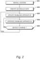
- Step 201 the system is installed and at step 202 schedule data is created.
- the schedule data created at step 202 relates to schedules for normal operation following the fixed constraints, mainly to ensure that total power consumption does not exceed a predetermined limit.
- a schedule of this type may be supplied to all of the enabling apparatus.
- different schedules of the first type may be supplied to enabling apparatus based on customer preferences and levels of service.
- Step 202 for the creation of schedule data, also includes defining second charging schedules that change the availability of charging opportunities, compared to the first schedules, based on variable constraints.
- the enabling apparatus 104 is updated by the transmission of the first schedule to the enabling apparatus, via the Internet 107, to facilitate charging in accordance with user requirements. Thereafter, at step 204, the enabling apparatus is operated to allow, or prevent, vehicle charging.
- step 205 a question is asked as to whether a change has been detected and if answered in the negative, which would be the usual situation, operation of the enabling apparatus continues at step 204 in accordance with the first charging schedule. However, if the question asked at step 205 is answered in the affirmative, the control units are again updated at step 203 and operation at step 204 is then performed in accordance with the second charging schedule. Thus, this will continue until a change is again detected at step 205.
- FIG. 3 An example of a user interface device 105 is shown in Figure 3 and includes a processor 301 that communicates with input devices and a graphical display 302.
- the graphical display 302 presents a graphical user interface 303 to an operative to facilitate the establishment of schedules, possibly created on a daily basis or on a weekly basis.
- the processor 301 communicates with the data storage device 114 and an Internet connection 306 provides a connection to the Internet 107.
- a specific enabling apparatus may be identified in a first region 311.
- a first column 312 allows time intervals to be specified and for each specified time interval, a second column 313 allows entries to be made to state whether charging is possible or whether charging is to be inhibited.
- the processor 301 After establishing a schedule for a particular enabling apparatus, the processor 301 writes details to the data storage device 114 from which schedule data can be derived for transmission to the selected enabling apparatus 104.
- schedules are also be created that take account of variable constraints. Thus, these can be deployed to effect changes due to local generation conditions, expected weather conditions or emergency conditions etc.
- a weekly schedule is established which, in an embodiment, involves interacting with the user interface device 105.
- the established weekly schedule may at this stage be considered as something that can be presented to an operative and, possibly, to a customer during an interactive session of schedule establishment.
- the established weekly schedule is processed to produce schedule data.
- it is the schedule data produced at step 402 that is written to the data storage device 114 at step 403.
- a question is asked as to whether a further schedule is to be established and when answered in the affirmative, the next weekly schedule is established at step 401.
- a schedule may be specified for each individual day.
- schedule data could be downloaded on a daily basis and it may be necessary to download new schedule data each day.
- a decision may be taken as to whether a standard first charging schedule is downloaded, having encountered no variable constraints, or whether an appropriate second schedule is downloaded having encountered a variable constraint.
- FIG. 5 An example of a graphical user interface is illustrated in Figure 5 .
- a specific user may be identified at 501 which in turn relates to a specific enabling apparatus, such as enabling apparatus 104.
- this schedule relates substantially to normal operation when no unusual events have been detected.
- alternative schedules can be produced of the second type which are deployed when variable constraints are detected.
- a service type is identified at 502. For a type 1 schedule, this takes account of fixed constraints applicable to all users or applicable to a specific user - if differing qualities of service are available.
- the service type 502 may identify specific type 2 schedules that take account of different variable constraints. Thus, compared to a standard type 1 schedule, a type 2 schedule may increase or decrease available charging slots depending upon the nature of the variable constraint.
- the weekly schedule is divided into a midweek schedule 503 and weekend schedule 504.
- the midweek schedule 503 represents a midweek day (Monday to Friday) with the weekend schedule 504 representing a weekend day of Saturday or Sunday.
- Each day is then divided into contiguous slots of less than one hour.
- the slots are contiguous to ensure that there are no times during which the availability of charge is ambiguous.
- the actual duration of these timeslots may vary but, in an embodiment, the contiguous intervals are of substantially similar duration.
- the contiguous timeslots may have a duration of between five minutes and thirty minutes. In the embodiment shown in Figure 5 , the contiguous timeslots have a duration of thirty minutes, such that forty-eight timeslots of equal duration are present within each twenty-four-hour day. Thus, in this way, it is possible for the schedule to be interrogated during each time slot to determine whether charging is to be permitted or inhibited, as described with reference to Figure 10 .
- shaded regions such as a first shaded region 511, a second shaded region 512, a third shaded region 513 and a fourth shaded region 514 represent intervals (consisting of one or more timeslots) during which electric vehicle charging is permitted.
- unshaded regions such as a first unshaded region 521, a second unshaded region 522 and a third unshaded region 523 represent intervals during which the charging of electric vehicles is inhibited.
- this schedule when producing this schedule, it is possible, within the graphical user interface, for an operative to mouseover the region in order to change a timeslot from one during which charging is not permitted to one during which charging is permitted. In an alternative embodiment, mouse clicking of individual timeslots may be required.
- charging is permitted from midnight to 7:00am, then from 10:00am to twelve noon, from 2:00pm to 4:00pm and then from 10:00pm to twelve midnight. At other times, charging is not permitted.
- the weekly schedule described with reference to Figure 5 provides contiguous timeslots that have a duration of thirty minutes.
- the contiguous timeslots may have any duration and an embodiment may allow adjustment between timeslots of five minutes and intervals of thirty minutes.
- each timeslot such as unshaded timeslot 601 has a duration of fifteen minutes.
- a charging region 602 has been defined that will allow charging to take place from 10:15 to 12:30.
- a weekly schedule of the type described with reference to Figure 5 , is established and from this, schedule data is produced, as indicated at step 202.
- schedule data is produced, as indicated at step 202.
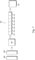
- An example of the production of schedule data is illustrated in Figure 7 .
- Processor 301 converts the weekly schedule to schedule data 701 and writes this schedule data to the schedule data storage device 114; such that the schedule data is then available to be downloaded to an enabling apparatus.
- the schedule data 701 identifies contiguous charging timeslots over a full seven-day weekly period.
- the schedule data may consist of a first portion 711 for Monday, a second portion 712 for Tuesday, a third portion 713 for Wednesday, a fourth portion 714 for Thursday, a fifth portion 715 for Friday, a sixth portion 716 for Saturday and a seventh portion 717 for Sunday.
- each day of the week is specified for the enabling apparatus, with each day having its own contiguous timeslots, identifying intervals during which charging is possible and intervals during which charging is not possible.
- each specific day or week must receive its own assigned schedule data and if data has not been received for a specific day, charging is permanently disabled until new schedule data is received. In this way, all enabling apparatus are disabled (to prevent charging) if a fault condition exists and charging schedule data cannot be downloaded.
- FIG. 8 An example of an enabling apparatus 104 is shown in Figure 8 , connected between the alternating current supply 101 and a charging outlet 801.
- the charging outlet 801 may be a dedicated unit installed for the purposes of charging an electric vehicle.
- an external charging device 103 may be connected to the charging outlet 801.
- the enabling apparatus 104 includes mechanical attachments 803 for securing the apparatus at a position between a domestic distribution consumer unit and the charging outlet 801.
- the apparatus includes a communication device 901 which may establish radio communication within the environment of a dwelling. This in turn provides communication via the Internet 107 to the distributor 106, allowing schedule data to be downloaded.
- the enabling apparatus may be connected to a cellular data network
- data relating to confirmation of use may be uploaded.
- a switching device 902 selectively connects the alternating current supply 101 to the charging outlet 801.
- a processor 903 determines whether the electrical output can be activated to supply electricity to the charging outlet by making reference to the schedule data, as described with reference to Figure 10 .
- the processor 903 selectively activates a switching device 902 in accordance with the respective locally stored weekly schedule data.
- schedule data received from the distributor 106 is stored locally in a local database 904 that is in communication with the processor 903.
- database 904 may store output data identifying when charging has actually taken place.
- the switching device 902 comprises a plurality of cascaded relays.
- three cascaded relays are provided, comprising a first relay 911, a second relay 912 and a third relay 913. Electricity from the alternating current supply is supplied directly to the third relay 913 over a powerline.
- the processor 903 includes an output port 915 configured to supply a relatively low voltage control signal to the first relay 911.
- the first relay 911 and the second relay 912 receive power from a local power supply 916 at appropriate voltages derived from the alternating current supply 101. Activation of the first relay 911 results in the activation of the second relay 912, effectively amplifying the level of the control signal, such that sufficient current is provided to activate the third relay 913.
- a Hall effect detector 917 monitors current flowing to control the third relay 913, thereby providing output data specifying that the third relay has been activated and confirming that power has been made available to the charging outlet 801.
- Procedures performed by the processor 903 are detailed in Figure 10 .
- a question is asked at step 1001 as to whether new data is available. That is to say, does the distributor 106 have new schedule data that is to replace existing schedule data.
- the data is downloaded at step 1002 and an acknowledgement is then provided back to the distributor 106 at step 1003.
- the schedule data includes a checksum in addition to the data described with reference to Figure 7 .
- a parity check is made with reference to this checksum and if an error is identified, this condition is sent back to the distributor which will in turn downloads the data again.
- this condition may also be identified back to the distributor 106.
- the volume of data transmitted is relatively small.
- the downloaded data may be retransmitted back to the distributor 106, which in turn may perform a comparison between what was transmitted and what was received back. If the two datasets are equivalent, this condition may be notified back to the processor 903 indicating that a successful download has occurred.
- a fault condition may be identified and the process may be repeated.
- the question asked at step 1004 will be answered in the affirmative, to the effect that the download has been successful; unless a serious equipment fault exists, which requires maintenance. Under fault conditions, the enabling apparatus 104 is disabled, such that no charging events may occur until the equipment has been restored to a fully functional condition.
- the processor 903 is now in a state suitable for operating locally and a real-time clock is read at step 1005.
- a real-time clock is read at step 1005.
- the real-time clock identifies a time of 8:25:23 on a Wednesday. Referring to the schedule shown in Figure 5 , this falls within interval 521 and the specific timeslot (between 8:00am and 8:30) confirms that charging is not possible.
- a question is asked as to whether data is available at step 1007. Following the above example, this question will be answered in the affirmative and the deactivation of the apparatus will be confirmed at step 1008. The procedure then returns to step 1001 to consider whether new data has been received.
- the procedure may return to step 1005 and repeat the reading of the clock and the identification of timeslots. These procedures are performed continually until an interrupt is received.
- the arrival of new data creates an interrupt and the servicing of this interrupt results in the execution of steps similar to steps 1002 to 1004.
- the two procedures could be specified as individual threads within the programming structure.
- the resulting functionality is substantially similar, in that the interrogation of schedule data will continue to be performed until new data is available.
- a question is asked at step 1007 as to whether data is available. If this question Is answered in the negative, the system is deactivated at step 1009. Thereafter, a question is asked at step 1010 as to whether a full shutdown is to occur and the process stops if this question is answered in the affirmative. Alternatively, If the question asked at step 1010 is answered in the negative, control is returned to step 1001 to enquire as to whether new data is available.
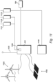
- the alternating current supply 101 is shown in Figure 11 , providing charging current to the enabling apparatus 104.
- Alternating current may be supplied to the alternating current supply 101 from a grid-connected mains supply 1101.
- energy may be received from locally generated sources.
- energy is received from wind generators 1102 and solar generators 1103.
- energy is only available from locally generated sources and a distribution system established within the environment may be identified as a microgrid.
- energy is only received from a national grid connection 1101.
- the total amount of energy received in this way may be limited due to physical constraints or contractual constraints, each representing fixed constraints.
- a detector 1104 is provided that is configured to detect the availability of locally generated energy; from the wind source 1102 or from the solar source 1103 or from a combination of these.
- the detector 1104 provides an output, representing the availability of locally generated energy, to a first constraint generator 1111 and to a second constraint generator 1112.
- the first constraint generator 1111 provides an output to the distributor 106 when an increased level of locally generated energy is detected, resulting in the downloading of a second schedule that increases the number of slots during which charging is enabled; as described with reference to Figure 12 .
- the second constraint generator 1112 provides an output to the distributor 106 when a reduced level of locally generated energy is detected, such that the second schedule decreases the number of slots during which charging is enabled; as described with reference to Figure 13 .
- An emergency shutdown device 1105 is also provided which conveys an output signal to a third constraint generator 1113.
- the emergency shutdown device 1105 may detect an emergency condition at the site of locally generated energy. This may be connected to other emergency signal generating equipment, such as a fire alarm system. Furthermore, the activation of a device in this way may impose other stricter shutdown constraints upon the system as a whole. However, as part of this, appropriate schedules of the second type may be downloaded to prevent the charging of electric vehicles while this emergency condition persists.
- the system described with reference to Figure 1 to Figure 11 facilitates the implementation of a method of restricting the charging of electric vehicles, in which a vehicle receives charge from an alternating current supply via an enabling apparatus 104 and the enabling apparatus receives a schedule identifying charging times during which charging is enabled and non-charging times during which charging is not enabled.
- a first charging schedule ( Figure 5 ) is established based on the requirements of a user and fixed constraints placed upon the availability of charging energy. Thus, a user may be required to charge a vehicle during each day of the week and the energy available within the system as a whole is only sufficient to permit the charging of vehicles outside the intervals of peak demand.
- the method defines a second charging schedule that changes the availability of charging opportunities compared to the first schedule based on a variable constraint.
- a variable constraint may exist and these constraints may vary to differing degrees.
- second charging schedules also referred to as charging schedules of the second type.
- the first schedule is transmitted to connected enabling apparatus, in the form of schedule data in an embodiment, to facilitate charging in accordance with user requirements.
- the system is in a position to detect the presence of a variable constraint.
- the second charging schedule is transmitted to the connected enabling apparatus, thereby changing the charging availability and accommodating the variable constraint; without mental anticipation or manual interaction.
- a variable constraint is based on the availability of locally generated energy.
- the fixed constraint may be defined such as to facilitate charging when electricity generation is expected; that is to say, when it is expected that the wind will be blowing and/or when it is expected that the sun will be shining.
- variations occur, such that a greater level of energy may be produced on windy/sunny days and less energy may be produced on calm/dull days.
- the detector 1104 identifies the amount of energy that is being generated locally and provides this information to the first constraint generator 1111 and to the second constraint generator 1112.
- the first constraint generator 1111 identifies conditions where the amount of energy being generated exceeds an expected level by a predetermined amount.
- a signal is supplied to the distributor 106 which then transmits a second charging schedule to encourage greater local consumption of the locally generated energy.
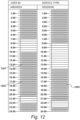
- An example of such a schedule is shown in Figure 12 .
- the schedule described with reference to Figure 5 has previously been transmitted as the first schedule.
- the schedule is similar but has been enhanced, such that charging is now possible during an interval 1201 from 12:00 noon to 2:00pm. Furthermore, charging is now possible during a second interval 1202 between 4:00pm and 8:30pm.
- the schedule shown in Figure 12 from which schedule data is produced, may be identified as a schedule of the second type applicable when more generation is possible.
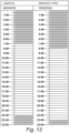
- the alternative condition to that described with reference to Figure 12 is shown in Figure 13 .
- the second constraint generator 1112 has detected a condition to the effect that less energy is being generated than expected.
- the schedule shown in Figure 13 is a schedule of the second type, during which less energy generation is possible. Charging is no longer permitted midweek between 10:00am and 12:00 noon. Furthermore, charging is no longer possible between 2:00pm and 4:00pm. Such a condition is likely to occur if local energy generation is severely limited and energy is only available from the grid supply 1101, such that vehicle charging is only possible during off-peak periods.
- Activation of emergency device 1105 is detected by the third constraint generator 1113, which in turn conveys this information to the distributor 106.
- the distributor selects and downloads a schedule of the second type which may be referred to as a maintenance schedule, as illustrated in Figure 14 .
- the schedule shown in Figure 14 effectively represents a complete shutdown, in that charging is not possible at any time.
- the question asked at step 1007 would be answered in the negative and the deactivation would occur at step 1009.
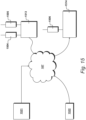
- a fourth constraint generator 1504 is shown in Figure 15 , along with a fifth constraint generator 1505 and the sixth constraint generator 1506. Each of these provide outputs to the distributor 106.
- a third detector 1513 receives weather report data via the Internet 107 from a weather data source 1521. The detector identifies weather conditions that improve local energy generation such that a second schedule may be downloaded that increases the number of slots during which charging is enabled. Thus, the fourth constraint generator supplies an output signal to the distributor for identifying periods of good weather so that an adjustment may be made to provide more charging slots.
- the third detector 1513 identifies weather conditions that will increase domestic demand for energy, resulting in the distribution of a second schedule that decreases the number of slots during which charging is enabled.
- the fifth constraint generator supplies an output signal to the distributor 106 identifying periods when domestic demand may be high and vehicle charging opportunities must be reduced.
- a second source of data 1522 supplies event related data to a fourth detector 1514 via the Internet 107.
- the event detector may identify particular events which, irrespective of the weather, may increase domestic demand and thereby reduce the availability of energy for charging electric vehicles. Such events may include Bank Holidays for example or major sporting events etc.
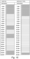
- FIG. 16 A further schedule of the second type is shown in Figure 16 .
- charging is now not available between 4:30am and 7:00am on a midweek day.
- charging is no longer possible between 5:30 and 8:00am.
- variable constraint may be detected by measuring the amount of energy generated locally and detecting a shortfall or a surplus.
- the variable constraint may be detected from weather report data or the variable constraint may represent an extreme condition during which all vehicle charging is to be prevented.
- the variable constraint may be detected in response to an output signal generated by an emergency system.
- the variable constraint could be detected in response to network data from a remote source providing an advance warning of a required shutdown, possibly due to weather conditions or possibly due to an anticipated unusual event that will place an unusual demand on domestic consumption.
Landscapes
- Engineering & Computer Science (AREA)
- Power Engineering (AREA)
- Transportation (AREA)
- Mechanical Engineering (AREA)
- Life Sciences & Earth Sciences (AREA)
- Sustainable Development (AREA)
- Sustainable Energy (AREA)
- Charge And Discharge Circuits For Batteries Or The Like (AREA)
Abstract
A system is shown for restricting the charging of electric vehicles and includes an alternating current supply 101 for charging an electric vehicle 102; an enabling apparatus 104 connected between the alternating current supply and the electric vehicle; a user interface device 105 for establishing charging schedules, in which a charging period is divided into a plurality of charging slots; and a detector for detecting the presence of a variable constraint. A first charging schedule is established via the user interface device based on the requirements of a user and fixed constraints placed upon the availability of charging energy. A second charging schedule is defined via the user interface device that changes the availability of charging opportunities compared to the first schedule based on a variable constraint. The first schedule is transmitted to the enabling apparatus to facilitate charging in accordance with the requirements of the user. However, if the detector detects the presence of a variable constraint, the second charging schedule is transmitted to the enabling apparatus to accommodate changes to the availability of charging energy.
Description
- The present invention relates to a method of restricting the charging of electric vehicles, of the type in which a vehicle receives charge from an alternating current supply via an enabling apparatus and said enabling apparatus receives a schedule identifying charging times during which charging is enabled and non-charging times during which charging is not enabled.
- The present invention also relates to a system for restricting the charging of electric vehicles, of the type comprising: an alternating current supply for charging an electric vehicle; an enabling apparatus connected between said alternating current supply and an electric vehicle; a user interface device for establishing charging schedules, in which a charging period is divided into a plurality of charging slots; a distributor for distributing a schedule to an enabling apparatus; and a detector for detecting the presence of a variable constraint,
- An apparatus for controlling the charging of an electric vehicle from a domestic supply of electricity (typically an AC supply) is shown in
GB 2601308 - In the context of the present invention, the power management commands may be derived from a first charging schedule based on the requirements of a user and fixed constraints placed upon the availability of charging energy. These fixed constraints may be determined by the total availability of energy available to a housing estate for example. This energy may be received from a national grid supply, from local generation equipment or from a combination of these two. The fixed constraints therefore relate to constraints placed on the system most of the time and, for example, may restrict charging during peak intervals during which substantial amounts of energy are required for other purposes. Thus, the first charging schedule primarily allows charging during off-peak periods to ensure that, at any point in time, the total power consumption does not exceed a predetermined level.
- The inventors have identified problems with the known system, particularly when unforeseen events occur that may be identified generally as variable constraints. Thus, although schedules may be modified manually and downloaded, opportunities may be missed for increasing the availability of charging opportunities when additional energy is available, possibly due to decreased demand on warm days or increased generation capacity. Similarly, it may be necessary to reduce charging opportunities, possibly due to increased demand due to bad weather or reduced availability due to maintenance or an emergency condition.
- According to a first aspect of the present invention, there is provided a method of restricting the charging of electric vehicles of the aforesaid type characterized by the steps of: establishing a first charging schedule based on the requirements of a user and fixed constraints placed upon the availability of charging energy; defining a second charging schedule that changes the availability of charging opportunities compared to the first schedule based on a variable constraint; transmitting said first schedule to connected enabling apparatus to facilitate charging in accordance with user requirements; detecting the presence of a variable constraint; and transmitting said second charging schedule to said connected enabling apparatus in response to said detecting step, thereby changing charging availability and accommodating the variable constraint.
- In an embodiment, a fixed constraint comprises a limit on a maximum power level, wherein non-charging times are identified during regular times of peak demand. A variable constraint may be based on the availability of locally generated energy, wherein charging times are identified during regular times of peak demand to encourage greater local consumption of said locally generated energy. The variable constraint may be detected by measuring the amount of energy generated locally and detecting a surplus.
- In an embodiment, a variable constraint is based on the availability of locally generated energy, wherein non-charging times are expanded to reduce consumption of locally generated energy. The variable constraint may be detected by measuring the amount of energy generated locally and detecting a short-fall. Alternatively, the variable constraint is detected from weather report data. In an embodiment, a variable constraint represents an extreme condition during which all vehicle charging is to be prevented. Furthermore, the variable constraint may be detected in response to an output signal generated by an emergency system. Alternatively, the variable constraint may be detected in response to network data from a remote source providing an advance warning of a required shut-down.
- According to a second aspect of the present invention, there is provided a system for restricting the charging of electric vehicles of the aforesaid type, characterized in that: a first charging schedule is established via said user interface device based on the requirements of a user and fixed constraints placed upon the availability of charging energy; a second charging schedule is defined via said user interface device that changes the availability of charging opportunities compared to said first schedule based on a variable constraint; the first schedule is transmitted to the enabling apparatus to facilitate charging in accordance with the requirements of the user; and upon said detector detecting the presence of a variable constraint, said second charging schedule is transmitted to the enabling apparatus to accommodate changes to the availability of charging energy.
- Embodiments of the invention will be described, by way of example only, with reference to the accompanying drawings. The detailed embodiments show the best mode known to the inventor and provide support for the invention as claimed. However, they are only exemplary and should not be used to interpret or limit the scope of the claims. Their purpose is to provide a teaching to those skilled in the art. Components and processes distinguished by ordinal phrases such as "first" and "second" do not necessarily define an order or ranking of any sort. In the drawings:
-
Figure 1 shows a system for restricting the charging of electric vehicles; -
Figure 2 illustrates operation of the system identified inFigure 1 -
Figure 3 shows an example of a user interface device; -
Figure 4 shows operations performed by the processor identified inFigure 3 ; -
Figure 5 shows an example of a graphical user interface; -
Figure 6 shows an example of a weekly schedule with fifteen-minute timeslots; -
Figure 7 shows the production of schedule data from a weekly schedule; -
Figure 8 shows an example on an enabling apparatus; -
Figure 9 shows a schematic representation of the enabling apparatus identified inFigure 1 ; -
Figure 10 details procedures performed by the processor identified inFigure 9 ; -
Figure 11 shows the generation and monitoring of energy locally; -
Figure 12 shows a second charging schedule produced when a variable constraint identifies greater charging availability; -
Figure 13 shows a second charging schedule downloaded when a variable constraint indicates that less charging energy will be available; -
Figure 14 shows a second charging schedule downloaded in response to an emergency condition being identified as a variable constraint; -
Figure 15 shows the deployment of further constraint generators; and -
Figure 16 shows a further schedule of the second type. - A system for restricting the charging of electric vehicles is shown in
Figure 1 . An alternatingcurrent supply 101 is provided for charging anelectric vehicle 102. In this embodiment, the electric vehicle has anexternal charging device 103 for receiving electricity from thesource 101 and communicating with thevehicle 102. Thus, if power is available and thevehicle 102 requires charge, thedevice 103 will connect themains supply 101 to thevehicle 102. - In accordance with the invention, there is also provided an
enabling apparatus 104 between the alternatingcurrent supply 101 and thevehicle 102. As described inGB 2601308 apparatus 104 to allow charging or to prevent charging at selected slots as defined by a schedule. - A
user interface device 105 is provided for establishing charging schedules, in which a charging period (typically a day or a week) is divided into a plurality of charging slots. These schedules are distributed by adistributor 106, typically connected to the Internet 107, to distribute the schedules to the enabling apparatus, including enablingapparatus 104. In a typical environment, many enabling apparatus will be provided to facilitate the simultaneous charging of a plurality of electric vehicles; possibly within a housing estate. Thus, it is possible for theuser interface 105 to be responsible for establishing charging schedules for many users. - The system also includes at least one detector detecting the presence of a variable constraint. In an embodiment, the first variable constraint may relate to the availability of energy (possibly from local renewable sources), the second variable constraint may relate to weather conditions and a third variable constraint may relate to emergency conditions. Each of these provides an automatic detection of variable constraints and supplies data to the
distributor 106. - In the environment of
Figure 1 , a first charging schedule is established via theuser interface device 105 based on the requirements of a user and fixed constraints placed upon the availability of charging energy. In addition, a second charging schedule is defined via theuser interface 105 that changes the availability of charging opportunities, compared to the first schedule, based on a variable constraint. These schedules are stored in a scheduledata storage device 114 that is configured to receive data from theinterface device 105. Thedistributor 106 is configured to select appropriate schedule data from the scheduledata storage device 114 and convey this to selected enabling apparatus. Thus, when deployed, the first schedule is transmitted to the enablingapparatus 104 to facilitate charging in accordance with the requirements of the user. However, upon detecting the presence of a variable constraint, the second charging schedule is transmitted to the enabling apparatus to accommodate changes to the availability of charging energy. - In an embodiment, a plurality of second schedules are stored suitable for changing the availability of charging slots in response to a plurality of variable constraints. A plurality of detectors are provided (111 to 113) for detecting respective variable constraints, resulting in the selection of an appropriate second schedule.
- In an embodiment, the system includes a
machine learning apparatus 121. The machine learning apparatus receives details of variable constraints when they occur and also receives details of the resulting downloaded second schedule. Manual input details are then supplied to themachine learning apparatus 121 via theuser interface device 105. After receiving a significant number of datasets, themachine learning apparatus 121 is then in a position to make suggestions for improving the second schedules, which involves changing the actual nature of the second schedules, in terms of slots when charging can occur and when charging cannot occur. In addition, this may also involve providing advice in terms of when a second schedule should be deployed. Thus, for example, over time, the machine learning apparatus should improve the effectiveness of deploying the appropriate second schedule for a particular anticipated weather event. - Operation of the system, described with reference to
Figure 1 , is illustrated inFigure 2 . Atstep 201 the system is installed and atstep 202 schedule data is created. The schedule data created atstep 202 relates to schedules for normal operation following the fixed constraints, mainly to ensure that total power consumption does not exceed a predetermined limit. A schedule of this type may be supplied to all of the enabling apparatus. Alternatively, different schedules of the first type may be supplied to enabling apparatus based on customer preferences and levels of service. -
Step 202, for the creation of schedule data, also includes defining second charging schedules that change the availability of charging opportunities, compared to the first schedules, based on variable constraints. - At
step 203, the enablingapparatus 104 is updated by the transmission of the first schedule to the enabling apparatus, via theInternet 107, to facilitate charging in accordance with user requirements. Thereafter, atstep 204, the enabling apparatus is operated to allow, or prevent, vehicle charging. - At
step 205, a question is asked as to whether a change has been detected and if answered in the negative, which would be the usual situation, operation of the enabling apparatus continues atstep 204 in accordance with the first charging schedule. However, if the question asked atstep 205 is answered in the affirmative, the control units are again updated atstep 203 and operation atstep 204 is then performed in accordance with the second charging schedule. Thus, this will continue until a change is again detected atstep 205. - An example of a
user interface device 105 is shown inFigure 3 and includes aprocessor 301 that communicates with input devices and agraphical display 302. Thegraphical display 302 presents agraphical user interface 303 to an operative to facilitate the establishment of schedules, possibly created on a daily basis or on a weekly basis. Furthermore, theprocessor 301 communicates with thedata storage device 114 and anInternet connection 306 provides a connection to theInternet 107. - Within the
graphical user interface 303, a specific enabling apparatus may be identified in afirst region 311. Afirst column 312 allows time intervals to be specified and for each specified time interval, asecond column 313 allows entries to be made to state whether charging is possible or whether charging is to be inhibited. - After establishing a schedule for a particular enabling apparatus, the
processor 301 writes details to thedata storage device 114 from which schedule data can be derived for transmission to the selected enablingapparatus 104. - In addition to creating schedule data for normal operation, schedules are also be created that take account of variable constraints. Thus, these can be deployed to effect changes due to local generation conditions, expected weather conditions or emergency conditions etc.
- Operations performed by the
processor 301 to create schedule data, as identified inFigure 2 , are detailed inFigure 4 . Atstep 401, a weekly schedule is established which, in an embodiment, involves interacting with theuser interface device 105. Thus, the established weekly schedule may at this stage be considered as something that can be presented to an operative and, possibly, to a customer during an interactive session of schedule establishment. - At
step 402, the established weekly schedule is processed to produce schedule data. In this embodiment, it is the schedule data produced atstep 402 that is written to thedata storage device 114 atstep 403. Thereafter, atstep 404, a question is asked as to whether a further schedule is to be established and when answered in the affirmative, the next weekly schedule is established atstep 401. - As an alternative to producing daily schedule data from a weekly schedule, a schedule may be specified for each individual day. Furthermore, schedule data could be downloaded on a daily basis and it may be necessary to download new schedule data each day. Thus, each day, a decision may be taken as to whether a standard first charging schedule is downloaded, having encountered no variable constraints, or whether an appropriate second schedule is downloaded having encountered a variable constraint.
- An example of a graphical user interface is illustrated in
Figure 5 . A specific user may be identified at 501 which in turn relates to a specific enabling apparatus, such as enablingapparatus 104. Thus, this schedule relates substantially to normal operation when no unusual events have been detected. However, as described with reference toFigure 12 to Figure 14 , alternative schedules can be produced of the second type which are deployed when variable constraints are detected. - A service type is identified at 502. For a
type 1 schedule, this takes account of fixed constraints applicable to all users or applicable to a specific user - if differing qualities of service are available. In addition, theservice type 502 may identifyspecific type 2 schedules that take account of different variable constraints. Thus, compared to astandard type 1 schedule, atype 2 schedule may increase or decrease available charging slots depending upon the nature of the variable constraint. - In the example shown in
Figure 5 , the weekly schedule is divided into amidweek schedule 503 andweekend schedule 504. Themidweek schedule 503 represents a midweek day (Monday to Friday) with theweekend schedule 504 representing a weekend day of Saturday or Sunday. Each day is then divided into contiguous slots of less than one hour. The slots are contiguous to ensure that there are no times during which the availability of charge is ambiguous. The actual duration of these timeslots may vary but, in an embodiment, the contiguous intervals are of substantially similar duration. - The contiguous timeslots may have a duration of between five minutes and thirty minutes. In the embodiment shown in
Figure 5 , the contiguous timeslots have a duration of thirty minutes, such that forty-eight timeslots of equal duration are present within each twenty-four-hour day. Thus, in this way, it is possible for the schedule to be interrogated during each time slot to determine whether charging is to be permitted or inhibited, as described with reference toFigure 10 . - In this embodiment, as shown in
Figure 5 , shaded regions, such as a firstshaded region 511, a secondshaded region 512, a thirdshaded region 513 and a fourthshaded region 514 represent intervals (consisting of one or more timeslots) during which electric vehicle charging is permitted. Similarly, the unshaded regions, such as a firstunshaded region 521, a secondunshaded region 522 and a thirdunshaded region 523 represent intervals during which the charging of electric vehicles is inhibited. - In an embodiment, when producing this schedule, it is possible, within the graphical user interface, for an operative to mouseover the region in order to change a timeslot from one during which charging is not permitted to one during which charging is permitted. In an alternative embodiment, mouse clicking of individual timeslots may be required.
- In accordance with this being a schedule of the first type, charging is permitted from midnight to 7:00am, then from 10:00am to twelve noon, from 2:00pm to 4:00pm and then from 10:00pm to twelve midnight. At other times, charging is not permitted.
- In this example, the availability of charging slots over the weekend is more restricted. As shown in
Figure 5 , charging is allowed overnight from midnight until 8:00pm (whereas it is only allowed until 7:00am during weekdays). However, for most of the day, charging is not possible and only becomes possible again after 11:00pm. - The weekly schedule described with reference to
Figure 5 provides contiguous timeslots that have a duration of thirty minutes. In other embodiments, the contiguous timeslots may have any duration and an embodiment may allow adjustment between timeslots of five minutes and intervals of thirty minutes. - In the example shown in
Figure 6 , each timeslot, such asunshaded timeslot 601, has a duration of fifteen minutes. Thus, as can be seen inFigure 6 , between 9:00am and 10:00am there are four programmable timeslots. In this example, a chargingregion 602 has been defined that will allow charging to take place from 10:15 to 12:30. - In an embodiment, a weekly schedule, of the type described with reference to
Figure 5 , is established and from this, schedule data is produced, as indicated atstep 202. An example of the production of schedule data is illustrated inFigure 7 . - As previously described, a
mid-week schedule 503 has been produced along with aweekend schedule 504.Processor 301 converts the weekly schedule to scheduledata 701 and writes this schedule data to the scheduledata storage device 114; such that the schedule data is then available to be downloaded to an enabling apparatus. - The
schedule data 701 identifies contiguous charging timeslots over a full seven-day weekly period. Thus, in this embodiment, the schedule data may consist of afirst portion 711 for Monday, asecond portion 712 for Tuesday, athird portion 713 for Wednesday, afourth portion 714 for Thursday, afifth portion 715 for Friday, asixth portion 716 for Saturday and aseventh portion 717 for Sunday. Thus, each day of the week is specified for the enabling apparatus, with each day having its own contiguous timeslots, identifying intervals during which charging is possible and intervals during which charging is not possible. - In an alternative embodiment, it is possible for data to be downloaded on a daily basis. In an embodiment, each specific day or week must receive its own assigned schedule data and if data has not been received for a specific day, charging is permanently disabled until new schedule data is received. In this way, all enabling apparatus are disabled (to prevent charging) if a fault condition exists and charging schedule data cannot be downloaded.
- In a further alternative embodiment, it is not necessary to download new schedule data and weekly schedule data continues to be used until new data is received. However, heartbeat signals are regularly exchanged between the distributor and each enabling apparatus and an enabling apparatus is permanently disabled (charging not being allowed) if its connection to the distributor is lost.
- An example of an enabling
apparatus 104 is shown inFigure 8 , connected between the alternatingcurrent supply 101 and a chargingoutlet 801. The chargingoutlet 801 may be a dedicated unit installed for the purposes of charging an electric vehicle. Alternatively, anexternal charging device 103 may be connected to the chargingoutlet 801. - In an embodiment, the enabling
apparatus 104 includesmechanical attachments 803 for securing the apparatus at a position between a domestic distribution consumer unit and the chargingoutlet 801. - A schematic representation of the enabling
apparatus 104 is shown inFigure 9 . The apparatus includes acommunication device 901 which may establish radio communication within the environment of a dwelling. This in turn provides communication via theInternet 107 to thedistributor 106, allowing schedule data to be downloaded. Alternatively, the enabling apparatus may be connected to a cellular data network Furthermore, in an embodiment, data relating to confirmation of use may be uploaded. - A
switching device 902 selectively connects the alternatingcurrent supply 101 to the chargingoutlet 801. Aprocessor 903 determines whether the electrical output can be activated to supply electricity to the charging outlet by making reference to the schedule data, as described with reference toFigure 10 . Thus, theprocessor 903 selectively activates aswitching device 902 in accordance with the respective locally stored weekly schedule data. - In an embodiment, schedule data received from the
distributor 106 is stored locally in alocal database 904 that is in communication with theprocessor 903. Furthermore,database 904, or an alternative database, may store output data identifying when charging has actually taken place. - In an embodiment, the
switching device 902 comprises a plurality of cascaded relays. In the embodiment illustrated inFigure 9 , three cascaded relays are provided, comprising afirst relay 911, asecond relay 912 and athird relay 913. Electricity from the alternating current supply is supplied directly to thethird relay 913 over a powerline. - The
processor 903 includes anoutput port 915 configured to supply a relatively low voltage control signal to thefirst relay 911. Thefirst relay 911 and thesecond relay 912 receive power from alocal power supply 916 at appropriate voltages derived from the alternatingcurrent supply 101. Activation of thefirst relay 911 results in the activation of thesecond relay 912, effectively amplifying the level of the control signal, such that sufficient current is provided to activate thethird relay 913. - In an embodiment, a
Hall effect detector 917 monitors current flowing to control thethird relay 913, thereby providing output data specifying that the third relay has been activated and confirming that power has been made available to the chargingoutlet 801. - Procedures performed by the
processor 903 are detailed inFigure 10 . After start-up, a question is asked atstep 1001 as to whether new data is available. That is to say, does thedistributor 106 have new schedule data that is to replace existing schedule data. When answered in the affirmative, the data is downloaded atstep 1002 and an acknowledgement is then provided back to thedistributor 106 atstep 1003. - In an embodiment, the schedule data includes a checksum in addition to the data described with reference to
Figure 7 . Thus, at theprocessor 903, a parity check is made with reference to this checksum and if an error is identified, this condition is sent back to the distributor which will in turn downloads the data again. Similarly, if the checksum is successful, this condition may also be identified back to thedistributor 106. - It is also appreciated that the volume of data transmitted is relatively small. Thus, in an embodiment, it is possible for the downloaded data to be retransmitted back to the
distributor 106, which in turn may perform a comparison between what was transmitted and what was received back. If the two datasets are equivalent, this condition may be notified back to theprocessor 903 indicating that a successful download has occurred. Alternatively, if the datasets differ, a fault condition may be identified and the process may be repeated. Thus, eventually, the question asked atstep 1004 will be answered in the affirmative, to the effect that the download has been successful; unless a serious equipment fault exists, which requires maintenance. Under fault conditions, the enablingapparatus 104 is disabled, such that no charging events may occur until the equipment has been restored to a fully functional condition. - The
processor 903 is now in a state suitable for operating locally and a real-time clock is read atstep 1005. For the purposes of providing an example, it may be assumed that the real-time clock identifies a time of 8:25:23 on a Wednesday. Referring to the schedule shown inFigure 5 , this falls withininterval 521 and the specific timeslot (between 8:00am and 8:30) confirms that charging is not possible. Thus, after identifying the timeslot atstep 1006, a question is asked as to whether data is available atstep 1007. Following the above example, this question will be answered in the affirmative and the deactivation of the apparatus will be confirmed atstep 1008. The procedure then returns to step 1001 to consider whether new data has been received. - In an alternative embodiment, after
step 1008, the procedure may return to step 1005 and repeat the reading of the clock and the identification of timeslots. These procedures are performed continually until an interrupt is received. Thus, in this alternative embodiment, the arrival of new data creates an interrupt and the servicing of this interrupt results in the execution of steps similar tosteps 1002 to 1004. Furthermore, when constructed using high level programming languages, the two procedures could be specified as individual threads within the programming structure. However, the resulting functionality is substantially similar, in that the interrogation of schedule data will continue to be performed until new data is available. - Even when using relatively inexpensive processing devices, the period between individual interrogations of the schedule data will be in the order of milliseconds. Thus, when new schedule data becomes available, this is rapidly analysed, written to local storage and acted upon. Thus, in this way, it is possible to make relatively rapid changes to the availability of charging opportunities; rapidly operating in response to a second charging schedule as distinct from the previously established first charging schedule.
- In an embodiment, if schedule data is not available, it is not possible for the enabling apparatus to allow the charging of an electric vehicle. To achieve this, as previously stated, a question is asked at
step 1007 as to whether data is available. If this question Is answered in the negative, the system is deactivated atstep 1009. Thereafter, a question is asked atstep 1010 as to whether a full shutdown is to occur and the process stops if this question is answered in the affirmative. Alternatively, If the question asked atstep 1010 is answered in the negative, control is returned to step 1001 to enquire as to whether new data is available. - The alternating
current supply 101 is shown inFigure 11 , providing charging current to the enablingapparatus 104. Alternating current may be supplied to the alternatingcurrent supply 101 from a grid-connected mains supply 1101. In addition, or as an alternative, energy may be received from locally generated sources. Thus, in the example shown inFigure 11 , energy is received fromwind generators 1102 andsolar generators 1103. In some embodiments, energy is only available from locally generated sources and a distribution system established within the environment may be identified as a microgrid. - In alternative embodiments, energy is only received from a
national grid connection 1101. However, the total amount of energy received in this way may be limited due to physical constraints or contractual constraints, each representing fixed constraints. When greater reliance is made upon local generation, possibly within a microgrid environment, greater variations in energy availability are likely to occur and as a result, more variable constraints are likely to occur. - In the embodiment shown in
Figure 11 , a detector 1104 is provided that is configured to detect the availability of locally generated energy; from thewind source 1102 or from thesolar source 1103 or from a combination of these. The detector 1104 provides an output, representing the availability of locally generated energy, to afirst constraint generator 1111 and to asecond constraint generator 1112. Thefirst constraint generator 1111 provides an output to thedistributor 106 when an increased level of locally generated energy is detected, resulting in the downloading of a second schedule that increases the number of slots during which charging is enabled; as described with reference toFigure 12 . Thesecond constraint generator 1112 provides an output to thedistributor 106 when a reduced level of locally generated energy is detected, such that the second schedule decreases the number of slots during which charging is enabled; as described with reference toFigure 13 . - An
emergency shutdown device 1105 is also provided which conveys an output signal to athird constraint generator 1113. Theemergency shutdown device 1105 may detect an emergency condition at the site of locally generated energy. This may be connected to other emergency signal generating equipment, such as a fire alarm system. Furthermore, the activation of a device in this way may impose other stricter shutdown constraints upon the system as a whole. However, as part of this, appropriate schedules of the second type may be downloaded to prevent the charging of electric vehicles while this emergency condition persists. - The system described with reference to
Figure 1 to Figure 11 facilitates the implementation of a method of restricting the charging of electric vehicles, in which a vehicle receives charge from an alternating current supply via an enablingapparatus 104 and the enabling apparatus receives a schedule identifying charging times during which charging is enabled and non-charging times during which charging is not enabled. A first charging schedule (Figure 5 ) is established based on the requirements of a user and fixed constraints placed upon the availability of charging energy. Thus, a user may be required to charge a vehicle during each day of the week and the energy available within the system as a whole is only sufficient to permit the charging of vehicles outside the intervals of peak demand. - In addition, the method defines a second charging schedule that changes the availability of charging opportunities compared to the first schedule based on a variable constraint. In an embodiment, several variable constraints may exist and these constraints may vary to differing degrees. Thus, such an embodiment requires a plurality of second charging schedules; also referred to as charging schedules of the second type.
- The first schedule is transmitted to connected enabling apparatus, in the form of schedule data in an embodiment, to facilitate charging in accordance with user requirements. However, at any time, the system is in a position to detect the presence of a variable constraint. Upon making this detection, the second charging schedule is transmitted to the connected enabling apparatus, thereby changing the charging availability and accommodating the variable constraint; without mental anticipation or manual interaction.
- In an embodiment, a variable constraint is based on the availability of locally generated energy. In this environment, the fixed constraint may be defined such as to facilitate charging when electricity generation is expected; that is to say, when it is expected that the wind will be blowing and/or when it is expected that the sun will be shining. However, as is well known in these environments, variations occur, such that a greater level of energy may be produced on windy/sunny days and less energy may be produced on calm/dull days.
- The detector 1104 identifies the amount of energy that is being generated locally and provides this information to the
first constraint generator 1111 and to thesecond constraint generator 1112. Thefirst constraint generator 1111 identifies conditions where the amount of energy being generated exceeds an expected level by a predetermined amount. In response to making an evaluation of this type, a signal is supplied to thedistributor 106 which then transmits a second charging schedule to encourage greater local consumption of the locally generated energy. An example of such a schedule is shown inFigure 12 . For the purposes of this example, it is assumed that the schedule described with reference toFigure 5 has previously been transmitted as the first schedule. The schedule is similar but has been enhanced, such that charging is now possible during aninterval 1201 from 12:00 noon to 2:00pm. Furthermore, charging is now possible during asecond interval 1202 between 4:00pm and 8:30pm. - Similarly, at the weekend, charging is now possible during a
third interval 1203 between 2:00pm and 9:30pm. Thus, the variable constraint has been detected by measuring the amount of energy generated locally and detecting a surplus. Thus, the schedule shown inFigure 12 , from which schedule data is produced, may be identified as a schedule of the second type applicable when more generation is possible. - The alternative condition to that described with reference to
Figure 12 is shown inFigure 13 . On this occasion, thesecond constraint generator 1112 has detected a condition to the effect that less energy is being generated than expected. To accommodate this, the schedule shown inFigure 13 is a schedule of the second type, during which less energy generation is possible. Charging is no longer permitted midweek between 10:00am and 12:00 noon. Furthermore, charging is no longer possible between 2:00pm and 4:00pm. Such a condition is likely to occur if local energy generation is severely limited and energy is only available from thegrid supply 1101, such that vehicle charging is only possible during off-peak periods. - Activation of
emergency device 1105, either automatically or manually, is detected by thethird constraint generator 1113, which in turn conveys this information to thedistributor 106. The distributor selects and downloads a schedule of the second type which may be referred to as a maintenance schedule, as illustrated inFigure 14 . - The schedule shown in
Figure 14 effectively represents a complete shutdown, in that charging is not possible at any time. In an embodiment, as an alternative to distributing a schedule of the type shown inFigure 14 , it could be possible to download data or a lack of data indicating that schedule data is not available. Thus, under these conditions, the question asked atstep 1007 would be answered in the negative and the deactivation would occur atstep 1009. - The use of a schedule of the second type in accordance with that shown in
Figure 14 would only be used under severe emergency conditions or would only be used for a limited period of time when maintenance operations are being performed and the system must be put off line. However, as used in the art, this does not represent an emergency shutdown condition and may as an alternative be referred to as a soft shutdown condition from which recovery is possible without taking additional safety related measures. Thus, in working environments, other systems, as are known in the art, are provided for creating emergency shutdown conditions when required, whereupon an inspection and an active reset operation would be required to revive the service. - A
fourth constraint generator 1504 is shown inFigure 15 , along with afifth constraint generator 1505 and thesixth constraint generator 1506. Each of these provide outputs to thedistributor 106. Athird detector 1513 receives weather report data via theInternet 107 from aweather data source 1521. The detector identifies weather conditions that improve local energy generation such that a second schedule may be downloaded that increases the number of slots during which charging is enabled. Thus, the fourth constraint generator supplies an output signal to the distributor for identifying periods of good weather so that an adjustment may be made to provide more charging slots. - In addition, the
third detector 1513 identifies weather conditions that will increase domestic demand for energy, resulting in the distribution of a second schedule that decreases the number of slots during which charging is enabled. Thus, the fifth constraint generator supplies an output signal to thedistributor 106 identifying periods when domestic demand may be high and vehicle charging opportunities must be reduced. - It is possible for a sophisticated dynamic to be created and experiment suggests that instabilities and rapid fluctuations can be avoided by deployment of the
machine learning apparatus 121. In particular, the detectors described with reference toFigure 11 indicate changes that are required immediately; whereas, the detectors ofFigure 15 produce data relating to changes that are required in the future. Furthermore, an indication may be provided to the effect that more energy may be available due to strong winds but at the same time a reduction in ambient temperature may indicate that there will be a greater demand for domestic consumption. Thus, initially, these conflicts may be resolved by relatively crude algorithms but over time the response may be refined by deployment of the machine learning process. - A second source of
data 1522 supplies event related data to afourth detector 1514 via theInternet 107. The event detector may identify particular events which, irrespective of the weather, may increase domestic demand and thereby reduce the availability of energy for charging electric vehicles. Such events may include Bank Holidays for example or major sporting events etc. The data Is analysed by thefourth detector 1514 and when appropriate, an output signal is produced by thesixth constraint generator 1506 which is supplied to thedistributor 106, again facilitating the distribution of an appropriate schedule of the second type. - A further schedule of the second type is shown in
Figure 16 . In response to identifying adverse weather conditions, charging is now not available between 4:30am and 7:00am on a midweek day. Furthermore, in anticipation of a major event occurring at the weekend, charging is no longer possible between 5:30 and 8:00am. - Thus, in summary, the variable constraint may be detected by measuring the amount of energy generated locally and detecting a shortfall or a surplus. Alternatively, the variable constraint may be detected from weather report data or the variable constraint may represent an extreme condition during which all vehicle charging is to be prevented. Similarly, the variable constraint may be detected in response to an output signal generated by an emergency system. Furthermore, the variable constraint could be detected in response to network data from a remote source providing an advance warning of a required shutdown, possibly due to weather conditions or possibly due to an anticipated unusual event that will place an unusual demand on domestic consumption.
Claims (15)
- A method of restricting the charging of electric vehicles (102), in which a vehicle receives charge from an alternating current supply (101) via an enabling apparatus (103) and said enabling apparatus receives a schedule identifying charging times during which charging is enabled and non-charging times during which charging is not enabled, characterized by the steps of:establishing a first charging schedule based on the requirements of a user and fixed constraints placed upon the availability of charging energy;defining a second charging schedule that changes the availability of charging opportunities compared to the first schedule based on a variable constraint;transmitting said first schedule to connected enabling apparatus to facilitate charging in accordance with user requirements;detecting the presence of a variable constraint; andtransmitting said second charging schedule to said connected enabling apparatus in response to said detecting step, thereby changing charging availability and accommodating the variable constraint.
- The method of claim 1, characterized in that a fixed constraint comprises a limit on a maximum power level, wherein non-charging times are identified during regular times of peak demand.
- The method of claim 1 or claim 2, characterized in that a variable constraint is based on the availability of locally generated energy, wherein charging times are identified during regular times of peak demand to encourage greater local consumption of said locally generated energy.
- The method of claim 3, characterized in that the variable constraint is detected by measuring the amount of energy generated locally and detecting a surplus.
- The method of claim 1 or claim 2, characterized in that a variable constraint is based on the availability of locally generated energy, such that non-charging times are expanded to reduce consumption of locally generated energy.
- The method of claim 5, characterized in that the variable constraint is detected by measuring the amount of energy generated locally and detecting a short-fall.
- The method of claim 5, characterized in that the variable constraint is detected from weather report data.
- The method of claim 1 or claim 2, characterized in that a variable constraint represents an extreme condition during which all vehicle charging is to be prevented.
- The method of claim 8, characterized in that the variable constraint is detected in response to an output signal generated by an emergency system.
- The method of claim 8, characterized in that the variable constraint is detected in response to network data from a remote source providing an advance warning of a required shut-down.
- A system for restricting the charging of electric vehicles, comprising:an alternating current supply (101) for charging an electric vehicle;an enabling apparatus connected between said alternating current supply and an electric vehicle;a user interface device (105) for establishing charging schedules, in which a charging period is divided into a plurality of charging slots;a distributor (106) for distributing a schedule to an enabling apparatus; anda detector (111) for detecting the presence of a variable constraint, characterized in that:a first charging schedule is established via said user interface device based on the requirements of a user and fixed constraints placed upon the availability of charging energy;a second charging schedule is defined via said user interface device that changes the availability of charging opportunities compared to said first schedule based on a variable constraint;the first schedule is transmitted to the enabling apparatus to facilitate charging in accordance with the requirements of the user; andupon said detector detecting the presence of a variable constraint, said second charging schedule is transmitted to the enabling apparatus to accommodate changes to the availability of charging energy.
- The system of claim 11, wherein the detector (1111) is configured to detect the availability of locally generated energy.
- The system of claim 12, wherein an increased level of locally generated energy is detected and the second schedule increases the number of slots during which charging is enabled.
- The system of claim 12, wherein a reduced level of locally generated energy is detected and the second schedule decreases the number of slots during which charging is enabled.
- The system of any of claims 11 to 14, characterized in that:a plurality of second schedules suitable for changing the availability of charging slots in response to a plurality of variable constraints;a plurality of detectors for detecting respective variable constraints, resulting in the selection of an appropriate second schedule; anda machine learning apparatus (121) configured to:receive details of a variable constraint;receive details of a resulting downloaded second schedule;receive manual input details as to the effectiveness of the downloaded second schedule; andmake suggestions for improving said second schedules.
Applications Claiming Priority (1)
| Application Number | Priority Date | Filing Date | Title |
|---|---|---|---|
| GB2318616.6A GB2636204A (en) | 2023-12-06 | 2023-12-06 | Restricting the charging of electric vehicles |
Publications (1)
| Publication Number | Publication Date |
|---|---|
| EP4566870A1 true EP4566870A1 (en) | 2025-06-11 |
Family
ID=89507835
Family Applications (1)
| Application Number | Title | Priority Date | Filing Date |
|---|---|---|---|
| EP24217742.6A Withdrawn EP4566870A1 (en) | 2023-12-06 | 2024-12-05 | Restricting the charging of electric vehicles |
Country Status (2)
| Country | Link |
|---|---|
| EP (1) | EP4566870A1 (en) |
| GB (1) | GB2636204A (en) |
Citations (8)
| Publication number | Priority date | Publication date | Assignee | Title |
|---|---|---|---|---|
| CA2672508A1 (en) * | 2006-12-11 | 2008-11-27 | V2Green, Inc. | Transaction management in a power aggregation system for distributed electric resources |
| WO2011009129A1 (en) * | 2009-07-17 | 2011-01-20 | Gridpoint, Inc. | System and methods for smart charging techniques, values and guarantees |
| US10011183B2 (en) * | 2016-03-09 | 2018-07-03 | Toyota Jidosha Kabushiki Kaisha | Optimized charging and discharging of a plug-in electric vehicle |
| WO2018156732A1 (en) * | 2017-02-22 | 2018-08-30 | Iotecha Corp. | Method and apparatus for charging a battery from an isolatable electric power grid |
| US20200180465A1 (en) * | 2018-12-07 | 2020-06-11 | Ohmenergy Limited | System and method for controlling charging of an electric energy storage system of an electric vehicle |
| GB2601308A (en) | 2020-11-23 | 2022-06-01 | Zpn Soft Ltd | Distribution of electricity to electric vehicles |
| WO2023016655A1 (en) * | 2021-08-13 | 2023-02-16 | Hitachi Energy Switzerland Ag | Controlling and scheduling of charging of electrical vehicles and related systems and methods |
| EP4151451A1 (en) * | 2021-04-27 | 2023-03-22 | Lymperopoulos, Ioannis | Method and network for charging electrical vehicles on ferries |
-
2023
- 2023-12-06 GB GB2318616.6A patent/GB2636204A/en active Pending
-
2024
- 2024-12-05 EP EP24217742.6A patent/EP4566870A1/en not_active Withdrawn
Patent Citations (8)
| Publication number | Priority date | Publication date | Assignee | Title |
|---|---|---|---|---|
| CA2672508A1 (en) * | 2006-12-11 | 2008-11-27 | V2Green, Inc. | Transaction management in a power aggregation system for distributed electric resources |
| WO2011009129A1 (en) * | 2009-07-17 | 2011-01-20 | Gridpoint, Inc. | System and methods for smart charging techniques, values and guarantees |
| US10011183B2 (en) * | 2016-03-09 | 2018-07-03 | Toyota Jidosha Kabushiki Kaisha | Optimized charging and discharging of a plug-in electric vehicle |
| WO2018156732A1 (en) * | 2017-02-22 | 2018-08-30 | Iotecha Corp. | Method and apparatus for charging a battery from an isolatable electric power grid |
| US20200180465A1 (en) * | 2018-12-07 | 2020-06-11 | Ohmenergy Limited | System and method for controlling charging of an electric energy storage system of an electric vehicle |
| GB2601308A (en) | 2020-11-23 | 2022-06-01 | Zpn Soft Ltd | Distribution of electricity to electric vehicles |
| EP4151451A1 (en) * | 2021-04-27 | 2023-03-22 | Lymperopoulos, Ioannis | Method and network for charging electrical vehicles on ferries |
| WO2023016655A1 (en) * | 2021-08-13 | 2023-02-16 | Hitachi Energy Switzerland Ag | Controlling and scheduling of charging of electrical vehicles and related systems and methods |
Also Published As
| Publication number | Publication date |
|---|---|
| GB2636204A (en) | 2025-06-11 |
| GB202318616D0 (en) | 2024-01-17 |
Similar Documents
| Publication | Publication Date | Title |
|---|---|---|
| Braun et al. | Blackouts, restoration, and islanding: A system resilience perspective | |
| US11749990B2 (en) | Distributed energy system edge unit | |
| US20190244310A1 (en) | Method and instrumentation for sustainable energy load flow management system performing as resilient adaptive microgrid system | |
| US20230259086A1 (en) | Adaptive Knowledge-Based Energy Management System and Method | |
| JP5702000B2 (en) | Power system stabilization system and power system stabilization method | |
| US20250167554A1 (en) | Building management and appliance control system | |
| US9563248B2 (en) | Systems and methods for microgrid power generation management with selective disconnect | |
| US20130046415A1 (en) | Programmable power management controller | |
| EP2667472A1 (en) | Power demand regulation apparatus, power regulation network system, and power regulation method | |
| TWI528157B (en) | Uninterruptible power supplies for use in a distributed network | |
| US20150241893A1 (en) | Systems and methods for error monitoring and handling in control systems | |
| JP2008011612A (en) | Distributed generator control system | |
| US11404877B2 (en) | Hierarchical power control system | |
| JP2015002590A (en) | Regional energy management system | |
| Flueck et al. | Destination: perfection | |
| JP7230257B1 (en) | Management system | |
| EP4030577B1 (en) | A method for controlling a renewable energy farm in compliance with obligations towards a power grid | |
| US20180316192A1 (en) | Assembly, System and Method For Distributing, Monitoring, And Controlling Electrical Power | |
| WO2013049547A2 (en) | Systems and methods for optimizing microgrid power generation management with selective disconnect and predictive modeling | |
| GB2636204A (en) | Restricting the charging of electric vehicles | |
| CN120546148A (en) | Photovoltaic energy storage system control device and method | |
| US20160004268A1 (en) | Power supply system comprising a preprocessing device | |
| JP2018038229A (en) | Power storage system | |
| WO2022106802A1 (en) | Controlling the charging of electric vehicles | |
| KR20190023173A (en) | Integrated management system of electric energy and management method the same |
Legal Events
| Date | Code | Title | Description |
|---|---|---|---|
| PUAI | Public reference made under article 153(3) epc to a published international application that has entered the european phase |
Free format text: ORIGINAL CODE: 0009012 |
|
| STAA | Information on the status of an ep patent application or granted ep patent |
Free format text: STATUS: THE APPLICATION HAS BEEN PUBLISHED |
|
| AK | Designated contracting states |
Kind code of ref document: A1 Designated state(s): AL AT BE BG CH CY CZ DE DK EE ES FI FR GB GR HR HU IE IS IT LI LT LU LV MC ME MK MT NL NO PL PT RO RS SE SI SK SM TR |
|
| STAA | Information on the status of an ep patent application or granted ep patent |
Free format text: STATUS: THE APPLICATION IS DEEMED TO BE WITHDRAWN |
|
| 18D | Application deemed to be withdrawn |
Effective date: 20251212 |