EP4566860A1 - Battery mounting structure in frame vehicle - Google Patents
Battery mounting structure in frame vehicle Download PDFInfo
- Publication number
- EP4566860A1 EP4566860A1 EP24217787.1A EP24217787A EP4566860A1 EP 4566860 A1 EP4566860 A1 EP 4566860A1 EP 24217787 A EP24217787 A EP 24217787A EP 4566860 A1 EP4566860 A1 EP 4566860A1
- Authority
- EP
- European Patent Office
- Prior art keywords
- frame
- vehicle
- width direction
- vehicle width
- sub
- Prior art date
- Legal status (The legal status is an assumption and is not a legal conclusion. Google has not performed a legal analysis and makes no representation as to the accuracy of the status listed.)
- Pending
Links
Images


Classifications
-
- B—PERFORMING OPERATIONS; TRANSPORTING
- B60—VEHICLES IN GENERAL
- B60K—ARRANGEMENT OR MOUNTING OF PROPULSION UNITS OR OF TRANSMISSIONS IN VEHICLES; ARRANGEMENT OR MOUNTING OF PLURAL DIVERSE PRIME-MOVERS IN VEHICLES; AUXILIARY DRIVES FOR VEHICLES; INSTRUMENTATION OR DASHBOARDS FOR VEHICLES; ARRANGEMENTS IN CONNECTION WITH COOLING, AIR INTAKE, GAS EXHAUST OR FUEL SUPPLY OF PROPULSION UNITS IN VEHICLES
- B60K1/00—Arrangement or mounting of electrical propulsion units
- B60K1/04—Arrangement or mounting of electrical propulsion units of the electric storage means for propulsion
-
- B—PERFORMING OPERATIONS; TRANSPORTING
- B62—LAND VEHICLES FOR TRAVELLING OTHERWISE THAN ON RAILS
- B62D—MOTOR VEHICLES; TRAILERS
- B62D21/00—Understructures, i.e. chassis frame on which a vehicle body may be mounted
- B62D21/02—Understructures, i.e. chassis frame on which a vehicle body may be mounted comprising longitudinally or transversely arranged frame members
-
- B—PERFORMING OPERATIONS; TRANSPORTING
- B62—LAND VEHICLES FOR TRAVELLING OTHERWISE THAN ON RAILS
- B62D—MOTOR VEHICLES; TRAILERS
- B62D21/00—Understructures, i.e. chassis frame on which a vehicle body may be mounted
- B62D21/09—Means for mounting load bearing surfaces
-
- B—PERFORMING OPERATIONS; TRANSPORTING
- B62—LAND VEHICLES FOR TRAVELLING OTHERWISE THAN ON RAILS
- B62D—MOTOR VEHICLES; TRAILERS
- B62D21/00—Understructures, i.e. chassis frame on which a vehicle body may be mounted
- B62D21/15—Understructures, i.e. chassis frame on which a vehicle body may be mounted having impact absorbing means, e.g. a frame designed to permanently or temporarily change shape or dimension upon impact with another body
- B62D21/152—Front or rear frames
- B62D21/155—Sub-frames or underguards
-
- H—ELECTRICITY
- H01—ELECTRIC ELEMENTS
- H01M—PROCESSES OR MEANS, e.g. BATTERIES, FOR THE DIRECT CONVERSION OF CHEMICAL ENERGY INTO ELECTRICAL ENERGY
- H01M50/00—Constructional details or processes of manufacture of the non-active parts of electrochemical cells other than fuel cells, e.g. hybrid cells
- H01M50/20—Mountings; Secondary casings or frames; Racks, modules or packs; Suspension devices; Shock absorbers; Transport or carrying devices; Holders
- H01M50/249—Mountings; Secondary casings or frames; Racks, modules or packs; Suspension devices; Shock absorbers; Transport or carrying devices; Holders specially adapted for aircraft or vehicles, e.g. cars or trains
-
- B—PERFORMING OPERATIONS; TRANSPORTING
- B60—VEHICLES IN GENERAL
- B60K—ARRANGEMENT OR MOUNTING OF PROPULSION UNITS OR OF TRANSMISSIONS IN VEHICLES; ARRANGEMENT OR MOUNTING OF PLURAL DIVERSE PRIME-MOVERS IN VEHICLES; AUXILIARY DRIVES FOR VEHICLES; INSTRUMENTATION OR DASHBOARDS FOR VEHICLES; ARRANGEMENTS IN CONNECTION WITH COOLING, AIR INTAKE, GAS EXHAUST OR FUEL SUPPLY OF PROPULSION UNITS IN VEHICLES
- B60K1/00—Arrangement or mounting of electrical propulsion units
- B60K1/04—Arrangement or mounting of electrical propulsion units of the electric storage means for propulsion
- B60K2001/0405—Arrangement or mounting of electrical propulsion units of the electric storage means for propulsion characterised by their position
-
- B—PERFORMING OPERATIONS; TRANSPORTING
- B60—VEHICLES IN GENERAL
- B60K—ARRANGEMENT OR MOUNTING OF PROPULSION UNITS OR OF TRANSMISSIONS IN VEHICLES; ARRANGEMENT OR MOUNTING OF PLURAL DIVERSE PRIME-MOVERS IN VEHICLES; AUXILIARY DRIVES FOR VEHICLES; INSTRUMENTATION OR DASHBOARDS FOR VEHICLES; ARRANGEMENTS IN CONNECTION WITH COOLING, AIR INTAKE, GAS EXHAUST OR FUEL SUPPLY OF PROPULSION UNITS IN VEHICLES
- B60K1/00—Arrangement or mounting of electrical propulsion units
- B60K1/04—Arrangement or mounting of electrical propulsion units of the electric storage means for propulsion
- B60K2001/0405—Arrangement or mounting of electrical propulsion units of the electric storage means for propulsion characterised by their position
- B60K2001/0438—Arrangement under the floor
-
- B—PERFORMING OPERATIONS; TRANSPORTING
- B60—VEHICLES IN GENERAL
- B60Y—INDEXING SCHEME RELATING TO ASPECTS CROSS-CUTTING VEHICLE TECHNOLOGY
- B60Y2200/00—Type of vehicle
- B60Y2200/10—Road Vehicles
- B60Y2200/14—Trucks; Load vehicles, Busses
-
- B—PERFORMING OPERATIONS; TRANSPORTING
- B60—VEHICLES IN GENERAL
- B60Y—INDEXING SCHEME RELATING TO ASPECTS CROSS-CUTTING VEHICLE TECHNOLOGY
- B60Y2200/00—Type of vehicle
- B60Y2200/90—Vehicles comprising electric prime movers
- B60Y2200/91—Electric vehicles
-
- B—PERFORMING OPERATIONS; TRANSPORTING
- B60—VEHICLES IN GENERAL
- B60Y—INDEXING SCHEME RELATING TO ASPECTS CROSS-CUTTING VEHICLE TECHNOLOGY
- B60Y2306/00—Other features of vehicle sub-units
- B60Y2306/01—Reducing damages in case of crash, e.g. by improving battery protection
Definitions
- the invention relates to a battery mounting structure in a frame vehicle.
- a vehicle body structure of an electrified vehicle in which a plurality of cross members extending in a vehicle width direction is spanned between a pair of right and left frames extending in a front and rear direction and a battery pack is disposed on an upper side of the plurality of cross members is generally known (see, for example, Japanese Unexamined Patent Application Publication No. 2018-144700 ( JP 2018-144700 A )).
- a frame vehicle ensures steering stability while driving on a rough road, by a twist of a vehicle body frame that is a vehicle body framework. For this reason, if a battery pack in which a plurality of battery cells is arranged in the front and rear direction is accommodated in a case is mounted on such a frame vehicle, the plurality of battery cells may move like a wave or the case may be damaged due to a twist of the vehicle body frame. In other words, the battery pack may get broken.
- the stiffness of the vehicle body frame is improved by providing the vehicle body frame with a reinforcement member to avoid breakage of the battery pack (to protect the battery pack), the vehicle body frame is difficult to twist, with the result that steering stability while driving on a rough road decreases. In this way, there is still room for improvement in a structure for ensuring steering stability and also protecting a battery pack while driving on a rough road in a frame vehicle.
- the invention provides a battery mounting structure in a frame vehicle, which ensures steering stability and also protects a battery pack while the frame vehicle is driving on a rough road.
- a first aspect of the invention provides a battery mounting structure in a frame vehicle.
- the battery mounting structure includes: a vehicle body frame including a pair of right and left side rails extending in a vehicle front and rear direction, a first cross member coupling vehicle front-side parts of the side rails in a vehicle width direction, and a second cross member coupling vehicle rear-side parts of the side rails in the vehicle width direction; a sub-frame including a first frame extending in the vehicle front and rear direction at a central part of the vehicle body frame in the vehicle width direction and a second frame extending in the vehicle width direction at a central part of the first frame in the vehicle front and rear direction, the sub-frame being provided between the first cross member and the second cross member; and a battery pack supported on the sub-frame from a vehicle lower side.
- the sub-frame including the first frame extending in the vehicle front and rear direction at the central part of the vehicle body frame in the vehicle width direction and the second frame extending in the vehicle width direction at the central part of the first frame in the vehicle front and rear direction is provided between the first cross member and the second cross member of the vehicle body frame.
- the battery pack is supported on the sub-frame from the vehicle lower side.
- a space between the first cross member and the second cross member of the vehicle body frame is an area where a displacement due to a twist is extremely small. Therefore, when the sub-frame is provided in that area and the battery pack is supported by the sub-frame, concerns about breakage of the battery pack are reduced even when the vehicle body frame twists while, for example, the frame vehicle is driving on a rough road. In other words, according to the first aspect of the invention, steering stability is ensured and also the battery pack is protected while the frame vehicle is driving on a rough road.
- the "central part in the vehicle front and rear direction" in the first aspect of the invention also includes a "substantially central part in the vehicle front and rear direction" slightly shifted in the vehicle front and rear direction from the central part in the vehicle front and rear direction.
- the sub-frame may include a first coupling portion provided at a vehicle front-side end of the first frame and extending in the vehicle width direction, and a second coupling portion provided at a vehicle rear-side end of the first frame and extending in the vehicle width direction, and outer ends of the first coupling portion in the vehicle width direction and outer ends of the second frame in the vehicle width direction may be respectively joined to the side rails, and outer ends of the second coupling portion in the vehicle width direction may be joined to the second cross member.
- the sub-frame includes the first coupling portion provided at the vehicle front-side end of the first frame and extending in the vehicle width direction and the second coupling portion provided at the vehicle rear-side end of the first frame and extending in the vehicle width direction.
- the outer ends of the first coupling portion in the vehicle width direction and the outer ends of the second frame in the vehicle width direction are respectively joined to the side rails, and the outer ends of the second coupling portion in the vehicle width direction are joined to the second cross member. Therefore, the battery pack that is a heavy load is stably supported by the sub-frame.
- the battery pack in addition to the battery mounting structure in a frame vehicle according to the second aspect, may be joined to the first frame, the second frame, an inner part of the first coupling portion in the vehicle width direction, and an inner part of the second coupling portion in the vehicle width direction.
- the battery pack is joined to the first frame, the second frame, the inner part of the first coupling portion in the vehicle width direction, and the inner part of the second coupling portion in the vehicle width direction.
- joint portions of the battery pack with the first frame, the second frame, the inner part of the first coupling portion in the vehicle width direction, and the inner part of the second coupling portion in the vehicle width direction are portions in the area in which a displacement due to a twist is extremely small. Therefore, even when the vehicle body frame twists, concerns about breakage of the battery pack are further reduced, and protection performance for the battery pack is improved.
- the sub-frame may be provided on a vehicle upper side of the vehicle body frame.
- the sub-frame is provided on the vehicle upper side of the vehicle body frame. Therefore, the battery pack is significantly spaced apart from a road surface, so protection performance for the battery pack is improved.
- the sub-frame may be provided at an intermediate part of the vehicle body frame in a vehicle up and down direction.
- the sub-frame is provided at the intermediate part of the vehicle body frame in the vehicle up and down direction. Therefore, a vehicle cabin space increases, and the battery pack is spaced apart from a road surface, so protection performance for the battery pack is improved.
- the sub-frame may be provided on a vehicle lower side of the vehicle body frame.
- the sub-frame is provided on the vehicle lower side of the vehicle body frame. Therefore, the battery pack is disposed on an inner side of the vehicle body frame. Thus, mounting stability of the battery pack is improved, and protection performance for the battery pack in the event of a collision of the frame vehicle is improved.
- the first frame in addition to the battery mounting structure in a frame vehicle according to any one of the first to sixth aspects, the first frame may be higher in stiffness than the second frame.
- the first frame is higher in stiffness than the second frame. Therefore, even when the vehicle body frame twists while, for example, the frame vehicle is driving on a rough road, movement like a wave of a plurality of battery cells accommodated in the battery pack so as to be arranged in the vehicle front and rear direction is reduced.
- At least the first frame and the second frame of the sub-frame may be integrally formed.
- At least the first frame and the second frame of the sub-frame are integrally formed. Therefore, in comparison with a case where the first frame and the second frame are not integrally formed, formability of the sub-frame is improved, and the number of components is reduced.
- the arrow UP indicates a vehicle upward direction
- the arrow FR indicates a vehicle forward direction
- the arrow RH indicates a direction to a vehicle right-hand side, shown as needed in the drawings.
- upper and lower, front and rear, and right and left directions are mentioned unless otherwise specified, these are assumed to indicate upper and lower sides in a vehicle up and down direction, front and rear sides in a vehicle front and rear direction, and right and left sides in a vehicle right and left direction (vehicle width direction).
- a frame vehicle 12 including a battery mounting structure 10 is mainly a battery electric vehicle (BEV) or a fuel cell electric vehicle (FCEV).
- the frame vehicle 12 includes a pair of right and left side rails 14 disposed on both sides in the vehicle width direction and extending in the front and rear direction.
- Each of the side rails 14 is formed in a closed cross-sectional shape in a cross section taken along the vehicle width direction.
- a front wheel (not shown) and a rear wheel (not shown) are respectively disposed on an outer side of a front part 14A and an outer side of a rear part 14B of each of the side rails 14 in the vehicle width direction.
- suspension units and the like are disposed on a lower side of the front part 14A and a lower side of the rear part 14B of each of the side rails 14, so, in a side view in the vehicle width direction, the front part 14A and the rear part 14B of each of the side rails 14 are disposed on an upper side with respect to a central part 14C of the side rail 14.
- the front part 14A and the rear part 14B of each of the side rails 14 respectively have inclined parts respectively inclined from the central part 14C toward a front upper side and a rear upper side and respectively extend from the inclined parts toward a front side and a rear side.
- a front bumper reinforcement 16 extending along substantially the vehicle width direction is spanned at front ends of the side rails 14 (see also FIG. 1 ).
- a rear bumper reinforcement (not shown) extending along substantially the vehicle width direction is spanned at rear ends of the side rails 14.
- Energy absorbing members, such as crush boxes may be respectively provided between the front bumper reinforcement 16 and the front end of each of the side rails 14 and between the rear bumper reinforcement and the rear end of each of the side rails 14.
- a plurality of cross members extending in the vehicle width direction is spanned between the side rails 14 between the front bumper reinforcement 16 and the rear bumper reinforcement. More specifically, cross members 22, 23, 24 coupling the front parts 14A of the side rails 14 to each other are spanned at the front parts 14A, and three cross members 26, 27, 28 coupling the rear parts 14B of the side rails 14 to each other are spanned at the rear parts 14B.
- the cross members 22, 23, 24 and the cross members 26, 27, 28 each are formed in a closed cross-sectional shape or a substantially inverted U-shape of which the lower side is open, in a cross section taken along the front and rear direction.
- the ladder vehicle body frame 20 is made up of the cross members 22, 23, 24, the cross members 26, 27, 28, and the side rails 14.
- first cross member 24 the rearmost cross member 24
- second cross member 26 the frontmost cross member 26
- the first cross member 24 and the cross member 23 on the front side of the first cross member 24 will support a front wheel motor (not shown) via a motor mount.
- the second cross member 26 and the cross member 27 on the rear side of the cross member 26 will support a rear wheel motor (not shown) via a motor mount.
- a cab (body) (not shown) will be attached to each of the side rails 14, and a plurality of connecting portions 18 therefor is provided on an outer surface of each of the side rails 14.
- the battery pack 40 will be mounted at a central part (between front and rear axles) of the vehicle body frame 20 in the front and rear direction.
- the battery mounting structure 10 that supports the battery pack 40 will be described in detail.
- FIG. 2 , and FIG. 7 and FIG. 8 (described later), the connecting portions 18 at the central part 14C and the rear part 14B of the side rail 14 and fasteners, for example, bolts, are not shown.
- a sub-frame 30 made of high-tensile steel or the like is provided on the upper side of the vehicle body frame 20 between the first cross member 24 and the second cross member 26.
- the sub-frame 30 includes a first frame 32 extending in the front and rear direction at the central part of the vehicle body frame 20 in the vehicle width direction and a second frame 34 extending in the vehicle width direction at substantially the central part of the first frame 32 in the front and rear direction.
- first frame 32 and the second frame 34 of the sub-frame 30 are formed in substantially a cross shape in a plan view, and the first frame 32 and the second frame 34 are integrally joined to each other by welding or the like.
- the first frame 32 is configured to be higher in stiffness than the second frame 34.
- the first frame 32 is formed to be thicker in thickness than the second frame 34 and formed in a hat shape in cross section.
- the sub-frame 30 includes a first coupling portion 36 extending in substantially the vehicle width direction and a second coupling portion 38 extending in substantially the vehicle width direction.
- the first coupling portion 36 is provided such that a central part of the first coupling portion 36 in the vehicle width direction is integrally joined by welding or the like to a front end (front-side end) of the first frame 32.
- the second coupling portion 38 is provided such that a central part of the second coupling portion 38 in the vehicle width direction is integrally joined by welding or the like to a rear end (rear-side end) of the first frame 32.
- the first coupling portion 36 is formed in substantially a curved shape that is convex toward the rear side in a plan view. More specifically, the first coupling portion 36 is formed in such a shape that the first coupling portion 36 is linearly extended by a predetermined length outward in the vehicle width direction from the central part in the vehicle width direction and then linearly extended by a predetermined length forward and outward in the vehicle width direction from outer ends of the linearly extended part in the vehicle width direction.
- the second coupling portion 38 is formed in substantially a curved shape that is convex toward the front side in a plan view. More specifically, the second coupling portion 38 is formed in such a shape (substantially a C shape in a plan view) that the second coupling portion 38 is linearly extended by a predetermined length outward in the vehicle width direction from the central part in the vehicle width direction, linearly extended by a predetermined length rearward and outward in the vehicle width direction from outer ends of the linearly extended part in the vehicle width direction, and linearly extended by a predetermined length rearward from outer ends of the linearly extended parts in the vehicle width direction.
- the outer ends of the first coupling portion 36 in the vehicle width direction each are fastened (joined) to an upper surface of the front part 14A of a corresponding one of the side rails 14 and an upper surface of a flange 14D projecting inward from the upper surface in the vehicle width direction by fasteners, for example, two bolts in total, from the upper side.
- the outer ends of the second coupling portion 38 in the vehicle width direction each are fastened (joined) to an outer end on an upper surface of the second cross member 26 in the vehicle width direction by fasteners, for example, two bolts arranged in the front and rear direction, from the upper side.
- the outer ends of the second frame 34 in the vehicle width direction each are fastened (joined) to an upper surface of the central part 14C of a corresponding one of the side rails 14 and an upper surface of a projected part 15 (see also FIG. 2 ) integrally provided so as to project outward from an outer surface of the central part 14C in the vehicle width direction by fasteners, for example, three bolts in total (one for the projected part 15 and one for each of the front and rear sides of the side rail 14) from the upper side. Therefore, as shown in FIG.
- a plurality of through-holes 34B is formed in the second frame 34, a plurality of through-holes 36B is formed in the first coupling portion 36, and a plurality of through-holes 38B is formed in the second coupling portion 38.
- an area between the first cross member 24 and the second cross member 26 (the front end of the second cross member 26 can be included) in the vehicle body frame 20 is an area in which, when the frame vehicle 12 drives on a rough road, a twist that occurs in the vehicle body frame 20 is extremely small.
- the central part in the vehicle width direction and substantially the central part in the front and rear direction between the first cross member 24 and the second cross member 26 correspond to a "twist node" where a displacement due to a twist is zero.
- the sub-frame 30 is provided in the area where a displacement due to a twist is extremely small in the vehicle body frame 20, and the first frame 32 and the second frame 34 are disposed at the "twist node".
- an area in substantially a rhombus shape in a plan view, obtained by connecting a central part in the front and rear direction at the central part of the first coupling portion 36 in the vehicle width direction, a central part in the front and rear direction at the central part of the second coupling portion 38 in the vehicle width direction, and the outer ends of the second frame 34 in the vehicle width direction, is referred to as "area E".
- the area E is an area where a displacement is further smaller in the area where a displacement due to a twist is extremely small in the vehicle body frame 20.
- the fasteners for example, bolts (through-holes 34B), that fasten the outer ends of the second frame 34 in the vehicle width direction to the projected parts 15 and the side rails 14 are located on the imaginary line that defines the area E (see FIG. 4 ).
- the battery pack 40 is supported by the sub-frame 30 from the lower side (in FIG. 1 and FIG. 4 , the battery pack 40 is indicated by the imaginary line). More specifically, the battery pack 40 is fastened (joined) to the first frame 32, the second frame 34, the inner part of the first coupling portion 36 in the vehicle width direction, and the inner part of the second coupling portion 38 in the vehicle width direction.
- the configuration of the battery pack 40 will be described.
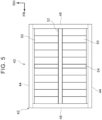
- the battery pack 40 has a rectangular box-shaped case 42 that accommodates a plurality of battery cells 50 arranged in the front and rear direction.
- the case 42 has a bottom wall (not shown) with a predetermined thickness, right and left side walls 44 with a predetermined thickness, a front wall 46 and a rear wall 48 with a predetermined thickness, and a top wall (not shown) with a predetermined thickness.
- At least a partition plate 52 and a partition plate 54 are integrally provided upright on the bottom wall of the case 42 with a predetermined height (a height close to the top wall).
- the partition plate 52 serves as a partition member with a predetermined thickness and extends in the front and rear direction at the central part in the vehicle width direction to partition right and left sides from each other.
- the partition plate 54 serves as a partition member with a predetermined thickness and extends in the vehicle width direction at substantially the central part of the partition plate 52 in the front and rear direction.
- the right and left side walls 44, the front wall 46, the rear wall 48, and the partition plates 52, 54 each have stiffness to such an extent as to be capable of withstanding fastening with the fasteners, for example, bolts
- the first frame 32 and the partition plate 52 are fastened (joined) to each other by fasteners, such as a plurality of (for example, four at predetermined intervals in the front and rear direction) bolts
- the second frame 34 and the partition plate 54 are fastened (joined) to each other by fasteners, for example, a plurality of (for example, two at predetermined intervals in the vehicle width direction) bolts.
- a front-side half of the first frame 32 on the front side with respect to the second frame 34 is fastened at two locations spaced at a predetermined interval in the front and rear direction
- a rear-side half of the first frame 32 on the rear side with respect to the second frame 34 is fastened at two locations spaced at a predetermined interval in the front and rear direction.
- An inner part of the second frame 34 in the vehicle width direction is fastened at two locations spaced at a predetermined interval in the vehicle width direction.
- An inner part of the first coupling portion 36 in the vehicle width direction, linearly formed in the vehicle width direction, and the front wall 46 are fastened (joined) to each other by fasteners, for example, a plurality of (for example, two at predetermined intervals in the vehicle width direction) bolts
- fasteners for example, a plurality of (for example, two at predetermined intervals in the vehicle width direction) bolts
- an inner part of the second coupling portion 38 in the vehicle width direction, linearly formed in the vehicle width direction, and the rear wall 48 are fastened (joined) to each other by fasteners, for example, a plurality of (for example, two at a predetermined interval in the vehicle width direction) bolts.
- the outer ends of the second frame 34 in the vehicle width direction (inner parts in the vehicle width direction with respect to the parts fastened to the side rails 14) and the right and left side walls 44 are respectively fastened (joined) to each other by fasteners, for example, a plurality of (for example, three at predetermined intervals in the front and rear direction) bolts. Therefore, as shown in FIG. 3 , a plurality of through-holes 32A is formed in the first frame 32, a plurality of through-holes 34A is formed in the second frame 34, a plurality of through-holes 36A is formed in the first coupling portion 36, and a plurality of through-holes 38A is formed in the second coupling portion 38.
- the sub-frame 30 including the first frame 32 extending in the front and rear direction at the central part of the vehicle body frame 20 in the vehicle width direction and the second frame 34 extending in the vehicle width direction at the central part of the first frame 32 in the front and rear direction is provided between the first cross member 24 and the second cross member 26 of the vehicle body frame 20.
- the battery pack 40 is supported by the sub-frame 30 from the lower side.
- a space between the first cross member 24 and the second cross member 26 of the vehicle body frame 20 is an area where a displacement due to a twist is extremely small. Therefore, when the sub-frame 30 is provided in the area and the battery pack 40 is supported by the sub-frame 30, a twist of the battery pack 40 is reduced even when the vehicle body frame 20 performs tramping to twist while, for example, the frame vehicle 12 is driving on a rough road, so it is possible to reduce concerns about breakage of the battery pack 40.
- FIG. 6 is a graph that shows comparison among twist displacements applied to the battery pack 40.
- the "twist displacement" shows the ratio of a distance along the up and down direction between the highest part and the lowest part in a case where the front end and the rear end of the case 42 rotate in mutually opposite directions (that is, twist) in a front view or a back view about an imaginary central axis extending in the front and rear direction at the central part in the vehicle width direction and the central part in the height direction of the battery pack 40 where a monocoque vehicle is "5".
- a twist displacement applied to the battery pack 40 supported by the battery mounting structure 10 according to the present embodiment is smaller than that in a case of the monocoque vehicle that is generally difficult to twist (smaller in twist displacement) than a frame vehicle (conventional one).
- the battery mounting structure 10 it is possible to ensure steering stability and also protect the battery pack 40 while the frame vehicle 12 is driving on a rough road.
- the sub-frame 30 just needs to be provided in the area (twist node) where a displacement due to a twist is extremely small in the vehicle body frame 20. Therefore, an enormous weight increase and an increase in manufacturing cost are also suppressed, so a reduction in weight and a reduction in cost are also achieved in the frame vehicle 12.
- the sub-frame 30 includes the first coupling portion 36 provided at the front end of the first frame 32 and extending in the vehicle width direction and the second coupling portion 38 provided at the rear end of the first frame 32 and extending in the vehicle width direction.
- the outer ends of the first coupling portion 36 in the vehicle width direction and the outer ends of the second frame 34 in the vehicle width direction are respectively fastened (joined) to the side rails 14 (including the flanges 14D and the projected parts 15), and the outer ends of the second coupling portion 38 in the vehicle width direction are fastened (joined) to the second cross member 26. Therefore, with the sub-frame 30, the battery pack 40 that is a heavy load can be stably supported.
- the battery pack 40 is fastened (joined) to the first frame 32, the second frame 34, the inner part of the first coupling portion 36 in the vehicle width direction, and the inner part of the second coupling portion 38 in the vehicle width direction (see the solid circle marks in FIG. 4 ).
- fastening portions (joint portions) of the battery pack 40 with the first frame 32, the second frame 34, the inner part of the first coupling portion 36 in the vehicle width direction, and the inner part of the second coupling portion 38 in the vehicle width direction are portions in the area where a displacement due to a twist is extremely small.
- the first frame 32 and the second frame 34 are located at the "twist node", and the fastening portions (joint portions) of the battery pack 40 with the first frame 32 and the second frame 34 are located in the area E where a displacement is further smaller in the area where a displacement due to a twist is extremely small. Therefore, even when the vehicle body frame 20 twists while, for example, the frame vehicle 12 is driving on a rough road, it is possible to further reduce concerns about breakage of the battery pack 40, so protection performance for the battery pack 40 is improved.
- the sub-frame 30 is provided on the upper side of the vehicle body frame 20. Therefore, the battery pack 40 can be significantly spaced apart from a road surface, so protection performance for the battery pack 40 is improved.
- the first frame 32 is higher in stiffness than the second frame 34. Therefore, even when the vehicle body frame 20 twists while, for example, the frame vehicle 12 is driving on a rough road, movement like a wave of the battery cells 50 accommodated so as to be arranged in the front and rear direction in the battery pack 40 (case 42) is reduced.
- the sub-frame 30 may be provided at an intermediate part of the vehicle body frame 20 in the up and down direction as in the case of a first modification shown in FIG. 7 . More specifically, each of the outer ends of the first coupling portion 36 in the vehicle width direction is fastened (joined) from the upper side to a flange 14E projecting inward in the vehicle width direction from the intermediate part in the up and down direction of an inner surface, facing inward in the vehicle width direction, of the front part 14A of a corresponding one of the side rails 14 by fasteners, for example, two bolts.
- each of the outer ends of the second coupling portion 38 in the vehicle width direction is fastened (joined) from the upper side to a flange 14F projecting inward in the vehicle width direction from the intermediate part in the up and down direction of an inner surface, facing inward in the vehicle width direction, of the rear part 14B of a corresponding one of the side rails 14 by fasteners, for example, two bolts.
- Each of the outer ends of the second frame 34 in the vehicle width direction is fastened (joined) from the upper side to a flange 14G projecting inward in the vehicle width direction from the intermediate part in the up and down direction of an inner surface, facing inward in the vehicle width direction, of the central part 14C of a corresponding one of the side rails 14 by fasteners, for example, three bolts.
- the sub-frame 30 does not project toward the upper side or the lower side beyond the vehicle body frame 20 (side rail 14) and is disposed on the inner side of the vehicle body frame 20. Therefore, a larger space can be taken in the up and down direction on the vehicle cabin side as compared to the case of the above-described embodiment by the amount by which the sub-frame 30 (battery pack 40) is moved to the lower side.
- the sub-frame 30 is moved to the lower side as compared to the case of the above-described embodiment, the battery pack 40 can be spaced apart from a road surface, so protection performance for the battery pack 40 is improved.
- each of the outer ends of the second coupling portion 38 in the vehicle width direction may be fastened (joined) from the lower side to a corresponding one of the outer ends of a lower surface of the second cross member 26 in the vehicle width direction by fasteners, for example, two bolts.
- fasteners for example, two bolts.
- the sub-frame 30 may be provided on the lower side of the vehicle body frame 20 as in the case of a second modification shown in FIG. 8 . More specifically, each of the outer ends of the first coupling portion 36 in the vehicle width direction is fastened (joined) from the lower side to a lower surface of the front part 14A of a corresponding one of the side rails 14 and a flange 14H projecting inward in the vehicle width direction from the lower surface by fasteners, for example, two bolts in total.
- Each of the outer ends of the second coupling portion 38 in the vehicle width direction is fastened (joined) from the lower side to a flange 14J projecting inward in the vehicle width direction from a lower surface of the rear part 14B of a corresponding one of the side rails 14 by fasteners, for example, two bolts in total.
- Each of the outer ends of the second frame 34 in the vehicle width direction is fastened (joined) from the lower side to a lower surface of the central part 14C of a corresponding one of the side rails 14 and a lower surface of a projected part 17 formed upside down from the projected part 15, by fasteners, for example, three bolts in total.
- the sub-frame 30 is disposed on the lower side of the vehicle body frame 20 (side rails 14), so the battery pack 40 is disposed on the inner side of the vehicle body frame 20.
- the battery pack 40 (case 42) at least partially overlaps the vehicle body frame 20 in the height direction, and the right and left side walls 44, the front wall 46, and the rear wall 48 of the battery pack 40 (case 42) are at least partially surrounded by the vehicle body frame 20 in the height direction.
- each of the outer ends of the second coupling portion 38 in the vehicle width direction may be fastened (joined) from the lower side to a corresponding one of the outer ends of a lower surface of the second cross member 26 in the vehicle width direction by fasteners, for example, two bolts.
- fasteners for example, two bolts.
- the sub-frame 30 is not limited to the one formed such that the first frame 32, the second frame 34, the first coupling portion 36, and the second coupling portion 38 are integrally joined to one another by welding or the like.
- the first frame 32, the second frame 34, the first coupling portion 36, and the second coupling portion 38 at least the first frame 32 and the second frame 34 may be integrally formed.
- the battery mounting structure 10 of the frame vehicle 12 according to the present embodiment has been described with reference to the drawings; however, the battery mounting structure 10 of the frame vehicle 12 according to the present embodiment is not limited to those shown in the drawings.
- the battery mounting structure 10 of the frame vehicle 12 according to the present embodiment may be changed in design without departing from the scope of the invention.
- the first frame 32 and the second frame 34 may be integrally formed by fastening, bonding, or the like, or the first frame 32 and both the first coupling portion 36 and the second coupling portion 38 may be integrally formed by fastening, bonding, or the like.
- the battery pack 40 may be fastened (joined) so as to be suspended from the sub-frame 30.
- the partition plates 52, 54 may be integrally suspended at a predetermined level (a level close to the bottom wall) from the top wall of the case 42.
- an under cover with higher strength than usual is preferably provided on the lower side of the battery pack 40 from the viewpoint of protecting the battery pack 40.
Landscapes
- Engineering & Computer Science (AREA)
- Chemical & Material Sciences (AREA)
- Combustion & Propulsion (AREA)
- Transportation (AREA)
- Mechanical Engineering (AREA)
- Aviation & Aerospace Engineering (AREA)
- Chemical Kinetics & Catalysis (AREA)
- Electrochemistry (AREA)
- General Chemical & Material Sciences (AREA)
- Body Structure For Vehicles (AREA)
- Arrangement Or Mounting Of Propulsion Units For Vehicles (AREA)
Abstract
A battery mounting structure (10) in a frame vehicle (12) includes: a vehicle body frame (20) including a pair of right and left side rails (14) extending in a vehicle front and rear direction, a first cross member (24) coupling vehicle front-side parts of the side rails (14) in a vehicle width direction, and a second cross member (26) coupling vehicle rear-side parts of the side rails (14) in the vehicle width direction; a sub-frame (30) including a first frame (32) extending in the vehicle front and rear direction at a central part of the vehicle body frame (20) in the vehicle width direction and a second frame (34) extending in the vehicle width direction at a central part of the first frame (32) in the vehicle front and rear direction, the sub-frame (30) being provided between the first cross member (24) and the second cross member (26); and a battery pack (40) supported on the sub-frame (30) from a vehicle lower side.
Description
- The invention relates to a battery mounting structure in a frame vehicle.
- A vehicle body structure of an electrified vehicle in which a plurality of cross members extending in a vehicle width direction is spanned between a pair of right and left frames extending in a front and rear direction and a battery pack is disposed on an upper side of the plurality of cross members is generally known (see, for example,
Japanese Unexamined Patent Application Publication No. 2018-144700 JP 2018-144700 A - Incidentally, a frame vehicle ensures steering stability while driving on a rough road, by a twist of a vehicle body frame that is a vehicle body framework. For this reason, if a battery pack in which a plurality of battery cells is arranged in the front and rear direction is accommodated in a case is mounted on such a frame vehicle, the plurality of battery cells may move like a wave or the case may be damaged due to a twist of the vehicle body frame. In other words, the battery pack may get broken.
- On the other hand, if the stiffness of the vehicle body frame is improved by providing the vehicle body frame with a reinforcement member to avoid breakage of the battery pack (to protect the battery pack), the vehicle body frame is difficult to twist, with the result that steering stability while driving on a rough road decreases. In this way, there is still room for improvement in a structure for ensuring steering stability and also protecting a battery pack while driving on a rough road in a frame vehicle.
- The invention provides a battery mounting structure in a frame vehicle, which ensures steering stability and also protects a battery pack while the frame vehicle is driving on a rough road.
- A first aspect of the invention provides a battery mounting structure in a frame vehicle. The battery mounting structure includes: a vehicle body frame including a pair of right and left side rails extending in a vehicle front and rear direction, a first cross member coupling vehicle front-side parts of the side rails in a vehicle width direction, and a second cross member coupling vehicle rear-side parts of the side rails in the vehicle width direction; a sub-frame including a first frame extending in the vehicle front and rear direction at a central part of the vehicle body frame in the vehicle width direction and a second frame extending in the vehicle width direction at a central part of the first frame in the vehicle front and rear direction, the sub-frame being provided between the first cross member and the second cross member; and a battery pack supported on the sub-frame from a vehicle lower side.
- According the first aspect, the sub-frame including the first frame extending in the vehicle front and rear direction at the central part of the vehicle body frame in the vehicle width direction and the second frame extending in the vehicle width direction at the central part of the first frame in the vehicle front and rear direction is provided between the first cross member and the second cross member of the vehicle body frame. The battery pack is supported on the sub-frame from the vehicle lower side.
- Here, a space between the first cross member and the second cross member of the vehicle body frame is an area where a displacement due to a twist is extremely small. Therefore, when the sub-frame is provided in that area and the battery pack is supported by the sub-frame, concerns about breakage of the battery pack are reduced even when the vehicle body frame twists while, for example, the frame vehicle is driving on a rough road. In other words, according to the first aspect of the invention, steering stability is ensured and also the battery pack is protected while the frame vehicle is driving on a rough road. The "central part in the vehicle front and rear direction" in the first aspect of the invention also includes a "substantially central part in the vehicle front and rear direction" slightly shifted in the vehicle front and rear direction from the central part in the vehicle front and rear direction.
- In a battery mounting structure in a frame vehicle according to a second aspect of the invention, in addition to the battery mounting structure in a frame vehicle according to the first aspect, the sub-frame may include a first coupling portion provided at a vehicle front-side end of the first frame and extending in the vehicle width direction, and a second coupling portion provided at a vehicle rear-side end of the first frame and extending in the vehicle width direction, and outer ends of the first coupling portion in the vehicle width direction and outer ends of the second frame in the vehicle width direction may be respectively joined to the side rails, and outer ends of the second coupling portion in the vehicle width direction may be joined to the second cross member.
- According to the second aspect, the sub-frame includes the first coupling portion provided at the vehicle front-side end of the first frame and extending in the vehicle width direction and the second coupling portion provided at the vehicle rear-side end of the first frame and extending in the vehicle width direction. The outer ends of the first coupling portion in the vehicle width direction and the outer ends of the second frame in the vehicle width direction are respectively joined to the side rails, and the outer ends of the second coupling portion in the vehicle width direction are joined to the second cross member. Therefore, the battery pack that is a heavy load is stably supported by the sub-frame.
- In a battery mounting structure in a frame vehicle according to a third aspect of the invention, in addition to the battery mounting structure in a frame vehicle according to the second aspect, the battery pack may be joined to the first frame, the second frame, an inner part of the first coupling portion in the vehicle width direction, and an inner part of the second coupling portion in the vehicle width direction.
- According to the third aspect, the battery pack is joined to the first frame, the second frame, the inner part of the first coupling portion in the vehicle width direction, and the inner part of the second coupling portion in the vehicle width direction. Here, joint portions of the battery pack with the first frame, the second frame, the inner part of the first coupling portion in the vehicle width direction, and the inner part of the second coupling portion in the vehicle width direction are portions in the area in which a displacement due to a twist is extremely small. Therefore, even when the vehicle body frame twists, concerns about breakage of the battery pack are further reduced, and protection performance for the battery pack is improved.
- In a battery mounting structure in a frame vehicle according to a fourth aspect of the invention, in addition to the battery mounting structure in a frame vehicle according to any one of the first to third aspects, the sub-frame may be provided on a vehicle upper side of the vehicle body frame.
- According to the fourth aspect, the sub-frame is provided on the vehicle upper side of the vehicle body frame. Therefore, the battery pack is significantly spaced apart from a road surface, so protection performance for the battery pack is improved.
- In a battery mounting structure in a frame vehicle according to a fifth aspect of the invention, in addition to the battery mounting structure in a frame vehicle according to any one of the first to third aspects, the sub-frame may be provided at an intermediate part of the vehicle body frame in a vehicle up and down direction.
- According to the fifth aspect, the sub-frame is provided at the intermediate part of the vehicle body frame in the vehicle up and down direction. Therefore, a vehicle cabin space increases, and the battery pack is spaced apart from a road surface, so protection performance for the battery pack is improved.
- In a battery mounting structure in a frame vehicle according to a sixth aspect of the invention, in addition to the battery mounting structure in a frame vehicle according to any one of the first to third aspects, the sub-frame may be provided on a vehicle lower side of the vehicle body frame.
- According to the sixth aspect, the sub-frame is provided on the vehicle lower side of the vehicle body frame. Therefore, the battery pack is disposed on an inner side of the vehicle body frame. Thus, mounting stability of the battery pack is improved, and protection performance for the battery pack in the event of a collision of the frame vehicle is improved.
- In a battery mounting structure in a frame vehicle according to a seventh aspect of the invention, in addition to the battery mounting structure in a frame vehicle according to any one of the first to sixth aspects, the first frame may be higher in stiffness than the second frame.
- According to the seventh aspect, the first frame is higher in stiffness than the second frame. Therefore, even when the vehicle body frame twists while, for example, the frame vehicle is driving on a rough road, movement like a wave of a plurality of battery cells accommodated in the battery pack so as to be arranged in the vehicle front and rear direction is reduced.
- In a battery mounting structure in a frame vehicle according to an eighth aspect of the invention, in addition to the battery mounting structure in a frame vehicle according to any one of the second to sixth aspects, at least the first frame and the second frame of the sub-frame may be integrally formed.
- According to the eighth aspect, at least the first frame and the second frame of the sub-frame are integrally formed. Therefore, in comparison with a case where the first frame and the second frame are not integrally formed, formability of the sub-frame is improved, and the number of components is reduced.
- As described above, according to the aspects of the invention, it is possible to ensure steering stability and also protect the battery pack while the frame vehicle is driving on a rough road.
- Features, advantages, and technical and industrial significance of exemplary embodiments of the invention will be described below with reference to the accompanying drawings, in which like signs denote like elements, and wherein:
-
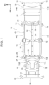
FIG. 1 is a schematic plan view of a battery mounting structure in a frame vehicle according to an embodiment; -
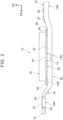
FIG. 2 is a schematic side view of the battery mounting structure in the frame vehicle according to the embodiment; -
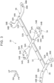
FIG. 3 is a schematic perspective view of a sub-frame that is a component of the battery mounting structure in the frame vehicle according to the embodiment; -
FIG. 4 is a schematic enlarged plan view of fastening points of the sub-frame that is a component of the battery mounting structure in the frame vehicle according to the embodiment; -
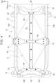
FIG. 5 is a schematic plan view of the internal structure of a battery pack supported by the battery mounting structure in the frame vehicle according to the embodiment; -
FIG. 6 is a graph that shows a twist displacement of the battery pack, caused by the battery mounting structure in the frame vehicle according to the embodiment; -
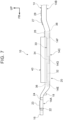
FIG. 7 is a schematic side view of a battery mounting structure in a frame vehicle according to a first modification of the embodiment; and -
FIG. 8 is a schematic side view of a battery mounting structure in a frame vehicle according to a second modification of the embodiment. - An embodiment according to the invention will be described in detail with reference to the accompanying drawings. For the sake of convenience of description, the arrow UP indicates a vehicle upward direction, the arrow FR indicates a vehicle forward direction, and the arrow RH indicates a direction to a vehicle right-hand side, shown as needed in the drawings. In the following description, when upper and lower, front and rear, and right and left directions are mentioned unless otherwise specified, these are assumed to indicate upper and lower sides in a vehicle up and down direction, front and rear sides in a vehicle front and rear direction, and right and left sides in a vehicle right and left direction (vehicle width direction).
- As shown in
FIG. 1 , aframe vehicle 12 including abattery mounting structure 10 according to the present embodiment is mainly a battery electric vehicle (BEV) or a fuel cell electric vehicle (FCEV). Theframe vehicle 12 includes a pair of right andleft side rails 14 disposed on both sides in the vehicle width direction and extending in the front and rear direction. Each of theside rails 14 is formed in a closed cross-sectional shape in a cross section taken along the vehicle width direction. A front wheel (not shown) and a rear wheel (not shown) are respectively disposed on an outer side of afront part 14A and an outer side of arear part 14B of each of theside rails 14 in the vehicle width direction. - As shown in
FIG. 2 , suspension units and the like (not shown) are disposed on a lower side of thefront part 14A and a lower side of therear part 14B of each of theside rails 14, so, in a side view in the vehicle width direction, thefront part 14A and therear part 14B of each of theside rails 14 are disposed on an upper side with respect to acentral part 14C of theside rail 14. In other words, thefront part 14A and therear part 14B of each of the side rails 14 respectively have inclined parts respectively inclined from thecentral part 14C toward a front upper side and a rear upper side and respectively extend from the inclined parts toward a front side and a rear side. - A
front bumper reinforcement 16 extending along substantially the vehicle width direction is spanned at front ends of the side rails 14 (see alsoFIG. 1 ). A rear bumper reinforcement (not shown) extending along substantially the vehicle width direction is spanned at rear ends of the side rails 14. Energy absorbing members, such as crush boxes (not shown), may be respectively provided between thefront bumper reinforcement 16 and the front end of each of the side rails 14 and between the rear bumper reinforcement and the rear end of each of the side rails 14. - As shown in
FIG. 1 , a plurality of cross members extending in the vehicle width direction is spanned between the side rails 14 between thefront bumper reinforcement 16 and the rear bumper reinforcement. More specifically,cross members front parts 14A of the side rails 14 to each other are spanned at thefront parts 14A, and threecross members rear parts 14B of the side rails 14 to each other are spanned at therear parts 14B. - The
cross members cross members vehicle body frame 20 is made up of thecross members cross members - In the following description, of the
cross members front parts 14A of the side rails 14 to each other, therearmost cross member 24 is referred to as "first cross member 24", and, of the threecross members rear parts 14B of the side rails 14 to each other, thefrontmost cross member 26 is referred to as "second cross member 26". - The
first cross member 24 and thecross member 23 on the front side of thefirst cross member 24 will support a front wheel motor (not shown) via a motor mount. Thesecond cross member 26 and thecross member 27 on the rear side of thecross member 26 will support a rear wheel motor (not shown) via a motor mount. A cab (body) (not shown) will be attached to each of the side rails 14, and a plurality of connectingportions 18 therefor is provided on an outer surface of each of the side rails 14. - In the
frame vehicle 12 including thevehicle body frame 20 as described above, thebattery pack 40 will be mounted at a central part (between front and rear axles) of thevehicle body frame 20 in the front and rear direction. Next, thebattery mounting structure 10 that supports thebattery pack 40 will be described in detail. InFIG. 2 , andFIG. 7 andFIG. 8 (described later), the connectingportions 18 at thecentral part 14C and therear part 14B of theside rail 14 and fasteners, for example, bolts, are not shown. - As shown in
FIG. 1 andFIG. 2 , asub-frame 30 made of high-tensile steel or the like is provided on the upper side of thevehicle body frame 20 between thefirst cross member 24 and thesecond cross member 26. As shown inFIG. 3 , thesub-frame 30 includes afirst frame 32 extending in the front and rear direction at the central part of thevehicle body frame 20 in the vehicle width direction and asecond frame 34 extending in the vehicle width direction at substantially the central part of thefirst frame 32 in the front and rear direction. - In other words, the
first frame 32 and thesecond frame 34 of thesub-frame 30 are formed in substantially a cross shape in a plan view, and thefirst frame 32 and thesecond frame 34 are integrally joined to each other by welding or the like. Thefirst frame 32 is configured to be higher in stiffness than thesecond frame 34. Specifically, for example, thefirst frame 32 is formed to be thicker in thickness than thesecond frame 34 and formed in a hat shape in cross section. - As shown in
FIG. 1 andFIG. 3 , thesub-frame 30 includes afirst coupling portion 36 extending in substantially the vehicle width direction and asecond coupling portion 38 extending in substantially the vehicle width direction. Thefirst coupling portion 36 is provided such that a central part of thefirst coupling portion 36 in the vehicle width direction is integrally joined by welding or the like to a front end (front-side end) of thefirst frame 32. Thesecond coupling portion 38 is provided such that a central part of thesecond coupling portion 38 in the vehicle width direction is integrally joined by welding or the like to a rear end (rear-side end) of thefirst frame 32. - The
first coupling portion 36 is formed in substantially a curved shape that is convex toward the rear side in a plan view. More specifically, thefirst coupling portion 36 is formed in such a shape that thefirst coupling portion 36 is linearly extended by a predetermined length outward in the vehicle width direction from the central part in the vehicle width direction and then linearly extended by a predetermined length forward and outward in the vehicle width direction from outer ends of the linearly extended part in the vehicle width direction. - Similarly, the
second coupling portion 38 is formed in substantially a curved shape that is convex toward the front side in a plan view. More specifically, thesecond coupling portion 38 is formed in such a shape (substantially a C shape in a plan view) that thesecond coupling portion 38 is linearly extended by a predetermined length outward in the vehicle width direction from the central part in the vehicle width direction, linearly extended by a predetermined length rearward and outward in the vehicle width direction from outer ends of the linearly extended part in the vehicle width direction, and linearly extended by a predetermined length rearward from outer ends of the linearly extended parts in the vehicle width direction. - As indicated by the outline circle marks in
FIG. 1 andFIG. 4 , the outer ends of thefirst coupling portion 36 in the vehicle width direction each are fastened (joined) to an upper surface of thefront part 14A of a corresponding one of the side rails 14 and an upper surface of aflange 14D projecting inward from the upper surface in the vehicle width direction by fasteners, for example, two bolts in total, from the upper side. The outer ends of thesecond coupling portion 38 in the vehicle width direction each are fastened (joined) to an outer end on an upper surface of thesecond cross member 26 in the vehicle width direction by fasteners, for example, two bolts arranged in the front and rear direction, from the upper side. - The outer ends of the
second frame 34 in the vehicle width direction each are fastened (joined) to an upper surface of thecentral part 14C of a corresponding one of the side rails 14 and an upper surface of a projected part 15 (see alsoFIG. 2 ) integrally provided so as to project outward from an outer surface of thecentral part 14C in the vehicle width direction by fasteners, for example, three bolts in total (one for the projectedpart 15 and one for each of the front and rear sides of the side rail 14) from the upper side. Therefore, as shown inFIG. 3 , a plurality of through-holes 34B is formed in thesecond frame 34, a plurality of through-holes 36B is formed in thefirst coupling portion 36, and a plurality of through-holes 38B is formed in thesecond coupling portion 38. - Here, an area between the
first cross member 24 and the second cross member 26 (the front end of thesecond cross member 26 can be included) in thevehicle body frame 20 is an area in which, when theframe vehicle 12 drives on a rough road, a twist that occurs in thevehicle body frame 20 is extremely small. Particularly, the central part in the vehicle width direction and substantially the central part in the front and rear direction between thefirst cross member 24 and thesecond cross member 26 correspond to a "twist node" where a displacement due to a twist is zero. - In other words, the
sub-frame 30 is provided in the area where a displacement due to a twist is extremely small in thevehicle body frame 20, and thefirst frame 32 and thesecond frame 34 are disposed at the "twist node". In the following description, an area (indicated by an imaginary line inFIG. 4 ) in substantially a rhombus shape in a plan view, obtained by connecting a central part in the front and rear direction at the central part of thefirst coupling portion 36 in the vehicle width direction, a central part in the front and rear direction at the central part of thesecond coupling portion 38 in the vehicle width direction, and the outer ends of thesecond frame 34 in the vehicle width direction, is referred to as "area E". - The area E is an area where a displacement is further smaller in the area where a displacement due to a twist is extremely small in the
vehicle body frame 20. The fasteners, for example, bolts (through-holes 34B), that fasten the outer ends of thesecond frame 34 in the vehicle width direction to the projectedparts 15 and the side rails 14 are located on the imaginary line that defines the area E (seeFIG. 4 ). - The reason why the
second frame 34 is placed at substantially the central part in the front and rear direction between thefirst cross member 24 and thesecond cross member 26 is because the "twist node" can slightly shifts forward or rearward from the central part in the front and rear direction between thefirst cross member 24 and thesecond cross member 26 depending on the shape of thevehicle body frame 20 and this case is included. - The
battery pack 40 is supported by thesub-frame 30 from the lower side (inFIG. 1 andFIG. 4 , thebattery pack 40 is indicated by the imaginary line). More specifically, thebattery pack 40 is fastened (joined) to thefirst frame 32, thesecond frame 34, the inner part of thefirst coupling portion 36 in the vehicle width direction, and the inner part of thesecond coupling portion 38 in the vehicle width direction. Here, the configuration of thebattery pack 40 will be described. As shown inFIG. 5 , thebattery pack 40 has a rectangular box-shapedcase 42 that accommodates a plurality ofbattery cells 50 arranged in the front and rear direction. - The
case 42 has a bottom wall (not shown) with a predetermined thickness, right and leftside walls 44 with a predetermined thickness, afront wall 46 and arear wall 48 with a predetermined thickness, and a top wall (not shown) with a predetermined thickness. At least apartition plate 52 and apartition plate 54 are integrally provided upright on the bottom wall of thecase 42 with a predetermined height (a height close to the top wall). Thepartition plate 52 serves as a partition member with a predetermined thickness and extends in the front and rear direction at the central part in the vehicle width direction to partition right and left sides from each other. Thepartition plate 54 serves as a partition member with a predetermined thickness and extends in the vehicle width direction at substantially the central part of thepartition plate 52 in the front and rear direction. In other words, the right and leftside walls 44, thefront wall 46, therear wall 48, and thepartition plates - Therefore, as indicated by the solid circle marks in
FIG. 1 andFIG. 4 , thefirst frame 32 and thepartition plate 52 are fastened (joined) to each other by fasteners, such as a plurality of (for example, four at predetermined intervals in the front and rear direction) bolts, and thesecond frame 34 and thepartition plate 54 are fastened (joined) to each other by fasteners, for example, a plurality of (for example, two at predetermined intervals in the vehicle width direction) bolts. - More specifically, a front-side half of the
first frame 32 on the front side with respect to thesecond frame 34 is fastened at two locations spaced at a predetermined interval in the front and rear direction, and a rear-side half of thefirst frame 32 on the rear side with respect to thesecond frame 34 is fastened at two locations spaced at a predetermined interval in the front and rear direction. An inner part of thesecond frame 34 in the vehicle width direction is fastened at two locations spaced at a predetermined interval in the vehicle width direction. - An inner part of the
first coupling portion 36 in the vehicle width direction, linearly formed in the vehicle width direction, and thefront wall 46 are fastened (joined) to each other by fasteners, for example, a plurality of (for example, two at predetermined intervals in the vehicle width direction) bolts, and an inner part of thesecond coupling portion 38 in the vehicle width direction, linearly formed in the vehicle width direction, and therear wall 48 are fastened (joined) to each other by fasteners, for example, a plurality of (for example, two at a predetermined interval in the vehicle width direction) bolts. - The outer ends of the
second frame 34 in the vehicle width direction (inner parts in the vehicle width direction with respect to the parts fastened to the side rails 14) and the right and leftside walls 44 are respectively fastened (joined) to each other by fasteners, for example, a plurality of (for example, three at predetermined intervals in the front and rear direction) bolts. Therefore, as shown inFIG. 3 , a plurality of through-holes 32A is formed in thefirst frame 32, a plurality of through-holes 34A is formed in thesecond frame 34, a plurality of through-holes 36A is formed in thefirst coupling portion 36, and a plurality of through-holes 38A is formed in thesecond coupling portion 38. - Next, the operation of the thus configured
battery mounting structure 10 in theframe vehicle 12 according to the present embodiment will be described. - As described above, the
sub-frame 30 including thefirst frame 32 extending in the front and rear direction at the central part of thevehicle body frame 20 in the vehicle width direction and thesecond frame 34 extending in the vehicle width direction at the central part of thefirst frame 32 in the front and rear direction is provided between thefirst cross member 24 and thesecond cross member 26 of thevehicle body frame 20. Thebattery pack 40 is supported by thesub-frame 30 from the lower side. - Here, a space between the
first cross member 24 and thesecond cross member 26 of thevehicle body frame 20 is an area where a displacement due to a twist is extremely small. Therefore, when thesub-frame 30 is provided in the area and thebattery pack 40 is supported by thesub-frame 30, a twist of thebattery pack 40 is reduced even when thevehicle body frame 20 performs tramping to twist while, for example, theframe vehicle 12 is driving on a rough road, so it is possible to reduce concerns about breakage of thebattery pack 40. -
FIG. 6 is a graph that shows comparison among twist displacements applied to thebattery pack 40. The "twist displacement" shows the ratio of a distance along the up and down direction between the highest part and the lowest part in a case where the front end and the rear end of thecase 42 rotate in mutually opposite directions (that is, twist) in a front view or a back view about an imaginary central axis extending in the front and rear direction at the central part in the vehicle width direction and the central part in the height direction of thebattery pack 40 where a monocoque vehicle is "5". As shown inFIG. 6 , a twist displacement applied to thebattery pack 40 supported by thebattery mounting structure 10 according to the present embodiment is smaller than that in a case of the monocoque vehicle that is generally difficult to twist (smaller in twist displacement) than a frame vehicle (conventional one). - In this way, with the
battery mounting structure 10 according to the present embodiment, it is possible to ensure steering stability and also protect thebattery pack 40 while theframe vehicle 12 is driving on a rough road. Moreover, with thebattery mounting structure 10 according to the present embodiment, thesub-frame 30 just needs to be provided in the area (twist node) where a displacement due to a twist is extremely small in thevehicle body frame 20. Therefore, an enormous weight increase and an increase in manufacturing cost are also suppressed, so a reduction in weight and a reduction in cost are also achieved in theframe vehicle 12. - The
sub-frame 30 includes thefirst coupling portion 36 provided at the front end of thefirst frame 32 and extending in the vehicle width direction and thesecond coupling portion 38 provided at the rear end of thefirst frame 32 and extending in the vehicle width direction. The outer ends of thefirst coupling portion 36 in the vehicle width direction and the outer ends of thesecond frame 34 in the vehicle width direction are respectively fastened (joined) to the side rails 14 (including theflanges 14D and the projected parts 15), and the outer ends of thesecond coupling portion 38 in the vehicle width direction are fastened (joined) to thesecond cross member 26. Therefore, with thesub-frame 30, thebattery pack 40 that is a heavy load can be stably supported. - The
battery pack 40 is fastened (joined) to thefirst frame 32, thesecond frame 34, the inner part of thefirst coupling portion 36 in the vehicle width direction, and the inner part of thesecond coupling portion 38 in the vehicle width direction (see the solid circle marks inFIG. 4 ). Here, fastening portions (joint portions) of thebattery pack 40 with thefirst frame 32, thesecond frame 34, the inner part of thefirst coupling portion 36 in the vehicle width direction, and the inner part of thesecond coupling portion 38 in the vehicle width direction are portions in the area where a displacement due to a twist is extremely small. - Particularly, the
first frame 32 and thesecond frame 34 are located at the "twist node", and the fastening portions (joint portions) of thebattery pack 40 with thefirst frame 32 and thesecond frame 34 are located in the area E where a displacement is further smaller in the area where a displacement due to a twist is extremely small. Therefore, even when thevehicle body frame 20 twists while, for example, theframe vehicle 12 is driving on a rough road, it is possible to further reduce concerns about breakage of thebattery pack 40, so protection performance for thebattery pack 40 is improved. - The
sub-frame 30 is provided on the upper side of thevehicle body frame 20. Therefore, thebattery pack 40 can be significantly spaced apart from a road surface, so protection performance for thebattery pack 40 is improved. Thefirst frame 32 is higher in stiffness than thesecond frame 34. Therefore, even when thevehicle body frame 20 twists while, for example, theframe vehicle 12 is driving on a rough road, movement like a wave of thebattery cells 50 accommodated so as to be arranged in the front and rear direction in the battery pack 40 (case 42) is reduced. - The operation of the
battery mounting structure 10 according to the present embodiment is as described above. Alternatively, thesub-frame 30 may be provided at an intermediate part of thevehicle body frame 20 in the up and down direction as in the case of a first modification shown inFIG. 7 . More specifically, each of the outer ends of thefirst coupling portion 36 in the vehicle width direction is fastened (joined) from the upper side to aflange 14E projecting inward in the vehicle width direction from the intermediate part in the up and down direction of an inner surface, facing inward in the vehicle width direction, of thefront part 14A of a corresponding one of the side rails 14 by fasteners, for example, two bolts. - Similarly, each of the outer ends of the
second coupling portion 38 in the vehicle width direction is fastened (joined) from the upper side to aflange 14F projecting inward in the vehicle width direction from the intermediate part in the up and down direction of an inner surface, facing inward in the vehicle width direction, of therear part 14B of a corresponding one of the side rails 14 by fasteners, for example, two bolts. Each of the outer ends of thesecond frame 34 in the vehicle width direction is fastened (joined) from the upper side to aflange 14G projecting inward in the vehicle width direction from the intermediate part in the up and down direction of an inner surface, facing inward in the vehicle width direction, of thecentral part 14C of a corresponding one of the side rails 14 by fasteners, for example, three bolts. - Thus, in a side view, the
sub-frame 30 does not project toward the upper side or the lower side beyond the vehicle body frame 20 (side rail 14) and is disposed on the inner side of thevehicle body frame 20. Therefore, a larger space can be taken in the up and down direction on the vehicle cabin side as compared to the case of the above-described embodiment by the amount by which the sub-frame 30 (battery pack 40) is moved to the lower side. Although thesub-frame 30 is moved to the lower side as compared to the case of the above-described embodiment, thebattery pack 40 can be spaced apart from a road surface, so protection performance for thebattery pack 40 is improved. - Although not shown in the drawing, when the
second cross member 26 is formed in a closed cross-sectional shape, each of the outer ends of thesecond coupling portion 38 in the vehicle width direction may be fastened (joined) from the lower side to a corresponding one of the outer ends of a lower surface of thesecond cross member 26 in the vehicle width direction by fasteners, for example, two bolts. At this time, when the level of the lower surface of thesecond cross member 26 is not an appropriate level, the level of thesecond cross member 26 may be changed as needed. - The
sub-frame 30 may be provided on the lower side of thevehicle body frame 20 as in the case of a second modification shown inFIG. 8 . More specifically, each of the outer ends of thefirst coupling portion 36 in the vehicle width direction is fastened (joined) from the lower side to a lower surface of thefront part 14A of a corresponding one of the side rails 14 and aflange 14H projecting inward in the vehicle width direction from the lower surface by fasteners, for example, two bolts in total. - Each of the outer ends of the
second coupling portion 38 in the vehicle width direction is fastened (joined) from the lower side to aflange 14J projecting inward in the vehicle width direction from a lower surface of therear part 14B of a corresponding one of the side rails 14 by fasteners, for example, two bolts in total. Each of the outer ends of thesecond frame 34 in the vehicle width direction is fastened (joined) from the lower side to a lower surface of thecentral part 14C of a corresponding one of the side rails 14 and a lower surface of a projectedpart 17 formed upside down from the projectedpart 15, by fasteners, for example, three bolts in total. - Thus, in a side view, the
sub-frame 30 is disposed on the lower side of the vehicle body frame 20 (side rails 14), so thebattery pack 40 is disposed on the inner side of thevehicle body frame 20. In other words, in a side view, the battery pack 40 (case 42) at least partially overlaps thevehicle body frame 20 in the height direction, and the right and leftside walls 44, thefront wall 46, and therear wall 48 of the battery pack 40 (case 42) are at least partially surrounded by thevehicle body frame 20 in the height direction. - Therefore, it is possible to improve mounting stability of the
battery pack 40, and it is also possible to improve protection performance for thebattery pack 40 in the event of a collision of theframe vehicle 12. In other words, even when a collision load is input to theframe vehicle 12 in the front and rear direction or in the vehicle width direction, it is possible to further effectively protect thebattery pack 40 from the collision load. - Although not shown in the drawing as in the case of the above, when the
second cross member 26 is formed in a closed cross-sectional shape, each of the outer ends of thesecond coupling portion 38 in the vehicle width direction may be fastened (joined) from the lower side to a corresponding one of the outer ends of a lower surface of thesecond cross member 26 in the vehicle width direction by fasteners, for example, two bolts. At this time, when the level of the lower surface of thesecond cross member 26 is not an appropriate level, the level of thesecond cross member 26 may be changed as needed. - The
sub-frame 30 is not limited to the one formed such that thefirst frame 32, thesecond frame 34, thefirst coupling portion 36, and thesecond coupling portion 38 are integrally joined to one another by welding or the like. Of thefirst frame 32, thesecond frame 34, thefirst coupling portion 36, and thesecond coupling portion 38, at least thefirst frame 32 and thesecond frame 34 may be integrally formed. With this configuration, in comparison with a case where thefirst frame 32 and thesecond frame 34 are not integrally formed, formability (dimensional accuracy) of thesub-frame 30 is improved, and the number of components can be reduced. - The
battery mounting structure 10 of theframe vehicle 12 according to the present embodiment has been described with reference to the drawings; however, thebattery mounting structure 10 of theframe vehicle 12 according to the present embodiment is not limited to those shown in the drawings. Thebattery mounting structure 10 of theframe vehicle 12 according to the present embodiment may be changed in design without departing from the scope of the invention. For example, in thesub-frame 30, thefirst frame 32 and thesecond frame 34 may be integrally formed by fastening, bonding, or the like, or thefirst frame 32 and both thefirst coupling portion 36 and thesecond coupling portion 38 may be integrally formed by fastening, bonding, or the like. - Although not shown in the drawing, the
battery pack 40 may be fastened (joined) so as to be suspended from thesub-frame 30. In this case, thepartition plates case 42. In this case, an under cover with higher strength than usual is preferably provided on the lower side of thebattery pack 40 from the viewpoint of protecting thebattery pack 40.
Claims (8)
- A battery mounting structure (10) in a frame vehicle (12), the battery mounting structure (10) comprising:a vehicle body frame (20) including a pair of right and left side rails (14) extending in a vehicle front and rear direction, a first cross member (24) coupling vehicle front-side parts of the side rails (14) to each other in a vehicle width direction, and a second cross member (26) coupling vehicle rear-side parts of the side rails (14) to each other in the vehicle width direction;a sub-frame (30) including a first frame (32) extending in the vehicle front and rear direction at a central part of the vehicle body frame (20) in the vehicle width direction and a second frame (34) extending in the vehicle width direction at a central part of the first frame (32) in the vehicle front and rear direction, the sub-frame (30) being provided between the first cross member (24) and the second cross member (26); anda battery pack (40) supported on the sub-frame (30) from a vehicle lower side.
- The battery mounting structure (10) according to claim 1, wherein:the sub-frame (30) includesa first coupling portion (36) provided at a vehicle front-side end of the first frame (32) and extending in the vehicle width direction, anda second coupling portion (38) provided at a vehicle rear-side end of the first frame (32) and extending in the vehicle width direction; andouter ends of the first coupling portion (36) in the vehicle width direction and outer ends of the second frame (34) in the vehicle width direction are joined to the side rails (14), and outer ends of the second coupling portion (38) in the vehicle width direction are joined to the second cross member (26).
- The battery mounting structure (10) according to claim 2, wherein the battery pack (40) is joined to the first frame (32), the second frame (34), an inner part of the first coupling portion (36) in the vehicle width direction, and an inner part of the second coupling portion (38) in the vehicle width direction.
- The battery mounting structure (10) according to claim 3, wherein the sub-frame (30) is provided on a vehicle upper side of the vehicle body frame (20).
- The battery mounting structure (10) according to claim 3, wherein the sub-frame (30) is provided at an intermediate part of the vehicle body frame (20) in a vehicle up and down direction.
- The battery mounting structure (10) according to claim 3, wherein the sub-frame (30) is provided on a vehicle lower side of the vehicle body frame (20).
- The battery mounting structure (10) according to any one of claims 1 to 6, wherein the first frame (32) is higher in stiffness than the second frame (34).
- The battery mounting structure (10) according to any one of claims 2 to 6, wherein at least the first frame (32) and the second frame (34) of the sub-frame (30) are integrally formed.
Applications Claiming Priority (1)
| Application Number | Priority Date | Filing Date | Title |
|---|---|---|---|
| JP2023206486A JP2025091298A (en) | 2023-12-06 | 2023-12-06 | Battery mounting structure for frame vehicles |
Publications (1)
| Publication Number | Publication Date |
|---|---|
| EP4566860A1 true EP4566860A1 (en) | 2025-06-11 |
Family
ID=93840630
Family Applications (1)
| Application Number | Title | Priority Date | Filing Date |
|---|---|---|---|
| EP24217787.1A Pending EP4566860A1 (en) | 2023-12-06 | 2024-12-05 | Battery mounting structure in frame vehicle |
Country Status (5)
| Country | Link |
|---|---|
| US (1) | US20250178424A1 (en) |
| EP (1) | EP4566860A1 (en) |
| JP (1) | JP2025091298A (en) |
| KR (1) | KR20250086522A (en) |
| CN (1) | CN120096303A (en) |
Citations (6)
| Publication number | Priority date | Publication date | Assignee | Title |
|---|---|---|---|---|
| JP2018144700A (en) | 2017-03-07 | 2018-09-20 | 三菱自動車工業株式会社 | Body structure of electric vehicle |
| CN208325383U (en) * | 2018-06-27 | 2019-01-04 | 江铃汽车股份有限公司 | A kind of raising vehicle body side rigidity Battery case |
| US11077745B2 (en) * | 2019-07-30 | 2021-08-03 | Hyundai Motor Company | High voltage battery carrier for vehicle |
| US20210291636A1 (en) * | 2018-09-04 | 2021-09-23 | Ford Global Technologies, Llc | High voltage battery pack support and isolation for electrified vehicles |
| US11548361B2 (en) * | 2020-02-12 | 2023-01-10 | Ford Global Technologies, Llc | Support structures for vehicle frame mounted battery packs |
| DE102022123162B3 (en) * | 2022-09-12 | 2023-08-31 | Trailer Dynamics Gmbh | Commercial vehicle with battery box |
Family Cites Families (5)
| Publication number | Priority date | Publication date | Assignee | Title |
|---|---|---|---|---|
| JP3324182B2 (en) * | 1993-03-12 | 2002-09-17 | 日産自動車株式会社 | Electric vehicle battery mounting frame fastening structure |
| JP6520808B2 (en) * | 2016-04-21 | 2019-05-29 | トヨタ自動車株式会社 | Vehicle battery mounting structure |
| JP6922750B2 (en) * | 2018-01-12 | 2021-08-18 | トヨタ自動車株式会社 | Power storage device |
| JP6984494B2 (en) * | 2018-03-07 | 2021-12-22 | トヨタ自動車株式会社 | Body structure |
| KR102281166B1 (en) * | 2019-09-25 | 2021-07-26 | 주식회사 호원 | Battery case for electric vehicle |
-
2023
- 2023-12-06 JP JP2023206486A patent/JP2025091298A/en active Pending
-
2024
- 2024-12-03 KR KR1020240177265A patent/KR20250086522A/en active Pending
- 2024-12-04 CN CN202411767190.XA patent/CN120096303A/en active Pending
- 2024-12-05 US US18/970,173 patent/US20250178424A1/en active Pending
- 2024-12-05 EP EP24217787.1A patent/EP4566860A1/en active Pending
Patent Citations (6)
| Publication number | Priority date | Publication date | Assignee | Title |
|---|---|---|---|---|
| JP2018144700A (en) | 2017-03-07 | 2018-09-20 | 三菱自動車工業株式会社 | Body structure of electric vehicle |
| CN208325383U (en) * | 2018-06-27 | 2019-01-04 | 江铃汽车股份有限公司 | A kind of raising vehicle body side rigidity Battery case |
| US20210291636A1 (en) * | 2018-09-04 | 2021-09-23 | Ford Global Technologies, Llc | High voltage battery pack support and isolation for electrified vehicles |
| US11077745B2 (en) * | 2019-07-30 | 2021-08-03 | Hyundai Motor Company | High voltage battery carrier for vehicle |
| US11548361B2 (en) * | 2020-02-12 | 2023-01-10 | Ford Global Technologies, Llc | Support structures for vehicle frame mounted battery packs |
| DE102022123162B3 (en) * | 2022-09-12 | 2023-08-31 | Trailer Dynamics Gmbh | Commercial vehicle with battery box |
Also Published As
| Publication number | Publication date |
|---|---|
| KR20250086522A (en) | 2025-06-13 |
| JP2025091298A (en) | 2025-06-18 |
| US20250178424A1 (en) | 2025-06-05 |
| CN120096303A (en) | 2025-06-06 |
Similar Documents
| Publication | Publication Date | Title |
|---|---|---|
| JP7627344B2 (en) | Electric car body | |
| EP2617628B1 (en) | Structure of front section of vehicle body | |
| US20230223635A1 (en) | Vehicle battery mounting structure | |
| US11110785B2 (en) | Vehicle rear portion structure | |
| CN112550478B (en) | Electric vehicle body | |
| JP2022097814A (en) | Fastening structure for vehicular battery pack | |
| US11396328B2 (en) | Vehicle body lower structure | |
| CN112550479B (en) | Electric vehicle body | |
| US11485415B2 (en) | Vehicle body lower structure | |
| CN120752172A (en) | Rocker assembly with tapered stiffening insert | |
| JP7352856B2 (en) | Vehicle undercarriage structure | |
| JP2022097816A (en) | Structure of vehicular battery pack | |
| EP4566860A1 (en) | Battery mounting structure in frame vehicle | |
| JP7564444B2 (en) | Underbody structure | |
| JP2022097815A (en) | Structure of vehicular battery pack | |
| JP7662817B2 (en) | Curved cross member for vehicle floor | |
| JP7718602B1 (en) | Battery pack protection structure | |
| US20250206379A1 (en) | Vehicle lower body structure | |
| US20250368265A1 (en) | Vehicle base structure | |
| JP5848627B2 (en) | Car body rear structure | |
| JP2024030194A (en) | battery support device | |
| JP2023173570A (en) | Drive battery support device | |
| JP2026000250A (en) | Electric vehicles | |
| JP2023173571A (en) | Drive battery support device | |
| CN120530049A (en) | Frame for electric vehicle |
Legal Events
| Date | Code | Title | Description |
|---|---|---|---|
| PUAI | Public reference made under article 153(3) epc to a published international application that has entered the european phase |
Free format text: ORIGINAL CODE: 0009012 |
|
| STAA | Information on the status of an ep patent application or granted ep patent |
Free format text: STATUS: REQUEST FOR EXAMINATION WAS MADE |
|
| 17P | Request for examination filed |
Effective date: 20241205 |
|
| AK | Designated contracting states |
Kind code of ref document: A1 Designated state(s): AL AT BE BG CH CY CZ DE DK EE ES FI FR GB GR HR HU IE IS IT LI LT LU LV MC ME MK MT NL NO PL PT RO RS SE SI SK SM TR |