EP4566854A1 - Heating and/or air-conditioning device for a motor vehicle - Google Patents
Heating and/or air-conditioning device for a motor vehicle Download PDFInfo
- Publication number
- EP4566854A1 EP4566854A1 EP24217034.8A EP24217034A EP4566854A1 EP 4566854 A1 EP4566854 A1 EP 4566854A1 EP 24217034 A EP24217034 A EP 24217034A EP 4566854 A1 EP4566854 A1 EP 4566854A1
- Authority
- EP
- European Patent Office
- Prior art keywords
- air
- distribution
- outlet
- heating
- enclosure
- Prior art date
- Legal status (The legal status is an assumption and is not a legal conclusion. Google has not performed a legal analysis and makes no representation as to the accuracy of the status listed.)
- Pending
Links
Images


Classifications
-
- B—PERFORMING OPERATIONS; TRANSPORTING
- B60—VEHICLES IN GENERAL
- B60H—ARRANGEMENTS OF HEATING, COOLING, VENTILATING OR OTHER AIR-TREATING DEVICES SPECIALLY ADAPTED FOR PASSENGER OR GOODS SPACES OF VEHICLES
- B60H1/00—Heating, cooling or ventilating devices
- B60H1/00007—Combined heating, ventilating, or cooling devices
- B60H1/00021—Air flow details of HVAC devices
- B60H1/00064—Air flow details of HVAC devices for sending air streams of different temperatures into the passenger compartment
-
- B—PERFORMING OPERATIONS; TRANSPORTING
- B60—VEHICLES IN GENERAL
- B60H—ARRANGEMENTS OF HEATING, COOLING, VENTILATING OR OTHER AIR-TREATING DEVICES SPECIALLY ADAPTED FOR PASSENGER OR GOODS SPACES OF VEHICLES
- B60H1/00—Heating, cooling or ventilating devices
- B60H1/00007—Combined heating, ventilating, or cooling devices
- B60H1/00021—Air flow details of HVAC devices
- B60H2001/00078—Assembling, manufacturing or layout details
- B60H2001/00092—Assembling, manufacturing or layout details of air deflecting or air directing means inside the device
Definitions
- This invention relates to a heating and/or air-conditioning device for a motor vehicle, comprising
- the mixing means include different types of flaps, which are generally configured to oscillate between two extreme positions, namely a "full hot” position and a “full cold” position, and to occupy a plurality of intermediate positions.
- the treated air flow is generated by a fan placed upstream of the air inlet.
- An object of the present invention is to provide a solution to improve the stratification of the air flow that moves from the mixing zone to the air outlets of the heating and/or air-conditioning device.
- said air distribution means comprise an enclosure arranged at the mixing zone, said enclosure dividing the mixing zone into a main chamber and a stratification funnel enclosed by said enclosure, whereby the air flow can be divided into a main flow fraction passing through the main chamber and a secondary flow fraction passing through the stratification funnel;
- the above-described air distribution means allow adjusting the channelling of the air flow from the mixing zone to the various air outlets of the heating and/or air-conditioning device, improving the stratification of the air flow.
- the main outlet receives air from the main chamber of the mixing zone, while the secondary outlet receives air from the stratification funnel.
- the stratification funnel is isolated from the duct defined between the main chamber and the main outlet. The two air flows mix with each other after passing through the dual outlet door.
- the device shown in the figures comprises a box 10 delimiting an air inlet duct 12 configured to be supplied with an air flow (arrow F1) driven by a centrifugal fan 13.
- the centrifugal fan 13 conventionally includes a screw 13a and an impeller 13b housed within the screw 13a and operated by an electric motor (not shown).
- the fan 13 is in turn supplied with an external air flow drawn from outside the vehicle cabin or a recirculation air flow drawn from inside the cabin.
- the air inlet duct 12 can house transversally an evaporator E connected to a conventional air-conditioning circuit in such a way as to produce at its outlet an air flow that can be air-conditioned if the evaporator is active.
- the air inlet duct 12 opens into a section of the air-conditioning device dedicated to mixing hot and cold air streams. At the inlet of this mixing section, the air inlet duct therefore defines an air inlet 14 delimited by opposite walls 15 and 16 formed in the housing 10.
- the air inlet 14 defines a convergence zone that supplies, on the one hand, an air transmission branch 26, and on the other hand, an air heating branch 28.
- the air heating branch 28 is externally delimited by a curved wall 30 of the housing 10 and internally by an inner partition 32.
- the air transmission branch 26 is internally delimited by the inner partition 32 and externally by an extension of wall 16.
- the branches 26 and 28 communicate with each other both at the convergence zone formed by the air inlet 14 and at another downstream convergence zone 34, which will hereinafter be referred to as the mixing zone.
- one or more heating elements 36a and 36b are housed.
- the mixing zone 34 conventionally communicates with various air outlets that serve to distribute the treated air to different areas inside the motor vehicle. For instance, there may be air outlets 37a configured to be connected to vents serving to defrost/defog the vehicle windshield, air outlets 38a configured to be connected to vents positioned at the lower part of the vehicle cabin (foot heating), air outlets 38c configured to be connected to dashboard ventilation vents, and so on.
- a mixing member 40 is mounted within the housing 10, at the mixing section of the air-conditioning device.
- the mixing member 40 is located between the air inlet 14 and the air transmission and heating branches 26 and 28. In an alternative embodiment (shown in Figures 4 and 5 ), the mixing member 40 can be positioned at the mixing zone 34.
- the construction and type of movement of the mixing member 40 are not essential for the purposes of the invention.
- the mixing member 40 is capable of oscillating between two extreme positions:
- FIG. 2 An intermediate position of the mixing member 40 is shown in Figure 2 .
- An air distribution member 50 is interposed between the mixing section and the air outlets 38a to 38c of the heating and/or air-conditioning device.
- This air distribution member 50 is shown in detail in Figures 4 and 6 to 8 .
- the air distribution member 50 is located immediately downstream of the mixing member 40. Note that in Figure 4 , only the terminal parts of the air transmission branch 26 and air heating branch 28 near the mixing zone 34 are shown. For a description of the remaining part of the heating and/or air-conditioning device, refer to the earlier description of Figures 1 to 3 .
- the air distribution member comprises an enclosure 51 fixed to the box 10 of the air-conditioning device, at the mixing zone 34.
- the enclosure 51 could be formed, at least partially, in a single piece with a portion of the box 10 wherein the mixing zone 34 is located.
- the enclosure 51 is implemented as a shell comprising a top wall 52 and a plurality of side walls 53b, 53c, and 53d projecting from a peripheral edge of the top wall 52. On the side opposite the top wall 52, the enclosure 51 is open and configured to be coupled to a wall 10' of the box 10.
- the enclosure 51 defines within it a stratification funnel comprising a circular chamber 51a from which three ducts 54a, 54b, and 54c extend radially, laterally delimited by the side walls 53b, 53c, and 53d of the enclosure 51.
- the side walls 53b, 53c, and 53d of the enclosure 51 have a respective apical portion extending in a circumferential arc and located at the perimeter of the circular chamber 51a.
- the enclosure 51 thus defines a first distribution inlet 55a, a second distribution inlet 55b, and a distribution outlet 55c, all facing the circular chamber 51a and interspersed with the aforementioned apical portions of the side walls 53b, 53c, and 53d of the enclosure 51.
- the duct 54a enters the circular chamber 51a through the first distribution inlet 55a, while the duct 54b enters the circular chamber 51a through the second distribution inlet 55b.
- the duct 54c departs from the circular chamber 51a through the distribution outlet 55c.
- the first distribution inlet 55a and the second distribution inlet 55b are respectively connected to the air transmission branch 26 and the air heating branch 28 through their respective ducts 54a and 54b.
- the distribution outlet 55c is connected with one of the air outlets 38a to 38c of the heating and/or air-conditioning device through duct 54c.
- the distribution outlet 55c and its associated duct 54c are connected to the foot heating outlet 38b.
- the shape of the enclosure 51 is designed to be coupled with the corresponding passages formed in the box 10 of the air-conditioning device, and specifically with the air transmission branch 26, the air heating branch 28, and the passages leading to the various air outlets 38a to 38c.
- the enclosure 51 divides the mixing zone 34 into a main chamber 34' (which, with respect to the direction orthogonal to the plane of the drawings in Figures 1 to 4 , is located above the enclosure 51 and represented by an area enclosed by a dashed-dotted line in Figure 4 ) and into the stratification funnel 54a, 54b, 51a, 54c enclosed by the enclosure 51, whereby the air flow coming from the air transmission branch 26 and/or the air heating branch 28 can be divided into a main flow fraction passing through the main chamber 34' and a secondary flow fraction passing through the stratification funnel 54a, 54b, 51a, 54c.
- the enclosure 51 also includes a septum 51' that divides the air outlet 38b into a main outlet 38b' fluidically connected with the main chamber 34' and a secondary outlet 38b" fluidically connected with the stratification funnel 54a, 54b, 51a, 54c.
- a portion of the enclosure 51 that houses the septum 51' cooperates with the walls of the box 10 of the heating and/or air-conditioning device to define a secondary duct (i.e., duct 54c) connecting the secondary outlet 38b" with the stratification funnel 54a, 54b, 51a, 54c, and a main duct 10" connecting the main outlet 38b' with the main chamber 34' of the mixing zone 34.
- the septum 51' provides separation between the main duct 10" and the secondary duct 54c.
- an outlet door 60 Associated with the air outlet 38b is an outlet door 60, in particular a rotatable door, comprising a main door sector 60' and a secondary door sector 60" operable to close or open the main outlet 38b' and the secondary outlet 38b" respectively.
- an actuator (not shown) is provided for the movement of the outlet door 60.
- the outlet door 60 includes a shaft 61 rotatably mounted on the box 10 of the heating and/or air-conditioning device, and whereon the main door sector 60' and the secondary door sector 60" are positioned. The main door sector 60' and the secondary door sector 60" rotate together with the shaft 61.
- a drum flap 56 rotatably mounted about a z-axis orthogonal to the directions leading from the first distribution inlet 55a and the second distribution inlet 55b to the distribution outlet 55c respectively.
- the drum flap 56 includes at opposite ends respective pivots 56a and 56b coupled to respective seats formed in the top wall 52 of the enclosure 51 and the wall 10' of the box 10.
- the pivot 56b coupled to the wall 10' of the box 10 is configured to be connected to an actuator (not shown) for controlling the drum flap 56.
- the drum flap 56 has a body with circular symmetry about the z-axis, through which a passage channel 57 is formed, extending in a diametrical direction.
- the drum flap 56 is movable between a first position wherein the passage channel 57 of the drum flap 56 puts the first distribution inlet 55a in communication with the distribution outlet 55c ( Figure 1 ), a second position wherein the passage channel 57 of the drum flap 56 puts the second distribution inlet 55b in communication with the distribution outlet 55c ( Figure 3 ), and at least one intermediate position wherein the passage channel 57 of the drum flap 56 puts both the distribution inlets 55a and 55b in communication with the distribution outlet 55c ( Figure 2 ).
- the passage channel 57 of the drum flap 56 is aligned with the first distribution inlet 55a and the distribution outlet 55c, while the portion of the drum flap 56 laterally delimiting the passage channel 57 blocks the second distribution inlet 55b.
- the passage channel 57 of the drum flap 56 is aligned with the second distribution inlet 55b and the distribution outlet 55c, while the portion of the drum flap 56 laterally delimiting the passage channel 57 blocks the first distribution inlet 55a.
- the passage channel 57 of the drum flap 56 is arranged to allow air flows from both the air transmission branch 26 and the air heating branch 28 to be simultaneously channelled to the air outlet 38b.
- the air distribution member 50 is shown in the first position, with the mixing member 40 in the closed position; in Figure 2 , the air distribution member 50 is shown in an intermediate position, with the mixing member 40 in an intermediate position; and in Figure 3 , the air distribution member 50 is shown in the second position, with the mixing member 40 in the open position.
- the air distribution member 50 can therefore be adjusted to its different positions for each of the positions of the mixing member 40.
- the position of the mixing member 40 is determined by a control unit of the air-conditioning device based on a temperature setting entered by the user, the position of the air distribution member 50 is automatically set by the control unit based on operational protocols defined by the manufacturer.
- the flap 56 could be a rotatable flap of a type different from a drum door, such as, for instance, a swing flap or a butterfly flap.
- the chamber 51a should be adapted to the type of shape and movement of the flap.
- the flap is movable between a first position wherein the flap puts only the first distribution inlet 55a in communication with the distribution outlet 55c, a second position wherein the flap puts only the second distribution inlet 55b in communication with the distribution outlet 55c, and at least one intermediate position wherein the flap puts both distribution inlets 55a and 55b in communication with the distribution outlet 55c.
- the air distribution member 50 includes two inlet ducts 54a and 54b and one outlet duct 54c. It is possible to envision an air distribution member with two or more outlet ducts connected with two or more air outlets of the heating and/or air-conditioning device, one or more of which is provided with the dual outlet door described above.
Landscapes
- Physics & Mathematics (AREA)
- Thermal Sciences (AREA)
- Engineering & Computer Science (AREA)
- Mechanical Engineering (AREA)
- Air-Conditioning For Vehicles (AREA)
Abstract
A heating and/or air-conditioning device for a motor vehicle, comprising a mixing section and an air distribution means interposed between the mixing section and a plurality of air outlets (38b) of the heating and/or air-conditioning device, wherein the air distribution means comprises an enclosure that divides a mixing zone of the heating and/or air-conditioning device into a main chamber and a stratification funnel (54c) enclosed by the enclosure, the enclosure divides an outlet (38b) of the heating and/or air-conditioning device into a main outlet (38b') fluidically connected with the main chamber and a secondary outlet (38b") fluidically connected with the stratification funnel (54c), and associated with the outlet (38b) is an outlet door (60), comprising a main door sector (60') and a secondary door sector (60"), operable to close or open the main outlet (38b') and the secondary outlet (38b"), respectively.
Description
- This invention relates to a heating and/or air-conditioning device for a motor vehicle, comprising
- a mixing section comprising an air transmission branch and an air heating branch, both supplied by an air inlet and communicating with each other through a mixing zone, and mixing means configured to distribute an air flow between the air transmission branch and the air heating branch, wherein said mixing means are movable between two extreme positions, comprising a closed position wherein communication is prevented between the air inlet and the mixing zone through the air heating branch and force the air flow to pass through the air transmission branch, and an open position wherein communication is prevented between the air inlet and the mixing zone through the air transmission branch and force the air flow to pass through the air heating branch;
- air distribution means interposed between the mixing section and a plurality of air outlets of the heating and/or air-conditioning device, said air distribution means being operable to control the distribution of the air flow between said air transmission branch and air heating branch and at least one of said air outlets.
- Devices of this type are known, wherein the mixing means include different types of flaps, which are generally configured to oscillate between two extreme positions, namely a "full hot" position and a "full cold" position, and to occupy a plurality of intermediate positions. The treated air flow is generated by a fan placed upstream of the air inlet.
- An object of the present invention is to provide a solution to improve the stratification of the air flow that moves from the mixing zone to the air outlets of the heating and/or air-conditioning device.
- This object is achieved according to the invention with a device as per claim 1. In this device, said air distribution means comprise an enclosure arranged at the mixing zone, said enclosure dividing the mixing zone into a main chamber and a stratification funnel enclosed by said enclosure, whereby the air flow can be divided into a main flow fraction passing through the main chamber and a secondary flow fraction passing through the stratification funnel;
- wherein said enclosure divides at least one of said outlets into a main outlet fluidically connected with the main chamber and a secondary outlet fluidically connected with the stratification funnel;
- wherein at least one of said outlets is associated with an outlet door, comprising a main door sector and a secondary door sector operable to close or open said main outlet and said secondary outlet, respectively;
- wherein said stratification funnel comprises a chamber and further includes a first distribution inlet and a second distribution inlet facing the chamber and respectively connected with the air transmission branch and the air heating branch, and at least one distribution outlet facing the chamber and connected with at least one of the air outlets of the heating and/or air-conditioning device;
- wherein said air distribution means further comprise a flap rotatably mounted in the chamber to control the distribution of the air flow between the distribution inlets and the at least one distribution outlet.
- The above-described air distribution means allow adjusting the channelling of the air flow from the mixing zone to the various air outlets of the heating and/or air-conditioning device, improving the stratification of the air flow. The main outlet receives air from the main chamber of the mixing zone, while the secondary outlet receives air from the stratification funnel. The stratification funnel is isolated from the duct defined between the main chamber and the main outlet. The two air flows mix with each other after passing through the dual outlet door.
- Preferred embodiments of the invention are defined in the dependent claims, which are to be considered an integral part of this description.
- Further features and advantages of the device according to the invention will become clearer with the following detailed description of an embodiment of the invention, made with reference to the accompanying drawings, provided purely by way of illustration and not limitation, wherein:
-
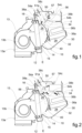
figure 1 is a schematic sectional view of a heating and/or air-conditioning device according to the invention, in the "full cold" or closed position; -
figure 2 is a view analogous toFigure 1 , in an intermediate mixing position; -
figure 3 is a view analogous to the preceding ones, in the "full hot" or open position; -
figure 4 is a partially sectional view of a part of the heating and/or air-conditioning device; -
figure 5 is a perspective view of a part of the box of the heating and/or air-conditioning device, seen from the side opposite to what is shown inFigure 4 ; -
figures 6 and 7 are respectively a front view and a perspective view of a distribution member of the heating and/or air-conditioning device; and -
figure 8 is a perspective view of a component of the distribution member shown inFigures 6 and 7 . - The device shown in the figures comprises a
box 10 delimiting anair inlet duct 12 configured to be supplied with an air flow (arrow F1) driven by acentrifugal fan 13. Thecentrifugal fan 13 conventionally includes ascrew 13a and animpeller 13b housed within thescrew 13a and operated by an electric motor (not shown). Thefan 13 is in turn supplied with an external air flow drawn from outside the vehicle cabin or a recirculation air flow drawn from inside the cabin. - The
air inlet duct 12 can house transversally an evaporator E connected to a conventional air-conditioning circuit in such a way as to produce at its outlet an air flow that can be air-conditioned if the evaporator is active. - Downstream, the
air inlet duct 12 opens into a section of the air-conditioning device dedicated to mixing hot and cold air streams. At the inlet of this mixing section, the air inlet duct therefore defines anair inlet 14 delimited byopposite walls housing 10. - The
air inlet 14 defines a convergence zone that supplies, on the one hand, anair transmission branch 26, and on the other hand, anair heating branch 28. Theair heating branch 28 is externally delimited by acurved wall 30 of thehousing 10 and internally by aninner partition 32. Conversely, theair transmission branch 26 is internally delimited by theinner partition 32 and externally by an extension ofwall 16. Thebranches air inlet 14 and at anotherdownstream convergence zone 34, which will hereinafter be referred to as the mixing zone. - In the
air heating branch 28, one ormore heating elements - The
mixing zone 34 conventionally communicates with various air outlets that serve to distribute the treated air to different areas inside the motor vehicle. For instance, there may be air outlets 37a configured to be connected to vents serving to defrost/defog the vehicle windshield,air outlets 38a configured to be connected to vents positioned at the lower part of the vehicle cabin (foot heating),air outlets 38c configured to be connected to dashboard ventilation vents, and so on. - Within the
housing 10, at the mixing section of the air-conditioning device, amixing member 40 is mounted. - In the example illustrated in
Figures 1 to 3 , themixing member 40 is located between theair inlet 14 and the air transmission andheating branches Figures 4 and5 ), themixing member 40 can be positioned at themixing zone 34. - The construction and type of movement of the mixing
member 40 are not essential for the purposes of the invention. - The mixing
member 40 is capable of oscillating between two extreme positions: - a closed or "full cold" position (represented by a dashed line in
Figure 1 ), wherein themixing member 40 prevents communication between theair inlet 14 and theair heating branch 28 and forces the air flow to pass through theair transmission branch 26, as indicated by the arrows F2. - an open or "full hot" position (represented by a dashed line in
Figure 3 ), in which themixing member 40 prevents communication between theair inlet 14 and theair transmission branch 26 and forces the air flow to pass through theair heating branch 28, as indicated by the arrows F3. - An intermediate position of the
mixing member 40 is shown inFigure 2 . - An
air distribution member 50 is interposed between the mixing section and theair outlets 38a to 38c of the heating and/or air-conditioning device. Thisair distribution member 50 is shown in detail inFigures 4 and6 to 8 . In the embodiment ofFigures 4 and5 , theair distribution member 50 is located immediately downstream of themixing member 40. Note that inFigure 4 , only the terminal parts of theair transmission branch 26 andair heating branch 28 near themixing zone 34 are shown. For a description of the remaining part of the heating and/or air-conditioning device, refer to the earlier description ofFigures 1 to 3 . - The air distribution member comprises an
enclosure 51 fixed to thebox 10 of the air-conditioning device, at themixing zone 34. According to alternative embodiments not illustrated, theenclosure 51 could be formed, at least partially, in a single piece with a portion of thebox 10 wherein themixing zone 34 is located. - The
enclosure 51 is implemented as a shell comprising atop wall 52 and a plurality ofside walls top wall 52. On the side opposite thetop wall 52, theenclosure 51 is open and configured to be coupled to a wall 10' of thebox 10. - In cooperation with this wall 10', the
enclosure 51 defines within it a stratification funnel comprising acircular chamber 51a from which threeducts side walls enclosure 51. At the convergence of each pair of ducts, theside walls enclosure 51 have a respective apical portion extending in a circumferential arc and located at the perimeter of thecircular chamber 51a. Theenclosure 51 thus defines afirst distribution inlet 55a, asecond distribution inlet 55b, and adistribution outlet 55c, all facing thecircular chamber 51a and interspersed with the aforementioned apical portions of theside walls enclosure 51. Theduct 54a enters thecircular chamber 51a through thefirst distribution inlet 55a, while theduct 54b enters thecircular chamber 51a through thesecond distribution inlet 55b. Theduct 54c departs from thecircular chamber 51a through thedistribution outlet 55c. - The
first distribution inlet 55a and thesecond distribution inlet 55b are respectively connected to theair transmission branch 26 and theair heating branch 28 through theirrespective ducts distribution outlet 55c is connected with one of theair outlets 38a to 38c of the heating and/or air-conditioning device throughduct 54c. Specifically, thedistribution outlet 55c and its associatedduct 54c are connected to thefoot heating outlet 38b. As can be appreciated inFigure 4 , the shape of theenclosure 51 is designed to be coupled with the corresponding passages formed in thebox 10 of the air-conditioning device, and specifically with theair transmission branch 26, theair heating branch 28, and the passages leading to thevarious air outlets 38a to 38c. This coupling concerns only a portion of the extension of these ducts in the vertical direction (orthogonal to the plane of the drawings inFigures 1 to 4 ). Consequently, only part of the air flows from theair transmission branch 26 andair heating branch 28 is channelled into theenclosure 51. The remaining part follows a parallel path from the mixingzone 34 to theair outlets 38a to 38c, without being involved in the adjustment imparted by theair distribution member 50. In other words, theenclosure 51 divides the mixingzone 34 into a main chamber 34' (which, with respect to the direction orthogonal to the plane of the drawings inFigures 1 to 4 , is located above theenclosure 51 and represented by an area enclosed by a dashed-dotted line inFigure 4 ) and into thestratification funnel enclosure 51, whereby the air flow coming from theair transmission branch 26 and/or theair heating branch 28 can be divided into a main flow fraction passing through the main chamber 34' and a secondary flow fraction passing through thestratification funnel - As shown in
Figures 5 and7 , theenclosure 51 also includes a septum 51' that divides theair outlet 38b into amain outlet 38b' fluidically connected with the main chamber 34' and asecondary outlet 38b" fluidically connected with thestratification funnel enclosure 51 that houses the septum 51' cooperates with the walls of thebox 10 of the heating and/or air-conditioning device to define a secondary duct (i.e.,duct 54c) connecting thesecondary outlet 38b" with thestratification funnel main duct 10" connecting themain outlet 38b' with the main chamber 34' of the mixingzone 34. The septum 51' provides separation between themain duct 10" and thesecondary duct 54c. - Associated with the
air outlet 38b is anoutlet door 60, in particular a rotatable door, comprising a main door sector 60' and asecondary door sector 60" operable to close or open themain outlet 38b' and thesecondary outlet 38b" respectively. For the movement of theoutlet door 60, an actuator (not shown) is provided. In the illustrated example, theoutlet door 60 includes ashaft 61 rotatably mounted on thebox 10 of the heating and/or air-conditioning device, and whereon the main door sector 60' and thesecondary door sector 60" are positioned. The main door sector 60' and thesecondary door sector 60" rotate together with theshaft 61. - Within the circular chamber 5 1a is mounted a
drum flap 56 rotatably mounted about a z-axis orthogonal to the directions leading from thefirst distribution inlet 55a and thesecond distribution inlet 55b to thedistribution outlet 55c respectively. In the illustrated example, thedrum flap 56 includes at opposite endsrespective pivots top wall 52 of theenclosure 51 and the wall 10' of thebox 10. In particular, thepivot 56b coupled to the wall 10' of thebox 10 is configured to be connected to an actuator (not shown) for controlling thedrum flap 56. - The
drum flap 56 has a body with circular symmetry about the z-axis, through which apassage channel 57 is formed, extending in a diametrical direction. - The
drum flap 56 is movable between a first position wherein thepassage channel 57 of thedrum flap 56 puts thefirst distribution inlet 55a in communication with thedistribution outlet 55c (Figure 1 ), a second position wherein thepassage channel 57 of thedrum flap 56 puts thesecond distribution inlet 55b in communication with thedistribution outlet 55c (Figure 3 ), and at least one intermediate position wherein thepassage channel 57 of thedrum flap 56 puts both thedistribution inlets distribution outlet 55c (Figure 2 ). - In the first position (
Figure 1 ), thepassage channel 57 of thedrum flap 56 is aligned with thefirst distribution inlet 55a and thedistribution outlet 55c, while the portion of thedrum flap 56 laterally delimiting thepassage channel 57 blocks thesecond distribution inlet 55b. In the second position (Figure 3 ), thepassage channel 57 of thedrum flap 56 is aligned with thesecond distribution inlet 55b and thedistribution outlet 55c, while the portion of thedrum flap 56 laterally delimiting thepassage channel 57 blocks thefirst distribution inlet 55a. In the third position (Figure 2 ), thepassage channel 57 of thedrum flap 56 is arranged to allow air flows from both theair transmission branch 26 and theair heating branch 28 to be simultaneously channelled to theair outlet 38b. - For simplicity, in
Figure 1 , theair distribution member 50 is shown in the first position, with the mixingmember 40 in the closed position; inFigure 2 , theair distribution member 50 is shown in an intermediate position, with the mixingmember 40 in an intermediate position; and inFigure 3 , theair distribution member 50 is shown in the second position, with the mixingmember 40 in the open position. However, it should be understood that there is no such fixed relationship between the position of theair distribution member 50 and the position of the mixingmember 40; theair distribution member 50 can therefore be adjusted to its different positions for each of the positions of the mixingmember 40. While, in general, the position of the mixingmember 40 is determined by a control unit of the air-conditioning device based on a temperature setting entered by the user, the position of theair distribution member 50 is automatically set by the control unit based on operational protocols defined by the manufacturer. - Thanks to the above-described arrangement, it is possible to actively adjust the channelling of the air flow from the mixing zone to the various air outlets of the heating and/or air-conditioning device, improving air stratification.
- It should be noted that the
flap 56 could be a rotatable flap of a type different from a drum door, such as, for instance, a swing flap or a butterfly flap. In this case, thechamber 51a should be adapted to the type of shape and movement of the flap. In any case, it is essential that the flap is movable between a first position wherein the flap puts only thefirst distribution inlet 55a in communication with thedistribution outlet 55c, a second position wherein the flap puts only thesecond distribution inlet 55b in communication with thedistribution outlet 55c, and at least one intermediate position wherein the flap puts bothdistribution inlets distribution outlet 55c. - In the examples described above, the
air distribution member 50 includes twoinlet ducts outlet duct 54c. It is possible to envision an air distribution member with two or more outlet ducts connected with two or more air outlets of the heating and/or air-conditioning device, one or more of which is provided with the dual outlet door described above.
Claims (5)
- Heating and/or air-conditioning device for a motor vehicle, comprising a mixing section comprising an air transmission branch (26) and an air heating branch (28), both supplied by an air inlet (14) and communicating with each other through a mixing zone (34), and mixing means (40) configured to distribute an air flow between the air transmission branch (26) and the air heating branch (28), wherein said mixing means (40) are movable between two extreme positions, comprising a closed position wherein they prevent communication between the air inlet (14) and the mixing zone (34) through the air heating branch (28) and force the air flow to pass through the air transmission branch (26), and an open position wherein they prevent communication between the air inlet (14) and the mixing zone (34) through the air transmission branch (26) and force the air flow to pass through the air heating branch (28);air distribution means (50) interposed between the mixing section and a plurality of air outlets (38a, 38b, 38c) of the heating and/or air-conditioning device, said air distribution means (50) being operable to control the distribution of the air flow between said air transmission branch (26) and air heating branch (28) and at least one outlet (38b) of said air outlets (38a, 38b, 38c);wherein said air distribution means (50) comprise an enclosure (51) arranged at the mixing zone (34), said enclosure (51) dividing the mixing zone (34) into a main chamber (34') and a stratification funnel (54a, 54b, 51a, 54c) enclosed by said enclosure (51), whereby the air flow is dividable into a main flow fraction passing through the main chamber (34') and a secondary flow fraction passing through the stratification funnel (54a, 54b, 51a, 54c);wherein said enclosure (51) divides said at least one outlet (38b) into a main outlet (38') fluidically connected with the main chamber (34') and into a secondary outlet (38") fluidically connected with the stratification funnel (54a, 54b, 51a, 54c); andwherein said at least one outlet (38b) is associated with an outlet door (60), comprising a main door sector (60') and a secondary door sector (60"), operable to close or open said main outlet (38') and said secondary outlet (38"), respectively;characterized in that said stratification funnel comprises a chamber (51a) and further comprises a first distribution inlet (55a) and a second distribution inlet (55b) facing the chamber (51a) and respectively connected with the air transmission branch (26) and the air heating branch (28), and at least one distribution outlet (55c) facing the chamber (51a) and connected with at least one of the air outlets (38a, 38b, 38c) of the heating and/or air-conditioning device;wherein said air distribution means (50) further comprise a flap (56) rotatably mounted in the chamber (51a) to control the distribution of the air flow between the distribution inlets (55a, 55b) and the at least one distribution outlet (55c).
- Device according to claim 1, wherein the flap (56) is movable between a first position wherein the flap (56) puts only the first distribution inlet (55a) in communication with the at least one distribution outlet (55c), a second position wherein the flap (56) puts only the second distribution inlet (55b) in communication with the at least one distribution outlet (55c), and at least one intermediate position wherein the flap (56) puts both distribution inlets (55a, 55b) in communication with the at least one distribution outlet (55c).
- Device according to claim 1 or 2, wherein said stratification funnel comprises a plurality of ducts (54a, 54b, 54c) extending radially from the chamber (51a), each duct being respectively connected to one of said distribution inlets and at least one distribution outlet (55a, 55b, 55c).
- Device according to any of the preceding claims, wherein the enclosure (51) is formed as a shell comprising a top wall (52) and a plurality of side walls (53b, 53c, 53d) projecting from a peripheral edge of the top wall (52), wherein on the side opposite the top wall (52) the enclosure (51) is coupled to a wall (10') of a box (10) of the heating and/or air-conditioning device.
- The device according to claim 4, wherein the flap (56) is rotationally coupled, at opposite ends, to the top wall (52) of the enclosure (51) and to the wall (10') of the box (10), respectively.
Applications Claiming Priority (1)
| Application Number | Priority Date | Filing Date | Title |
|---|---|---|---|
| IT102023000025896A IT202300025896A1 (en) | 2023-12-05 | 2023-12-05 | HEATING AND/OR AIR CONDITIONING DEVICE FOR A MOTOR VEHICLE |
Publications (1)
| Publication Number | Publication Date |
|---|---|
| EP4566854A1 true EP4566854A1 (en) | 2025-06-11 |
Family
ID=89983477
Family Applications (1)
| Application Number | Title | Priority Date | Filing Date |
|---|---|---|---|
| EP24217034.8A Pending EP4566854A1 (en) | 2023-12-05 | 2024-12-03 | Heating and/or air-conditioning device for a motor vehicle |
Country Status (2)
| Country | Link |
|---|---|
| EP (1) | EP4566854A1 (en) |
| IT (1) | IT202300025896A1 (en) |
Citations (3)
| Publication number | Priority date | Publication date | Assignee | Title |
|---|---|---|---|---|
| JP2005153824A (en) * | 2003-11-28 | 2005-06-16 | Zexel Valeo Climate Control Corp | Baffle plate for air conditioning and thermostat unit part for air conditioning unit using this |
| EP2055514A1 (en) * | 2006-08-22 | 2009-05-06 | Calsonic Kansei Corporation | Air conditioner for automobile |
| US20160082807A1 (en) * | 2014-09-18 | 2016-03-24 | Halla Visteon Climate Control Corp. | Mode door with integrated stratification features |
-
2023
- 2023-12-05 IT IT102023000025896A patent/IT202300025896A1/en unknown
-
2024
- 2024-12-03 EP EP24217034.8A patent/EP4566854A1/en active Pending
Patent Citations (3)
| Publication number | Priority date | Publication date | Assignee | Title |
|---|---|---|---|---|
| JP2005153824A (en) * | 2003-11-28 | 2005-06-16 | Zexel Valeo Climate Control Corp | Baffle plate for air conditioning and thermostat unit part for air conditioning unit using this |
| EP2055514A1 (en) * | 2006-08-22 | 2009-05-06 | Calsonic Kansei Corporation | Air conditioner for automobile |
| US20160082807A1 (en) * | 2014-09-18 | 2016-03-24 | Halla Visteon Climate Control Corp. | Mode door with integrated stratification features |
Also Published As
| Publication number | Publication date |
|---|---|
| IT202300025896A1 (en) | 2025-06-05 |
Similar Documents
| Publication | Publication Date | Title |
|---|---|---|
| US4406214A (en) | Bypass passageway construction for a vehicle air conditioner system | |
| US5101883A (en) | Method of assembly of single and multi-zone vehicle heating and a/c systems | |
| JP2004106635A (en) | Vehicle air conditioner | |
| CN104276004A (en) | Vehicle air conditioner | |
| CN103847462B (en) | The rear portion air-conditioning of vehicle | |
| US5890651A (en) | Air conditioning apparatus for vehicle | |
| KR101758722B1 (en) | Air conditioner for vehicle | |
| EP4566854A1 (en) | Heating and/or air-conditioning device for a motor vehicle | |
| JPWO2014058009A1 (en) | Air conditioner for vehicles | |
| EP4470808B1 (en) | Heating and/or air conditioning device for a motor vehicle | |
| EP3578397A1 (en) | Air conditionning system for vehicle | |
| JP2019137371A (en) | Blower unit for air conditioner for vehicle | |
| KR20180041573A (en) | Multi-planar air diverter. | |
| JP2004058940A (en) | Vehicle air conditioner | |
| JP7407429B2 (en) | Vehicle air conditioner | |
| KR101199791B1 (en) | Air conditioner for vehicles | |
| KR20230132011A (en) | Air-conditioner for vehicle | |
| JP2002370520A (en) | Air-conditioner for vehicle | |
| EP3636470B1 (en) | Air-conditioning device for a vehicle comprising an articulated flap | |
| JP5243674B2 (en) | Vehicle air distribution device | |
| KR101264625B1 (en) | Air conditioner for vehicle | |
| KR101200266B1 (en) | Air conditioner for vehicles | |
| KR101714469B1 (en) | Air conditioner for vehicle | |
| JP2009018780A (en) | Air conditioner for vehicles | |
| KR101669823B1 (en) | Air conditioner for vehicle |
Legal Events
| Date | Code | Title | Description |
|---|---|---|---|
| PUAI | Public reference made under article 153(3) epc to a published international application that has entered the european phase |
Free format text: ORIGINAL CODE: 0009012 |
|
| STAA | Information on the status of an ep patent application or granted ep patent |
Free format text: STATUS: THE APPLICATION HAS BEEN PUBLISHED |
|
| AK | Designated contracting states |
Kind code of ref document: A1 Designated state(s): AL AT BE BG CH CY CZ DE DK EE ES FI FR GB GR HR HU IE IS IT LI LT LU LV MC ME MK MT NL NO PL PT RO RS SE SI SK SM TR |
|
| STAA | Information on the status of an ep patent application or granted ep patent |
Free format text: STATUS: REQUEST FOR EXAMINATION WAS MADE |
|
| 17P | Request for examination filed |
Effective date: 20251125 |