EP4566771A1 - Hand and robot system - Google Patents
Hand and robot system Download PDFInfo
- Publication number
- EP4566771A1 EP4566771A1 EP23850125.8A EP23850125A EP4566771A1 EP 4566771 A1 EP4566771 A1 EP 4566771A1 EP 23850125 A EP23850125 A EP 23850125A EP 4566771 A1 EP4566771 A1 EP 4566771A1
- Authority
- EP
- European Patent Office
- Prior art keywords
- gripper
- holder
- reference axis
- lock
- coupler
- Prior art date
- Legal status (The legal status is an assumption and is not a legal conclusion. Google has not performed a legal analysis and makes no representation as to the accuracy of the status listed.)
- Pending
Links
Images








Classifications
-
- B—PERFORMING OPERATIONS; TRANSPORTING
- B25—HAND TOOLS; PORTABLE POWER-DRIVEN TOOLS; MANIPULATORS
- B25J—MANIPULATORS; CHAMBERS PROVIDED WITH MANIPULATION DEVICES
- B25J17/00—Joints
- B25J17/02—Wrist joints
- B25J17/0208—Compliance devices
-
- B—PERFORMING OPERATIONS; TRANSPORTING
- B25—HAND TOOLS; PORTABLE POWER-DRIVEN TOOLS; MANIPULATORS
- B25J—MANIPULATORS; CHAMBERS PROVIDED WITH MANIPULATION DEVICES
- B25J15/00—Gripping heads and other end effectors
- B25J15/0028—Gripping heads and other end effectors with movable, e.g. pivoting gripping jaw surfaces
-
- B—PERFORMING OPERATIONS; TRANSPORTING
- B25—HAND TOOLS; PORTABLE POWER-DRIVEN TOOLS; MANIPULATORS
- B25J—MANIPULATORS; CHAMBERS PROVIDED WITH MANIPULATION DEVICES
- B25J15/00—Gripping heads and other end effectors
- B25J15/02—Gripping heads and other end effectors servo-actuated
- B25J15/0253—Gripping heads and other end effectors servo-actuated comprising parallel grippers
- B25J15/0266—Gripping heads and other end effectors servo-actuated comprising parallel grippers actuated by articulated links
- B25J15/0273—Gripping heads and other end effectors servo-actuated comprising parallel grippers actuated by articulated links comprising linear guide means
-
- B—PERFORMING OPERATIONS; TRANSPORTING
- B25—HAND TOOLS; PORTABLE POWER-DRIVEN TOOLS; MANIPULATORS
- B25J—MANIPULATORS; CHAMBERS PROVIDED WITH MANIPULATION DEVICES
- B25J9/00—Program-controlled manipulators
- B25J9/16—Program controls
- B25J9/1679—Program controls characterised by the tasks executed
- B25J9/1687—Assembly, peg and hole, palletising, straight line, weaving pattern movement
Definitions
- the technique disclosed here relates to hands and robot systems.
- Patent Document 1 discloses a hand that grips a component and inserts the gripped component into a hole in another component.
- Patent Document 1 Japanese Patent Application Publication No. H05-285747
- a positional accuracy of the hand has a significant influence on the work.
- the work of inserting a component into a hole if the positions of the component and the hole are misaligned, the work of inserting the component is difficult.
- the work of inserting the component is also difficult. This is not limited to the insertion work of components, the same holds for other work such as the work of picking up a component and the work of placing a component at a predetermined place.
- enhancement of positional accuracy of the hand can be effective.
- loads of sensing and control in controlling the position of the hand increase.
- a hand disclosed here includes: a hand body; a gripper that grips a workpiece; a coupler that couples the gripper to the hand body such that a relative position of the gripper to the hand body is changeable; and a lock that locks movement of the coupler, wherein the lock switches, by an opening/closing action, between a locked state where the lock locks movement of the coupler by contacting the gripper and an unlocked state where the lock unlocks movement of the coupler by separating from the gripper.
- a robot system disclosed here includes: the hand; a robot arm to which the hand is coupled; and a controller that controls the robot arm and the hand, wherein the controller causes the robot arm and the hand to perform insertion work of inserting the workpiece gripped by the hand into a predetermined hole.
- the robot system eases work by a hand.
- FIG. 1 is a schematic view illustrating a configuration of a robot system 1000.
- the robot system 1000 includes a robot 110 including a robot arm 120 and a hand 100, and a controller 130 that controls the robot arm 120 and the hand 100.
- the hand 100 is coupled to the robot arm 120 (specifically a distal end of the robot arm 120).
- the hand 100 grips a workpiece to perform various treatments.
- the controller 130 causes the robot arm 120 and the hand 100 to perform insertion work of inserting a workpiece gripped by the hand 100 into a predetermined hole.
- the insertion of the workpiece herein includes press fitting of the workpiece into the hole and screwing of the workpiece into a screw hole.
- the robot 110 is, for example, an industrial robot.
- the robot 110 causes the hand 100 to act, that is, to move by the robot arm 120.
- the hand 100 is a so-called end effector.
- the hand 100 grips a workpiece.
- the hand 100 also regrips the workpiece, combines the workpiece to another workpiece, and so forth.
- the robot arm 120 includes links 121, joints 122, and motors.
- Each of the joints 122 rotatably connects adjacent two of the links 121.
- Each of the motors rotationally drives the joints 122.
- Each motor is, for example, a servo motor.
- FIG. 2 is a perspective view of the hand 100.
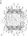
- FIG. 3 is a plan view of the hand 100.
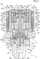
- FIG. 4 is a cross-sectional view of the hand 100 taken along line IV-IV in FIG. 3 .
- FIG. 5 is a cross-sectional view of the hand 100 taken along line V-V in FIG. 3 .
- some elements are not shown for easy understanding of the configuration. The same holds for the following drawings.
- the hand 100 includes a hand body 2, a gripper 3 that grips a workpiece, and a coupler 4 that couples the gripper 3 to the hand body 2.
- a predetermined first reference axis X is defined in the hand body 2 .
- a predetermined second reference axis ⁇ is defined in the gripper 3.
- the coupler 4 couples the gripper 3 to the hand body 2 such that the relative position of the gripper 3 to the hand body 2 is changeable.
- the coupler 4 includes a decentering coupler 41 that supports the gripper 3 such that the second reference axis ⁇ is capable of being decentered with respect to the first reference axis X, and a tilt coupler 47 that supports the gripper 3 such that the second reference axis ⁇ is capable of being tilted with respect to the first reference axis X.
- the hand 100 can move the workpiece gripped by the gripper 3 straight in the direction of the first reference axis X while rotating the workpiece about the first reference axis X. Accordingly, the hand 100 inserts the workpiece into a hole or screw the workpiece into a screw hole, for example.
- a side to which the gripper 3 advances from the hand body 2 along the first reference axis X will be hereinafter referred to as an "advancing side” or a “distal side” and a side to which the gripper 3 retracts toward the hand body 2 along the first reference axis X will be hereinafter referred to as a "retracting side” or a "body side.”
- the hand 100 further includes a lock 9 that locks movement of the coupler 4.
- the lock 9 switches between a locked state where the lock 9 locks movement of the coupler 4 by contacting the gripper 3 and an unlocked state where the lock 9 unlocks movement of the coupler 4 by separating from the gripper 3.
- the lock 9 switches between the locked state and the unlocked state by an opening/closing action.
- movement action of coupler 4 is locked so that the relative position of the gripper 3 to the hand body 2 becomes unchangeable.
- the lock 9 switches to the unlocked state, the coupler 4 becomes freely movable so that the relative position of the gripper 3 to the hand body 2 becomes changeable.
- the hand 100 further includes first buffers 10 that absorb a force exerted on the gripper 3 in the direction of the first reference axis X.
- the hand body 2 is a box-shaped casing.
- the hand body 2 is an approximately rectangular parallelepiped.
- the hand body 2 includes a straight-moving actuator 6 that causes the gripper 3 to move straight in direction of the first reference axis X with respect to the hand body 2, a rotation actuator 7 that rotates the gripper 3 about the second reference axis ⁇ , and an opening/closing actuator 8 that opens and closes the gripper 3.
- the hand body 2 houses the straight-moving actuator 6, the rotation actuator 7, the opening/closing actuator 8, and the first buffers 10.
- the gripper 3 includes a base 31, fingers 32 supported by the base 31, and an operator 33 that causes the fingers 32 to perform an opening/closing action.
- the gripper 3 includes three fingers 32.
- the base 31 is approximately tubular. Specifically, the base 31 has a first cylinder 34a, a second cylinder 34b, a ceiling 34c, and a bottom 34d.
- the ceiling 34c is illustrated in FIG. 4 and other drawings. As illustrated in FIG. 4 , for example, the first cylinder 34a and the second cylinder 34b have substantially tubular coaxial shapes extending along the second reference axis ⁇ serving as a center axis.
- the ceiling 34c is located at one end of the first cylinder 34a in the direction of the second reference axis ⁇ .
- the ceiling 34c has a substantially disc shape about the second reference axis ⁇ .
- the ceiling 34c has an opening substantially at the center thereof.
- the first cylinder 34a and the ceiling 34c are formed as a single unit.
- the second cylinder 34b is attached to the ceiling 34c.
- the bottom 34d is attached to the other end of the first cylinder 34a in the direction of the second reference axis ⁇ .
- the bottom 34d has a substantially disc shape about the second reference axis ⁇ .
- the bottom 34d is formed as a separate component from the first cylinder 34a and the ceiling 34c and attached to the first cylinder 34a.
- the bottom 34d has three slits 34e penetrating the bottom 34d in the thickness direction and extending radially about the second reference axis ⁇ .
- FIG. 4 shows one slit 34e.
- the slits 34e are arranged at regular intervals (i.e., at an interval of 120 degrees) in the circumferential direction about the second reference axis ⁇ .
- each of the fingers 32 is supported by the bottom 34d to be slidable along the slits 34e. Specifically, each of the fingers 32 has a first end 32a supported by the base 31 and a second end 32b to contact a workpiece. The first end 32a is located at an inner side of the base 31 and slidably engaged with the bottom 34d. Accordingly, the fingers 32 are supported by the base 31 to be movable radially about the second reference axis ⁇ . The fingers 32 extend from the base 31 substantially in parallel with the second reference axis ⁇ .
- the three fingers 32 are arranged at regular intervals (i.e., at an interval of 120 degrees) in the circumferential direction about the second reference axis ⁇ .
- the three fingers 32 move toward or away from each other radially about the second reference axis ⁇ to thereby open and close.
- the fingers 32 grip a workpiece at the second ends 32b.
- the operator 33 includes links 36 coupled to the fingers 32, a feed screw 37 that extends along the second reference axis ⁇ serving as a center axis of the feed screw 37 and rotates about the second reference axis ⁇ , and a block 38 to which the feed screw 37 is screwed and the links 36 are coupled.
- the operator 33 is a so-called linkage.
- One link 36 is coupled to one finger 32.
- One end of the link 36 is rotatably coupled to the finger 32 (specifically, the first end 32a).
- the feed screw 37 and the block 38 define a so-called screw feeder.
- the feed screw 37 is located in the base 31.
- the feed screw 37 extends along the second reference axis ⁇ serving as a center axis of the feed screw 37, and is supported by the bottom 34d to be rotatable about the second reference axis ⁇ .
- the links 36 are coupled to the block 38. Specifically, an end of each link 36 opposite to an end coupled to the finger 32 is rotatably coupled to the block 38. That is, one end of each link 36 is coupled to the finger 32, and the other end of the link 36 is coupled to the block 38.
- the fingers 32 penetrate the slits 34e and do not rotate about the second reference axis ⁇ with respect to the base 31. Accordingly, the block 38 coupled to the three fingers 32 through the links 36 does not rotate about the second reference axis ⁇ with respect to the base 31, either.
- the block 38 moves in the direction of the second reference axis ⁇ .
- the links 36 move cooperatively, and accordingly, the fingers 32 move radially about the second reference axis ⁇ .
- the fingers 32 move radially outward.
- the block 38 moves away from the bottom 34d, the fingers 32 move radially inward.
- the coupler 4 couples the base 31 to the hand body 2. As illustrated in FIG. 4 , the coupler 4 is coupled to the rotation actuator 7 of the hand body 2. The coupler 4 is located inside the second cylinder 34b.
- FIG. 6 is a perspective cross-sectional view of the decentering coupler 41.
- the decentering coupler 41 is coupled to the rotation actuator 7.
- the rotation actuator 7 includes a rotation shaft 71 extending along the first reference axis X serving as a center axis of the rotation actuator 7, which will be described later in detail.
- a flange-shaped first disc 71c and a second disc 71d each expanding in a plane substantially orthogonal to the first reference axis X are located at a first end 71a that is one of two ends of the rotation shaft 71 closer to the coupler 4 than the other end.
- the first disc 71c is located closer to the distal side of the first end 71a than the second disc 71d is.
- the decentering coupler 41 is coupled to the first end 71a of the rotation shaft 71.
- the decentering coupler 41 includes a decentered body 42 coupled to the rotation shaft 71 such that the decentered body 42 is movable in a direction substantially orthogonal to the first reference axis X.
- the decentered body 42 includes a substantially tubular cylinder 42a, a substantially disc-shaped ceiling 42b, and a substantially disc-shaped bottom 42c.
- the decentered body 42 has a substantially tubular box shape as a whole.
- the cylinder 42a, the ceiling 42b, and the bottom 42c are coaxially arranged.
- the cylinder 42a extends along an axis C serving as a center axis of the cylinder 42a, and the axis of each of the ceiling 42b and the bottom 42c is also the axis C.
- the ceiling 42b has an opening substantially at the center thereof.
- the bottom 42c has an opening substantially at the center thereof.
- the decentered body 42 houses the first disc 71c of the rotation shaft 71. That is, the rotation shaft 71 penetrates the opening of the ceiling 42b, and the first disc 71c is located between the ceiling 42b and the bottom 42c.
- the first disc 71c is substantially parallel to each of the ceiling 42b and the bottom 42c. That is, the axis C is substantially parallel to the first reference axis X.
- Rolling elements 43 are arranged circumferentially about the first reference axis X between the ceiling 42b and the first disc 71c. Similarly, rolling elements 43 are arranged circumferentially about the first reference axis X between the bottom 42c and the first disc 71c. In this example, the rolling elements 43 are balls. Rolling of the rolling elements 43 allows the decentered body 42 to move in a direction substantially orthogonal to the first reference axis X with respect to the rotation shaft 71. At this time, the decentered body 42 moves in parallel with a direction substantially orthogonal to the first reference axis X while keeping the posture (i.e., maintaining the substantially parallel relationship between the axis C and the first reference axis X). The decentered body 42 can move in parallel within a range in which the cylinder 42a contacts the first disc 71c. It should be noted that the decentered body 42 cannot move in the direction of the first reference axis X with respect to the rotation shaft 71.
- the gripper 3 is coupled to the decentered body 42 through the tilt coupler 47. Accordingly, the gripper 3 can also move in the direction substantially orthogonal to the first reference axis X with respect to the rotation shaft 71 together with the decentered body 42.
- the decentering coupler 41 also includes a second coupling 45.
- the second coupling 45 coupes the rotation shaft 71 and the gripper 3.
- the second coupling 45 is a coupling that couples two decentered substantially parallel axes, and transfers rotation between the two decentered axes.
- the second coupling 45 transfers rotation of the rotation 71 to the gripper 3 with the second reference axis ⁇ decentered with respect to the first reference axis X.
- the second coupling 45 is a so-called Oldham coupling.
- the second coupling 45 includes a second disc 71d as a first hub, an insert 45a, and a decentered body 42 as a second hub.
- the decentered body 42, the insert 45a, and the second disc 71d are arranged in this order from the base 31 in the direction of the first reference axis X.
- the second disc 71d is integrated with the rotation shaft 71 (specifically, the first end 71a).
- the second disc 71d and the insert 45a are coupled to each other to be movable in a first direction B1 substantially orthogonal to the first reference axis X.
- the insert 45a and the decentered body 42 are coupled to each other to be movable in the second direction B2 substantially orthogonal to the first reference axis X and to the first direction B1. That is, the decentered body 42 is movable with respect to the second disc 71d within a plane substantially orthogonal to the first reference axis X. At this time, the decentered body 42 moves in parallel with a direction substantially orthogonal to the first reference axis X without changing the posture. It should be noted that the decentered body 42 cannot rotate about the first reference axis X with respect to the second disc 71d.
- the rotation shaft 71 penetrates the insert 45a and enters the inside of the decentered body 42.
- the second disc 71d rotates integrally with the rotation shaft 71.
- the decentered body 42 rotates together with the second disc 71d because the decentered body 42 is non-rotatable with respect to the second disc 71d.
- the decentered body 42 rotates while moving in parallel relative to the rotation shaft 71 in a direction substantially orthogonal to the first reference axis X so that the decentered body 42 thereby rotates about the axis C while keeping a positional relationship between the axis C and the first reference axis X. That is, rotation about the first reference axis X input to the second disc 71d is output to the decentered body 42 as rotation about the axis C decentered with respect to the first reference axis X. Since the gripper 3 is coupled to the decentered body 42, when the decentered body 42 rotates, the gripper 3 rotates together with the decentered body 42.
- FIG. 7 is a perspective cross-sectional view of the tilt coupler 47.
- the tilt coupler 47 includes a third coupling 48.
- the third coupling 48 couples the rotation shaft 71 and the gripper 3 to each other.
- the third coupling 48 is a coupling that couples two axes that tilt relative to each other (i.e., two axes with angular misalignment) and transfers rotation between two axes that tilt relative to each other.
- the third coupling 48 transfers rotation of the rotation shaft 71 to the gripper 3 with the second reference axis ⁇ tilted with respect to the first reference axis X.
- the tilt coupler 47 not only couples the gripper 3 to the rotation shaft 71 such that the gripper 3 is capable of being tilted with respect to the rotation shaft 71, but also transfers rotation of the rotation shaft 71 to the gripper 3 with the second reference axis ⁇ tilted with respect to the first reference axis X.
- the third coupling 48 couples the rotation shaft 71 and the gripper 3 to each other with interposition of the decentering coupler 41.
- the third coupling 48 includes a coupling element 48a.
- the coupling element 48a has a substantially ring shape.
- the coupling element 48a has a first rotation axis D1 and a second rotation axis D2 extending in directions approximately orthogonal to each other.
- the first rotation axis D1 and the second rotation axis D2 are present in the same plane, and the first rotation axis D1 and the second rotation axis D2 are approximately orthogonal to each other.
- the decentered body 42 is coupled to the coupling element 48a to be rotatable about the first rotation axis D1. More specifically, the bottom 42c of the decentered body 42 is coupled to the coupling element 48a.
- the first rotation axis D1 is substantially orthogonal to the axis C of the decentered body 42.
- the base 31 is coupled to the coupling element 48a to be rotatable about the second rotation axis D2. More specifically, the ceiling 34c of the base 31 is coupled to the coupling element 48a.
- the second rotation axis D2 is substantially orthogonal to the second reference axis ⁇ of the gripper 3.
- the coupling element 48a is freely rotatable about the first rotation axis D1 with respect to the decentered body 42, and the base 31 is freely rotatable about the second rotation axis D2 with respect to the coupling element 48a. Accordingly, the gripper 3 is capable of being tilted with respect to the axis C of the decentered body 42.
- the third coupling 48 is a so-called universal coupling, more specifically, a cross coupling.
- the decentering coupler 41 When a force of moving the hand body 2 and the gripper 3 in a direction substantially orthogonal to the first reference axis X is applied to at least one of the hand body 2 or the gripper 3, the decentered body 42 moves in a direction substantially orthogonal to the first reference axis X with respect to the rotation shaft 71 by rolling of the rolling elements 43. At the same time, the insert 45a moves in the first direction B1 relative to the second disc 71d, and the decentered body 42 as a second hub moves in the second direction B2 relative to the insert 45a.
- the decentered body 42 moves relative to the hand body 2 such that the axis C is decentered with respect to the first reference axis X.
- the gripper 3 coupled to the decentered body 42 moves relative to the hand body 2 such that the second reference axis ⁇ is decentered with respect to the first reference axis X.
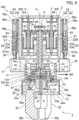
- FIG. 8 is a cross-sectional view of the hand 100 illustrating a state where the gripper 3 has moved in the second direction B2 relative to the hand body 2.
- the decentered body 42 has moved in the second direction B2 in parallel with the insert 45a.
- the gripper 3 coupled to the decentered body 42 has also moved in the second direction B2 in parallel with the insert 45a.
- the second reference axis ⁇ of the gripper 3 is decentered with respect to the first reference axis X of the hand body 2.
- the insert 45a can move in the first direction B1 in parallel with the second disc 71d. Accordingly, the gripper 3 coupled to the second disc 71d through the insert 45a can also move in the first direction B1 in parallel with the second disc 71d.
- Such parallel movement of the gripper 3 in the first direction B1 and the parallel movement of the gripper 3 in the second direction B2 occur in combination so that the gripper 3 thereby moves in parallel in any direction substantially orthogonal to the first reference axis X and is decentered with respect to the first reference axis X.
- the hand body 2 moves relative to the gripper 3 in a direction substantially orthogonal to the first reference axis X such that the second reference axis ⁇ is decentered with respect to the first reference axis X.
- the rotation shaft 71 rotates about the first reference axis X with the second reference axis ⁇ , that is, the axis C, restrained at a position decentered with respect to the first reference axis X
- the insert 45a moves relative to the second disc 71d and the decentered body 42 moves relative to the insert 45a. Accordingly, the decentered body 42 rotates about the axis C while keeping the decentered state between the axis C and the first reference axis X.
- the decentering coupler 41 not only decenters the gripper 3 with respect to the first reference axis X but also transfers rotation of the rotation shaft 71 about the first reference axis X to the decentered body 42 as rotation about the axis C decentered with respect to the first reference axis X. Since the gripper 3 is coupled to the decentered body 42, the gripper 3 also rotates about the second reference axis ⁇ decentered with respect to the first reference axis X.
- the decentered body 42 that is, the gripper 3 is coupled to the rotation shaft 71 by the first disc 71c and the rolling elements 43 and by the second coupling 45 such that the gripper 3 is movable in parallel in the direction substantially orthogonal to the first reference axis X.
- the first disc 71c and the rolling elements 43 also have the function of transferring loads of components such as the gripper 3 and the workpiece in the direction of the first reference axis X to the rotation shaft 71 such that the loads are not exerted only on the second coupling 45.
- the second coupling 45 also has the function of transferring rotation between the first reference axis X and the axis C decentered from each other.
- the base 31 is allowed to rotate about the first rotation axis D1 and the second rotation axis D2 with respect to the decentered body 42.
- the second reference axis ⁇ of the base 31 is allowed to tilt with respect to the axis C of the decentered body 42.
- the axis C of the decentered body 42 is substantially parallel to the first reference axis X.
- the second reference axis ⁇ of the base 31 is tilted with respect to the first reference axis X.
- FIG. 9 is a cross-sectional view of the hand 100 illustrating a state where the gripper 3 has rotated about the first rotation axis D1 with respect to the hand body 2.
- the base 31 and the coupling element 48a rotate about the first rotation axis D1 with respect to the decentered body 42. Consequently, the second reference axis ⁇ of the gripper 3 tilts with respect to first reference axis X of the hand body 2.
- the base 31 can rotate about the second rotation axis D2 with respect to the coupling element 48a. Consequently, second reference axis ⁇ of the gripper 3 tilts in a direction different from that in FIG. 9 with respect to the first reference axis X of the hand body 2.
- Such rotation of the gripper 3 about the first rotation axis D1 and rotation about the second rotation axis D2 occur in combination so that the gripper 3 thereby tilts in any direction with respect to the first reference axis X.
- the hand body 2 moves relative to the gripper 3 such that the second reference axis ⁇ is tilted with respect to the first reference axis X.
- the coupling element 48a rotates about the first rotation axis D1 relative to the decentered body 42 and the base 31 rotates about the second rotation axis D2 relative to the coupling element 48a so that the base 31 rotates about the second reference axis ⁇ without a change in posture of the second reference axis ⁇ .
- the coupler 4 supports the gripper 3 such that the gripper 3 is capable of being decentered with respect to the first reference axis X and supports the gripper 3 such that the gripper 3 is capable of being tilted with respect to the first reference axis X.
- the coupler 4 transfers rotation of the rotation shaft 71 about the first reference axis X to the gripper 3 as rotation about the second reference axis ⁇ with the second reference axis ⁇ of the gripper 3 decentered or tilted with respect to the first reference axis X.
- the straight-moving actuator 6 moves the rotation shaft 71 in the direction of the first reference axis X to thereby move the gripper 3 straight in the direction of the first reference axis X.
- the rotation actuator 7 rotates the rotation shaft 71 about the first reference axis X to thereby rotate the gripper 3 about the first reference axis X.
- some elements are shared by the straight-moving actuator 6 and the rotation actuator 7.
- the straight-moving actuator 6 shares some elements with the opening/closing actuator 8.
- the rotation actuator 7 shares some elements with the opening/closing actuator 8.
- the straight-moving actuator 6 includes a second motor 61 that generates a driving force, and a straight-moving transfer 67 that transfers the driving force of the second motor 61 to the gripper.
- the second motor 61 is an example of a straight-moving driving source.
- the straight-moving transfer 67 includes a first gear train 62 that transfers a driving force (i.e., rotation torque) of the second motor 61, screw feeders 63, a rotation shaft 71, and a gear box 72. As illustrated in FIG. 4 , most part of the straight-moving actuator 6 is located in the hand body 2.
- the rotation shaft 71 is has a substantially tubular shape extending along the first reference axis X serving as a center axis of the rotation shaft 71.
- the rotation shaft 71 is supported by a bearing 12 attached to the hand body 2 to be movable in the direction of the first reference axis X and rotatable about the first reference axis X.
- One end of the rotation shaft 71 in the direction of the first reference axis X will be referred to as the first end 71a, and the other end of the rotation shaft 71 in the direction of the first reference axis X will be referred to as a second end 71b.
- the first end 71a is an end on the advancing side in the direction of the first reference axis X.
- the second end 71b is an end on the retracting side in the direction of the first reference axis X.
- the rotation shaft 71 penetrates the bottom 21 of the hand body 2.
- the first end 71a is located outside the hand body 2.
- a flange-shaped first disc 71c and a second disc 71d each expanding in a plane substantially orthogonal to the first reference axis X are located at the first end 71a of the rotation shaft 71.
- the first disc 71c is located closer to the distal end of the first end 71a than the second disc 71d is.
- the second motor 61 is located in the hand body 2.
- the second motor 61 is, for example, a servo motor and includes an encoder.
- a driver of the second motor 61 includes a current sensor.
- the second motor 61 is supported by the hand body 2.
- the first gear train 62 is located in the hand body 2.
- the first gear train 62 includes gears rotatably supported by the hand body 2.
- the first gear train 62 includes a first gear 62a, a second gear 62b, a third gear 62c, a fourth gear 62d, a fifth gear 62e, a sixth gear 62f, and a seventh gear 62g.
- the first gear 62a, the second gear 62b, the third gear 62c, the fourth gear 62d, the fifth gear 62e, and the sixth gear 62f are arranged in this order and mesh with one another.
- the seventh gear 62g meshes with the fourth gear 62d.
- the first gear 62a is attached to an output shaft of the second motor 61.
- the first gear 62a is a driving gear.
- the second gear 62b, the third gear 62c, the fourth gear 62d, the fifth gear 62e, the sixth gear 62f, and the seventh gear 62g are driven gears that transfer a driving force of the second motor 61.
- the second gear 62b and the sixth gear 62f transfer the driving force of the second motor 61 to the feed screw 64 of the straight-moving actuator 6.
- the fourth gear 62d transfers the driving force of the second motor 61 to the ball spline 73c of the rotation actuator 7.
- the seventh gear 62g transfers the driving force of the second motor 61 to a feed screw 910 of a lock actuator 93 described later.
- the third gear 62c and the fifth gear 62e are so-called intermediate gears (i.e., idle gears).
- the straight-moving actuator 6 includes two pairs of screw feeders 63.
- Each of the screw feeders 63 includes the feed screw 64 and a nut 65 as a straight-moving element that meshes with the feed screw 64.
- each feed screw 64 extends substantially in parallel with the first reference axis X.
- One of the feed screws 64 is non-rotatably coupled to the second gear 62b of the first gear train 62.
- the other feed screw 64 is non-rotatably coupled to the sixth gear 62f of the first gear train 62. That is, the two feed screws 64 rotate about the axis F integrally with the second gear 62b and the sixth gear 62f, respectively.
- Each nut 65 meshes with the feed screw 64.
- the nut 65 is housed in the gear box 72.
- the rotation of the nut 65 is stopped by the gear box 72 such that the nut 65 does not rotate about the axis F.
- Each nut 65 includes a cylindrical body 65a and a flange 65b fixed to the flange body 65a.
- the nut 65 is elastically pressed against the gear box 72 by the first buffers10 in the direction of the axis F, that is, in the direction of the first reference axis X.
- the first buffers 10 are springs. More specifically, the first buffers 10 are coil springs. In FIG. 4 the first buffers 10 are simplified. Each first buffer 10 is located on the advancing side of the flange 65b in the direction of the first reference axis X. The first buffer 10 is compressed between the flange 65b and the gear box 72. The first buffer 10 presses the gear box 72 by an elastic force to the advancing side in the direction of the first reference axis X.
- the gear box 72 is pressed against the nut 65 to the advancing side in the direction of the first reference axis X. Accordingly, when the nut 65 moves in the direction of the axis F, the gear box 72 moves in the direction of the axis F, that is, in the direction of the first reference axis X, integrally with the nut 65.
- the gear box 72 is supported by linear guides 28 illustrated in FIG. 3 to be movable in the direction of the first reference axis X.
- FIG. 3 does not show the gear box 72.
- the hand body 2 includes two linear guides 28 extending in the direction of the first reference axis X. Since the gear box 72 is supported by the linear guides 28, the gear box 72 cannot rotate about the first reference axis X.
- the rotation shaft 71 is coupled to the gear box 72 to be rotatable about the first reference axis X and immovable in the direction of the first reference axis X. When the gear box 72 moves in the direction of the first reference axis X, the rotation shaft 71 also moves in the direction of the first reference axis X together with the gear box 72.
- the rotation actuator 7 includes a second motor 61 that generates a driving force, and the rotation shaft 71 extending along the first reference axis X serving as a center axis of the rotation shaft 71 and rotatable about the first reference axis X by a driving force of the second motor 61.
- the rotation actuator 7 further includes the first gear train 62 that transfers a driving force of the second motor 61, the gear box 72, and a second gear train 73 that further transfers the driving force of the second motor 61 from the first gear train 62 to the rotation shaft 71. That is, the second motor 61, the first gear train 62, the rotation shaft 71, and the gear box 72 of the rotation actuator 7 are shared with the straight-moving actuator 6.
- the second motor 61 is an example of a rotational driving source.
- the second gear train 73 includes a first gear 73a and a second gear 73b.
- the first gear 73a and the second gear 73b mesh with each other.
- the first gear 73a is coupled to the fourth gear 62d of the first gear train 62 through a ball spline 73c.
- An axis G of the ball spline 73c is substantially parallel to the first reference axis X.
- the ball spline 73c is non-rotatably coupled to the fourth gear 62d. That is, the ball spline 73c rotates about the axis G integrally with the fourth gear 62d.
- the first gear 73a is coupled to the ball spline 73c to be non-rotatable about the axis G and movable in the direction of the axis G.
- the first gear 73a is supported by the gear box 72 to be immovable in the direction of the axis G and rotatable about the axis G. That is, when the ball spline 73c rotates about the axis G, the first gear 73a rotates about the axis G relative to the gear box 72 integrally with the ball spline 73c.
- the first gear 73a In a case where the gear box 72 moves in the direction of the first reference axis X, that is, in the direction of the axis G, the first gear 73a also moves in the direction of the axis G integrally with the gear box 72. Even when the position of the first gear 73a in the direction of the axis G changes, the first gear 73a rotates about the axis G integrally with the ball spline 73c.
- the second gear 73b is coupled to the rotation shaft 71 to be non-rotatable about the first reference axis X and immovable in the direction of the first reference axis X.
- the second gear 73b rotates about the first reference axis X integrally with the rotation shaft 71, and moves in the direction of the first reference axis X integrally with the rotation shaft 71.
- the second gear 73b is coupled to a portion of the rotation shaft 71 located inside the gear box 72. In a case where the gear box 72 moves in the direction of the first reference axis X, the rotation shaft 71 and the second gear 73b also move in the direction of the first reference axis X together with the gear box 72. At this time, meshing between the first gear 73a and the second gear 73b is maintained.
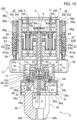
- FIG. 10 is a cross-sectional view of the hand 100 illustrating a state where the straight-moving actuator 6 has moved the gripper 3 in the direction of the first reference axis X.
- the first gear 73a rotates about the axis G integrally with the ball spline 73c.
- the rotation of the first gear 73a causes the second gear 73b to rotate about the first reference axis X, and the rotation shaft 71 rotates integrally with the second gear 73b.
- the rotation shaft 71 moves in the direction of the first reference axis X while rotating about the first reference axis X.
- the gripper 3 is coupled to the rotation shaft 71 through the coupler 4. Accordingly, the gripper 3 moves in the direction of the first reference axis X together with the rotation shaft 71. In addition, the gripper 3 moves while rotating about the second reference axis ⁇ .
- the opening/closing actuator 8 includes a first motor 81 that generates a driving force, and an opening/closing shaft 84 that extends along the first reference axis X serving as a center axis of the opening/closing shaft 84 and is caused to rotate about the first reference axis X by a driving force of the first motor 81.
- the opening/closing actuator 8 causes the operator 33 to act to thereby open or close the fingers 32.
- the opening/closing actuator 8 includes a first belt transfer 85, a second belt transfer 86, and the gear box 72. That is, the gear box 72 of the opening/closing actuator 8 is shared with the straight-moving actuator 6 and the rotation actuator 7.
- the first motor 81 is an example of an opening/closing driving source.
- the opening/closing shaft 84 has a substantially columnar shape extending along the first reference axis X serving as a center axis of the opening/closing shaft 84.
- One end of the opening/closing shaft 84 in the direction of the first reference axis X will be referred to as a first end 84a, and the other end in the direction of the first reference axis X will be referred to as a second end 84b.
- the first end 84a is an end on the advancing side in the direction of the first reference axis X.
- the second end 84b is an end on the retracting side in the direction of the first reference axis X.
- the opening/closing shaft 84 is inserted into the rotation shaft 71 to be rotatable about the first reference axis X.
- the second end 84b projects outward from the second end 71b of the rotation shaft 71.
- the opening/closing shaft 84 is supported by the gear box 72 to be rotatable about the first reference axis X and immovable in the direction of the first reference axis X. Accordingly, when the gear box 72 moves in the direction of the first reference axis X, the opening/closing shaft 84 also moves in the direction of the first reference axis X integrally with the gear box 72. At this time, since the rotation shaft 71 also moves in the direction of the first reference axis X integrally with the gear box 72, relative positions of the rotation shaft 71 and the opening/closing shaft 84 in the direction of the first reference axis X do not change.
- the opening/closing shaft 84 is inserted in the rotation shaft 71. Since the rotation shaft 71 is supported by the hand body 2 through the bearing 12, the opening/closing shaft 84 is substantially supported by the hand body 2.
- the first motor 81 is located in the hand body 2.
- the first motor 81 is located at a position different from the first gear train 62 in the direction of the first reference axis X.
- the first motor 81 is, for example, a servo motor and includes an encoder.
- a driver of the first motor 81 includes a current sensor.
- the first motor 81 is supported by the hand body 2.
- the first belt transfer 85 includes a first pulley 85a, a second pulley 85b, and a timing belt 85c.
- the first pulley 85a is attached to an output shaft of the first motor 81.
- the second pulley 85b is coupled to the ball spline 87.
- the ball spline 87 includes an axis E substantially parallel to the first reference axis X.
- the ball spline 87 is supported by the hand body 2 to be rotatable about the axis E.
- the second pulley 85b is coupled to the ball spline 87 to be non-rotatable about the axis E and immovable in the direction of the axis E.
- the timing belt 85c is wound around the first pulley 85a and the second pulley 85b.
- a driving force of the first motor 81 is transferred to the second pulley 85b through the first pulley 85a and the timing belt 85c.
- the ball spline 87 rotates integrally with the second pulley 85b about the axis E.
- the fourth pulley 86b is coupled to the second end 84b of the opening/closing shaft 84 projecting from the rotation shaft 71.
- the fourth pulley 86b is supported by the gear box 72 to be rotatable about the first reference axis X and immovable in the direction of the first reference axis X.
- the timing belt 86c is wound around the third pulley 86a and the fourth pulley 86b. Rotation of the ball spline 87 about the axis E is transferred to the fourth pulley 86b through the third pulley 86a and the timing belt 86c.
- a driving force of the first motor 81 is transferred to the opening/closing shaft 84 through the first belt transfer 85 and the second belt transfer 86. Accordingly, the opening/closing shaft 84 rotates about the first reference axis X. Since the opening/closing shaft 84 is inserted in the rotation shaft 71 to be rotatable about the first reference axis X, the opening/closing shaft 84 rotates about the first reference axis X independently of the rotation shaft 71. The opening/closing shaft 84 and the second belt transfer 86 are supported by the gear box 72 to be immovable in the direction of the first reference axis X.
- the coupler 4 includes a power transfer 5 that transfers a driving force of the opening/closing actuator 8 to the gripper 3.
- the power transfer 5 transfers a driving force of the opening/closing actuator 8 to the gripper 3 with the second reference axis ⁇ decentered or tilted with respect to the first reference axis X.
- the power transfer 5 includes a first coupling 51 that couples the opening/closing shaft 84 and the operator 33 to each other. Specifically, the first coupling 51 couples the opening/closing shaft 84 to the operator 33 of the gripper 3.
- the first coupling 51 transfers rotation of the opening/closing shaft 84 to the operator 33, that is, the gripper 3, with the second reference axis ⁇ decentered or tilted with respect to the first reference axis X.
- the first coupling 51 is a coupling that transfers rotation even when two axes have displacement such as angular misalignment or decentering.
- the first coupling 51 includes a first ball coupling 52 and a second ball coupling 53.
- the first ball coupling 52 and the second ball coupling 53 are simplified in the drawings.
- Each of the first ball coupling 52 and the second ball coupling 53 is a coupling having both functions as a universal joint (i.e., universal coupling) and a spline, and transfers rotation even when a shift such as angular misalignment or decentering occurs between two axes.
- the first ball coupling 52 couples the first end 84a of the opening/closing shaft 84 and the second ball coupling 53.
- the first ball coupling 52 transfers rotation of the opening/closing shaft 84 about the first reference axis X to the second ball coupling 53.
- the second ball coupling 53 couples the first ball coupling 52 and the feed screw 37 of the operator 33.
- the second ball coupling 53 transfers rotation of the first ball coupling 52 to the feed screw 37 as rotation about the second reference axis ⁇ .
- the first ball coupling 52 and the second ball coupling 53 absorb decentering and angular misalignment between the first reference axis X and the second reference axis ⁇ and transfers rotation about the first reference axis X as rotation about the second reference axis ⁇ .
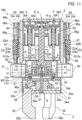
- FIG. 11 is a cross-sectional view of the hand 100 illustrating a state where the opening/closing actuator 8 causes the fingers 32 to perform an opening action.
- the gripper 3 is retracted in the direction of the first reference axis X.
- a rotation driving force of the first motor 81 is transferred to the ball spline 87 through the first pulley 85a, the timing belt 85c, and the second pulley 85b, as illustrated in FIGS. 3 and 5 .
- the ball spline 87 rotates about the axis E
- the third pulley 86a coupled to the ball spline 87 rotates about the axis E.
- Rotation of the third pulley 86a is transferred to the opening/closing shaft 84 through the timing belt 86c and the fourth pulley 86b. In this manner, the opening/closing shaft 84 rotates about the first reference axis X.
- Rotation of the opening/closing shaft 84 about the first reference axis X is transferred to the feed screw 37 of operator 33 as rotation about the second reference axis ⁇ through the power transfer 5.
- the feed screw 37 rotates about the second reference axis ⁇
- the block 38 moves in the direction of the second reference axis ⁇ .
- the fingers 32 move radially outward about the second reference axis ⁇ .
- the opening/closing actuator 8 opens and closes the fingers 32.
- the fingers 32 grip a workpiece and release gripping of the workpiece.
- the fingers 32 open or close such that the distances from the second reference axis ⁇ are the same. That is, the fingers 32 open and close about the second reference axis ⁇ .
- the direction of movement of the block 38 in the direction of the second reference axis ⁇ is switched depending on the rotation direction of the first motor 81.
- the position of the fingers 32 in the radial direction about the second reference axis ⁇ is detected based on an encoder output of the first motor 81.
- a rotation torque of the first motor 81 in opening or closing of the three fingers 32 is detected based on a detection result of the current sensor.
- the opening/closing shaft 84 and the second belt transfer 86 supported by the gear box 72 also move in the direction of the first reference axis X together with the rotation shaft 71.
- a driving force of the first motor 81 is kept in a state where the driving force can be transferred to the opening/closing shaft 84 through the first belt transfer 85 and the second belt transfer 86. That is, even when the rotation shaft 71 and the gripper 3 move in the direction of the first reference axis X, the fingers 32 of the gripper 3 can be opened or closed by the driving force of the first motor 81.
- the gripper 3 is rotated about the first reference axis X by the rotation actuator 7. That is, the base 31 and the fingers 32 rotate about the first reference axis X.
- the opening/closing shaft 84 rotates about the first reference axis X
- the feed screw 37 does not rotate about the first reference axis X, either.
- the base 31 rotates about the first reference axis X with respect to the feed screw 37. Consequently, the block 38 moves in the direction of the second reference axis ⁇ and the opening/closing state of the fingers 32 changes.
- the first motor 81 rotates the opening/closing shaft 84 about the first reference axis X in conformity with rotation of the gripper 3 about the first reference axis X.
- the first motor 81 is subjected to torque control so that a torque of the first motor 81 is controlled to be kept uniform.
- the fingers 32 move in the direction of the first reference axis X, while rotating about the first reference axis X with the opening/closing state maintained (e.g., a state where the fingers 32 grip a workpiece maintained).
- the second reference axis ⁇ of the gripper 3 is capable of being decentered with respect to the first reference axis X, as illustrated in FIG. 8 .
- the second reference axis ⁇ of the gripper 3 is capable of being tilted with respect to the first reference axis X, as illustrated in FIG. 9 . Even in such cases, the first ball coupling 52 and the second ball coupling 53 are deformed so that the state where the opening/closing shaft 84 and the operator 33 are coupled is thereby maintained.
- first coupling 51 includes two couplings, that is, the first ball coupling 52 and the second ball coupling 53, the first coupling 51 can be flexibly used for decentering and tilting between the first reference axis X and the second reference axis ⁇ .
- the first buffers 10 elastically support the gripper 3 in the direction of the first reference axis X.
- the first buffers 10 absorb a force exerted on the gripper 3 in the direction of the first reference axis X by elastic support by the gripper 3.
- the first buffers 10 are springs. As illustrated in FIG. 4 , each of the first buffers 10 elastically couples the nut 65 of the screw feeder 63 and the gear box 72 to each other. Since the hand 100 includes the two screw feeders 63, the hand 100 includes two first buffers 10. Specifically, each first buffer 10 is housed in the gear box 72. The first buffer 10 elastically couples the nut 65 and the gear box 72 to each other such that the gear box 72 is deformable to the retracting side with respect to the nut 65 in the direction of the first reference axis X. The opening/closing shaft 84 and the rotation shaft 71 are coupled to the gear box 72. The gripper 3 is coupled to the opening/closing shaft 84 and the rotation shaft 71 through the coupler 4. That is, the first buffers 10 substantially support the gripper 3 such that the gripper 3 is deformable to the retracting side in the direction of the first reference axis X.
- first buffers 10 when a force is exerted on the gripper 3 (e.g., the fingers 32) to the retracting side in the direction of the first reference axis X, this force is transferred from the gripper 3 to the nuts 65 through the coupler 4, the rotation shaft 71, the gear box 72, and the first buffers 10.
- the first buffers 10 are elastic deformed, that is, compressively deformed, and the gear box 72 moves to the retracting side in the direction of the first reference axis X.
- the opening/closing shaft 84, the rotation shaft 71, and the gripper 3 also move to the retracting side in the direction of the first reference axis X integrally with the gear box 72. In this manner, a force exerted on the gripper 3 is absorbed by the first buffers 10.
- FIG. 12 is a side view of the hand 100.
- FIG. 13 is a front view of the hand 100.
- the lock 9 includes transfer rubber 97 and locks movement of the coupler 4 by elastically retaining the gripper 3 in the locked state.
- the lock 9 locks movement of the coupler 4 with the first reference axis X and the second reference axis ⁇ alighted in a straight line.
- a Y axis and a Z axis substantially orthogonal to the first reference axis X are defined.
- the Y axis and the Z axis are substantially orthogonal to each other. That is, the first reference axis X, the Y axis, and the Z axis define three orthogonal axes.
- the lock 9 includes a first holder 91 and a second holder 92 that contact the gripper 3 in the locked state, and the lock actuator 93 that causes the first holder 91 and the second holder 92 to perform an opening/closing action.
- the first holder 91 and the second holder 92 switch between contact with the gripper 3 and separation from the gripper 3 by performing the opening/closing action.
- the first holder 91 and the second holder 92 perform the opening/closing action in a direction intersecting with the direction of the first reference axis X.
- the first holder 91 and the second holder 92 performs the opening/closing action by moving in a direction substantially orthogonal to the direction of the first reference axis X.
- first holder 91 and the second holder 92 open and close in a direction substantially parallel to the Z axis.
- the opening/closing direction of the first holder 91 and the second holder 92 will be hereinafter referred to as an "opening/closing direction Z.”
- the lock 9 elastically retains the gripper 3 in the opening/closing direction Z of the first holder 91 and the second holder 92 through an elastic force of the transfer rubber 97. That is, the gripper 3 retained by the lock 9 in the locked state is allowed to be displaced in the opening/closing direction Z of the first holder 91 and the second holder 92 by elastic deformation of the transfer rubber 97.
- the lock 9 includes a second buffer 98 that elasticity supports the first holder 91 and the second holder 92 in the direction of the first reference axis X. That is, the first holder 91 and the second holder 92 are displaceable in the direction of the first reference axis X by the second buffer 98. As a result, the gripper 3 retained by the lock 9 in the locked state can be displaced in the direction of the first reference axis X by the action of the second buffer 98.
- the second buffer 98 is an example of a buffer.
- the first holder 91 and the second holder 92 face each other with the first reference axis X sandwiched therebetween.
- the first holder 91 and the second holder 92 are located outside the gripper 3 in the opening/closing direction Z.
- the first holder 91 and the second holder 92 are located closer to the distal side than the bottom 21 in the direction of the first reference axis X.
- Each of the first holder 91 and the second holder 92 extends substantially in the Y-axis direction.
- the first holder 91 and the second holder 92 open or close to change the interval therebetween, specifically the interval in the opening/closing direction Z.
- the first holder 91 and the second holder 92 retain the gripper 3 by sandwiching the gripper 3 from the outer sides.
- FIG. 14 is a cross-sectional view of the hand 100 taken along line XIV-XIV in FIG. 13 .
- FIG. 14 does not show the inside of the gripper 3, that is, the coupler 4.
- the first holder 91 are in contact with the gripper 3 at at least two points in the contact state.
- the second holder 92 are in contact with the gripper 3 at one point in the contact state.
- the first holder 91 has a first contact surface 91a and a second contact surface 91b that contact the gripper 3.
- the first contact surface 91a and the second contact surface 91b are substantially flat surfaces. The normal direction to the first contact surface 91a and the normal direction to the second contact surface 91b intersect with each other.
- first contact surface 91a and the second contact surface 91b are neither parallel to each other nor the same plane.
- the second holder 92 has a third contact surface 92a that contacts the gripper 3.
- the third contact surface 92a is substantially flat.
- the first contact surface 91a, the second contact surface 91b, and the third contact surface 92a are in point or line contact with the second cylinder 34b of the gripper 3.
- Each of the first contact surface 91a, the second contact surface 91b, and the third contact surface 92a may be flat or curved.
- the lock actuator 93 includes the second motor 61 that generates a driving force, and a lock transfer 94 that connects the second motor 61 to the first holder 91 and the second holder 92 and transfers the driving force of the second motor 61 to the first holder 91 and the second holder 92.
- the second motor 61 is an example of a lock driving source. In this example, some elements are shared by the lock actuator 93 and the straight-moving actuator 6.
- the transfer rubber 97 is included in the lock transfer 94.
- the lock transfer 94 includes a first transfer 95 that receives a driving force from the second motor 61, a second transfer 96 that transfers the driving force to the first holder 91 and the second holder 92, and the transfer rubber 97 that elastically couples the first transfer 95 and the second transfer 96 to each other.
- the transfer rubber 97 is an example of the first elastic structure.
- the first transfer 95 includes the first gear train 62 that transfers the driving force (i.e., rotation torque) of the second motor 61, the feed screw 910 extending substantially in parallel with the first reference axis X, a block 911 screwed to the feed screw 910, and an arm 912 attached to the block 911.
- the driving force i.e., rotation torque
- the first gear train 62 includes the seventh gear 62g.
- the seventh gear 62g receives the driving force of the second motor 61 through the first gear 62a, the second gear 62b, the third gear 62c, and the fourth gear 62d.
- an axis I of the feed screw 910 extends substantially in parallel with the first reference axis X.
- the feed screw 910 is non-rotatably coupled to the seventh gear 62g of the first gear train 62.
- the feed screw 910 rotates about the axis I integrally with the seventh gear 62g.
- the feed screw 910 is supported by the bottom 21 to be rotatable about the axis I.
- the block 911 is screwed to the feed screw 910.
- the feed screw 910 and the block 911 define a screw feeder.
- the arm 912 is fixed to the block 911.
- the arm 912 is non-rotatable about the axis I. Specifically, the arm 912 extends from the block 911 to both sides in a direction intersecting with the axis I.
- the arm 912 is supported by the hand body 2 to be movable in the direction of the first reference axis X. Specifically, as illustrated in FIG. 13 , the arm 912 extends from the axis I to both sides in the Y-axis direction. Both ends 912a of the arm 912 in the extension direction are bent from the Y-axis direction to the opening/closing direction Z, as illustrated in FIG. 12 .
- the both ends 912a of the arm 912 are attached to a pair of first guides 23.
- the pair of first guides 23 are located at positions facing each other with the first reference axis X sandwiched therebetween.
- the hand body 2 includes two side walls 22A and 22B facing each other with the first reference axis X sandwiched therebetween.
- the side wall 22A and the side wall 22B are substantially orthogonal to the Y-axis direction.
- the pair of first guides 23 are respectively located on the side walls 22A and 22B.
- the first guide 23 includes a block 23a to which the arm 912, specifically the end portion 912a, is attached, and a rail 23b that guides the block 23a in the direction of the first reference axis X.
- the arm 912 moves in parallel, that is, moves without change in posture, in the direction of the first reference axis X by movement of the block 23a along the rail 23b in the direction of the first reference axis X.
- the arm 912 is movable only in the direction of the first reference axis X.
- the arm 912 is attached to the first guide 23 to be thereby non-rotatable about the axis I. Accordingly, the block 911 is also non-rotatable about the axis I. That is, the block 911 and the arm 912 are rotatable about the axis I with respect to the feed screw 910, while being non-rotatable about the axis I with respect to the hand body 2. Consequently, when the feed screw 910 rotates about the axis I, the block 911 and the arm 912 do not rotate about the axis I and moves in the direction of the axis I, that is, in the direction of the first reference axis X.
- the second transfer 96 serves as a linkage.
- the first holder 91 and the second holder 92 are coupled to the second transfer 96.
- the lock transfer 94 includes a pair of second transfers 96.
- the pair of second transfers 96 are located at positions facing each other with the first reference axis X sandwiched therebetween.
- the pair of second transfers 96 are located at positions corresponding to the pair of first guides 23.
- the pair of second transfers 96 are respectively located on the two side walls 22A and 22B of the hand body 2.
- the second transfer 96 on the side wall 22A and the second transfer 96 on the side wall 22B are symmetrically reversed left and right with respect to the first link 96a.
- the pair of second transfers 96 have the same structure.
- the first holder 91 is coupled to each of the pair of second transfers 96.
- the second holder 92 is coupled to each of the pair of second transfers 96.
- the second transfer 96 includes the first link 96a, a second link 96b, a third link 96c, a fourth link 96d, a fifth link 96e, a sixth link 96f, and a seventh link 96g.
- the first link 96a, the second link 96b, the third link 96c, and the fourth link 96d serve as a four-bar link.
- the first link 96a, the fifth link 96e, the sixth link 96f, and the seventh link 96g serve as another four-bar link. That is, the first link 96a is common to one four-bar link and the other four-bar link.
- one end of the second link 96b is rotatably coupled to the first link 96a, and the other end of the second link 96b is rotatably coupled to the third link 96c.
- One end of the fourth link 96d is rotatably coupled to the first link 96a, and the other end of the fourth link 96d is rotatably coupled to the third link 96c.
- One end of the fifth link 96e is rotatably coupled to the first link 96a, and the other end of the fifth link 96e is rotatably coupled to the sixth link 96f.
- One end of the seventh link 96g is rotatably coupled to the first link 96a, and the other end of the seventh link 96g is rotatably coupled to the sixth link 96f.
- the first link 96a, the third link 96c, and the sixth link 96f extend substantially in parallel with the first reference axis X.
- the first link 96a is located between the third link 96c and the sixth link 96f.
- the first link 96a is a link to which a driving force from the first transfer 95 is input.
- the first link 96a is supported by the hand body 2 to be movable in the direction of the first reference axis X.
- the first link 96a is attached to second guides 24.
- the pair of second guides 24 are respectively located on the two opposed side walls 22A and 22B of the hand body 2.
- Each of the second guides 24 includes a block 24a to which the first link 96a is attached, and a rail 24b that guides the block 24a in the direction of the first reference axis X.
- the rail 24b is integrated with the rail 23b of the first guide 23. That is, the rail 23b and the rail 24b are the common rail.
- the first link 96a moves in parallel, that is, moves without change in posture, in the direction of the first reference axis X by movement of the block 24a along the rail 23b in the direction of the first reference axis X.
- the first link 96a is movable only in the direction of the first reference axis X.
- the third link 96c is a link that transfers a driving force to the first holder 91.
- the third link 96c is supported by the hand body 2 to be movable in the opening/closing direction Z.
- the third link 96c is attached to third guides 25.
- the pair of third guides 25 are respectively located on the two opposed side walls 22A and 22B of the hand body 2.
- Each of the third guides 25 includes a block 25a to which the third link 96c is attached, and a rail 25b that guides the block 25a in the opening/closing direction Z.
- the third link 96c moves in parallel, that is, moves without change in posture, in the opening/closing direction Z by movement of the block 25a along the rail 25b in the opening/closing direction Z.
- the third link 96c is movable only in the opening/closing direction Z.
- the sixth link 96f is a link that transfers a driving force to the second holder 92.
- the sixth link 96f is supported by the hand body 2 to be movable in the opening/closing direction Z.
- the sixth link 96f is attached to fourth guides 26.
- the pair of fourth guides 26 are respectively located on the two opposed side walls 22A and 22B of the hand body 2.
- Each of the fourth guides 26 includes a block 26a to which the sixth link 96f is attached, and a rail 26b that guides the block 26a in the opening/closing direction Z.
- the sixth link 96f moves in parallel, that is, moves without change in posture, in the opening/closing direction Z by movement of the block 26a along the rail 26b in the opening/closing direction Z.
- the sixth link 96f is movable only in the opening/closing direction Z.
- the arm 912 is coupled to the first link 96a. Specifically, the arm 912 is coupled to the first link 96a through the transfer rubber 97. As illustrated in FIG. 12 , the transfer rubber 97 is attached to the arm 912, specifically the end portions 912a of the arm 912. The transfer rubber 97 is located inside an engagement hole 96h in the first link 96a. When the arm 912 moves in the direction of the first reference axis X, the transfer rubber 97 moves in the direction of the first reference axis X integrally with the arm 912 and presses the first link 96a in the direction of the first reference axis X. In this manner, the driving force is transferred from the arm 912 to the first link 96a through the transfer rubber 97.
- the first link 96a includes a bolt 99 that adjusts a dimension of the engagement hole 96h in the direction of the first reference axis X.
- the bolt 99 penetrates the first link 96a in the direction of the first reference axis X, and is partially located inside the engagement hole 96h.
- a bolt head is located inside the engagement hole 96h.
- the bolt head of the bolt 99 is located at one end in the engagement hole 96h in the direction of the first reference axis X. That is, in the direction of the first reference axis X, the transfer rubber 97 and the bolt head of the bolt 99 are aligned.
- the insertion depth of the bolt 99 into the first link 96a is adjusted so that the position of the bolt 99 in the engagement hole 96h in the direction of the first reference axis X is thereby adjusted.
- the distance between the inner peripheral surface of the engagement hole 96h and the bolt 99 in the direction of the first reference axis X is a substantial dimension of the engagement hole 96h in the direction of the first reference axis X.
- the substantial dimension of the engagement hole 96h in the direction of the first reference axis X decreases.
- the substantial dimension of the engagement hole 96h in the direction of the first reference axis X increases.
- the substantial rigidity of the transfer rubber 97 herein is not rigidity in a natural state of the transfer rubber 97, that is, rigidity without exertion of an external force, and refers to rigidity in a state where the transfer rubber 97 couples the arm 912 and the first link 96a.
- the transfer rubber 97 in a state where the dimension of the transfer rubber 97 in the direction of the first reference axis X is smaller than the distance between the inner peripheral surface of the engagement hole 96h and the bolt 99 and the bolt 99 in the direction of the first reference axis X, the transfer rubber 97 can move in the direction of the first reference axis X in the engagement hole 96h. Accordingly, with respect to movement of the arm 912 in the direction of the first reference axis X, movement of the first link 96a in the direction of the first reference axis X can be delayed.
- the transfer rubber 97 moves slightly in the engagement hole 96h and then is brought into contact with the inner peripheral surface of the engagement hole 96h. That is, even when the transfer rubber 97 moves, the first link 96a does not move immediately.
- the amount of such a delay of movement of the first link 96a from movement of the arm 912 is adjusted.
- the first holder 91 is coupled to the third link 96c.
- the first holder 91 is coupled to each of the third link 96c of one second transfer 96 and the third link 96c of the other second transfer 96.
- the second holder 92 is coupled to the sixth link 96f.
- the second holder 92 is coupled to each of the sixth link 96f of one second transfer 96 and the sixth link 96f of the other second transfer 96.
- the first holder 91 and the second holder 92 are coupled to the third link 96c and the sixth link 96f through the second buffer 98.
- the second buffer 98 includes guides 98a that guide the first holder 91 and the second holder 92 such that the first holder 91 and the second holder 92 are displaceable in the direction of the first reference axis X, and second springs 98b that elastically supports the first holder 91 and the second holder 92 along the guides 98a.
- the second springs 98b is an example of a second elastic structure.
- the second buffer 98 includes the four guides 98a and four second springs 98b.
- One guide 98a is used for each of the two third links 96c and the two sixth links 96f.
- one guide 98a is located on one end, specifically, an end closer to the gripper 3 in the direction of the first reference axis X, of each of the third links 96c.
- One guide 98a is located on one end, specifically an end closer to the gripper 3 in the direction of the first reference axis X, of each of the sixth links 96f. All the guides 98a have the same structure.
- the guides 98a are ball splines.
- Each of the guides 98a includes a spline shaft 98c and an outer cylinder 98d fitted in the spline shaft 98c.
- the spline shaft 98c is attached to the third link 96c, and the outer cylinder 98d is attached to the first holder 91.
- the spline shaft 98c is attached to the sixth link 96f, and the outer cylinder 98d is attached to the second holder 92.
- the spline shaft 98c extends in the direction of the first reference axis X.
- a ball is located between the spline shaft 98c and the outer cylinder 98d.
- the outer cylinder 98d smoothly slides in the direction of the first reference axis X along the spline shaft 98c.
- a tip of the spline shaft 98c has a stopper for preventing detachment of the outer cylinder 98d.
- the second spring 98b is included in each of the guides 98a.
- the second springs 98b are coil springs.
- the guides 98a are inserted in the second springs 98b.
- the second spring 98b corresponding to the first holder 91 is located in a compressed state between the third link 96c and the first holder 91. Accordingly, the second spring 98b biases the first holder 91 toward the tip of the spline shaft 98c by an elastic force.
- the first holder 91 In a normal state, that is, while no external force in the direction of the first reference axis X is exerted on the first holder 91, the first holder 91 is located at a position farthest from the third link 96c in the direction of the first reference axis X.
- the second spring 98b corresponding to the second holder 92 is located in a compressed state between the sixth link 96f and the second holder 92. Accordingly, the second spring 98b biases the second holder 92 toward the tip of the spline shaft 98c by an elastic force.
- the second holder 92 In a normal state, that is, while no external force in the direction of the first reference axis X is exerted on the second holder 92, the second holder 92 is located at a position farthest from the sixth link 96f in the direction of the first reference axis X.
- FIG. 15 is a side view of the hand 100 while the lock 9 is in the unlocked state.
- the first holder 91 and the second holder 92 are partially shown in a cross section.
- Broken arrows in FIG. 15 represent actions of elements of the hand 100 when the lock 9 switches from the unlocked state to the locked state.
- the first link 96a of the second transfer 96 is pressed by the transfer rubber 97 to move to the body side in the direction of the first reference axis X.
- the third link 96c and the sixth link 96f move to the sides in which the third link 96c and the sixth link 96f are closed in the opening/closing direction Z in conjunction with the movement of the first link 96a.
- the first holder 91 and the second holder 92 also move to the sides in which the first holder 91 and the second holder 92 are closed in the opening/closing direction Z, together with the third link 96c and the sixth link 96f.
- the third link 96c, the sixth link 96f, the first holder 91, and the second holder 92 do not move in the direction of the first reference axis X and move only in the opening/closing direction Z.
- the straight-moving actuator 6 Since the second motor 61 is also a driving source of the straight-moving actuator 6, when the lock actuator 93 operates, the straight-moving actuator 6 also operates. That is, the gripper 3 moves in the direction of the first reference axis X in conjunction with the opening/closing action of the first holder 91 and the second holder 92. Specifically, when the first holder 91 and the second holder 92 perform a closing action, the gripper 3 moves to the body side in the direction of the first reference axis X. As the first holder 91 and the second holder 92 close in the opening/closing direction Z, the gripper 3 enters deeply between the first holder 91 and the second holder 92 in the direction of the first reference axis X.
- the first holder 91 and the second holder 92 eventually contact the second cylinder 34b of the gripper 3.
- the second cylinder 34b has completely entered between the first holder 91 and the second holder 92 in the direction of the first reference axis X.
- the first holder 91 and the second holder 92 sandwich the second cylinder 34b in the opening/closing direction Z to thereby retain the gripper 3.
- the second motor 61 does not need to stop immediately.
- the second motor 61 may continue operation to continue movement of the arm 912 to the body side in the direction of the first reference axis X. Since the first holder 91 and the second holder 92 cannot move to the sides in which the first holder 91 and the second holder 92 are closed in the opening/closing direction Z, the first link 96a cannot move to the body side in the direction of the first reference axis X, either.
- the transfer rubber 97 is deformed by compression.
- the arm 912 is further moved to the body side in the direction of the first reference axis X. Accordingly, a pressing force of the transfer rubber 97 against the first link 96a by the arm 912 is adjusted, and as a result, a pressing force of the first holder 91 and the second holder 92 against the gripper 3 is adjusted. Movement of the arm 912 may be stopped immediately after the first holder 91 and the second holder 92 contact the second cylinder 34b, of course.
- the first holder 91 and the second holder 92 lock movement of the gripper 3 to thereby lock movement of the decentering coupler 41 and the tilt coupler 47.
- the first holder 91 and the second holder 92 retain the gripper 3 to thereby prevent movement of the gripper 3 in the direction substantially orthogonal to the first reference axis X and movement of the gripper 3 such that the second reference axis ⁇ tilts with respect to the first reference axis X.
- the first reference axis X and the second reference axis ⁇ are aligned in a straight line.
- the lock 9 locks movement of the decentering coupler 41 and the tilt coupler 47 with the first reference axis X and the second reference axis ⁇ aligned in a straight line, by contact of the first holder 91 and the second holder 92 with the gripper 3.
- the first link 96a of the second transfer 96 is pressed by the transfer rubber 97 to move to the distal side in the direction of the first reference axis X.
- the third link 96c and the sixth link 96f move to the sides in which the third link 96c and the sixth link 96f are opened in the opening/closing direction Z in conjunction with the movement of the first link 96a.
- the first holder 91 and the second holder 92 also move to the sides in which the first holder 91 and the second holder 92 are opened in the opening/closing direction Z, together with the third link 96c and the sixth link 96f.
- the first holder 91 and the second holder 92 are eventually separated from the second cylinder 34b of the gripper 3.
- the third link 96c, the sixth link 96f, the first holder 91, and the second holder 92 do not move in the direction of the first reference axis X and move only in the opening/closing direction Z.
- the gripper 3 can move in a direction substantially orthogonal to the first reference axis X and the gripper 3 can move such that the second reference axis ⁇ tilts with respect to the first reference axis X. In this manner, locking of movement of the gripper 3 by the first holder 91 and the second holder 92 is released, and as a result, locking of movement of the coupler 4 is released.
- the straight-moving actuator 6 also operates in conjunction with the lock actuator 93.
- the gripper 3 moves in the direction of the first reference axis X in conjunction with the opening/closing action of the first holder 91 and the second holder 92.
- the gripper 3 moves to the distal side in the direction of the first reference axis X.
- the gripper 3 starts moving to the distal side from a most retracted position to the body side in the direction of the first reference axis X
- the opening action of the first holder 91 and the second holder 92 starts and retention of the gripper 3 is canceled.
- the opening degrees of the first holder 91 and the second holder 92 increase.
- the lock transfer 94 since the lock transfer 94 includes the transfer rubber 97, the first holder 91 and the second holder 92 in the locked state elastically retain the gripper 3 in the opening/closing direction Z though an elastic force of the transfer rubber 97.
- the position of the arm 912 is fixed in the locked state by the lock 9.
- the position of the first link 96a depends on the position of the arm 912, but is displaceable relative to the arm 912 by elastic deformation of the transfer rubber 97.
- the first link 96a moves in the direction of the first reference axis X, and the first holder 91 and the second holder 92 can move to the sides in which the first holder 91 and the second holder 92 are opened in the opening/closing direction Z.
- the lock 9 allows a certain degree of displacement of the gripper 3 and the coupler 4 in the opening/closing direction Z, while locking movement of the gripper 3 and the coupler 4.
- Retention rigidity of the gripper 3 by the lock 9 at this time is adjusted by using the insertion depth of the bolt 99 and a pressing force of the transfer rubber 97 on the first link 96a by the arm 912. As described above, substantial rigidity of the transfer rubber 97 is adjusted by using the insertion depth of the bolt 99. In addition, a pressing force of the first holder 91 and the second holder 92 on the gripper 3 is adjusted by using a pressing force of the transfer rubber 97 on the first link 96a by the arm 912 in the locked state of the lock 9.
- first holder 91 and the second holder 92 are elastically supported by the second buffer 98 in the direction of the first reference axis X. That is, even in the locked state by the lock 9, the first holder 91 and the second holder 92 do not lock relative movement of the hand body 2 and the gripper 3 in the direction of the first reference axis X. Thus, even in the locked state by the lock 9, the first buffers 10 effectively functions.
- FIG. 16 schematically illustrates a hardware configuration of the controller 130.
- the controller 130 includes a processor 131, a storage 132, and a memory 133.
- the processor 131 performs various functions of the controller 130 by reading and developing programs from the storage 132 to the memory 133.
- the processor 131 is a processor such as a central processing unit (CPU).
- the processor 131 may be a unit such as a micro controller unit (MCU), a micro processor unit (MPU), a field programmable gate array (FPGA), a programmable logic controller (PLC), or large scale integrated circuit (system LSI).
- MCU micro controller unit
- MPU micro processor unit
- FPGA field programmable gate array
- PLC programmable logic controller
- system LSI large scale integrated circuit
- the processor 131 controls a motor of the robot arm 120 to thereby control action of the robot arm 120.
- the processor 131 also controls the first motor 81 and the second motor 61 to thereby control actions of the hand 100.
- the storage 132 stores programs and various types of data to be executed by the processor 131.
- the storage 132 is a device such as a nonvolatile memory hard disc drive (HDD) or a solid state drive (SSD).
- the memory 133 temporarily stores data and the like.
- the memory 133 is, for example, a volatile memory.
- FIG. 17 is a flowchart of the insertion work.
- step S1 the controller 130 causes the robot arm 120 and the hand 100 to perform a grip action of gripping the workpiece W1 with the gripper 3. Specifically, the controller 130 causes the three fingers 32 to open more widely than the outer diameter of the workpiece W1. The controller 130 moves the robot arm 120 such that an end of the workpiece W1 is located on the inner side of the three fingers 32. Then, the controller 130 causes the three fingers 32 to close. Accordingly, the three fingers 32 grip the workpiece W1.
- axis M of the workpiece W1 is aligned with the second reference axis ⁇ in a straight line. Since the first reference axis X and the second reference axis ⁇ are aligned in a straight line, the axis M of the workpiece W1 is also aligned with the first reference axis X in a straight line.
- the controller 130 sets the lock 9 in a locking state. That is, the first holder 91 and the second holder 92 retains the gripper 3, and the gripper 3 is neither decentered nor tilted with respect to the first reference axis X of the hand body 2. Accordingly, the controller 130 accurately positions the gripper 3 in a grip action or its following action.
- the controller 130 may perform a grip action in the unlocked state of the lock 9.
- the gripper 3 since the gripper 3 is allowed to be decentered or tilted with respect to the first reference axis X, the position of the gripper 3 is naturally adjusted such that the gripper 3 can appropriately grip the workpiece W1 without accurate positional adjustment between the gripper 3 and the workpiece W1.
- FIG. 18 is a schematic view of the hand 100 seen from the front when the contact action is completed.
- FIG. 19 is a schematic plan view illustrating a positional relationship between the workpiece W1 and the hole H when the contact action is completed.
- the controller 130 moves the robot arm 120 such that the workpiece W1 is brought into contact with the opening edge of the hole H with the first reference axis X and the second reference axis ⁇ tilted with respect to the axis N of the hole H.
- the robot arm 120 brings an edge of an end the workpiece W1 opposite to the end gripped by the fingers 32 into contact with the opening edge of the hole H. Since the axis M of the workpiece W1 is aligned with the second reference axis ⁇ in a straight line, the axis M of the workpiece W1 also tilt with respect to the axis N of the hole H.
- the edge of the workpiece W1 is circular. Since the hole H is a round hole, the opening edge of the hole H is circular.
- the robot arm 120 changes the axis M to a twisted position with respect to the axis N to thereby bring the workpiece W1 into point contact with the opening edge of the hole H at a point P, as illustrated in FIG. 19 .
- the lock 9 In the contact action, the lock 9 is in the locking state, and locks the decentering coupler 41 and the tilt coupler 47. Accordingly, the controller 130 accurately performs position adjustment of the gripper 3, that is, position adjustment of the workpiece W1. Since the first buffers 10 also effectively function by the action of the second buffer 98 in the locked state by the lock 9, the first buffers 10 and the second buffer 98 can absorb an impact on the workpiece W1 occurring when the workpiece W1 is brought into contact with the opening edge of the hole H. Accordingly, quick work by the robot arm 120 and the hand 100 can be achieved.
- step S3 the controller 130 causes the hand 100 to perform an unlocking action and an introduction action.
- the unlocking action is an action of releasing locking of the coupler 4 by the lock 9.
- the introduction action is an action of partially inserting the workpiece W1 into the hole H by operating the rotation actuator 7 with the first reference axis X tilted with respect to the axis N of the hole H.
- the hand 100 performs the unlocking action and the introduction action at the same time.
- FIG. 20 is a schematic view of the hand 100 seen from the front when the introduction action is completed.
- FIG. 21 is a schematic plan view illustrating a positional relationship between the workpiece W1 and the hole H at start of the introduction action.
- the controller 130 operates the second motor 61.
- the straight-moving actuator 6, the rotation actuator 7, and the lock actuator 93 operate.
- the straight-moving actuator 6 moves the gripper 3 to the distal side in the direction of the first reference axis X.
- the rotation actuator 7 rotates the gripper 3 clockwise when seen in the advancing direction of the gripper 3.
- the lock actuator 93 opens the first holder 91 and the second holder 92 in the opening/closing direction Z.
- the coupler 4 Since the lock 9 switches from the locked state to the unlocked state, the coupler 4 becomes movable.
- the coupler 4 advances in the direction of the first reference axis X while rotating about the first reference axis X. Since the coupler 4 is movable, the gripper 3 moves together with the coupler 4 with the gripper 3 allowed to be freely decentered and tilted with respect to the first reference axis X.
- the coupler 4 advances in the direction of the first reference axis X, the distance between the first holder 91 and the second holder 92 in the opening/closing direction Z increases. That is, the movable range of the gripper 3 enlarges.
- the workpiece W1 rotates about the second reference axis ⁇ , that is, about the axis M (see the chain double-dashed arrow).
- the workpiece W1 pivots about the point P and is guided by the opening edge of the hole H so that an end of the workpiece W1 is fitted in the hole H (see the bold arrow).
- the workpiece W1 gradually changes the posture such that the axis M coincides with the axis N of the hole H.
- the gripper 3 Since locking of the coupler 4 by the lock 9 is released, the gripper 3 is allowed to be decentered or tilted with respect to the first reference axis X. That is, the workpiece W1 can change the posture such that the axis M coincides with the axis N, while being gripped by the gripper 3.
- the tilt coupler 47 can transfer rotation of the rotation shaft 71 about the first reference axis X to the gripper 3 as rotation about the second reference axis ⁇ with the second reference axis ⁇ of the gripper 3 tilted with respect to the first reference axis X.
- the workpiece W1 gradually changes the posture such that the axis M coincides with the axis N, while rotating about the second reference axis ⁇ , that is, about the axis M. In this manner, an end of the workpiece W1 is smoothly inserted into the hole H.
- the controller 130 completes the unlocking action and the introduction action.
- the second reference axis ⁇ of the gripper 3 is tilted with respect to the first reference axis X.
- the second reference axis ⁇ and the axis M of the workpiece W1 are aligned in a straight line with the axis N of the hole H.
- the position and the posture of the hand body 2 do not change from the start of the unlocking action and the introduction action.
- the controller 130 causes the robot arm 120 and the hand 100 to perform an insertion action of inserting the workpiece W1 into the hole H by actuating the rotation actuator 7 with the first reference axis X substantially parallel to the axis N of the hole H.
- FIG. 22 is a schematic view of the hand 100 seen from the front in the insertion action.
- FIG. 23 is a schematic plan view illustrating a positional relationship between the workpiece W1 and the hole H in the insertion action.
- FIG. 24 is a schematic view of the hand 100 seen from the front when the insertion action is completed.
- the controller 130 causes the robot arm 120 to change the tilt of the hand body 2 such that the first reference axis X is substantially parallel to the axis N of the hole H. Since an end of the workpiece W1 is inserted in the hole H, the gripper 3 is restrained in a state where the second reference axis ⁇ and the axis N of the hole H are aligned in a straight line. The disposition of the coupler 4 allows the gripper 3 to be decentered and tilted with respect to the first reference axis X. Consequently, the hand body 2 can be in a state where the first reference axis X is substantially parallel to and decentered with respect to the second reference axis ⁇ and the axis N. In some cases, the first reference axis X can be aligned with the second reference axis ⁇ and the axis N in a straight line.
- the controller 130 actuates the straight-moving actuator 6 and the rotation actuator 7.
- the tilt coupler 47 can transfer rotation of the rotation shaft 71 about the first reference axis X to the gripper 3 as rotation about the second reference axis ⁇ with the second reference axis ⁇ of the gripper 3 decentered with respect to the first reference axis X. Consequently, the workpiece W1 advances in the direction of the second reference axis ⁇ , while rotating about the second reference axis ⁇ .
- the workpiece W1 Since the second reference axis ⁇ , the axis M, and the axis N are aligned in a straight line, the workpiece W1 is gradually inserted into the hole H while rotating about the axis N with the axis M coinciding with the axis N, as illustrated in FIG. 23 . As a result, the workpiece W1 is smoothly inserted into the hole H.
- the lock actuator 93 When the straight-moving actuator 6 and the rotation actuator 7 operate, the lock actuator 93 also operates. Accordingly, the distance between the first holder 91 and the second holder 92 in the opening/closing direction Z increases.
- the controller 130 completes the insertion action.
- the first buffers 10 are deformed to absorb movement of the gripper 3 and the workpiece W1. Insertion of the workpiece W1 may be achieved not only by advancement of the coupler 4 but also by pushing the hand 100 by the robot arm 120.
- the controller 130 actuates the opening/closing actuator 8 to thereby release grip of the workpiece W1 by the fingers 32. In this manner, the controller 130 completes the insertion work of the workpiece W 1.
- the insertion work is applicable not only to a vertical hole but also to a horizontal hole.
- insertion work of inserting the workpiece W1 into the hole H extending substantially horizontally by the hand 100 will be described.
- FIG. 17 shows a flowchart of the insertion work as described above.
- step S1 The gripping action in step S1 is similar to that described above.
- step S2 the controller 130 causes the robot arm 120 and the hand 100 to perform a contact action.
- FIG. 25 is a schematic view of the hand 100 seen from the front when a contact action with the hole H whose axis N extends horizontally is completed.
- the controller 130 moves the robot arm 120 such that the workpiece W1 is brought into contact with the opening edge of the hole H with the first reference axis X and the second reference axis ⁇ tilted with respect to the axis N of the hole H.
- the lock 9 is in the locked state.
- the hand 100 Since the axis N of the hole H extends horizontally, the hand 100 is in a posture in which the first reference axis X intersects with the vertical direction. Although the hand 100 is also in a state where the first reference axis X tilts with respect to the vertical direction in the case of the vertical hole H, the angle formed by the vertical direction and the first reference axis X is larger than that in this case.
- the second holder 92 is located at a position lower than a position of the first holder 91. Most part of the self weights of the gripper 3 and the workpiece W1 is supported by the second holder 92.
- the expression "position lower than a position of the first holder 91" does not need to be immediately under the first holder 91 in the vertical direction. That is, the second holder 92 does not need to be aligned with the first holder 91 in the vertical direction, and it is sufficient that the height position of the first holder 91 is lower than the height position of the second holder 92.
- step S3 the controller 130 causes the hand 100 to perform an unlocking action and an introduction action.
- FIG. 26 is a schematic view of the hand 100 seen from the front when the introduction action into the hole H extending horizontally is completed.
- the lock actuator 93 causes the first holder 91 and the second holder 92 to open in the opening/closing direction Z.
- the straight-moving actuator 6 moves the gripper 3 to the distal side in the direction of the first reference axis X, the rotation actuator 7 rotates the gripper 3 clockwise when seen in the advancing direction of the gripper 3.
- the gripper 3 When the lock 9 switches to the unlocked state, the gripper 3 is allowed to be decentered and tilted with respect to the first reference axis X. Since the first reference axis X tilts with respect to the vertical direction, the gripper 3 is decentered and tilted with respect to the first reference axis X by the self weights of the gripper 3 and the workpiece W1.
- the first holder 91 and/or the second holder 92 is located outside the gripper 3 in the radial direction about the first reference axis X. Thus, the decentered or tilted gripper 3 is supported by the first holder 91 and/or the second holder 92.
- the second holder 92 since the second holder 92 is located at a position lower than the position of the first holder 91, most of the self weights of the gripper 3 and the workpiece W1 is supported by the second holder 92. Since the lock 9 includes the transfer rubber 97, the first holder 91 and the second holder 92 slightly open in the opening/closing direction Z against an elastic force of the transfer rubber 97 by the self weights of the gripper 3 and the workpiece W1.
- the third contact surface 92a of the second holder 92 contacts the gripper 3 at one point (see FIG. 14 ). That is, the second holder 92 does not inhibit movement of the gripper 3 along the third contact surface 92a.
- the grip 3 that can be decentered and tilted by the coupler 4 can move along the third contact surface 92a.
- the straight-moving actuator 6, the rotation actuator 7, and the lock actuator 93 continue to operate, and the workpiece W1 gradually changes the posture such that the axis M coincides the axis N, while rotating about the second reference axis ⁇ , that is, about the axis M.
- the first holder 91 and the second holder 92 gradually open in the opening/closing direction Z.
- the lock 9 includes the transfer rubber 97, in the case where the gripper 3 contacts the first holder 91 or the second holder 92, the first holder 91 and the second holder 92 are elastically displaced in the opening/closing direction Z such that movement of the gripper 3 is not inhibited. In this manner, the end portion of the workpiece W1 is smoothly inserted in the hole H.
- step S4 the controller 130 causes the robot arm 120 and the hand 100 to perform an insertion action.
- FIG. 27 is a schematic view of the hand 100 seen from the front during the insertion action into the hole H extending horizontally.
- the robot arm 120 changes the tilt of the hand body 2 such that the first reference axis X becomes substantially parallel to the axis N of the hole H.
- the hand body 2 can be in a state where the first reference axis X is substantially parallel to and decentered with respect to the second reference axis ⁇ and the axis N. In this state, the straight-moving actuator 6 and the rotation actuator 7 advance the coupler 4 in the direction of the first reference axis X while rotating about the first reference axis X.
- the decentering coupler 41 transfers rotation of the rotation shaft 71 about the first reference axis X to the gripper 3 as rotation about the second reference axis ⁇ , with the second reference axis ⁇ of the gripper 3 decentered with respect to the first reference axis X.
- the workpiece W1 advances in the second reference axis ⁇ , while rotating about the second reference axis ⁇ . Since the second reference axis ⁇ , the axis M, and the axis N are aligned in a straight line, the workpiece W1 is inserted in the hole H while rotating about the axis N with the axis M coinciding with the axis N. As a result, the workpiece W1 is smoothly inserted into the hole H.
- the lock actuator 93 When the straight-moving actuator 6 and the rotation actuator 7 operate, the lock actuator 93 also operates. Accordingly, the distance between the first holder 91 and the second holder 92 in the opening/closing direction Z increases.
- the controller 130 When the insertion action is completed, the controller 130 operates the opening/closing actuator 8 to thereby release gripping of the workpiece W1 by the fingers 32. In this manner, the controller 130 completes the insertion work of the workpiece W1.
- the workpiece W1 is inserted into the hole H by rotating the workpiece W1 about the second reference axis ⁇ from the state where the second reference axis ⁇ is tilted with respect to the axis N of the hole H and the workpiece W1 is in point contact or in line contact with the opening edge of the hole H (hereinafter, such insertion will be referred to as "tilting rotary insertion").
- tilting rotary insertion The use of the hand 100 for the insertion work eases tilting rotary insertion of the workpiece W1.
- the rotation actuator 7 is actuated, that is, the rotation shaft 71 is rotated about the first reference axis X so that the workpiece W1 is gradually inserted into the hole H with the axis M coinciding with the axis N, and in order to enable such insertion, the gripper 3 tilts with respect to the first reference axis X accordingly.
- the coupler 4 can transfer rotation of the rotation shaft 71 about the first reference axis X to the gripper 3 as rotation about the second reference axis ⁇ . Since the workpiece W1 is inserted into the hole H while rotating about the second reference axis ⁇ , the workpiece W1 is more smoothly inserted into the hole H.
- the use of the hand 100 for the insertion work eases tilting rotary insertion of the workpiece W1, irrespective of the orientation of the axis N of the hole H.
- the coupler 4 flexibly supports the gripper 3, specifically, supports the gripper 3 such that the gripper 3 is capable of being decentered and tilted with respect to the first reference axis X, even if the workpiece gripped by the gripper 3 is displaced from a desired position, the coupler 4 absorbs the displacement and the workpiece can be placed at the desired position. Accordingly, positioning accuracy required for the hand 100 and the robot arm 120 can be reduced.
- This flexible support of the gripper 3 by the hand 100 is not achieved by backlash of components of the hand 100 or rigidity of the components themselves, but is achieved by the decentering coupler 41 and the tilt coupler 47.
- flexibility of the support is determined by circumstances, and thus, design and management are difficult.
- flexibility of support and a movable region of the gripper 3 can be appropriately designed and managed.
- the coupler 4 does not flexibly support the entire hand 100 including the hand body 2, but flexibly supports the gripper 3. That is, as compared to the case where the coupler 4 also supports the hand body 2, the weight of members supported by the coupler 4 is reduced. As a result, inertia (i.e., moment of inertia) of the members supported by the coupler 4 is reduced, and responsiveness in tilting or decentering the gripper 3 with respect to the first reference axis X is enhanced.
- inertia i.e., moment of inertia
- the opening/closing actuator 8 that opens and closes the gripper 3 is included in the hand body 2.
- the coupler 4 includes the power transfer 5 that transfers a driving force of the opening/closing actuator 8 to the gripper 3 with the second reference axis ⁇ decentered or tilted with respect to the first reference axis X.
- the power transfer 5 includes the first coupling 51 including the first ball coupling 51 and the second ball coupling 53.
- this power transfer 5 can open and close the gripper 3 with a driving force of the opening/closing transfer 8.
- the gripper 3 rotates about the second reference axis ⁇ . Accordingly, the use of the hand 100 eases the work of inserting a workpiece into a hole. That is, in the case of inserting a workpiece into a hole while rotating the workpiece, the workpiece can be smoothly inserted into the hole, as compared to the case of simply inserting the workpiece into the hole without rotating the workpiece.
- the rotator 7 that rotates the gripper 3 about the second reference axis ⁇ is included in the hand body 2.
- the coupler 4 transfers a driving force of the rotation actuator 7 to the gripper 3 with the second reference axis ⁇ decentered or tilted with respect to the first reference axis X.
- the hand 100 moves the coupler 4 in the direction of the first reference axis X by the straight-moving actuator 6.
- the workpiece W1 can be inserted into the hole H with the tilt of the workpiece W1 changed accordingly.
- the rotation shaft 71 can easily advance in the direction of the first reference axis X while rotating about the first reference axis X.
- the gripper 3 cannot be always decentered or tilted with respect to the first reference axis X, and the lock 9 can prevent decentering and tilting of the gripper 3.
- the position of the gripper 3 can be stabilized by locking the coupler 4 by the lock 9. For example, in bringing the workpiece W1 in point contact with the opening edge of the hole H, the lock 9 locks the coupler 4 so that the position of the workpiece W1 can be thereby stabilized and the position adjustment of the workpiece W1 can be accurately performed.
- control of the position of the hand 100 with reference to the first reference axis X of the hand body 2 involves control of the position of the second reference axis ⁇ of the gripper 3. For example, position control in causing the robot arm 120 and the hand 100 to perform a contact action is facilitated.
- the lock 9 switches, by the opening/closing action, between the locked state of the coupler 4 by contacting the gripper 3 and the unlocked state of the coupler 4 by separating from the gripper 3.
- the lock 9 can switch between the locked state and the unlocked state of the coupler 4 immediately.
- movement of the coupler 4 may be locked by fitting the gripper 3 and another member to each other in the direction of the first reference axis X.
- one of the gripper 3 and the other member needs to be completely pulled out from the other, and it takes time to release the locked state.
- the lock 9 is separated from the gripper 3 by the opening/closing action, and thus, can be immediately separated from the gripper 3. As a result, the coupler 4 can be unlocked immediately. In release from the locked state, the distance between the gripper 3 and the lock 9 increases by separation of the lock 9 from the gripper 3, and thus, interference between the gripper 3 and the lock 9 is less likely to occur.
- the separation of the lock 9 from the gripper 3 by the opening/closing action not only unlocks the locked state but also eliminates the interference with the gripper 3. That is, even when interference between the gripper 3 and the lock 9 occurs, the lock 9 can easily eliminate the interference
- the lock 9 includes the transfer rubber 97.
- the lock transfer 94 that transfers a driving force of the second motor 61 and displaces the first holder 91 and the second holder 92 includes the transfer rubber 97.
- the first transfer 95 and the second transfer 96 are elastically coupled to each other by the transfer rubber 97. Since the lock 9 elastically retains the gripper 3, even while the gripper 3 is retained by the lock 9, the gripper 3 can be displaced in accordance with elastic deformation of the transfer rubber 97. As a result, even in the locked state of the lock 9, the hand 100 can absorb displacement of the gripper 3 within the range of elastic deformation of the transfer rubber 97.
- the gripper 3 since the gripper 3 can be decentered or tilted, in the unlocked state of the lock 9, the gripper 3 might contact the first holder 91 and/or the second holder 92. Especially in a case where the hand 100 is in a posture in which the first reference axis X intersects with the vertical direction, in the unlocked state of the lock 9, the gripper 3 is likely to be decentered or tilted by self weight or a load of the workpiece W1. With some tilt angle of the first reference axis X and some opening degrees of the first holder 91 and the second holder 92, the gripper 3 contacts the first holder 91 and/or the second holder 92 and is supported by the holder 91 and/or the second holder 92.
- the first holder 91 and/or the second holder 92 is elastically deformable in the opening/closing direction Z, and thus, can elastically support the gripper 3 without inhibiting movement of the gripper 3. As a result, smooth movement of the gripper 3 can be achieved.
- the gripper 3 when the gripper 3 is relatively displaced in the unlocked state of the lock 9, the gripper 3 can contact the first holder 91 and/or the second holder 92.
- the gripper 3 can contacts the second holder 92 located lower than the first holder 91 to be supported by the second holder 92.
- the gripper 3 can move along the shape of the second holder 92.
- the first holder 91 which supports the gripper 3 at two points, supports the gripper 3 such that the gripper 3 is non-displaceable.
- the function of the coupler 4, that is, the ability of changing the position of the gripper 3 cannot be sufficiently exhibited. That is, the second holder 92 supports the gripper 3 only at one point to thereby support the self weight of the gripper 3 with the function of the coupler 4 exhibited.
- the hand 100 includes the first buffers 10, when an excessive force in the direction of the first reference axis X is exerted on the gripper 3, the first buffers 10 can absorb such a force. As a result, accuracy in controlling the position of the gripper 3 in the direction of the first reference axis X can be reduced.
- the lock 9 elastically supports the first holder 91 and the second holder 92 by the second buffer 98 in the direction of the first reference axis X. Since the first holder 91 and the second holder 92 are elastically displaceable in the direction of the first reference axis X, even in the locked state by the lock 9, the gripper 3 can move relative to the hand body 2 in the direction of the first reference axis X. In this manner, the lock 9 retains the gripper 3 such that the gripper 3 is elastically displaceable in the direction of the first reference axis X so that in the locked state, the first buffers 10 can also effectively function to absorb a force in the direction of the first reference axis X exerted on the gripper 3.
- the driving source of the lock actuator 93 is the second motor 61 and also serves as the driving source of the straight-moving actuator 6.
- the driving source of the lock actuator 93 also serves as the driving source of the rotation actuator 7. Accordingly, the driving source of the hand 100 can be reduced, and thus, the number of parts and costs can be reduced.
- the straight-moving actuator 6, the rotation actuator 7, and the lock actuator 93 operate in conjunction with one another. Accordingly, the unlocking action of the lock 9 and the introduction action of the workpiece W1 can be performed at the same time. As a result, the time after contact of the workpiece W1 with the opening edge of the hole H is completed and before the workpiece W1 is partially inserted in the hole H is shortened, and consequently, the time necessary for the insertion work is shortened.
- the hand 100 may not be coupled to the robot arm 120.
- the hand 100 may be applied not only to the robot 110 but also to dedicated machines and the like.
- the work performed by the hand 100 is not limited to insertion work.
- the work of the hand 100 may be work such as the work of simply picking components or the work of placing components at a predetermined place.
- the insertion work may be not only simple insertion of the workpiece W1 into the hole H but also work such as press fitting of the workpiece W1 into the hole H or screwing of the workpiece W1 into a screw hole.
- the insertion work is not limited to tilting rotary insertion.
- the workpiece W1 in inserting the workpiece W1 into the hole H, the workpiece W1 may be inserted into the hole H from a state where the second reference axis ⁇ and the axis N of the hole H are arranged substantially in parallel or aligned in a straight line.
- the workpiece W1 may be inserted into the hole H from a state where the workpiece W1 is in contact with the opening edge of the hole H at a line or at multiple points.
- the robot system 1000 performs the introduction action of introducing the workpiece W1 into the hole H by tilting rotary insertion, and then, in the state where the first reference axis X is made substantially parallel to the axis N of the hole H, further performs the insertion action.
- the present disclosure is not limited to this example.
- insertion of the workpiece W1 into the hole H may be continued with the first reference axis X kept tilted with respect to the axis N of the hole H.
- the robot arm 120 may move the entire hand 100 straight in the direction of the first reference axis X or rotate the entire hand 100 about the first reference axis X.
- the coupler 4 it is sufficient for the coupler 4 to cause the second reference axis ⁇ of the gripper 3 to be decentered or tilted with respect to the first reference axis X. That is, the coupler 4 only needs to enable one of decentering and tilting of the gripper 3.
- a mechanism for decentering the second reference axis ⁇ of the gripper 3 with respect to the first reference axis X is not limited to the configuration of the decentering coupler 41.
- the decentering coupler 41 may include the second coupling 45, the decentered body 42 or may include the rolling elements 43 and the first disc 71c.
- the second coupling 45 is not limited to an Oldham coupling.
- the second coupling 45 only needs to be a coupling that transfers rotation between two decentered axes.
- the second coupling 45 may be a Schmidt coupling, or a pin coupling in which a pin attached to a disc on one axis is fitted in a round hole in a disc on another axis to thereby transfer rotation.
- the third coupling 48 is not limited to a universal coupling.
- the third coupling 48 only needs to be a coupling that transfers rotation between two tilted axes (i.e., two axes with angular misalignment).
- the third coupling 48 may be a flexible coupling, a torque coil, or a ball joint.
- the operator 33 of the gripper 3 is not limited to the linkage.
- the operator 33 only needs to be a mechanism that is driven by rotation of the opening/closing shaft 84 to open and close the fingers 32.
- the operator 33 may be a mechanism that opens and closes the fingers 32 by a slider technique or a rack and pinion technique.
- the first coupling 51 is not limited to the first ball coupling 52 and the second ball coupling 53.
- the first coupling 51 only needs to be a coupling that transfers rotation between two decentered or tilted axes.
- the first coupling 51 may be one or more universal couplings, flexible couplings, torque coils, ball joints, Oldham couplings, Schmidt couplings, or pin couplings.
- the lock 9 is not limited to the configuration described above.
- the lock 9 may employ any configuration as long as the lock 9 switches between the locked state and the unlocked state by the opening/closing action.
- the lock 9 may further include one or more other holders in addition to the first holder 91 and the second holder 92.
- the lock 9 may include three holders that perform an opening/closing action.
- the lock 9 may retain the gripper 3 by contacting a portion of the gripper 3 other than the second cylinder 34b, for example, the first cylinder 34a.
- the first holder 91 and the second holder 92 contact the outer side of the gripper 3 by closing, but the present disclosure is not limited to this example.
- the first holder 91 and the second holder 92 may be located inside the gripper 3 to contact the inner side of the gripper 3 by opening.
- the configuration of the lock actuator 93 is not limited to the configuration described above.
- the driving source of the lock actuator 93 may be separated from the driving source of the straight-moving actuator 6 or the rotation actuator 7. That is, the lock actuator 93 may move the first holder 91 and the second holder 92, independently of the straight-moving actuator 6 or the rotation actuator 7.
- the lock transfer 94 may not include the first transfer 95, the second transfer 96, and the transfer rubber 97.
- the lock transfer 94 may be a linear guide or a screw feeder that transfers a driving force of a motor to the first holder 91 and the second holder 92 and guides the first holder 91 and the second holder 92 in the opening/closing direction Z.
- a portion coupling the linear guide or the screw feeder to the first holder 91 and the second holder 92 may include a first elastic structure.
- the first elastic structure that elastically retains the gripper 3 in the locked state is not limited to the transfer rubber 97.
- the first elastic structure may not be rubber, but may be a spring.
- a coil spring may be placed as a first elastic structure in the engagement hole 96h.
- the position of the first elastic structure is not limited to the position of the transfer rubber 97 described above.
- the first holder 91 and the third link 96c may be elastically coupled to each other in the opening/closing direction Z through the first elastic structure.
- the second holder 92 and the sixth link 96f may be elastically coupled to each other in the opening/closing direction Z through the first elastic structure.
- the first holder 91 and the second holder 92 may be elastic bodies such as silicone rubber having elasticity in the opening/closing direction Z.
- the second buffer 98 is located between the second transfer 96 and the first and second holders 91 and 92, the present disclosure is not limited to this example.
- step S3 and step S4 may be consecutively performed without a boundary between the introduction action and the insertion action.
- circuitry or processing circuitry including a general-purpose processor, an application-specific processor, an integrated circuit, an application specific integrated circuit (ASIC), a central processing unit (CPU), conventional circuitry, and/or a combination thereof programmed to perform the functions described herein.
- a processor includes transistors and other circuits, and is regarded as circuitry or arithmetic circuitry.
- a processor may be a programmed processor that performs programs stored in a memory.
- Circuitry, a unit, and means herein are hardware that is programmed to perform or performs the described functions.
- the hardware may be any hardware disclosed herein, or any hardware programmed or known to perform the functions described.
- the hardware is a processor considered to be of a type of circuitry
- the circuitry, means, or a unit is a combination of hardware and software used to configure the hardware and/or the processor.
- the hand 100 holds a workpiece by the gripper 3 whose relative position to the hand body 2 is changeable.
- the hand 100 can absorb displacement of the gripper 3 by the coupler 4.
- work by the gripper 3 can be appropriately performed.
- the position of the entire hand 100 including the hand body 2 is not changed but the relative position of the gripper 3 is changeable. Accordingly, inertia moment of members supported by the coupler 4 can be reduced. As a result, responsiveness in changing the relative position of the gripper 3 can be enhanced.
- the lock 9 switches between the locked state of the coupler 4 and the unlocked state of the coupler 4 by the opening/closing action, and thus, can immediately switch between the locked state and the unlocked state. Further, in release from the locked state, the distance between the gripper 3 and the lock 9 increases by separation of the lock 9 from the gripper 3, and thus, interference between the gripper 3 and the lock 9 is less likely to occur. Moreover, the separation of the lock 9 from the gripper 3 by the opening/closing action not only releases the locked state but also eliminates interference with the gripper 3. Even when interference between the gripper 3 and the lock 9 occurs, the lock 9 can easily eliminate the interference
- the lock 9 includes a transfer rubber 97 (first elastic structure), locks movement of the coupler 4 by elastically retaining the gripper 3 in the locked state.
- the gripper 3 can be displaced in accordance with elastic deformation of the transfer rubber 97. That is, even in the locked state of the lock 9, the coupler 4 can displace the gripper 3 relative to the hand body 2 within the range of elastic deformation of the transfer rubber 97. As a result, even in the locked state of the lock 9, the hand 100 can absorb displacement of the gripper 3 within the range of elastic deformation of the transfer rubber 97. Thus, even in a case where positional accuracy of the gripper 3 is not relatively high, work by the gripper 3 can be appropriately performed.
- the lock 9 includes a first holder 91 and a second holder 92 that contact the gripper 3 in the locked state, and a lock actuator 93 that causes the first holder 91 and the second holder 92 to perform an opening/closing action
- the lock actuator 93 includes a second motor 61 (lock driving source) that generates a driving force
- a lock transfer 94 that couples the second motor 61 to the first holder 91 and the second holder 92 and transfers the driving force of the second motor 61 to the first holder 91 and the second holder 92
- the transfer rubber 97 is included in the lock transfer 94.
- the transfer rubber 97 is included in the lock transfer 94 that transfers a driving force of the second motor 61 and displaces the first holder 91 and the second holder 92.
- the transfer rubber 97 elastically deforms, the state of the lock transfer 94 changes, and as a result, the positions of the first holder 91 and the second holder 92 can change. That is, the elastic change of the state of the lock transfer 94 achieves elastic retention of the gripper 3 by the first holder 91 and the second holder 92.
- the lock transfer 94 includes a first transfer 95 that receives the driving force from second motor 61, and a second transfer 96 that transfers the driving force to the first holder 91 and the second holder 92, and the transfer rubber 97 elastically couples the first transfer 95 and the second transfer 96 to each other.
- the transfer rubber 97 elastically couples the first transfer 95 and the second transfer 96 included in the lock transfer 94. That is, the transfer rubber 97 transfers the driving force of the second motor 61 from the first transfer 95 to the second transfer 96. An external force exerted on the first holder 91 and the second holder 92 is transmitted to the transfer rubber 97 through the second transfer 96. Consequently, the transfer rubber 97 elastically deforms, and accordingly, the first holder 91 and the second holder 92 elastically deform.
- the lock 9 includes a first holder 91 and a second holder 92 that contact the gripper 3 in the locked state, and a lock actuator 93 that causes the first holder 91 and the second holder 92 to perform an opening/closing action, the first holder 91 and the second holder 92 switch between a contact state with the gripper 3 and a separated state from the gripper 3 by performing the opening/closing action, the first holder 91 contacts the gripper 3 at at least two points in the contact state, and the second holder 92 contacts the gripper 3 at one point in the contact state.
- the first holder 91 and the second holder 92 retain the gripper 3 by contact at at least three points, and thus, positional accuracy of the gripper 3 can be enhanced.
- the gripper 3 moves straight with respect to the hand body 2 in a direction of a predetermined first reference axis X, the first holder 91 and the second holder 92 perform opening/closing action in a direction intersecting with the direction of the first reference axis X, and in a case where the hand 100 takes a posture in which the first reference axis X intersects with a vertical direction, the second holder 92 is located at a position lower than a position of the first holder 91.
- the gripper 3 when the lock 9 switches from the locked state to the unlocked state, the gripper 3 becomes relatively displaceable by the coupler 4.
- the gripper 3 can relatively displace to contact the first holder 91 or the second holder 92. Since the second holder 92 is located at the position lower than the position of the first holder 91, the second holder 92 can support the gripper 3 that displaces by self weight.
- the second holder 92 supports the gripper 3 at one point, and thus, the gripper 3 can move along the shape of the second holder 92. That is, the second holder 92 can support the self weight of the gripper 3 with the coupler 4 allowed to exhibit the function thereof.
- the first holder 91 and the second holder 92 can retain the gripper 3 with high positional accuracy, whereas in the unlocked state of the lock 9, the second holder 92 can support the gripper 3 such that the gripper 3 is relatively displaceable.
- the gripper 3 moves straight with respect to the hand body 2 in a direction of a direction of a predetermined first reference axis X
- the lock 9 includes a first holder 91 and a second holder 92 that contact the gripper 3 in the locked state, a lock actuator 93 that causes the first holder 91 and the second holder 92 to perform an opening/closing action, and a second buffer 98 (buffer) that elastically supports the first holder 91 and the second holder 92 in the direction of the first reference axis X
- the second buffer 98 includes a guide 98a that guides the first holder 91 and the second holder 92 such that the first holder 91 and the second holder 92 are displaceable in the direction of the first reference axis X, and a second spring 98b (second elastic structure) that elastically supports the first holder 91 and the second holder 92 along the guide 98a.
- the first holder 91 and the second holder 92 are caused to perform an opening/closing action by the lock actuator 93, and are elastically supported by the second buffer 98 in the direction of the first reference axis X.
- the gripper 3 can move relative to the hand body 2 in the direction of the first reference axis X, together with the first holder 91 and the second holder 92.
- the first buffers 10 can effectively function.
- the hand 100 of any one of [1] to [7] further includes a straight-moving actuator 6 that causes the gripper 3 to move straight with respect to the hand body in a direction of a predetermined first reference axis X
- the lock 9 includes a first holder 91 and a second holder 92 that contact the gripper 3 in the locked state, and a lock actuator 93 that causes the first holder 91 and the second holder 92 to perform an opening/closing action
- the straight-moving actuator 6 includes a second motor 61 (straight-moving driving source) that generates a driving force
- a straight-moving transfer 67 that transfers the driving force of the second motor 61 to the gripper 3
- the lock actuator 93 includes a second motor 61 that generates a driving force
- a lock transfer 94 that couples the second motor 61 to the first holder 91 and the second holder 92 and transfers the driving force of the second motor 61 to the first holder 91 and the second holder 92, and
- the common second motor 61 can operates the straight-moving actuator 6 and the lock actuator 93.
- a predetermined first reference axis X is defined in the hand body 2
- a predetermined second reference axis ⁇ is defined in the gripper 3
- the coupler 4 includes at least one of a decentering coupler 41 that supports the gripper 3 such that the second reference axis ⁇ is capable of being decentered with respect to the first reference axis X, or a tilt coupler 47 that supports the gripper 3 such that the second reference axis ⁇ is capable of being tilted with respect to the first reference axis X.
- the hand 100 grips a workpiece with the gripper 3 in which the second reference axis ⁇ is capable of being decentered or tilted with respect to the first reference axis X. Displacement of the gripper 3 can be absorbed by the decentering coupler 41 or the tilt coupler 47. Thus, even in a case where positional accuracy of the gripper 3 is not relatively high, work by the gripper 3 can be appropriately performed.
- the coupler 4 does not support the entire hand 100 including the hand body 2 such that the hand 100 is capable of being decentered or tilted, but supports the gripper 3 such that the gripper 3 is capable of being decentered or tilted. Accordingly, inertia moment of members supported by the coupler 4 can be reduced. As a result, responsiveness in tilting or decentering the gripper 3 with respect to the first reference axis X can be enhanced.
- the coupler 4 includes both the decentering coupler 41 and the tilt coupler 47.
- the coupler 4 can absorb both decentering and the angular misalignment of the second reference axis ⁇ with respect to the first reference axis X. That is, the coupler 4 can more flexibly absorb displacement of the gripper 3.
- the lock 9 locks movement of the coupler with the first reference axis and the second reference axis aligned in a straight line.
- control of the position of the hand 100 with reference to the first reference axis X of the hand body 2 involves control of the position of the second reference axis ⁇ of the gripper 3.
- the hand body 2 includes an opening/closing actuator 8 that opens and closes gripper 3
- the coupler 4 includes a power transfer 5 that transfers a driving force of the opening/closing actuator 8, and the power transfer 5 transfers the driving force of the opening/closing actuator 8 to the gripper 3 with the second reference axis ⁇ decentered or tilted with respect to the first reference axis X.
- the opening/closing actuator 8 that opens and closes the gripper 3 is included in the hand body 2 so that weight reduction of the gripper 3 can be thereby facilitated.
- a driving force of the opening/closing transfer 8 can also be appropriately transferred to the gripper 3 through the power transfer 5. That is, the power transfer 5 achieves both driving of the gripper 3 by the opening/closing actuator 8 included in the hand body 2 and support of the gripper 3 by the coupler 4 such that the gripper 3 is capable of being decentered or tilted.
- the opening/closing actuator 8 includes a first motor 81 (opening/closing driving source) that generates a driving force, and an opening/closing shaft 84 that extends along the first reference axis X serving as a center axis and is rotated about the first reference axis X by the driving force of the first motor 81,
- the power transfer 5 includes a first coupling 51 that couples the opening/closing shaft 84 and the gripper 3 to each other
- the coupler 4 includes a tilt coupler 47
- the first coupling 51 transfers rotation of the opening/closing shaft 84 to the gripper 3 with the second reference axis ⁇ tilted with respect to the first reference axis X
- the gripper 3 includes a base 31, and fingers 32 that are supported by the base 31 and perform an opening/closing action by rotation of the opening/closing shaft 84.
- the opening/closing actuator 8 rotates the opening/closing shaft 84 about the first reference axis X.
- the opening/closing shaft 84 is coupled to the gripper 3 through the first coupling 51 of the power transfer 5. Accordingly, even in the state where the second reference axis ⁇ is tilted with respect to the first reference axis X, rotation of the opening/closing shaft 84 about the first reference axis X is transferred to the operator 3. As a result, the fingers 32 can be appropriately opened and closed.
- the coupler 4 further includes the decentering coupler 41, and first coupling 51 transfers rotation of the opening/closing shaft 84 to the gripper 3 with the second reference axis ⁇ decentered with respect to the first reference axis X.
- the coupler 4 includes both the decentering coupler 41 and the tilt coupler 47. Even in any of the state where the second reference axis ⁇ is decentered with respect to the first reference axis X and the state where the second reference axis ⁇ tilts with respect to the first reference axis X, the first coupling 51 can transfer rotation of the opening/closing shaft 84 to the gripper 3. As a result, even in the case where the gripper 3 is decentered or tilted with respect to the first reference axis X, the fingers 32 can be appropriately opened and closed.
- a robot system 1000 includes: the hand 1000 of any one of [1] to [14]; a robot arm 120 to which the hand 100 is coupled; and a controller 130 that controls the robot arm 120 and the hand 100, wherein the controller 130 causes the robot arm 120 and the hand 100 to perform insertion work of inserting the workpiece W1 gripped by the hand 100 into a predetermined hole H.
- the insertion work of inserting the workpiece W1 into the hole H is performed by using the hand 100.
- the gripper 3 of the hand 100 is supported by the coupler 4 to enable change of the relative position to the hand body 2. Accordingly, without strict positional adjustment of the workpiece W1 to the hole H, appropriate displacement of the gripper 3 by the coupler 4 enables smooth insertion work of the workpiece W1 into the hole H.
- a predetermined first reference axis X is defined in the hand body 2
- a predetermined second reference axis ⁇ is defined in the gripper 3
- the coupler includes at least one of a decentering coupler 41 that supports the gripper 3 such that the second reference axis ⁇ is capable of being decentered with respect to the first reference axis X, or a tilt coupler 47 that supports the gripper 3 such that the second reference axis ⁇ is capable of being tilted with respect to the first reference axis X
- the controller 130 causes the robot arm 120 and the hand 100 to insert the workpiece W1 gripped by the gripper 3 into the hole H from a state where the second reference axis ⁇ is decentered or tilted with respect to an axis N of the hole H.
- the workpiece W1 is inserted into the hole H from a state where the workpiece W1 is relatively displaced from the hole H.
- the workpiece W1 is guided by the opening edge of the hole H to be ready for fitting in the hole H.
- the gripper 3 is capable of being decentered or tilted with respect to the first reference axis X, the workpiece W1 is allowed to change its posture to be thereby smoothly fitted in the hole H.
- the hand body 2 includes a rotation actuator 7 that is coupled to the coupler 4 and rotates the gripper 3 about the second reference axis ⁇
- the coupler 4 includes the tilt coupler 47
- the controller 130 moves the robot arm 120 such that the workpiece W1 gripped by the gripper 3 is brought into point contact with an opening edge of the hold H in a state where the tilt coupler 47 is locked by the lock 9 and the second reference axis ⁇ is tilted with respect to an axis N of the hole H, and operates the rotation actuator 7 with the tilt coupler 47 unlocked by the lock 9 to thereby insert the workpiece W1 into the hole H.
- the robot arm 120 moves to the hand 100 to a state where the second reference axis ⁇ tilts with respect to the axis N of the hole H and the workpiece W1 is in point contact with the opening edge of the hole H.
- the lock 9 locks the tilt coupler 47, positioning of the gripper 3 and the workpiece W1 can be accurately performed.
- locking of the tilt coupler 47 by the lock 9 is released.
- Tilting rotary insertion is performed such that the workpiece W1 is inserted into the hole H by rotating the workpiece W1 about the second reference axis ⁇ from the state where the second reference axis ⁇ is tilted with respect to the axis N of the hole H and the workpiece W1 is in point contact with the opening edge of the hole H.
- the workpiece W1 is guided by the opening edge of the hole H to be smoothly introduced into the hole H.
- the coupler 4 supports the gripper 3 such that the gripper 3 is capable of being tilted with respect to the first reference axis X, and transfers a driving force of the rotation actuator 7 to the gripper 3 with the second reference axis ⁇ tilted with respect to the first reference axis X. Accordingly, the gripper 3 can continue rotation about the second reference axis ⁇ while changing the posture such that the second reference axis ⁇ coincides with the axis N of the hole H in accordance with introduction of the workpiece W1 into the hole H. Such movement of the gripper 3 can be achieved by flexible support of the gripper 3 by the coupler 4 without the need for movement of the hand body 2.
- the coupler 4 further includes the decentering coupler 41, and transfers a driving force of the rotation actuator 7 to the gripper 3 with the second reference axis ⁇ decentered with respect to the first reference axis X, and the controller 130 operates the robot arm 120 such that the first reference axis X becomes substantially parallel to the axis N of the hole H after the workpiece W1 gripped by the gripper 3 is partially inserted into the hole H, and then operates the rotation actuator 7 to further insert workpiece W1 into the hole H.
- the robot arm 120 moves such that the first reference axis X becomes substantially parallel to the axis N of the hole H. Since the workpiece W1 is inserted in the hole H, the second reference axis ⁇ is aligned with the axis N in a straight line. Accordingly, the first reference axis X is aligned with the second reference axis ⁇ in a straight line or is substantially in parallel with the second reference axis ⁇ .
- the coupler 4 supports the gripper 3 such that the gripper 3 is capable of being decentered with respect to the first reference axis X, and transfers a driving force of the rotator 7 to the gripper 3 with the second reference axis ⁇ decentered with respect to the first reference axis X.
- the hand 100 can rotate the gripper 3 about the second reference axis ⁇ by the rotation actuator 7 in the state where the second reference axis ⁇ is aligned with the first reference axis X in a straight line or is decentered with respect to the first reference axis X. Consequently, the workpiece W1 is gradually inserted into the hole H while rotating about the axis N.
- the first reference axis X is aligned with the axis N in a straight line or substantially in parallel with the axis N, as compared to a case where the first reference axis X is tilted with respect to the axis N, galling of the workpiece W1 with the hole H can be reduced. As a result, the workpiece W1 can be smoothly inserted into the hole H.
- the controller 130 moves the robot arm 120 such that the workpiece W1 gripped by the gripper 3 is brought into point contact with an opening edge of the hole H in a state where the lock 9 locks the tilt coupler 47 and the first reference axis X intersects with a vertical direction.
- the gripper 3 since the first reference axis X of the hand body 2 intersects with the vertical direction, the gripper 3 is decentered or tilted by self weight or a load of the workpiece W1 in the unlocked state of the lock 9. With some angle of the first reference axis X with respect to the vertical direction and some distance between the gripper 3 and the lock 9, the decentered or tilted gripper 3 contacts the lock 9. Even in such a case, the lock 9 elastically supports the gripper 3. That is, the lock 9 supports the gripper 3 without inhibiting movement of the gripper 3. As a result, smooth movement of the gripper 3 can be achieved.
- the gripper 3 moves straight with respect to the hand body 2 in a direction of a predetermined first reference axis X
- the lock 9 includes a first holder 91 and a second holder 92 that contact the gripper 3 in the locked state, and a lock actuator 93 that causes the first holder 91 and the second holder 92 to perform an opening/closing action
- the first holder 91 and the second holder 92 switch between a contact state with the gripper 3 and a separated state from the gripper 3 by performing the opening/closing action in a direction intersecting with the direction of the first reference axis X
- the first holder 91 contacts the gripper 3 at at least two points in the contact state
- the second holder 92 contacts the gripper 3 at one point in the contact state
- the controller 130 moves the robot arm 120 such that the first reference axis X intersects with
- the gripper 3 in a case where the distance from the first holder 91 and the second holder 92 to the gripper 3 is not relatively large in the unlocked state of the lock 9, the gripper 3 can relatively displace to contact the first holder 91 or the second holder 92. Since the second holder 92 is located at the position lower than the position of the first holder 91, the second holder 92 can support the gripper 3 that displaces by self weight. The second holder 92 supports the gripper 3 at one point, and thus, the gripper 3 can move along the shape of the second holder 92. That is, the second holder 92 can support the self weight of the gripper 3 with the coupler 4 allowed to exhibit the function thereof.
- the first holder 91 and the second holder 92 can retain the gripper 3 with high positional accuracy, whereas in the unlocked state of the lock 9, the second holder 92 can support the gripper 3 such that the gripper 3 is relatively displaceable.
Landscapes
- Engineering & Computer Science (AREA)
- Robotics (AREA)
- Mechanical Engineering (AREA)
- Manipulator (AREA)
Abstract
Description
- The technique disclosed here relates to hands and robot systems.
- A hand known to date grips a workpiece to perform work. Patent Document 1, for example, discloses a hand that grips a component and inserts the gripped component into a hole in another component.
- Patent Document 1:
Japanese Patent Application Publication No. H05-285747 - In work of a hand as described above, a positional accuracy of the hand has a significant influence on the work. For example, in the work of inserting a component into a hole, if the positions of the component and the hole are misaligned, the work of inserting the component is difficult. In addition, in the case where the insertion direction of the component is tilted with respect to the axis of the hole, the work of inserting the component is also difficult. This is not limited to the insertion work of components, the same holds for other work such as the work of picking up a component and the work of placing a component at a predetermined place. In view of this, enhancement of positional accuracy of the hand can be effective. However, to enhance positional accuracy of the hand, loads of sensing and control in controlling the position of the hand increase.
- It is therefore an object of the technique disclosed here to ease work by a hand.
- A hand disclosed here includes: a hand body; a gripper that grips a workpiece; a coupler that couples the gripper to the hand body such that a relative position of the gripper to the hand body is changeable; and a lock that locks movement of the coupler, wherein the lock switches, by an opening/closing action, between a locked state where the lock locks movement of the coupler by contacting the gripper and an unlocked state where the lock unlocks movement of the coupler by separating from the gripper.
- A robot system disclosed here includes: the hand; a robot arm to which the hand is coupled; and a controller that controls the robot arm and the hand, wherein the controller causes the robot arm and the hand to perform insertion work of inserting the workpiece gripped by the hand into a predetermined hole.
- The hand described above eases work by the hand.
- The robot system eases work by a hand.
-
- [
FIG. 1] FIG. 1 is a schematic view illustrating a configuration of a robot system. - [
FIG. 2] FIG. 2 is a perspective view of a hand. - [
FIG. 3] FIG. 3 is a plan view of the hand. - [
FIG. 4] FIG. 4 is a cross-sectional view of the hand taken along line IV-IV inFIG. 3 . - [
FIG. 5] FIG. 5 is a cross-sectional view of the hand taken along line V-V inFIG. 3 . - [
FIG. 6] FIG. 6 is a perspective cross-sectional view of a decentering coupler. - [
FIG. 7] FIG. 7 is a perspective cross-sectional view of a tilt coupler. - [
FIG. 8] FIG. 8 is a cross-sectional view of the hand illustrating a state where a gripper has moved in a second direction relative to a hand body. - [
FIG. 9] FIG. 9 is a cross-sectional view of the hand illustrating a state where the gripper has rotated about a first rotation axis with respect to the hand body. - [
FIG. 10] FIG. 10 is a cross-sectional view of the hand illustrating a state where a straight-moving actuator has moved the gripper in the direction of a first reference axis. - [
FIG. 11] FIG. 11 is a cross-sectional view of the hand illustrating a state where an opening/closing actuator causes fingers to perform an opening action. - [
FIG. 12] FIG. 12 is a side view of the hand. - [
FIG. 13] FIG. 13 is a front view of the hand. - [
FIG. 14] FIG. 14 is a cross-sectional view of the hand taken along line XIV-XIV inFIG. 13 . - [
FIG. 15] FIG. 15 is a side view of the hand while a lock is in an unlocked state - [
FIG. 16] FIG. 16 is a block diagram schematically illustrating a hardware configuration of a controller. - [
FIG. 17] FIG. 17 is a flowchart of insertion work. - [
FIG. 18] FIG. 18 is a schematic view of the hand seen from the front when contact action is completed. - [
FIG. 19] FIG. 19 is a schematic plan view illustrating a positional relationship between a workpiece and a hole when the contact action is completed. - [
FIG. 20] FIG. 20 is a schematic view of the hand seen from the front when introduction action is completed. - [
FIG. 21] FIG. 21 is a schematic plan view illustrating a positional relationship between the workpiece and the hole at start of an insertion action. - [
FIG. 22] FIG. 22 is a schematic view of the hand seen from the front during the course of an insertion action. - [
FIG. 23] FIG. 23 is a schematic plan view illustrating a positional relationship between the workpiece and the hole in the insertion action. - [
FIG. 24] FIG. 24 is a schematic view of the hand seen from the front when the insertion action is completed. - [
FIG. 25] FIG. 25 is a schematic view of the hand seen from the front when a contact action with a hole extending horizontally is completed. - [
FIG. 26] FIG. 26 is a schematic view of the hand seen from the front when the introduction action into the hole extending horizontally is completed. - [
FIG. 27] FIG. 27 is a schematic view of the hand seen from the front during the insertion action into the hole extending horizontally. - An exemplary embodiment will be specifically described hereinafter with reference to the drawings.
-
FIG. 1 is a schematic view illustrating a configuration of arobot system 1000. - The
robot system 1000 includes arobot 110 including arobot arm 120 and ahand 100, and acontroller 130 that controls therobot arm 120 and thehand 100. Thehand 100 is coupled to the robot arm 120 (specifically a distal end of the robot arm 120). Thehand 100 grips a workpiece to perform various treatments. For example, thecontroller 130 causes therobot arm 120 and thehand 100 to perform insertion work of inserting a workpiece gripped by thehand 100 into a predetermined hole. The insertion of the workpiece herein includes press fitting of the workpiece into the hole and screwing of the workpiece into a screw hole. - The
robot 110 is, for example, an industrial robot. Therobot 110 causes thehand 100 to act, that is, to move by therobot arm 120. Thehand 100 is a so-called end effector. Thehand 100 grips a workpiece. Thehand 100 also regrips the workpiece, combines the workpiece to another workpiece, and so forth. - The
robot arm 120 includeslinks 121,joints 122, and motors. Each of thejoints 122 rotatably connects adjacent two of thelinks 121. Each of the motors rotationally drives thejoints 122. Each motor is, for example, a servo motor. -
FIG. 2 is a perspective view of thehand 100.FIG. 3 is a plan view of thehand 100.FIG. 4 is a cross-sectional view of thehand 100 taken along line IV-IV inFIG. 3 .FIG. 5 is a cross-sectional view of thehand 100 taken along line V-V inFIG. 3 . In the drawings, some elements are not shown for easy understanding of the configuration. The same holds for the following drawings. - The
hand 100 includes ahand body 2, agripper 3 that grips a workpiece, and acoupler 4 that couples thegripper 3 to thehand body 2. In thehand body 2, a predetermined first reference axis X is defined. In thegripper 3, a predetermined second reference axis α is defined. Thecoupler 4 couples thegripper 3 to thehand body 2 such that the relative position of thegripper 3 to thehand body 2 is changeable. Thecoupler 4 includes a decenteringcoupler 41 that supports thegripper 3 such that the second reference axis α is capable of being decentered with respect to the first reference axis X, and atilt coupler 47 that supports thegripper 3 such that the second reference axis α is capable of being tilted with respect to the first reference axis X. - The
hand 100 can move the workpiece gripped by thegripper 3 straight in the direction of the first reference axis X while rotating the workpiece about the first reference axis X. Accordingly, thehand 100 inserts the workpiece into a hole or screw the workpiece into a screw hole, for example. A side to which thegripper 3 advances from thehand body 2 along the first reference axis X will be hereinafter referred to as an "advancing side" or a "distal side" and a side to which thegripper 3 retracts toward thehand body 2 along the first reference axis X will be hereinafter referred to as a "retracting side" or a "body side." - The
hand 100 further includes alock 9 that locks movement of thecoupler 4. Thelock 9 switches between a locked state where thelock 9 locks movement of thecoupler 4 by contacting thegripper 3 and an unlocked state where thelock 9 unlocks movement of thecoupler 4 by separating from thegripper 3. Thelock 9 switches between the locked state and the unlocked state by an opening/closing action. When thelock 9 switches to the locked state, movement action ofcoupler 4 is locked so that the relative position of thegripper 3 to thehand body 2 becomes unchangeable. When thelock 9 switches to the unlocked state, thecoupler 4 becomes freely movable so that the relative position of thegripper 3 to thehand body 2 becomes changeable. - As illustrated in
FIG. 4 , thehand 100 further includesfirst buffers 10 that absorb a force exerted on thegripper 3 in the direction of the first reference axis X. - As illustrated in
FIG. 2 , thehand body 2 is a box-shaped casing. Thehand body 2 is an approximately rectangular parallelepiped. Thehand body 2 includes a straight-movingactuator 6 that causes thegripper 3 to move straight in direction of the first reference axis X with respect to thehand body 2, arotation actuator 7 that rotates thegripper 3 about the second reference axis α, and an opening/closing actuator 8 that opens and closes thegripper 3. Thehand body 2 houses the straight-movingactuator 6, therotation actuator 7, the opening/closing actuator 8, and thefirst buffers 10. - As illustrated in
FIG. 4 , thegripper 3 includes abase 31,fingers 32 supported by thebase 31, and anoperator 33 that causes thefingers 32 to perform an opening/closing action. In this example, as illustrated inFIG. 2 , thegripper 3 includes threefingers 32. - As illustrated in
FIG. 2 , thebase 31 is approximately tubular. Specifically, thebase 31 has afirst cylinder 34a, asecond cylinder 34b, aceiling 34c, and abottom 34d. Theceiling 34c is illustrated inFIG. 4 and other drawings. As illustrated inFIG. 4 , for example, thefirst cylinder 34a and thesecond cylinder 34b have substantially tubular coaxial shapes extending along the second reference axis α serving as a center axis. Theceiling 34c is located at one end of thefirst cylinder 34a in the direction of the second reference axis α. Theceiling 34c has a substantially disc shape about the second reference axis α. Theceiling 34c has an opening substantially at the center thereof. Thefirst cylinder 34a and theceiling 34c are formed as a single unit. Thesecond cylinder 34b is attached to theceiling 34c. Thebottom 34d is attached to the other end of thefirst cylinder 34a in the direction of the second reference axis α. Thebottom 34d has a substantially disc shape about the second reference axis α. Thebottom 34d is formed as a separate component from thefirst cylinder 34a and theceiling 34c and attached to thefirst cylinder 34a. - The
bottom 34d has threeslits 34e penetrating the bottom 34d in the thickness direction and extending radially about the second reference axis α.FIG. 4 shows oneslit 34e. Theslits 34e are arranged at regular intervals (i.e., at an interval of 120 degrees) in the circumferential direction about the second reference axis α. - The
fingers 32 are supported by the bottom 34d to be slidable along theslits 34e. Specifically, each of thefingers 32 has afirst end 32a supported by thebase 31 and asecond end 32b to contact a workpiece. Thefirst end 32a is located at an inner side of thebase 31 and slidably engaged with the bottom 34d. Accordingly, thefingers 32 are supported by the base 31 to be movable radially about the second reference axis α. Thefingers 32 extend from the base 31 substantially in parallel with the second reference axis α. - The three
fingers 32 are arranged at regular intervals (i.e., at an interval of 120 degrees) in the circumferential direction about the second reference axis α. The threefingers 32 move toward or away from each other radially about the second reference axis α to thereby open and close. Thefingers 32 grip a workpiece at the second ends 32b. - The
operator 33 includeslinks 36 coupled to thefingers 32, afeed screw 37 that extends along the second reference axis α serving as a center axis of thefeed screw 37 and rotates about the second reference axis α, and ablock 38 to which thefeed screw 37 is screwed and thelinks 36 are coupled. Theoperator 33 is a so-called linkage. - One
link 36 is coupled to onefinger 32. One end of thelink 36 is rotatably coupled to the finger 32 (specifically, thefirst end 32a). - The
feed screw 37 and theblock 38 define a so-called screw feeder. Thefeed screw 37 is located in thebase 31. Thefeed screw 37 extends along the second reference axis α serving as a center axis of thefeed screw 37, and is supported by the bottom 34d to be rotatable about the second reference axis α. - The
links 36 are coupled to theblock 38. Specifically, an end of eachlink 36 opposite to an end coupled to thefinger 32 is rotatably coupled to theblock 38. That is, one end of eachlink 36 is coupled to thefinger 32, and the other end of thelink 36 is coupled to theblock 38. Thefingers 32 penetrate theslits 34e and do not rotate about the second reference axis α with respect to thebase 31. Accordingly, theblock 38 coupled to the threefingers 32 through thelinks 36 does not rotate about the second reference axis α with respect to thebase 31, either. - When the
feed screw 37 rotates, theblock 38 moves in the direction of the second reference axis α. When theblock 38 moves in the direction of the second reference axis α, thelinks 36 move cooperatively, and accordingly, thefingers 32 move radially about the second reference axis α. When theblock 38 approaches thebottom 34d, thefingers 32 move radially outward. On the other hand, when theblock 38 moves away from thebottom 34d, thefingers 32 move radially inward. - The
coupler 4 couples the base 31 to thehand body 2. As illustrated inFIG. 4 , thecoupler 4 is coupled to therotation actuator 7 of thehand body 2. Thecoupler 4 is located inside thesecond cylinder 34b.FIG. 6 is a perspective cross-sectional view of the decenteringcoupler 41. - The decentering
coupler 41 is coupled to therotation actuator 7. Therotation actuator 7 includes arotation shaft 71 extending along the first reference axis X serving as a center axis of therotation actuator 7, which will be described later in detail. A flange-shapedfirst disc 71c and asecond disc 71d each expanding in a plane substantially orthogonal to the first reference axis X are located at afirst end 71a that is one of two ends of therotation shaft 71 closer to thecoupler 4 than the other end. Thefirst disc 71c is located closer to the distal side of thefirst end 71a than thesecond disc 71d is. The decenteringcoupler 41 is coupled to thefirst end 71a of therotation shaft 71. - As illustrated in
FIGS. 4 ,5 , and6 , the decenteringcoupler 41 includes a decenteredbody 42 coupled to therotation shaft 71 such that the decenteredbody 42 is movable in a direction substantially orthogonal to the first reference axis X. The decenteredbody 42 includes a substantiallytubular cylinder 42a, a substantially disc-shapedceiling 42b, and a substantially disc-shapedbottom 42c. The decenteredbody 42 has a substantially tubular box shape as a whole. Thecylinder 42a, theceiling 42b, and the bottom 42c are coaxially arranged. That is, thecylinder 42a extends along an axis C serving as a center axis of thecylinder 42a, and the axis of each of theceiling 42b and the bottom 42c is also the axis C. Theceiling 42b has an opening substantially at the center thereof. The bottom 42c has an opening substantially at the center thereof. The decenteredbody 42 houses thefirst disc 71c of therotation shaft 71. That is, therotation shaft 71 penetrates the opening of theceiling 42b, and thefirst disc 71c is located between theceiling 42b and the bottom 42c. Thefirst disc 71c is substantially parallel to each of theceiling 42b and the bottom 42c. That is, the axis C is substantially parallel to the first reference axis X.Rolling elements 43 are arranged circumferentially about the first reference axis X between theceiling 42b and thefirst disc 71c. Similarly, rollingelements 43 are arranged circumferentially about the first reference axis X between the bottom 42c and thefirst disc 71c. In this example, the rollingelements 43 are balls. Rolling of the rollingelements 43 allows the decenteredbody 42 to move in a direction substantially orthogonal to the first reference axis X with respect to therotation shaft 71. At this time, the decenteredbody 42 moves in parallel with a direction substantially orthogonal to the first reference axis X while keeping the posture (i.e., maintaining the substantially parallel relationship between the axis C and the first reference axis X). The decenteredbody 42 can move in parallel within a range in which thecylinder 42a contacts thefirst disc 71c. It should be noted that the decenteredbody 42 cannot move in the direction of the first reference axis X with respect to therotation shaft 71. - As illustrated in
FIGS. 4 , and5 , thegripper 3 is coupled to the decenteredbody 42 through thetilt coupler 47. Accordingly, thegripper 3 can also move in the direction substantially orthogonal to the first reference axis X with respect to therotation shaft 71 together with the decenteredbody 42. - The decentering
coupler 41 also includes asecond coupling 45. Thesecond coupling 45 coupes therotation shaft 71 and thegripper 3. Thesecond coupling 45 is a coupling that couples two decentered substantially parallel axes, and transfers rotation between the two decentered axes. In this example, thesecond coupling 45 transfers rotation of therotation 71 to thegripper 3 with the second reference axis α decentered with respect to the first reference axis X. In this example, thesecond coupling 45 is a so-called Oldham coupling. - Specifically, as illustrated in
FIG. 6 , thesecond coupling 45 includes asecond disc 71d as a first hub, aninsert 45a, and adecentered body 42 as a second hub. The decenteredbody 42, theinsert 45a, and thesecond disc 71d are arranged in this order from the base 31 in the direction of the first reference axis X. Thesecond disc 71d is integrated with the rotation shaft 71 (specifically, thefirst end 71a). Thesecond disc 71d and theinsert 45a are coupled to each other to be movable in a first direction B1 substantially orthogonal to the first reference axis X. Theinsert 45a and the decenteredbody 42 are coupled to each other to be movable in the second direction B2 substantially orthogonal to the first reference axis X and to the first direction B1. That is, the decenteredbody 42 is movable with respect to thesecond disc 71d within a plane substantially orthogonal to the first reference axis X. At this time, the decenteredbody 42 moves in parallel with a direction substantially orthogonal to the first reference axis X without changing the posture. It should be noted that the decenteredbody 42 cannot rotate about the first reference axis X with respect to thesecond disc 71d. - As illustrated in
FIGS. 4 ,5 , and6 , therotation shaft 71 penetrates theinsert 45a and enters the inside of the decenteredbody 42. Thesecond disc 71d rotates integrally with therotation shaft 71. When thesecond disc 71d rotates about the first reference axis X, the decenteredbody 42 rotates together with thesecond disc 71d because the decenteredbody 42 is non-rotatable with respect to thesecond disc 71d. At this time, in a case where the axis C of the decenteredbody 42 is decentered with respect to the first reference axis X, the decenteredbody 42 rotates while moving in parallel relative to therotation shaft 71 in a direction substantially orthogonal to the first reference axis X so that the decenteredbody 42 thereby rotates about the axis C while keeping a positional relationship between the axis C and the first reference axis X. That is, rotation about the first reference axis X input to thesecond disc 71d is output to the decenteredbody 42 as rotation about the axis C decentered with respect to the first reference axis X. Since thegripper 3 is coupled to the decenteredbody 42, when the decenteredbody 42 rotates, thegripper 3 rotates together with the decenteredbody 42. -
FIG. 7 is a perspective cross-sectional view of thetilt coupler 47. Thetilt coupler 47 includes athird coupling 48. Thethird coupling 48 couples therotation shaft 71 and thegripper 3 to each other. Thethird coupling 48 is a coupling that couples two axes that tilt relative to each other (i.e., two axes with angular misalignment) and transfers rotation between two axes that tilt relative to each other. In this example, thethird coupling 48 transfers rotation of therotation shaft 71 to thegripper 3 with the second reference axis α tilted with respect to the first reference axis X. That is, thetilt coupler 47 not only couples thegripper 3 to therotation shaft 71 such that thegripper 3 is capable of being tilted with respect to therotation shaft 71, but also transfers rotation of therotation shaft 71 to thegripper 3 with the second reference axis α tilted with respect to the first reference axis X. In this example, thethird coupling 48 couples therotation shaft 71 and thegripper 3 to each other with interposition of the decenteringcoupler 41. - The
third coupling 48 includes acoupling element 48a. Thecoupling element 48a has a substantially ring shape. Thecoupling element 48a has a first rotation axis D1 and a second rotation axis D2 extending in directions approximately orthogonal to each other. In this example, the first rotation axis D1 and the second rotation axis D2 are present in the same plane, and the first rotation axis D1 and the second rotation axis D2 are approximately orthogonal to each other. The decenteredbody 42 is coupled to thecoupling element 48a to be rotatable about the first rotation axis D1. More specifically, the bottom 42c of the decenteredbody 42 is coupled to thecoupling element 48a. The first rotation axis D1 is substantially orthogonal to the axis C of the decenteredbody 42. In addition, thebase 31 is coupled to thecoupling element 48a to be rotatable about the second rotation axis D2. More specifically, theceiling 34c of thebase 31 is coupled to thecoupling element 48a. The second rotation axis D2 is substantially orthogonal to the second reference axis α of thegripper 3. - The
coupling element 48a is freely rotatable about the first rotation axis D1 with respect to the decenteredbody 42, and thebase 31 is freely rotatable about the second rotation axis D2 with respect to thecoupling element 48a. Accordingly, thegripper 3 is capable of being tilted with respect to the axis C of the decenteredbody 42. Thethird coupling 48 is a so-called universal coupling, more specifically, a cross coupling. - An action of the thus-configured
coupler 4 will be described. - First, an action of the decentering
coupler 41 will be described. When a force of moving thehand body 2 and thegripper 3 in a direction substantially orthogonal to the first reference axis X is applied to at least one of thehand body 2 or thegripper 3, the decenteredbody 42 moves in a direction substantially orthogonal to the first reference axis X with respect to therotation shaft 71 by rolling of the rollingelements 43. At the same time, theinsert 45a moves in the first direction B1 relative to thesecond disc 71d, and the decenteredbody 42 as a second hub moves in the second direction B2 relative to theinsert 45a. With the movement of the decenteredbody 42, the decenteredbody 42 moves relative to thehand body 2 such that the axis C is decentered with respect to the first reference axis X. Thegripper 3 coupled to the decenteredbody 42 moves relative to thehand body 2 such that the second reference axis α is decentered with respect to the first reference axis X. -
FIG. 8 is a cross-sectional view of thehand 100 illustrating a state where thegripper 3 has moved in the second direction B2 relative to thehand body 2. The decenteredbody 42 has moved in the second direction B2 in parallel with theinsert 45a. Accordingly, thegripper 3 coupled to the decenteredbody 42 has also moved in the second direction B2 in parallel with theinsert 45a. As a result, the second reference axis α of thegripper 3 is decentered with respect to the first reference axis X of thehand body 2. - Similarly, the
insert 45a can move in the first direction B1 in parallel with thesecond disc 71d. Accordingly, thegripper 3 coupled to thesecond disc 71d through theinsert 45a can also move in the first direction B1 in parallel with thesecond disc 71d. Such parallel movement of thegripper 3 in the first direction B1 and the parallel movement of thegripper 3 in the second direction B2 occur in combination so that thegripper 3 thereby moves in parallel in any direction substantially orthogonal to the first reference axis X and is decentered with respect to the first reference axis X. - In a case where the
gripper 3 is fixed and thehand body 2 moves relative to thegripper 3, thehand body 2 moves relative to thegripper 3 in a direction substantially orthogonal to the first reference axis X such that the second reference axis α is decentered with respect to the first reference axis X. - In addition, when the
rotation shaft 71 rotates about the first reference axis X with the second reference axis α, that is, the axis C, restrained at a position decentered with respect to the first reference axis X, theinsert 45a moves relative to thesecond disc 71d and the decenteredbody 42 moves relative to theinsert 45a. Accordingly, the decenteredbody 42 rotates about the axis C while keeping the decentered state between the axis C and the first reference axis X. In this manner, the decenteringcoupler 41 not only decenters thegripper 3 with respect to the first reference axis X but also transfers rotation of therotation shaft 71 about the first reference axis X to the decenteredbody 42 as rotation about the axis C decentered with respect to the first reference axis X. Since thegripper 3 is coupled to the decenteredbody 42, thegripper 3 also rotates about the second reference axis α decentered with respect to the first reference axis X. - In this manner, the decentered
body 42, that is, thegripper 3, is coupled to therotation shaft 71 by thefirst disc 71c and the rollingelements 43 and by thesecond coupling 45 such that thegripper 3 is movable in parallel in the direction substantially orthogonal to the first reference axis X. Thefirst disc 71c and the rollingelements 43 also have the function of transferring loads of components such as thegripper 3 and the workpiece in the direction of the first reference axis X to therotation shaft 71 such that the loads are not exerted only on thesecond coupling 45. As described above, thesecond coupling 45 also has the function of transferring rotation between the first reference axis X and the axis C decentered from each other. - Next, an action of the
tilt coupler 47 will be described. When a force of tilting thehand body 2 and thegripper 3 relative to each other is exerted on at least one of thehand body 2 or thegripper 3, thebase 31 is allowed to rotate about the first rotation axis D1 and the second rotation axis D2 with respect to the decenteredbody 42. As a result, the second reference axis α of thebase 31 is allowed to tilt with respect to the axis C of the decenteredbody 42. The axis C of the decenteredbody 42 is substantially parallel to the first reference axis X. Thus, the second reference axis α of thebase 31 is tilted with respect to the first reference axis X. -
FIG. 9 is a cross-sectional view of thehand 100 illustrating a state where thegripper 3 has rotated about the first rotation axis D1 with respect to thehand body 2. Thebase 31 and thecoupling element 48a rotate about the first rotation axis D1 with respect to the decenteredbody 42. Consequently, the second reference axis α of thegripper 3 tilts with respect to first reference axis X of thehand body 2. - Similarly, the
base 31 can rotate about the second rotation axis D2 with respect to thecoupling element 48a. Consequently, second reference axis α of thegripper 3 tilts in a direction different from that inFIG. 9 with respect to the first reference axis X of thehand body 2. Such rotation of thegripper 3 about the first rotation axis D1 and rotation about the second rotation axis D2 occur in combination so that thegripper 3 thereby tilts in any direction with respect to the first reference axis X. - In the case where the
gripper 3 is fixed and thehand body 2 moves relative to thegripper 3, thehand body 2 moves relative to thegripper 3 such that the second reference axis α is tilted with respect to the first reference axis X. - When the decentered
body 42 rotates about the axis C with the second reference axis α restrained in the tilt state with respect to the first reference axis X, thecoupling element 48a rotates about the first rotation axis D1 relative to the decenteredbody 42 and thebase 31 rotates about the second rotation axis D2 relative to thecoupling element 48a so that thebase 31 rotates about the second reference axis α without a change in posture of the second reference axis α. - In this manner, the
coupler 4 supports thegripper 3 such that thegripper 3 is capable of being decentered with respect to the first reference axis X and supports thegripper 3 such that thegripper 3 is capable of being tilted with respect to the first reference axis X. In addition, thecoupler 4 transfers rotation of therotation shaft 71 about the first reference axis X to thegripper 3 as rotation about the second reference axis α with the second reference axis α of thegripper 3 decentered or tilted with respect to the first reference axis X. - The straight-moving
actuator 6 moves therotation shaft 71 in the direction of the first reference axis X to thereby move thegripper 3 straight in the direction of the first reference axis X. Therotation actuator 7 rotates therotation shaft 71 about the first reference axis X to thereby rotate thegripper 3 about the first reference axis X. In this example, some elements are shared by the straight-movingactuator 6 and therotation actuator 7. The straight-movingactuator 6 shares some elements with the opening/closing actuator 8. The rotation actuator 7 shares some elements with the opening/closing actuator 8. - The straight-moving
actuator 6 includes asecond motor 61 that generates a driving force, and a straight-movingtransfer 67 that transfers the driving force of thesecond motor 61 to the gripper. Thesecond motor 61 is an example of a straight-moving driving source. The straight-movingtransfer 67 includes afirst gear train 62 that transfers a driving force (i.e., rotation torque) of thesecond motor 61, screwfeeders 63, arotation shaft 71, and agear box 72. As illustrated inFIG. 4 , most part of the straight-movingactuator 6 is located in thehand body 2. - As illustrated in
FIGS. 4 and5 , therotation shaft 71 is has a substantially tubular shape extending along the first reference axis X serving as a center axis of therotation shaft 71. Therotation shaft 71 is supported by a bearing 12 attached to thehand body 2 to be movable in the direction of the first reference axis X and rotatable about the first reference axis X. One end of therotation shaft 71 in the direction of the first reference axis X will be referred to as thefirst end 71a, and the other end of therotation shaft 71 in the direction of the first reference axis X will be referred to as asecond end 71b. Thefirst end 71a is an end on the advancing side in the direction of the first reference axis X. Thesecond end 71b is an end on the retracting side in the direction of the first reference axis X. Therotation shaft 71 penetrates the bottom 21 of thehand body 2. Thefirst end 71a is located outside thehand body 2. - A flange-shaped
first disc 71c and asecond disc 71d each expanding in a plane substantially orthogonal to the first reference axis X are located at thefirst end 71a of therotation shaft 71. Thefirst disc 71c is located closer to the distal end of thefirst end 71a than thesecond disc 71d is. - As illustrated in
FIG. 3 , thesecond motor 61 is located in thehand body 2. Thesecond motor 61 is, for example, a servo motor and includes an encoder. A driver of thesecond motor 61 includes a current sensor. Thesecond motor 61 is supported by thehand body 2. - As illustrated in
FIG. 3 , thefirst gear train 62 is located in thehand body 2. Thefirst gear train 62 includes gears rotatably supported by thehand body 2. Thefirst gear train 62 includes afirst gear 62a, asecond gear 62b, athird gear 62c, afourth gear 62d, afifth gear 62e, asixth gear 62f, and aseventh gear 62g. Thefirst gear 62a, thesecond gear 62b, thethird gear 62c, thefourth gear 62d, thefifth gear 62e, and thesixth gear 62f are arranged in this order and mesh with one another. Theseventh gear 62g meshes with thefourth gear 62d. Thefirst gear 62a is attached to an output shaft of thesecond motor 61. Thefirst gear 62a is a driving gear. Thesecond gear 62b, thethird gear 62c, thefourth gear 62d, thefifth gear 62e, thesixth gear 62f, and theseventh gear 62g are driven gears that transfer a driving force of thesecond motor 61. Thesecond gear 62b and thesixth gear 62f transfer the driving force of thesecond motor 61 to thefeed screw 64 of the straight-movingactuator 6. Thefourth gear 62d transfers the driving force of thesecond motor 61 to theball spline 73c of therotation actuator 7. Theseventh gear 62g transfers the driving force of thesecond motor 61 to afeed screw 910 of alock actuator 93 described later. Thethird gear 62c and thefifth gear 62e are so-called intermediate gears (i.e., idle gears). - As illustrated in
FIG. 4 , the straight-movingactuator 6 includes two pairs ofscrew feeders 63. Each of thescrew feeders 63 includes thefeed screw 64 and anut 65 as a straight-moving element that meshes with thefeed screw 64. - An axis F of each
feed screw 64 extends substantially in parallel with the first reference axis X. One of the feed screws 64 is non-rotatably coupled to thesecond gear 62b of thefirst gear train 62. Theother feed screw 64 is non-rotatably coupled to thesixth gear 62f of thefirst gear train 62. That is, the twofeed screws 64 rotate about the axis F integrally with thesecond gear 62b and thesixth gear 62f, respectively. - Each
nut 65 meshes with thefeed screw 64. Thenut 65 is housed in thegear box 72. The rotation of thenut 65 is stopped by thegear box 72 such that thenut 65 does not rotate about the axis F. Eachnut 65 includes acylindrical body 65a and aflange 65b fixed to theflange body 65a. - The
nut 65 is elastically pressed against thegear box 72 by the first buffers10 in the direction of the axis F, that is, in the direction of the first reference axis X. Specifically, thefirst buffers 10 are springs. More specifically, thefirst buffers 10 are coil springs. InFIG. 4 thefirst buffers 10 are simplified. Eachfirst buffer 10 is located on the advancing side of theflange 65b in the direction of the first reference axis X. Thefirst buffer 10 is compressed between theflange 65b and thegear box 72. Thefirst buffer 10 presses thegear box 72 by an elastic force to the advancing side in the direction of the first reference axis X. Thegear box 72 is pressed against thenut 65 to the advancing side in the direction of the first reference axis X. Accordingly, when thenut 65 moves in the direction of the axis F, thegear box 72 moves in the direction of the axis F, that is, in the direction of the first reference axis X, integrally with thenut 65. - The
gear box 72 is supported bylinear guides 28 illustrated inFIG. 3 to be movable in the direction of the first reference axis X.FIG. 3 does not show thegear box 72. Thehand body 2 includes twolinear guides 28 extending in the direction of the first reference axis X. Since thegear box 72 is supported by thelinear guides 28, thegear box 72 cannot rotate about the first reference axis X. In addition, as illustrated inFIG, 4 , therotation shaft 71 is coupled to thegear box 72 to be rotatable about the first reference axis X and immovable in the direction of the first reference axis X. When thegear box 72 moves in the direction of the first reference axis X, therotation shaft 71 also moves in the direction of the first reference axis X together with thegear box 72. - The
rotation actuator 7 includes asecond motor 61 that generates a driving force, and therotation shaft 71 extending along the first reference axis X serving as a center axis of therotation shaft 71 and rotatable about the first reference axis X by a driving force of thesecond motor 61. Therotation actuator 7 further includes thefirst gear train 62 that transfers a driving force of thesecond motor 61, thegear box 72, and asecond gear train 73 that further transfers the driving force of thesecond motor 61 from thefirst gear train 62 to therotation shaft 71. That is, thesecond motor 61, thefirst gear train 62, therotation shaft 71, and thegear box 72 of therotation actuator 7 are shared with the straight-movingactuator 6. Thesecond motor 61 is an example of a rotational driving source. - As illustrated in
FIG. 5 , thesecond gear train 73 includes afirst gear 73a and asecond gear 73b. Thefirst gear 73a and thesecond gear 73b mesh with each other. - The
first gear 73a is coupled to thefourth gear 62d of thefirst gear train 62 through aball spline 73c. An axis G of theball spline 73c is substantially parallel to the first reference axis X. Theball spline 73c is non-rotatably coupled to thefourth gear 62d. That is, theball spline 73c rotates about the axis G integrally with thefourth gear 62d. - The
first gear 73a is coupled to theball spline 73c to be non-rotatable about the axis G and movable in the direction of the axis G. In addition, thefirst gear 73a is supported by thegear box 72 to be immovable in the direction of the axis G and rotatable about the axis G. That is, when theball spline 73c rotates about the axis G, thefirst gear 73a rotates about the axis G relative to thegear box 72 integrally with theball spline 73c. In a case where thegear box 72 moves in the direction of the first reference axis X, that is, in the direction of the axis G, thefirst gear 73a also moves in the direction of the axis G integrally with thegear box 72. Even when the position of thefirst gear 73a in the direction of the axis G changes, thefirst gear 73a rotates about the axis G integrally with theball spline 73c. - The
second gear 73b is coupled to therotation shaft 71 to be non-rotatable about the first reference axis X and immovable in the direction of the first reference axis X. Thesecond gear 73b rotates about the first reference axis X integrally with therotation shaft 71, and moves in the direction of the first reference axis X integrally with therotation shaft 71. Thesecond gear 73b is coupled to a portion of therotation shaft 71 located inside thegear box 72. In a case where thegear box 72 moves in the direction of the first reference axis X, therotation shaft 71 and thesecond gear 73b also move in the direction of the first reference axis X together with thegear box 72. At this time, meshing between thefirst gear 73a and thesecond gear 73b is maintained. - An action of the straight-moving
actuator 6 and therotation actuator 7 thus configured will be described.FIG. 10 is a cross-sectional view of thehand 100 illustrating a state where the straight-movingactuator 6 has moved thegripper 3 in the direction of the first reference axis X. - When the
second motor 61 is driven, a rotation driving force of thesecond motor 61 is transferred to the twofeed screws 64 of the straight-movingactuator 6 and theball spline 73c of therotation actuator 7 through thefirst gear train 62. That is, when thefeed screw 64 rotates, theball spline 73c also rotates. - When each
feed screw 64 rotates about the axis F, thenut 65 screwed to thefeed screw 64 moves in the direction of the axis F, as illustrated inFIG. 10 . When thenut 65 moves in the direction of the axis F, thegear box 72 also moves in the direction of the axis F, that is, in the direction of the first reference axis X. When thegear box 72 moves in the direction of the first reference axis X, therotation shaft 71 also moves in the direction of the first reference axis X integrally with thegear box 72. At this time, thefirst gear 73a and thesecond gear 73b move in the direction of the first reference axis X together with therotation shaft 71 and thegear box 72, while meshing with each other. - When the
ball spline 73c rotates about the axis G, thefirst gear 73a rotates about the axis G integrally with theball spline 73c. The rotation of thefirst gear 73a causes thesecond gear 73b to rotate about the first reference axis X, and therotation shaft 71 rotates integrally with thesecond gear 73b. - In this manner, the
rotation shaft 71 moves in the direction of the first reference axis X while rotating about the first reference axis X. Thegripper 3 is coupled to therotation shaft 71 through thecoupler 4. Accordingly, thegripper 3 moves in the direction of the first reference axis X together with therotation shaft 71. In addition, thegripper 3 moves while rotating about the second reference axis α. - The opening/
closing actuator 8 includes afirst motor 81 that generates a driving force, and an opening/closingshaft 84 that extends along the first reference axis X serving as a center axis of the opening/closingshaft 84 and is caused to rotate about the first reference axis X by a driving force of thefirst motor 81. The opening/closing actuator 8 causes theoperator 33 to act to thereby open or close thefingers 32. The opening/closing actuator 8 includes afirst belt transfer 85, asecond belt transfer 86, and thegear box 72. That is, thegear box 72 of the opening/closing actuator 8 is shared with the straight-movingactuator 6 and therotation actuator 7. Thefirst motor 81 is an example of an opening/closing driving source. - As illustrated in
FIG. 5 , the opening/closingshaft 84 has a substantially columnar shape extending along the first reference axis X serving as a center axis of the opening/closingshaft 84. One end of the opening/closingshaft 84 in the direction of the first reference axis X will be referred to as afirst end 84a, and the other end in the direction of the first reference axis X will be referred to as asecond end 84b. Thefirst end 84a is an end on the advancing side in the direction of the first reference axis X. Thesecond end 84b is an end on the retracting side in the direction of the first reference axis X. The opening/closingshaft 84 is inserted into therotation shaft 71 to be rotatable about the first reference axis X. Thesecond end 84b projects outward from thesecond end 71b of therotation shaft 71. - In addition, the opening/closing
shaft 84 is supported by thegear box 72 to be rotatable about the first reference axis X and immovable in the direction of the first reference axis X. Accordingly, when thegear box 72 moves in the direction of the first reference axis X, the opening/closingshaft 84 also moves in the direction of the first reference axis X integrally with thegear box 72. At this time, since therotation shaft 71 also moves in the direction of the first reference axis X integrally with thegear box 72, relative positions of therotation shaft 71 and the opening/closingshaft 84 in the direction of the first reference axis X do not change. - The opening/closing
shaft 84 is inserted in therotation shaft 71. Since therotation shaft 71 is supported by thehand body 2 through thebearing 12, the opening/closingshaft 84 is substantially supported by thehand body 2. - As illustrated in
FIG. 3 , thefirst motor 81 is located in thehand body 2. Thefirst motor 81 is located at a position different from thefirst gear train 62 in the direction of the first reference axis X. Thefirst motor 81 is, for example, a servo motor and includes an encoder. A driver of thefirst motor 81 includes a current sensor. Thefirst motor 81 is supported by thehand body 2. - As illustrated in
FIG. 3 , thefirst belt transfer 85 includes afirst pulley 85a, asecond pulley 85b, and atiming belt 85c. Thefirst pulley 85a is attached to an output shaft of thefirst motor 81. As illustrated inFIG. 5 , thesecond pulley 85b is coupled to theball spline 87. Theball spline 87 includes an axis E substantially parallel to the first reference axis X. Theball spline 87 is supported by thehand body 2 to be rotatable about the axis E. Thesecond pulley 85b is coupled to theball spline 87 to be non-rotatable about the axis E and immovable in the direction of the axis E. Thetiming belt 85c is wound around thefirst pulley 85a and thesecond pulley 85b. A driving force of thefirst motor 81 is transferred to thesecond pulley 85b through thefirst pulley 85a and thetiming belt 85c. Theball spline 87 rotates integrally with thesecond pulley 85b about the axis E. - As illustrated in
FIG. 5 , thesecond belt transfer 86 includes athird pulley 86a, afourth pulley 86b, and atiming belt 86c. Thethird pulley 86a is coupled to theball spline 87 to be non-rotatable about the axis E and movable in the direction of the axis E. Thethird pulley 86a is supported by thegear box 72 to be rotatable about the axis E and immovable in the direction of the axis E. Thefourth pulley 86b is coupled to the opening/closingshaft 84 to be non-rotatable about the first reference axis X and immovable in the direction of the first reference axis X. Specifically, thefourth pulley 86b is coupled to thesecond end 84b of the opening/closingshaft 84 projecting from therotation shaft 71. Thefourth pulley 86b is supported by thegear box 72 to be rotatable about the first reference axis X and immovable in the direction of the first reference axis X. Thetiming belt 86c is wound around thethird pulley 86a and thefourth pulley 86b. Rotation of theball spline 87 about the axis E is transferred to thefourth pulley 86b through thethird pulley 86a and thetiming belt 86c. - In this manner, a driving force of the
first motor 81 is transferred to the opening/closingshaft 84 through thefirst belt transfer 85 and thesecond belt transfer 86. Accordingly, the opening/closingshaft 84 rotates about the first reference axis X. Since the opening/closingshaft 84 is inserted in therotation shaft 71 to be rotatable about the first reference axis X, the opening/closingshaft 84 rotates about the first reference axis X independently of therotation shaft 71. The opening/closingshaft 84 and thesecond belt transfer 86 are supported by thegear box 72 to be immovable in the direction of the first reference axis X. Thus, while thegear box 72 moves in the direction of the first reference axis X, the opening/closingshaft 84 and thesecond belt transfer 86 move in the direction of the first reference axis X together with thegear box 72. At this time, thethird pulley 86a moves along theball spline 87 in the direction of the axis E. Even when the opening/closingshaft 84 and thesecond belt transfer 86 move in the direction of the first reference axis X together with thegear box 72, a driving force of thefirst motor 81 is transferred to the opening/closingshaft 84 through thefirst belt transfer 85 and thesecond belt transfer 86. - As
FIG. 5 , thecoupler 4 includes a power transfer 5 that transfers a driving force of the opening/closing actuator 8 to thegripper 3. The power transfer 5 transfers a driving force of the opening/closing actuator 8 to thegripper 3 with the second reference axis α decentered or tilted with respect to the first reference axis X. The power transfer 5 includes afirst coupling 51 that couples the opening/closingshaft 84 and theoperator 33 to each other. Specifically, thefirst coupling 51 couples the opening/closingshaft 84 to theoperator 33 of thegripper 3. - The
first coupling 51 transfers rotation of the opening/closingshaft 84 to theoperator 33, that is, thegripper 3, with the second reference axis α decentered or tilted with respect to the first reference axis X. Thefirst coupling 51 is a coupling that transfers rotation even when two axes have displacement such as angular misalignment or decentering. Specifically, thefirst coupling 51 includes afirst ball coupling 52 and asecond ball coupling 53. Thefirst ball coupling 52 and the second ball coupling 53 are simplified in the drawings. Each of thefirst ball coupling 52 and the second ball coupling 53 is a coupling having both functions as a universal joint (i.e., universal coupling) and a spline, and transfers rotation even when a shift such as angular misalignment or decentering occurs between two axes. - The first ball coupling 52 couples the
first end 84a of the opening/closingshaft 84 and thesecond ball coupling 53. The first ball coupling 52 transfers rotation of the opening/closingshaft 84 about the first reference axis X to thesecond ball coupling 53. The second ball coupling 53 couples thefirst ball coupling 52 and thefeed screw 37 of theoperator 33. The second ball coupling 53 transfers rotation of the first ball coupling 52 to thefeed screw 37 as rotation about the second reference axis α. - Even when the second reference axis α is decentered or tilted with respect to the first reference axis X, the
first ball coupling 52 and the second ball coupling 53 absorb decentering and angular misalignment between the first reference axis X and the second reference axis α and transfers rotation about the first reference axis X as rotation about the second reference axis α. - Actions of the opening/
closing actuator 8 and the power transfer 5 thus configured will be described.FIG. 11 is a cross-sectional view of thehand 100 illustrating a state where the opening/closing actuator 8 causes thefingers 32 to perform an opening action. InFIG. 11 , thegripper 3 is retracted in the direction of the first reference axis X. - When the
first motor 81 operates, a rotation driving force of thefirst motor 81 is transferred to theball spline 87 through thefirst pulley 85a, thetiming belt 85c, and thesecond pulley 85b, as illustrated inFIGS. 3 and5 . When theball spline 87 rotates about the axis E, thethird pulley 86a coupled to theball spline 87 rotates about the axis E. Rotation of thethird pulley 86a is transferred to the opening/closingshaft 84 through thetiming belt 86c and thefourth pulley 86b. In this manner, the opening/closingshaft 84 rotates about the first reference axis X. Rotation of the opening/closingshaft 84 about the first reference axis X is transferred to thefeed screw 37 ofoperator 33 as rotation about the second reference axis α through the power transfer 5. When thefeed screw 37 rotates about the second reference axis α, theblock 38 moves in the direction of the second reference axis α. At this time, as illustrated inFIG. 11 , when theblock 38 approaches the bottom 34c, thefingers 32 move radially outward about the second reference axis α. On the other hand, as illustrated inFIG. 4 , when theblock 38 moves away from the bottom 34c, thefingers 32 move radially inward. In this manner, the opening/closing actuator 8 opens and closes thefingers 32. Accordingly, thefingers 32 grip a workpiece and release gripping of the workpiece. At this time, thefingers 32 open or close such that the distances from the second reference axis α are the same. That is, thefingers 32 open and close about the second reference axis α. - The direction of movement of the
block 38 in the direction of the second reference axis α, that is, whether thefingers 32 open or close, is switched depending on the rotation direction of thefirst motor 81. The position of thefingers 32 in the radial direction about the second reference axis α, that is, the degree of opening/closing of thefingers 32, is detected based on an encoder output of thefirst motor 81. In addition, a rotation torque of thefirst motor 81 in opening or closing of the threefingers 32 is detected based on a detection result of the current sensor. - When the straight-moving
actuator 6 moves therotation shaft 71 and thegripper 3 in the direction of the first reference axis X, the opening/closingshaft 84 and thesecond belt transfer 86 supported by thegear box 72 also move in the direction of the first reference axis X together with therotation shaft 71. A driving force of thefirst motor 81 is kept in a state where the driving force can be transferred to the opening/closingshaft 84 through thefirst belt transfer 85 and thesecond belt transfer 86. That is, even when therotation shaft 71 and thegripper 3 move in the direction of the first reference axis X, thefingers 32 of thegripper 3 can be opened or closed by the driving force of thefirst motor 81. - It should be noted that while the
rotation shaft 71 and thegripper 3 are moved in the direction of the first reference axis X by the straight-movingactuator 6, thegripper 3 is rotated about the first reference axis X by therotation actuator 7. That is, thebase 31 and thefingers 32 rotate about the first reference axis X. At this time, unless the opening/closingshaft 84 rotates about the first reference axis X, thefeed screw 37 does not rotate about the first reference axis X, either. Thus, thebase 31 rotates about the first reference axis X with respect to thefeed screw 37. Consequently, theblock 38 moves in the direction of the second reference axis α and the opening/closing state of thefingers 32 changes. - In view of this, in a case where the
rotation shaft 71 moves in the direction of the first reference axis X and the opening/closing state of thefingers 32 is maintained, thefirst motor 81 rotates the opening/closingshaft 84 about the first reference axis X in conformity with rotation of thegripper 3 about the first reference axis X. Specifically, thefirst motor 81 is subjected to torque control so that a torque of thefirst motor 81 is controlled to be kept uniform. Accordingly, thefingers 32 move in the direction of the first reference axis X, while rotating about the first reference axis X with the opening/closing state maintained (e.g., a state where thefingers 32 grip a workpiece maintained). - In addition, since the
gripper 3 is supported by thecoupler 4, the second reference axis α of thegripper 3 is capable of being decentered with respect to the first reference axis X, as illustrated inFIG. 8 . Alternatively, the second reference axis α of thegripper 3 is capable of being tilted with respect to the first reference axis X, as illustrated inFIG. 9 . Even in such cases, thefirst ball coupling 52 and the second ball coupling 53 are deformed so that the state where the opening/closingshaft 84 and theoperator 33 are coupled is thereby maintained. Furthermore, rotation of the opening/closingshaft 84 about the first reference axis X is transferred to theoperator 33 as rotation about the second reference axis α through thefirst ball coupling 52 and thesecond ball coupling 53. In this example, since thefirst coupling 51 includes two couplings, that is, thefirst ball coupling 52 and the second ball coupling 53, thefirst coupling 51 can be flexibly used for decentering and tilting between the first reference axis X and the second reference axis α. - The first buffers 10 elastically support the
gripper 3 in the direction of the first reference axis X. The first buffers 10 absorb a force exerted on thegripper 3 in the direction of the first reference axis X by elastic support by thegripper 3. - As described above, the
first buffers 10 are springs. As illustrated inFIG. 4 , each of thefirst buffers 10 elastically couples thenut 65 of thescrew feeder 63 and thegear box 72 to each other. Since thehand 100 includes the twoscrew feeders 63, thehand 100 includes twofirst buffers 10. Specifically, eachfirst buffer 10 is housed in thegear box 72. Thefirst buffer 10 elastically couples thenut 65 and thegear box 72 to each other such that thegear box 72 is deformable to the retracting side with respect to thenut 65 in the direction of the first reference axis X. The opening/closingshaft 84 and therotation shaft 71 are coupled to thegear box 72. Thegripper 3 is coupled to the opening/closingshaft 84 and therotation shaft 71 through thecoupler 4. That is, thefirst buffers 10 substantially support thegripper 3 such that thegripper 3 is deformable to the retracting side in the direction of the first reference axis X. - In these
first buffers 10, when a force is exerted on the gripper 3 (e.g., the fingers 32) to the retracting side in the direction of the first reference axis X, this force is transferred from thegripper 3 to the nuts 65 through thecoupler 4, therotation shaft 71, thegear box 72, and thefirst buffers 10. At this time, thefirst buffers 10 are elastic deformed, that is, compressively deformed, and thegear box 72 moves to the retracting side in the direction of the first reference axis X. The opening/closingshaft 84, therotation shaft 71, and thegripper 3 also move to the retracting side in the direction of the first reference axis X integrally with thegear box 72. In this manner, a force exerted on thegripper 3 is absorbed by thefirst buffers 10. -
FIG. 12 is a side view of thehand 100.FIG. 13 is a front view of thehand 100. Thelock 9 includestransfer rubber 97 and locks movement of thecoupler 4 by elastically retaining thegripper 3 in the locked state. In this example, thelock 9 locks movement of thecoupler 4 with the first reference axis X and the second reference axis α alighted in a straight line. For convenience description, a Y axis and a Z axis substantially orthogonal to the first reference axis X are defined. The Y axis and the Z axis are substantially orthogonal to each other. That is, the first reference axis X, the Y axis, and the Z axis define three orthogonal axes. - The
lock 9 includes afirst holder 91 and asecond holder 92 that contact thegripper 3 in the locked state, and thelock actuator 93 that causes thefirst holder 91 and thesecond holder 92 to perform an opening/closing action. Thefirst holder 91 and thesecond holder 92 switch between contact with thegripper 3 and separation from thegripper 3 by performing the opening/closing action. Thefirst holder 91 and thesecond holder 92 perform the opening/closing action in a direction intersecting with the direction of the first reference axis X. In this example, thefirst holder 91 and thesecond holder 92 performs the opening/closing action by moving in a direction substantially orthogonal to the direction of the first reference axis X. More specifically, thefirst holder 91 and thesecond holder 92 open and close in a direction substantially parallel to the Z axis. The opening/closing direction of thefirst holder 91 and thesecond holder 92 will be hereinafter referred to as an "opening/closing direction Z." Thelock 9 elastically retains thegripper 3 in the opening/closing direction Z of thefirst holder 91 and thesecond holder 92 through an elastic force of thetransfer rubber 97. That is, thegripper 3 retained by thelock 9 in the locked state is allowed to be displaced in the opening/closing direction Z of thefirst holder 91 and thesecond holder 92 by elastic deformation of thetransfer rubber 97. - In addition, the
lock 9 includes asecond buffer 98 that elasticity supports thefirst holder 91 and thesecond holder 92 in the direction of the first reference axis X. That is, thefirst holder 91 and thesecond holder 92 are displaceable in the direction of the first reference axis X by thesecond buffer 98. As a result, thegripper 3 retained by thelock 9 in the locked state can be displaced in the direction of the first reference axis X by the action of thesecond buffer 98. Thesecond buffer 98 is an example of a buffer. - The
lock 9 will be described in detail hereinafter. As illustrated inFIG. 12 , thefirst holder 91 and thesecond holder 92 face each other with the first reference axis X sandwiched therebetween. Thefirst holder 91 and thesecond holder 92 are located outside thegripper 3 in the opening/closing direction Z. Thefirst holder 91 and thesecond holder 92 are located closer to the distal side than the bottom 21 in the direction of the first reference axis X. Each of thefirst holder 91 and thesecond holder 92 extends substantially in the Y-axis direction. Thefirst holder 91 and thesecond holder 92 open or close to change the interval therebetween, specifically the interval in the opening/closing direction Z. Thefirst holder 91 and thesecond holder 92 retain thegripper 3 by sandwiching thegripper 3 from the outer sides. -
FIG. 14 is a cross-sectional view of thehand 100 taken along line XIV-XIV inFIG. 13 .FIG. 14 does not show the inside of thegripper 3, that is, thecoupler 4. Thefirst holder 91 are in contact with thegripper 3 at at least two points in the contact state. Thesecond holder 92 are in contact with thegripper 3 at one point in the contact state. Specifically, thefirst holder 91 has afirst contact surface 91a and asecond contact surface 91b that contact thegripper 3. Thefirst contact surface 91a and thesecond contact surface 91b are substantially flat surfaces. The normal direction to thefirst contact surface 91a and the normal direction to thesecond contact surface 91b intersect with each other. That is,first contact surface 91a and thesecond contact surface 91b are neither parallel to each other nor the same plane. Thesecond holder 92 has athird contact surface 92a that contacts thegripper 3. Thethird contact surface 92a is substantially flat. Thefirst contact surface 91a, thesecond contact surface 91b, and thethird contact surface 92a are in point or line contact with thesecond cylinder 34b of thegripper 3. Each of thefirst contact surface 91a, thesecond contact surface 91b, and thethird contact surface 92a may be flat or curved. - The
lock actuator 93 includes thesecond motor 61 that generates a driving force, and alock transfer 94 that connects thesecond motor 61 to thefirst holder 91 and thesecond holder 92 and transfers the driving force of thesecond motor 61 to thefirst holder 91 and thesecond holder 92. Thesecond motor 61 is an example of a lock driving source. In this example, some elements are shared by thelock actuator 93 and the straight-movingactuator 6. - The
transfer rubber 97 is included in thelock transfer 94. Specifically, thelock transfer 94 includes afirst transfer 95 that receives a driving force from thesecond motor 61, asecond transfer 96 that transfers the driving force to thefirst holder 91 and thesecond holder 92, and thetransfer rubber 97 that elastically couples thefirst transfer 95 and thesecond transfer 96 to each other. Thetransfer rubber 97 is an example of the first elastic structure. - As illustrated in
FIG. 13 , thefirst transfer 95 includes thefirst gear train 62 that transfers the driving force (i.e., rotation torque) of thesecond motor 61, thefeed screw 910 extending substantially in parallel with the first reference axis X, ablock 911 screwed to thefeed screw 910, and anarm 912 attached to theblock 911. - As illustrated in
FIG. 3 , thefirst gear train 62 includes theseventh gear 62g. Theseventh gear 62g receives the driving force of thesecond motor 61 through thefirst gear 62a, thesecond gear 62b, thethird gear 62c, and thefourth gear 62d. - As illustrated in
FIG. 13 an axis I of thefeed screw 910 extends substantially in parallel with the first reference axis X. Thefeed screw 910 is non-rotatably coupled to theseventh gear 62g of thefirst gear train 62. Thefeed screw 910 rotates about the axis I integrally with theseventh gear 62g. Thefeed screw 910 is supported by the bottom 21 to be rotatable about the axis I. - The
block 911 is screwed to thefeed screw 910. Thefeed screw 910 and theblock 911 define a screw feeder. - The
arm 912 is fixed to theblock 911. Thearm 912 is non-rotatable about the axis I. Specifically, thearm 912 extends from theblock 911 to both sides in a direction intersecting with the axis I. Thearm 912 is supported by thehand body 2 to be movable in the direction of the first reference axis X. Specifically, as illustrated inFIG. 13 , thearm 912 extends from the axis I to both sides in the Y-axis direction. Both ends 912a of thearm 912 in the extension direction are bent from the Y-axis direction to the opening/closing direction Z, as illustrated inFIG. 12 . The both ends 912a of thearm 912 are attached to a pair of first guides 23. The pair offirst guides 23 are located at positions facing each other with the first reference axis X sandwiched therebetween. Specifically, as illustrated inFIGS. 13 and14 , thehand body 2 includes twoside walls side wall 22A and theside wall 22B are substantially orthogonal to the Y-axis direction. The pair offirst guides 23 are respectively located on theside walls first guide 23 includes ablock 23a to which thearm 912, specifically theend portion 912a, is attached, and arail 23b that guides theblock 23a in the direction of the first reference axis X. Thearm 912 moves in parallel, that is, moves without change in posture, in the direction of the first reference axis X by movement of theblock 23a along therail 23b in the direction of the first reference axis X. Thearm 912 is movable only in the direction of the first reference axis X. - The
arm 912 is attached to thefirst guide 23 to be thereby non-rotatable about the axis I. Accordingly, theblock 911 is also non-rotatable about the axis I. That is, theblock 911 and thearm 912 are rotatable about the axis I with respect to thefeed screw 910, while being non-rotatable about the axis I with respect to thehand body 2. Consequently, when thefeed screw 910 rotates about the axis I, theblock 911 and thearm 912 do not rotate about the axis I and moves in the direction of the axis I, that is, in the direction of the first reference axis X. - As illustrated in
FIGS. 12 and13 , thesecond transfer 96 serves as a linkage. Thefirst holder 91 and thesecond holder 92 are coupled to thesecond transfer 96. Thelock transfer 94 includes a pair ofsecond transfers 96. The pair ofsecond transfers 96 are located at positions facing each other with the first reference axis X sandwiched therebetween. The pair ofsecond transfers 96 are located at positions corresponding to the pair of first guides 23. Specifically, the pair ofsecond transfers 96 are respectively located on the twoside walls hand body 2. Thesecond transfer 96 on theside wall 22A and thesecond transfer 96 on theside wall 22B are symmetrically reversed left and right with respect to thefirst link 96a. In other respects, the pair ofsecond transfers 96 have the same structure. Thefirst holder 91 is coupled to each of the pair ofsecond transfers 96. Thesecond holder 92 is coupled to each of the pair ofsecond transfers 96. - The
second transfer 96 includes thefirst link 96a, asecond link 96b, athird link 96c, afourth link 96d, afifth link 96e, asixth link 96f, and aseventh link 96g. Thefirst link 96a, thesecond link 96b, thethird link 96c, and thefourth link 96d serve as a four-bar link. Thefirst link 96a, thefifth link 96e, thesixth link 96f, and theseventh link 96g serve as another four-bar link. That is, thefirst link 96a is common to one four-bar link and the other four-bar link. - Specifically, one end of the
second link 96b is rotatably coupled to thefirst link 96a, and the other end of thesecond link 96b is rotatably coupled to thethird link 96c. One end of thefourth link 96d is rotatably coupled to thefirst link 96a, and the other end of thefourth link 96d is rotatably coupled to thethird link 96c. One end of thefifth link 96e is rotatably coupled to thefirst link 96a, and the other end of thefifth link 96e is rotatably coupled to thesixth link 96f. One end of theseventh link 96g is rotatably coupled to thefirst link 96a, and the other end of theseventh link 96g is rotatably coupled to thesixth link 96f. Thefirst link 96a, thethird link 96c, and thesixth link 96f extend substantially in parallel with the first reference axis X. Thefirst link 96a is located between thethird link 96c and thesixth link 96f. - The
first link 96a is a link to which a driving force from thefirst transfer 95 is input. Thefirst link 96a is supported by thehand body 2 to be movable in the direction of the first reference axis X. Specifically, as illustrated inFIG. 13 , thefirst link 96a is attached to second guides 24. The pair ofsecond guides 24 are respectively located on the twoopposed side walls hand body 2. Each of the second guides 24 includes ablock 24a to which thefirst link 96a is attached, and arail 24b that guides theblock 24a in the direction of the first reference axis X. Therail 24b is integrated with therail 23b of thefirst guide 23. That is, therail 23b and therail 24b are the common rail. Thefirst link 96a moves in parallel, that is, moves without change in posture, in the direction of the first reference axis X by movement of theblock 24a along therail 23b in the direction of the first reference axis X. Thefirst link 96a is movable only in the direction of the first reference axis X. - As illustrated in
FIGS. 12 and13 , thethird link 96c is a link that transfers a driving force to thefirst holder 91. Thethird link 96c is supported by thehand body 2 to be movable in the opening/closing direction Z. Specifically, thethird link 96c is attached to third guides 25. The pair ofthird guides 25 are respectively located on the twoopposed side walls hand body 2. Each of the third guides 25 includes ablock 25a to which thethird link 96c is attached, and arail 25b that guides theblock 25a in the opening/closing direction Z. Thethird link 96c moves in parallel, that is, moves without change in posture, in the opening/closing direction Z by movement of theblock 25a along therail 25b in the opening/closing direction Z. Thethird link 96c is movable only in the opening/closing direction Z. - The
sixth link 96f is a link that transfers a driving force to thesecond holder 92. Thesixth link 96f is supported by thehand body 2 to be movable in the opening/closing direction Z. Specifically, thesixth link 96f is attached to fourth guides 26. The pair offourth guides 26 are respectively located on the twoopposed side walls hand body 2. Each of the fourth guides 26 includes ablock 26a to which thesixth link 96f is attached, and arail 26b that guides theblock 26a in the opening/closing direction Z. Thesixth link 96f moves in parallel, that is, moves without change in posture, in the opening/closing direction Z by movement of theblock 26a along therail 26b in the opening/closing direction Z. Thesixth link 96f is movable only in the opening/closing direction Z. - The
arm 912 is coupled to thefirst link 96a. Specifically, thearm 912 is coupled to thefirst link 96a through thetransfer rubber 97. As illustrated inFIG. 12 , thetransfer rubber 97 is attached to thearm 912, specifically theend portions 912a of thearm 912. Thetransfer rubber 97 is located inside anengagement hole 96h in thefirst link 96a. When thearm 912 moves in the direction of the first reference axis X, thetransfer rubber 97 moves in the direction of the first reference axis X integrally with thearm 912 and presses thefirst link 96a in the direction of the first reference axis X. In this manner, the driving force is transferred from thearm 912 to thefirst link 96a through thetransfer rubber 97. - The
first link 96a includes abolt 99 that adjusts a dimension of theengagement hole 96h in the direction of the first reference axis X. Thebolt 99 penetrates thefirst link 96a in the direction of the first reference axis X, and is partially located inside theengagement hole 96h. In this example, a bolt head is located inside theengagement hole 96h. The bolt head of thebolt 99 is located at one end in theengagement hole 96h in the direction of the first reference axis X. That is, in the direction of the first reference axis X, thetransfer rubber 97 and the bolt head of thebolt 99 are aligned. One end of thetransfer rubber 97 located inside theengagement hole 96h in the direction of the first reference axis X contacts the inner peripheral surface of theengagement hole 96h. The other end of thetransfer rubber 97 in the direction of the first reference axis X contacts the bolt head of thebolt 99. - The insertion depth of the
bolt 99 into thefirst link 96a is adjusted so that the position of thebolt 99 in theengagement hole 96h in the direction of the first reference axis X is thereby adjusted. The distance between the inner peripheral surface of theengagement hole 96h and thebolt 99 in the direction of the first reference axis X is a substantial dimension of theengagement hole 96h in the direction of the first reference axis X. When thebolt 99 moves in the direction of the first reference axis X in theengagement hole 96h inward, the substantial dimension of theengagement hole 96h in the direction of the first reference axis X decreases. On the other hand, when thebolt 99 moves outward in the direction of the first reference axis X in theengagement hole 96h, the substantial dimension of theengagement hole 96h in the direction of the first reference axis X increases. - In a case where a dimension of the
transfer rubber 97 in the direction of the first reference axis X is larger than the distance between the inner peripheral surface of theengagement hole 96h and thebolt 99 in the direction of the first reference axis X, one end of thetransfer rubber 97 in the direction of the first reference axis X contacts the inner peripheral surface of theengagement hole 96h, and the other end of thetransfer rubber 97 in the direction of the first reference axis X contacts thebolt 99. In this state, when the insertion depth of thebolt 99 is adjusted, the compressive deformation amount of thetransfer rubber 97 in the direction of the first reference axis X changes. As the compressive deformation amount of thetransfer rubber 97 increases, it becomes harder for thetransfer rubber 97 to be further deformed by compression. That is, when the compressive deformation amount of thetransfer rubber 97 changes, substantial rigidity of thetransfer rubber 97 changes. The substantial rigidity of thetransfer rubber 97 herein is not rigidity in a natural state of thetransfer rubber 97, that is, rigidity without exertion of an external force, and refers to rigidity in a state where thetransfer rubber 97 couples thearm 912 and thefirst link 96a. - Alternatively, in a state where the dimension of the
transfer rubber 97 in the direction of the first reference axis X is smaller than the distance between the inner peripheral surface of theengagement hole 96h and thebolt 99 and thebolt 99 in the direction of the first reference axis X, thetransfer rubber 97 can move in the direction of the first reference axis X in theengagement hole 96h. Accordingly, with respect to movement of thearm 912 in the direction of the first reference axis X, movement of thefirst link 96a in the direction of the first reference axis X can be delayed. For example, in movement of thetransfer rubber 97 from the state of contacting thebolt 99 to a side opposite to the direction of the first reference axis X, thetransfer rubber 97 moves slightly in theengagement hole 96h and then is brought into contact with the inner peripheral surface of theengagement hole 96h. That is, even when thetransfer rubber 97 moves, thefirst link 96a does not move immediately. By adjusting the insertion depth of thebolt 99, the amount of such a delay of movement of thefirst link 96a from movement of thearm 912 is adjusted. - The
first holder 91 is coupled to thethird link 96c. Thefirst holder 91 is coupled to each of thethird link 96c of onesecond transfer 96 and thethird link 96c of the othersecond transfer 96. Thesecond holder 92 is coupled to thesixth link 96f. Thesecond holder 92 is coupled to each of thesixth link 96f of onesecond transfer 96 and thesixth link 96f of the othersecond transfer 96. Specifically, thefirst holder 91 and thesecond holder 92 are coupled to thethird link 96c and thesixth link 96f through thesecond buffer 98. - The
second buffer 98 includesguides 98a that guide thefirst holder 91 and thesecond holder 92 such that thefirst holder 91 and thesecond holder 92 are displaceable in the direction of the first reference axis X, andsecond springs 98b that elastically supports thefirst holder 91 and thesecond holder 92 along theguides 98a. Thesecond springs 98b is an example of a second elastic structure. - In this example, the
second buffer 98 includes the fourguides 98a and foursecond springs 98b. Oneguide 98a is used for each of the twothird links 96c and the twosixth links 96f. Specifically, oneguide 98a is located on one end, specifically, an end closer to thegripper 3 in the direction of the first reference axis X, of each of thethird links 96c. Oneguide 98a is located on one end, specifically an end closer to thegripper 3 in the direction of the first reference axis X, of each of thesixth links 96f. All theguides 98a have the same structure. For example, theguides 98a are ball splines. Each of theguides 98a includes aspline shaft 98c and anouter cylinder 98d fitted in thespline shaft 98c. In theguide 98a corresponding to thefirst holder 91, thespline shaft 98c is attached to thethird link 96c, and theouter cylinder 98d is attached to thefirst holder 91. In theguide 98a corresponding to thesecond holder 92, thespline shaft 98c is attached to thesixth link 96f, and theouter cylinder 98d is attached to thesecond holder 92. Thespline shaft 98c extends in the direction of the first reference axis X. A ball is located between thespline shaft 98c and theouter cylinder 98d. Accordingly, theouter cylinder 98d smoothly slides in the direction of the first reference axis X along thespline shaft 98c. A tip of thespline shaft 98c has a stopper for preventing detachment of theouter cylinder 98d. - The
second spring 98b is included in each of theguides 98a. For example, thesecond springs 98b are coil springs. Theguides 98a are inserted in thesecond springs 98b. Thesecond spring 98b corresponding to thefirst holder 91 is located in a compressed state between thethird link 96c and thefirst holder 91. Accordingly, thesecond spring 98b biases thefirst holder 91 toward the tip of thespline shaft 98c by an elastic force. In a normal state, that is, while no external force in the direction of the first reference axis X is exerted on thefirst holder 91, thefirst holder 91 is located at a position farthest from thethird link 96c in the direction of the first reference axis X. Thesecond spring 98b corresponding to thesecond holder 92 is located in a compressed state between thesixth link 96f and thesecond holder 92. Accordingly, thesecond spring 98b biases thesecond holder 92 toward the tip of thespline shaft 98c by an elastic force. In a normal state, that is, while no external force in the direction of the first reference axis X is exerted on thesecond holder 92, thesecond holder 92 is located at a position farthest from thesixth link 96f in the direction of the first reference axis X. - An action of the thus-configured
lock 9 will be described.FIG. 15 is a side view of thehand 100 while thelock 9 is in the unlocked state. InFIG. 15 , thefirst holder 91 and thesecond holder 92 are partially shown in a cross section. Broken arrows inFIG. 15 represent actions of elements of thehand 100 when thelock 9 switches from the unlocked state to the locked state. - First, an action when the
lock 9 switches from the unlocked state to the locked state will be described. In the unlocked state of thelock 9, thefirst holder 91 and thesecond holder 92 are open and separated from thegripper 3. At this time, thegripper 3 is advanced by the straight-movingactuator 6 from thehand body 2 to the distal side in the direction of the first reference axis X. - When the
second motor 61 of thelock actuator 93 operates, a rotation driving force of thesecond motor 61 is transferred through thefirst gear train 62 to thefeed screw 910. When thefeed screw 910 rotates about the axis I, thearm 912 moves in the direction of the axis I, that is, in the direction of the first reference axis X, together with theblock 911 screwed to thefeed screw 910. At this time, the rotation direction of thesecond motor 61 is set such that thearm 912 moves to the body side in the direction of the first reference axis X. - When the
arm 912 moves to the body side in the direction of the first reference axis X, thefirst link 96a of thesecond transfer 96 is pressed by thetransfer rubber 97 to move to the body side in the direction of the first reference axis X. When thefirst link 96a moves to the body side in the direction of the first reference axis X, thethird link 96c and thesixth link 96f move to the sides in which thethird link 96c and thesixth link 96f are closed in the opening/closing direction Z in conjunction with the movement of thefirst link 96a. Thefirst holder 91 and thesecond holder 92 also move to the sides in which thefirst holder 91 and thesecond holder 92 are closed in the opening/closing direction Z, together with thethird link 96c and thesixth link 96f. Thethird link 96c, thesixth link 96f, thefirst holder 91, and thesecond holder 92 do not move in the direction of the first reference axis X and move only in the opening/closing direction Z. - Since the
second motor 61 is also a driving source of the straight-movingactuator 6, when thelock actuator 93 operates, the straight-movingactuator 6 also operates. That is, thegripper 3 moves in the direction of the first reference axis X in conjunction with the opening/closing action of thefirst holder 91 and thesecond holder 92. Specifically, when thefirst holder 91 and thesecond holder 92 perform a closing action, thegripper 3 moves to the body side in the direction of the first reference axis X. As thefirst holder 91 and thesecond holder 92 close in the opening/closing direction Z, thegripper 3 enters deeply between thefirst holder 91 and thesecond holder 92 in the direction of the first reference axis X. - Then, the
first holder 91 and thesecond holder 92 eventually contact thesecond cylinder 34b of thegripper 3. At this time, as illustrated inFIG. 12 , thesecond cylinder 34b has completely entered between thefirst holder 91 and thesecond holder 92 in the direction of the first reference axis X. In this manner, thefirst holder 91 and thesecond holder 92 sandwich thesecond cylinder 34b in the opening/closing direction Z to thereby retain thegripper 3. - Here, even when the
first holder 91 and thesecond holder 92 contact thesecond cylinder 34b, thesecond motor 61 does not need to stop immediately. Thesecond motor 61 may continue operation to continue movement of thearm 912 to the body side in the direction of the first reference axis X. Since thefirst holder 91 and thesecond holder 92 cannot move to the sides in which thefirst holder 91 and thesecond holder 92 are closed in the opening/closing direction Z, thefirst link 96a cannot move to the body side in the direction of the first reference axis X, either. When thearm 912 moves to the body side in the direction of the first reference axis X, thetransfer rubber 97 is deformed by compression. Accordingly, retention rigidity of thegripper 3 by thefirst holder 91 and thesecond holder 92 is enhanced. In this manner, after thefirst holder 91 and thesecond holder 92 have contacted thesecond cylinder 34b, thearm 912 is further moved to the body side in the direction of the first reference axis X. Accordingly, a pressing force of thetransfer rubber 97 against thefirst link 96a by thearm 912 is adjusted, and as a result, a pressing force of thefirst holder 91 and thesecond holder 92 against thegripper 3 is adjusted. Movement of thearm 912 may be stopped immediately after thefirst holder 91 and thesecond holder 92 contact thesecond cylinder 34b, of course. - The
first holder 91 and thesecond holder 92 lock movement of thegripper 3 to thereby lock movement of the decenteringcoupler 41 and thetilt coupler 47. Specifically, thefirst holder 91 and thesecond holder 92 retain thegripper 3 to thereby prevent movement of thegripper 3 in the direction substantially orthogonal to the first reference axis X and movement of thegripper 3 such that the second reference axis α tilts with respect to the first reference axis X. At this time, as illustrated inFIG. 4 , the first reference axis X and the second reference axis α are aligned in a straight line. In this manner, thelock 9 locks movement of the decenteringcoupler 41 and thetilt coupler 47 with the first reference axis X and the second reference axis α aligned in a straight line, by contact of thefirst holder 91 and thesecond holder 92 with thegripper 3. - In the locked state of the
lock 9, as illustrated inFIG. 14 , thefirst contact surface 91a and thesecond contact surface 91b of thefirst holder 91 contact thesecond cylinder 34b, and thethird contact surface 92a of thesecond holder 92 contacts thesecond cylinder 34b. That is, thegripper 3 is supported at at least three points by thefirst holder 91 and thesecond holder 92. As a result, in the locked state, positioning accuracy of thegripper 3 in a plane substantially orthogonal to the first reference axis X is enhanced. - Next, an action when the
lock 9 switches from the locked state to the unlocked state will be described. In the locked state of thelock 9, as illustrated inFIGS. 12 ,13 , and14 , thefirst holder 91 and thesecond holder 92 are closed and in contact with thegripper 3. At this time, thegripper 3 is retracted by the straight-movingactuator 6 toward thehand body 2, and thesecond cylinder 34b has entered between thefirst holder 91 and thesecond holder 92 as a whole in the direction of the first reference axis X. In switching from the locked state to the unlocked state, components of thehand 100 move to the sides opposite to broken arrows inFIG. 15 . - When the
second motor 61 of thelock actuator 93 operates, a rotation driving force of thesecond motor 61 is transferred through thefirst gear train 62 to thefeed screw 910. At this time, the rotation direction of thesecond motor 61 is set to the side opposite to the direction in which thelock 9 is switched to the locked state. When thefeed screw 910 rotates about the axis I, thearm 912 moves in the direction of the axis I, that is, to the distal side of the direction of the first reference axis X, together with theblock 911 screwed to thefeed screw 910. - When the
arm 912 moves to the distal side in the direction of the first reference axis X, thefirst link 96a of thesecond transfer 96 is pressed by thetransfer rubber 97 to move to the distal side in the direction of the first reference axis X. When thefirst link 96a moves to the distal side in the direction of the first reference axis X, thethird link 96c and thesixth link 96f move to the sides in which thethird link 96c and thesixth link 96f are opened in the opening/closing direction Z in conjunction with the movement of thefirst link 96a. Thefirst holder 91 and thesecond holder 92 also move to the sides in which thefirst holder 91 and thesecond holder 92 are opened in the opening/closing direction Z, together with thethird link 96c and thesixth link 96f. As a result, thefirst holder 91 and thesecond holder 92 are eventually separated from thesecond cylinder 34b of thegripper 3. Thethird link 96c, thesixth link 96f, thefirst holder 91, and thesecond holder 92 do not move in the direction of the first reference axis X and move only in the opening/closing direction Z. - When the
first holder 91 and thesecond holder 92 are no longer in contact with thesecond cylinder 34b of thegripper 3, locking of movement of thegripper 3 by thefirst holder 91 and thesecond holder 92 is released. Accordingly, locking of movement of the decenteringcoupler 41 and thetilt coupler 47 is also released. Specifically, thegripper 3 can move in a direction substantially orthogonal to the first reference axis X and thegripper 3 can move such that the second reference axis α tilts with respect to the first reference axis X. In this manner, locking of movement of thegripper 3 by thefirst holder 91 and thesecond holder 92 is released, and as a result, locking of movement of thecoupler 4 is released. - As described above, the straight-moving
actuator 6 also operates in conjunction with thelock actuator 93. Thegripper 3 moves in the direction of the first reference axis X in conjunction with the opening/closing action of thefirst holder 91 and thesecond holder 92. When thefirst holder 91 and thesecond holder 92 perform an opening action, thegripper 3 moves to the distal side in the direction of the first reference axis X. When thegripper 3 starts moving to the distal side from a most retracted position to the body side in the direction of the first reference axis X, the opening action of thefirst holder 91 and thesecond holder 92 starts and retention of thegripper 3 is canceled. As thegripper 3 moves away from thefirst holder 91 and thesecond holder 92 in the direction of the first reference axis X, the opening degrees of thefirst holder 91 and thesecond holder 92 increase. - In the thus-configured
lock 9, since thelock transfer 94 includes thetransfer rubber 97, thefirst holder 91 and thesecond holder 92 in the locked state elastically retain thegripper 3 in the opening/closing direction Z though an elastic force of thetransfer rubber 97. Specifically, the position of thearm 912 is fixed in the locked state by thelock 9. The position of thefirst link 96a depends on the position of thearm 912, but is displaceable relative to thearm 912 by elastic deformation of thetransfer rubber 97. Thus, when an external force is exerted on thefirst holder 91 or thesecond holder 92 to the sides in which thefirst holder 91 or thesecond holder 92 is closed in the opening/closing direction Z, thefirst link 96a moves in the direction of the first reference axis X, and thefirst holder 91 and thesecond holder 92 can move to the sides in which thefirst holder 91 and thesecond holder 92 are opened in the opening/closing direction Z. In this manner, thelock 9 allows a certain degree of displacement of thegripper 3 and thecoupler 4 in the opening/closing direction Z, while locking movement of thegripper 3 and thecoupler 4. - Retention rigidity of the
gripper 3 by thelock 9 at this time is adjusted by using the insertion depth of thebolt 99 and a pressing force of thetransfer rubber 97 on thefirst link 96a by thearm 912. As described above, substantial rigidity of thetransfer rubber 97 is adjusted by using the insertion depth of thebolt 99. In addition, a pressing force of thefirst holder 91 and thesecond holder 92 on thegripper 3 is adjusted by using a pressing force of thetransfer rubber 97 on thefirst link 96a by thearm 912 in the locked state of thelock 9. - Further, the
first holder 91 and thesecond holder 92 are elastically supported by thesecond buffer 98 in the direction of the first reference axis X. That is, even in the locked state by thelock 9, thefirst holder 91 and thesecond holder 92 do not lock relative movement of thehand body 2 and thegripper 3 in the direction of the first reference axis X. Thus, even in the locked state by thelock 9, thefirst buffers 10 effectively functions. - Control of the
robot arm 120 and thehand 100 by thecontroller 130 will now be described.FIG. 16 schematically illustrates a hardware configuration of thecontroller 130. Thecontroller 130 includes aprocessor 131, astorage 132, and amemory 133. - The
processor 131 performs various functions of thecontroller 130 by reading and developing programs from thestorage 132 to thememory 133. Theprocessor 131 is a processor such as a central processing unit (CPU). Theprocessor 131 may be a unit such as a micro controller unit (MCU), a micro processor unit (MPU), a field programmable gate array (FPGA), a programmable logic controller (PLC), or large scale integrated circuit (system LSI). - The
processor 131 controls a motor of therobot arm 120 to thereby control action of therobot arm 120. Theprocessor 131 also controls thefirst motor 81 and thesecond motor 61 to thereby control actions of thehand 100. - The
storage 132 stores programs and various types of data to be executed by theprocessor 131. Thestorage 132 is a device such as a nonvolatile memory hard disc drive (HDD) or a solid state drive (SSD). Thememory 133 temporarily stores data and the like. Thememory 133 is, for example, a volatile memory. - Specific control by the
controller 130 will now be described. Insertion work of inserting a workpiece W1 gripped by thehand 100 into a hole H in another workpiece W2 will be described. The workpiece W1 has a columnar shape extending along an axis M serving a center axis of the workpiece W1. The hole H is a round hole in which the workpiece W1 is fitted. The hole H extends substantially in the vertical direction along an axis N serving as a center axis of the hole H.FIG. 17 is a flowchart of the insertion work. - First, in step S1, the
controller 130 causes therobot arm 120 and thehand 100 to perform a grip action of gripping the workpiece W1 with thegripper 3. Specifically, thecontroller 130 causes the threefingers 32 to open more widely than the outer diameter of the workpiece W1. Thecontroller 130 moves therobot arm 120 such that an end of the workpiece W1 is located on the inner side of the threefingers 32. Then, thecontroller 130 causes the threefingers 32 to close. Accordingly, the threefingers 32 grip the workpiece W1. At this time, axis M of the workpiece W1 is aligned with the second reference axis α in a straight line. Since the first reference axis X and the second reference axis α are aligned in a straight line, the axis M of the workpiece W1 is also aligned with the first reference axis X in a straight line. - At this time, the
controller 130 sets thelock 9 in a locking state. That is, thefirst holder 91 and thesecond holder 92 retains thegripper 3, and thegripper 3 is neither decentered nor tilted with respect to the first reference axis X of thehand body 2. Accordingly, thecontroller 130 accurately positions thegripper 3 in a grip action or its following action. - Alternatively, the
controller 130 may perform a grip action in the unlocked state of thelock 9. In this case, since thegripper 3 is allowed to be decentered or tilted with respect to the first reference axis X, the position of thegripper 3 is naturally adjusted such that thegripper 3 can appropriately grip the workpiece W1 without accurate positional adjustment between thegripper 3 and the workpiece W1. - After the
gripper 3 has gripped the workpiece W1, thecontroller 130 causes therobot arm 120 and thehand 100 to perform a contact action of bringing the workpiece W1 into contact with an opening edge of the hole H in step S2.FIG. 18 is a schematic view of thehand 100 seen from the front when the contact action is completed.FIG. 19 is a schematic plan view illustrating a positional relationship between the workpiece W1 and the hole H when the contact action is completed. - Specifically, as illustrated in
FIG. 18 , thecontroller 130 moves therobot arm 120 such that the workpiece W1 is brought into contact with the opening edge of the hole H with the first reference axis X and the second reference axis α tilted with respect to the axis N of the hole H. Therobot arm 120 brings an edge of an end the workpiece W1 opposite to the end gripped by thefingers 32 into contact with the opening edge of the hole H. Since the axis M of the workpiece W1 is aligned with the second reference axis α in a straight line, the axis M of the workpiece W1 also tilt with respect to the axis N of the hole H. - Since the workpiece W1 has a columnar shape, the edge of the workpiece W1 is circular. Since the hole H is a round hole, the opening edge of the hole H is circular. When the edge of the circular shape of the workpiece W1 contacts the opening edge of the circular shape of the hole H with the axis M of the workpiece W1 tilted with respect to the axis N of the hole H, the workpiece W1 is brought into point contact or line contact with the opening edge of the hole H. In this example, the
robot arm 120 changes the axis M to a twisted position with respect to the axis N to thereby bring the workpiece W1 into point contact with the opening edge of the hole H at a point P, as illustrated inFIG. 19 . - In the contact action, the
lock 9 is in the locking state, and locks the decenteringcoupler 41 and thetilt coupler 47. Accordingly, thecontroller 130 accurately performs position adjustment of thegripper 3, that is, position adjustment of the workpiece W1. Since thefirst buffers 10 also effectively function by the action of thesecond buffer 98 in the locked state by thelock 9, thefirst buffers 10 and thesecond buffer 98 can absorb an impact on the workpiece W1 occurring when the workpiece W1 is brought into contact with the opening edge of the hole H. Accordingly, quick work by therobot arm 120 and thehand 100 can be achieved. - Then, in step S3, the
controller 130 causes thehand 100 to perform an unlocking action and an introduction action. The unlocking action is an action of releasing locking of thecoupler 4 by thelock 9. The introduction action is an action of partially inserting the workpiece W1 into the hole H by operating therotation actuator 7 with the first reference axis X tilted with respect to the axis N of the hole H. Thehand 100 performs the unlocking action and the introduction action at the same time.FIG. 20 is a schematic view of thehand 100 seen from the front when the introduction action is completed.FIG. 21 is a schematic plan view illustrating a positional relationship between the workpiece W1 and the hole H at start of the introduction action. - Specifically, the
controller 130 operates thesecond motor 61. When thesecond motor 61 operates, the straight-movingactuator 6, therotation actuator 7, and thelock actuator 93 operate. The straight-movingactuator 6 moves thegripper 3 to the distal side in the direction of the first reference axis X. Therotation actuator 7 rotates thegripper 3 clockwise when seen in the advancing direction of thegripper 3. Thelock actuator 93 opens thefirst holder 91 and thesecond holder 92 in the opening/closing direction Z. - Since the
lock 9 switches from the locked state to the unlocked state, thecoupler 4 becomes movable. Thecoupler 4 advances in the direction of the first reference axis X while rotating about the first reference axis X. Since thecoupler 4 is movable, thegripper 3 moves together with thecoupler 4 with thegripper 3 allowed to be freely decentered and tilted with respect to the first reference axis X. As thecoupler 4 advances in the direction of the first reference axis X, the distance between thefirst holder 91 and thesecond holder 92 in the opening/closing direction Z increases. That is, the movable range of thegripper 3 enlarges. - At this time, as illustrated in
FIG. 21 , from the state where the workpiece W1 is in point contact with the opening edge of the hole H, the workpiece W1 rotates about the second reference axis α, that is, about the axis M (see the chain double-dashed arrow). As a result, the workpiece W1 pivots about the point P and is guided by the opening edge of the hole H so that an end of the workpiece W1 is fitted in the hole H (see the bold arrow). In this process, the workpiece W1 gradually changes the posture such that the axis M coincides with the axis N of the hole H. Since locking of thecoupler 4 by thelock 9 is released, thegripper 3 is allowed to be decentered or tilted with respect to the first reference axis X. That is, the workpiece W1 can change the posture such that the axis M coincides with the axis N, while being gripped by thegripper 3. In addition, thetilt coupler 47 can transfer rotation of therotation shaft 71 about the first reference axis X to thegripper 3 as rotation about the second reference axis α with the second reference axis α of thegripper 3 tilted with respect to the first reference axis X. Accordingly, the workpiece W1 gradually changes the posture such that the axis M coincides with the axis N, while rotating about the second reference axis α, that is, about the axis M. In this manner, an end of the workpiece W1 is smoothly inserted into the hole H. When the amount of advancement of thecoupler 4 in the direction of the first reference axis X from the start of the unlocking action and the introduction action reaches a predetermined amount, thecontroller 130 completes the unlocking action and the introduction action. - As illustrated in
FIG. 20 , at the completion of the unlocking action and the introduction action, the second reference axis α of thegripper 3 is tilted with respect to the first reference axis X. The second reference axis α and the axis M of the workpiece W1 are aligned in a straight line with the axis N of the hole H. The position and the posture of thehand body 2 do not change from the start of the unlocking action and the introduction action. - Thereafter, in the step S4, the
controller 130 causes therobot arm 120 and thehand 100 to perform an insertion action of inserting the workpiece W1 into the hole H by actuating therotation actuator 7 with the first reference axis X substantially parallel to the axis N of the hole H.FIG. 22 is a schematic view of thehand 100 seen from the front in the insertion action.FIG. 23 is a schematic plan view illustrating a positional relationship between the workpiece W1 and the hole H in the insertion action.FIG. 24 is a schematic view of thehand 100 seen from the front when the insertion action is completed. - Specifically, as illustrated in
FIG. 22 , thecontroller 130 causes therobot arm 120 to change the tilt of thehand body 2 such that the first reference axis X is substantially parallel to the axis N of the hole H. Since an end of the workpiece W1 is inserted in the hole H, thegripper 3 is restrained in a state where the second reference axis α and the axis N of the hole H are aligned in a straight line. The disposition of thecoupler 4 allows thegripper 3 to be decentered and tilted with respect to the first reference axis X. Consequently, thehand body 2 can be in a state where the first reference axis X is substantially parallel to and decentered with respect to the second reference axis α and the axis N. In some cases, the first reference axis X can be aligned with the second reference axis α and the axis N in a straight line. - In this state, the
controller 130 actuates the straight-movingactuator 6 and therotation actuator 7. Thetilt coupler 47 can transfer rotation of therotation shaft 71 about the first reference axis X to thegripper 3 as rotation about the second reference axis α with the second reference axis α of thegripper 3 decentered with respect to the first reference axis X. Consequently, the workpiece W1 advances in the direction of the second reference axis α, while rotating about the second reference axis α. Since the second reference axis α, the axis M, and the axis N are aligned in a straight line, the workpiece W1 is gradually inserted into the hole H while rotating about the axis N with the axis M coinciding with the axis N, as illustrated inFIG. 23 . As a result, the workpiece W1 is smoothly inserted into the hole H. - When the straight-moving
actuator 6 and therotation actuator 7 operate, thelock actuator 93 also operates. Accordingly, the distance between thefirst holder 91 and thesecond holder 92 in the opening/closing direction Z increases. - As illustrated in
FIG. 24 , when the amount of advancement of thecoupler 4 in the direction of the first reference axis X from the start of the insertion action reaches a predetermined amount, thecontroller 130 completes the insertion action. In a case where the workpiece W1 reaches the bottom of the hole H before the insertion action is completed, thefirst buffers 10 are deformed to absorb movement of thegripper 3 and the workpiece W1. Insertion of the workpiece W1 may be achieved not only by advancement of thecoupler 4 but also by pushing thehand 100 by therobot arm 120. - Thereafter, the
controller 130 actuates the opening/closing actuator 8 to thereby release grip of the workpiece W1 by thefingers 32. In this manner, thecontroller 130 completes the insertion work of the workpiece W 1. - The insertion work is applicable not only to a vertical hole but also to a horizontal hole. For example, insertion work of inserting the workpiece W1 into the hole H extending substantially horizontally by the
hand 100 will be described.FIG. 17 shows a flowchart of the insertion work as described above. - The gripping action in step S1 is similar to that described above.
- In step S2, the
controller 130 causes therobot arm 120 and thehand 100 to perform a contact action.FIG. 25 is a schematic view of thehand 100 seen from the front when a contact action with the hole H whose axis N extends horizontally is completed. - Specifically, as illustrated in
FIG. 25 , thecontroller 130 moves therobot arm 120 such that the workpiece W1 is brought into contact with the opening edge of the hole H with the first reference axis X and the second reference axis α tilted with respect to the axis N of the hole H. Thelock 9 is in the locked state. - Since the axis N of the hole H extends horizontally, the
hand 100 is in a posture in which the first reference axis X intersects with the vertical direction. Although thehand 100 is also in a state where the first reference axis X tilts with respect to the vertical direction in the case of the vertical hole H, the angle formed by the vertical direction and the first reference axis X is larger than that in this case. At this time, thesecond holder 92 is located at a position lower than a position of thefirst holder 91. Most part of the self weights of thegripper 3 and the workpiece W1 is supported by thesecond holder 92. The expression "position lower than a position of thefirst holder 91" does not need to be immediately under thefirst holder 91 in the vertical direction. That is, thesecond holder 92 does not need to be aligned with thefirst holder 91 in the vertical direction, and it is sufficient that the height position of thefirst holder 91 is lower than the height position of thesecond holder 92. - Then, in step S3, the
controller 130 causes thehand 100 to perform an unlocking action and an introduction action.FIG. 26 is a schematic view of thehand 100 seen from the front when the introduction action into the hole H extending horizontally is completed. - The
lock actuator 93 causes thefirst holder 91 and thesecond holder 92 to open in the opening/closing direction Z. In parallel with this process, the straight-movingactuator 6 moves thegripper 3 to the distal side in the direction of the first reference axis X, therotation actuator 7 rotates thegripper 3 clockwise when seen in the advancing direction of thegripper 3. - When the
lock 9 switches to the unlocked state, thegripper 3 is allowed to be decentered and tilted with respect to the first reference axis X. Since the first reference axis X tilts with respect to the vertical direction, thegripper 3 is decentered and tilted with respect to the first reference axis X by the self weights of thegripper 3 and the workpiece W1. Thefirst holder 91 and/or thesecond holder 92 is located outside thegripper 3 in the radial direction about the first reference axis X. Thus, the decentered or tiltedgripper 3 is supported by thefirst holder 91 and/or thesecond holder 92. In this example, since thesecond holder 92 is located at a position lower than the position of thefirst holder 91, most of the self weights of thegripper 3 and the workpiece W1 is supported by thesecond holder 92. Since thelock 9 includes thetransfer rubber 97, thefirst holder 91 and thesecond holder 92 slightly open in the opening/closing direction Z against an elastic force of thetransfer rubber 97 by the self weights of thegripper 3 and the workpiece W1. - The
third contact surface 92a of thesecond holder 92 contacts thegripper 3 at one point (seeFIG. 14 ). That is, thesecond holder 92 does not inhibit movement of thegripper 3 along thethird contact surface 92a. Thegrip 3 that can be decentered and tilted by thecoupler 4 can move along thethird contact surface 92a. - The straight-moving
actuator 6, therotation actuator 7, and thelock actuator 93 continue to operate, and the workpiece W1 gradually changes the posture such that the axis M coincides the axis N, while rotating about the second reference axis α, that is, about the axis M. Thefirst holder 91 and thesecond holder 92 gradually open in the opening/closing direction Z. It should be noted that since thelock 9 includes thetransfer rubber 97, in the case where thegripper 3 contacts thefirst holder 91 or thesecond holder 92, thefirst holder 91 and thesecond holder 92 are elastically displaced in the opening/closing direction Z such that movement of thegripper 3 is not inhibited. In this manner, the end portion of the workpiece W1 is smoothly inserted in the hole H. - Subsequently, in step S4, the
controller 130 causes therobot arm 120 and thehand 100 to perform an insertion action.FIG. 27 is a schematic view of thehand 100 seen from the front during the insertion action into the hole H extending horizontally. - The
robot arm 120 changes the tilt of thehand body 2 such that the first reference axis X becomes substantially parallel to the axis N of the hole H. Thehand body 2 can be in a state where the first reference axis X is substantially parallel to and decentered with respect to the second reference axis α and the axis N. In this state, the straight-movingactuator 6 and therotation actuator 7 advance thecoupler 4 in the direction of the first reference axis X while rotating about the first reference axis X. The decenteringcoupler 41 transfers rotation of therotation shaft 71 about the first reference axis X to thegripper 3 as rotation about the second reference axis α, with the second reference axis α of thegripper 3 decentered with respect to the first reference axis X. As a result, the workpiece W1 advances in the second reference axis α, while rotating about the second reference axis α. Since the second reference axis α, the axis M, and the axis N are aligned in a straight line, the workpiece W1 is inserted in the hole H while rotating about the axis N with the axis M coinciding with the axis N. As a result, the workpiece W1 is smoothly inserted into the hole H. - When the straight-moving
actuator 6 and therotation actuator 7 operate, thelock actuator 93 also operates. Accordingly, the distance between thefirst holder 91 and thesecond holder 92 in the opening/closing direction Z increases. - When the insertion action is completed, the
controller 130 operates the opening/closing actuator 8 to thereby release gripping of the workpiece W1 by thefingers 32. In this manner, thecontroller 130 completes the insertion work of the workpiece W1. - As described above, in the insertion work, the workpiece W1 is inserted into the hole H by rotating the workpiece W1 about the second reference axis α from the state where the second reference axis α is tilted with respect to the axis N of the hole H and the workpiece W1 is in point contact or in line contact with the opening edge of the hole H (hereinafter, such insertion will be referred to as "tilting rotary insertion"). The use of the
hand 100 for the insertion work eases tilting rotary insertion of the workpiece W1. Specifically, from the state where the second reference axis α is tilted with respect to the axis N of the hole H and the workpiece W1 is in point contact or in line contact with the opening edge of the hole H, therotation actuator 7 is actuated, that is, therotation shaft 71 is rotated about the first reference axis X so that the workpiece W1 is gradually inserted into the hole H with the axis M coinciding with the axis N, and in order to enable such insertion, thegripper 3 tilts with respect to the first reference axis X accordingly. Even in the state where thegripper 3 is tilted with respect to the first reference axis X, thecoupler 4 can transfer rotation of therotation shaft 71 about the first reference axis X to thegripper 3 as rotation about the second reference axis α. Since the workpiece W1 is inserted into the hole H while rotating about the second reference axis α, the workpiece W1 is more smoothly inserted into the hole H. The use of thehand 100 for the insertion work eases tilting rotary insertion of the workpiece W1, irrespective of the orientation of the axis N of the hole H. - In the thus-configured
hand 100, since thecoupler 4 flexibly supports thegripper 3, specifically, supports thegripper 3 such that thegripper 3 is capable of being decentered and tilted with respect to the first reference axis X, even if the workpiece gripped by thegripper 3 is displaced from a desired position, thecoupler 4 absorbs the displacement and the workpiece can be placed at the desired position. Accordingly, positioning accuracy required for thehand 100 and therobot arm 120 can be reduced. - This flexible support of the
gripper 3 by thehand 100 is not achieved by backlash of components of thehand 100 or rigidity of the components themselves, but is achieved by the decenteringcoupler 41 and thetilt coupler 47. In the case of flexibly supporting thegripper 3 by backlash of components or other means, flexibility of the support is determined by circumstances, and thus, design and management are difficult. On the other hand, with the decenteringcoupler 41 and thetilt coupler 47, flexibility of support and a movable region of thegripper 3 can be appropriately designed and managed. - In addition, the
coupler 4 does not flexibly support theentire hand 100 including thehand body 2, but flexibly supports thegripper 3. That is, as compared to the case where thecoupler 4 also supports thehand body 2, the weight of members supported by thecoupler 4 is reduced. As a result, inertia (i.e., moment of inertia) of the members supported by thecoupler 4 is reduced, and responsiveness in tilting or decentering thegripper 3 with respect to the first reference axis X is enhanced. - Further, to achieve low inertia of the
gripper 3, the opening/closing actuator 8 that opens and closes thegripper 3 is included in thehand body 2. Thecoupler 4 includes the power transfer 5 that transfers a driving force of the opening/closing actuator 8 to thegripper 3 with the second reference axis α decentered or tilted with respect to the first reference axis X. Specifically, the power transfer 5 includes thefirst coupling 51 including thefirst ball coupling 51 and thesecond ball coupling 53. Even in the configuration in which the opening/closing actuator 8 is included in thehand body 2 and thecoupler 4 supports thegripper 3 such that thegripper 3 is capable of being decentered or tilted, this power transfer 5 can open and close thegripper 3 with a driving force of the opening/closing transfer 8. - The
gripper 3 rotates about the second reference axis α. Accordingly, the use of thehand 100 eases the work of inserting a workpiece into a hole. That is, in the case of inserting a workpiece into a hole while rotating the workpiece, the workpiece can be smoothly inserted into the hole, as compared to the case of simply inserting the workpiece into the hole without rotating the workpiece. - In addition, to achieve low inertia of the
gripper 3, therotator 7 that rotates thegripper 3 about the second reference axis α is included in thehand body 2. Thecoupler 4 transfers a driving force of therotation actuator 7 to thegripper 3 with the second reference axis α decentered or tilted with respect to the first reference axis X. As a result, even in the configuration in which therotation actuator 7 is included in thehand body 2 and thecoupler 4 supports thegripper 3 such that thegripper 3 is capable of being tilted or decentered, thegripper 3 can be rotated with the driving force of therotation actuator 7. - The
hand 100 moves thecoupler 4 in the direction of the first reference axis X by the straight-movingactuator 6. Thus, without movement of thehand body 2, that is, without movement of therobot arm 120, the workpiece W1 can be inserted into the hole H with the tilt of the workpiece W1 changed accordingly. - In addition, since the driving sources of the straight-moving
actuator 6 and therotation actuator 7 are the commonsecond motor 61 and the straight-movingactuator 6 and therotation actuator 7 operate at the same time, therotation shaft 71 can easily advance in the direction of the first reference axis X while rotating about the first reference axis X. - Since the
hand 100 includes thelock 9, thegripper 3 cannot be always decentered or tilted with respect to the first reference axis X, and thelock 9 can prevent decentering and tilting of thegripper 3. The position of thegripper 3 can be stabilized by locking thecoupler 4 by thelock 9. For example, in bringing the workpiece W1 in point contact with the opening edge of the hole H, thelock 9 locks thecoupler 4 so that the position of the workpiece W1 can be thereby stabilized and the position adjustment of the workpiece W1 can be accurately performed. - When the
lock 9 locks thecoupler 4, the second reference axis α and the first reference axis X are aligned in a straight line. With this configuration, in the locked state by thelock 9, control of the position of thehand 100 with reference to the first reference axis X of thehand body 2 involves control of the position of the second reference axis α of thegripper 3. For example, position control in causing therobot arm 120 and thehand 100 to perform a contact action is facilitated. - In addition, the
lock 9 switches, by the opening/closing action, between the locked state of thecoupler 4 by contacting thegripper 3 and the unlocked state of thecoupler 4 by separating from thegripper 3. Thus, thelock 9 can switch between the locked state and the unlocked state of thecoupler 4 immediately. For example, as another possible configuration, movement of thecoupler 4 may be locked by fitting thegripper 3 and another member to each other in the direction of the first reference axis X. However, to release the locked state, one of thegripper 3 and the other member needs to be completely pulled out from the other, and it takes time to release the locked state. Further, during an action of pulling one of thegripper 3 and the other member from the other, when a force is exerted in a direction intersecting with the pulling direction, thegripper 3 might get stuck on the other member to cause interference so that the pulling action might not be performed smoothly. On the other hand, thelock 9 is separated from thegripper 3 by the opening/closing action, and thus, can be immediately separated from thegripper 3. As a result, thecoupler 4 can be unlocked immediately. In release from the locked state, the distance between thegripper 3 and thelock 9 increases by separation of thelock 9 from thegripper 3, and thus, interference between thegripper 3 and thelock 9 is less likely to occur. In addition, the separation of thelock 9 from thegripper 3 by the opening/closing action not only unlocks the locked state but also eliminates the interference with thegripper 3. That is, even when interference between thegripper 3 and thelock 9 occurs, thelock 9 can easily eliminate the interference - The
lock 9 includes thetransfer rubber 97. Specifically, thelock transfer 94 that transfers a driving force of thesecond motor 61 and displaces thefirst holder 91 and thesecond holder 92 includes thetransfer rubber 97. More specifically, in thelock transfer 94, thefirst transfer 95 and thesecond transfer 96 are elastically coupled to each other by thetransfer rubber 97. Since thelock 9 elastically retains thegripper 3, even while thegripper 3 is retained by thelock 9, thegripper 3 can be displaced in accordance with elastic deformation of thetransfer rubber 97. As a result, even in the locked state of thelock 9, thehand 100 can absorb displacement of thegripper 3 within the range of elastic deformation of thetransfer rubber 97. - Further, since the
gripper 3 can be decentered or tilted, in the unlocked state of thelock 9, thegripper 3 might contact thefirst holder 91 and/or thesecond holder 92. Especially in a case where thehand 100 is in a posture in which the first reference axis X intersects with the vertical direction, in the unlocked state of thelock 9, thegripper 3 is likely to be decentered or tilted by self weight or a load of the workpiece W1. With some tilt angle of the first reference axis X and some opening degrees of thefirst holder 91 and thesecond holder 92, thegripper 3 contacts thefirst holder 91 and/or thesecond holder 92 and is supported by theholder 91 and/or thesecond holder 92. In such a case, thefirst holder 91 and/or thesecond holder 92 is elastically deformable in the opening/closing direction Z, and thus, can elastically support thegripper 3 without inhibiting movement of thegripper 3. As a result, smooth movement of thegripper 3 can be achieved. - Furthermore, the
first holder 91 contacts thegripper 3 at at least two points in the contact state, and thesecond holder 92 contacts thegripper 3 at one point in the contact state. Thus, positional accuracy of thegripper 3 can be enhanced. - Moreover, when the
gripper 3 is relatively displaced in the unlocked state of thelock 9, thegripper 3 can contact thefirst holder 91 and/or thesecond holder 92. In a case where thehand 100 is used in a posture in which thesecond holder 92 is located at a position lower than a position of thefirst holder 91, thegripper 3 can contacts thesecond holder 92 located lower than thefirst holder 91 to be supported by thesecond holder 92. At this time, since thesecond holder 92 supports thegripper 3 at one point, thegripper 3 can move along the shape of thesecond holder 92. If thegripper 3 is supported by thefirst holder 91, thefirst holder 91, which supports thegripper 3 at two points, supports thegripper 3 such that thegripper 3 is non-displaceable. In this case, the function of thecoupler 4, that is, the ability of changing the position of thegripper 3, cannot be sufficiently exhibited. That is, thesecond holder 92 supports thegripper 3 only at one point to thereby support the self weight of thegripper 3 with the function of thecoupler 4 exhibited. - Since the
hand 100 includes thefirst buffers 10, when an excessive force in the direction of the first reference axis X is exerted on thegripper 3, thefirst buffers 10 can absorb such a force. As a result, accuracy in controlling the position of thegripper 3 in the direction of the first reference axis X can be reduced. - In addition, the
lock 9 elastically supports thefirst holder 91 and thesecond holder 92 by thesecond buffer 98 in the direction of the first reference axis X. Since thefirst holder 91 and thesecond holder 92 are elastically displaceable in the direction of the first reference axis X, even in the locked state by thelock 9, thegripper 3 can move relative to thehand body 2 in the direction of the first reference axis X. In this manner, thelock 9 retains thegripper 3 such that thegripper 3 is elastically displaceable in the direction of the first reference axis X so that in the locked state, thefirst buffers 10 can also effectively function to absorb a force in the direction of the first reference axis X exerted on thegripper 3. - The driving source of the
lock actuator 93 is thesecond motor 61 and also serves as the driving source of the straight-movingactuator 6. The driving source of thelock actuator 93 also serves as the driving source of therotation actuator 7. Accordingly, the driving source of thehand 100 can be reduced, and thus, the number of parts and costs can be reduced. In addition, since the driving source is common, the straight-movingactuator 6, therotation actuator 7, and thelock actuator 93 operate in conjunction with one another. Accordingly, the unlocking action of thelock 9 and the introduction action of the workpiece W1 can be performed at the same time. As a result, the time after contact of the workpiece W1 with the opening edge of the hole H is completed and before the workpiece W1 is partially inserted in the hole H is shortened, and consequently, the time necessary for the insertion work is shortened. - In the foregoing section, the embodiment has been described as an example of the technique disclosed in the present application. The technique disclosed here, however, is not limited to this embodiment, and is applicable to other embodiments obtained by changes, replacements, additions, and/or omissions as necessary. Components described in the above embodiment may be combined as a new exemplary embodiment. Components provided in the accompanying drawings and the detailed description can include components unnecessary for solving problems as well as components necessary for solving problems in order to exemplify the technique. Therefore, it should not be concluded that such unnecessary components are necessary only because these unnecessary components are included in the accompanying drawings or the detailed description.
- For example, the
hand 100 may not be coupled to therobot arm 120. Thehand 100 may be applied not only to therobot 110 but also to dedicated machines and the like. - The work performed by the
hand 100 is not limited to insertion work. The work of thehand 100 may be work such as the work of simply picking components or the work of placing components at a predetermined place. - The insertion work may be not only simple insertion of the workpiece W1 into the hole H but also work such as press fitting of the workpiece W1 into the hole H or screwing of the workpiece W1 into a screw hole. The insertion work is not limited to tilting rotary insertion. Specifically, in inserting the workpiece W1 into the hole H, the workpiece W1 may be inserted into the hole H from a state where the second reference axis α and the axis N of the hole H are arranged substantially in parallel or aligned in a straight line. Alternatively, in inserting the workpiece W1 into the hole H, the workpiece W1 may be inserted into the hole H from a state where the workpiece W1 is in contact with the opening edge of the hole H at a line or at multiple points.
- In the insertion work described above, the
robot system 1000 performs the introduction action of introducing the workpiece W1 into the hole H by tilting rotary insertion, and then, in the state where the first reference axis X is made substantially parallel to the axis N of the hole H, further performs the insertion action. However, the present disclosure is not limited to this example. For example, after the introduction action, insertion of the workpiece W1 into the hole H may be continued with the first reference axis X kept tilted with respect to the axis N of the hole H. - In the
hand 100, at least one of the straight-movingactuator 6 or therotation actuator 7 may be omitted. For example, therobot arm 120 may move theentire hand 100 straight in the direction of the first reference axis X or rotate theentire hand 100 about the first reference axis X. - It is sufficient for the
coupler 4 to cause the second reference axis α of thegripper 3 to be decentered or tilted with respect to the first reference axis X. That is, thecoupler 4 only needs to enable one of decentering and tilting of thegripper 3. - A mechanism for decentering the second reference axis α of the
gripper 3 with respect to the first reference axis X is not limited to the configuration of the decenteringcoupler 41. For example, the decenteringcoupler 41 may include thesecond coupling 45, the decenteredbody 42 or may include the rollingelements 43 and thefirst disc 71c. - The
second coupling 45 is not limited to an Oldham coupling. Thesecond coupling 45 only needs to be a coupling that transfers rotation between two decentered axes. For example, thesecond coupling 45 may be a Schmidt coupling, or a pin coupling in which a pin attached to a disc on one axis is fitted in a round hole in a disc on another axis to thereby transfer rotation. - The
third coupling 48 is not limited to a universal coupling. Thethird coupling 48 only needs to be a coupling that transfers rotation between two tilted axes (i.e., two axes with angular misalignment). For example, thethird coupling 48 may be a flexible coupling, a torque coil, or a ball joint. - The
operator 33 of thegripper 3 is not limited to the linkage. Theoperator 33 only needs to be a mechanism that is driven by rotation of the opening/closingshaft 84 to open and close thefingers 32. For example, theoperator 33 may be a mechanism that opens and closes thefingers 32 by a slider technique or a rack and pinion technique. - The
first coupling 51 is not limited to thefirst ball coupling 52 and thesecond ball coupling 53. Thefirst coupling 51 only needs to be a coupling that transfers rotation between two decentered or tilted axes. For example, thefirst coupling 51 may be one or more universal couplings, flexible couplings, torque coils, ball joints, Oldham couplings, Schmidt couplings, or pin couplings. - The
lock 9 is not limited to the configuration described above. Thelock 9 may employ any configuration as long as thelock 9 switches between the locked state and the unlocked state by the opening/closing action. For example, thelock 9 may further include one or more other holders in addition to thefirst holder 91 and thesecond holder 92. For example, thelock 9 may include three holders that perform an opening/closing action. - In the locked state, the
lock 9 may retain thegripper 3 by contacting a portion of thegripper 3 other than thesecond cylinder 34b, for example, thefirst cylinder 34a. - The
first holder 91 and thesecond holder 92 contact the outer side of thegripper 3 by closing, but the present disclosure is not limited to this example. Thefirst holder 91 and thesecond holder 92 may be located inside thegripper 3 to contact the inner side of thegripper 3 by opening. - The configuration of the
lock actuator 93 is not limited to the configuration described above. The driving source of thelock actuator 93 may be separated from the driving source of the straight-movingactuator 6 or therotation actuator 7. That is, thelock actuator 93 may move thefirst holder 91 and thesecond holder 92, independently of the straight-movingactuator 6 or therotation actuator 7. Thelock transfer 94 may not include thefirst transfer 95, thesecond transfer 96, and thetransfer rubber 97. For example, thelock transfer 94 may be a linear guide or a screw feeder that transfers a driving force of a motor to thefirst holder 91 and thesecond holder 92 and guides thefirst holder 91 and thesecond holder 92 in the opening/closing direction Z. In this case, a portion coupling the linear guide or the screw feeder to thefirst holder 91 and thesecond holder 92 may include a first elastic structure. - The first elastic structure that elastically retains the
gripper 3 in the locked state is not limited to thetransfer rubber 97. For example, the first elastic structure may not be rubber, but may be a spring. For example, instead of thetransfer rubber 97, a coil spring may be placed as a first elastic structure in theengagement hole 96h. The position of the first elastic structure is not limited to the position of thetransfer rubber 97 described above. For example, thefirst holder 91 and thethird link 96c may be elastically coupled to each other in the opening/closing direction Z through the first elastic structure. Similarly, thesecond holder 92 and thesixth link 96f may be elastically coupled to each other in the opening/closing direction Z through the first elastic structure. Alternatively, thefirst holder 91 and thesecond holder 92 may be elastic bodies such as silicone rubber having elasticity in the opening/closing direction Z. - Although the
second buffer 98 is located between thesecond transfer 96 and the first andsecond holders - The flowchart is merely an example. The steps in the flowchart may be changed, replaced, added, omitted, or the like as appropriate. Further, the order of steps in the flowchart may be changed or serial processing may be performed in parallel. For example, step S3 and step S4 may be consecutively performed without a boundary between the introduction action and the insertion action.
- Functions performed by constitutional elements described herein may be implemented in circuitry or processing circuitry including a general-purpose processor, an application-specific processor, an integrated circuit, an application specific integrated circuit (ASIC), a central processing unit (CPU), conventional circuitry, and/or a combination thereof programmed to perform the functions described herein. A processor includes transistors and other circuits, and is regarded as circuitry or arithmetic circuitry. A processor may be a programmed processor that performs programs stored in a memory.
- Circuitry, a unit, and means herein are hardware that is programmed to perform or performs the described functions. The hardware may be any hardware disclosed herein, or any hardware programmed or known to perform the functions described.
- If the hardware is a processor considered to be of a type of circuitry, the circuitry, means, or a unit is a combination of hardware and software used to configure the hardware and/or the processor.
- The techniques of the present disclosure described above are summarized as follows.
- [1] A
hand 100 includes: ahand body 2; agripper 3 that grips a workpiece; acoupler 4 that couples thegripper 3 to thehand body 2 such that a relative position of thegripper 3 to thehand body 2 is changeable; and alock 9 that locks movement of thecoupler 4, wherein thelock 9 switches, by an opening/closing action, between a locked state where thelock 9 locks movement of thecoupler 4 by contacting thegripper 3 and an unlocked state where thelock 9 unlocks movement of thecoupler 4 by separating from thegripper 3. - In this configuration, the
hand 100 holds a workpiece by thegripper 3 whose relative position to thehand body 2 is changeable. Thehand 100 can absorb displacement of thegripper 3 by thecoupler 4. Thus, even in a case where positional accuracy of thegripper 3 is not relatively high, work by thegripper 3 can be appropriately performed. In addition, the position of theentire hand 100 including thehand body 2 is not changed but the relative position of thegripper 3 is changeable. Accordingly, inertia moment of members supported by thecoupler 4 can be reduced. As a result, responsiveness in changing the relative position of thegripper 3 can be enhanced. - In addition, since the
lock 9 switches between the locked state of thecoupler 4 and the unlocked state of thecoupler 4 by the opening/closing action, and thus, can immediately switch between the locked state and the unlocked state. Further, in release from the locked state, the distance between thegripper 3 and thelock 9 increases by separation of thelock 9 from thegripper 3, and thus, interference between thegripper 3 and thelock 9 is less likely to occur. Moreover, the separation of thelock 9 from thegripper 3 by the opening/closing action not only releases the locked state but also eliminates interference with thegripper 3. Even when interference between thegripper 3 and thelock 9 occurs, thelock 9 can easily eliminate the interference - [2] In the
hand 100 of [1], thelock 9 includes a transfer rubber 97 (first elastic structure), locks movement of thecoupler 4 by elastically retaining thegripper 3 in the locked state. - In this configuration, even while the
gripper 3 is retained by thelock 9, thegripper 3 can be displaced in accordance with elastic deformation of thetransfer rubber 97. That is, even in the locked state of thelock 9, thecoupler 4 can displace thegripper 3 relative to thehand body 2 within the range of elastic deformation of thetransfer rubber 97. As a result, even in the locked state of thelock 9, thehand 100 can absorb displacement of thegripper 3 within the range of elastic deformation of thetransfer rubber 97. Thus, even in a case where positional accuracy of thegripper 3 is not relatively high, work by thegripper 3 can be appropriately performed. - [3] In the
hand 100 of [1] or [2], thelock 9 includes afirst holder 91 and asecond holder 92 that contact thegripper 3 in the locked state, and alock actuator 93 that causes thefirst holder 91 and thesecond holder 92 to perform an opening/closing action, thelock actuator 93 includes a second motor 61 (lock driving source) that generates a driving force, and alock transfer 94 that couples thesecond motor 61 to thefirst holder 91 and thesecond holder 92 and transfers the driving force of thesecond motor 61 to thefirst holder 91 and thesecond holder 92, and thetransfer rubber 97 is included in thelock transfer 94. - In this configuration, the
transfer rubber 97 is included in thelock transfer 94 that transfers a driving force of thesecond motor 61 and displaces thefirst holder 91 and thesecond holder 92. When thetransfer rubber 97 elastically deforms, the state of thelock transfer 94 changes, and as a result, the positions of thefirst holder 91 and thesecond holder 92 can change. That is, the elastic change of the state of thelock transfer 94 achieves elastic retention of thegripper 3 by thefirst holder 91 and thesecond holder 92. - [4] In the
hand 100 of any one of [1] to [3], thelock transfer 94 includes afirst transfer 95 that receives the driving force fromsecond motor 61, and asecond transfer 96 that transfers the driving force to thefirst holder 91 and thesecond holder 92, and thetransfer rubber 97 elastically couples thefirst transfer 95 and thesecond transfer 96 to each other. - In this configuration, the
transfer rubber 97 elastically couples thefirst transfer 95 and thesecond transfer 96 included in thelock transfer 94. That is, thetransfer rubber 97 transfers the driving force of thesecond motor 61 from thefirst transfer 95 to thesecond transfer 96. An external force exerted on thefirst holder 91 and thesecond holder 92 is transmitted to thetransfer rubber 97 through thesecond transfer 96. Consequently, thetransfer rubber 97 elastically deforms, and accordingly, thefirst holder 91 and thesecond holder 92 elastically deform. - [5] In the
hand 100 of any one of [1] to [4], thelock 9 includes afirst holder 91 and asecond holder 92 that contact thegripper 3 in the locked state, and alock actuator 93 that causes thefirst holder 91 and thesecond holder 92 to perform an opening/closing action, thefirst holder 91 and thesecond holder 92 switch between a contact state with thegripper 3 and a separated state from thegripper 3 by performing the opening/closing action, thefirst holder 91 contacts thegripper 3 at at least two points in the contact state, and thesecond holder 92 contacts thegripper 3 at one point in the contact state. - In this configuration, the
first holder 91 and thesecond holder 92 retain thegripper 3 by contact at at least three points, and thus, positional accuracy of thegripper 3 can be enhanced. - [6] In the
hand 100 of any one of [1] to [5], thegripper 3 moves straight with respect to thehand body 2 in a direction of a predetermined first reference axis X, thefirst holder 91 and thesecond holder 92 perform opening/closing action in a direction intersecting with the direction of the first reference axis X, and in a case where thehand 100 takes a posture in which the first reference axis X intersects with a vertical direction, thesecond holder 92 is located at a position lower than a position of thefirst holder 91. - In this configuration, when the
lock 9 switches from the locked state to the unlocked state, thegripper 3 becomes relatively displaceable by thecoupler 4. In a case where the distance from thefirst holder 91 and thesecond holder 92 to thegripper 3 is not relatively large in the unlocked state of thelock 9, thegripper 3 can relatively displace to contact thefirst holder 91 or thesecond holder 92. Since thesecond holder 92 is located at the position lower than the position of thefirst holder 91, thesecond holder 92 can support thegripper 3 that displaces by self weight. Thesecond holder 92 supports thegripper 3 at one point, and thus, thegripper 3 can move along the shape of thesecond holder 92. That is, thesecond holder 92 can support the self weight of thegripper 3 with thecoupler 4 allowed to exhibit the function thereof. - In other words, in the locked state of the
lock 9, thefirst holder 91 and thesecond holder 92 can retain thegripper 3 with high positional accuracy, whereas in the unlocked state of thelock 9, thesecond holder 92 can support thegripper 3 such that thegripper 3 is relatively displaceable. - [7] In the
hand 100 of any one of [1] to [6], thegripper 3 moves straight with respect to thehand body 2 in a direction of a direction of a predetermined first reference axis X, thelock 9 includes afirst holder 91 and asecond holder 92 that contact thegripper 3 in the locked state, alock actuator 93 that causes thefirst holder 91 and thesecond holder 92 to perform an opening/closing action, and a second buffer 98 (buffer) that elastically supports thefirst holder 91 and thesecond holder 92 in the direction of the first reference axis X, and thesecond buffer 98 includes aguide 98a that guides thefirst holder 91 and thesecond holder 92 such that thefirst holder 91 and thesecond holder 92 are displaceable in the direction of the first reference axis X, and asecond spring 98b (second elastic structure) that elastically supports thefirst holder 91 and thesecond holder 92 along theguide 98a. - In this configuration, the
first holder 91 and thesecond holder 92 are caused to perform an opening/closing action by thelock actuator 93, and are elastically supported by thesecond buffer 98 in the direction of the first reference axis X. Thus, even in the locked state by thelock 9, thegripper 3 can move relative to thehand body 2 in the direction of the first reference axis X, together with thefirst holder 91 and thesecond holder 92. For example, in the configuration in which thehand 100 includes thefirst buffers 10 that absorb a force in the direction of the first reference axis X exerted on thegripper 3, even in the locked state of thelock 9, thefirst buffers 10 can effectively function. - [8] The
hand 100 of any one of [1] to [7] further includes a straight-movingactuator 6 that causes thegripper 3 to move straight with respect to the hand body in a direction of a predetermined first reference axis X, thelock 9 includes afirst holder 91 and asecond holder 92 that contact thegripper 3 in the locked state, and alock actuator 93 that causes thefirst holder 91 and thesecond holder 92 to perform an opening/closing action, the straight-movingactuator 6 includes a second motor 61 (straight-moving driving source) that generates a driving force, and a straight-movingtransfer 67 that transfers the driving force of thesecond motor 61 to thegripper 3, thelock actuator 93 includes asecond motor 61 that generates a driving force, and alock transfer 94 that couples thesecond motor 61 to thefirst holder 91 and thesecond holder 92 and transfers the driving force of thesecond motor 61 to thefirst holder 91 and thesecond holder 92, and thesecond motor 61 of the straight-movingactuator 6 and thesecond motor 61 of the and lockactuator 93 are common. - In this configuration, the common
second motor 61 can operates the straight-movingactuator 6 and thelock actuator 93. By reducing the number of driving sources of thehand 100, the number of parts in thehand 100 and costs can be reduced. - [9] In the
hand 100 of any one of [1] to [8], a predetermined first reference axis X is defined in thehand body 2, a predetermined second reference axis α is defined in thegripper 3, and thecoupler 4 includes at least one of a decenteringcoupler 41 that supports thegripper 3 such that the second reference axis α is capable of being decentered with respect to the first reference axis X, or atilt coupler 47 that supports thegripper 3 such that the second reference axis α is capable of being tilted with respect to the first reference axis X. - In this configuration, the
hand 100 grips a workpiece with thegripper 3 in which the second reference axis α is capable of being decentered or tilted with respect to the first reference axis X. Displacement of thegripper 3 can be absorbed by the decenteringcoupler 41 or thetilt coupler 47. Thus, even in a case where positional accuracy of thegripper 3 is not relatively high, work by thegripper 3 can be appropriately performed. In addition, since thecoupler 4 does not support theentire hand 100 including thehand body 2 such that thehand 100 is capable of being decentered or tilted, but supports thegripper 3 such that thegripper 3 is capable of being decentered or tilted. Accordingly, inertia moment of members supported by thecoupler 4 can be reduced. As a result, responsiveness in tilting or decentering thegripper 3 with respect to the first reference axis X can be enhanced. - [10] In the
hand 100 of any one of [1] to [9], thecoupler 4 includes both the decenteringcoupler 41 and thetilt coupler 47. - In this configuration, the
coupler 4 can absorb both decentering and the angular misalignment of the second reference axis α with respect to the first reference axis X. That is, thecoupler 4 can more flexibly absorb displacement of thegripper 3. - [11] In the
hand 100 of any one of [1] to [10], thelock 9 locks movement of the coupler with the first reference axis and the second reference axis aligned in a straight line. - In this configuration, in the locked state by the
lock 9, control of the position of thehand 100 with reference to the first reference axis X of thehand body 2 involves control of the position of the second reference axis α of thegripper 3. - [12] In the
hand 100 of any one of [1] to [11], thehand body 2 includes an opening/closing actuator 8 that opens and closesgripper 3, thecoupler 4 includes a power transfer 5 that transfers a driving force of the opening/closing actuator 8, and the power transfer 5 transfers the driving force of the opening/closing actuator 8 to thegripper 3 with the second reference axis α decentered or tilted with respect to the first reference axis X. - In this configuration, the opening/
closing actuator 8 that opens and closes thegripper 3 is included in thehand body 2 so that weight reduction of thegripper 3 can be thereby facilitated. In addition, even in the configuration in which the opening/closing actuator 8 is included in thehand body 2 and thecoupler 4 supports thegripper 3 such that thegripper 3 is capable of being decentered or tilted with respect to the first reference axis X, a driving force of the opening/closing transfer 8 can also be appropriately transferred to thegripper 3 through the power transfer 5. That is, the power transfer 5 achieves both driving of thegripper 3 by the opening/closing actuator 8 included in thehand body 2 and support of thegripper 3 by thecoupler 4 such that thegripper 3 is capable of being decentered or tilted. - [13] The
hand 100 of any one of [1] to [12], the opening/closing actuator 8 includes a first motor 81 (opening/closing driving source) that generates a driving force, and an opening/closingshaft 84 that extends along the first reference axis X serving as a center axis and is rotated about the first reference axis X by the driving force of thefirst motor 81, the power transfer 5 includes afirst coupling 51 that couples the opening/closingshaft 84 and thegripper 3 to each other, thecoupler 4 includes atilt coupler 47, thefirst coupling 51 transfers rotation of the opening/closingshaft 84 to thegripper 3 with the second reference axis α tilted with respect to the first reference axis X, and thegripper 3 includes abase 31, andfingers 32 that are supported by thebase 31 and perform an opening/closing action by rotation of the opening/closingshaft 84. - In this configuration, the opening/
closing actuator 8 rotates the opening/closingshaft 84 about the first reference axis X. The opening/closingshaft 84 is coupled to thegripper 3 through thefirst coupling 51 of the power transfer 5. Accordingly, even in the state where the second reference axis α is tilted with respect to the first reference axis X, rotation of the opening/closingshaft 84 about the first reference axis X is transferred to theoperator 3. As a result, thefingers 32 can be appropriately opened and closed. - [14] In the
hand 100 of any one of [1] to [13], thecoupler 4 further includes the decenteringcoupler 41, andfirst coupling 51 transfers rotation of the opening/closingshaft 84 to thegripper 3 with the second reference axis α decentered with respect to the first reference axis X. - In this configuration, the
coupler 4 includes both the decenteringcoupler 41 and thetilt coupler 47. Even in any of the state where the second reference axis α is decentered with respect to the first reference axis X and the state where the second reference axis α tilts with respect to the first reference axis X, thefirst coupling 51 can transfer rotation of the opening/closingshaft 84 to thegripper 3. As a result, even in the case where thegripper 3 is decentered or tilted with respect to the first reference axis X, thefingers 32 can be appropriately opened and closed. - [15] A
robot system 1000 includes: thehand 1000 of any one of [1] to [14]; arobot arm 120 to which thehand 100 is coupled; and acontroller 130 that controls therobot arm 120 and thehand 100, wherein thecontroller 130 causes therobot arm 120 and thehand 100 to perform insertion work of inserting the workpiece W1 gripped by thehand 100 into a predetermined hole H. - In this configuration, the insertion work of inserting the workpiece W1 into the hole H is performed by using the
hand 100. Thegripper 3 of thehand 100 is supported by thecoupler 4 to enable change of the relative position to thehand body 2. Accordingly, without strict positional adjustment of the workpiece W1 to the hole H, appropriate displacement of thegripper 3 by thecoupler 4 enables smooth insertion work of the workpiece W1 into the hole H. - [16] In the robot system of [15], a predetermined first reference axis X is defined in the
hand body 2, a predetermined second reference axis α is defined in thegripper 3, and the coupler includes at least one of a decenteringcoupler 41 that supports thegripper 3 such that the second reference axis α is capable of being decentered with respect to the first reference axis X, or atilt coupler 47 that supports thegripper 3 such that the second reference axis α is capable of being tilted with respect to the first reference axis X, and thecontroller 130 causes therobot arm 120 and thehand 100 to insert the workpiece W1 gripped by thegripper 3 into the hole H from a state where the second reference axis α is decentered or tilted with respect to an axis N of the hole H. - In this configuration, the workpiece W1 is inserted into the hole H from a state where the workpiece W1 is relatively displaced from the hole H. In this case, the workpiece W1 is guided by the opening edge of the hole H to be ready for fitting in the hole H. At this time, since the
gripper 3 is capable of being decentered or tilted with respect to the first reference axis X, the workpiece W1 is allowed to change its posture to be thereby smoothly fitted in the hole H. - [17] The
robot system 1000 of [15] or [16], thehand body 2 includes arotation actuator 7 that is coupled to thecoupler 4 and rotates thegripper 3 about the second reference axis α, thecoupler 4 includes thetilt coupler 47, and transfers a driving force of therotation actuator 7 to thegripper 3 with the second reference axis α tilted with respect to the first reference axis X, and thecontroller 130 moves therobot arm 120 such that the workpiece W1 gripped by thegripper 3 is brought into point contact with an opening edge of the hold H in a state where thetilt coupler 47 is locked by thelock 9 and the second reference axis α is tilted with respect to an axis N of the hole H, and operates therotation actuator 7 with thetilt coupler 47 unlocked by thelock 9 to thereby insert the workpiece W1 into the hole H. - In this configuration, first, the
robot arm 120 moves to thehand 100 to a state where the second reference axis α tilts with respect to the axis N of the hole H and the workpiece W1 is in point contact with the opening edge of the hole H. At this time, since thelock 9 locks thetilt coupler 47, positioning of thegripper 3 and the workpiece W1 can be accurately performed. Then, in inserting the workpiece W1 into the hole H, locking of thetilt coupler 47 by thelock 9 is released. Tilting rotary insertion is performed such that the workpiece W1 is inserted into the hole H by rotating the workpiece W1 about the second reference axis α from the state where the second reference axis α is tilted with respect to the axis N of the hole H and the workpiece W1 is in point contact with the opening edge of the hole H. In the tilting rotary insertion, the workpiece W1 is guided by the opening edge of the hole H to be smoothly introduced into the hole H. Thecoupler 4 supports thegripper 3 such that thegripper 3 is capable of being tilted with respect to the first reference axis X, and transfers a driving force of therotation actuator 7 to thegripper 3 with the second reference axis α tilted with respect to the first reference axis X. Accordingly, thegripper 3 can continue rotation about the second reference axis α while changing the posture such that the second reference axis α coincides with the axis N of the hole H in accordance with introduction of the workpiece W1 into the hole H. Such movement of thegripper 3 can be achieved by flexible support of thegripper 3 by thecoupler 4 without the need for movement of thehand body 2. - [18] In the
robot system 1000 of any one of [15] to [17], thecoupler 4 further includes the decenteringcoupler 41, and transfers a driving force of therotation actuator 7 to thegripper 3 with the second reference axis α decentered with respect to the first reference axis X, and thecontroller 130 operates therobot arm 120 such that the first reference axis X becomes substantially parallel to the axis N of the hole H after the workpiece W1 gripped by thegripper 3 is partially inserted into the hole H, and then operates therotation actuator 7 to further insert workpiece W1 into the hole H. - In this configuration, after the workpiece W1 has been partially inserted into the hole H by tilting rotary insertion, the
robot arm 120 moves such that the first reference axis X becomes substantially parallel to the axis N of the hole H. Since the workpiece W1 is inserted in the hole H, the second reference axis α is aligned with the axis N in a straight line. Accordingly, the first reference axis X is aligned with the second reference axis α in a straight line or is substantially in parallel with the second reference axis α. Thecoupler 4 supports thegripper 3 such that thegripper 3 is capable of being decentered with respect to the first reference axis X, and transfers a driving force of therotator 7 to thegripper 3 with the second reference axis α decentered with respect to the first reference axis X. Thus, thehand 100 can rotate thegripper 3 about the second reference axis α by therotation actuator 7 in the state where the second reference axis α is aligned with the first reference axis X in a straight line or is decentered with respect to the first reference axis X. Consequently, the workpiece W1 is gradually inserted into the hole H while rotating about the axis N. At this time, since the first reference axis X is aligned with the axis N in a straight line or substantially in parallel with the axis N, as compared to a case where the first reference axis X is tilted with respect to the axis N, galling of the workpiece W1 with the hole H can be reduced. As a result, the workpiece W1 can be smoothly inserted into the hole H. - [19] In the
robot system 1000 of any one of [15] to [18], thecontroller 130 moves therobot arm 120 such that the workpiece W1 gripped by thegripper 3 is brought into point contact with an opening edge of the hole H in a state where thelock 9 locks thetilt coupler 47 and the first reference axis X intersects with a vertical direction. - In this configuration, since the first reference axis X of the
hand body 2 intersects with the vertical direction, thegripper 3 is decentered or tilted by self weight or a load of the workpiece W1 in the unlocked state of thelock 9. With some angle of the first reference axis X with respect to the vertical direction and some distance between thegripper 3 and thelock 9, the decentered or tiltedgripper 3 contacts thelock 9. Even in such a case, thelock 9 elastically supports thegripper 3. That is, thelock 9 supports thegripper 3 without inhibiting movement of thegripper 3. As a result, smooth movement of thegripper 3 can be achieved. - [20] In the
robot system 1000 of any one of [15] to [19], thegripper 3 moves straight with respect to thehand body 2 in a direction of a predetermined first reference axis X, thelock 9 includes afirst holder 91 and asecond holder 92 that contact thegripper 3 in the locked state, and alock actuator 93 that causes thefirst holder 91 and thesecond holder 92 to perform an opening/closing action, thefirst holder 91 and thesecond holder 92 switch between a contact state with thegripper 3 and a separated state from thegripper 3 by performing the opening/closing action in a direction intersecting with the direction of the first reference axis X, thefirst holder 91 contacts thegripper 3 at at least two points in the contact state, thesecond holder 92 contacts thegripper 3 at one point in the contact state, and in inserting the workpiece W1 gripped by thegripper 3 into the hole H, thecontroller 130 moves therobot arm 120 such that the first reference axis X intersects with a vertical direction and thesecond holder 92 is located at a position lower than a position of thefirst holder 91. - In this configuration, in a case where the distance from the
first holder 91 and thesecond holder 92 to thegripper 3 is not relatively large in the unlocked state of thelock 9, thegripper 3 can relatively displace to contact thefirst holder 91 or thesecond holder 92. Since thesecond holder 92 is located at the position lower than the position of thefirst holder 91, thesecond holder 92 can support thegripper 3 that displaces by self weight. Thesecond holder 92 supports thegripper 3 at one point, and thus, thegripper 3 can move along the shape of thesecond holder 92. That is, thesecond holder 92 can support the self weight of thegripper 3 with thecoupler 4 allowed to exhibit the function thereof. - In other words, in the locked state of the
lock 9, thefirst holder 91 and thesecond holder 92 can retain thegripper 3 with high positional accuracy, whereas in the unlocked state of thelock 9, thesecond holder 92 can support thegripper 3 such that thegripper 3 is relatively displaceable.
Claims (20)
- A hand comprising:a hand body;a gripper that grips a workpiece;a coupler that couples the gripper to the hand body such that a relative position of the gripper to the hand body is changeable; anda lock that locks movement of the coupler, whereinthe lock switches, by an opening/closing action, between a locked state where the lock locks movement of the coupler by contacting the gripper and an unlocked state where the lock unlocks movement of the coupler by separating from the gripper.
- The hand according to claim 1, wherein
the lock includes a first elastic structure, locks movement of the coupler by elastically retaining the gripper in the locked state. - The hand according to claim 2, whereinthe lock includes a first holder and a second holder that contact the gripper in the locked state, and a lock actuator that causes the first holder and the second holder to perform an opening/closing action,the lock actuator includes a lock driving source that generates a driving force, and a lock transfer that couples the lock driving source to the first holder and the second holder and transfers the driving force of the lock driving source to the first holder and the second holder, andthe first elastic structure is included in the lock transfer.
- The hand according to claim 3, wherein
the lock transfer includes a first transfer that receives the driving force from the lock driving source, and a second transfer that transfers the driving force to the first holder and the second holder, and
the first elastic structure elastically couples the first transfer and the second transfer to each other. - The hand according to claim 1, whereinthe lock includes a first holder and a second holder that contact the gripper in the locked state, and a lock actuator that causes the first holder and the second holder to perform an opening/closing action,the first holder and the second holder switch between a contact state with the gripper and a separated state from the gripper by performing the opening/closing action,the first holder contacts the gripper at at least two points in the contact state, andthe second holder contacts the gripper at one point in the contact state.
- The hand according to claim 5, whereinthe gripper moves straight with respect to the hand body in a direction of a predetermined first reference axis,the first holder and the second holder perform the opening/closing action in a direction intersecting with the direction of the first reference axis, andin a case where the hand takes a posture in which the first reference axis intersects with a vertical direction, the second holder is located at a position lower than a position of the first holder.
- The hand according to claim 1, whereinthe gripper moves straight with respect to the hand body in a direction of a predetermined first reference axis,the lock includes a first holder and a second holder that contact the gripper in the locked state, a lock actuator that causes the first holder and the second holder to perform an opening/closing action, and a buffer that elastically supports the first holder and the second holder in the direction of the first reference axis, andthe buffer includes a guide that guides the first holder and the second holder such that the first holder and the second holder are displaceable in the direction of the first reference axis, and a second elastic structure that elastically supports the first holder and the second holder along the guide.
- The hand according to claim 1, further comprising a straight-moving actuator that causes the gripper to move straight with respect to the hand body in a direction of a predetermined first reference axis, whereinthe lock includes a first holder and a second holder that contact the gripper in the locked state, and a lock actuator that causes the first holder and the second holder to perform an opening/closing action,the straight-moving actuator includes a straight-moving driving source that generates a driving force, and a straight-moving transfer that transfers the driving force of the straight-moving driving source to the gripper,the lock actuator includes a lock driving source that generates a driving force, and a lock transfer that couples the lock driving source to the first holder and the second holder and transfers the driving force of the lock driving source to the first holder and the second holder, andthe straight-moving driving source and the lock driving source are common.
- The hand according to claim 1, whereina predetermined first reference axis is defined in the hand body,a predetermined second reference axis is defined in the gripper, andthe coupler includes at least one of a decentering coupler that supports the gripper such that the second reference axis is capable of being decentered with respect to the first reference axis, or a tilt coupler that supports the gripper such that the second reference axis is capable of being tilted with respect to the first reference axis.
- The hand according to claim 9, wherein
the coupler includes both the decentering coupler and the tilt coupler. - The hand according to claim 9, wherein
the lock locks movement of the coupler with the first reference axis and the second reference axis aligned in a straight line. - The hand according to claim 9, whereinthe hand body includes an opening/closing actuator that opens and closes the gripper,the coupler includes a power transfer that transfers a driving force of the opening/closing actuator to the gripper, andthe power transfer transfers the driving force of the opening/closing actuator to the gripper with the second reference axis decentered or tilted with respect to the first reference axis.
- The hand according to claim 12, whereinthe opening/closing actuator includes an opening/closing driving source that generates a driving force, and an opening/closing shaft that extends along the first reference axis serving as a center axis and is rotated about the first reference axis by the driving force of the opening/closing driving source,the power transfer includes a first coupling that couples the opening/closing shaft and the gripper to each other,the coupler includes the tilt coupler,the first coupling transfers rotation of the opening/closing shaft to the gripper with the second reference axis tilted with respect to the first reference axis, andthe gripper includes a base, and fingers that are supported by the base and perform an opening/closing action by rotation of the opening/closing shaft.
- The hand according to claim 13, whereinthe coupler further includes the decentering coupler, andfirst coupling transfers rotation of the opening/closing shaft to the gripper with the second reference axis decentered with respect to the first reference axis.
- A robot system comprising:the hand according to claim 1;a robot arm to which the hand is coupled; anda controller that controls the robot arm and the hand, whereinthe controller causes the robot arm and the hand to perform insertion work of inserting the workpiece gripped by the hand into a predetermined hole.
- The robot system according to claim 15, whereina predetermined first reference axis is defined in the hand body,a predetermined second reference axis is defined in the gripper, andthe coupler includes at least one of a decentering coupler that supports the gripper such that the second reference axis is capable of being decentered with respect to the first reference axis, or a tilt coupler that supports the gripper such that the second reference axis is capable of being tilted with respect to the first reference axis, andthe controller causes the robot arm and the hand to insert the workpiece gripped by the gripper into the hole from a state where the second reference axis is decentered or tilted with respect to an axis of the hole.
- The robot system according to claim 16, whereinthe hand body includes a rotation actuator that is coupled to the coupler and rotates the gripper about the second reference axis,the coupler includes the tilt coupler, and transfers a driving force of the rotation actuator to the gripper with the second reference axis tilted with respect to the first reference axis, andthe controllermoves the robot arm such that the workpiece gripped by the gripper is brought into point contact with an opening edge of the hole in a state where the tilt coupler is locked by the lock and the second reference axis is tilted with respect to an axis of the hole, andoperates the rotation actuator with the tilt coupler unlocked by the lock to thereby insert the workpiece into the hole.
- The robot system according to claim 17, whereinthe coupler further includes the decentering coupler, and transfers a driving force of the rotation actuator to the gripper with the second reference axis decentered with respect to the first reference axis, andthe controller operates the robot arm such that the first reference axis becomes substantially parallel to the axis of the hole after the workpiece gripped by the gripper is partially inserted into the hole, and then operates the rotation actuator to further insert the workpiece into the hole.
- The robot system according to claim 17, wherein
the controller moves the robot arm such that the workpiece gripped by the gripper is brought into point contact with an opening edge of the hole in a state where the lock locks the tilt coupler and the first reference axis intersects with a vertical direction. - The robot system according to claim 19, whereinthe gripper moves straight with respect to the hand body in a direction of a predetermined first reference axis,the lock includes a first holder and a second holder that contact the gripper in the locked state, and a lock actuator that causes the first holder and the second holder to perform an opening/closing action,the first holder and the second holder switch between a contact state with the gripper and a separated state from the gripper by performing the opening/closing action in a direction intersecting with the direction of the first reference axis,the first holder contacts the gripper at at least two points in the contact state,the second holder contacts the gripper at one point in the contact state, andin inserting the workpiece gripped by the gripper into the hole, the controller moves the robot arm such that the first reference axis intersects with a vertical direction and the second holder is located at a position lower than a position of the first holder.
Applications Claiming Priority (2)
| Application Number | Priority Date | Filing Date | Title |
|---|---|---|---|
| JP2022125878A JP2024022357A (en) | 2022-08-05 | 2022-08-05 | Hand and robot systems |
| PCT/JP2023/028304 WO2024029571A1 (en) | 2022-08-05 | 2023-08-02 | Hand and robot system |
Publications (2)
| Publication Number | Publication Date |
|---|---|
| EP4566771A1 true EP4566771A1 (en) | 2025-06-11 |
| EP4566771A4 EP4566771A4 (en) | 2025-12-10 |
Family
ID=89849425
Family Applications (1)
| Application Number | Title | Priority Date | Filing Date |
|---|---|---|---|
| EP23850125.8A Pending EP4566771A4 (en) | 2022-08-05 | 2023-08-02 | HAND AND ROBOT SYSTEM |
Country Status (5)
| Country | Link |
|---|---|
| US (1) | US20260042215A1 (en) |
| EP (1) | EP4566771A4 (en) |
| JP (1) | JP2024022357A (en) |
| CN (1) | CN119654220A (en) |
| WO (1) | WO2024029571A1 (en) |
Families Citing this family (3)
| Publication number | Priority date | Publication date | Assignee | Title |
|---|---|---|---|---|
| JP2024110045A (en) * | 2023-02-02 | 2024-08-15 | 株式会社Subaru | Jig Placement System |
| JP2025182531A (en) * | 2024-06-03 | 2025-12-15 | 新東工業株式会社 | Robot Tools |
| DE102024121028A1 (en) * | 2024-07-24 | 2026-01-29 | Schunk Se & Co. Kg Spanntechnik Greiftechnik Automatisierungstechnik | Gripping device, handling device and method for tightly packing objects on a storage surface |
Family Cites Families (4)
| Publication number | Priority date | Publication date | Assignee | Title |
|---|---|---|---|---|
| JPS60135193A (en) * | 1983-12-22 | 1985-07-18 | 三菱電機株式会社 | Hand device for industrial robot |
| JPH05285747A (en) | 1992-04-14 | 1993-11-02 | Hirata Kiko Kk | Part assembling device |
| US5577902A (en) * | 1994-05-16 | 1996-11-26 | Director-General Of Agency Of Industrial Science And Technology | Robot hand for forging working |
| JP2020175492A (en) * | 2019-04-22 | 2020-10-29 | 三菱重工業株式会社 | Processing device and processing method |
-
2022
- 2022-08-05 JP JP2022125878A patent/JP2024022357A/en active Pending
-
2023
- 2023-08-02 US US19/101,280 patent/US20260042215A1/en active Pending
- 2023-08-02 CN CN202380057627.8A patent/CN119654220A/en active Pending
- 2023-08-02 EP EP23850125.8A patent/EP4566771A4/en active Pending
- 2023-08-02 WO PCT/JP2023/028304 patent/WO2024029571A1/en not_active Ceased
Also Published As
| Publication number | Publication date |
|---|---|
| WO2024029571A1 (en) | 2024-02-08 |
| CN119654220A (en) | 2025-03-18 |
| JP2024022357A (en) | 2024-02-16 |
| EP4566771A4 (en) | 2025-12-10 |
| US20260042215A1 (en) | 2026-02-12 |
Similar Documents
| Publication | Publication Date | Title |
|---|---|---|
| US20260042215A1 (en) | Hand and robot system | |
| JP2001113486A (en) | Electric hand | |
| US11628561B2 (en) | System and methods for robotic precision placement and insertion | |
| CN110636926A (en) | Manipulator mechanism, control system, and control program | |
| EP4364907A1 (en) | Hand and robot system | |
| EP4241931A1 (en) | Hand and control method of hand | |
| EP4566770A1 (en) | Hand | |
| JP7557342B2 (en) | Hand, robot, robot system, and hand control method | |
| CN119036497B (en) | Fingers, robotic arms and robots | |
| JP2008238326A (en) | Robot hand and robot | |
| JP2010012087A (en) | Manipulator system and control method of manipulator | |
| JP7610394B2 (en) | Hand, robot system, and hand control method | |
| CN1717297B (en) | Tool compensating device for computerized numerically controlled machine tool | |
| US20230249305A1 (en) | Handling tool | |
| JPH0874961A (en) | Rack-pinion drive mechanism | |
| CN119036498B (en) | Finger, robotic arm, robot control method, control system and computer readable storage medium | |
| JPH08150589A (en) | Manipulator gripping device | |
| JPH0911171A (en) | Coupling device and manipulator | |
| WO2025205997A1 (en) | Connector extraction tool | |
| JPS596966Y2 (en) | Workpiece gripping device | |
| JP2025038649A (en) | Robot System | |
| WO2025052723A1 (en) | Hand |
Legal Events
| Date | Code | Title | Description |
|---|---|---|---|
| STAA | Information on the status of an ep patent application or granted ep patent |
Free format text: STATUS: THE INTERNATIONAL PUBLICATION HAS BEEN MADE |
|
| PUAI | Public reference made under article 153(3) epc to a published international application that has entered the european phase |
Free format text: ORIGINAL CODE: 0009012 |
|
| STAA | Information on the status of an ep patent application or granted ep patent |
Free format text: STATUS: REQUEST FOR EXAMINATION WAS MADE |
|
| 17P | Request for examination filed |
Effective date: 20250303 |
|
| AK | Designated contracting states |
Kind code of ref document: A1 Designated state(s): AL AT BE BG CH CY CZ DE DK EE ES FI FR GB GR HR HU IE IS IT LI LT LU LV MC ME MK MT NL NO PL PT RO RS SE SI SK SM TR |
|
| DAV | Request for validation of the european patent (deleted) | ||
| DAX | Request for extension of the european patent (deleted) | ||
| A4 | Supplementary search report drawn up and despatched |
Effective date: 20251112 |
|
| RIC1 | Information provided on ipc code assigned before grant |
Ipc: B25J 17/02 20060101AFI20251106BHEP Ipc: B25J 15/10 20060101ALI20251106BHEP Ipc: B25J 9/16 20060101ALI20251106BHEP Ipc: B25J 15/02 20060101ALI20251106BHEP |