EP4566741A1 - Cutting tool - Google Patents
Cutting tool Download PDFInfo
- Publication number
- EP4566741A1 EP4566741A1 EP23850180.3A EP23850180A EP4566741A1 EP 4566741 A1 EP4566741 A1 EP 4566741A1 EP 23850180 A EP23850180 A EP 23850180A EP 4566741 A1 EP4566741 A1 EP 4566741A1
- Authority
- EP
- European Patent Office
- Prior art keywords
- protruded portion
- protruded
- edge
- cutting tool
- cutting
- Prior art date
- Legal status (The legal status is an assumption and is not a legal conclusion. Google has not performed a legal analysis and makes no representation as to the accuracy of the status listed.)
- Pending
Links
Images




Classifications
-
- B—PERFORMING OPERATIONS; TRANSPORTING
- B23—MACHINE TOOLS; METAL-WORKING NOT OTHERWISE PROVIDED FOR
- B23B—TURNING; BORING
- B23B27/00—Tools for turning or boring machines; Tools of a similar kind in general; Accessories therefor
- B23B27/14—Cutting tools of which the bits or tips or cutting inserts are of special material
- B23B27/141—Specially shaped plate-like cutting inserts, i.e. length greater or equal to width, width greater than or equal to thickness
- B23B27/143—Specially shaped plate-like cutting inserts, i.e. length greater or equal to width, width greater than or equal to thickness characterised by having chip-breakers
-
- B—PERFORMING OPERATIONS; TRANSPORTING
- B23—MACHINE TOOLS; METAL-WORKING NOT OTHERWISE PROVIDED FOR
- B23B—TURNING; BORING
- B23B2200/00—Details of cutting inserts
- B23B2200/04—Overall shape
- B23B2200/0428—Lozenge
-
- B—PERFORMING OPERATIONS; TRANSPORTING
- B23—MACHINE TOOLS; METAL-WORKING NOT OTHERWISE PROVIDED FOR
- B23B—TURNING; BORING
- B23B2200/00—Details of cutting inserts
- B23B2200/04—Overall shape
- B23B2200/0447—Parallelogram
- B23B2200/0452—Parallelogram rounded
-
- B—PERFORMING OPERATIONS; TRANSPORTING
- B23—MACHINE TOOLS; METAL-WORKING NOT OTHERWISE PROVIDED FOR
- B23B—TURNING; BORING
- B23B2200/00—Details of cutting inserts
- B23B2200/20—Top or side views of the cutting edge
- B23B2200/202—Top or side views of the cutting edge with curved cutting edge
-
- B—PERFORMING OPERATIONS; TRANSPORTING
- B23—MACHINE TOOLS; METAL-WORKING NOT OTHERWISE PROVIDED FOR
- B23B—TURNING; BORING
- B23B2200/00—Details of cutting inserts
- B23B2200/32—Chip breaking or chip evacuation
- B23B2200/321—Chip breaking or chip evacuation by chip breaking projections
-
- B—PERFORMING OPERATIONS; TRANSPORTING
- B23—MACHINE TOOLS; METAL-WORKING NOT OTHERWISE PROVIDED FOR
- B23B—TURNING; BORING
- B23B2200/00—Details of cutting inserts
- B23B2200/32—Chip breaking or chip evacuation
- B23B2200/328—Details of chip evacuation
Definitions
- the present invention relates to a cutting tool.
- Patent Document 1 a cutting tool such as a cutting insert used when a cutting operation is performed on a workpiece such as metal is known (for example, Patent Document 1 and Patent Document 2).
- This type of the cutting tool includes a rake face, a flank face, a cutting edge disposed in a ridgeline portion where the rake face and the flank face are connected and having a V-shape in a plan view of which the rake face is viewed from a front surface, and a chip breaker disposed on the rake face.
- One object of the present invention is to provide a cutting tool which can satisfactorily maintain chip disposal performance regardless of a depth of cut or the like and can stably improve machined surface accuracy.
- a cutting tool includes a rake face, a flank face, a cutting edge disposed in a ridgeline portion where the rake face and the flank face are connected and having a V-shape in a plan view of which the rake face is viewed from a front surface, and a chip breaker disposed on the rake face.
- An extending direction of a bisector of the cutting edge in the plan view is set as a front-rear direction
- a direction orthogonal to the bisector in the plan view is set as a left-right direction
- a direction orthogonal to the front-rear direction and the left-right direction is set as an up-down direction.
- the chip breaker includes a first protruded portion configured to protrude to an upper side from the rake face, a second protruded portion configured to protrude to the upper side from the rake face, disposed on a rear side of the first protruded portion, and extending toward a front side as the second protruded portion is separated from the bisector in the left-right direction, and a third protruded portion configured to protrude to the upper side from the rake face and disposed on a front side of the first protruded portion.
- the first protruded portion and the second protruded portion further protrude to the upper side than the cutting edge, and the height of the third protruded portion is lower than the height of the first protruded portion in the up-down direction.
- the cutting tool for example, in a case of deep cutting (deep feeding) for a large depth of cut, chips generated by the cutting edge come into contact with the first protruded portion and the second protruded portion of the chip breaker. That is, the chips are compressed and curled to be pinched between the two protruded portions aligned in the front-rear direction while being two-point supported by the protruded portions. Therefore, thick chips can be stably curled, and chip disposal performance is satisfactorily maintained.
- the second protruded portion extends toward a front side as the second protruded portion is separated from the bisector in the left-right direction.
- An extending direction of the second protruded portion is substantially the same as a direction in which the chips generated by the cutting edge flow out on the rake face. Therefore, the chips are stably curled by the two protruded portions while being guided in an outflow direction by the second protruded portion. Therefore, the chip disposal performance is more stable.
- the chips generated by the cutting edge come into contact with the third protruded portion located on the front side in the chip breaker. Therefore, spreading of thin chips is suppressed, and the thin chips are stably broken.
- the height of the third protruded portion is lower than the height of the first protruded portion in the up-down direction, that is, in the the third protruded portion, the amount of protruded from the rake face is small. Therefore, excessive curling of the chips in contact with the third protruded portion is suppressed, and collision of the chips with a machined surface of a workpiece is suppressed. In this manner, machined surface accuracy is satisfactorily maintained.
- the chip disposal performance can be satisfactorily maintained regardless of the depth of cut or the like, and the machined surface accuracy can be stably improved.
- the second protruded portion further protrudes to the upper side than the first protruded portion.
- the chips flowing out while being two-point supported by the first protruded portion and the second protruded portion are spirally rolled and stably curled due to a height difference between the protruded portions.
- the chip disposal performance is more stably improved.
- the chip breaker includes a breaker wall disposed on a rear side of the second protruded portion and further protruding to the upper side than the second protruded portion.
- the cutting edge includes a corner edge having a protruded curved shape, and a pair of straight edges connected to both ends of the corner edge and each extending linearly, and the third protruded portion is located on a lower side of at least the corner edge in the cutting edge.
- the third protruded portion is disposed on a lower side of the corner edge, excessive curling of the chips generated by the corner edge and coming into contact with the third protruded portion is stably suppressed in a case of shallow cutting. In this manner, the machined surface accuracy is stably improved.
- the third protruded portion is located on a front side of a center of a curvature radius of the corner edge in the plan view.
- chips generated by the corner edge in a case of shallow cutting are stably brought into contact with the third protruded portion.
- Chip disposal performance of the third protruded portion is more stably achieved.
- the first protruded portion overlaps the center of the curvature radius of the corner edge in the plan view.
- an angle formed between a ridgeline of the second protruded portion and the bisector in the plan view is 30° or larger and 60° or smaller.
- the outflow direction of the chips and the extending direction of the second protruded portion may be significantly different from each other depending on the opening angle of the cutting edge, the tool posture during cutting, or the like. Accordingly, the chip disposal performance may be affected.
- chip disposal performance can be satisfactorily maintained regardless of a depth of cut or the like, and machined surface accuracy can be stably improved.
- a cutting tool 10 according to an embodiment of the present invention will be described with reference to the drawings.
- the cutting tool 10 of the present embodiment is a cutting insert used in an indexable cutter that performs turning (cutting operation) on a workpiece made of metal, for example.
- the cutting tool 10 may be simply referred to as a tool or the like.
- the indexable cutter includes a holder and the cutting tool (cutting insert) 10.
- the holder is made of a steel material.
- the holder has a recessed insert mounting seat disposed in a tip portion of the holder.
- the cutting tool 10 is made of cemented carbide.
- the cutting tool 10 is integrally formed of a single member. The cutting tool 10 is attached to the insert mounting seat to be attachable and detachable.
- the cutting tool 10 has a plate shape.
- the cutting tool 10 has a polygonal plate shape, and specifically, has a quadrangular plate shape such as a rhomboid plate shape. More specifically, for example, the cutting tool 10 of the present embodiment has an outer shape of a rhomboid insert (cutting insert) in conformity with a general ISO standard.
- the cutting tool 10 may have a polygonal plate shape such as a triangular plate shape, a pentagonal plate shape, or a hexagonal plate shape.
- the cutting tool 10 has a polygonal plate shape in which an insert center axis C is set as a center, and a pair of plate surfaces (front surface and back surface) thereof faces an extending direction of the insert center axis C (insert axial direction).
- a direction orthogonal to the insert center axis C may be referred to as an insert radial direction
- a turning direction around the insert center axis C may be referred to as an insert circumferential direction.
- a direction closer to the insert center axis C is an inside of the insert radial direction
- a direction separated from the insert center axis C is an outer side of the insert radial direction.
- the cutting tool 10 has a front-back inversion symmetric shape in the insert axial direction. That is, the cutting tool 10 is a so-called double-sided cutting insert. In addition, the cutting tool 10 has a rotationally symmetric shape by 180° when the insert center axis C is set as the center.
- the cutting tool 10 includes a rake face 1, a flank face 2, a cutting edge 3 disposed in a ridgeline portion where the rake face 1 and the flank face 2 are connected, a chip breaker 4 disposed on the rake face 1, and a fitting hole 5.
- the rake face 1 and the chip breaker 4 are disposed on at least one plate surface (front surface) in a pair of plate surfaces having a polygonal shape of the cutting tool 10. Specifically, the rake face 1 and the chip breaker 4 are disposed at predetermined corner portions (in the present embodiment, acute angle corner portions) in a plurality of corner portions of one plate surface.
- the flank face 2 is disposed on an outer peripheral surface of the cutting tool 10. Specifically, the flank face 2 is disposed at a predetermined corner portion (in the present embodiment, an acute angle corner portion) in the outer peripheral surface of the cutting tool 10.
- the cutting edge 3 is disposed in a ridgeline portion where one plate surface of the cutting tool 10 and the outer peripheral surface are connected. Specifically, the cutting edge 3 is disposed in a predetermined corner portion (in the present embodiment, an acute angle corner portion) in the ridgeline portion of the cutting tool 10.
- the predetermined corner portion of the cutting tool 10 in which the rake face 1, the flank face 2, the cutting edge 3, and the chip breaker 4 are disposed may be rephrased as an "edge portion".
- the cutting tool 10 has a front-back inversion symmetric shape and a rotationally symmetric shape by 180° around the insert center axis C. Therefore, four sets of the rake face 1, the flank face 2, the cutting edge 3, and the chip breaker 4 are provided in four corner portions including two acute angle corner portions on one plate surface (front surface) side of the cutting tool 10 and two acute angle corner portions on the other plate surface (back surface) side of the cutting tool 10. In addition, one fitting hole 5 is provided in the cutting tool 10.
- FIG. 2 is a plan view (top view) when the cutting tool 10 is viewed in the insert axial direction.
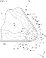
- FIG. 5 is a plan view (top view) when a vicinity (predetermined corner portion, an edge portion) of the cutting edge 3 of the cutting tool 10 is viewed in the insert axial direction.
- the cutting edge 3 has a V-shape in a plan view when the rake face 1 is viewed from a front surface.
- the cutting edge 3 includes a corner edge 3a having a protruded curved shape and a pair of straight edges 3b connected to both ends of the corner edge 3a and extending linearly.
- an XYZ orthogonal coordinate system (three-dimensional orthogonal coordinate system) is appropriately set in each drawing, and each configuration will be described.
- an extending direction of a bisector B of the cutting edge 3 having a V-shape will be referred to as a front-rear direction.
- the bisector B corresponds to a bisector of an angle of a central angle formed between the pair of straight edges 3b in the plan view.
- the front-rear direction corresponds to a Y-axis direction in each drawing.
- the bisector B is orthogonal to the insert center axis C. That is, the bisector B extends along a predetermined insert radial direction.
- a direction from the insert center axis C toward the corner edge 3a will be referred to as a front side (-Y side), and a direction from the corner edge 3a toward the insert center axis C will be referred to as a rear side (+Y side).
- a direction orthogonal to the bisector B will be referred to as a left-right direction.
- the left-right direction corresponds to an X-axis direction in each drawing.
- a direction from the bisector B toward a left side will be referred to as a left side (-X side)
- a direction from the bisector B toward a right side will be referred to as a right side (+X side) when the rake face 1 is viewed from the front surface.
- One in the left side and the right side may be rephrased as one side in the left-right direction, and the other may be rephrased as the other side in the left-right direction.
- a direction closer to the bisector B in the left-right direction will be referred to as an inside (central side), and a direction separated from the bisector B will be referred to as an outside.
- a direction orthogonal to the front-rear direction and the left-right direction will be referred to as an up-down direction.
- the up-down direction corresponds to a Z-axis direction in each drawing.
- a facing direction of the rake face 1 will be referred to as an upper side (+Z side)
- a direction opposite to the upper side will be referred to as a lower side (-Z side).
- the up-down direction corresponds to the insert axial direction.
- a predetermined corner portion (edge portion) of the cutting tool 10 is formed in a left-right symmetric shape in which the bisector B is set as a symmetry axis.
- the front side, the rear side, the left side, the right side, the upper side, and the lower side are merely terms for describing a relative positional relationship between the respective portions, and an actual disposition relationship or the like when a tool is used or the like may be a disposition relationship or the like other than the disposition relationship indicated by the above-described terms.
- the rake face 1 is disposed inside the cutting edge 3 on a plate surface of the cutting tool 10 which faces the insert axial direction. Specifically, the rake face 1 is disposed adjacent to the cutting edge 3 inside the cutting edge 3 in the insert radial direction.
- the rake face 1 includes a land 15 and an inclined surface 16.
- the land 15 is a portion directly connected to the cutting edge 3 in the rake face 1.
- the land 15 extends along the cutting edge 3, and has a V-shape as a whole in a plan view shown in FIG. 5 .
- the land 15 extends while being inclined toward the lower side as the land 15 is separated from the cutting edge 3 along a virtual plane (hereinafter, referred to as a tool reference plane Pr) passing through the cutting edge 3 and perpendicular to the up-down direction. That is, the land 15 has a rake angle of a positive angle (regular angle).
- the "rake angle” refers to an inclination angle in each portion (each component) of the rake face 1 with respect to the tool reference plane Pr.
- the inclined surface 16 is a portion disposed inside the land 15 in the rake face 1. That is, the inclined surface 16 is disposed farther separated from the cutting edge 3 than the land 15.
- the inclined surface 16 is connected to the land 15.
- the inclined surface 16 extends along the cutting edge 3, and has a substantially V-shape as a whole in the plan view shown in FIG. 5 .
- the inclined surface 16 is inclined toward the lower side as the inclined surface 16 is separated from the cutting edge 3 in a direction orthogonal to the cutting edge 3. Therefore, the rake angle of the inclined surface 16 is a positive angle (regular angle).
- the rake angle of the inclined surface 16 is larger than the rake angle of the land 15 on a right angle side.
- the flank face 2 is disposed on an outer peripheral surface of the cutting tool 10 which faces the outside in the insert radial direction. Specifically, the flank face 2 is disposed over a portion facing the front side, the left side, and the right side in a predetermined corner portion in the outer peripheral surface of the cutting tool 10. The flank face 2 extends in the insert circumferential direction. The flank face 2 is disposed adjacent to the cutting edge 3 on a lower side of the cutting edge 3.
- the cutting tool 10 is a so-called negative insert of a double-sided type, and the flank face 2 is provided parallel to the insert center axis C. That is, a clearance angle of the flank face 2 is set to 0°.
- the "clearance angle” refers to an inclination angle of the flank face 2 with respect to a virtual straight-line (not shown) passing through the cutting edge 3 and orthogonal to the tool reference plane Pr in a cross-sectional view perpendicular to the cutting edge 3.
- the flank face 2 has a corner flank face 21 and a pair of straight flank faces 22 connected to both ends of the corner flank face 21 in the insert circumferential direction.
- the corner flank face 21 is a portion connected to the corner edge 3a in the flank face 2.
- the corner flank face 21 is disposed in a portion in the flank face 2 which faces the front side (-Y side).
- the corner flank face 21 is disposed in a front end portion of the flank face 2, and has a protruded curved face shape protruding toward the front side.
- the straight flank face 22 is a portion connected to the straight edge 3b in the flank face 2.
- the straight flank face 22 has a planar shape.
- One straight flank face 22 in the pair of straight flank faces 22 is disposed in a portion of the flank face 2 which faces the left side (-X side).
- One straight flank face 22 is connected to one straight edge 3b located on the left side of the bisector B in the pair of straight edges 3b.
- One straight flank face 22 extends along the one straight edge 3b.
- the other straight flank face 22 is disposed in a portion in the flank face 2 which faces the right side (+X side).
- the other straight flank face 22 is connected to the other straight edge 3b located on the right side of the bisector B in the pair of straight edges 3b.
- the other straight flank face 22 extends along the other straight edge 3b.
- the cutting edge 3 includes the corner edge 3a and the pair of straight edges 3b.
- the corner edge 3a in the cutting edge 3 has a curved shape protruding toward the front side (-Y side), and specifically, has a protruded arc shape.
- the corner edge 3a extends along a surface direction of the tool reference plane Pr perpendicular to the up-down direction.
- the corner edge 3a as a whole is included in a plane of the tool reference plane Pr.
- the corner edge 3a may be provided to be inclined with respect to the tool reference plane Pr.
- the pair of straight edges 3b is connected to both ends in an edge length direction in which the corner edge 3a extends. In the plan view shown in FIG. 5 , each of the straight edges 3b extends along each tangent line in contact with both ends of the corner edge 3a.
- One straight edge 3b in the pair of straight edges 3b is connected to one end (left end) of the corner edge 3a in the edge length direction.
- the one straight edge 3b linearly extends toward the left side (-X side) as the one straight edge 3b faces the rear side (+Y side) from a portion connected to the corner edge 3a.
- the one straight edge 3b extends while being inclined toward the lower side as the one straight edge 3b is separated from the portion connected to the corner edge 3a along the edge length direction in which the first straight edge 3b extends.
- the other straight edge 3b in the pair of straight edges 3b is connected to the other end (right end) of the corner edge 3a in the edge length direction.
- the other straight edge 3b linearly extends toward the right side (+X side) as the other straight edge 3b faces the rear side (+Y side) from the portion connected to the corner edge 3a.
- the other straight edge 3b extends while being inclined toward the lower side as the other straight edge 3b is separated from the portion connected to the corner edge 3a in the edge length direction in which the other straight edge 3b extends.
- the chip breaker 4 is disposed inside the cutting edge 3 in a plate surface on which the cutting tool 10 faces the insert axial direction. At least a portion of the chip breaker 4 is disposed on the rake face 1.
- the chip breaker 4 includes a first protruded portion 41, a second protruded portion 42, a third protruded portion 43, and a breaker wall 44.
- the first protruded portion 41 protrudes to the upper side from the rake face 1. Specifically, the first protruded portion 41 includes a portion disposed on the inclined surface 16 in the rake face 1. The first protruded portion 41 is formed in a protruded shape to form a portion of a sphere.
- the front surface (protruded surface) of the first protruded portion 41 has a protruded curved face shape, and specifically, is formed in a protruded spherical surface shape to form a portion of a spherical surface.
- the first protruded portion 41 is located on the bisector B.
- the first protruded portion 41 is disposed to overlap a center O of a curvature radius of the corner edge 3a. More specifically, in the present embodiment, in the plan view, a top portion 41a of the first protruded portion 41 located in an upper end portion overlaps the center O of the curvature radius of the corner edge 3a.
- the top portion 41a of the first protruded portion 41 is disposed on the upper side of the tool reference plane Pr passing through the corner edge 3a located on the uppermost side in the cutting edge 3 and widened in a direction perpendicular to the up-down direction. That is, the first protruded portion 41 protrudes to the upper side of the cutting edge 3.
- a front side end portion in the first protruded portion 41 is located on the lower side of the corner edge 3a.
- both ends in the first protruded portion 41 in the left-right direction are located on the lower side of the corner edge 3a.
- the second protruded portion 42 protrudes to the upper side from the rake face 1, and is disposed on the rear side of the first protruded portion 41.
- the second protruded portion 42 includes a portion disposed on the inclined surface 16 in the rake face 1.
- the second protruded portion 42 extends toward the front side as the second protruded portion 42 is separated from the bisector B in the left-right direction.
- the second protruded portion 42 is formed in a rib shape.
- the front surface of the second protruded portion 42 has a protruded curved face shape.
- the pair of second protruded portions 42 is provided on the left side (-X side) and the right side (+X side) of the bisector B.
- the pair of second protruded portions 42 is formed in a mutually left-right symmetric shape while the bisector B is set as the symmetry axis. Therefore, hereinafter, any one in the pair of second protruded portions 42 will be mainly described.
- An end portion of the second protruded portion 42 on the inner side (central side) in the left-right direction is located on the bisector B.
- a width dimension of an inner side portion in the second protruded portion 42 in the left-right direction increases as the inner side portion faces the outer side in the left-right direction from the bisector B.
- a width dimension of an outer side portion in the second protruded portion 42 in the left-right direction decreases as the outer side portion faces the outer side in the left-right direction.
- the second protruded portion 42 includes a portion (outer end portion in the left-right direction) located outside the center O of the curvature radius of the corner edge 3a in the left-right direction and a portion (inner end portion in the left-right direction) located on the rear side of the center O.
- the second protruded portion 42 is disposed to surround the center O of the curvature radius of the corner edge 3a and the first protruded portion 41 from the outside and the rear side in the left-right direction.
- a reference numeral L indicated by a straight line of a one-dot chain line in FIG. 5 represents an extending direction of the ridgeline 42a of the second protruded portion 42. That is, the ridgeline 42a of the second protruded portion 42 extends linearly. In the plan view shown in FIG. 5 , for example, an angle ⁇ formed between the ridgeline 42a of the second protruded portion 42 and the bisector B is 30° or larger and 60° or smaller.
- the ridgeline 42a of the second protruded portion 42 extends to the upper side as the ridgeline 42a faces the inner end portion from the outer end portion of the second protruded portion 42 in the left-right direction along the extending direction of the ridgeline 42a. That is, in the second protruded portion 42, the amount of protruded to the upper side increases as the second protruded portion 42 is closer to the bisector B along the extending direction of the ridgeline 42a.
- the second protruded portion 42 has a portion located on the upper side of the tool reference plane Pr passing through the corner edge 3a located on an uppermost side in the cutting edge 3 and widened in a direction perpendicular to the up-down direction. That is, the second protruded portion 42 protrudes to the upper side of the cutting edge 3.
- the second protruded portion 42 has a portion disposed on the upper side of the top portion 41a located on the uppermost side in the first protruded portion 41. That is, the second protruded portion 42 protrudes to the upper side of the first protruded portion 41.
- the third protruded portion 43 protrudes to the upper side from the rake face 1, and is disposed on the front side of the first protruded portion 41. Specifically, the third protruded portion 43 is disposed on the inclined surface 16 in the rake face 1.
- the third protruded portion 43 is formed in a protruded shape to form a portion of a sphere.
- the front surface (protruded surface) of the third protruded portion 43 is formed in a protruded curved face shape, and specifically, is formed in a protruded spherical surface shape to form a portion of a spherical surface.
- the curvature radius of the protruded surface (protruded curved face) of the third protruded portion 43 is smaller than the curvature radius of the protruded surface (protruded curved face) of the first protruded portion 41.
- the third protruded portion 43 is located on the bisector B. In addition, in the plan view, the third protruded portion 43 is disposed on the front side of the center O of the curvature radius of the corner edge 3a.
- the third protruded portion 43 as a whole is disposed on the lower side of the tool reference plane Pr widened in a direction passing through the corner edge 3a and perpendicular to the up-down direction. That is, the third protruded portion 43 is located on the lower side of at least the corner edge 3a in the cutting edge 3.
- the top portion 43a located on the uppermost side in the third protruded portion 43 is located on the lower side of the top portion 41a located on the uppermost side in the first protruded portion 41. That is, the height of the third protruded portion 43 is lower than the height of the first protruded portion 41 in the up-down direction.
- the breaker wall 44 is disposed on the rear side of the second protruded portion 42, and protrudes to the upper side of the second protruded portion 42.
- the breaker wall 44 includes a wall surface located on the upper side of the second protruded portion 42 and facing the front side and the left-right direction.
- the breaker wall 44 includes a conical surface portion 44a disposed adjacent to the rear side of the second protruded portion 42, and a wavy surface portion 44b disposed on the rear side of the conical surface portion 44a.
- the conical surface portion 44a has a conical surface shape protruded toward the front side.
- the conical surface portion 44a has a protruded curved face shape facing the front side, the left side, and the right side, and extends in the insert circumferential direction.
- the conical surface portion 44a is provided such that a diameter decreases toward the upper side.
- the wavy surface portion 44b is connected to the outer side end portion of the conical surface portion 44a in the left-right direction, and extends toward the outer side in the left-right direction as the wavy surface portion 44b faces the rear side.
- a pair of the wavy surface portions 44b is provided on the left side (-X side) and the right side (+X side) of the bisector B.
- the pair of wavy surface portions 44b is formed in a mutually left-right symmetric shape while the bisector B is set as the symmetry axis. Therefore, hereinafter, any one in the pair of wavy surface portions 44b will be mainly described.
- the wavy surface portion 44b is formed in a waveform to alternately face the inner side (central side) and the outer side in the left-right direction (to meander) as the wavy surface portion 44b is separated from the portion connected to the conical surface portion 44a along the extending direction of the wavy surface portion 44b.
- the wavy surface portion 44b is inclined to be closer to the bisector B as the wavy surface portion 44b faces the upper side.
- the chip breaker 4 further includes a valley portion 45 disposed between the first protruded portion 41 and the second protruded portion 42.
- the valley portion 45 is located in a boundary portion between the first protruded portion 41 and the second protruded portion 42, and has a groove shape recessed to the lower side.
- the valley portion 45 extends toward the front side as the valley portion 45 is separated from the bisector B in the left-right direction.
- the extending direction of the valley portion 45 is substantially the same as the extending direction of the ridgeline 42a of the second protruded portion 42.
- a pair of the valley portion 45 is provided on the left side (-X side) and the right side (+X side) of the bisector B.
- the pair of valley portions 45 is formed in a mutually left-right symmetric shape while the bisector B is set as the symmetry axis. Therefore, hereinafter, any one in the pair of valley portions 45 will be mainly described.
- the inner side (central side) end portion of the valley portion 45 in the left-right direction is located on the bisector B.
- the outer side end portion of the valley portion 45 in the left-right direction is connected to the inclined surface 16 of the rake face 1.
- the position of a valley bottom (flute bottom) in the up-down direction is lowered as the valley portion 45 faces an outer end portion from an inner end portion in the left-right direction along the extending direction of the valley portion 45.
- the valley bottom of the valley portion 45 is located on the upper side of the tool reference plane Pr passing through the cutting edge 3 and widened in a direction perpendicular to the up-down direction.
- the valley bottom of the valley portion 45 is located on the lower side of the tool reference plane Pr (that is, the lower side of the cutting edge 3) (not shown).
- the fitting hole 5 penetrates the cutting tool 10 in the insert axial direction, and is open to a pair of plate surfaces (front surface and back surface) of the cutting tool 10.
- the fitting hole 5 has a circular hole shape in which the insert center axis C is set as the center.
- a clamp piece, a clamp screw, or the like for fixing the cutting tool 10 to the insert mounting seat of the holder is inserted into the fitting hole 5.
- chips generated by the cutting edge 3 come into contact with the first protruded portion 41 and the second protruded portion 42 of the chip breaker 4. That is, the chips are compressed and curled to be pinched between the two protruded portions 41 and 42 aligned in the front-rear direction while being two-point supported by the two protruded portions 41 and 42. Therefore, thick chips can be stably curled, and chip disposal performance is satisfactorily maintained.
- the second protruded portion 42 extends toward the front side as the second protruded portion 42 is separated from the bisector B in the left-right direction.
- the extending direction of the second protruded portion 42 is substantially the same as the direction in which the chips generated by the cutting edge 3 flow out on the rake face 1. Therefore, the chips are stably curled by the two protruded portions 41 and 42 while being guided in an outflow direction by the second protruded portion 42. Therefore, the chip disposal performance is more stable.
- the chips generated by the cutting edge 3 come into contact with the third protruded portion 43 located on the front side in the chip breaker 4. Therefore, spreading of thin chips is suppressed, and the thin chips are stably broken.
- the height of the third protruded portion 43 is lower than the height of the first protruded portion 41 in the up-down direction, that is, the amount of protruded from the rake face 1 is small. Therefore, excessive curling of the chips in contact with the third protruded portion 43 is suppressed, and collision of the chips with the machined surface of the workpiece is suppressed. In this manner, machined surface accuracy is satisfactorily maintained.
- chip disposal performance can be satisfactorily maintained regardless of the depth of cut or the like, and machined surface accuracy can be stably improved.
- the second protruded portion 42 protrudes to the upper side of the first protruded portion 41.
- the chips flowing out while being two-point supported by the first protruded portion 41 and the second protruded portion 42 are spirally rolled and stably curled due to a height difference between the protruded portions 41 and 42.
- the chip disposal performance is more stably improved.
- the chip breaker 4 includes the breaker wall 44 disposed on the rear side of the second protruded portion 42 and protruded to the upper side of the second protruded portion 42.
- the chips passing over the second protruded portion 42 to the rear side collide with the breaker wall 44, and thus, chip disposal is stably performed.
- the chip disposal is satisfactorily performed in such a manner that the chips passing over the second protruded portion 42 come into contact with the conical surface portion 44a.
- the third protruded portion 43 is located on the lower side of at least the corner edge 3a in the cutting edge 3.
- the third protruded portion 43 is disposed on the lower side of the corner edge 3a. Therefore, in a case of shallow cutting, excessive curling of the chips generated by the corner edge 3a and coming into contact with the third protruded portion 43 is stably suppressed. In this manner, the machined surface accuracy is stably improved.
- the third protruded portion 43 is located on the front side of the center O of the curvature radius of the corner edge 3a in a plan view.
- the chips generated by the corner edge 3a in a case of shallow cutting are stably brought into contact with the third protruded portion 43.
- Chip disposal performance of the third protruded portion 43 is more stably achieved.
- the first protruded portion 41 overlaps the center O of the curvature radius of the corner edge 3a in a plan view.
- the chips generated in the vicinity of a boundary between the corner edge 3a and the straight edge 3b in the cutting edge 3 or in the corner edge 3a are stably brought into contact with the first protruded portion 41.
- the chip disposal performance of the first protruded portion 41 is more stably achieved.
- the angle ⁇ formed between the ridgeline 42a of the second protruded portion 42 and the bisector B is 30° or larger and 60° or smaller.
- the angle ⁇ is 30° or larger and 60° or smaller, the chip disposal performance of the second protruded portion 42 is more stably achieved regardless of the opening angle (angle formed between the pair of straight edges 3b) of the cutting edge 3 in the plan view, the tool posture during cutting, or the like.
- the outflow direction of the chips and the extending direction of the second protruded portion 42 may be significantly different from each other depending on the opening angle of the cutting edge 3, the tool posture during cutting, or the like. Accordingly, the chip disposal performance may be affected.
- the valley bottom (flute bottom) of the valley portion 45 is located on the lower side of the cutting edge 3.
- the depth of the valley portion 45 between the protruded portions 41 and 42 is largely secured in the outer side portion in the right-left direction with which the chips start to come into contact in the first protruded portion 41 and the second protruded portion 42, a chip curling function in two-point supporting of the two protruded portions 41 and 42 is more stable.
- the curling function by the two-point supporting is likely to be satisfactorily maintained.
- the rake angle of the land 15 of the rake face 1 is set to the positive angle (regular angle), but the present invention is not limited thereto.
- the rake angle of the land 15 may be set to 0° or a negative angle (irregular angle).
- the rake face 1 does not need to be provided with the land 15.
- the clearance angle of the flank face 2 is set to 0°, but the present invention is not limited thereto.
- the flank face 2 may be inclined toward the inside in the insert radial direction as the flank face 2 is separated from the cutting edge 3 in the insert axial direction. In this case, a predetermined clearance angle is assigned to the flank face 2.
- the cutting tool 10 is the double-sided type having the front-back inversion symmetric shape, but the present invention is not limited thereto.
- the cutting tool 10 may be a single-sided type which does not have the front-back inversion symmetric shape.
- the cutting tool 10 is formed of a single member made of cemented carbide, but the present invention is not limited thereto.
- the cutting tool 10 may include a base metal portion having a polygonal plate shape, and an edge portion fixed to a recessed portion located at a corner portion of the base metal portion.
- the base metal portion is made of cemented carbide, and for example, the edge portion is made of a cubic boron nitride (cBN) sintered body or a polycrystalline diamond (PCD) sintered body.
- cBN cubic boron nitride
- PCD polycrystalline diamond
- the rake face 1, the flank face 2, the cutting edge 3, and the chip breaker 4 are disposed in the edge portion.
- the fitting hole 5 is disposed in the base metal portion.
- the cutting tool 10 is the cutting insert, but the present invention is not limited thereto.
- the cutting tool according to the present invention may be any cutting tool as long as the cutting tool includes the rake face 1, the flank face 2, the cutting edge 3, and the chip breaker 4, and for example, the cutting tool may be a replaceable head member of the indexable cutter.
- the cutting tool may be a solid type (integrated) cutter or the like.
- the chip disposal performance can be satisfactorily maintained regardless of the depth of cut or the like, and the machined surface accuracy can be stably improved. Therefore, the present invention has industrial applicability.
Landscapes
- Engineering & Computer Science (AREA)
- Mechanical Engineering (AREA)
- Cutting Tools, Boring Holders, And Turrets (AREA)
Abstract
A cutting tool includes a rake face (1), a flank face (2), a cutting edge (3) disposed in a ridgeline portion where the rake face (1) and the flank face (2) are connected and having a V-shape in a plan view of which the rake face (1) is viewed from a front surface, and a chip breaker (4) disposed on the rake face (1). The chip breaker (4) includes a first protruded portion (41) configured to protrude to an upper side from the rake face (1), a second protruded portion (42) configured to protrude to the upper side from the rake face (1), disposed on a rear side of the first protruded portion (41), and extending toward a front side as the second protruded portion (42) is separated from a bisector of the cutting edge (3) in a left-right direction, and a third protruded portion (43) configured to protrude to the upper side from the rake face (1) and disposed on a front side of the first protruded portion (41). The first protruded portion (41) and the second protruded portion (42) further protrude to the upper side than the cutting edge (3), and the height of the third protruded portion (43) is lower than the height of the first protruded portion (41) in an up-down direction.
Description
- The present invention relates to a cutting tool.
- Priority is claimed on
Japanese Patent Application No. 2022-125283, filed on August 5, 2022 - In the related art, a cutting tool such as a cutting insert used when a cutting operation is performed on a workpiece such as metal is known (for example,
Patent Document 1 and Patent Document 2). - This type of the cutting tool includes a rake face, a flank face, a cutting edge disposed in a ridgeline portion where the rake face and the flank face are connected and having a V-shape in a plan view of which the rake face is viewed from a front surface, and a chip breaker disposed on the rake face.
-
- Patent Document 1:
Japanese Patent No. 6413516(B - Patent Document 2:
Japanese Patent No. 4967721(B - For example, when the distance from a corner edge (nose R) located at a tip portion of a cutting edge to a chip breaker is long, chips are less likely to collide with the chip breaker, and are likely to spread during shallow cutting for a small depth of cut. Consequently, chip disposal performance deteriorates.
- On the other hand, when the distance from the corner edge to the chip breaker is simply shortened, chips are excessively curled, and collide with a machined surface of the workpiece. Consequently, machined surface accuracy is degraded.
- One object of the present invention is to provide a cutting tool which can satisfactorily maintain chip disposal performance regardless of a depth of cut or the like and can stably improve machined surface accuracy.
- A cutting tool includes a rake face, a flank face, a cutting edge disposed in a ridgeline portion where the rake face and the flank face are connected and having a V-shape in a plan view of which the rake face is viewed from a front surface, and a chip breaker disposed on the rake face. An extending direction of a bisector of the cutting edge in the plan view is set as a front-rear direction, a direction orthogonal to the bisector in the plan view is set as a left-right direction, and a direction orthogonal to the front-rear direction and the left-right direction is set as an up-down direction. The chip breaker includes a first protruded portion configured to protrude to an upper side from the rake face, a second protruded portion configured to protrude to the upper side from the rake face, disposed on a rear side of the first protruded portion, and extending toward a front side as the second protruded portion is separated from the bisector in the left-right direction, and a third protruded portion configured to protrude to the upper side from the rake face and disposed on a front side of the first protruded portion. The first protruded portion and the second protruded portion further protrude to the upper side than the cutting edge, and the height of the third protruded portion is lower than the height of the first protruded portion in the up-down direction.
- In the cutting tool according to the present invention, for example, in a case of deep cutting (deep feeding) for a large depth of cut, chips generated by the cutting edge come into contact with the first protruded portion and the second protruded portion of the chip breaker. That is, the chips are compressed and curled to be pinched between the two protruded portions aligned in the front-rear direction while being two-point supported by the protruded portions. Therefore, thick chips can be stably curled, and chip disposal performance is satisfactorily maintained.
- Specifically, the second protruded portion extends toward a front side as the second protruded portion is separated from the bisector in the left-right direction. An extending direction of the second protruded portion is substantially the same as a direction in which the chips generated by the cutting edge flow out on the rake face. Therefore, the chips are stably curled by the two protruded portions while being guided in an outflow direction by the second protruded portion. Therefore, the chip disposal performance is more stable.
- In addition, during shallow cutting for a small depth of cut, the chips generated by the cutting edge come into contact with the third protruded portion located on the front side in the chip breaker. Therefore, spreading of thin chips is suppressed, and the thin chips are stably broken.
- Specifically, the height of the third protruded portion is lower than the height of the first protruded portion in the up-down direction, that is, in the the third protruded portion, the amount of protruded from the rake face is small. Therefore, excessive curling of the chips in contact with the third protruded portion is suppressed, and collision of the chips with a machined surface of a workpiece is suppressed. In this manner, machined surface accuracy is satisfactorily maintained.
- As described above, according to the present invention, the chip disposal performance can be satisfactorily maintained regardless of the depth of cut or the like, and the machined surface accuracy can be stably improved.
- In the cutting tool according to
Aspect 1, the second protruded portion further protrudes to the upper side than the first protruded portion. - In this case, the chips flowing out while being two-point supported by the first protruded portion and the second protruded portion are spirally rolled and stably curled due to a height difference between the protruded portions. The chip disposal performance is more stably improved.
- In the cutting tool according to
Aspect - In this case, the chips passing over the second protruded portion to the rear side collide with the breaker wall, and thus, chip disposal is stably performed.
- In the cutting tool according to any one of
Aspects 1 to 3, the cutting edge includes a corner edge having a protruded curved shape, and a pair of straight edges connected to both ends of the corner edge and each extending linearly, and the third protruded portion is located on a lower side of at least the corner edge in the cutting edge. - In this case, since the third protruded portion is disposed on a lower side of the corner edge, excessive curling of the chips generated by the corner edge and coming into contact with the third protruded portion is stably suppressed in a case of shallow cutting. In this manner, the machined surface accuracy is stably improved.
- In the cutting tool according to
Aspect 4, the third protruded portion is located on a front side of a center of a curvature radius of the corner edge in the plan view. - In this case, chips generated by the corner edge in a case of shallow cutting are stably brought into contact with the third protruded portion. Chip disposal performance of the third protruded portion is more stably achieved.
- In the cutting tool according to
Aspect - In this case, during cutting, chips generated in the vicinity of a boundary between the corner edge and the straight edge in the cutting edge or in the corner edge are stably brought into contact with the first protruded portion. The chip disposal performance of the first protruded portion is more stably achieved.
- In the cutting tool according to any one of
aspects 1 to 6, an angle formed between a ridgeline of the second protruded portion and the bisector in the plan view is 30° or larger and 60° or smaller. - When the angle is 30° or larger and 60° or smaller, the chip disposal performance of the second protruded portion is more stably achieved regardless of an opening angle (angle formed between the pair of straight edges) of the cutting edge in the plan view, a tool posture during cutting, or the like.
- When the angle is smaller than 30° or exceeds 60°, in some cases, the outflow direction of the chips and the extending direction of the second protruded portion may be significantly different from each other depending on the opening angle of the cutting edge, the tool posture during cutting, or the like. Accordingly, the chip disposal performance may be affected.
- According to the cutting tool in the aspect of the present invention, chip disposal performance can be satisfactorily maintained regardless of a depth of cut or the like, and machined surface accuracy can be stably improved.
-
- [
FIG. 1] FIG. 1 is a perspective view showing a cutting tool of the present embodiment. - [
FIG. 2] FIG. 2 is a plan view (top view) showing the cutting tool of the present embodiment. - [
FIG. 3] FIG. 3 is a side view showing the cutting tool of the present embodiment. - [
FIG. 4] FIG. 4 is a perspective view showing an enlarged portion IV inFIG. 1 . - [
FIG. 5] FIG. 5 is a plan view (top view) showing a portion of the cutting tool. - [
FIG. 6] FIG. 6 is a cross-sectional view showing a cross section taken along line VI-VI ofFIG. 5 . - [
FIG. 7] FIG. 7 is a cross-sectional view showing a cross section taken along line VII-VII inFIG. 5 . - [
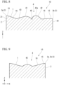
FIG. 8] FIG. 8 is a cross-sectional view showing a cross section taken along line VIII-VIII inFIG. 5 . - [
FIG. 9] FIG. 9 is a cross-sectional view showing a cross section taken along line IX-IX inFIG. 5 . - [
FIG. 10] FIG. 10 is a cross-sectional view showing a cross section taken along line X-X inFIG. 5 . - A cutting
tool 10 according to an embodiment of the present invention will be described with reference to the drawings. The cuttingtool 10 of the present embodiment is a cutting insert used in an indexable cutter that performs turning (cutting operation) on a workpiece made of metal, for example. In the present embodiment, in some cases, the cuttingtool 10 may be simply referred to as a tool or the like. - Although not particularly shown, the indexable cutter includes a holder and the cutting tool (cutting insert) 10. For example, the holder is made of a steel material. The holder has a recessed insert mounting seat disposed in a tip portion of the holder. For example, the cutting
tool 10 is made of cemented carbide. The cuttingtool 10 is integrally formed of a single member. The cuttingtool 10 is attached to the insert mounting seat to be attachable and detachable. - As shown in
FIGS. 1 to 3 , the cuttingtool 10 has a plate shape. In the present embodiment, the cuttingtool 10 has a polygonal plate shape, and specifically, has a quadrangular plate shape such as a rhomboid plate shape. More specifically, for example, the cuttingtool 10 of the present embodiment has an outer shape of a rhomboid insert (cutting insert) in conformity with a general ISO standard. However, without being limited thereto, the cuttingtool 10 may have a polygonal plate shape such as a triangular plate shape, a pentagonal plate shape, or a hexagonal plate shape. - The cutting
tool 10 has a polygonal plate shape in which an insert center axis C is set as a center, and a pair of plate surfaces (front surface and back surface) thereof faces an extending direction of the insert center axis C (insert axial direction). In the present specification, in some cases, a direction orthogonal to the insert center axis C may be referred to as an insert radial direction, and a turning direction around the insert center axis C may be referred to as an insert circumferential direction. In the insert radial direction, a direction closer to the insert center axis C is an inside of the insert radial direction, and a direction separated from the insert center axis C is an outer side of the insert radial direction. - In the present embodiment, the cutting
tool 10 has a front-back inversion symmetric shape in the insert axial direction. That is, the cuttingtool 10 is a so-called double-sided cutting insert. In addition, the cuttingtool 10 has a rotationally symmetric shape by 180° when the insert center axis C is set as the center. - The cutting
tool 10 includes arake face 1, aflank face 2, acutting edge 3 disposed in a ridgeline portion where therake face 1 and theflank face 2 are connected, achip breaker 4 disposed on therake face 1, and afitting hole 5. - The
rake face 1 and thechip breaker 4 are disposed on at least one plate surface (front surface) in a pair of plate surfaces having a polygonal shape of thecutting tool 10. Specifically, therake face 1 and thechip breaker 4 are disposed at predetermined corner portions (in the present embodiment, acute angle corner portions) in a plurality of corner portions of one plate surface. In addition, theflank face 2 is disposed on an outer peripheral surface of thecutting tool 10. Specifically, theflank face 2 is disposed at a predetermined corner portion (in the present embodiment, an acute angle corner portion) in the outer peripheral surface of thecutting tool 10. In addition, thecutting edge 3 is disposed in a ridgeline portion where one plate surface of thecutting tool 10 and the outer peripheral surface are connected. Specifically, thecutting edge 3 is disposed in a predetermined corner portion (in the present embodiment, an acute angle corner portion) in the ridgeline portion of thecutting tool 10. - The predetermined corner portion of the
cutting tool 10 in which therake face 1, theflank face 2, thecutting edge 3, and thechip breaker 4 are disposed may be rephrased as an "edge portion". - In the present embodiment, the cutting
tool 10 has a front-back inversion symmetric shape and a rotationally symmetric shape by 180° around the insert center axis C. Therefore, four sets of therake face 1, theflank face 2, thecutting edge 3, and thechip breaker 4 are provided in four corner portions including two acute angle corner portions on one plate surface (front surface) side of thecutting tool 10 and two acute angle corner portions on the other plate surface (back surface) side of thecutting tool 10. In addition, onefitting hole 5 is provided in thecutting tool 10. -
FIG. 2 is a plan view (top view) when thecutting tool 10 is viewed in the insert axial direction. In addition,FIG. 5 is a plan view (top view) when a vicinity (predetermined corner portion, an edge portion) of thecutting edge 3 of thecutting tool 10 is viewed in the insert axial direction. As shown inFIGS. 2 and5 , thecutting edge 3 has a V-shape in a plan view when therake face 1 is viewed from a front surface. Specifically, thecutting edge 3 includes acorner edge 3a having a protruded curved shape and a pair ofstraight edges 3b connected to both ends of thecorner edge 3a and extending linearly. - In the present embodiment, an XYZ orthogonal coordinate system (three-dimensional orthogonal coordinate system) is appropriately set in each drawing, and each configuration will be described.
- In a plan view of the
cutting tool 10 shown inFIG. 5 , an extending direction of a bisector B of thecutting edge 3 having a V-shape will be referred to as a front-rear direction. Specifically, the bisector B corresponds to a bisector of an angle of a central angle formed between the pair ofstraight edges 3b in the plan view. The front-rear direction corresponds to a Y-axis direction in each drawing. In the present embodiment, the bisector B is orthogonal to the insert center axis C. That is, the bisector B extends along a predetermined insert radial direction. In the front-rear direction, a direction from the insert center axis C toward thecorner edge 3a will be referred to as a front side (-Y side), and a direction from thecorner edge 3a toward the insert center axis C will be referred to as a rear side (+Y side). - In addition, in the plan view of the
cutting tool 10 shown inFIG. 5 , a direction orthogonal to the bisector B will be referred to as a left-right direction. The left-right direction corresponds to an X-axis direction in each drawing. In the left-right direction, as shown inFIG. 5 , a direction from the bisector B toward a left side will be referred to as a left side (-X side), and a direction from the bisector B toward a right side will be referred to as a right side (+X side) when therake face 1 is viewed from the front surface. One in the left side and the right side may be rephrased as one side in the left-right direction, and the other may be rephrased as the other side in the left-right direction. - In addition, a direction closer to the bisector B in the left-right direction will be referred to as an inside (central side), and a direction separated from the bisector B will be referred to as an outside.
- In addition, a direction orthogonal to the front-rear direction and the left-right direction will be referred to as an up-down direction. The up-down direction corresponds to a Z-axis direction in each drawing. In the up-down direction, a facing direction of the
rake face 1 will be referred to as an upper side (+Z side), and a direction opposite to the upper side will be referred to as a lower side (-Z side). In the present embodiment, the up-down direction corresponds to the insert axial direction. - As shown in
FIG. 5 , in the present embodiment, a predetermined corner portion (edge portion) of thecutting tool 10 is formed in a left-right symmetric shape in which the bisector B is set as a symmetry axis. - In the present embodiment, the front side, the rear side, the left side, the right side, the upper side, and the lower side are merely terms for describing a relative positional relationship between the respective portions, and an actual disposition relationship or the like when a tool is used or the like may be a disposition relationship or the like other than the disposition relationship indicated by the above-described terms.
- As shown in
FIGS. 4 and5 , therake face 1 is disposed inside thecutting edge 3 on a plate surface of thecutting tool 10 which faces the insert axial direction. Specifically, therake face 1 is disposed adjacent to thecutting edge 3 inside thecutting edge 3 in the insert radial direction. Therake face 1 includes aland 15 and aninclined surface 16. - The
land 15 is a portion directly connected to thecutting edge 3 in therake face 1. Theland 15 extends along thecutting edge 3, and has a V-shape as a whole in a plan view shown inFIG. 5 . As shown in respective cross-sectional views (vertical cross-sectional views) inFIGS. 6 and 7 , in the present embodiment, theland 15 extends while being inclined toward the lower side as theland 15 is separated from thecutting edge 3 along a virtual plane (hereinafter, referred to as a tool reference plane Pr) passing through thecutting edge 3 and perpendicular to the up-down direction. That is, theland 15 has a rake angle of a positive angle (regular angle). - In the present embodiment, the "rake angle" refers to an inclination angle in each portion (each component) of the
rake face 1 with respect to the tool reference plane Pr. - As shown in
FIGS. 4 and5 , theinclined surface 16 is a portion disposed inside theland 15 in therake face 1. That is, theinclined surface 16 is disposed farther separated from thecutting edge 3 than theland 15. Theinclined surface 16 is connected to theland 15. Theinclined surface 16 extends along thecutting edge 3, and has a substantially V-shape as a whole in the plan view shown inFIG. 5 . In the plan view, theinclined surface 16 is inclined toward the lower side as theinclined surface 16 is separated from thecutting edge 3 in a direction orthogonal to thecutting edge 3. Therefore, the rake angle of theinclined surface 16 is a positive angle (regular angle). - As shown in
FIGS. 6 to 10 , the rake angle of theinclined surface 16 is larger than the rake angle of theland 15 on a right angle side. - As shown in
FIG. 4 , theflank face 2 is disposed on an outer peripheral surface of thecutting tool 10 which faces the outside in the insert radial direction. Specifically, theflank face 2 is disposed over a portion facing the front side, the left side, and the right side in a predetermined corner portion in the outer peripheral surface of thecutting tool 10. Theflank face 2 extends in the insert circumferential direction. Theflank face 2 is disposed adjacent to thecutting edge 3 on a lower side of thecutting edge 3. - In the present embodiment, the cutting
tool 10 is a so-called negative insert of a double-sided type, and theflank face 2 is provided parallel to the insert center axis C. That is, a clearance angle of theflank face 2 is set to 0°. - In the present embodiment, for example, as shown in
FIG. 6 , the "clearance angle" refers to an inclination angle of theflank face 2 with respect to a virtual straight-line (not shown) passing through thecutting edge 3 and orthogonal to the tool reference plane Pr in a cross-sectional view perpendicular to thecutting edge 3. - As shown in
FIGS. 4 and5 , theflank face 2 has acorner flank face 21 and a pair of straight flank faces 22 connected to both ends of thecorner flank face 21 in the insert circumferential direction. - The
corner flank face 21 is a portion connected to thecorner edge 3a in theflank face 2. Thecorner flank face 21 is disposed in a portion in theflank face 2 which faces the front side (-Y side). Specifically, thecorner flank face 21 is disposed in a front end portion of theflank face 2, and has a protruded curved face shape protruding toward the front side. - The
straight flank face 22 is a portion connected to thestraight edge 3b in theflank face 2. Thestraight flank face 22 has a planar shape. - One
straight flank face 22 in the pair of straight flank faces 22 is disposed in a portion of theflank face 2 which faces the left side (-X side). Onestraight flank face 22 is connected to onestraight edge 3b located on the left side of the bisector B in the pair ofstraight edges 3b. Onestraight flank face 22 extends along the onestraight edge 3b. - In the pair of straight flank faces 22, the other
straight flank face 22 is disposed in a portion in theflank face 2 which faces the right side (+X side). The otherstraight flank face 22 is connected to the otherstraight edge 3b located on the right side of the bisector B in the pair ofstraight edges 3b. The otherstraight flank face 22 extends along the otherstraight edge 3b. - As described above, the
cutting edge 3 includes thecorner edge 3a and the pair ofstraight edges 3b. Thecorner edge 3a in thecutting edge 3 has a curved shape protruding toward the front side (-Y side), and specifically, has a protruded arc shape. In the present embodiment, thecorner edge 3a extends along a surface direction of the tool reference plane Pr perpendicular to the up-down direction. Thecorner edge 3a as a whole is included in a plane of the tool reference plane Pr. However, without being limited thereto, thecorner edge 3a may be provided to be inclined with respect to the tool reference plane Pr. - The pair of
straight edges 3b is connected to both ends in an edge length direction in which thecorner edge 3a extends. In the plan view shown inFIG. 5 , each of thestraight edges 3b extends along each tangent line in contact with both ends of thecorner edge 3a. - One
straight edge 3b in the pair ofstraight edges 3b is connected to one end (left end) of thecorner edge 3a in the edge length direction. The onestraight edge 3b linearly extends toward the left side (-X side) as the onestraight edge 3b faces the rear side (+Y side) from a portion connected to thecorner edge 3a. In the present embodiment, the onestraight edge 3b extends while being inclined toward the lower side as the onestraight edge 3b is separated from the portion connected to thecorner edge 3a along the edge length direction in which the firststraight edge 3b extends. - The other
straight edge 3b in the pair ofstraight edges 3b is connected to the other end (right end) of thecorner edge 3a in the edge length direction. The otherstraight edge 3b linearly extends toward the right side (+X side) as the otherstraight edge 3b faces the rear side (+Y side) from the portion connected to thecorner edge 3a. In the present embodiment, the otherstraight edge 3b extends while being inclined toward the lower side as the otherstraight edge 3b is separated from the portion connected to thecorner edge 3a in the edge length direction in which the otherstraight edge 3b extends. - As shown in
FIGS. 4 and5 , thechip breaker 4 is disposed inside thecutting edge 3 in a plate surface on which thecutting tool 10 faces the insert axial direction. At least a portion of thechip breaker 4 is disposed on therake face 1. Thechip breaker 4 includes a first protrudedportion 41, a second protrudedportion 42, a third protrudedportion 43, and abreaker wall 44. - The first protruded
portion 41 protrudes to the upper side from therake face 1. Specifically, the first protrudedportion 41 includes a portion disposed on theinclined surface 16 in therake face 1. The first protrudedportion 41 is formed in a protruded shape to form a portion of a sphere. The front surface (protruded surface) of the first protrudedportion 41 has a protruded curved face shape, and specifically, is formed in a protruded spherical surface shape to form a portion of a spherical surface. - In the plan view shown in
FIG. 5 , the first protrudedportion 41 is located on the bisector B. In addition, in the plan view, the first protrudedportion 41 is disposed to overlap a center O of a curvature radius of thecorner edge 3a. More specifically, in the present embodiment, in the plan view, atop portion 41a of the first protrudedportion 41 located in an upper end portion overlaps the center O of the curvature radius of thecorner edge 3a. - As shown in
FIG. 6 , thetop portion 41a of the first protrudedportion 41 is disposed on the upper side of the tool reference plane Pr passing through thecorner edge 3a located on the uppermost side in thecutting edge 3 and widened in a direction perpendicular to the up-down direction. That is, the first protrudedportion 41 protrudes to the upper side of thecutting edge 3. - In addition, as shown in
FIG. 6 , a front side end portion in the first protrudedportion 41 is located on the lower side of thecorner edge 3a. In addition, as shown inFIG. 5 andFIG. 7 showing a cross section taken along line VII-VII inFIG. 5 , both ends in the first protrudedportion 41 in the left-right direction (inFIG. 7 , a left side end portion of the first protruded portion 41) are located on the lower side of thecorner edge 3a. - As shown in
FIGS. 4 and5 , the second protrudedportion 42 protrudes to the upper side from therake face 1, and is disposed on the rear side of the first protrudedportion 41. Specifically, the second protrudedportion 42 includes a portion disposed on theinclined surface 16 in therake face 1. The second protrudedportion 42 extends toward the front side as the second protrudedportion 42 is separated from the bisector B in the left-right direction. The second protrudedportion 42 is formed in a rib shape. The front surface of the second protrudedportion 42 has a protruded curved face shape. - The pair of second protruded
portions 42 is provided on the left side (-X side) and the right side (+X side) of the bisector B. The pair of second protrudedportions 42 is formed in a mutually left-right symmetric shape while the bisector B is set as the symmetry axis. Therefore, hereinafter, any one in the pair of second protrudedportions 42 will be mainly described. - An end portion of the second protruded
portion 42 on the inner side (central side) in the left-right direction is located on the bisector B. In the plan view shown inFIG. 5 , a width dimension of an inner side portion in the second protrudedportion 42 in the left-right direction increases as the inner side portion faces the outer side in the left-right direction from the bisector B. In addition, in the plan view, a width dimension of an outer side portion in the second protrudedportion 42 in the left-right direction decreases as the outer side portion faces the outer side in the left-right direction. - In addition, in the plan view shown in
FIG. 5 , the second protrudedportion 42 includes a portion (outer end portion in the left-right direction) located outside the center O of the curvature radius of thecorner edge 3a in the left-right direction and a portion (inner end portion in the left-right direction) located on the rear side of the center O. The second protrudedportion 42 is disposed to surround the center O of the curvature radius of thecorner edge 3a and the first protrudedportion 41 from the outside and the rear side in the left-right direction. - A reference numeral L indicated by a straight line of a one-dot chain line in
FIG. 5 represents an extending direction of theridgeline 42a of the second protrudedportion 42. That is, theridgeline 42a of the second protrudedportion 42 extends linearly. In the plan view shown inFIG. 5 , for example, an angle α formed between theridgeline 42a of the second protrudedportion 42 and the bisector B is 30° or larger and 60° or smaller. - As shown in
FIG. 4 , theridgeline 42a of the second protrudedportion 42 extends to the upper side as theridgeline 42a faces the inner end portion from the outer end portion of the second protrudedportion 42 in the left-right direction along the extending direction of theridgeline 42a. That is, in the second protrudedportion 42, the amount of protruded to the upper side increases as the second protrudedportion 42 is closer to the bisector B along the extending direction of theridgeline 42a. - As shown in
FIG. 6 , the second protrudedportion 42 has a portion located on the upper side of the tool reference plane Pr passing through thecorner edge 3a located on an uppermost side in thecutting edge 3 and widened in a direction perpendicular to the up-down direction. That is, the second protrudedportion 42 protrudes to the upper side of thecutting edge 3. - As shown in
FIGS. 6 and 7 , the second protrudedportion 42 has a portion disposed on the upper side of thetop portion 41a located on the uppermost side in the first protrudedportion 41. That is, the second protrudedportion 42 protrudes to the upper side of the first protrudedportion 41. - As shown in
FIGS. 4 and5 , the third protrudedportion 43 protrudes to the upper side from therake face 1, and is disposed on the front side of the first protrudedportion 41. Specifically, the third protrudedportion 43 is disposed on theinclined surface 16 in therake face 1. The third protrudedportion 43 is formed in a protruded shape to form a portion of a sphere. The front surface (protruded surface) of the third protrudedportion 43 is formed in a protruded curved face shape, and specifically, is formed in a protruded spherical surface shape to form a portion of a spherical surface. In the present embodiment, the curvature radius of the protruded surface (protruded curved face) of the third protrudedportion 43 is smaller than the curvature radius of the protruded surface (protruded curved face) of the first protrudedportion 41. - In the plan view shown in
FIG. 5 , the third protrudedportion 43 is located on the bisector B. In addition, in the plan view, the third protrudedportion 43 is disposed on the front side of the center O of the curvature radius of thecorner edge 3a. - As shown in
FIG. 6 , the third protrudedportion 43 as a whole is disposed on the lower side of the tool reference plane Pr widened in a direction passing through thecorner edge 3a and perpendicular to the up-down direction. That is, the third protrudedportion 43 is located on the lower side of at least thecorner edge 3a in thecutting edge 3. - In addition, the
top portion 43a located on the uppermost side in the third protrudedportion 43 is located on the lower side of thetop portion 41a located on the uppermost side in the first protrudedportion 41. That is, the height of the third protrudedportion 43 is lower than the height of the first protrudedportion 41 in the up-down direction. - As shown in
FIGS. 4 to 6 , thebreaker wall 44 is disposed on the rear side of the second protrudedportion 42, and protrudes to the upper side of the second protrudedportion 42. Thebreaker wall 44 includes a wall surface located on the upper side of the second protrudedportion 42 and facing the front side and the left-right direction. In the present embodiment, thebreaker wall 44 includes aconical surface portion 44a disposed adjacent to the rear side of the second protrudedportion 42, and awavy surface portion 44b disposed on the rear side of theconical surface portion 44a. - The
conical surface portion 44a has a conical surface shape protruded toward the front side. Theconical surface portion 44a has a protruded curved face shape facing the front side, the left side, and the right side, and extends in the insert circumferential direction. Theconical surface portion 44a is provided such that a diameter decreases toward the upper side. - As shown in
FIG. 5 , thewavy surface portion 44b is connected to the outer side end portion of theconical surface portion 44a in the left-right direction, and extends toward the outer side in the left-right direction as thewavy surface portion 44b faces the rear side. A pair of thewavy surface portions 44b is provided on the left side (-X side) and the right side (+X side) of the bisector B. The pair ofwavy surface portions 44b is formed in a mutually left-right symmetric shape while the bisector B is set as the symmetry axis. Therefore, hereinafter, any one in the pair ofwavy surface portions 44b will be mainly described. - The
wavy surface portion 44b is formed in a waveform to alternately face the inner side (central side) and the outer side in the left-right direction (to meander) as thewavy surface portion 44b is separated from the portion connected to theconical surface portion 44a along the extending direction of thewavy surface portion 44b. In addition, thewavy surface portion 44b is inclined to be closer to the bisector B as thewavy surface portion 44b faces the upper side. - As shown in
FIGS. 4 and5 , thechip breaker 4 further includes avalley portion 45 disposed between the first protrudedportion 41 and the second protrudedportion 42. Thevalley portion 45 is located in a boundary portion between the first protrudedportion 41 and the second protrudedportion 42, and has a groove shape recessed to the lower side. As shown inFIG. 5 , thevalley portion 45 extends toward the front side as thevalley portion 45 is separated from the bisector B in the left-right direction. The extending direction of thevalley portion 45 is substantially the same as the extending direction of theridgeline 42a of the second protrudedportion 42. - A pair of the
valley portion 45 is provided on the left side (-X side) and the right side (+X side) of the bisector B. The pair ofvalley portions 45 is formed in a mutually left-right symmetric shape while the bisector B is set as the symmetry axis. Therefore, hereinafter, any one in the pair ofvalley portions 45 will be mainly described. - The inner side (central side) end portion of the
valley portion 45 in the left-right direction is located on the bisector B. The outer side end portion of thevalley portion 45 in the left-right direction is connected to theinclined surface 16 of therake face 1. As shown inFIGS. 6 to 8 , in thevalley portion 45, the position of a valley bottom (flute bottom) in the up-down direction is lowered as thevalley portion 45 faces an outer end portion from an inner end portion in the left-right direction along the extending direction of thevalley portion 45. - Specifically, as shown in
FIGS. 6 and 7 , in the inner side portion in thevalley portion 45 in the left-right direction, the valley bottom of thevalley portion 45 is located on the upper side of the tool reference plane Pr passing through thecutting edge 3 and widened in a direction perpendicular to the up-down direction. In addition, as shown inFIG. 8 , in the outer side portion (particularly, an outer end portion) in thevalley portion 45 in the left-right direction, the valley bottom of thevalley portion 45 is located on the lower side of the tool reference plane Pr (that is, the lower side of the cutting edge 3) (not shown). - As shown in
FIGS. 1 and2 , thefitting hole 5 penetrates thecutting tool 10 in the insert axial direction, and is open to a pair of plate surfaces (front surface and back surface) of thecutting tool 10. Thefitting hole 5 has a circular hole shape in which the insert center axis C is set as the center. Although not particularly shown, a clamp piece, a clamp screw, or the like for fixing thecutting tool 10 to the insert mounting seat of the holder is inserted into thefitting hole 5. - In the
cutting tool 10 of the present embodiment described above, for example, during deep cutting (deep feeding) for a large depth of cut, chips generated by thecutting edge 3 come into contact with the first protrudedportion 41 and the second protrudedportion 42 of thechip breaker 4. That is, the chips are compressed and curled to be pinched between the two protrudedportions portions - Specifically, the second protruded
portion 42 extends toward the front side as the second protrudedportion 42 is separated from the bisector B in the left-right direction. The extending direction of the second protrudedportion 42 is substantially the same as the direction in which the chips generated by thecutting edge 3 flow out on therake face 1. Therefore, the chips are stably curled by the two protrudedportions portion 42. Therefore, the chip disposal performance is more stable. - In addition, during shallow cutting for a small depth of cut, the chips generated by the
cutting edge 3 come into contact with the third protrudedportion 43 located on the front side in thechip breaker 4. Therefore, spreading of thin chips is suppressed, and the thin chips are stably broken. - Specifically, the height of the third protruded
portion 43 is lower than the height of the first protrudedportion 41 in the up-down direction, that is, the amount of protruded from therake face 1 is small. Therefore, excessive curling of the chips in contact with the third protrudedportion 43 is suppressed, and collision of the chips with the machined surface of the workpiece is suppressed. In this manner, machined surface accuracy is satisfactorily maintained. - As described above, according to the present embodiment, chip disposal performance can be satisfactorily maintained regardless of the depth of cut or the like, and machined surface accuracy can be stably improved.
- In addition, in the present embodiment, the second protruded
portion 42 protrudes to the upper side of the first protrudedportion 41. - In this case, the chips flowing out while being two-point supported by the first protruded
portion 41 and the second protrudedportion 42 are spirally rolled and stably curled due to a height difference between theprotruded portions - In addition, in the present embodiment, the
chip breaker 4 includes thebreaker wall 44 disposed on the rear side of the second protrudedportion 42 and protruded to the upper side of the second protrudedportion 42. - In this case, the chips passing over the second protruded
portion 42 to the rear side collide with thebreaker wall 44, and thus, chip disposal is stably performed. In the present embodiment, the chip disposal is satisfactorily performed in such a manner that the chips passing over the second protrudedportion 42 come into contact with theconical surface portion 44a. - In addition, in the present embodiment, the third protruded
portion 43 is located on the lower side of at least thecorner edge 3a in thecutting edge 3. - In this case, the third protruded
portion 43 is disposed on the lower side of thecorner edge 3a. Therefore, in a case of shallow cutting, excessive curling of the chips generated by thecorner edge 3a and coming into contact with the third protrudedportion 43 is stably suppressed. In this manner, the machined surface accuracy is stably improved. - In addition, in the present embodiment, the third protruded
portion 43 is located on the front side of the center O of the curvature radius of thecorner edge 3a in a plan view. - In this case, the chips generated by the
corner edge 3a in a case of shallow cutting are stably brought into contact with the third protrudedportion 43. Chip disposal performance of the third protrudedportion 43 is more stably achieved. - In addition, in the present embodiment, the first protruded
portion 41 overlaps the center O of the curvature radius of thecorner edge 3a in a plan view. - In this case, during cutting, the chips generated in the vicinity of a boundary between the
corner edge 3a and thestraight edge 3b in thecutting edge 3 or in thecorner edge 3a are stably brought into contact with the first protrudedportion 41. The chip disposal performance of the first protrudedportion 41 is more stably achieved. - In addition, in the present embodiment, in the plan view shown in
FIG. 5 , the angle α formed between theridgeline 42a of the second protrudedportion 42 and the bisector B is 30° or larger and 60° or smaller. - When the angle α is 30° or larger and 60° or smaller, the chip disposal performance of the second protruded
portion 42 is more stably achieved regardless of the opening angle (angle formed between the pair ofstraight edges 3b) of thecutting edge 3 in the plan view, the tool posture during cutting, or the like. - When the angle α is smaller than 30° or exceeds 60°, the outflow direction of the chips and the extending direction of the second protruded
portion 42 may be significantly different from each other depending on the opening angle of thecutting edge 3, the tool posture during cutting, or the like. Accordingly, the chip disposal performance may be affected. - In addition, in the present embodiment, in the outer side portion (particularly, the outer end portion) in the
valley portion 45 in the left-right direction, the valley bottom (flute bottom) of thevalley portion 45 is located on the lower side of thecutting edge 3. - In this case, the depth of the
valley portion 45 between theprotruded portions portion 41 and the second protrudedportion 42, a chip curling function in two-point supporting of the two protrudedportions portions - The present invention is not limited to the above-described embodiment, and for example, as will be described below, the configuration or the like can be changed within the scope not departing from the concept of the present invention.
- In the above-described embodiment, an example has been described in which the rake angle of the
land 15 of therake face 1 is set to the positive angle (regular angle), but the present invention is not limited thereto. The rake angle of theland 15 may be set to 0° or a negative angle (irregular angle). In addition, therake face 1 does not need to be provided with theland 15. - In the above-described embodiment, an example has been described in which the clearance angle of the
flank face 2 is set to 0°, but the present invention is not limited thereto. Although not particularly shown, theflank face 2 may be inclined toward the inside in the insert radial direction as theflank face 2 is separated from thecutting edge 3 in the insert axial direction. In this case, a predetermined clearance angle is assigned to theflank face 2. - In the above-described embodiment, an example has been described in which the
cutting tool 10 is the double-sided type having the front-back inversion symmetric shape, but the present invention is not limited thereto. The cuttingtool 10 may be a single-sided type which does not have the front-back inversion symmetric shape. - In the above-described embodiment, an example has been described in which the
cutting tool 10 is formed of a single member made of cemented carbide, but the present invention is not limited thereto. Although not particularly shown, for example, the cuttingtool 10 may include a base metal portion having a polygonal plate shape, and an edge portion fixed to a recessed portion located at a corner portion of the base metal portion. In this case, for example, the base metal portion is made of cemented carbide, and for example, the edge portion is made of a cubic boron nitride (cBN) sintered body or a polycrystalline diamond (PCD) sintered body. Therake face 1, theflank face 2, thecutting edge 3, and thechip breaker 4 are disposed in the edge portion. Thefitting hole 5 is disposed in the base metal portion. - In the above-described embodiment, an example has been described in which the
cutting tool 10 is the cutting insert, but the present invention is not limited thereto. The cutting tool according to the present invention may be any cutting tool as long as the cutting tool includes therake face 1, theflank face 2, thecutting edge 3, and thechip breaker 4, and for example, the cutting tool may be a replaceable head member of the indexable cutter. Alternatively, the cutting tool may be a solid type (integrated) cutter or the like. - In the present invention, the respective configurations described in the above-described embodiment and modification example may be combined within the scope not departing from the concept of the present invention, and additions, omissions, substitutions, and other changes of the configurations can be made. In addition, the present invention is not limited by the above-described embodiment and the like, and is limited only by the appended claims.
- According to the cutting tool of the present invention, the chip disposal performance can be satisfactorily maintained regardless of the depth of cut or the like, and the machined surface accuracy can be stably improved. Therefore, the present invention has industrial applicability.
-
- 1 Rake face
- 2 Flank face
- 3 Cutting edge
- 3a Corner edge
- 3b Straight edge
- 4 Chip breaker
- 10 Cutting tool
- 41 First protruded portion
- 42 Second protruded portion
- 42a(L) Ridgeline
- 43 Third protruded portion
- 44 Breaker wall
- B Bisector
- O Center of curvature radius of corner edge
- α Angle
Claims (7)
- A cutting tool comprising:a rake face;a flank face;a cutting edge disposed in a ridgeline portion where the rake face and the flank face are connected and having a V-shape in a plan view of which the rake face is viewed from a front surface; anda chip breaker disposed on the rake face,wherein an extending direction of a bisector of the cutting edge in the plan view is set as a front-rear direction, a direction orthogonal to the bisector in the plan view is set as a left-right direction, and a direction orthogonal to the front-rear direction and the left-right direction is set as an up-down direction,the chip breaker includes,a first protruded portion configured to protrude to an upper side from the rake face,a second protruded portion configured to protrude to the upper side from the rake face, disposed on a rear side of the first protruded portion, and extending toward a front side as the second protruded portion is separated from the bisector in the left-right direction, anda third protruded portion configured to protrude to the upper side from the rake face and disposed on a front side of the first protruded portion,the first protruded portion and the second protruded portion further protrude to the upper side than the cutting edge, andthe height of the third protruded portion is lower than the height of the first protruded portion in the up-down direction.
- The cutting tool according to Claim 1,
wherein the second protruded portion further protrudes to the upper side than the first protruded portion. - The cutting tool according to Claim 1 or 2,
wherein the chip breaker includes a breaker wall disposed on a rear side of the second protruded portion and further protruding to the upper side than the second protruded portion. - The cutting tool according to Claim 1 or 2,wherein the cutting edge includes a corner edge having a protruded curved shape, and a pair of straight edges connected to both ends of the corner edge and each extending linearly, andthe third protruded portion is located on a lower side of at least the corner edge in the cutting edge.
- The cutting tool according to Claim 4,
wherein the third protruded portion is located on a front side of a center of a curvature radius of the corner edge in the plan view. - The cutting tool according to Claim 4,
wherein the first protruded portion overlaps the center of the curvature radius of the corner edge in the plan view. - The cutting tool according to Claim 1 or 2,
wherein an angle formed between a ridgeline of the second protruded portion and the bisector in the plan view is 30° or larger and 60° or smaller.
Applications Claiming Priority (2)
| Application Number | Priority Date | Filing Date | Title |
|---|---|---|---|
| JP2022125283A JP7852427B2 (en) | 2022-08-05 | 2022-08-05 | cutting tools |
| PCT/JP2023/028607 WO2024029627A1 (en) | 2022-08-05 | 2023-08-04 | Cutting tool |
Publications (1)
| Publication Number | Publication Date |
|---|---|
| EP4566741A1 true EP4566741A1 (en) | 2025-06-11 |
Family
ID=89849510
Family Applications (1)
| Application Number | Title | Priority Date | Filing Date |
|---|---|---|---|
| EP23850180.3A Pending EP4566741A1 (en) | 2022-08-05 | 2023-08-04 | Cutting tool |
Country Status (5)
| Country | Link |
|---|---|
| EP (1) | EP4566741A1 (en) |
| JP (1) | JP7852427B2 (en) |
| KR (1) | KR20250043424A (en) |
| CN (1) | CN119630500A (en) |
| WO (1) | WO2024029627A1 (en) |
Family Cites Families (11)
| Publication number | Priority date | Publication date | Assignee | Title |
|---|---|---|---|---|
| JPS4967721U (en) | 1972-09-28 | 1974-06-13 | ||
| JPS6413516U (en) | 1987-07-17 | 1989-01-24 | ||
| JP4967721B2 (en) | 2007-03-07 | 2012-07-04 | 三菱マテリアル株式会社 | Cutting insert |
| JP5239316B2 (en) | 2007-11-30 | 2013-07-17 | 株式会社タンガロイ | Throwaway tip |
| JP5515504B2 (en) | 2008-08-22 | 2014-06-11 | 三菱マテリアル株式会社 | Cutting insert |
| US10220448B2 (en) | 2012-02-29 | 2019-03-05 | Kyocera Corporation | Cutting insert, cutting tool, and method of manufacturing machined product |
| EP3006142B1 (en) | 2013-05-28 | 2021-10-27 | Kyocera Corporation | Cutting insert and cutting tool, and method for producing cut workpieces using cutting tool |
| JP6413516B2 (en) | 2014-09-04 | 2018-10-31 | 三菱マテリアル株式会社 | Cutting insert |
| JP6607472B2 (en) | 2016-08-31 | 2019-11-20 | 住友電工ハードメタル株式会社 | Cutting insert |
| AU2020240382B2 (en) | 2019-03-19 | 2022-08-25 | Voronoi Inc. | Heteroaryl derivative, method for producing same, and pharmaceutical composition comprising same as effective component |
| JP2022135489A (en) | 2021-03-05 | 2022-09-15 | 三菱マテリアル株式会社 | cutting insert |
-
2022
- 2022-08-05 JP JP2022125283A patent/JP7852427B2/en active Active
-
2023
- 2023-08-04 CN CN202380057523.7A patent/CN119630500A/en active Pending
- 2023-08-04 EP EP23850180.3A patent/EP4566741A1/en active Pending
- 2023-08-04 WO PCT/JP2023/028607 patent/WO2024029627A1/en not_active Ceased
- 2023-08-04 KR KR1020257003374A patent/KR20250043424A/en active Pending
Also Published As
| Publication number | Publication date |
|---|---|
| WO2024029627A1 (en) | 2024-02-08 |
| JP7852427B2 (en) | 2026-04-28 |
| CN119630500A (en) | 2025-03-14 |
| KR20250043424A (en) | 2025-03-28 |
| JP2024022011A (en) | 2024-02-16 |
Similar Documents
| Publication | Publication Date | Title |
|---|---|---|
| CN101668604B (en) | Cutting insert, cutting tool, and cutting method using the same | |
| US6802676B2 (en) | Milling insert | |
| EP2818269B1 (en) | Cutting insert and cutting tool with replaceable cutting edge | |
| KR101292864B1 (en) | A milling cutter and an indexable cutting insert | |
| EP2978552B1 (en) | Rhombus-shaped indexable cutting insert and cutting tool | |
| EP2070620B1 (en) | Cutting insert, cutting tool using the same, and cutting method | |
| US9457413B2 (en) | Cutting insert and rotary cutting tool | |
| US10252342B2 (en) | Cutting insert | |
| EP2481504A1 (en) | Cutting insert and cutting tool | |
| JP5950223B2 (en) | Cutting tools | |
| EP1904254A1 (en) | A cutting insert for turning with a recess intended to give room for a cooling jet | |
| US20140056656A1 (en) | Turning tool for internal machining | |
| EP3310511B1 (en) | A rhombus-shaped reversible cutting insert | |
| US11179785B2 (en) | Cutting insert and indexable edge rotary cutting tool | |
| JP4797526B2 (en) | Throwaway tip | |
| CN114951721B (en) | Cutting tool and cutting insert | |
| JP7428656B2 (en) | Inserts and cutting tool assemblies including them | |
| EP3338929B1 (en) | Cutting insert | |
| JP2017159440A (en) | Cutting insert and cutting edge changeable cutting tool | |
| JP6432556B2 (en) | Cutting inserts and cutting tools | |
| JP2022135489A (en) | cutting insert | |
| JP2022522352A (en) | Turning inserts for metal cutting | |
| JP7852427B2 (en) | cutting tools | |
| JPH09174322A (en) | Indexable cutting tools | |
| CN110997204A (en) | Cutting insert, cutting tool, and method for manufacturing cut product |
Legal Events
| Date | Code | Title | Description |
|---|---|---|---|
| STAA | Information on the status of an ep patent application or granted ep patent |
Free format text: STATUS: THE INTERNATIONAL PUBLICATION HAS BEEN MADE |
|
| PUAI | Public reference made under article 153(3) epc to a published international application that has entered the european phase |
Free format text: ORIGINAL CODE: 0009012 |
|
| STAA | Information on the status of an ep patent application or granted ep patent |
Free format text: STATUS: REQUEST FOR EXAMINATION WAS MADE |
|
| 17P | Request for examination filed |
Effective date: 20250131 |
|
| AK | Designated contracting states |
Kind code of ref document: A1 Designated state(s): AL AT BE BG CH CY CZ DE DK EE ES FI FR GB GR HR HU IE IS IT LI LT LU LV MC ME MK MT NL NO PL PT RO RS SE SI SK SM TR |
|
| DAV | Request for validation of the european patent (deleted) | ||
| DAX | Request for extension of the european patent (deleted) |