EP4566738A1 - Thermal management component, manufacturing method therefor, battery, and electrical device - Google Patents
Thermal management component, manufacturing method therefor, battery, and electrical device Download PDFInfo
- Publication number
- EP4566738A1 EP4566738A1 EP22954421.8A EP22954421A EP4566738A1 EP 4566738 A1 EP4566738 A1 EP 4566738A1 EP 22954421 A EP22954421 A EP 22954421A EP 4566738 A1 EP4566738 A1 EP 4566738A1
- Authority
- EP
- European Patent Office
- Prior art keywords
- main body
- management component
- body part
- medium channel
- hot
- Prior art date
- Legal status (The legal status is an assumption and is not a legal conclusion. Google has not performed a legal analysis and makes no representation as to the accuracy of the status listed.)
- Pending
Links
Images




Classifications
-
- H—ELECTRICITY
- H01—ELECTRIC ELEMENTS
- H01M—PROCESSES OR MEANS, e.g. BATTERIES, FOR THE DIRECT CONVERSION OF CHEMICAL ENERGY INTO ELECTRICAL ENERGY
- H01M10/00—Secondary cells; Manufacture thereof
- H01M10/60—Heating or cooling; Temperature control
- H01M10/65—Means for temperature control structurally associated with the cells
- H01M10/655—Solid structures for heat exchange or heat conduction
- H01M10/6556—Solid parts with flow channel passages or pipes for heat exchange
-
- B—PERFORMING OPERATIONS; TRANSPORTING
- B23—MACHINE TOOLS; METAL-WORKING NOT OTHERWISE PROVIDED FOR
- B23P—METAL-WORKING NOT OTHERWISE PROVIDED FOR; COMBINED OPERATIONS; UNIVERSAL MACHINE TOOLS
- B23P15/00—Making specific metal objects by operations not covered by a single other subclass or a group in this subclass
- B23P15/26—Making specific metal objects by operations not covered by a single other subclass or a group in this subclass heat exchangers or the like
-
- B—PERFORMING OPERATIONS; TRANSPORTING
- B21—MECHANICAL METAL-WORKING WITHOUT ESSENTIALLY REMOVING MATERIAL; PUNCHING METAL
- B21D—WORKING OR PROCESSING OF SHEET METAL OR METAL TUBES, RODS OR PROFILES WITHOUT ESSENTIALLY REMOVING MATERIAL; PUNCHING METAL
- B21D26/00—Shaping without cutting otherwise than using rigid devices or tools or yieldable or resilient pads, i.e. applying fluid pressure or magnetic forces
- B21D26/02—Shaping without cutting otherwise than using rigid devices or tools or yieldable or resilient pads, i.e. applying fluid pressure or magnetic forces by applying fluid pressure
- B21D26/021—Deforming sheet bodies
-
- B—PERFORMING OPERATIONS; TRANSPORTING
- B21—MECHANICAL METAL-WORKING WITHOUT ESSENTIALLY REMOVING MATERIAL; PUNCHING METAL
- B21D—WORKING OR PROCESSING OF SHEET METAL OR METAL TUBES, RODS OR PROFILES WITHOUT ESSENTIALLY REMOVING MATERIAL; PUNCHING METAL
- B21D53/00—Making other particular articles
- B21D53/02—Making other particular articles heat exchangers or parts thereof, e.g. radiators, condensers fins, headers
-
- H—ELECTRICITY
- H01—ELECTRIC ELEMENTS
- H01M—PROCESSES OR MEANS, e.g. BATTERIES, FOR THE DIRECT CONVERSION OF CHEMICAL ENERGY INTO ELECTRICAL ENERGY
- H01M10/00—Secondary cells; Manufacture thereof
- H01M10/60—Heating or cooling; Temperature control
- H01M10/65—Means for temperature control structurally associated with the cells
- H01M10/655—Solid structures for heat exchange or heat conduction
- H01M10/6556—Solid parts with flow channel passages or pipes for heat exchange
- H01M10/6557—Solid parts with flow channel passages or pipes for heat exchange arranged between the cells
-
- H—ELECTRICITY
- H01—ELECTRIC ELEMENTS
- H01M—PROCESSES OR MEANS, e.g. BATTERIES, FOR THE DIRECT CONVERSION OF CHEMICAL ENERGY INTO ELECTRICAL ENERGY
- H01M10/00—Secondary cells; Manufacture thereof
- H01M10/60—Heating or cooling; Temperature control
- H01M10/65—Means for temperature control structurally associated with the cells
- H01M10/656—Means for temperature control structurally associated with the cells characterised by the type of heat-exchange fluid
-
- H—ELECTRICITY
- H01—ELECTRIC ELEMENTS
- H01M—PROCESSES OR MEANS, e.g. BATTERIES, FOR THE DIRECT CONVERSION OF CHEMICAL ENERGY INTO ELECTRICAL ENERGY
- H01M50/00—Constructional details or processes of manufacture of the non-active parts of electrochemical cells other than fuel cells, e.g. hybrid cells
- H01M50/20—Mountings; Secondary casings or frames; Racks, modules or packs; Suspension devices; Shock absorbers; Transport or carrying devices; Holders
- H01M50/204—Racks, modules or packs for multiple batteries or multiple cells
-
- B—PERFORMING OPERATIONS; TRANSPORTING
- B21—MECHANICAL METAL-WORKING WITHOUT ESSENTIALLY REMOVING MATERIAL; PUNCHING METAL
- B21D—WORKING OR PROCESSING OF SHEET METAL OR METAL TUBES, RODS OR PROFILES WITHOUT ESSENTIALLY REMOVING MATERIAL; PUNCHING METAL
- B21D39/00—Application of procedures in order to connect objects or parts, e.g. coating with sheet metal otherwise than by plating; Tube expanders
- B21D39/03—Application of procedures in order to connect objects or parts, e.g. coating with sheet metal otherwise than by plating; Tube expanders of sheet metal otherwise than by folding
-
- B—PERFORMING OPERATIONS; TRANSPORTING
- B60—VEHICLES IN GENERAL
- B60L—PROPULSION OF ELECTRICALLY-PROPELLED VEHICLES; SUPPLYING ELECTRIC POWER FOR AUXILIARY EQUIPMENT OF ELECTRICALLY-PROPELLED VEHICLES; ELECTRODYNAMIC BRAKE SYSTEMS FOR VEHICLES IN GENERAL; MAGNETIC SUSPENSION OR LEVITATION FOR VEHICLES; MONITORING OPERATING VARIABLES OF ELECTRICALLY-PROPELLED VEHICLES; ELECTRIC SAFETY DEVICES FOR ELECTRICALLY-PROPELLED VEHICLES
- B60L50/00—Electric propulsion with power supplied within the vehicle
- B60L50/50—Electric propulsion with power supplied within the vehicle using propulsion power supplied by batteries or fuel cells
- B60L50/60—Electric propulsion with power supplied within the vehicle using propulsion power supplied by batteries or fuel cells using power supplied by batteries
-
- H—ELECTRICITY
- H01—ELECTRIC ELEMENTS
- H01M—PROCESSES OR MEANS, e.g. BATTERIES, FOR THE DIRECT CONVERSION OF CHEMICAL ENERGY INTO ELECTRICAL ENERGY
- H01M10/00—Secondary cells; Manufacture thereof
- H01M10/60—Heating or cooling; Temperature control
- H01M10/61—Types of temperature control
- H01M10/613—Cooling or keeping cold
-
- H—ELECTRICITY
- H01—ELECTRIC ELEMENTS
- H01M—PROCESSES OR MEANS, e.g. BATTERIES, FOR THE DIRECT CONVERSION OF CHEMICAL ENERGY INTO ELECTRICAL ENERGY
- H01M10/00—Secondary cells; Manufacture thereof
- H01M10/60—Heating or cooling; Temperature control
- H01M10/62—Heating or cooling; Temperature control specially adapted for specific applications
- H01M10/625—Vehicles
-
- H—ELECTRICITY
- H01—ELECTRIC ELEMENTS
- H01M—PROCESSES OR MEANS, e.g. BATTERIES, FOR THE DIRECT CONVERSION OF CHEMICAL ENERGY INTO ELECTRICAL ENERGY
- H01M2220/00—Batteries for particular applications
- H01M2220/20—Batteries in motive systems, e.g. vehicle, ship, plane
-
- Y—GENERAL TAGGING OF NEW TECHNOLOGICAL DEVELOPMENTS; GENERAL TAGGING OF CROSS-SECTIONAL TECHNOLOGIES SPANNING OVER SEVERAL SECTIONS OF THE IPC; TECHNICAL SUBJECTS COVERED BY FORMER USPC CROSS-REFERENCE ART COLLECTIONS [XRACs] AND DIGESTS
- Y02—TECHNOLOGIES OR APPLICATIONS FOR MITIGATION OR ADAPTATION AGAINST CLIMATE CHANGE
- Y02E—REDUCTION OF GREENHOUSE GAS [GHG] EMISSIONS, RELATED TO ENERGY GENERATION, TRANSMISSION OR DISTRIBUTION
- Y02E60/00—Enabling technologies; Technologies with a potential or indirect contribution to GHG emissions mitigation
- Y02E60/10—Energy storage using batteries
Definitions
- the present disclosure relates to the technical field of batteries, in particular to a hot management component and manufacturing method thereof, a battery, and an electric device.
- the battery consists of a box and multiple battery cells accommodated within the box.
- the battery as the core component of new energy vehicles, has high requirements in terms of both safety and service life.
- the battery cells inside the battery generate a large amount of heat, leading to a rapid increase in the internal temperature of the battery. This significantly affects the performance and lifespan of the battery, and may even pose significant safety hazards during use, which is not conducive to consumer use safety.
- the embodiments of the present disclosure provide a hot management component and manufacturing method thereof, a battery and an electric device, which are capable of effectively enhancing the safety and lifespan of the battery in use.
- the embodiments of the present disclosure provide a hot management component comprising a main body part and a shielding member.
- the main body part is bent to form multiple connecting regions, and the multiple connecting regions are connected sequentially to form an accommodating space for accommodating battery cells.
- the connection position of two adjacent connecting regions forms a corner region, and an interior of the main body part is provided with a medium channel passing through the corner region.
- An Opening is provided at a position corresponding to the medium channel on a side of the corner region away from the accommodating space, and the opening is in communication with the medium channel.
- the shielding member is connected to the main body part and seals the opening.
- the connecting regions and corner region together define the accommodating space for accommodating battery cells, which allows the main body part of the hot management component to have multiple connecting regions that can be in contact with the battery cells.
- it enables effective heat dissipation from the battery cells, reducing safety issues of the battery such as thermal spread or thermal runaway.
- the opening is provided on the side of the corner region away from the accommodating space and corresponding to the position where the medium channel is arranged.
- the opening is sealed by a separate shielding member so as to allow the opening to relieve the significant tension generated by the corner region of the main body part, which occurs during the bending of the main body part to form the corner region in the production process of the hot management component.
- the structure of sealing the opening with the shielding member also ensures the height of the medium channel passing through the corner region, thereby enhancing the permeability of the refrigerant in the medium channel to ensure the heat exchange capacity of the hot management component.
- multiple connecting regions include a first connecting region, a second connecting region, and a third connecting region, wherein the first connecting region and the third connecting region are arranged opposite to each other, and the second connecting region connects the first connecting region and the third connecting region.
- the main body part of the hot management component forms three connecting regions, namely the sequentially connected first connecting region, the second connecting region, and the third connecting region.
- the first connecting region and the third connecting region are arranged opposite to each other so that the main body part of the hot management component is formed into a structure resembling a "U" shape.
- the hot management component using the structure, can be in contact with three different surfaces of the battery cell housed in the accommodating space, which increases the heat exchange area between the hot management component and the battery cell and effectively enhances the heat management capability for the battery cells.
- the adjacent two connecting regions are mutually perpendicular.
- the main body part is provided with an outer surface, and the opening is provided on the outer surface.
- the shielding member fits onto the outer surface.
- the opening is provided on the outer surface of the main body part, meaning that the side of the main body part away from the accommodating space is the outer surface of the main body part.
- This allows the opening to be provided on the outer surface of the main body part.
- a width of a portion of the shielding member that extends beyond the edge of the opening is denoted as D 1 , which satisfies 6mm ⁇ D 1 ⁇ 15mm.
- the width of the portion of the shielding member that extends beyond the edge of the opening is within the range of 6mm to 15mm.
- This structure can alleviate the phenomenon of poor sealing effectiveness of the opening by the shielding member due to a too-small overlap dimension, thereby reducing the risk of refrigerant leakage; on the other hand, it can reduce the redundancy of the shielding member due to a too-large overlap dimension, thereby contributing to the saving of the material of the shielding member so as to reduce the manufacturing cost of the hot management component.
- a size of a portion of the medium channel located within the connecting region is denoted as D 2 .
- a portion of the medium channel located within the corner region is provided with a first inner sidewall and a second inner sidewall facing each other. The opening passes through the first inner sidewall, and a distance between the shielding member and the second inner sidewall is denoted as D 3 , satisfying D 3 ⁇ D 2 .
- the hot management component using this structure ensures the permeability of the refrigerant in the medium channel located within the corner region. This helps to reduce the risk of blockage when the refrigerant flows through the medium channel located within the corner region, thus ensuring the normal operation of the hot management component. It, in turn, enables a balanced heat exchange capacity among multiple connecting regions.
- the size of the medium channel in the connecting region by setting the size of the medium channel in the connecting region to be within the range of 2mm to 3mm, it alleviates the problem of poor permeability of the refrigerant in the medium channel due to a too-small size. On the other hand, it reduces the phenomenon of the main body part of the hot management component occupying too much space due to a too-large size, thus ensuring the energy density of the battery provided with the hot management component.
- 2mm ⁇ D 3 ⁇ 4mm In some embodiments, 2mm ⁇ D 3 ⁇ 4mm.
- the size of the medium channel in the corner region by setting the size of the medium channel in the corner region to be within the range of 2mm to 4mm, it alleviates the problem of poor permeability of the refrigerant in the medium channel due to a too-small size. On the other hand, it helps to reduce the difficulty of manufacturing the main body part of the hot management component at the location of the corner region due to a too-large size.
- the embodiments of the present disclosure further provide a battery, comprising a box, a battery cell, and the aforementioned hot management component.
- the battery cell is housed in the box.
- the hot management component is arranged in the box, the battery cell is arranged in the accommodating space, and the hot management component is configured to manage the temperature of the battery cells.
- the embodiments of the present disclosure further provide an electric device comprising the battery as described above, wherein the battery is configured to provide electrical energy.
- the embodiments of the present disclosure provide a manufacturing method of the hot management component, comprising providing a main body part, wherein the main body part is bent to form multiple connecting regions, and the multiple connecting regions are connected sequentially to form an accommodating space for accommodating battery cells; the connection position of two adjacent connecting regions form a corner region, and an interior of the main body part is provided with a medium channel passing through the corner region; an opening is provided at a position corresponding to the medium channel on a side of the corner region away from the accommodating space, and the opening is in communication with the medium channel; and providing a shielding member, wherein the shielding member is connected to the main body part so as to seal the openings.
- the main body part with multiple connecting regions is first processed by bending, and on one side of the corner region formed at the connection position of adjacent two connecting regions, an opening in communication with the medium channel is formed. Subsequently, the opening is sealed by the shielding member to form a hot management component for regulating the temperature of battery cells.
- the hot management component manufactured using the manufacturing method ensures the height of the medium channel passing through the corner region. This is advantageous in enhancing the permeability of the refrigerant in the medium channel and ensuring the heat exchange capacity of the hot management component.
- providing the main body part comprises providing a composite sheet, where the interior of the composite sheet forms a medium channel; arranging an opening on one side of the composite sheet in communication with the medium channel; and bending the composite sheet to form the main body part.
- the opening is first provided on one side of the composite sheet at a position where the medium channel is arranged. Subsequently, the composite sheet is bent towards the side away from the opening to form the structure so as to bend the composite sheet to form multiple connecting regions and corner regions and enable the opening to be arranged on the side of the corner region away from the accommodating space. Therefore, the main body part of the hot management component is formed.
- the main body part manufactured using the manufacturing method, through the opening can effectively alleviate the significant tension generated on the side of the corner region away from the accommodating space during the bending process, thus reducing the risk of breakage or collapse in the corner region. On one hand, it ensures the permeability of the medium channel located within the corner region. On the other hand, it ensures the production quality and yield of the hot management component.
- providing a composite sheet comprises providing two sheets; stacking the two sheets and arranging a rolling inhibitor between the two sheets; hot rolling the two sheets to form a hot-rolled sheet; and expanding (blowing up) the hot-rolled sheet, so as to enable the hot-rolled sheet to form a medium channel at the position where the rolling inhibitor is arranged, to form a composite sheet.
- the composite sheet is formed by hot rolling two sheets and then expanding, thus forming a medium channel inside the composite sheet for the flow of refrigerant.
- the composite sheet using the manufacturing method is less difficult to manufacture and has higher production efficiency, thus facilitating the mass production of hot management components.
- Reference numerals 1000- vehicle; 100- battery; 10- box; 11- first box body; 12- second box body; 20- battery cell; 30- hot management component; 31- main body part; 311- connecting region; 312- accommodating space; 313-corner region; 314- medium channel; 315- opening; 316- projection; 317-outer surface; 318- composite sheet; 3181- region to be bent; 3182- hot-rolled sheet; 3182a- sheet; 32- shielding member; 200- controller; 300- motor; X-extension direction of the corner region; Y- thickness direction of the connecting region; Z- thickness direction of the corner region.
- the term "and/or” is used as a way to describe the relationship between associated objects, indicating that there can be three possible relationships.
- a and/or B can represent: the presence of A alone, the presence of both A and B, or the presence of B alone.
- the character “/” in the present disclosure generally represents an "or" relationship between the preceding and following associated objects.
- the term “multiple” refers to two or more (including two).
- the battery cell can comprise various types of batteries such as lithium-ion secondary batteries, lithium-ion primary batteries, lithium-sulfur batteries, sodium-ion batteries, magnesium-ion batteries, etc.
- the embodiments of the present disclosure are not limited to any specific type of battery.
- the battery cell can have various shapes such as cylindrical, flat, rectangular, or other shapes. The embodiments of the embodiments of the present disclosure do not impose limitations on this aspect either.
- the battery cells are generally categorized into three packaging types: cylindrical battery cells, prismatic battery cells, and pouch battery cells. The embodiments of the embodiments of the present disclosure do not impose limitations in this regard either.
- the batteries mentioned in the embodiments of the present disclosure refer to a single physical module that comprises one or multiple battery cells to provide higher voltage and capacity.
- the batteries mentioned in the present disclosure can comprise battery modules or battery packs, and so on.
- a battery generally comprises a box for encapsulating one or multiple battery cells or multiple battery modules. The box helps to prevent liquids or other foreign substances from affecting the charging or discharging of the battery cells.
- the inventors have found that, in conventional power batteries, to ensure that the battery obtains sufficient power, multiple battery cells within the box of the battery are typically arranged in a stacked configuration.
- the battery cells inside the battery generate a large amount of heat, leading to a rapid increase in the internal temperature of the battery.
- the stacked arrangement of multiple battery cells exacerbates this phenomenon. This significantly affects the performance and lifespan of the battery, and may even pose significant safety hazards during use, which is not conducive to consumer safety. Therefore, in existing technologies, it is common to arrange a water-cooling plate inside the box of the battery.
- the water-cooling plate is arranged on one side of multiple battery cells, and a channel for the flow of a cooling medium is formed in the interior of the water-cooling plate. This allows the water-cooling plate to play a role in cooling and temperature reduction for the battery cells.
- the structure of the water-cooling plate has a relatively small heat exchange area with the battery cells inside the box of the battery, leading to lower heat exchange efficiency. This not only prevents effective heat dissipation from the battery cells, leading to potential safety issues such as thermal spread or thermal runaway but also results in temperature differences between multiple battery cells, thus adversely affecting the lifespan of the battery cells. Consequently, it hinders the improvement of both the safety and lifespan of the battery.
- the hot management component comprises a main body part and a shielding member.
- the main body part is bent to form multiple connecting regions, and the multiple connecting regions are connected sequentially to form an accommodating space for accommodating battery cells.
- the connection position of two adjacent connecting regions forms a corner region, and an interior of the main body part is provided with a medium channel passing through the corner region.
- An Opening is provided at a position corresponding to the medium channel on a side of the corner region away from the accommodating space, and the opening is in communication with the medium channel.
- the shielding member is connected to the main body part and seals the opening.
- the connecting regions and corner region together define the accommodating space for accommodating battery cells, which allows the main body part of the hot management component to have multiple connecting regions that can be in contact with the battery cells.
- it enables effective heat dissipation from the battery cells, reducing safety issues of the battery such as thermal spread or thermal runaway.
- the opening is provided on the side of the corner region away from the accommodating space and corresponding to the position where the medium channel is arranged.
- the opening is sealed by a separate shielding member so as to allow the opening to relieve the significant tension generated by the corner region of the main body part, which occurs during the bending of the main body part to form the corner region in the production process of the hot management component. This helps to mitigate the risk of the corner region of the main body breaking or collapsing, thus ensuring the production quality and yield of the hot management component.
- the structure of sealing the opening with the shielding member also ensures the height of the medium channel passing through the corner region, thereby enhancing the permeability of the refrigerant in the medium channel to ensure the heat exchange capacity of the hot management component.
- the hot management component disclosed in the embodiments of the present disclosure can be used in various electric devices, comprising but not limited to vehicles, ships, or aircraft.
- the power system of the electric device can be formed using the hot management component and battery disclosed in the present disclosure. This helps to enhance the heat exchange capacity of the hot management component, thus improving the safety and lifespan of the battery.
- the embodiments of the present disclosure provide an electric device that uses batteries as a power source.
- the electric device can comprise but is not limited to, mobile phones, tablets, laptops, electric toys, power tools, electric bicycles, electric cars, boats, spacecraft, and more.
- the electric toys can include stationary or mobile electric toys, for example, video game consoles, electric car toys, electric boat toys, and electric airplane toys.
- the spacecraft can include aircraft, rockets, space shuttles, and spacecraft, among others.
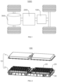
- FIG. 1 is a schematic diagram of a structure of a vehicle 1000 provided in some embodiments of the present disclosure.
- the vehicle 1000 can be a gasoline-powered car, a natural gas car, or a new energy vehicle.
- the new energy vehicles can be pure electric cars, hybrid cars, extended-range cars, etc.
- a battery 100 is provided inside the vehicle 1000, wherein the battery 100 can be arranged at the bottom, front, or rear of the vehicle 1000.
- the battery 100 is configured to provide power for the vehicle 1000.
- the battery 100 can serve as the operational power source for the vehicle 1000.
- the vehicle 1000 also comprises a controller 200 and a motor 300.
- the controller 200 is configured to manage the supply of power from the battery 100 to the motor 300, e.g., for working power requirements for starting, navigating, and driving the vehicle 1000.
- the battery 100 serves not only as the operational power source for the vehicle 1000 but also as the driving power source for the vehicle 1000. It can replace or partially substitute for conventional fuels like gasoline or natural gas to provide driving propulsion for the vehicle 1000.
- FIG. 2 is an exploded view of the structure of a battery 100 provided in some embodiments of the present disclosure.
- the battery 100 comprises a box 10 and multiple battery cells 20, wherein the battery cells 20 are configured to be housed in the box 10.
- the box 10 is configured to provide an assembly space for the battery cell 20, and the box 10 can be of various structures.
- the box 10 can comprise a first box body 11 and a second box body 12, wherein the first box body 11 and the second box body 12 are fitted together.
- the first box body 11 and the second box body 12 collectively define an assembly space for accommodating the battery cell 20.
- the second box body 12 can be a hollow structure open at one end, and the first box body 11 can be a plate-like structure.
- the first box body 11 is capped over an open side of the second box body 12 so that the first box body 11 and the second box body 12 together define an assembly space.
- both the first box body 11 and the second box body 12 can be hollow structures open at one end, and an open side of the first box body 11 is capped over an open side of the second box body 12.
- the box 10 formed by the first box body 11 and the second box body 12 can be of a variety of shapes, e.g., cylindrical, rectangular, etc.
- the multiple battery cells 20 can be connected in series, parallel, or hybrid.
- a hybrid connection refers to having both series and parallel connections among multiple battery cells 20.
- the multiple battery cells 20 can be directly connected in series, parallel, or hybrid, and then the whole comprising the multiple battery cells 20 is housed in the box 10.
- the battery 100 can also be in the form that, the multiple battery cells 20 can be first connected in series, parallel, or hybrid to form battery modules, and then the multiple battery modules can be connected in series, parallel, or hybrid to be formed into a whole, which is accommodated within the box 10.
- the battery 100 can also comprise other structures.
- the battery 100 can also comprise a busbar component, configured for achieving an electrical connection between the multiple battery cells 20.
- the battery 100 can also include a hot management component 30, wherein the hot management component 30 is arranged inside the box 10.
- the hot management component 30 is configured to manage the temperature of the battery cells 20, thus playing a role in cooling and temperature reduction for the battery 100.
- Each battery cell 20 can be a secondary battery or a primary battery. It can also be a lithium-sulfur battery, sodium-ion battery, magnesium-ion battery, or other types, but is not limited to these.
- the battery cell 20 can have various shapes such as cylindrical, flat, rectangular, or other shapes. Exemplarily, in FIG. 2 , the battery cell 20 has a rectangular shape.
- FIG. 3 is a schematic diagram of a structure of a hot management component 30 provided in some embodiments of the present disclosure
- FIG. 4 is a partially enlarged view at A of the hot management component 30 shown in FIG. 3
- FIG. 5 is a schematic diagram of a structure of a hot management component 30 provided in some embodiments of the present disclosure
- FIG. 6 is a partial sectional view of the hot management component 30 provided in some embodiments of the present disclosure.
- the present disclosure provides a hot management component 30, wherein the hot management component 30 comprises a main body part 31 and a shielding member 32.
- the main body part 31 is bent to form multiple connecting regions 311, and the multiple connecting regions 311 are connected sequentially to form an accommodating space 312 for accommodating battery cells 20.
- the connection position of two adjacent connecting regions 311 form a corner region 313, and an interior of the main body part 31 is provided with a medium channel 314 passing through the corner region 313.
- An opening 315 is provided at a position corresponding to the medium channel 314 on a side of the corner region 313 away from the accommodating space 312, and the opening 315 is in communication with the medium channel 314.
- the shielding member 32 is connected to the main body part 31 and seals the opening 315.
- the main body part 31 is a component of the hot management component 30 configured to make contact with the battery cell 20. This enables heat exchange between the main body part 31 and the battery cell 20, thereby achieving the function of the hot management component 30 to manage the temperature of the battery cell 20.
- the main body part 31 is bent to form multiple connecting regions 311, and the multiple connecting regions 311 are connected sequentially to form an accommodating space 312 for accommodating battery cells 20.
- the main body part 31 of the hot management component 30 is a bent structure formed by a bending process of a plate-like structure.
- Each region after bending is a connecting region 311.
- the connecting region 311 is a region configured for heat exchange with the battery cells 20 after making contact.
- the space enclosed by multiple connecting regions 311 is the accommodating space 312 configured for accommodating or arranging the battery cells 20.
- the material and structure of the main body part 31 can be varied.
- the material of the main body part 31 can be aluminum or aluminum alloy, which is pliable and facilitates bending.
- the main body part 31 is bent to form a structure resembling a "U", that is, the main body part 31 is bent twice to form three connecting regions 311.
- the space formed by the three connecting regions 311 of the main body part 31 is the accommodating space 312 configured for accommodating the battery cells 20.
- the main body part 31 can also be bent only once to form two connecting regions 311, such as a structure resembling an "L" or "V". Alternatively, it can be bent three times, four times, or five times to form multiple connecting regions 311. It should be noted that the bending angle of the main body part 31 can be diverse. In FIG.
- the bending angle of the main body part 31 is 90 degrees, meaning that adjacent two connecting regions 311 are perpendicular to each other.
- the bending angle of the main body part 31 can be 30 degrees, 40 degrees, 45 degrees, 60 degrees, or 120 degrees, where adjacent two connecting regions 311 form acute or obtuse angles.
- connection position of adjacent two connecting regions 311 forms a corner region 313, which means that the corner region 313 is the region where the main body part 31 is bent, and the region not bent is the connecting region 311. This ensures that adjacent two connecting regions 311 are connected through a bent region.
- the interior of the main body part 31 is provided with a medium channel 314 passing through the corner region 313.
- the main body part 31 is provided therein with a medium channel 314, and the medium channel 314 passes from one connecting region 311 through a corner region 313 and into another adjacent connecting region 311.
- the location where a projection 316 is formed on the main body part 31 is the location where a medium channel 314 is formed in the interior of the main body part 31.
- two medium channels 314 pass through, thus enabling a loop for the medium channels 314 inside the whole main body part 31.
- the medium channel is configured to accommodate the refrigerant, which means that the refrigerant, when flowing through the medium channel, can undergo heat exchange with the battery cells 20 through the hot management component 30, thereby achieving the function of managing the temperature of the battery cells 20 by the hot management component 30.
- the refrigerant can be a gas, such as air or hydrogen, or it can be a liquid, such as water, saline solution, or liquid nitrogen, and so on.
- an opening 315 corresponding to the position of the medium channel 314 is provided, and the opening 315 is in communication with the medium channel 314.
- the opening 315 is provided on one side of the corner region 313; and the opening 315 is located on the side of the corner region 313 away from the accommodating space 312 and is arranged in the interior of the corner region 313 having the media channel 314. This allows the opening 315 to communicate with the medium channel 314 located in the corner region 313.
- openings 315 are provided at the positions of the two medium channels 314 passing through the corner region 313 so as to facilitate the bending of the main body part 31 to form a bent structure.
- the shielding member 32 is connected to the main body part 31, serving to seal the opening 315.
- the connection position and the connection method between the shielding member 32 and the main body part 31 can be diverse.
- the shielding member 32 can be connected to the side of the main body part 31 away from the accommodating space 312.
- the shielding member 32 can also be arranged inside the opening 315 and connected to the inner sidewall of the opening 315 to seal the opening 315.
- the shielding member 32 can be connected to the main body part 31 using methods such as welding or bonding.
- the shielding member 32 is a structure that extends along the bending direction of the corner region 313.
- the shielding member 32 is an L-shaped structure.
- the connecting regions 311 and corner region 313 together define the accommodating space 312 for accommodating battery cells 20, which allows the main body part 31 of the hot management component 30 to have multiple connecting regions 311 that can be in contact with the battery cells 20.
- it enables effective heat dissipation from the battery cells 20, reducing safety issues of the battery 100 such as thermal spread or thermal runaway.
- the opening 315 is provided on the side of the corner region 313 away from the accommodating space 312 and corresponding to the position where the medium channel 314 is arranged.
- the opening 315 is sealed by a separate shielding member 32 so as to allow the opening 315 to relieve the significant tension generated by the corner region 313 of the main body part 31, which occurs during the bending of the main body part 31 to form the corner region 313 in the production process of the hot management component 30.
- the structure of sealing the opening 315 with the shielding member 32 also ensures the height of the medium channel 314 passing through the corner region 313, thereby enhancing the permeability of the refrigerant in the medium channel 314 to ensure the heat exchange capacity of the hot management component 30.
- multiple connecting regions 311 include a first connecting region 311, a second connecting region 311, and a third connecting region 311, wherein the first connecting region 311 and the third connecting region 311 are arranged opposite to each other, and the second connecting region 311 connects the first connecting region 311 and the third connecting region 311.
- the main body part 31 of the hot management component 30 forms three connecting regions 311, namely the sequentially connected first connecting region, the second connecting region, and the third connecting region.
- the three connecting regions 311 are sequentially connected to form a structure resembling a "U" shape.
- Two of the three connecting regions 311 arranged opposite each other are the first connecting region 311 and the third connecting region 311, i.e., the sequentially connected first connecting region 311, the second connecting region 311, and the third connecting region 311.
- the first connecting region 311 and the third connecting area 311 are arranged opposite to each other so that the main body part 31 of the hot management component 30 is formed into a structure resembling a "U" shape.
- the main body part 31 of the hot management component 30 is bent twice to form a structure resembling a "U", thus providing three connecting regions 311 and two corner regions 313.
- the hot management component 30, using the structure can be in contact with three different surfaces of the battery cell 20 housed in the accommodating space 312, which increases the heat exchange area between the hot management component 30 and the battery cell 20 and effectively enhances the heat management capability for the battery cells 20.
- the adjacent two connecting regions 311 are mutually perpendicular.
- the adjacent two connecting regions 311 are perpendicular to each other, meaning that the bending angle of the main body part 31 is 90 degrees so as to form a 90-degree angle between the adjacent two connecting regions 311.
- the bending angle of the main body part 31 can be 30 degrees, 40 degrees, 45 degrees, 60 degrees, or 120 degrees, where adjacent two connecting regions 311 form acute or obtuse angles.
- the adjacent two connecting regions 311 By arranging the adjacent two connecting regions 311 in a mutually perpendicular structure, it facilitates the mutual fitting of the main body part 31 with different surfaces of the battery cell 20. On one hand, it is convenient to assemble the battery cell 20 into the accommodating space 312 of the main body part 31. On the other hand, it effectively increases the contact area between the hot management component 30 and the battery cell 20.
- the main body part 31 is provided with an outer surface 317, and the opening 315 is provided on the outer surface 317.
- the shielding member 32 fits onto the outer surface 317.
- the main body part 31 is provided with an outer surface 317, and the opening 315 is arranged on the outer surface 317.
- a surface of the side of the main body part 31 provided with the opening 315 is the outer surface 317, which means that a surface of the side of the main body part 31 away from the accommodating space 312 is the outer surface 317.
- the shielding member 32 adheres to the outer surface 317, which means that the shielding member 32 is covered over and connected to a portion of the outer surface 317 of the main body part 31 to seal the opening 315.
- the opening 315 is provided on the outer surface 317 of the main body part 31, meaning that the side of the main body part 31 away from the accommodating space 312 is the outer surface 317 of the main body part 31. This allows the opening 315 to be provided on the outer surface 317 of the main body part 31.
- the hot management component 30 With the structure is conducive to enhancing the sealing effect of the shielding member 32 on the opening 315. Additionally, it facilitates the connection of the shielding member 32 to the main body part 31, thus reducing processing difficulty. Moreover, it effectively increases the connecting area between the shielding member 32 and the main body part 31, thereby promoting the stability and reliability of the connection between the shielding member 32 and the main body part 31.
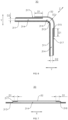
- FIG. 7 is a partial sectional view at a corner region 313 of the hot management component 30 provided in some embodiments of the present disclosure.
- a width of a portion of the shielding member 32 that extends beyond the edge of the opening 315 is denoted as D 1 , which satisfies 6mm ⁇ D 1 ⁇ 15mm.
- a width of a portion of the shielding member 32 that extends beyond the edge of the opening 315 is denoted as D 1 . That is to say, after the shielding member 32 adheres to the outer surface 317 of the main body part 31 and covers the entire opening 315, the overlap size between the shielding member 32 and the outer surface 317 of the main body part 31 is denoted as D 1 .
- the range of D 1 is between 6mm and 15mm. In other words, the overlap dimensions of the edges of the periphery of the shielding member 32 and the outer surface 317 of the main body part 31 are all in the range of 6 mm to 15 mm.
- the width D 1 of a portion of the shielding member 32 that extends beyond the edge of the opening 315 can be 6mm, 6.5mm, 7mm, 8mm, 10mm, 12mm or 15mm, etc.
- the width of the portion of the shielding member 32 that extends beyond the edge of the opening 315 is between 6mm and 15mm.
- the overlap dimension between both ends of the shielding member 32 and the outer surface 317 of the main body part 31 is between 6mm and 15mm.
- the width of the portion of the shielding member 32 that extends beyond the edge of the opening 315 is between 6mm and 15mm.
- the overlap dimension between both ends of the shielding member 32 and the outer surface 317 of the main body part 31 is between 6mm and 15mm.
- this structure By setting the width of the portion of the shielding member 32 that extends beyond the edge of the opening 315 at 6 mm to 15 mm, this structure, on the one hand, can alleviate the phenomenon of poor sealing effectiveness of the opening 315 by the shielding member 32 due to a too-small overlap dimension, thereby reducing the risk of refrigerant leakage; on the other hand, it can reduce the redundancy of the shielding member 32 due to a too-large overlap dimension, thereby contributing to the saving of the material of the shielding member 32 so as to reduce the manufacturing cost of the hot management component 30.
- a size of a portion of the medium channel 314 located within the connecting region 311 is denoted as D 2 .
- a portion of the medium channel 314 located within the corner region 313 is provided with a first inner sidewall and a second inner sidewall facing each other.
- the opening 315 passes through the first inner sidewall, and a distance between the shielding member 32 and the second inner sidewall is denoted as D 3 , satisfying D 3 ⁇ D 2 .
- the size of a portion of the medium channel 314 located within the connecting region 311 is denoted as D 2 , which means that in the thickness direction Y of the connecting region, the height dimension of the medium channel 314 located within the connecting region 311 is D 2 .
- a portion of the medium channel 314 located within the corner region 313 is provided with a first inner sidewall and a second inner sidewall facing each other.
- the opening 315 passes through the first inner sidewall, and a distance between the shielding member 32 and the second inner sidewall is denoted as D 3 . That is, in the thickness direction Z of the corner region, the medium channel 314 located within the corner region 313 is provided with two inner sidewalls arranged opposite to each other, and the distance between one of the inner sidewalls away from the shielding member 32 and the shielding member 32 is D 3 .
- the height of the cavity is jointly defined by the shielding member 32 and the medium channel 314 inside the corner region 313 is D 3 .
- the hot management component 30 By setting the size of the medium channel 314 in the corner region 313 to be greater than the size of the medium channel 314 in the connecting region 311, the hot management component 30 using this structure ensures the permeability of the refrigerant in the medium channel 314 located within the corner region 313. This helps to reduce the risk of blockage when the refrigerant flows through the medium channel 314 located within the corner region 313, thus ensuring the normal operation of the hot management component 30. It, in turn, enables a balanced heat exchange capacity among multiple connecting regions 311.
- D 2 can be 2mm, 2.1mm, 2.2mm, 2.5mm, 2.8mm, or 3mm, and the like.
- D 3 can be 2mm, 2.1mm, 2.2mm, 2.5mm, 2.8mm, 3mm, or 4mm, and the like.
- the embodiments of the present disclosure further provide a battery 100, wherein the battery 100 comprises a box 10, a battery cell 20, and the hot management component 30 according to any one of the solutions above.
- the battery cell 20 is housed in the box 10.
- the hot management component 30 is arranged in the box 10, the battery cell 20 is arranged in the main body part 31 of the accommodating space 312, and the hot management component 30 is configured to manage the temperature of the battery cell 20.
- the embodiments of the present disclosure provide an electric device, wherein the electric device comprises a battery 100 of any of the above solutions, and the battery 100 is configured to provide electrical energy to the electric device.
- the electric device can be any of the above-mentioned devices or systems that apply the battery 100.
- the present disclosure provides a hot management component 30, wherein the hot management component 30 comprises a main body part 31 and a shielding member 32.
- the main body part 31 is bent to form three connecting regions 311, and the three connecting regions 311 are connected sequentially to form an accommodating space 312 for accommodating battery cells 20.
- the connecting position of adjacent two connecting regions 311 forms a corner region 313, and the adjacent two connecting regions 311 are mutually perpendicular.
- An interior of the main body part 31 is provided with a medium channel 314 passing through the corner region 313.
- An opening 315 is provided at a position corresponding to the medium channel 314 on a side of the corner region 313 away from the accommodating space 312, and the opening 315 is in communication with the medium channel 314.
- the shielding member 32 is connected to the main body part 31, the main body part 31 is provided with an outer surface 317, and the opening 315 is provided on the outer surface 317.
- the shielding member 32 fits onto the outer surface 317 and seals the opening 315.
- a width of a portion of the shielding member 32 that extends beyond the edge of the opening 315 is denoted as D 1 , which satisfies 6mm ⁇ D 1 ⁇ 15mm.
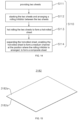
- FIG. 8 is a flowchart of a manufacturing method of the hot management component 30 provided by the embodiment of the present disclosure, wherein the manufacturing method comprises
- the shielding member 32 blocks the opening 315, thus reducing the risk of refrigerant leakage in the medium channel 314.
- the connection between the shielding member 32 and the main body part 31 can be various, such as welding or bonding.
- the main body part 31 with multiple connecting regions 311 is first processed by bending, and on one side of the corner region 313 formed at the connection position of adjacent two connecting regions 311, an opening 315 in communication with the medium channel 314 is formed. Subsequently, the opening 315 is sealed by the shielding member 32 to form a hot management component 30 for regulating the temperature of battery cells 20.
- the hot management component 30 manufactured using the manufacturing method ensures the height of the medium channel 314 passing through the corner region 313. This is advantageous in enhancing the permeability of the refrigerant in the medium channel 314 and ensuring the heat exchange capacity of the hot management component 30.
- FIG. 10 is a flowchart of step S100 of the manufacturing method of the hot management component 30 provided by the embodiment of the present disclosure.
- the step of "S100: providing the main body part 31" comprises the following steps.
- FIG. 11 is a structural schematic diagram of a composite sheet 318 provided in some embodiments of the present disclosure.
- FIG. 12 is a structural schematic diagram of the composite sheet 318 provided in some embodiments of the present disclosure after step S120; and FIG. 13 is a top view of the composite sheet 318 provided in some embodiments of the present disclosure after step S120.
- a medium channel 314 for the flow of the refrigerant is formed inside the composite sheet 318, wherein the position of the projection 316 on the composite sheet 318 is the location of the medium channel 314.
- the composite sheet 318 is divided into multiple regions, the composite sheet 318 is provided with the region to be bent 3181 for bending, and the region of the composite sheet 318 that does not need to be bent is the connecting region 311 of the main body part 31.
- Each of the two adjacent connecting regions 311 is connected by one region to be bent 3181.
- the medium channel 314 formed inside the composite sheet 318 passes from one connecting region 311 through the region to be bent 3181 and into another adjacent connecting region 311.
- the corner region 313 of the main body part 31 is formed when the region to be bent 3181 is bent.
- the composite sheet 318 is provided therein with a medium channel 314, and the manufacturing method of the composite sheet 318 can be various, such as forming the composite sheet 318 provided therein with the medium channel 314 through processes like stamping or casting. It can also be formed by the expansion process to form the medium channel 314 inside the composite sheet 318.
- one side of the region to be bent 3181 of the composite sheet 318 is provided with an opening 315.
- the opening 315 is in communication with a portion of the medium channel 314 located inside the region to be bent 3181, thus facilitating subsequent processing to bend the composite sheet 318 and form the main body part 31.
- the method of providing the opening 315 on the composite sheet 318 can be various.
- the opening 315 can be formed in the region to be bent 3181 of the composite sheet 318 by laser cutting or mechanical tool cutting.
- the opening 315 is first provided on one side of the composite sheet 318 at a position where the medium channel 314 is arranged. Subsequently, the composite sheet 318 is bent towards the side away from the opening 315 to form the structure so as to bend the composite sheet 318 to form multiple connecting regions 311 and corner regions 313 and enable the opening 315 to be arranged on the side of the corner region 313 away from the accommodating space 312. Therefore, the main body part 31 of the hot management component 30 is formed.
- the main body part 31 manufactured using the manufacturing method, through the opening 315 can effectively alleviate the significant tension generated on the side of the corner region 313 away from the accommodating space 312 during the bending process, thus reducing the risk of breakage or collapse in the corner region 313. On one hand, it ensures the permeability of the medium channel 314 located within the corner region 313. On the other hand, it ensures the production quality and yield of the hot management component 30.
- FIG. 14 is a flowchart of step S110 of the manufacturing method of the hot management component 30 provided by the embodiment of the present disclosure.
- the step of S110: providing a composite sheet 318 includes
- the material of the two sheets 3182a provided in step S111 can be a material that is easily bendable, such as aluminum or aluminum alloy.
- step S112 before hot-rolling the two sheets 3182a, it is necessary to coat a rolling inhibitor between the two sheets 3182a.
- a rolling inhibitor between the two sheets 3182a.
- the material of the rolling inhibitor can be various, such as graphite or boron nitride emulsion.
- the shape of the coated area of the rolling inhibitor can also be various. In the actual manufacturing process, the rolling inhibitor can be coated between the two sheets 3182a with different shapes according to the actual requirements of the medium channel 314. The embodiments of the present disclosure do not limit the specific shape.
- step S113 the two sheets 3182a are hot-rolled to form a hot-rolled sheet 3182. Since a portion of the region between the two sheets 3182a is coated with a rolling inhibitor, the region between the two sheets 3182a coated with the rolling inhibitor will not be hot rolled into one piece during the hot rolling of the two sheets 3182a. Instead, the region between the two sheets 3182a that is not coated with the rolling inhibitor will be hot-rolled into one piece, thereby facilitating the subsequent formation of the medium channel 314 after blowing the hot-rolled sheet 3182.
- step S114 during the expansion process of the hot-rolled plate 3182, the region where the two sheets 3182a are coated with the rolling inhibitor deforms and arches, forming the projection 316 on the composite sheet 318.
- This enables the formation of the medium channels 314 inside the hot-rolled sheet 3182 at a location corresponding to the projection 316, thus forming the composite sheet 318 (as shown in FIG. 11 ).
- Specific embodiments of the expansion process can be found in the related art and will not be repeated here.
- the composite sheet 318 is formed by hot rolling two sheets 3182a and then expanding, thus forming a medium channel 314 inside the composite sheet 318 for the flow of refrigerant.
- the composite sheet 318 using the manufacturing method is less difficult to manufacture and has higher production efficiency, thus facilitating the mass production of hot management components 30.
Landscapes
- Engineering & Computer Science (AREA)
- Chemical & Material Sciences (AREA)
- Chemical Kinetics & Catalysis (AREA)
- Electrochemistry (AREA)
- General Chemical & Material Sciences (AREA)
- Manufacturing & Machinery (AREA)
- Mechanical Engineering (AREA)
- Physics & Mathematics (AREA)
- Fluid Mechanics (AREA)
- Secondary Cells (AREA)
Abstract
Description
- The present disclosure relates to the technical field of batteries, in particular to a hot management component and manufacturing method thereof, a battery, and an electric device.
- In recent years, new energy vehicles have experienced a leapfrog development. In the field of electric vehicles, power batteries serve as the energy source for electric vehicles and play an irreplaceable important role. The battery consists of a box and multiple battery cells accommodated within the box. The battery, as the core component of new energy vehicles, has high requirements in terms of both safety and service life. However, during the continuous charging and discharging process, the battery cells inside the battery generate a large amount of heat, leading to a rapid increase in the internal temperature of the battery. This significantly affects the performance and lifespan of the battery, and may even pose significant safety hazards during use, which is not conducive to consumer use safety.
- The embodiments of the present disclosure provide a hot management component and manufacturing method thereof, a battery and an electric device, which are capable of effectively enhancing the safety and lifespan of the battery in use.
- In the first aspect, the embodiments of the present disclosure provide a hot management component comprising a main body part and a shielding member. The main body part is bent to form multiple connecting regions, and the multiple connecting regions are connected sequentially to form an accommodating space for accommodating battery cells. The connection position of two adjacent connecting regions forms a corner region, and an interior of the main body part is provided with a medium channel passing through the corner region. An Opening is provided at a position corresponding to the medium channel on a side of the corner region away from the accommodating space, and the opening is in communication with the medium channel. The shielding member is connected to the main body part and seals the opening.
- In the above technical solution, by bending the main body part of the hot management component to form multiple connecting regions and forming the corner region at the connection positions of two adjacent connecting regions, the connecting regions and corner region together define the accommodating space for accommodating battery cells, which allows the main body part of the hot management component to have multiple connecting regions that can be in contact with the battery cells. This effectively increases the heat exchange area between the hot management component and the battery cells so as to improve the heat exchange efficiency of the hot management component. On one hand, it enables effective heat dissipation from the battery cells, reducing safety issues of the battery such as thermal spread or thermal runaway. On the other hand, when multiple battery cells are arranged in the accommodating space of the hot management component, it can reduce the temperature difference between the multiple battery cells, thereby reducing the impact on the lifespan of the battery cells. This, in turn, contributes to enhancing the safety and lifespan of the battery. Additionally, on the side of the corner region away from the accommodating space and corresponding to the position where the medium channel is arranged, the opening is provided. The opening is sealed by a separate shielding member so as to allow the opening to relieve the significant tension generated by the corner region of the main body part, which occurs during the bending of the main body part to form the corner region in the production process of the hot management component. This helps to mitigate the risk of the corner region of the main body breaking or collapsing, thus ensuring the production quality and yield of the hot management component. The structure of sealing the opening with the shielding member also ensures the height of the medium channel passing through the corner region, thereby enhancing the permeability of the refrigerant in the medium channel to ensure the heat exchange capacity of the hot management component.
- In some embodiments, multiple connecting regions include a first connecting region, a second connecting region, and a third connecting region, wherein the first connecting region and the third connecting region are arranged opposite to each other, and the second connecting region connects the first connecting region and the third connecting region.
- In the above technical solution, the main body part of the hot management component forms three connecting regions, namely the sequentially connected first connecting region, the second connecting region, and the third connecting region. The first connecting region and the third connecting region are arranged opposite to each other so that the main body part of the hot management component is formed into a structure resembling a "U" shape. The hot management component, using the structure, can be in contact with three different surfaces of the battery cell housed in the accommodating space, which increases the heat exchange area between the hot management component and the battery cell and effectively enhances the heat management capability for the battery cells.
- In some embodiments, the adjacent two connecting regions are mutually perpendicular.
- In the above technical solution, by arranging the adjacent two connecting regions in a mutually perpendicular structure, it facilitates the mutual fitting of the main body part with different surfaces of the battery cell. On one hand, it is convenient to assemble the battery cell into the accommodating space of the main body part. On the other hand, it effectively increases the contact area between the hot management component and the battery cell.
- In some embodiments, the main body part is provided with an outer surface, and the opening is provided on the outer surface. The shielding member fits onto the outer surface.
- In the above technical solution, the opening is provided on the outer surface of the main body part, meaning that the side of the main body part away from the accommodating space is the outer surface of the main body part. This allows the opening to be provided on the outer surface of the main body part. By fitting the shielding member onto the outer surface of the main body part, the hot management component with the structure is conducive to enhancing the sealing effect of the shielding member on the opening. Additionally, it facilitates the connection of the shielding member to the main body part, thus reducing processing difficulty. Moreover, it effectively increases the connecting area between the shielding member and the main body part, thereby promoting the stability and reliability of the connection between the shielding member and the main body part.
- In some embodiments, a width of a portion of the shielding member that extends beyond the edge of the opening is denoted as D1, which satisfies 6mm ≤ D1 ≤ 15mm.
- In the above technical solution, by setting the width of the portion of the shielding member that extends beyond the edge of the opening to be within the range of 6mm to 15mm, it means that the overlap dimension between the shielding member and the outer surface of the main body part is in the range of 6mm to 15mm. This structure, on the one hand, can alleviate the phenomenon of poor sealing effectiveness of the opening by the shielding member due to a too-small overlap dimension, thereby reducing the risk of refrigerant leakage; on the other hand, it can reduce the redundancy of the shielding member due to a too-large overlap dimension, thereby contributing to the saving of the material of the shielding member so as to reduce the manufacturing cost of the hot management component.
- In some embodiments, along a thickness direction of the connecting region, a size of a portion of the medium channel located within the connecting region is denoted as D2. Along a thickness direction of the corner region, a portion of the medium channel located within the corner region is provided with a first inner sidewall and a second inner sidewall facing each other. The opening passes through the first inner sidewall, and a distance between the shielding member and the second inner sidewall is denoted as D3, satisfying D3 ≥ D2.
- In the above technical solution, by setting the size of the medium channel in the corner region to be greater than the size of the medium channel in the connecting region, the hot management component using this structure ensures the permeability of the refrigerant in the medium channel located within the corner region. This helps to reduce the risk of blockage when the refrigerant flows through the medium channel located within the corner region, thus ensuring the normal operation of the hot management component. It, in turn, enables a balanced heat exchange capacity among multiple connecting regions.
- In some embodiments, 2mm≤D2≤3mm.
- In the above technical solution, by setting the size of the medium channel in the connecting region to be within the range of 2mm to 3mm, it alleviates the problem of poor permeability of the refrigerant in the medium channel due to a too-small size. On the other hand, it reduces the phenomenon of the main body part of the hot management component occupying too much space due to a too-large size, thus ensuring the energy density of the battery provided with the hot management component.
- In some embodiments, 2mm≤D3≤4mm.
- In the above technical solution, by setting the size of the medium channel in the corner region to be within the range of 2mm to 4mm, it alleviates the problem of poor permeability of the refrigerant in the medium channel due to a too-small size. On the other hand, it helps to reduce the difficulty of manufacturing the main body part of the hot management component at the location of the corner region due to a too-large size.
- In the second aspect, the embodiments of the present disclosure further provide a battery, comprising a box, a battery cell, and the aforementioned hot management component. The battery cell is housed in the box. The hot management component is arranged in the box, the battery cell is arranged in the accommodating space, and the hot management component is configured to manage the temperature of the battery cells.
- In the third aspect, the embodiments of the present disclosure further provide an electric device comprising the battery as described above, wherein the battery is configured to provide electrical energy.
- In the fourth aspect, the embodiments of the present disclosure provide a manufacturing method of the hot management component, comprising providing a main body part, wherein the main body part is bent to form multiple connecting regions, and the multiple connecting regions are connected sequentially to form an accommodating space for accommodating battery cells; the connection position of two adjacent connecting regions form a corner region, and an interior of the main body part is provided with a medium channel passing through the corner region; an opening is provided at a position corresponding to the medium channel on a side of the corner region away from the accommodating space, and the opening is in communication with the medium channel; and providing a shielding member, wherein the shielding member is connected to the main body part so as to seal the openings.
- In the above technical solution, the main body part with multiple connecting regions is first processed by bending, and on one side of the corner region formed at the connection position of adjacent two connecting regions, an opening in communication with the medium channel is formed. Subsequently, the opening is sealed by the shielding member to form a hot management component for regulating the temperature of battery cells. The hot management component manufactured using the manufacturing method ensures the height of the medium channel passing through the corner region. This is advantageous in enhancing the permeability of the refrigerant in the medium channel and ensuring the heat exchange capacity of the hot management component.
- In some embodiments, providing the main body part comprises providing a composite sheet, where the interior of the composite sheet forms a medium channel; arranging an opening on one side of the composite sheet in communication with the medium channel; and bending the composite sheet to form the main body part.
- In the above technical solution, the opening is first provided on one side of the composite sheet at a position where the medium channel is arranged. Subsequently, the composite sheet is bent towards the side away from the opening to form the structure so as to bend the composite sheet to form multiple connecting regions and corner regions and enable the opening to be arranged on the side of the corner region away from the accommodating space. Therefore, the main body part of the hot management component is formed. The main body part manufactured using the manufacturing method, through the opening, can effectively alleviate the significant tension generated on the side of the corner region away from the accommodating space during the bending process, thus reducing the risk of breakage or collapse in the corner region. On one hand, it ensures the permeability of the medium channel located within the corner region. On the other hand, it ensures the production quality and yield of the hot management component.
- In some embodiments, providing a composite sheet comprises providing two sheets; stacking the two sheets and arranging a rolling inhibitor between the two sheets; hot rolling the two sheets to form a hot-rolled sheet; and expanding (blowing up) the hot-rolled sheet, so as to enable the hot-rolled sheet to form a medium channel at the position where the rolling inhibitor is arranged, to form a composite sheet.
- In the above technical solution, the composite sheet is formed by hot rolling two sheets and then expanding, thus forming a medium channel inside the composite sheet for the flow of refrigerant. The composite sheet using the manufacturing method is less difficult to manufacture and has higher production efficiency, thus facilitating the mass production of hot management components.
- To more clearly illustrate the technical solutions of the embodiments of the present disclosure, the following will briefly introduce the drawings used in the embodiments. It should be understood that the following drawings only show some embodiments of the present disclosure, and therefore they should not be regarded as a limitation on the scope. Those ordinary skilled in the art can also obtain other related drawings based on these drawings without inventive effort.
-
FIG. 1 is a schematic diagram of a structure of a vehicle provided in some embodiments of the present disclosure; -
FIG. 2 is an exploded view of the structure of a battery provided in some embodiments of the present disclosure; -
FIG. 3 is a schematic diagram of a structure of a hot management component provided in some embodiments of the present disclosure; -
FIG. 4 is a partially enlarged view at A of the hot management component shown inFIG. 3 ; -
FIG. 5 is an exploded diagram of a structure of a hot management component provided in some embodiments of the present disclosure; -
FIG. 6 is a partial sectional view of the hot management component provided in some embodiments of the present disclosure; -
FIG. 7 is a partial sectional view at a corner region of the hot management component provided in some embodiments of the present disclosure; -
FIG. 8 is a flowchart of a manufacturing method of the hot management component provided by the embodiment of the present disclosure; -
FIG. 9 is a schematic diagram of a structure of a main body part of the hot management component provided in some embodiments of the present disclosure; -
FIG. 10 is a flowchart of step S100 of the manufacturing method of the hot management component provided by the embodiment of the present disclosure; -
FIG. 11 is a structural schematic diagram of a composite sheet provided in some embodiments of the present disclosure; -
FIG. 12 is a structural schematic diagram of the composite sheet provided in some embodiments of the present disclosure after step S120; -
FIG. 13 is a top view of the composite sheet provided in some embodiments of the present disclosure after step S120; -
FIG. 14 is a flowchart of step S110 of the manufacturing method of the hot management component provided by the embodiment of the present disclosure; and -
FIG. 15 is a structural schematic diagram of a hot-rolled sheet provided in some embodiments of the present disclosure. - Reference numerals: 1000- vehicle; 100- battery; 10- box; 11- first box body; 12- second box body; 20- battery cell; 30- hot management component; 31- main body part; 311- connecting region; 312- accommodating space; 313-corner region; 314- medium channel; 315- opening; 316- projection; 317-outer surface; 318- composite sheet; 3181- region to be bent; 3182- hot-rolled sheet; 3182a- sheet; 32- shielding member; 200- controller; 300- motor; X-extension direction of the corner region; Y- thickness direction of the connecting region; Z- thickness direction of the corner region.
- In order to make the objective, technical solution, and advantages of the embodiments of the present disclosure clearer, the following will provide a clear and complete description of the technical solution in the embodiments of the present disclosure, in conjunction with the drawings in the embodiments of the present disclosure. Obviously, the described embodiments are only a part of the embodiments of the present disclosure, rather than all embodiments. Based on the embodiments in the present disclosure, all other embodiments obtained by those of ordinary skill in the art without making inventive efforts are within the scope of protection of the present disclosure.
- Unless otherwise defined, all technical and scientific terms used herein have the same meaning as understood by those skilled in the art of the relevant technical field. The terms used in the summary of the present disclosure are used for the purpose of describing specific embodiments and are not intended to limit the present disclosure. The terms "comprise" and "provide" and their variations, as well as any other variations, are intended to cover non-exclusive inclusion in the summary and the claims of the present disclosure, as well as in the drawings. The terms "first", "second", etc., used in the summary and claims of the present disclosure, or in the above drawings, are used to distinguish between different objects and are not intended to describe a specific sequence or hierarchy.
- The term "embodiment" used in the present disclosure means that specific features, structures, or characteristics described in conjunction with the embodiment can be included in at least one embodiment of the present disclosure. The use of this phrase in various parts of the summary does not necessarily refer to the same embodiment, nor does it imply that these embodiments are mutually exclusive or independent of each other.
- In the description of the present disclosure, it should be noted that, unless otherwise clearly stipulated and limited, the terms "provide", "interconnect", "connect" and "attach" should be understood in a broad sense, for example, it can be a fixed connection, a detachable connection, or an integral connection, and it can be a direct connection, an indirect connection through an intermediary, or an internal communication between two components. Those of ordinary skill in the art can understand the meanings of the above terms in the present disclosure according to specific situations.
- In the present disclosure, the term "and/or" is used as a way to describe the relationship between associated objects, indicating that there can be three possible relationships. For example, "A and/or B" can represent: the presence of A alone, the presence of both A and B, or the presence of B alone. Additionally, the character "/" in the present disclosure generally represents an "or" relationship between the preceding and following associated objects.
- In the embodiments of the present disclosure, identical reference numerals indicate the same components. For the sake of conciseness, detailed explanations of the same components are omitted in different embodiments. It should be understood that the dimensions such as thickness, length, and width of various components in the embodiments of the present disclosure as shown in the drawings, as well as the overall dimensions such as thickness, length, and width of the integrated device, are provided as illustrative examples and should not be construed to limit the scope of the present disclosure.
- In the present disclosure, the term "multiple" refers to two or more (including two).
- In the present disclosure, the battery cell can comprise various types of batteries such as lithium-ion secondary batteries, lithium-ion primary batteries, lithium-sulfur batteries, sodium-ion batteries, magnesium-ion batteries, etc. The embodiments of the present disclosure are not limited to any specific type of battery. The battery cell can have various shapes such as cylindrical, flat, rectangular, or other shapes. The embodiments of the embodiments of the present disclosure do not impose limitations on this aspect either. The battery cells are generally categorized into three packaging types: cylindrical battery cells, prismatic battery cells, and pouch battery cells. The embodiments of the embodiments of the present disclosure do not impose limitations in this regard either.
- The batteries mentioned in the embodiments of the present disclosure refer to a single physical module that comprises one or multiple battery cells to provide higher voltage and capacity. For example, the batteries mentioned in the present disclosure can comprise battery modules or battery packs, and so on. A battery generally comprises a box for encapsulating one or multiple battery cells or multiple battery modules. The box helps to prevent liquids or other foreign substances from affecting the charging or discharging of the battery cells.
- In recent years, new energy vehicles have experienced a leapfrog development. In the field of electric vehicles, power batteries serve as the energy source for electric vehicles and play an irreplaceable important role. The battery consists of a box and multiple battery cells accommodated within the box. The battery, as the core component of new energy vehicles, has high requirements in terms of both safety and cycle service life.
- The inventors have found that, in conventional power batteries, to ensure that the battery obtains sufficient power, multiple battery cells within the box of the battery are typically arranged in a stacked configuration. However, during the continuous charging and discharging process, the battery cells inside the battery generate a large amount of heat, leading to a rapid increase in the internal temperature of the battery. The stacked arrangement of multiple battery cells exacerbates this phenomenon. This significantly affects the performance and lifespan of the battery, and may even pose significant safety hazards during use, which is not conducive to consumer safety. Therefore, in existing technologies, it is common to arrange a water-cooling plate inside the box of the battery. The water-cooling plate is arranged on one side of multiple battery cells, and a channel for the flow of a cooling medium is formed in the interior of the water-cooling plate. This allows the water-cooling plate to play a role in cooling and temperature reduction for the battery cells. However, the structure of the water-cooling plate has a relatively small heat exchange area with the battery cells inside the box of the battery, leading to lower heat exchange efficiency. This not only prevents effective heat dissipation from the battery cells, leading to potential safety issues such as thermal spread or thermal runaway but also results in temperature differences between multiple battery cells, thus adversely affecting the lifespan of the battery cells. Consequently, it hinders the improvement of both the safety and lifespan of the battery.
- Based on the above considerations and to address the issues of lower safety and shorter lifespan in existing batteries, the inventors conducted in-depth research and designed a hot management component. The hot management component comprises a main body part and a shielding member. The main body part is bent to form multiple connecting regions, and the multiple connecting regions are connected sequentially to form an accommodating space for accommodating battery cells. The connection position of two adjacent connecting regions forms a corner region, and an interior of the main body part is provided with a medium channel passing through the corner region. An Opening is provided at a position corresponding to the medium channel on a side of the corner region away from the accommodating space, and the opening is in communication with the medium channel. The shielding member is connected to the main body part and seals the opening.
- In the hot management component of the structure, by bending the main body part of the hot management component to form multiple connecting regions and forming the corner region at the connection positions of two adjacent connecting regions, the connecting regions and corner region together define the accommodating space for accommodating battery cells, which allows the main body part of the hot management component to have multiple connecting regions that can be in contact with the battery cells. This effectively increases the heat exchange area between the hot management component and the battery cells so as to improve the heat exchange efficiency of the hot management component. On one hand, it enables effective heat dissipation from the battery cells, reducing safety issues of the battery such as thermal spread or thermal runaway. On the other hand, when multiple battery cells are arranged in the accommodating space of the hot management component, it can reduce the temperature difference between the multiple battery cells, thereby reducing the impact on the lifespan of the battery cells. This, in turn, contributes to enhancing the safety and lifespan of the battery.
- Additionally, on the side of the corner region away from the accommodating space and corresponding to the position where the medium channel is arranged, the opening is provided. The opening is sealed by a separate shielding member so as to allow the opening to relieve the significant tension generated by the corner region of the main body part, which occurs during the bending of the main body part to form the corner region in the production process of the hot management component. This helps to mitigate the risk of the corner region of the main body breaking or collapsing, thus ensuring the production quality and yield of the hot management component. The structure of sealing the opening with the shielding member also ensures the height of the medium channel passing through the corner region, thereby enhancing the permeability of the refrigerant in the medium channel to ensure the heat exchange capacity of the hot management component.
- The hot management component disclosed in the embodiments of the present disclosure can be used in various electric devices, comprising but not limited to vehicles, ships, or aircraft. The power system of the electric device can be formed using the hot management component and battery disclosed in the present disclosure. This helps to enhance the heat exchange capacity of the hot management component, thus improving the safety and lifespan of the battery.
- The embodiments of the present disclosure provide an electric device that uses batteries as a power source. The electric device can comprise but is not limited to, mobile phones, tablets, laptops, electric toys, power tools, electric bicycles, electric cars, boats, spacecraft, and more. The electric toys can include stationary or mobile electric toys, for example, video game consoles, electric car toys, electric boat toys, and electric airplane toys. The spacecraft can include aircraft, rockets, space shuttles, and spacecraft, among others.
- For ease of explanation, the following embodiment will be described using one embodiment of the present disclosure where the electric device is a vehicle as an example.
- Referring to
FIG. 1, FIG. 1 is a schematic diagram of a structure of avehicle 1000 provided in some embodiments of the present disclosure. Thevehicle 1000 can be a gasoline-powered car, a natural gas car, or a new energy vehicle. The new energy vehicles can be pure electric cars, hybrid cars, extended-range cars, etc. Abattery 100 is provided inside thevehicle 1000, wherein thebattery 100 can be arranged at the bottom, front, or rear of thevehicle 1000. Thebattery 100 is configured to provide power for thevehicle 1000. For instance, thebattery 100 can serve as the operational power source for thevehicle 1000. Additionally, thevehicle 1000 also comprises acontroller 200 and amotor 300. Thecontroller 200 is configured to manage the supply of power from thebattery 100 to themotor 300, e.g., for working power requirements for starting, navigating, and driving thevehicle 1000. - In some embodiments of the present disclosure, the
battery 100 serves not only as the operational power source for thevehicle 1000 but also as the driving power source for thevehicle 1000. It can replace or partially substitute for conventional fuels like gasoline or natural gas to provide driving propulsion for thevehicle 1000. - Referring to
FIG. 2, FIG. 2 is an exploded view of the structure of abattery 100 provided in some embodiments of the present disclosure. Thebattery 100 comprises a box 10 andmultiple battery cells 20, wherein thebattery cells 20 are configured to be housed in the box 10. The box 10 is configured to provide an assembly space for thebattery cell 20, and the box 10 can be of various structures. In some embodiments, the box 10 can comprise a first box body 11 and asecond box body 12, wherein the first box body 11 and thesecond box body 12 are fitted together. The first box body 11 and thesecond box body 12 collectively define an assembly space for accommodating thebattery cell 20. Thesecond box body 12 can be a hollow structure open at one end, and the first box body 11 can be a plate-like structure. The first box body 11 is capped over an open side of thesecond box body 12 so that the first box body 11 and thesecond box body 12 together define an assembly space. Alternatively, both the first box body 11 and thesecond box body 12 can be hollow structures open at one end, and an open side of the first box body 11 is capped over an open side of thesecond box body 12. Of course, the box 10 formed by the first box body 11 and thesecond box body 12 can be of a variety of shapes, e.g., cylindrical, rectangular, etc. - In the
battery module 100, themultiple battery cells 20 can be connected in series, parallel, or hybrid. A hybrid connection refers to having both series and parallel connections amongmultiple battery cells 20. Themultiple battery cells 20 can be directly connected in series, parallel, or hybrid, and then the whole comprising themultiple battery cells 20 is housed in the box 10. Of course, thebattery 100 can also be in the form that, themultiple battery cells 20 can be first connected in series, parallel, or hybrid to form battery modules, and then the multiple battery modules can be connected in series, parallel, or hybrid to be formed into a whole, which is accommodated within the box 10. Thebattery 100 can also comprise other structures. For example, thebattery 100 can also comprise a busbar component, configured for achieving an electrical connection between themultiple battery cells 20. - In some embodiments of the present disclosure, with reference to
FIG. 2 , thebattery 100 can also include ahot management component 30, wherein thehot management component 30 is arranged inside the box 10. Thehot management component 30 is configured to manage the temperature of thebattery cells 20, thus playing a role in cooling and temperature reduction for thebattery 100. - Each
battery cell 20 can be a secondary battery or a primary battery. It can also be a lithium-sulfur battery, sodium-ion battery, magnesium-ion battery, or other types, but is not limited to these. Thebattery cell 20 can have various shapes such as cylindrical, flat, rectangular, or other shapes. Exemplarily, inFIG. 2 , thebattery cell 20 has a rectangular shape. - According to some embodiments of the present disclosure, with reference to
FIG. 3 to FIG. 6 ,FIG. 3 is a schematic diagram of a structure of ahot management component 30 provided in some embodiments of the present disclosure;FIG. 4 is a partially enlarged view at A of thehot management component 30 shown inFIG. 3 ;FIG. 5 is a schematic diagram of a structure of ahot management component 30 provided in some embodiments of the present disclosure; andFIG. 6 is a partial sectional view of thehot management component 30 provided in some embodiments of the present disclosure. The present disclosure provides ahot management component 30, wherein thehot management component 30 comprises amain body part 31 and a shieldingmember 32. Themain body part 31 is bent to form multiple connectingregions 311, and the multiple connectingregions 311 are connected sequentially to form anaccommodating space 312 for accommodatingbattery cells 20. The connection position of two adjacent connectingregions 311 form acorner region 313, and an interior of themain body part 31 is provided with amedium channel 314 passing through thecorner region 313. Anopening 315 is provided at a position corresponding to themedium channel 314 on a side of thecorner region 313 away from theaccommodating space 312, and theopening 315 is in communication with themedium channel 314. The shieldingmember 32 is connected to themain body part 31 and seals theopening 315. - The
main body part 31 is a component of thehot management component 30 configured to make contact with thebattery cell 20. This enables heat exchange between themain body part 31 and thebattery cell 20, thereby achieving the function of thehot management component 30 to manage the temperature of thebattery cell 20. - The
main body part 31 is bent to form multiple connectingregions 311, and the multiple connectingregions 311 are connected sequentially to form anaccommodating space 312 for accommodatingbattery cells 20. In other words, themain body part 31 of thehot management component 30 is a bent structure formed by a bending process of a plate-like structure. Each region after bending is a connectingregion 311. The connectingregion 311 is a region configured for heat exchange with thebattery cells 20 after making contact. The space enclosed by multiple connectingregions 311 is theaccommodating space 312 configured for accommodating or arranging thebattery cells 20. - The material and structure of the
main body part 31 can be varied. For example, the material of themain body part 31 can be aluminum or aluminum alloy, which is pliable and facilitates bending. - Exemplarily, in
FIG. 3 , themain body part 31 is bent to form a structure resembling a "U", that is, themain body part 31 is bent twice to form three connectingregions 311. The space formed by the three connectingregions 311 of themain body part 31 is theaccommodating space 312 configured for accommodating thebattery cells 20. Of course, in other embodiments, themain body part 31 can also be bent only once to form two connectingregions 311, such as a structure resembling an "L" or "V". Alternatively, it can be bent three times, four times, or five times to form multiple connectingregions 311. It should be noted that the bending angle of themain body part 31 can be diverse. InFIG. 3 , the bending angle of themain body part 31 is 90 degrees, meaning that adjacent two connectingregions 311 are perpendicular to each other. Of course, in some embodiments, the bending angle of themain body part 31 can be 30 degrees, 40 degrees, 45 degrees, 60 degrees, or 120 degrees, where adjacent two connectingregions 311 form acute or obtuse angles. - The connection position of adjacent two connecting
regions 311 forms acorner region 313, which means that thecorner region 313 is the region where themain body part 31 is bent, and the region not bent is the connectingregion 311. This ensures that adjacent two connectingregions 311 are connected through a bent region. - The interior of the
main body part 31 is provided with amedium channel 314 passing through thecorner region 313. In other words, themain body part 31 is provided therein with amedium channel 314, and themedium channel 314 passes from one connectingregion 311 through acorner region 313 and into another adjacent connectingregion 311. InFIGS. 3 and 4 , due to themedium channel 314 formed by the expansion process of themain body part 31, the location where aprojection 316 is formed on themain body part 31 is the location where amedium channel 314 is formed in the interior of themain body part 31. Exemplarily, at thecorner region 313 of themain body part 31, twomedium channels 314 pass through, thus enabling a loop for themedium channels 314 inside the wholemain body part 31. - The medium channel is configured to accommodate the refrigerant, which means that the refrigerant, when flowing through the medium channel, can undergo heat exchange with the
battery cells 20 through thehot management component 30, thereby achieving the function of managing the temperature of thebattery cells 20 by thehot management component 30. Exemplarily, the refrigerant can be a gas, such as air or hydrogen, or it can be a liquid, such as water, saline solution, or liquid nitrogen, and so on. - On the side of the
corner region 313 away from theaccommodating space 312, anopening 315 corresponding to the position of themedium channel 314 is provided, and theopening 315 is in communication with themedium channel 314. In other words, theopening 315 is provided on one side of thecorner region 313; and theopening 315 is located on the side of thecorner region 313 away from theaccommodating space 312 and is arranged in the interior of thecorner region 313 having themedia channel 314. This allows theopening 315 to communicate with themedium channel 314 located in thecorner region 313. Exemplarily, as shown inFIG. 5 ,openings 315 are provided at the positions of the twomedium channels 314 passing through thecorner region 313 so as to facilitate the bending of themain body part 31 to form a bent structure. - The shielding
member 32 is connected to themain body part 31, serving to seal theopening 315. Optionally, the connection position and the connection method between the shieldingmember 32 and themain body part 31 can be diverse. Exemplarily, as shown inFIGS. 4 and6 , the shieldingmember 32 can be connected to the side of themain body part 31 away from theaccommodating space 312. Of course, in other embodiments, the shieldingmember 32 can also be arranged inside theopening 315 and connected to the inner sidewall of theopening 315 to seal theopening 315. Correspondingly, the shieldingmember 32 can be connected to themain body part 31 using methods such as welding or bonding. - Because the
opening 315 is arranged in thecorner region 313 of themain body part 31, to enhance the sealing effect of the shieldingmember 32 on theopening 315, the shieldingmember 32 is a structure that extends along the bending direction of thecorner region 313. Exemplarily, inFIG. 6 , the shieldingmember 32 is an L-shaped structure. - By bending the
main body part 31 of thehot management component 30 to form multiple connectingregions 311 and forming thecorner region 313 at the connection positions of two adjacent connectingregions 311, the connectingregions 311 andcorner region 313 together define theaccommodating space 312 for accommodatingbattery cells 20, which allows themain body part 31 of thehot management component 30 to have multiple connectingregions 311 that can be in contact with thebattery cells 20. This effectively increases the heat exchange area between thehot management component 30 and thebattery cells 20 so as to improve the heat exchange efficiency of thehot management component 30. On one hand, it enables effective heat dissipation from thebattery cells 20, reducing safety issues of thebattery 100 such as thermal spread or thermal runaway. On the other hand, whenmultiple battery cells 20 are arranged in theaccommodating space 312 of thehot management component 30, it can reduce the temperature difference between themultiple battery cells 20, thereby reducing the impact on the lifespan of thebattery cells 20. This, in turn, contributes to enhancing the safety and lifespan of thebattery 100. Additionally, on the side of thecorner region 313 away from theaccommodating space 312 and corresponding to the position where themedium channel 314 is arranged, theopening 315 is provided. Theopening 315 is sealed by aseparate shielding member 32 so as to allow theopening 315 to relieve the significant tension generated by thecorner region 313 of themain body part 31, which occurs during the bending of themain body part 31 to form thecorner region 313 in the production process of thehot management component 30. This helps to mitigate the risk of thecorner region 313 of themain body 31 breaking or collapsing, thus ensuring the production quality and yield of thehot management component 30. The structure of sealing theopening 315 with the shieldingmember 32 also ensures the height of themedium channel 314 passing through thecorner region 313, thereby enhancing the permeability of the refrigerant in themedium channel 314 to ensure the heat exchange capacity of thehot management component 30. - According to some embodiments of the present disclosure, with reference to
FIG. 6 , multiple connectingregions 311 include a first connectingregion 311, a second connectingregion 311, and a third connectingregion 311, wherein the first connectingregion 311 and the third connectingregion 311 are arranged opposite to each other, and the second connectingregion 311 connects the first connectingregion 311 and the third connectingregion 311. - In the above description, the
main body part 31 of thehot management component 30 forms three connectingregions 311, namely the sequentially connected first connecting region, the second connecting region, and the third connecting region. The three connectingregions 311 are sequentially connected to form a structure resembling a "U" shape. Two of the three connectingregions 311 arranged opposite each other are the first connectingregion 311 and the third connectingregion 311, i.e., the sequentially connected first connectingregion 311, the second connectingregion 311, and the third connectingregion 311. The first connectingregion 311 and the third connectingarea 311 are arranged opposite to each other so that themain body part 31 of thehot management component 30 is formed into a structure resembling a "U" shape. In other words, themain body part 31 of thehot management component 30 is bent twice to form a structure resembling a "U", thus providing three connectingregions 311 and twocorner regions 313. - The
hot management component 30, using the structure, can be in contact with three different surfaces of thebattery cell 20 housed in theaccommodating space 312, which increases the heat exchange area between thehot management component 30 and thebattery cell 20 and effectively enhances the heat management capability for thebattery cells 20. - According to some embodiments of the present disclosure, with reference to
FIG. 5 andFIG. 6 , the adjacent two connectingregions 311 are mutually perpendicular. - The adjacent two connecting
regions 311 are perpendicular to each other, meaning that the bending angle of themain body part 31 is 90 degrees so as to form a 90-degree angle between the adjacent two connectingregions 311. Of course, in some embodiments, the bending angle of themain body part 31 can be 30 degrees, 40 degrees, 45 degrees, 60 degrees, or 120 degrees, where adjacent two connectingregions 311 form acute or obtuse angles. - By arranging the adjacent two connecting
regions 311 in a mutually perpendicular structure, it facilitates the mutual fitting of themain body part 31 with different surfaces of thebattery cell 20. On one hand, it is convenient to assemble thebattery cell 20 into theaccommodating space 312 of themain body part 31. On the other hand, it effectively increases the contact area between thehot management component 30 and thebattery cell 20. - According to some embodiments of the present disclosure, with reference to
FIG. 4 andFIG. 6 , themain body part 31 is provided with anouter surface 317, and theopening 315 is provided on theouter surface 317. The shieldingmember 32 fits onto theouter surface 317. - The
main body part 31 is provided with anouter surface 317, and theopening 315 is arranged on theouter surface 317. In other words, a surface of the side of themain body part 31 provided with theopening 315 is theouter surface 317, which means that a surface of the side of themain body part 31 away from theaccommodating space 312 is theouter surface 317. - The shielding
member 32 adheres to theouter surface 317, which means that the shieldingmember 32 is covered over and connected to a portion of theouter surface 317 of themain body part 31 to seal theopening 315. - The
opening 315 is provided on theouter surface 317 of themain body part 31, meaning that the side of themain body part 31 away from theaccommodating space 312 is theouter surface 317 of themain body part 31. This allows theopening 315 to be provided on theouter surface 317 of themain body part 31. By fitting the shieldingmember 32 onto theouter surface 317 of themain body part 31, thehot management component 30 with the structure is conducive to enhancing the sealing effect of the shieldingmember 32 on theopening 315. Additionally, it facilitates the connection of the shieldingmember 32 to themain body part 31, thus reducing processing difficulty. Moreover, it effectively increases the connecting area between the shieldingmember 32 and themain body part 31, thereby promoting the stability and reliability of the connection between the shieldingmember 32 and themain body part 31. - According to some embodiments of the present disclosure, with reference to
FIG. 6 , and with further reference toFIG. 7, FIG. 7 is a partial sectional view at acorner region 313 of thehot management component 30 provided in some embodiments of the present disclosure. A width of a portion of the shieldingmember 32 that extends beyond the edge of theopening 315 is denoted as D1, which satisfies 6mm ≤ D1 ≤ 15mm. - A width of a portion of the shielding
member 32 that extends beyond the edge of theopening 315 is denoted as D1. That is to say, after the shieldingmember 32 adheres to theouter surface 317 of themain body part 31 and covers theentire opening 315, the overlap size between the shieldingmember 32 and theouter surface 317 of themain body part 31 is denoted as D1. The range of D1 is between 6mm and 15mm. In other words, the overlap dimensions of the edges of the periphery of the shieldingmember 32 and theouter surface 317 of themain body part 31 are all in the range of 6 mm to 15 mm. Exemplarily, the width D1 of a portion of the shieldingmember 32 that extends beyond the edge of theopening 315 can be 6mm, 6.5mm, 7mm, 8mm, 10mm, 12mm or 15mm, etc. For example, inFIG. 6 , along the bending direction of thecorner region 313, the width of the portion of the shieldingmember 32 that extends beyond the edge of theopening 315 is between 6mm and 15mm. In other words, on the bending direction of thecorner region 313, the overlap dimension between both ends of the shieldingmember 32 and theouter surface 317 of themain body part 31 is between 6mm and 15mm. Similarly, as shown inFIG. 7 , along the extension direction X of the corner region, the width of the portion of the shieldingmember 32 that extends beyond the edge of theopening 315 is between 6mm and 15mm. In other words, on the extension direction X of the corner region, the overlap dimension between both ends of the shieldingmember 32 and theouter surface 317 of themain body part 31 is between 6mm and 15mm. - By setting the width of the portion of the shielding
member 32 that extends beyond the edge of theopening 315 at 6 mm to 15 mm, this structure, on the one hand, can alleviate the phenomenon of poor sealing effectiveness of theopening 315 by the shieldingmember 32 due to a too-small overlap dimension, thereby reducing the risk of refrigerant leakage; on the other hand, it can reduce the redundancy of the shieldingmember 32 due to a too-large overlap dimension, thereby contributing to the saving of the material of the shieldingmember 32 so as to reduce the manufacturing cost of thehot management component 30. - According to some embodiments of the present disclosure, with reference to
FIG. 6 , along a thickness direction Y of the connecting region, a size of a portion of themedium channel 314 located within the connectingregion 311 is denoted as D2. Along a thickness direction Z of the corner region, a portion of themedium channel 314 located within thecorner region 313 is provided with a first inner sidewall and a second inner sidewall facing each other. The opening 315 passes through the first inner sidewall, and a distance between the shieldingmember 32 and the second inner sidewall is denoted as D3, satisfying D3 ≥ D2. - Along the thickness direction Y of the connecting region, the size of a portion of the
medium channel 314 located within the connectingregion 311 is denoted as D2, which means that in the thickness direction Y of the connecting region, the height dimension of themedium channel 314 located within the connectingregion 311 is D2. - Along a thickness direction Z of the corner region, a portion of the
medium channel 314 located within thecorner region 313 is provided with a first inner sidewall and a second inner sidewall facing each other. The opening 315 passes through the first inner sidewall, and a distance between the shieldingmember 32 and the second inner sidewall is denoted as D3. That is, in the thickness direction Z of the corner region, themedium channel 314 located within thecorner region 313 is provided with two inner sidewalls arranged opposite to each other, and the distance between one of the inner sidewalls away from the shieldingmember 32 and the shieldingmember 32 is D3. In other words, in the bending radius direction of thecorner region 313, the height of the cavity is jointly defined by the shieldingmember 32 and themedium channel 314 inside thecorner region 313 is D3. - By setting the size of the
medium channel 314 in thecorner region 313 to be greater than the size of themedium channel 314 in the connectingregion 311, thehot management component 30 using this structure ensures the permeability of the refrigerant in themedium channel 314 located within thecorner region 313. This helps to reduce the risk of blockage when the refrigerant flows through themedium channel 314 located within thecorner region 313, thus ensuring the normal operation of thehot management component 30. It, in turn, enables a balanced heat exchange capacity among multiple connectingregions 311. - In some embodiments of the present disclosure, with reference to
FIG. 6 , 2mm≤D2≤3mm. Exemplarily, D2 can be 2mm, 2.1mm, 2.2mm, 2.5mm, 2.8mm, or 3mm, and the like. By setting the size of themedium channel 314 in the connectingregion 311 to be within the range of 2mm to 3mm, it alleviates the problem of poor permeability of the refrigerant in themedium channel 314 due to a too-small size. On the other hand, it reduces the phenomenon of themain body part 31 of thehot management component 30 occupying too much space due to a too-large size, thus ensuring the energy density of thebattery 100 provided with thehot management component 30. - In some embodiments of the present disclosure, with reference to
FIG. 6 , 2mm≤D3≤4mm. Exemplarily, D3 can be 2mm, 2.1mm, 2.2mm, 2.5mm, 2.8mm, 3mm, or 4mm, and the like. By setting the size of themedium channel 314 in thecorner region 313 to be within the range of 2mm to 4mm, it alleviates the problem of poor permeability of the refrigerant in themedium channel 314 due to a too-small size. On the other hand, it helps to reduce the difficulty of manufacturing themain body part 31 of thehot management component 30 at the location of thecorner region 313 due to a too-large size. - According to some embodiments of the present disclosure, with reference to
FIG. 2 andFIG. 3 , the embodiments of the present disclosure further provide abattery 100, wherein thebattery 100 comprises a box 10, abattery cell 20, and thehot management component 30 according to any one of the solutions above. Thebattery cell 20 is housed in the box 10. Thehot management component 30 is arranged in the box 10, thebattery cell 20 is arranged in themain body part 31 of theaccommodating space 312, and thehot management component 30 is configured to manage the temperature of thebattery cell 20. - According to some embodiments of the present disclosure, the embodiments of the present disclosure provide an electric device, wherein the electric device comprises a
battery 100 of any of the above solutions, and thebattery 100 is configured to provide electrical energy to the electric device. - The electric device can be any of the above-mentioned devices or systems that apply the
battery 100. - According to some embodiments of the present disclosure, with reference to
FIGS. 3 to 7 , the present disclosure provides ahot management component 30, wherein thehot management component 30 comprises amain body part 31 and a shieldingmember 32. Themain body part 31 is bent to form three connectingregions 311, and the three connectingregions 311 are connected sequentially to form anaccommodating space 312 for accommodatingbattery cells 20. The connecting position of adjacent two connectingregions 311 forms acorner region 313, and the adjacent two connectingregions 311 are mutually perpendicular. An interior of themain body part 31 is provided with amedium channel 314 passing through thecorner region 313. Anopening 315 is provided at a position corresponding to themedium channel 314 on a side of thecorner region 313 away from theaccommodating space 312, and theopening 315 is in communication with themedium channel 314. The shieldingmember 32 is connected to themain body part 31, themain body part 31 is provided with anouter surface 317, and theopening 315 is provided on theouter surface 317. The shieldingmember 32 fits onto theouter surface 317 and seals theopening 315. A width of a portion of the shieldingmember 32 that extends beyond the edge of theopening 315 is denoted as D1, which satisfies 6mm ≤ D1 ≤ 15mm. - According to some embodiments of the present disclosure, the embodiments of the present disclosure provide a manufacturing method of the
hot management component 30, with reference toFIG. 5 , and with further reference toFIG. 8, FIG. 8 is a flowchart of a manufacturing method of thehot management component 30 provided by the embodiment of the present disclosure, wherein the manufacturing method comprises - S100: providing a
main body part 31, wherein themain body part 31 is bent to form multiple connectingregions 311, and the multiple connectingregions 311 are connected sequentially to form anaccommodating space 312 for accommodatingbattery cells 20; the connection position of two adjacent connectingregions 311 form acorner region 313, and an interior of themain body part 31 is provided with amedium channel 314 passing through thecorner region 313; and anopening 315 is provided at a position corresponding to themedium channel 314 on a side of thecorner region 313 away from theaccommodating space 312, and theopening 315 is in communication with the medium channel 314 (referring toFIG. 9, FIG. 9 is a schematic diagram of a structure of themain body part 31 of thehot management component 30 provided in some embodiments of the present disclosure); - S200: providing the shielding
member 32; and - S300: connecting the shielding
member 32 to themain body part 31 so as to enable the shieldingmember 32 to seal theopening 315. - The shielding
member 32 blocks theopening 315, thus reducing the risk of refrigerant leakage in themedium channel 314. The connection between the shieldingmember 32 and themain body part 31 can be various, such as welding or bonding. - In the above manufacturing method, the
main body part 31 with multiple connectingregions 311 is first processed by bending, and on one side of thecorner region 313 formed at the connection position of adjacent two connectingregions 311, anopening 315 in communication with themedium channel 314 is formed. Subsequently, theopening 315 is sealed by the shieldingmember 32 to form ahot management component 30 for regulating the temperature ofbattery cells 20. Thehot management component 30 manufactured using the manufacturing method ensures the height of themedium channel 314 passing through thecorner region 313. This is advantageous in enhancing the permeability of the refrigerant in themedium channel 314 and ensuring the heat exchange capacity of thehot management component 30. - It should be noted that the relevant structures of the
hot management component 30 manufactured by the manufacturing method provided in the above embodiments can be referred to in thehot management component 30 provided in the previous embodiments, and will not be repeated here. - According to some embodiments of the present disclosure, with reference to
FIGS. 8 and 9 , and with further reference toFIG. 10, FIG. 10 is a flowchart of step S100 of the manufacturing method of thehot management component 30 provided by the embodiment of the present disclosure. The step of "S100: providing themain body part 31" comprises the following steps. - S110: providing a
composite sheet 318, wherein the interior of thecomposite sheet 318 forms amedium channel 314. Referring toFIG. 11, FIG. 11 is a structural schematic diagram of acomposite sheet 318 provided in some embodiments of the present disclosure. - S120: arranging an
opening 315 on one side of thecomposite sheet 318 in communication with themedium channel 314. Referring toFIG. 12 and FIG. 13, FIG. 12 is a structural schematic diagram of thecomposite sheet 318 provided in some embodiments of the present disclosure after step S120; andFIG. 13 is a top view of thecomposite sheet 318 provided in some embodiments of the present disclosure after step S120. - S130: bending the
composite sheet 318 to form the main body part 31 (referring toFIG. 9 ). - In
FIG. 11 , amedium channel 314 for the flow of the refrigerant is formed inside thecomposite sheet 318, wherein the position of theprojection 316 on thecomposite sheet 318 is the location of themedium channel 314. For ease of illustration, thecomposite sheet 318 is divided into multiple regions, thecomposite sheet 318 is provided with the region to be bent 3181 for bending, and the region of thecomposite sheet 318 that does not need to be bent is the connectingregion 311 of themain body part 31. Each of the two adjacent connectingregions 311 is connected by one region to be bent 3181. Additionally, themedium channel 314 formed inside thecomposite sheet 318 passes from one connectingregion 311 through the region to be bent 3181 and into another adjacent connectingregion 311. When thecomposite sheet 318 passes through step S130, thecorner region 313 of themain body part 31 is formed when the region to be bent 3181 is bent. - The
composite sheet 318 is provided therein with amedium channel 314, and the manufacturing method of thecomposite sheet 318 can be various, such as forming thecomposite sheet 318 provided therein with themedium channel 314 through processes like stamping or casting. It can also be formed by the expansion process to form themedium channel 314 inside thecomposite sheet 318. - In
FIGS. 12 and 13 , after thecomposite sheet 318 undergoes step S120, one side of the region to be bent 3181 of thecomposite sheet 318 is provided with anopening 315. Theopening 315 is in communication with a portion of themedium channel 314 located inside the region to be bent 3181, thus facilitating subsequent processing to bend thecomposite sheet 318 and form themain body part 31. The method of providing theopening 315 on thecomposite sheet 318 can be various. Exemplarily, theopening 315 can be formed in the region to be bent 3181 of thecomposite sheet 318 by laser cutting or mechanical tool cutting. - In the above manufacturing method, the
opening 315 is first provided on one side of thecomposite sheet 318 at a position where themedium channel 314 is arranged. Subsequently, thecomposite sheet 318 is bent towards the side away from theopening 315 to form the structure so as to bend thecomposite sheet 318 to form multiple connectingregions 311 andcorner regions 313 and enable theopening 315 to be arranged on the side of thecorner region 313 away from theaccommodating space 312. Therefore, themain body part 31 of thehot management component 30 is formed. Themain body part 31 manufactured using the manufacturing method, through theopening 315, can effectively alleviate the significant tension generated on the side of thecorner region 313 away from theaccommodating space 312 during the bending process, thus reducing the risk of breakage or collapse in thecorner region 313. On one hand, it ensures the permeability of themedium channel 314 located within thecorner region 313. On the other hand, it ensures the production quality and yield of thehot management component 30. - According to some embodiments of the present disclosure, with reference to
FIG. 10 , and with further reference toFIG. 14, FIG. 14 is a flowchart of step S110 of the manufacturing method of thehot management component 30 provided by the embodiment of the present disclosure. The step of S110: providing acomposite sheet 318 includes - S111: providing two sheets 3182a;
- S112: stacking the two sheets 3182a and arranging a rolling inhibitor between the two sheets 3182a;
- S113: hot rolling the two sheets 3182a to form a hot-rolled sheet 3182 (referring to
FIG. 15, FIG. 15 is a structural schematic diagram of acomposite sheet 3182 provided in some embodiments of the present disclosure); and - S114: expanding the hot-rolled
sheet 3182, so as to enable the hot-rolledsheet 3182 to form amedium channel 314 at the position where the rolling inhibitor is arranged, to form acomposite sheet 318. - Exemplarily, the material of the two sheets 3182a provided in step S111 can be a material that is easily bendable, such as aluminum or aluminum alloy.
- In step S112, before hot-rolling the two sheets 3182a, it is necessary to coat a rolling inhibitor between the two sheets 3182a. This is to facilitate subsequent expansion after hot-rolling of the two sheets 3182a, thereby forming the
medium channel 314. Exemplarily, the material of the rolling inhibitor can be various, such as graphite or boron nitride emulsion. Similarly, the shape of the coated area of the rolling inhibitor can also be various. In the actual manufacturing process, the rolling inhibitor can be coated between the two sheets 3182a with different shapes according to the actual requirements of themedium channel 314. The embodiments of the present disclosure do not limit the specific shape. - In step S113, the two sheets 3182a are hot-rolled to form a hot-rolled
sheet 3182. Since a portion of the region between the two sheets 3182a is coated with a rolling inhibitor, the region between the two sheets 3182a coated with the rolling inhibitor will not be hot rolled into one piece during the hot rolling of the two sheets 3182a. Instead, the region between the two sheets 3182a that is not coated with the rolling inhibitor will be hot-rolled into one piece, thereby facilitating the subsequent formation of themedium channel 314 after blowing the hot-rolledsheet 3182. - In step S114, during the expansion process of the hot-rolled
plate 3182, the region where the two sheets 3182a are coated with the rolling inhibitor deforms and arches, forming theprojection 316 on thecomposite sheet 318. This enables the formation of themedium channels 314 inside the hot-rolledsheet 3182 at a location corresponding to theprojection 316, thus forming the composite sheet 318 (as shown inFIG. 11 ). Specific embodiments of the expansion process can be found in the related art and will not be repeated here. - In the above manufacturing method, the
composite sheet 318 is formed by hot rolling two sheets 3182a and then expanding, thus forming amedium channel 314 inside thecomposite sheet 318 for the flow of refrigerant. Thecomposite sheet 318 using the manufacturing method is less difficult to manufacture and has higher production efficiency, thus facilitating the mass production ofhot management components 30. - It should be noted that, without conflict, the embodiments and features described in the embodiments of the present disclosure can be combined with each other.
- The above are only preferred embodiments of the present disclosure, which is not intended to limit, and the present disclosure can have various changes and variations for those skilled in the art. Any modification, equivalent substitution, improvement, etc. made within the spirit and principles of the present disclosure shall be included in the scope of protection of the present disclosure.
Claims (13)
- A hot management component, comprisinga main body part, bent to form multiple connecting regions, wherein the multiple connecting regions are connected sequentially to form an accommodating space for accommodating battery cells; a connection position of two adjacent connecting regions forms a corner region, and an interior of the main body part is provided with a medium channel passing through the corner region; an opening is provided at a position corresponding to the medium channel on a side of the corner region away from the accommodating space; and the opening is in communication with the medium channel; anda shielding member, connected to the main body part so as to seal the opening.
- The hot management component according to claim 1, wherein the multiple connecting regions comprise a first connecting region, a second connecting region, and a third connecting region, wherein the first connecting region and the third connecting region are arranged opposite to each other, and the second connecting region connects the first connecting region and the third connecting region.
- The hot management component according to claim 1 or 2, wherein adjacent two connecting regions are mutually perpendicular.
- The hot management component according to any one of claims 1 to 3, wherein the main body part is provided with an outer surface, the opening is provided on the outer surface, and the shielding member fits onto the outer surface.
- The hot management component according to claim 4, wherein a width of a portion of the shielding member that extends beyond an edge of the opening is denoted as D1, which satisfies 6mm ≤ D1 ≤ 15mm.
- The hot management component according to any one of claims 1 to 5, wherein along a thickness direction of the connecting regions, a size of a portion of the medium channel located within the connecting regions is denoted as D2; and
along a thickness direction of the corner region, a portion of the medium channel located within the corner region is provided with a first inner sidewall and a second inner sidewall facing with each other; the opening passes through the first inner sidewall, and a distance between the shielding member and the second inner sidewall is denoted as D3, satisfying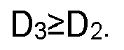
- The hot management component according to claim 6, wherein 2mm≤D2≤3mm.
- The hot management component according to claim 6 or 7, wherein 2mm≤D3≤4mm.
- A battery, comprisinga box;a battery cell housed within the box; andthe hot management component according to any one of claims 1 to 8, wherein the hot management component is arranged in the box, the battery cell is arranged in the accommodating space, and the hot management component is configured to manage a temperature of the battery cell.
- An electric device, comprising the battery according to claim 9, wherein the battery is configured to provide electrical energy.
- A manufacturing method of a hot management component, wherein the manufacturing method of the hot management component comprisesproviding a main body part, wherein the main body part is bent to form multiple connecting regions, and the multiple connecting regions are connected sequentially to form an accommodating space for accommodating battery cells; a connection position of two adjacent connecting regions forms a corner region, and an interior of the main body part is provided with a medium channel passing through the corner region; an opening is provided at a position corresponding to the medium channel on a side of the corner region away from the accommodating space; the opening is in communication with the medium channel;providing a shielding member; andconnecting the shielding member to the main body part so as to seal the opening.
- The manufacturing method of the hot management component according to claim 11, wherein the step of providing a main body part comprisesproviding a composite sheet, wherein an interior of the composite sheet forms the medium channel;arranging the opening on one side of the composite sheet in communication with the medium channel; andbending the composite sheet to form the main body part.
- The manufacturing method of the hot management component according to claim 12, wherein the providing a composite sheet comprisesproviding two sheets;stacking the two sheets and arranging a rolling inhibitor between the two sheets;hot rolling the two sheets to form a hot-rolled sheet; andexpanding the hot-rolled sheet, so as to enable the hot-rolled sheet to form the medium channel at a position where the rolling inhibitor is arranged, to form the composite sheet.
Applications Claiming Priority (1)
| Application Number | Priority Date | Filing Date | Title |
|---|---|---|---|
| PCT/CN2022/111492 WO2024031446A1 (en) | 2022-08-10 | 2022-08-10 | Thermal management component, manufacturing method therefor, battery, and electrical device |
Publications (2)
| Publication Number | Publication Date |
|---|---|
| EP4566738A1 true EP4566738A1 (en) | 2025-06-11 |
| EP4566738A4 EP4566738A4 (en) | 2026-01-14 |
Family
ID=89850232
Family Applications (1)
| Application Number | Title | Priority Date | Filing Date |
|---|---|---|---|
| EP22954421.8A Pending EP4566738A4 (en) | 2022-08-10 | 2022-08-10 | HEAT MANAGEMENT COMPONENT, MANUFACTURING METHOD FOR IT, BATTERY AND ELECTRICAL DEVICE |
Country Status (4)
| Country | Link |
|---|---|
| US (1) | US20250210754A1 (en) |
| EP (1) | EP4566738A4 (en) |
| CN (1) | CN223557118U (en) |
| WO (1) | WO2024031446A1 (en) |
Family Cites Families (7)
| Publication number | Priority date | Publication date | Assignee | Title |
|---|---|---|---|---|
| JP2008008598A (en) * | 2006-06-30 | 2008-01-17 | Calsonic Kansei Corp | Manufacturing method of tube for heat exchanger, and heat exchanger |
| CN203823418U (en) * | 2014-01-14 | 2014-09-10 | 四川长虹技佳精工有限公司 | Metal plate bending structure |
| CN209926945U (en) * | 2019-02-27 | 2020-01-10 | 常州恒创热管理有限公司 | Bent plate type heat pipe |
| CN111542202B (en) * | 2020-04-21 | 2021-05-14 | 华南理工大学 | A kind of inflatable soaking plate and its manufacturing method |
| CN112770612B (en) * | 2021-01-25 | 2022-09-16 | 深圳市飞荣达科技股份有限公司 | Edge-folded heat dissipation plate and machining method thereof |
| CN114071958B (en) * | 2021-11-05 | 2022-11-15 | 常州恒创热管理有限公司 | Heat dissipation device |
| CN113857798B (en) * | 2021-11-05 | 2022-11-18 | 常州恒创热管理有限公司 | Manufacturing method of radiator |
-
2022
- 2022-08-10 CN CN202290000905.7U patent/CN223557118U/en active Active
- 2022-08-10 WO PCT/CN2022/111492 patent/WO2024031446A1/en not_active Ceased
- 2022-08-10 EP EP22954421.8A patent/EP4566738A4/en active Pending
-
2025
- 2025-02-07 US US19/047,648 patent/US20250210754A1/en active Pending
Also Published As
| Publication number | Publication date |
|---|---|
| US20250210754A1 (en) | 2025-06-26 |
| WO2024031446A1 (en) | 2024-02-15 |
| CN223557118U (en) | 2025-11-18 |
| EP4566738A4 (en) | 2026-01-14 |
Similar Documents
| Publication | Publication Date | Title |
|---|---|---|
| US20250015426A1 (en) | Housing, battery cell, battery, and power consuming device | |
| CN116195118B (en) | Battery box, battery and power consumption device | |
| US20240250347A1 (en) | Battery cell, battery and electric-powered device | |
| CN216720173U (en) | Battery box, battery and power consumption device | |
| CN116250129A (en) | Battery cell, battery, electric device and battery manufacturing method and device | |
| WO2023000859A1 (en) | Battery cell, battery and power consuming device | |
| WO2023220882A1 (en) | End cover, battery cell, battery, and power consuming apparatus | |
| US20240347826A1 (en) | Shell, battery cell, battery and electricity consuming device | |
| US20240421400A1 (en) | Housing of battery, battery and power consumption device | |
| CN217485575U (en) | Battery case, battery and electrical device | |
| CN221447390U (en) | Housing, battery and power utilization device | |
| WO2024021293A1 (en) | Thermal management component, battery, and electrical device | |
| US12136741B2 (en) | Casing of battery, battery and electricity-consuming apparatus | |
| US20250087854A1 (en) | Battery cell, battery, and electric apparatus | |
| WO2023004724A1 (en) | Heat exchange member and manufacturing method therefor and manufacturing system thereof, battery, and electrical apparatus | |
| WO2024000086A1 (en) | Battery and electric apparatus | |
| WO2025208751A1 (en) | Battery and electric apparatus | |
| CN219476859U (en) | Battery box, battery and electrical device | |
| EP4566738A1 (en) | Thermal management component, manufacturing method therefor, battery, and electrical device | |
| CN116745987A (en) | Battery cells and manufacturing methods, manufacturing devices, batteries, and electrical devices | |
| CN221486708U (en) | Batteries and electrical devices | |
| CN220710429U (en) | Battery and electricity utilization device | |
| WO2025236401A1 (en) | Battery and electrical apparatus | |
| CN221928342U (en) | Battery box, battery and power consumption device | |
| CN219591573U (en) | Battery terminal plate, battery and electrical device |
Legal Events
| Date | Code | Title | Description |
|---|---|---|---|
| STAA | Information on the status of an ep patent application or granted ep patent |
Free format text: STATUS: THE INTERNATIONAL PUBLICATION HAS BEEN MADE |
|
| PUAI | Public reference made under article 153(3) epc to a published international application that has entered the european phase |
Free format text: ORIGINAL CODE: 0009012 |
|
| STAA | Information on the status of an ep patent application or granted ep patent |
Free format text: STATUS: REQUEST FOR EXAMINATION WAS MADE |
|
| 17P | Request for examination filed |
Effective date: 20250307 |
|
| AK | Designated contracting states |
Kind code of ref document: A1 Designated state(s): AL AT BE BG CH CY CZ DE DK EE ES FI FR GB GR HR HU IE IS IT LI LT LU LV MC MK MT NL NO PL PT RO RS SE SI SK SM TR |
|
| DAV | Request for validation of the european patent (deleted) | ||
| DAX | Request for extension of the european patent (deleted) | ||
| A4 | Supplementary search report drawn up and despatched |
Effective date: 20251212 |
|
| RIC1 | Information provided on ipc code assigned before grant |
Ipc: B21D 53/02 20060101AFI20251208BHEP Ipc: B23P 15/26 20060101ALI20251208BHEP |