EP4566703A1 - Mixed gas distribution system and ammonia synthesis system comprising mixed gas distribution system - Google Patents
Mixed gas distribution system and ammonia synthesis system comprising mixed gas distribution system Download PDFInfo
- Publication number
- EP4566703A1 EP4566703A1 EP24217667.5A EP24217667A EP4566703A1 EP 4566703 A1 EP4566703 A1 EP 4566703A1 EP 24217667 A EP24217667 A EP 24217667A EP 4566703 A1 EP4566703 A1 EP 4566703A1
- Authority
- EP
- European Patent Office
- Prior art keywords
- mixed gas
- ammonia synthesis
- gas distribution
- flow pipe
- gas flow
- Prior art date
- Legal status (The legal status is an assumption and is not a legal conclusion. Google has not performed a legal analysis and makes no representation as to the accuracy of the status listed.)
- Granted
Links
Images



Classifications
-
- B—PERFORMING OPERATIONS; TRANSPORTING
- B01—PHYSICAL OR CHEMICAL PROCESSES OR APPARATUS IN GENERAL
- B01J—CHEMICAL OR PHYSICAL PROCESSES, e.g. CATALYSIS OR COLLOID CHEMISTRY; THEIR RELEVANT APPARATUS
- B01J4/00—Feed or outlet devices; Feed or outlet control devices
- B01J4/001—Feed or outlet devices as such, e.g. feeding tubes
- B01J4/004—Sparger-type elements
-
- C—CHEMISTRY; METALLURGY
- C01—INORGANIC CHEMISTRY
- C01C—AMMONIA; CYANOGEN; COMPOUNDS THEREOF
- C01C1/00—Ammonia; Compounds thereof
- C01C1/02—Preparation, purification or separation of ammonia
- C01C1/04—Preparation of ammonia by synthesis
- C01C1/0405—Preparation of ammonia by synthesis from N2 and H2 in presence of a catalyst
- C01C1/0417—Preparation of ammonia by synthesis from N2 and H2 in presence of a catalyst characterised by the synthesis reactor, e.g. arrangement of catalyst beds and heat exchangers in the reactor
-
- B—PERFORMING OPERATIONS; TRANSPORTING
- B01—PHYSICAL OR CHEMICAL PROCESSES OR APPARATUS IN GENERAL
- B01J—CHEMICAL OR PHYSICAL PROCESSES, e.g. CATALYSIS OR COLLOID CHEMISTRY; THEIR RELEVANT APPARATUS
- B01J8/00—Chemical or physical processes in general, conducted in the presence of fluids and solid particles; Apparatus for such processes
- B01J8/0005—Catalytic processes under superatmospheric pressure
-
- B—PERFORMING OPERATIONS; TRANSPORTING
- B01—PHYSICAL OR CHEMICAL PROCESSES OR APPARATUS IN GENERAL
- B01J—CHEMICAL OR PHYSICAL PROCESSES, e.g. CATALYSIS OR COLLOID CHEMISTRY; THEIR RELEVANT APPARATUS
- B01J8/00—Chemical or physical processes in general, conducted in the presence of fluids and solid particles; Apparatus for such processes
- B01J8/02—Chemical or physical processes in general, conducted in the presence of fluids and solid particles; Apparatus for such processes with stationary particles, e.g. in fixed beds
- B01J8/0242—Chemical or physical processes in general, conducted in the presence of fluids and solid particles; Apparatus for such processes with stationary particles, e.g. in fixed beds the fluid flow within the bed being predominantly vertical
- B01J8/0257—Chemical or physical processes in general, conducted in the presence of fluids and solid particles; Apparatus for such processes with stationary particles, e.g. in fixed beds the fluid flow within the bed being predominantly vertical in a cylindrical annular shaped bed
-
- B—PERFORMING OPERATIONS; TRANSPORTING
- B01—PHYSICAL OR CHEMICAL PROCESSES OR APPARATUS IN GENERAL
- B01J—CHEMICAL OR PHYSICAL PROCESSES, e.g. CATALYSIS OR COLLOID CHEMISTRY; THEIR RELEVANT APPARATUS
- B01J8/00—Chemical or physical processes in general, conducted in the presence of fluids and solid particles; Apparatus for such processes
- B01J8/02—Chemical or physical processes in general, conducted in the presence of fluids and solid particles; Apparatus for such processes with stationary particles, e.g. in fixed beds
- B01J8/0278—Feeding reactive fluids
-
- C—CHEMISTRY; METALLURGY
- C01—INORGANIC CHEMISTRY
- C01C—AMMONIA; CYANOGEN; COMPOUNDS THEREOF
- C01C1/00—Ammonia; Compounds thereof
- C01C1/02—Preparation, purification or separation of ammonia
- C01C1/04—Preparation of ammonia by synthesis
- C01C1/0405—Preparation of ammonia by synthesis from N2 and H2 in presence of a catalyst
- C01C1/0411—Preparation of ammonia by synthesis from N2 and H2 in presence of a catalyst characterised by the catalyst
-
- C—CHEMISTRY; METALLURGY
- C01—INORGANIC CHEMISTRY
- C01C—AMMONIA; CYANOGEN; COMPOUNDS THEREOF
- C01C1/00—Ammonia; Compounds thereof
- C01C1/02—Preparation, purification or separation of ammonia
- C01C1/04—Preparation of ammonia by synthesis
- C01C1/0405—Preparation of ammonia by synthesis from N2 and H2 in presence of a catalyst
- C01C1/0447—Apparatus other than synthesis reactors
-
- B—PERFORMING OPERATIONS; TRANSPORTING
- B01—PHYSICAL OR CHEMICAL PROCESSES OR APPARATUS IN GENERAL
- B01J—CHEMICAL OR PHYSICAL PROCESSES, e.g. CATALYSIS OR COLLOID CHEMISTRY; THEIR RELEVANT APPARATUS
- B01J2208/00—Processes carried out in the presence of solid particles; Reactors therefor
- B01J2208/00796—Details of the reactor or of the particulate material
- B01J2208/00893—Feeding means for the reactants
- B01J2208/00911—Sparger-type feeding elements
-
- B—PERFORMING OPERATIONS; TRANSPORTING
- B01—PHYSICAL OR CHEMICAL PROCESSES OR APPARATUS IN GENERAL
- B01J—CHEMICAL OR PHYSICAL PROCESSES, e.g. CATALYSIS OR COLLOID CHEMISTRY; THEIR RELEVANT APPARATUS
- B01J2208/00—Processes carried out in the presence of solid particles; Reactors therefor
- B01J2208/00796—Details of the reactor or of the particulate material
- B01J2208/00893—Feeding means for the reactants
- B01J2208/0092—Perforated plates
-
- B—PERFORMING OPERATIONS; TRANSPORTING
- B01—PHYSICAL OR CHEMICAL PROCESSES OR APPARATUS IN GENERAL
- B01J—CHEMICAL OR PHYSICAL PROCESSES, e.g. CATALYSIS OR COLLOID CHEMISTRY; THEIR RELEVANT APPARATUS
- B01J2208/00—Processes carried out in the presence of solid particles; Reactors therefor
- B01J2208/00796—Details of the reactor or of the particulate material
- B01J2208/00938—Flow distribution elements
-
- Y—GENERAL TAGGING OF NEW TECHNOLOGICAL DEVELOPMENTS; GENERAL TAGGING OF CROSS-SECTIONAL TECHNOLOGIES SPANNING OVER SEVERAL SECTIONS OF THE IPC; TECHNICAL SUBJECTS COVERED BY FORMER USPC CROSS-REFERENCE ART COLLECTIONS [XRACs] AND DIGESTS
- Y02—TECHNOLOGIES OR APPLICATIONS FOR MITIGATION OR ADAPTATION AGAINST CLIMATE CHANGE
- Y02P—CLIMATE CHANGE MITIGATION TECHNOLOGIES IN THE PRODUCTION OR PROCESSING OF GOODS
- Y02P20/00—Technologies relating to chemical industry
- Y02P20/50—Improvements relating to the production of bulk chemicals
- Y02P20/52—Improvements relating to the production of bulk chemicals using catalysts, e.g. selective catalysts
Definitions
- the present disclosure relates generally to a mixed gas distribution system, in particular to an ammonia synthesis system comprising such mixed gas distribution system.
- the ammonia synthesis system of the present disclosure is particulalry suited for using a feed gas generated with energy from a renewable energy power source.
- renewable energy there is an increasing need for renewable energy to achieve a greenhouse gas reduction to cope with climate change and depletion of oil resources.
- areas that meet an appropriate condition for renewable energy production are scattered, and it is thus essential to find means and ways for storing and transporting renewable energy.
- renewable energy which is abundant in the equatorial and southern hemisphere areas, is required to be transported to the northern hemisphere where renewable energy is highly demanded.
- ammonia is spotlighted as an energy carrier to solve the problems occurring from the area ubiquity and temporal variability of renewable energy.
- ammonia may be liquefied at room temperature and at pressures of 8.5 atmospheres or lower, and thus be stored and transported more easily than hydrogen. Therefore, as an alternative to solve the problems occurring from the area ubiquity and temporal variability of renewable energy, there is a need for synthesizing ammonia from hydrogen and nitrogen produced using electricity from renewable energy.
- hydrogen one of the main raw material for the ammonia synthesis
- a water electrolyzer powered by renewable energy such as solar or wind energy.
- renewable energy such as, for example, solar energy or wind energy
- the amount of hydrogen (e.g., flow rate) provided by a process using renewable solar or wind energy may vary or fluctuate significantly and, hence, an ammonia synthesis system using such hydrogen cannot be operated at a constant flow rate. Such changes may have a negative impact on the overall efficiency of the ammonia synthesis system.
- a flow rate distribution upstream of a catalyst bed included in an ammonia synthesis reactor may get more and more less uniform when a flow rate of the raw material such as hydrogen fed into the ammonia synthesis system decreases or increases.
- a temperature deviation may occur between the central and outer parts of the catalyst bed especially at the beginning of its operation, which may reduce an ammonia synthesis yield.
- ammonia synthesis system which can operate efficiently with hydrogen from a renewable energy process.
- the ammonia synthesis system will need to be able to cope with the changes in the flow rate that occurs during the production cycle, while solving the problems of the non-uniform flow rate distribution that occurs upstream of the catalyst bed and the reduced ammonia synthesis yield caused by the temperature deviation between the central and outer parts of the catalyst bed at the beginning of the operation.
- An embodiment of the present disclosure is directed to providing an ammonia synthesis system which may cope with significant changes in a raw material flow rate that occur during a production cycle.
- Another embodiment of the present disclosure is directed to providing a mixed gas distribution system and an ammonia synthesis system which may maintain a uniform flow rate distribution before a catalyst bed included in an ammonia synthesis reactor even when a flow rate of a raw material, such as hydrogen, fed into the ammonia synthesis system is decreased.
- An embodiment of the present disclosure is directed to providing a mixed gas distribution system and an ammonia synthesis system having excellent mixing efficiency of hydrogen and nitrogen, which are ammonia synthesis raw materials.
- Another embodiment of the present disclosure is directed to providing an ammonia synthesis system which may improve an ammonia synthesis yield by enabling a temperature deviation between the central and outer parts of a catalyst bed to be uniform at the beginning of its operation.
- Still another embodiment of the present disclosure is directed to providing an ammonia synthesis system which may improve an ammonia synthesis yield at the beginning of its operation by preheating a catalyst bed at the beginning of its operation.
- Another embodiment of the present disclosure is directed to providing an ammonia synthesis system which may save energy by optimizing an amount of energy required by the system during its operation.
- Another embodiment of the present disclosure is directed to providing an ammonia synthesis system which may increase a catalyst replacement cycle by uniformly using each catalyst bed during the operation.
- a mixed gas distribution system comprising a gas distribution device; a mixed gas supply line connected to the gas distribution device; a flow induction guide; an upper area; and a plurality of mixed gas flow pipes fixed to a circumference part of a bottom surface of the upper area, and connected to a plurality of openings formed in the circumference part of the bottom surface to enable a movement of mixed gas, wherein the gas distribution device is installed horizontally, a plurality of mixed gas distribution openings are formed in an outer surface of the gas distribution device and distribute the mixed gas, the upper area has the bottom surface and a side surface connecting the bottom surface with an upper wall inside an ammonia synthesis reactor, a circular opening is formed in a center of the bottom surface of the upper area, the flow induction guide has a side surface connecting an upper circumference of an inner drum included in the reactor with a circumference of the circular opening formed in the center of the bottom surface of the upper area, a fixation bracket is disposed on an inner surface of the flow induction guide, and the gas distribution device
- the mixed gas flow pipe may have a bottom surface and a side surface connecting the bottom surface with the opening formed in the circumference part of the bottom surface of the upper area, a plurality of upper openings may be formed in a side surface of an upper part of the mixed gas flow pipe spaced apart from each other along a circumference of the pipe, a plurality of middle openings may be formed in a side surface of a middle part of the mixed gas flow pipe spaced apart from each other along the circumference, and a plurality of lower openings may be formed in a side surface of a lower part of the mixed gas flow pipe spaced apart from each other along the circumference, and the mixed gas flow pipe may include a cover surrounding at least some regions of the side surface of the mixed gas flow pipe to provide a space for a fluid flowing out of the side surface of the mixed gas flow pipe after passing through the upper opening to be guided toward the middle opening.
- the mixed gas flow pipe may further include a separator plate dividing the upper and middle parts of the mixed gas flow pipe from each other.
- a preferable use of the above described mixed gas distribution system may be in a ammonia synthesis reactor.
- the gas distribution device may have a toroidal shape.
- the cooling mixed gas may be supplied from the mixed gas supply line.
- a conical flow inducer may be disposed at a center of the upper wall inside the reactor.
- the mixed gas supply lines may include a flow regulating device.
- a distribution plate may be installed horizontally above an upper surface of the inner drum.
- the distribution plate includes a plurality of openings.
- an ammonia synthesis system including the ammonia synthesis reactor; the mixed gas distribution system, which is included in the ammonia synthesis reactor; and one or more catalyst beds disposed downstream from the mixed gas distribution system.
- a heat exchanger may be disposed downstream from the catalyst bed in order to remove heat from an effluent of the catalyst bed. Further or alternatively, the heat exchanger may surround the catalyst bed or its surroundings.
- a method for ammonia synthesis wherein the ammonia synthesis system disclosed herein is used.
- Ammonia may be synthesized in the ammonia synthesis system and in the method at 10 to 300 bar.
- Ammonia may be synthesized in the ammonia synthesis system and in the method at 200 to 700°C.
- an ammonia synthesis system comprising: an ammonia synthesis reactor; a mixed gas distribution system as mentioned above included in an ammonia synthesis reactor; an eco-friendly process for making the hydrogen using renewable energy and supplying the hydrogen to the mixed gas distribution system, and one or more catalyst beds disposed downstream from the mixed gas distribution system inside the ammonia synthesis reactor.
- a numerical range used in the specification may include the lower and upper limits and all values within that range, increments logically derived from the shape and width of the defined range, all values delimited by those limits, and all possible combinations of the upper and lower limits of a numerical range delimited by different shapes.
- the defined numerical range may also include values outside the numerical range, which may occur due to experimental errors or rounding of values unless otherwise specified in the specification.
- a term "to include” or “to comprise” in the specification is a comprehensive description that has the meaning equivalent to an expression such as “to include”, “to comprise”, “to contain”, “to have”, or “to be featured”, and does not exclude an element, a material, or a process that is not additionally enumerated.
- upper generally means a spatial distribution in a longitudinal direction of the system; these terms may refer to a separation of the corresponding element in a direction of stream (downstream or upstream), regardless whether a system having a certain longitudinal shape is arranged in an upward/vertical orientation or in a horizontal orientation.
- a unit of % used in the specification may indicate % by weight.
- An embodiment of the present disclosure may provide a mixed gas distribution system including a gas distribution device; a mixed gas supply line connected to the gas distribution device; a flow induction guide; an upper area; and a plurality of mixed gas flow pipes fixed to a circumference part of a bottom surface of the upper area, and connected to a plurality of openings formed in the circumference part of the bottom surface to enable a movement of mixed gas, wherein the gas distribution device is installed horizontally, a plurality of mixed gas distribution openings are formed in an outer surface of the gas distribution device and distribute the mixed gas, the upper area has the bottom surface and a side surface connecting the bottom surface with an upper wall inside an ammonia synthesis reactor, a circular opening is formed in the center of the bottom surface of the upper area, the flow induction guide has a side surface connecting an upper circumference of an inner drum included in the reactor with a circumference of the circular opening formed in the center of the bottom surface of the upper area, a fixation bracket is disposed on an inner surface of the flow induction guide, and the gas distribution
- the mixed gas distribution system and an ammonia synthesis system comprising the mixed gas distribution system according to an embodiment of the present disclosure may maintain a uniform flow rate distribution upstream of a catalyst bed included in the ammonia synthesis reactor even when a flow rate of a raw material, such as hydrogen, fed into the ammonia synthesis system is decreased.
- the mixed gas distribution system and the ammonia synthesis system may achieve excellent mixing efficiency of hydrogen and nitrogen, which are the raw materials for synthesizing ammonia.
- the mixed gas distribution system may include a gas distribution device 1; a mixed gas supply line 2 connected to the gas distribution device 1; a flow induction guide 3; an upper area 4; and a plurality of mixed gas flow pipes 5 fixed to a circumference part of a bottom surface 401 of the upper area 4, and connected to a plurality of openings 407 formed in the circumference part of the bottom surface 401 to enable the movement of the mixed gas.
- Each of the plurality of openings 407 may (optionally) correlate with the mixed gas flow pipe 5 located respectively below each opening 407 for gas flow.
- the gas distribution device 1 may be installed horizontally, and a plurality of mixed gas distribution openings 101 for distributing the mixed gas may be formed in an outer surface of the gas distribution device 1.
- the mixed gas, supplied through the mixed gas supply line 2, may be distributed into the ammonia synthesis reactor through the mixed gas distribution openings 101.
- the gas distribution device 1 may uniformly mix the mixed gas flowing in from an inner drum 7 with the mixed gas supplied from the mixed gas supply line 2.
- the mixed gas distribution openings 101 may distribute the mixed gas upward or downward, however, the embodiments are not be limited in this way.
- the mixed gas distribution openings are spaced apart from each other and may be arranged in any suitable pattern.
- the upper area 4 may have the bottom surface 401 and a side surface 403 connecting the bottom surface 401 with the upper wall inside the reactor, and a circular opening 405 may be formed in the center of the bottom surface 401 of the upper area 4.
- the mixed gas introduced from the inner drum 7 and the mixed gas supplied from the mixed gas supply line 2 may flow into the upper area 4 through the flow induction guide 3 and may then be directed toward the side surface of the upper area 4 and pass through the plurality of openings 407 to thus flow into the plurality of mixed gas flow pipes 5.
- the flow induction guide 3 may have a side surface 301 connecting an upper circumference of the inner drum 7 included in the reactor with the circumference of the circular opening 405 formed in the center of the bottom surface 401 of the upper area 4.
- the flow induction guide 3 may include a fixation bracket 303 disposed on an inner surface of the flow induction guide 3 for supporting the gas distribution device 1. The mixed gas flowing in from the inner drum 7 and the mixed gas supplied from the mixed gas supply line 2 may flow into the upper area 4 along the flow induction guide 3.
- the gas distribution device 1 may be supported by the fixation bracket 303.
- the fixation bracket 303 is configured to provide support for the gas distribution device creating a ring-shape support structure along the internal circumference of the flow induction guide 3.
- the ring shaped fixation bracket 303 may have a small width to leave most of the cross-sectional area of the flow induction guide 3 open for the mixed gas flow to pass through unobstructed and reach the mixed gas distribution device 1.
- the mixed gas flow may then flow through the mixed gas distribution openings 101 toward the upper area 4 of the mixed gas distribution system.
- the mixed gas may then pass through the plurality of openings 407 of the bottom surface 401 of the upper area 4 into the mixed gas flow pipes 5.
- a distribution plate 8 may be installed horizontally above an upper surface of the inner drum 7.
- the distribution plate 8 may be installed on the upper surface of the inner drum 7.
- the distribution plate 8 may include a plurality of openings 8a. Through the openings 8a of the distribution plate 8, the mixed gas may uniformly flow in from the inner drum 7 to the flow induction guide 3 of the mixed gas distribution system.
- each of the mixed gas flow pipes 5 may have a bottom surface 521 and a side surface 522 (522a, 522b, 522c) connecting the bottom surface 521 with the corresponding opening 407 formed in the circumference part of the bottom surface of the upper area 4.
- the bottom surface 521 of the mixed gas flow pipe may be a plate without any openings.
- a plurality of upper openings 523 may be formed in a side surface of an upper part 522a of the mixed gas flow pipe 5 spaced apart from each other along a circumference of the pipe 5.
- a plurality of middle openings 525 may be formed in a side surface of a middle part 522b of the mixed gas flow pipe 5 spaced apart from each other along the circumference of the middle part 522b of the mixed gas flow pipe 5.
- a plurality of lower openings 527 may be formed in a side surface of a lower part 522c of the mixed gas flow pipe 5 spaced apart from each other along the circumference of the lower part 522c of the mixed gas flow pipe 5.
- a flow of the mixed gas may be formed through the upper openings 523, the middle openings 525, and the lower openings 527.
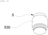
- the mixed gas flow pipe 5 may include a cover 530 surrounding at least some regions of the side surface of the mixed gas flow pipe 5 to provide a space for a fluid flowing out of the side surface of the mixed gas flow pipe 5 after passing through the upper openings 523 to be guided toward the middle openings 525.
- the cover 530 may surround at least one selected from the group consisting of the upper and middle parts of the side surface of the mixed gas flow pipe 5.
- the cover 530 may cause the fluid flowing out of the side surface of the mixed gas flow pipe 5 after passing through the upper openings 523 to be guided toward the middle openings 525.
- This configuration may form a flow in which the fluid is moved to the outside of the side surface of the mixed gas flow pipe 5 and then moved back to the inside of the side surface.
- the fluids may be mixed more effectively and smoothly with each other.
- Better mixing is highly beneficial because it can increase the reaction rate and overall business efficiency. Better mixing can also improve catalyst utilization and reduce catalyst hot spots.
- the mixed gas flow pipe 5 may further include a separator plate 529 dividing the upper and middle parts of the mixed gas flow pipe 5 from each other.
- the separator plate 529 may completely separate the upper and middle parts of the mixed gas flow pipe 5 from each other to prevent the movement of the fluid. More specifically, the separator plate forces the fluid flow of the mixed gas which enters a mixed gas flow pipe 5 to exit the upper part of the mixed gas flow pipe 5 through the upper openings 523 into the side space created by the cover 530 and then back into the middle part of the mixed gas flow pipe 5 through the middle openings 525.
- the fluid flowing into the upper part of the mixed gas flow pipe 5 may flow out through the upper openings 523 into the space between the mixed gas flow pipe 5 and the cover 530 rather than descending directly to the middle part, by the separator plate 529.
- the fluid in the space may then flow into the mixed gas flow pipe through the middle openings 525, descend downwards, and flow out of the mixed gas flow pipe 5 through the lower openings 527.
- the fluid in the lower part of the mixed gas flow pipe 5 may not exit via the bottom surface 521 of the mixed gas flow pipe 5 and is forced to exit via the lower openings 527.
- the fluid may form the flow in which the fluid flows out of the mixed gas flow pipe 5, flows back into the inside of the pipe, and flows out of the pipe again, thereby improving mixing efficiency of hydrogen and nitrogen, which are the ammonia synthesis raw materials, and maintaining the uniform flow rate distribution before the catalyst bed.
- the mixing is accomplished passively in a consistent manner without any moving mechanical parts.
- the side surface (522) may be divided into the side surface of the upper part (522a), the side surface of the middle part (522b), the side surface of the lower part (522c).
- the mixed gas flow pipe 5 may be disposed above a catalyst bed 6.
- the mixed gas flow pipes 5 may be disposed above the catalyst bed, thus enabling the mixed gas passing through the mixed gas flow pipe 5 to be uniformly distributed to the catalyst bed 6. This configuration may improve an ammonia synthesis yield and extend a lifespan of the catalyst bed.
- the mixed gas distribution system may be used for the ammonia synthesis reactor.
- the mixed gas distribution system may maintain the uniform flow rate distribution before the catalyst bed included in the ammonia synthesis reactor even when the flow rate of the raw material, such as hydrogen, fed into the ammonia synthesis reactor is decreased especially when the mixed gas distribution system is included in the ammonia synthesis reactor, and may achieve excellent mixing efficiency of hydrogen and nitrogen, which are the ammonia synthesis raw materials.
- the gas distribution device 1 may have a toroidal shape. In another embodiment according to the present disclosure, the gas distribution device 1 may have a disk shape. However, it is noted that the embodiments may not be limited in this way and generally any suitable conventional gas distribution device may also be used.
- the mixed gas may include at least one selected from the group consisting of hydrogen and nitrogen.
- hydrogen the main raw material for the ammonia synthesis
- a water electrolyzer powered by renewable energy may be produced by a water electrolyzer powered by renewable energy.
- renewable energy such as, for example, solar energy or wind energy are not constant or available at all times. Therefore, the amount of hydrogen (e.g., flow rate) provided by a process using renewable energy (e.g., solar or wind energy) may vary or fluctuate significantly and, hence, an ammonia synthesis system using such hydrogen cannot be operated at a constant flow rate. Such changes may have a negative impact on the overall efficiency of the ammonia synthesis system.
- hydrogen may be produced by a water electrolyzer powered using renewable energy.
- Renewable energy may include at least one selected from the group consisting of solar energy, photovoltaic energy, bioenergy, wind energy, hydroelectric energy, geothermal energy, ocean energy, and waste energy.
- Renewable energy shows temporal variability. For example, the solar energy is unable to be used at night. Therefore, when hydrogen is produced using the device powered by renewable energy, the ammonia synthesis system is unable to be always operated at a constant flow rate. That is, there is a need for the ammonia synthesis system to cope with a change in the flow rate that occurs during a production cycle due to the temporal variability of renewable energy.
- the mixed gas supplied from the mixed gas supply line 2 may be the cooling mixed gas having a low temperature. Therefore, the mixed gas supplied through the mixed gas supply line 2 may function as the cooling mixed gas, and may also function as a means of cooling the mixed gas flowing in the ammonia synthesis system.
- the cooling mixed gas may be used as the cooling means to cool the mixed gas fed into the catalyst bed.
- the mixed gas distribution system may have a conical flow inducer 9 disposed at the center of the upper wall inside the reactor.
- the conical flow inducer 9 may function as a pre-diffuser for deflecting the mixed gas for the mixed gas entering the upper area 4 to flow smoothly toward the plurality of openings 407, prevent a dead zone from occurring in the upper area 4, and distribute the mixed gas uniformly to the plurality of openings.
- the mixed gas supply line 2 may include a flow regulating device.
- the flow regulating device may enable the flow rate of the mixed gas to be controlled independently in the mixed gas supply line 2.
- the flow regulating device may independently regulate the flow rate of the mixed gas flowing through the mixed gas supply line 2 for the flow rate of the mixed gas entering the gas distribution device to be maintained within a desired flow rate range.
- the mixed gas distribution system and the ammonia synthesis system comprising the mixed gas distribution system according to an embodiment of the present disclosure may cope with the change in the flow rate occurring during the production cycle, and maintain the uniform flow rate distribution before the catalyst bed included in the ammonia synthesis reactor even when the flow rate of a raw material feed, such as hydrogen, is decreased.
- the flow regulating device may be a flow regulating valve.
- the flow rate of the raw material feed (e.g., the hydrogen and nitrogen feed, also referred to as the mixed gas flow rate.) that can be changed during the production cycle may be classified into three levels, or categories for convenience. As described above, the raw material flow rate may be classified into a low flow rate, a medium flow rate, and a high flow rate. However, the change in the flow rate may be easily regulated by the common sense or judgment of those skilled in the art.
- the low flow rate case indicates a case where the flow rate of the mixed gas feed flow results in an ammonia produced is less than half (50%) of an annual average production flow rate (100%)
- the medium flow rate case indicates a case where the flow rate is half (50%) or more and less than twice (200%) of the annual average production flow rate (100%)
- the high flow rate case indicates a case where the flow rate is more than twice (200%) of the annual average production flow rate (100%), but the embodiments are not limited thereto.
- the mixed gas supply line 2 may branch from one main mixed gas supply line.
- the mixed gas supply line 2 may receive at least one gas selected from the group consisting of nitrogen and hydrogen from each of individual nitrogen and hydrogen supply lines.
- the embodiments of the present disclosure may provide the ammonia synthesis system comprising the mixed gas distribution system.
- the same description may be applied to a content of the mixed gas distribution system overlapping a content of the ammonia synthesis system.
- An embodiment of the present disclosure may provide the ammonia synthesis system including an ammonia synthesis reactor; the mixed gas distribution system described above, which is included in the ammonia synthesis reactor; and one or more catalyst beds 6 disposed downstream of the mixed gas distribution system.
- the ammonia synthesis system may maintain the uniform flow rate distribution upstream of the catalyst bed or beds included in the ammonia synthesis reactor even when the flow rate of a raw material feed, such as hydrogen, is decreased.
- ammonia synthesis system may achieve the excellent mixing efficiency of hydrogen and nitrogen, which are the ammonia synthesis raw materials.
- the catalyst bed 6 may be installed in a toroidal area formed between the inner drum 7 and an outer side wall of the ammonia synthesis reactor 10.
- the mixed gas passed through the mixed gas flow pipe 5 may flow down along the outer side wall of the ammonia synthesis reactor to reach the catalyst bed 6.
- the mixed gas flow pipes 5 may be disposed above the catalyst bed 6.
- the mixed gas flow pipes 5 may be disposed above the catalyst bed, thus enabling the mixed gas passed through the mixed gas flow pipes 5 to be uniformly distributed to the catalyst bed. This configuration may improve the ammonia synthesis yield and extend the lifespan of the catalyst bed.
- the ammonia synthesis system may further include a microwave heating device.
- the ammonia synthesis system may further include the microwave heating device to thus enable a temperature deviation between the central and outer parts of the catalyst bed 6 to be reduced or eliminated resulting in a uniform temperature along the catalyst bed 6 at the beginning of its operation, thereby improving the ammonia synthesis yield.
- the microwave heating device may enable the temperature deviation between the central and outer parts of the catalyst bed to be eliminated and the temperature may become uniform by emitting the microwaves to the catalyst bed 6 at the beginning of the operation.
- the microwave heating device may improve the ammonia synthesis yield at the beginning of the operation by preheating the catalyst bed that is not sufficiently preheated at the beginning of the operation.
- One or more heating devices may be installed on each catalyst bed. For example, one, two or more, three or more, four or more, five or more, ... or eight or more microwave heating devices may be installed on each catalyst bed. It is noted, however, that the number of microwave heating devices is not limited thereto. The number of the microwave heating devices may be increased based on a size of the reactor and the catlayst beds 6 inside the reactor. Also, an installation location of the microwave heating device may be adjusted for efficient microwave emission.
- the ammonia synthesis system may further include a microwave guide.
- a microwave guide for each microwave device.
- Each microwave guide may enable the microwaves emitted by a corresponding microwave heating device to reach the catalyst bed more efficiently.
- the shape or installation location of the guides may be changed, amongst other considerations, based on a microwave waveform.
- the number of catalyst beds 6 may be one or more. In an embodiment according to the present disclosure, the number of catalyst beds 6 may be one or more, two or more, three or more, four or more, five or more, six or more, seven or more, eight or more, nine or more, ten or more, twenty or fewer, ten or fewer, nine or fewer, eight or fewer, seven or fewer, six or fewer, five or fewer, four or fewer, three or fewer, two or fewer, one or fewer, or a value between these values.
- ammonia may be synthesized at 1 to 500 bar or 10 to 300 bar in a respective method.
- ammonia may be synthesized at 100 to 800°C or 200 to 700°C in a respective method.
- the ammonia synthesis system may further include a heat exchanger disposed downstream from the catalyst bed 6 to remove heat from an effluent of the catalyst bed.
- the heat exchanger may surround the catalyst bed or its surroundings.
- the ammonia synthesis system according to the present disclosure may include an additional heat removal means other than the supply of the cooling the mixed gas by further including the heat exchanger. This configuration may enable the flexible operation of the ammonia synthesis system.
- ammonia synthesis system may cope with the change in the flow rate that occurs during the production cycle.
- the mixed gas distribution system and the ammonia synthesis system may maintain the uniform flow rate distribution before the catalyst bed included in the ammonia synthesis reactor even when the flow rate of the raw material, such as hydrogen, fed into the ammonia synthesis system is decreased.
- the mixed gas distribution system and the ammonia synthesis system according to an embodiment of the present disclosure may achieve excellent mixing efficiency of hydrogen and nitrogen, which are the raw materials for synthesizing ammonia.
- the ammonia synthesis system may improve the ammonia synthesis yield by enabling the temperature deviation between the central and outer parts of the catalyst bed to be eliminated and a uniform temperature to be obtained at the beginning of its operation.
- the ammonia synthesis system may improve the ammonia synthesis yield at the beginning of its operation by preheating the catalyst bed at the beginning of its operation.
- the ammonia synthesis system according to an embodiment of the present disclosure may synthesize ammonia in the eco-friendly manner.
Landscapes
- Chemical & Material Sciences (AREA)
- Organic Chemistry (AREA)
- Chemical Kinetics & Catalysis (AREA)
- Analytical Chemistry (AREA)
- Inorganic Chemistry (AREA)
- Physics & Mathematics (AREA)
- Fluid Mechanics (AREA)
- Devices And Processes Conducted In The Presence Of Fluids And Solid Particles (AREA)
Abstract
Description
- The present disclosure relates generally to a mixed gas distribution system, in particular to an ammonia synthesis system comprising such mixed gas distribution system. The ammonia synthesis system of the present disclosure is particulalry suited for using a feed gas generated with energy from a renewable energy power source.
- There is an increasing need for renewable energy to achieve a greenhouse gas reduction to cope with climate change and depletion of oil resources. However, areas that meet an appropriate condition for renewable energy production are scattered, and it is thus essential to find means and ways for storing and transporting renewable energy. For example, renewable energy, which is abundant in the equatorial and southern hemisphere areas, is required to be transported to the northern hemisphere where renewable energy is highly demanded.
- In addition, renewable energy has temporal variability, thus making an electric storage device essential. Ammonia is spotlighted as an energy carrier to solve the problems occurring from the area ubiquity and temporal variability of renewable energy. In particular, ammonia may be liquefied at room temperature and at pressures of 8.5 atmospheres or lower, and thus be stored and transported more easily than hydrogen. Therefore, as an alternative to solve the problems occurring from the area ubiquity and temporal variability of renewable energy, there is a need for synthesizing ammonia from hydrogen and nitrogen produced using electricity from renewable energy.
- For example, hydrogen, one of the main raw material for the ammonia synthesis, may be produced by a water electrolyzer powered by renewable energy such as solar or wind energy. One issue that needs to be addressed is that renewable energy, such as, for example, solar energy or wind energy is not constant or available at all times. Therefore, the amount of hydrogen (e.g., flow rate) provided by a process using renewable solar or wind energy may vary or fluctuate significantly and, hence, an ammonia synthesis system using such hydrogen cannot be operated at a constant flow rate. Such changes may have a negative impact on the overall efficiency of the ammonia synthesis system.
- In addition, a flow rate distribution upstream of a catalyst bed included in an ammonia synthesis reactor may get more and more less uniform when a flow rate of the raw material such as hydrogen fed into the ammonia synthesis system decreases or increases.
- In addition, in a conventional ammonia synthesis system, a temperature deviation may occur between the central and outer parts of the catalyst bed especially at the beginning of its operation, which may reduce an ammonia synthesis yield.
- Therefore, there is a need for an ammonia synthesis system which can operate efficiently with hydrogen from a renewable energy process. The ammonia synthesis system will need to be able to cope with the changes in the flow rate that occurs during the production cycle, while solving the problems of the non-uniform flow rate distribution that occurs upstream of the catalyst bed and the reduced ammonia synthesis yield caused by the temperature deviation between the central and outer parts of the catalyst bed at the beginning of the operation.
- Thus, there is a need for a mixed gas distribution system and an ammonia synthesis system which may solve these problems.
- An embodiment of the present disclosure is directed to providing an ammonia synthesis system which may cope with significant changes in a raw material flow rate that occur during a production cycle.
- Another embodiment of the present disclosure is directed to providing a mixed gas distribution system and an ammonia synthesis system which may maintain a uniform flow rate distribution before a catalyst bed included in an ammonia synthesis reactor even when a flow rate of a raw material, such as hydrogen, fed into the ammonia synthesis system is decreased.
- An embodiment of the present disclosure is directed to providing a mixed gas distribution system and an ammonia synthesis system having excellent mixing efficiency of hydrogen and nitrogen, which are ammonia synthesis raw materials.
- Another embodiment of the present disclosure is directed to providing an ammonia synthesis system which may improve an ammonia synthesis yield by enabling a temperature deviation between the central and outer parts of a catalyst bed to be uniform at the beginning of its operation.
- Still another embodiment of the present disclosure is directed to providing an ammonia synthesis system which may improve an ammonia synthesis yield at the beginning of its operation by preheating a catalyst bed at the beginning of its operation.
- Another embodiment of the present disclosure is directed to providing an ammonia synthesis system which may save energy by optimizing an amount of energy required by the system during its operation.
- Another embodiment of the present disclosure is directed to providing an ammonia synthesis system which may increase a catalyst replacement cycle by uniformly using each catalyst bed during the operation.
- In one embodiment, provided is a mixed gas distribution system comprising a gas distribution device; a mixed gas supply line connected to the gas distribution device; a flow induction guide; an upper area; and a plurality of mixed gas flow pipes fixed to a circumference part of a bottom surface of the upper area, and connected to a plurality of openings formed in the circumference part of the bottom surface to enable a movement of mixed gas, wherein the gas distribution device is installed horizontally, a plurality of mixed gas distribution openings are formed in an outer surface of the gas distribution device and distribute the mixed gas, the upper area has the bottom surface and a side surface connecting the bottom surface with an upper wall inside an ammonia synthesis reactor, a circular opening is formed in a center of the bottom surface of the upper area, the flow induction guide has a side surface connecting an upper circumference of an inner drum included in the reactor with a circumference of the circular opening formed in the center of the bottom surface of the upper area, a fixation bracket is disposed on an inner surface of the flow induction guide, and the gas distribution device is supported by the fixation bracket.
- The mixed gas flow pipe may have a bottom surface and a side surface connecting the bottom surface with the opening formed in the circumference part of the bottom surface of the upper area, a plurality of upper openings may be formed in a side surface of an upper part of the mixed gas flow pipe spaced apart from each other along a circumference of the pipe, a plurality of middle openings may be formed in a side surface of a middle part of the mixed gas flow pipe spaced apart from each other along the circumference, and a plurality of lower openings may be formed in a side surface of a lower part of the mixed gas flow pipe spaced apart from each other along the circumference, and the mixed gas flow pipe may include a cover surrounding at least some regions of the side surface of the mixed gas flow pipe to provide a space for a fluid flowing out of the side surface of the mixed gas flow pipe after passing through the upper opening to be guided toward the middle opening.
- The mixed gas flow pipe may further include a separator plate dividing the upper and middle parts of the mixed gas flow pipe from each other.
- A preferable use of the above described mixed gas distribution system may be in a ammonia synthesis reactor.
- The gas distribution device may have a toroidal shape.
- The cooling mixed gas may be supplied from the mixed gas supply line.
- A conical flow inducer may be disposed at a center of the upper wall inside the reactor.
- The mixed gas supply lines may include a flow regulating device.
- Further, a distribution plate may be installed horizontally above an upper surface of the inner drum. Preferably, the distribution plate includes a plurality of openings.
- In another embodiment, provided is an ammonia synthesis system including the ammonia synthesis reactor; the mixed gas distribution system, which is included in the ammonia synthesis reactor; and one or more catalyst beds disposed downstream from the mixed gas distribution system.
- In said ammonia synthesis system, a heat exchanger may be disposed downstream from the catalyst bed in order to remove heat from an effluent of the catalyst bed. Further or alternatively, the heat exchanger may surround the catalyst bed or its surroundings.
- In a further aspect, a method for ammonia synthesis is provided wherein the ammonia synthesis system disclosed herein is used.
- Ammonia may be synthesized in the ammonia synthesis system and in the method at 10 to 300 bar.
- Ammonia may be synthesized in the ammonia synthesis system and in the method at 200 to 700°C.
- In one embodiment, provided is an ammonia synthesis system comprising: an ammonia synthesis reactor; a mixed gas distribution system as mentioned above included in an ammonia synthesis reactor; an eco-friendly process for making the hydrogen using renewable energy and supplying the hydrogen to the mixed gas distribution system, and one or more catalyst beds disposed downstream from the mixed gas distribution system inside the ammonia synthesis reactor.
- Other features and aspects will be apparent from the following detailed description, the drawings, and the claims.
-
-
FIG. 1 is a view showing a syngas distribution system and an ammonia synthesis system according to an embodiment of the present disclosure. -
FIG. 2 is a view showing a syngas distribution system and an ammonia synthesis system according to another embodiment of the present disclosure. -
FIG. 3 is a cross-sectional view showing a bottom surface of an upper area according to an embodiment of the present disclosure. -
FIG. 4 is a perspective view showing a mixed gas flow pipe according to an embodiment of the present disclosure. -
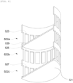
FIG. 5 is a perspective view showing the inside of the mixed gas flow pipe according to an embodiment of the present disclosure. -
FIG. 6 is a perspective view showing the inside of a mixed gas flow pipe according to another embodiment of the present disclosure. - Various advantages and features of the present disclosure and methods for accomplishing the same will become apparent to the skilled person of the art from the embodiments and examples described in detail below. However, it is noted that the present disclosure is not limited only to the embodiments and examples disclosed below, and may be implemented in various different forms. These embodiments and examples are provided only for making the present disclosure complete and for allowing those skilled in the art to fully appreciate the scope of the present disclosure as defined by the claims.
- Unless defined otherwise, all terms (including technical and scientific terms) used in the specification have the same meanings as meanings commonly understood by those skilled in the art to which the present disclosure pertains.
- Terms of a singular number used in the specification may be interpreted as including its plural number unless otherwise indicated.
- A numerical range used in the specification may include the lower and upper limits and all values within that range, increments logically derived from the shape and width of the defined range, all values delimited by those limits, and all possible combinations of the upper and lower limits of a numerical range delimited by different shapes. The defined numerical range may also include values outside the numerical range, which may occur due to experimental errors or rounding of values unless otherwise specified in the specification.
- A term "to include" or "to comprise" in the specification is a comprehensive description that has the meaning equivalent to an expression such as "to include", "to comprise", "to contain", "to have", or "to be featured", and does not exclude an element, a material, or a process that is not additionally enumerated.
- The terms "upper", "middle" and "lower" generally means a spatial distribution in a longitudinal direction of the system; these terms may refer to a separation of the corresponding element in a direction of stream (downstream or upstream), regardless whether a system having a certain longitudinal shape is arranged in an upward/vertical orientation or in a horizontal orientation.
- Unless otherwise indicated, a unit of % used in the specification may indicate % by weight.
- In the specification, "A to B" indicates "A or more and B or less" unless otherwise specifically defined.
- An embodiment of the present disclosure may provide a mixed gas distribution system including a gas distribution device; a mixed gas supply line connected to the gas distribution device; a flow induction guide; an upper area; and a plurality of mixed gas flow pipes fixed to a circumference part of a bottom surface of the upper area, and connected to a plurality of openings formed in the circumference part of the bottom surface to enable a movement of mixed gas, wherein the gas distribution device is installed horizontally, a plurality of mixed gas distribution openings are formed in an outer surface of the gas distribution device and distribute the mixed gas, the upper area has the bottom surface and a side surface connecting the bottom surface with an upper wall inside an ammonia synthesis reactor, a circular opening is formed in the center of the bottom surface of the upper area, the flow induction guide has a side surface connecting an upper circumference of an inner drum included in the reactor with a circumference of the circular opening formed in the center of the bottom surface of the upper area, a fixation bracket is disposed on an inner surface of the flow induction guide, and the gas distribution device is supported by the fixation bracket.
- The mixed gas distribution system and an ammonia synthesis system comprising the mixed gas distribution system according to an embodiment of the present disclosure may maintain a uniform flow rate distribution upstream of a catalyst bed included in the ammonia synthesis reactor even when a flow rate of a raw material, such as hydrogen, fed into the ammonia synthesis system is decreased.
- In addition, the mixed gas distribution system and the ammonia synthesis system according to an embodiment of the present disclosure may achieve excellent mixing efficiency of hydrogen and nitrogen, which are the raw materials for synthesizing ammonia.
- Referring to
FIGS. 1 and3 , the mixed gas distribution system according to an embodiment of the present disclosure may include agas distribution device 1; a mixedgas supply line 2 connected to thegas distribution device 1; aflow induction guide 3; anupper area 4; and a plurality of mixedgas flow pipes 5 fixed to a circumference part of abottom surface 401 of theupper area 4, and connected to a plurality ofopenings 407 formed in the circumference part of thebottom surface 401 to enable the movement of the mixed gas. Each of the plurality ofopenings 407 may (optionally) correlate with the mixedgas flow pipe 5 located respectively below each opening 407 for gas flow. - The
gas distribution device 1 may be installed horizontally, and a plurality of mixedgas distribution openings 101 for distributing the mixed gas may be formed in an outer surface of thegas distribution device 1. The mixed gas, supplied through the mixedgas supply line 2, may be distributed into the ammonia synthesis reactor through the mixedgas distribution openings 101. Thegas distribution device 1 may uniformly mix the mixed gas flowing in from aninner drum 7 with the mixed gas supplied from the mixedgas supply line 2. - The mixed
gas distribution openings 101 may distribute the mixed gas upward or downward, however, the embodiments are not be limited in this way. The mixed gas distribution openings are spaced apart from each other and may be arranged in any suitable pattern. - Referring to
FIG. 3 , theupper area 4 may have thebottom surface 401 and aside surface 403 connecting thebottom surface 401 with the upper wall inside the reactor, and acircular opening 405 may be formed in the center of thebottom surface 401 of theupper area 4. The mixed gas introduced from theinner drum 7 and the mixed gas supplied from the mixedgas supply line 2 may flow into theupper area 4 through theflow induction guide 3 and may then be directed toward the side surface of theupper area 4 and pass through the plurality ofopenings 407 to thus flow into the plurality of mixedgas flow pipes 5. - The
flow induction guide 3 may have aside surface 301 connecting an upper circumference of theinner drum 7 included in the reactor with the circumference of thecircular opening 405 formed in the center of thebottom surface 401 of theupper area 4. Theflow induction guide 3 may include afixation bracket 303 disposed on an inner surface of theflow induction guide 3 for supporting thegas distribution device 1. The mixed gas flowing in from theinner drum 7 and the mixed gas supplied from the mixedgas supply line 2 may flow into theupper area 4 along theflow induction guide 3. - The
gas distribution device 1 may be supported by thefixation bracket 303. Thefixation bracket 303 is configured to provide support for the gas distribution device creating a ring-shape support structure along the internal circumference of theflow induction guide 3. The ring shapedfixation bracket 303 may have a small width to leave most of the cross-sectional area of theflow induction guide 3 open for the mixed gas flow to pass through unobstructed and reach the mixedgas distribution device 1. The mixed gas flow may then flow through the mixedgas distribution openings 101 toward theupper area 4 of the mixed gas distribution system. The mixed gas may then pass through the plurality ofopenings 407 of thebottom surface 401 of theupper area 4 into the mixedgas flow pipes 5. - A
distribution plate 8 may be installed horizontally above an upper surface of theinner drum 7. For example, thedistribution plate 8 may be installed on the upper surface of theinner drum 7. Thedistribution plate 8 may include a plurality ofopenings 8a. Through theopenings 8a of thedistribution plate 8, the mixed gas may uniformly flow in from theinner drum 7 to theflow induction guide 3 of the mixed gas distribution system. - Referring to
FIGS. 3 to 5 , each of the mixedgas flow pipes 5 may have abottom surface 521 and a side surface 522 (522a, 522b, 522c) connecting thebottom surface 521 with thecorresponding opening 407 formed in the circumference part of the bottom surface of theupper area 4. Thebottom surface 521 of the mixed gas flow pipe may be a plate without any openings. - A plurality of
upper openings 523 may be formed in a side surface of anupper part 522a of the mixedgas flow pipe 5 spaced apart from each other along a circumference of thepipe 5. A plurality ofmiddle openings 525 may be formed in a side surface of amiddle part 522b of the mixedgas flow pipe 5 spaced apart from each other along the circumference of themiddle part 522b of the mixedgas flow pipe 5. A plurality oflower openings 527 may be formed in a side surface of alower part 522c of the mixedgas flow pipe 5 spaced apart from each other along the circumference of thelower part 522c of the mixedgas flow pipe 5. A flow of the mixed gas may be formed through theupper openings 523, themiddle openings 525, and thelower openings 527. The mixedgas flow pipe 5 may include acover 530 surrounding at least some regions of the side surface of the mixedgas flow pipe 5 to provide a space for a fluid flowing out of the side surface of the mixedgas flow pipe 5 after passing through theupper openings 523 to be guided toward themiddle openings 525. Thecover 530 may surround at least one selected from the group consisting of the upper and middle parts of the side surface of the mixedgas flow pipe 5. - The
cover 530 may cause the fluid flowing out of the side surface of the mixedgas flow pipe 5 after passing through theupper openings 523 to be guided toward themiddle openings 525. This configuration may form a flow in which the fluid is moved to the outside of the side surface of the mixedgas flow pipe 5 and then moved back to the inside of the side surface. Through this meander-shaped flow path, the fluids may be mixed more effectively and smoothly with each other. Better mixing is highly beneficial because it can increase the reaction rate and overall business efficiency. Better mixing can also improve catalyst utilization and reduce catalyst hot spots. - Referring to
FIG. 6 , the mixedgas flow pipe 5 may further include aseparator plate 529 dividing the upper and middle parts of the mixedgas flow pipe 5 from each other. Theseparator plate 529 may completely separate the upper and middle parts of the mixedgas flow pipe 5 from each other to prevent the movement of the fluid. More specifically, the separator plate forces the fluid flow of the mixed gas which enters a mixedgas flow pipe 5 to exit the upper part of the mixedgas flow pipe 5 through theupper openings 523 into the side space created by thecover 530 and then back into the middle part of the mixedgas flow pipe 5 through themiddle openings 525. Therefore, the fluid flowing into the upper part of the mixedgas flow pipe 5 may flow out through theupper openings 523 into the space between the mixedgas flow pipe 5 and thecover 530 rather than descending directly to the middle part, by theseparator plate 529. The fluid in the space may then flow into the mixed gas flow pipe through themiddle openings 525, descend downwards, and flow out of the mixedgas flow pipe 5 through thelower openings 527. The fluid in the lower part of the mixedgas flow pipe 5 may not exit via thebottom surface 521 of the mixedgas flow pipe 5 and is forced to exit via thelower openings 527. As described above, the fluid may form the flow in which the fluid flows out of the mixedgas flow pipe 5, flows back into the inside of the pipe, and flows out of the pipe again, thereby improving mixing efficiency of hydrogen and nitrogen, which are the ammonia synthesis raw materials, and maintaining the uniform flow rate distribution before the catalyst bed. Importantly, the mixing is accomplished passively in a consistent manner without any moving mechanical parts. - The side surface (522) may be divided into the side surface of the upper part (522a), the side surface of the middle part (522b), the side surface of the lower part (522c).
- In particular, the mixed
gas flow pipe 5 according to an embodiment of the present disclosure may be disposed above acatalyst bed 6. The mixedgas flow pipes 5 may be disposed above the catalyst bed, thus enabling the mixed gas passing through the mixedgas flow pipe 5 to be uniformly distributed to thecatalyst bed 6. This configuration may improve an ammonia synthesis yield and extend a lifespan of the catalyst bed. - The mixed gas distribution system according to an embodiment of the present disclosure may be used for the ammonia synthesis reactor. The mixed gas distribution system may maintain the uniform flow rate distribution before the catalyst bed included in the ammonia synthesis reactor even when the flow rate of the raw material, such as hydrogen, fed into the ammonia synthesis reactor is decreased especially when the mixed gas distribution system is included in the ammonia synthesis reactor, and may achieve excellent mixing efficiency of hydrogen and nitrogen, which are the ammonia synthesis raw materials.
- In an embodiment according to the present disclosure, the
gas distribution device 1 may have a toroidal shape. In another embodiment according to the present disclosure, thegas distribution device 1 may have a disk shape. However, it is noted that the embodiments may not be limited in this way and generally any suitable conventional gas distribution device may also be used. - In an embodiment according to the present disclosure, the mixed gas may include at least one selected from the group consisting of hydrogen and nitrogen.
- For example, hydrogen, the main raw material for the ammonia synthesis, may be produced by a water electrolyzer powered by renewable energy. One issue that needs to be addressed is that renewable energy, such as, for example, solar energy or wind energy are not constant or available at all times. Therefore, the amount of hydrogen (e.g., flow rate) provided by a process using renewable energy (e.g., solar or wind energy) may vary or fluctuate significantly and, hence, an ammonia synthesis system using such hydrogen cannot be operated at a constant flow rate. Such changes may have a negative impact on the overall efficiency of the ammonia synthesis system.
- In an embodiment, hydrogen may be produced by a water electrolyzer powered using renewable energy.
- Renewable energy may include at least one selected from the group consisting of solar energy, photovoltaic energy, bioenergy, wind energy, hydroelectric energy, geothermal energy, ocean energy, and waste energy. Renewable energy shows temporal variability. For example, the solar energy is unable to be used at night. Therefore, when hydrogen is produced using the device powered by renewable energy, the ammonia synthesis system is unable to be always operated at a constant flow rate. That is, there is a need for the ammonia synthesis system to cope with a change in the flow rate that occurs during a production cycle due to the temporal variability of renewable energy.
- In addition, the mixed gas supplied from the mixed
gas supply line 2 may be the cooling mixed gas having a low temperature. Therefore, the mixed gas supplied through the mixedgas supply line 2 may function as the cooling mixed gas, and may also function as a means of cooling the mixed gas flowing in the ammonia synthesis system. For example, the cooling mixed gas may be used as the cooling means to cool the mixed gas fed into the catalyst bed. - Referring to
FIG. 2 , the mixed gas distribution system according to an embodiment of the present disclosure may have aconical flow inducer 9 disposed at the center of the upper wall inside the reactor. Theconical flow inducer 9 may function as a pre-diffuser for deflecting the mixed gas for the mixed gas entering theupper area 4 to flow smoothly toward the plurality ofopenings 407, prevent a dead zone from occurring in theupper area 4, and distribute the mixed gas uniformly to the plurality of openings. - In an embodiment according to the present disclosure, the mixed
gas supply line 2 may include a flow regulating device. The flow regulating device may enable the flow rate of the mixed gas to be controlled independently in the mixedgas supply line 2. For example, the flow regulating device may independently regulate the flow rate of the mixed gas flowing through the mixedgas supply line 2 for the flow rate of the mixed gas entering the gas distribution device to be maintained within a desired flow rate range. - Through the flow regulating device, the mixed gas distribution system and the ammonia synthesis system comprising the mixed gas distribution system according to an embodiment of the present disclosure may cope with the change in the flow rate occurring during the production cycle, and maintain the uniform flow rate distribution before the catalyst bed included in the ammonia synthesis reactor even when the flow rate of a raw material feed, such as hydrogen, is decreased. The flow regulating device may be a flow regulating valve.
- Here, in the specification, the flow rate of the raw material feed (e.g., the hydrogen and nitrogen feed, also referred to as the mixed gas flow rate.) that can be changed during the production cycle may be classified into three levels, or categories for convenience. As described above, the raw material flow rate may be classified into a low flow rate, a medium flow rate, and a high flow rate. However, the change in the flow rate may be easily regulated by the common sense or judgment of those skilled in the art. The low flow rate case indicates a case where the flow rate of the mixed gas feed flow results in an ammonia produced is less than half (50%) of an annual average production flow rate (100%), the medium flow rate case indicates a case where the flow rate is half (50%) or more and less than twice (200%) of the annual average production flow rate (100%), and the high flow rate case indicates a case where the flow rate is more than twice (200%) of the annual average production flow rate (100%), but the embodiments are not limited thereto.
- The mixed
gas supply line 2 may branch from one main mixed gas supply line. Alternatively, the mixedgas supply line 2 may receive at least one gas selected from the group consisting of nitrogen and hydrogen from each of individual nitrogen and hydrogen supply lines. - In addition, the embodiments of the present disclosure may provide the ammonia synthesis system comprising the mixed gas distribution system. The same description may be applied to a content of the mixed gas distribution system overlapping a content of the ammonia synthesis system.
- An embodiment of the present disclosure may provide the ammonia synthesis system including an ammonia synthesis reactor; the mixed gas distribution system described above, which is included in the ammonia synthesis reactor; and one or
more catalyst beds 6 disposed downstream of the mixed gas distribution system. - The ammonia synthesis system according to an embodiment of the present disclosure may maintain the uniform flow rate distribution upstream of the catalyst bed or beds included in the ammonia synthesis reactor even when the flow rate of a raw material feed, such as hydrogen, is decreased.
- In addition, the ammonia synthesis system according to an embodiment of the present disclosure may achieve the excellent mixing efficiency of hydrogen and nitrogen, which are the ammonia synthesis raw materials.
- The
catalyst bed 6 may be installed in a toroidal area formed between theinner drum 7 and an outer side wall of theammonia synthesis reactor 10. The mixed gas passed through the mixedgas flow pipe 5 may flow down along the outer side wall of the ammonia synthesis reactor to reach thecatalyst bed 6. - In particular, the mixed
gas flow pipes 5 according to an embodiment of the present disclosure may be disposed above thecatalyst bed 6. The mixedgas flow pipes 5 may be disposed above the catalyst bed, thus enabling the mixed gas passed through the mixedgas flow pipes 5 to be uniformly distributed to the catalyst bed. This configuration may improve the ammonia synthesis yield and extend the lifespan of the catalyst bed. - The ammonia synthesis system according to an embodiment of the present disclosure may further include a microwave heating device. The ammonia synthesis system may further include the microwave heating device to thus enable a temperature deviation between the central and outer parts of the
catalyst bed 6 to be reduced or eliminated resulting in a uniform temperature along thecatalyst bed 6 at the beginning of its operation, thereby improving the ammonia synthesis yield. For example, the microwave heating device may enable the temperature deviation between the central and outer parts of the catalyst bed to be eliminated and the temperature may become uniform by emitting the microwaves to thecatalyst bed 6 at the beginning of the operation. In addition, the microwave heating device may improve the ammonia synthesis yield at the beginning of the operation by preheating the catalyst bed that is not sufficiently preheated at the beginning of the operation. - One or more heating devices may be installed on each catalyst bed. For example, one, two or more, three or more, four or more, five or more, ... or eight or more microwave heating devices may be installed on each catalyst bed. It is noted, however, that the number of microwave heating devices is not limited thereto. The number of the microwave heating devices may be increased based on a size of the reactor and the
catlayst beds 6 inside the reactor. Also, an installation location of the microwave heating device may be adjusted for efficient microwave emission. - The ammonia synthesis system may further include a microwave guide. There may be provided a microwave guide for each microwave device. Each microwave guide may enable the microwaves emitted by a corresponding microwave heating device to reach the catalyst bed more efficiently. The shape or installation location of the guides may be changed, amongst other considerations, based on a microwave waveform.
- In an embodiment according to the present disclosure, the number of
catalyst beds 6 may be one or more. In an embodiment according to the present disclosure, the number ofcatalyst beds 6 may be one or more, two or more, three or more, four or more, five or more, six or more, seven or more, eight or more, nine or more, ten or more, twenty or fewer, ten or fewer, nine or fewer, eight or fewer, seven or fewer, six or fewer, five or fewer, four or fewer, three or fewer, two or fewer, one or fewer, or a value between these values. - In the ammonia synthesis system according to an embodiment of the present disclosure, ammonia may be synthesized at 1 to 500 bar or 10 to 300 bar in a respective method.
- In addition, in the ammonia synthesis system according to an embodiment of the present disclosure, ammonia may be synthesized at 100 to 800°C or 200 to 700°C in a respective method.
- The ammonia synthesis system according to an embodiment of the present disclosure may further include a heat exchanger disposed downstream from the
catalyst bed 6 to remove heat from an effluent of the catalyst bed. The heat exchanger may surround the catalyst bed or its surroundings. The ammonia synthesis system according to the present disclosure may include an additional heat removal means other than the supply of the cooling the mixed gas by further including the heat exchanger. This configuration may enable the flexible operation of the ammonia synthesis system. - As set forth above, the ammonia synthesis system according to an embodiment of the present disclosure may cope with the change in the flow rate that occurs during the production cycle.
- The mixed gas distribution system and the ammonia synthesis system according to an embodiment of the present disclosure may maintain the uniform flow rate distribution before the catalyst bed included in the ammonia synthesis reactor even when the flow rate of the raw material, such as hydrogen, fed into the ammonia synthesis system is decreased.
- The mixed gas distribution system and the ammonia synthesis system according to an embodiment of the present disclosure may achieve excellent mixing efficiency of hydrogen and nitrogen, which are the raw materials for synthesizing ammonia.
- The ammonia synthesis system according to another embodiment of the present disclosure may improve the ammonia synthesis yield by enabling the temperature deviation between the central and outer parts of the catalyst bed to be eliminated and a uniform temperature to be obtained at the beginning of its operation.
- The ammonia synthesis system according to an embodiment of the present disclosure may improve the ammonia synthesis yield at the beginning of its operation by preheating the catalyst bed at the beginning of its operation.
- The ammonia synthesis system according to an embodiment of the present disclosure may synthesize ammonia in the eco-friendly manner.
- The embodiments described above are only an example to which a principle of the present disclosure is applied, and may further include other embodiments or modification of the described embodiments within the scope of the present disclosure as defined in the appended claims. Furthermore, the embodiments may be combined to form additional embodiments,
Claims (15)
- A mixed gas distribution system comprising:a gas distribution device (1);a mixed gas supply line (2) connected to the gas distribution device (1);a flow induction guide (3);an upper area (4); anda plurality of mixed gas flow pipes (5) fixed to a circumference part of a bottom surface (401) of the upper area (4), and connected to a plurality of openings (407) formed in the circumference part of the bottom surface (401) to enable a movement of mixed gas,wherein:the gas distribution device (1) is installed horizontally,a plurality of mixed gas distribution openings (101) are formed in an outer surface of the gas distribution device (1) for distributing the mixed gas,the upper area (4) has the bottom surface (401) and a side surface (403) connecting the bottom surface (401) with an upper wall inside an ammonia synthesis reactor (10),a circular opening (405) is formed in a center of the bottom surface (401) of the upper area (4),the flow induction guide (3) has a side surface (301) connecting an upper circumference of an inner drum (7) included in the reactor with a circumference of the circular opening (405) formed in the center of the bottom surface (401) of the upper area (4),a fixation bracket (303) is disposed on an inner surface of the flow induction guide (3), andthe gas distribution device (1) is supported by the fixation bracket (303).
- The system according to claim 1, wherein:the mixed gas flow pipe (5) has a bottom surface (401) and a side surface (403) connecting the bottom surface (401) with the opening (407) formed in the circumference part of the bottom surface (401) of the upper area (4),a plurality of upper openings (523) are formed in a side surface (522) of an upper part (522a) of the mixed gas flow pipe (5) spaced apart from each other along a circumference of the upper part (522a) of the mixed gas flow pipe (5),a plurality of middle openings (525) are formed in a side surface (522) of a middle part (522b) of the mixed gas flow pipe (5) spaced apart from each other along the circumference of the middle part (522b) of the mixed gas flow pipe (5),a plurality of lower openings (527) are formed in a side surface (522) of a lower part of the mixed gas flow pipe (5) spaced apart from each other along the circumference of the lower part of the mixed gas flow pipe (5), andthe mixed gas flow pipe (5) includes a cover (530) surrounding at least some regions of the side surface (522) of the mixed gas flow pipe (5) to provide a space for a fluid flowing out of the side surface (522) of the mixed gas flow pipe (5) after passing through the upper opening (523) to be guided toward the middle opening (525).
- The system according to claim 1 or 2, wherein the mixed gas flow pipe (5) further includes a separator plate (529) dividing the upper and middle parts (522b) of the mixed gas flow pipe (5) from each other.
- The system according to one of claims 1 to 3, wherein the gas distribution device (1) has a toroidal shape.
- The system according to one of claims 1 to 4, the mixed gas supply line (2) is adapted to supply cooling mixed gas.
- The system according to one of claims 1 to 5, wherein a conical flow inducer (9) is disposed at a center of the upper wall inside the reactor.
- The system according to one of claims 1 to 6, wherein the mixed gas supply line (2) includes a flow regulating device.
- The system according to one of claims 1 to 7, wherein a distribution plate (8) is installed horizontally above an upper surface of the inner drum (7).
- The system according to claim 8, wherein the distribution plate (8) includes a plurality of openings (8a) .
- An ammonia synthesis system comprising:an ammonia synthesis reactor (10);the mixed gas distribution system according to one of claims 1 to 9, which is provided in the ammonia synthesis reactor (10); andone or more catalyst beds (6) disposed downstream from the mixed gas distribution system.
- The ammonia synthesis system according to claim 10, further including a heat exchanger disposed downstream from the catalyst bed (6) in order to remove heat from an effluent of the catalyst bed.
- The ammonia synthesis system according to claim 10 or 11, further including a heat exchanger surrounding the catalyst bed (9) or its surroundings.
- A method for ammonia synthesis using an ammonia synthesis system according to one of claims 10 to 12.
- The method for ammonia synthesis using an ammonia synthesis system according to claim 13, wherein ammonia is synthesized in the ammonia synthesis system at 10 to 300 bar, and/or at 200 to 700°C.
- Use of a mixed gas distribution system according to one of claims 1 to 9 in an ammonia synthesis reactor (10).
Applications Claiming Priority (1)
| Application Number | Priority Date | Filing Date | Title |
|---|---|---|---|
| KR1020230175326A KR20250086050A (en) | 2023-12-06 | 2023-12-06 | Mixed gas distribution system and ammonia synthesis system comprising the mixed gas distribution system |
Publications (2)
| Publication Number | Publication Date |
|---|---|
| EP4566703A1 true EP4566703A1 (en) | 2025-06-11 |
| EP4566703B1 EP4566703B1 (en) | 2026-04-01 |
Family
ID=93841137
Family Applications (1)
| Application Number | Title | Priority Date | Filing Date |
|---|---|---|---|
| EP24217667.5A Active EP4566703B1 (en) | 2023-12-06 | 2024-12-05 | Mixed gas distribution system and ammonia synthesis system comprising mixed gas distribution system |
Country Status (5)
| Country | Link |
|---|---|
| US (1) | US20250187933A1 (en) |
| EP (1) | EP4566703B1 (en) |
| KR (1) | KR20250086050A (en) |
| CN (1) | CN120097359A (en) |
| AU (1) | AU2024266839A1 (en) |
Citations (4)
| Publication number | Priority date | Publication date | Assignee | Title |
|---|---|---|---|---|
| US2384874A (en) * | 1941-05-02 | 1945-09-18 | Standard Catalytic Co | Hydrocarbon synthesis reaction |
| US4230669A (en) * | 1978-07-17 | 1980-10-28 | Pullman Incorporated | Radial ammonia converter |
| CN203440099U (en) * | 2013-08-27 | 2014-02-19 | 中国石油天然气股份有限公司 | Gas mixing distributor and ammonia synthesis reactor |
| WO2022194513A1 (en) * | 2021-03-16 | 2022-09-22 | Casale Sa | Reactor system for mixing operation at partial load |
-
2023
- 2023-12-06 KR KR1020230175326A patent/KR20250086050A/en active Pending
-
2024
- 2024-10-23 US US18/923,680 patent/US20250187933A1/en active Pending
- 2024-11-25 AU AU2024266839A patent/AU2024266839A1/en active Pending
- 2024-12-03 CN CN202411760222.3A patent/CN120097359A/en active Pending
- 2024-12-05 EP EP24217667.5A patent/EP4566703B1/en active Active
Patent Citations (4)
| Publication number | Priority date | Publication date | Assignee | Title |
|---|---|---|---|---|
| US2384874A (en) * | 1941-05-02 | 1945-09-18 | Standard Catalytic Co | Hydrocarbon synthesis reaction |
| US4230669A (en) * | 1978-07-17 | 1980-10-28 | Pullman Incorporated | Radial ammonia converter |
| CN203440099U (en) * | 2013-08-27 | 2014-02-19 | 中国石油天然气股份有限公司 | Gas mixing distributor and ammonia synthesis reactor |
| WO2022194513A1 (en) * | 2021-03-16 | 2022-09-22 | Casale Sa | Reactor system for mixing operation at partial load |
Also Published As
| Publication number | Publication date |
|---|---|
| EP4566703B1 (en) | 2026-04-01 |
| KR20250086050A (en) | 2025-06-13 |
| US20250187933A1 (en) | 2025-06-12 |
| CN120097359A (en) | 2025-06-06 |
| AU2024266839A1 (en) | 2025-06-26 |
Similar Documents
| Publication | Publication Date | Title |
|---|---|---|
| JP2024514031A (en) | Reactor system for mixing operation at partial load | |
| EP4566703B1 (en) | Mixed gas distribution system and ammonia synthesis system comprising mixed gas distribution system | |
| EP4566992A1 (en) | Ammonia synthesis system and method using the same | |
| EP4566991A1 (en) | Ammonia synthesis system | |
| EP4566705A1 (en) | Gas distribution system and ammonia synthesis system using the same | |
| US20250206628A1 (en) | Ammonia synthesis system including catalyst bed containing microwave reactive catalyst mixture | |
| EP4574765A1 (en) | Ammonia synthesis system and method using the same | |
| US20250187934A1 (en) | Mixed gas distribution plate for ammonia synthesis reactor and ammonia synthesis system including the same | |
| US20250256974A1 (en) | Ammonia synthesis system and its operation method | |
| US20250236529A1 (en) | Ammonia synthesis system and its operation method | |
| KR20250086020A (en) | Mixed gas distribution plate for ammonia synthesis reactor and ammonia synthesis system including the same | |
| KR20250098792A (en) | Ammonia synthesis system | |
| US20250223180A1 (en) | Ammonia synthesis system and operation method thereof | |
| KR20250086047A (en) | Ammonia synthesis system | |
| CN203183981U (en) | Light hydrocarbon reforming reaction feeding device | |
| KR20250108468A (en) | Ammonia synthesis system and operation method thereof | |
| KR20210097987A (en) | Biological methanation reactor using multiple distributor |
Legal Events
| Date | Code | Title | Description |
|---|---|---|---|
| PUAI | Public reference made under article 153(3) epc to a published international application that has entered the european phase |
Free format text: ORIGINAL CODE: 0009012 |
|
| STAA | Information on the status of an ep patent application or granted ep patent |
Free format text: STATUS: REQUEST FOR EXAMINATION WAS MADE |
|
| 17P | Request for examination filed |
Effective date: 20241205 |
|
| AK | Designated contracting states |
Kind code of ref document: A1 Designated state(s): AL AT BE BG CH CY CZ DE DK EE ES FI FR GB GR HR HU IE IS IT LI LT LU LV MC ME MK MT NL NO PL PT RO RS SE SI SK SM TR |
|
| GRAP | Despatch of communication of intention to grant a patent |
Free format text: ORIGINAL CODE: EPIDOSNIGR1 |
|
| STAA | Information on the status of an ep patent application or granted ep patent |
Free format text: STATUS: GRANT OF PATENT IS INTENDED |
|
| INTG | Intention to grant announced |
Effective date: 20251118 |
|
| GRAS | Grant fee paid |
Free format text: ORIGINAL CODE: EPIDOSNIGR3 |
|
| GRAA | (expected) grant |
Free format text: ORIGINAL CODE: 0009210 |
|
| STAA | Information on the status of an ep patent application or granted ep patent |
Free format text: STATUS: THE PATENT HAS BEEN GRANTED |
|
| AK | Designated contracting states |
Kind code of ref document: B1 Designated state(s): AL AT BE BG CH CY CZ DE DK EE ES FI FR GB GR HR HU IE IS IT LI LT LU LV MC ME MK MT NL NO PL PT RO RS SE SI SK SM TR |
|
| REG | Reference to a national code |
Ref country code: CH Ref legal event code: F10 Free format text: ST27 STATUS EVENT CODE: U-0-0-F10-F00 (AS PROVIDED BY THE NATIONAL OFFICE) Effective date: 20260401 Ref country code: GB Ref legal event code: FG4D |
|
| REG | Reference to a national code |
Ref country code: DE Ref legal event code: R096 Ref document number: 602024003647 Country of ref document: DE |
|
| REG | Reference to a national code |
Ref country code: IE Ref legal event code: FG4D |
|
| REG | Reference to a national code |
Ref country code: NL Ref legal event code: MP Effective date: 20260401 |