EP4566507A1 - Dishwasher - Google Patents
Dishwasher Download PDFInfo
- Publication number
- EP4566507A1 EP4566507A1 EP23855055.2A EP23855055A EP4566507A1 EP 4566507 A1 EP4566507 A1 EP 4566507A1 EP 23855055 A EP23855055 A EP 23855055A EP 4566507 A1 EP4566507 A1 EP 4566507A1
- Authority
- EP
- European Patent Office
- Prior art keywords
- turbidity
- washing
- washing water
- cycle
- dishwasher
- Prior art date
- Legal status (The legal status is an assumption and is not a legal conclusion. Google has not performed a legal analysis and makes no representation as to the accuracy of the status listed.)
- Pending
Links
Images




Classifications
-
- A—HUMAN NECESSITIES
- A47—FURNITURE; DOMESTIC ARTICLES OR APPLIANCES; COFFEE MILLS; SPICE MILLS; SUCTION CLEANERS IN GENERAL
- A47L—DOMESTIC WASHING OR CLEANING; SUCTION CLEANERS IN GENERAL
- A47L15/00—Washing or rinsing machines for crockery or tableware
- A47L15/42—Details
- A47L15/4297—Arrangements for detecting or measuring the condition of the washing water, e.g. turbidity
-
- A—HUMAN NECESSITIES
- A47—FURNITURE; DOMESTIC ARTICLES OR APPLIANCES; COFFEE MILLS; SPICE MILLS; SUCTION CLEANERS IN GENERAL
- A47L—DOMESTIC WASHING OR CLEANING; SUCTION CLEANERS IN GENERAL
- A47L15/00—Washing or rinsing machines for crockery or tableware
- A47L15/0018—Controlling processes, i.e. processes to control the operation of the machine characterised by the purpose or target of the control
- A47L15/0021—Regulation of operational steps within the washing processes, e.g. optimisation or improvement of operational steps depending from the detergent nature or from the condition of the crockery
-
- A—HUMAN NECESSITIES
- A47—FURNITURE; DOMESTIC ARTICLES OR APPLIANCES; COFFEE MILLS; SPICE MILLS; SUCTION CLEANERS IN GENERAL
- A47L—DOMESTIC WASHING OR CLEANING; SUCTION CLEANERS IN GENERAL
- A47L15/00—Washing or rinsing machines for crockery or tableware
- A47L15/0018—Controlling processes, i.e. processes to control the operation of the machine characterised by the purpose or target of the control
- A47L15/0021—Regulation of operational steps within the washing processes, e.g. optimisation or improvement of operational steps depending from the detergent nature or from the condition of the crockery
- A47L15/0026—Rinsing phases
-
- A—HUMAN NECESSITIES
- A47—FURNITURE; DOMESTIC ARTICLES OR APPLIANCES; COFFEE MILLS; SPICE MILLS; SUCTION CLEANERS IN GENERAL
- A47L—DOMESTIC WASHING OR CLEANING; SUCTION CLEANERS IN GENERAL
- A47L15/00—Washing or rinsing machines for crockery or tableware
- A47L15/0018—Controlling processes, i.e. processes to control the operation of the machine characterised by the purpose or target of the control
- A47L15/0021—Regulation of operational steps within the washing processes, e.g. optimisation or improvement of operational steps depending from the detergent nature or from the condition of the crockery
- A47L15/0028—Washing phases
-
- A—HUMAN NECESSITIES
- A47—FURNITURE; DOMESTIC ARTICLES OR APPLIANCES; COFFEE MILLS; SPICE MILLS; SUCTION CLEANERS IN GENERAL
- A47L—DOMESTIC WASHING OR CLEANING; SUCTION CLEANERS IN GENERAL
- A47L15/00—Washing or rinsing machines for crockery or tableware
- A47L15/0018—Controlling processes, i.e. processes to control the operation of the machine characterised by the purpose or target of the control
- A47L15/0047—Energy or water consumption, e.g. by saving energy or water
-
- A—HUMAN NECESSITIES
- A47—FURNITURE; DOMESTIC ARTICLES OR APPLIANCES; COFFEE MILLS; SPICE MILLS; SUCTION CLEANERS IN GENERAL
- A47L—DOMESTIC WASHING OR CLEANING; SUCTION CLEANERS IN GENERAL
- A47L2401/00—Automatic detection in controlling methods of washing or rinsing machines for crockery or tableware, e.g. information provided by sensors entered into controlling devices
- A47L2401/10—Water cloudiness or dirtiness, e.g. turbidity, foaming or level of bacteria
-
- A—HUMAN NECESSITIES
- A47—FURNITURE; DOMESTIC ARTICLES OR APPLIANCES; COFFEE MILLS; SPICE MILLS; SUCTION CLEANERS IN GENERAL
- A47L—DOMESTIC WASHING OR CLEANING; SUCTION CLEANERS IN GENERAL
- A47L2501/00—Output in controlling method of washing or rinsing machines for crockery or tableware, i.e. quantities or components controlled, or actions performed by the controlling device executing the controlling method
- A47L2501/05—Drain or recirculation pump, e.g. regulation of the pump rotational speed or flow direction
-
- A—HUMAN NECESSITIES
- A47—FURNITURE; DOMESTIC ARTICLES OR APPLIANCES; COFFEE MILLS; SPICE MILLS; SUCTION CLEANERS IN GENERAL
- A47L—DOMESTIC WASHING OR CLEANING; SUCTION CLEANERS IN GENERAL
- A47L2501/00—Output in controlling method of washing or rinsing machines for crockery or tableware, i.e. quantities or components controlled, or actions performed by the controlling device executing the controlling method
- A47L2501/30—Regulation of machine operational steps within the washing process, e.g. performing an additional rinsing phase, shortening or stopping of the drying phase, washing at decreased noise operation conditions
Definitions
- the present disclosure relates to a dishwasher, and more specifically, to a dishwasher that may sense turbidity of washing water in real time regardless of specific measurement conditions, thereby effectively identifying a progress of a cycle and identifying the progress of the cycle in real time via a turbidity sensor.
- a dishwasher is an apparatus that washes dishes, cooking utensils, and the like, which are washing targets, stored therein by spraying washing water like water.
- washing water used for the washing may contain detergent.
- the dishwasher is generally composed of a washing tub that defines a washing space, a dish rack that accommodates the washing targets inside the washing tub, a spraying arm that sprays washing water to the dish rack, and a sump that stores water therein and supplies washing water to the spraying arm.
- European Patent No. 2175766 (Prior Document 001) describes a configuration for measuring the turbidity via the turbidity sensor during the cycle of the dishwasher.
- Prior Document 001 describes a configuration for measuring the turbidity at a specific washing water motor speed during the cycle, a configuration for measuring the turbidity when a specific spraying arm of an upper spraying arm and a lower spraying arm rotates, and a configuration for measuring the turbidity when all of the spraying arms rotate, to reduce noise included in a turbidity value sensed via the turbidity sensor and minimize a deviation of the sensed turbidity values.
- the turbidity may be sensed only under specific conditions during the cycle and the dishwasher may be controlled via the sensed turbidity.
- the washing cycle or the rinsing cycle may proceed regardless of a contamination level and a degree of rinsing of the washing target, which causes unnecessary power loss and a high possibility of cycle time delay.
- the present disclosure is designed to solve the problems of the prior art described above, and has a first purpose of providing a dishwasher that may sense turbidity of washing water in real time regardless of specific measurement conditions, and thus, may effectively identify a progress of a cycle.
- the present disclosure has a second purpose of providing a dishwasher that may identify a progress of a cycle in real time via a turbidity sensor, and thus, may automatically increase or decrease a cycle time effectively.
- the present disclosure has a third purpose of providing a dishwasher that may complete a cycle before a planned cycle time elapses when it is identified, via detected turbidity, that washing or rinsing has progressed to a satisfactory level, and thus, minimize power loss and effectively prevent time delay.
- a dishwasher includes a tub defining a washing space therein, a sump disposed under the tub and constructed to store washing water to be supplied to the tub therein, a washing water pump that pressurizes the washing water and supplies the pressurized washing water to the washing space, a turbidity sensor that senses turbidity values of the washing water, and a controller electrically connected to the turbidity sensor and the washing water pump, and the controller detects the turbidity values of the washing water via the turbidity sensor during a cycle and determines whether to continue the cycle based on the detected turbidity values.
- controller that determines whether to continue the cycle may further calculate a rate of change of turbidity values during a washing cycle and determine whether to continue the washing cycle based on the calculated rate of change.
- the controller that determines whether to continue the washing cycle may further receive an output signal from the turbidity sensor and detect turbidity values of the washing water after operation of the washing water pump is initiated, sample the detected turbidity values of the washing water at a first interval and store the sampled turbidity values, calculate an average value of the turbidity values sampled for a first time period and stored to calculate a first turbidity average value, sample turbidity values of the washing water detected after calculating the first turbidity average value at a second interval and store the sampled turbidity values, calculate an average value of the turbidity values sampled for a second time period after calculating the first turbidity average value to calculate a second turbidity average value, and calculate a rate of change of the second turbidity average value compared to the first turbidity average value and determine whether the calculated rate of change exceeds a reference rate of change.
- controller may further determine to stop the washing cycle when the calculated rate of change is determined to be smaller than or equal to the reference rate of change.
- controller may further stop the operation of the washing water pump when the stopping of the washing cycle is determined.
- first interval and the second interval may be equal to each other.
- first interval and the second interval may be 1 second.
- the first time period and the second time period may be equal to each other.
- the reference rate of change may be 10%.
- controller that determines whether to continue the cycle may further determine whether to continue a rinsing cycle based on turbidity values measured during the rinsing cycle.
- the controller that determines whether to continue the rinsing cycle may further receive an output signal from the turbidity sensor and detect turbidity values of the washing water, sample the detected turbidity values of the washing water at a third interval and store the sampled turbidity values, and determine whether the sampled turbidity values exceed a reference turbidity value.
- controller may further determine to stop the rinsing cycle when the sampled turbidity values are determined to be smaller than the reference turbidity value.
- controller may further stop operation of the washing water pump when the stopping of the rinsing cycle is determined.
- the third interval may be 1 second.
- the reference turbidity value may be 100 NTU.
- the dishwasher according to the present disclosure may sense the turbidity of washing water in real time regardless of the specific measurement conditions, and thus, may effectively identify the progress of the cycle.
- the dishwasher according to the present disclosure may identify the progress of the cycle in real time via the turbidity sensor, and thus, may automatically increase or decrease the cycle time effectively.
- first element or layer when a first element or layer is referred to as being present "on" a second element or layer, the first element may be disposed directly on the second element or may be disposed indirectly on the second element with a third element or layer being disposed between the first and second elements or layers. It will also be understood that when a first element or layer is referred to as being present "under” a second element or layer, the first element may be disposed directly under the second element or may be disposed indirectly under the second element with a third element or layer being disposed between the first and second elements or layers.
- spatially relative terms such as “beneath,” “below,” “lower,” “under,” “above,” “upper,” and the like, may be used herein for ease of explanation to describe one element or feature's relationship to another element or feature as illustrated in the figures. It will be understood that the spatially relative terms are intended to encompass different orientations of the device in use or in operation, in addition to the orientation depicted in the figures. For example, when the device in the drawings may be turned over, elements described as “below” or “beneath” or “under” other elements or features would then be oriented “above” the other elements or features. Thus, the example terms “below” and “under” may encompass both an orientation of above and below. The device may be otherwise oriented for example, rotated 90 degrees or at other orientations, and the spatially relative descriptors used herein should be interpreted accordingly.
- a and/or B means A, B or A and B, unless specifically stated otherwise. Expression such as “at least one of” when preceding a list of elements may modify the entirety of list of elements and may not modify the individual elements of the list.
- C to D means C inclusive to D inclusive unless otherwise specified.
- FIG. 1 is a front perspective view showing a dishwasher according to the present disclosure
- FIG. 2 is a simplified cross-sectional view briefly showing an internal structure of a dishwasher according to the present disclosure.
- the dishwasher 1 may include a casing 10 that constitutes an exterior appearance, a tub 20 installed in the casing 10 and having a washing space 21 defined therein where a washing target is washed, wherein a front surface of the tub is open, a door 30 that opens/closes the open front surface of the tub 20, a driver 40 located under the tub 20 to supply, collect, circulate, and discharge washing water for washing the washing target, a dish rack 50 removably provided in the inner washing space 21 of the tub 20 to receive therein the washing target, and a water sprayer 60 installed adjacent to the dish rack 50 to spray washing water for washing the washing target thereto.
- the washing target received in the dish rack 50 may be, for example, dishes such as bowls, plates, spoons, and chopsticks, and other cooking utensils.
- the washing target will be referred to as a dish.
- the tub 20 may be formed in a box shape with an entirely open front surface, and have a configuration of a so-referred to as washing tub disposed on a base 90.
- the washing space 21 may be defined inside the tub 20.
- the open front surface of the tub 20 may be opened/closing by the door 30.
- the tub 20 may be formed via pressing of a metal plate resistant to high temperature and moisture, for example, a stainless steel plate.
- a plurality of brackets may be disposed for the purpose of supporting and installing functional components such as the dish rack 50 and the water sprayer 60 which will be described later thereon within the tub 20.
- the driver 40 may include a sump 41 that stores therein washing water, a sump cover 42 that distinguishes the sump 41 from the tub 20, a water supply 43 that supplies washing water from an external source to the sump 41, a water discharger 44 that discharges washing water of the sump 41 to an outside, a washing water pump 45 and a supply flow path 46 that supply washing water of the sump 41 to the water sprayer 60, and a filter 47 that is disposed inside the sump 41 and filters washing water.
- the water supply 43 may include a water supply pipe 431 that receives washing water from an external water source, and a water supply valve 432 that opens and closes the water supply pipe 431.
- the water discharger 44 may include a water discharge pipe 441 that has one end fluidly connected to the sump and the other end extending to the outside of the dishwasher 1, and a water discharge valve 442 that opens and closes the water discharge pipe.
- the water discharger 44 may further include a water discharge pump (not shown) for forcibly draining washing water to the outside during a washing cycle or a rinsing cycle.
- the sump cover 42 may be disposed at a top of the sump 41 and may serve to distinguish the tub 20 and the sump 41 from each other. Moreover, the sump cover 42 may have a plurality of collecting holes defined therein for collecting washing water sprayed into the washing space 21 through the water sprayer 60 into the sump 41.
- washing water sprayed from the water sprayer 60 toward the dish may fall down to a bottom of the washing space 21, and may be collected again through the sump cover 42 and into the sump 41.
- the washing water pump 45 may be disposed at a side or a lower side of the sump 41 and may serve to pressurize collected washing water and re-supply pressurized washing water to the water sprayer 60.
- the washing water pump 45 may be connected to the sump 41 and the other end thereof may be connected to the supply flow path 46.
- the washing water pump 45 may be equipped with an impeller 451, a motor 453, and the like. When power is supplied to the motor 453, the impeller 451 may rotate, and thus washing water in the sump 41 may be pressurized, and then may be supplied to the water sprayer 60 through the supply flow path 46.
- the supply flow path 46 may serve to selectively supply washing water supplied from the washing water pump 45 to the water sprayer 60.
- the supply flow path 46 may include a first supply flow path 461 connected to a lower spraying arm 61, and a second supply flow path 463 connected to an upper spraying arm 62 and a top nozzle 63.
- the supply flow path 46 may be provided with a supply flow path switching valve 465 that selectively opens/closes the supply flow paths 461 and 463.
- the supply flow path switching valve 465 may be controlled so that the supply flow paths 461 and 463 are opened sequentially or simultaneously.
- the sump 41 may be equipped with a turbidity sensor 48 as a means for sensing turbidity of washing water stored inside the sump, as will be described later.
- the water sprayer 60 may be constructed to spray washing water to the dishes stored in the dish rack 50.
- the water sprayer 60 may include the lower spraying arm 61 located at a bottom of the tub 20 to spray washing water to a lower rack 51, the upper spraying arm 62 located between the lower rack 51 and an upper rack 52 to spray washing water to the lower rack 51 and the upper rack 52, and the top nozzle 63 located at a top of the tub 20 to spray washing water to a top rack 53 or the upper rack 52.
- the lower spraying arm 61 and the upper spraying arm 62 may be rotatably disposed in the washing space 21 of the tub 20 and may spray washing water toward the dish of the dish rack 50 while being rotating.
- the lower spraying arm 61 may be rotatably supported above the sump cover 42 so as to spray washing water toward the lower rack 51 while being rotating and being disposed under the lower rack 51.
- a hub 613 to which washing water is supplied from the first supply flow path 461 may be disposed under the lower spraying arm.
- the hub 613 may be rotatably supported by a lower spraying arm holder 640 connected to the sump 41.
- the upper spraying arm 62 may be rotatably supported by an upper spraying arm holder so as to spray washing water while rotating between the lower rack 51 and the upper rack 52.
- a means to divert washing water sprayed from the lower spraying arm 61 in an upward direction (U-direction) may be further disposed on a bottom surface 25 of the tub 20 to increase a washing efficiency.
- U-direction A detailed configuration of the lower spraying arm 61 of a configuration of the water sprayer 60 will be described later with reference to FIG. 3 and below.
- the dish rack 50 for storing the dish therein may be disposed in the washing space 21.
- the dish rack 50 may be constructed to extend or retract from or into the inner space of the tub 20 through the open front surface of the tub 20.
- the dish rack includes the lower rack 51 located at a lower portion of the tub 20 to accommodate therein relatively large dishes, the upper rack 52 located above the lower rack 51 to accommodate therein medium-sized dishes, and the top rack 53 located at a top level of the tub 20 and capable of storing therein small dishes, etc.
- the present disclosure is not limited thereto.
- a description will be made based on the embodiment of the dishwasher with the three dish racks 50 as shown.
- Each of the lower rack 51, the upper rack 53, and the top rack 53 may be constructed to extend or retract from or into the inner space of the tub 20 through the open front surface of the tub 20.
- guide rails may be respectively disposed on both opposing inner side surfaces constituting an inner surface of the tub 20.
- the guide rails may include an upper rail, a lower rail, a top rail, and the like.
- Wheels may be disposed on a bottom of each of the lower rack 51, the upper rack 52, and the top rack 53.
- the user may extend the lower rack 51, the upper rack 53, and the top rack 53 from the inner space of the tub 20 through the open front surface of the tub 20 and may place the dishes thereon, or easily withdraw the dishes that have been washed out thereof.
- the guide rail 54 may be embodied as a simple rail-type fixed guide rail to guide the extending or the retracting of the water sprayer 60, or a telescopic guide rail capable of guiding the extending or the retracting of the water sprayer 60 and at the same time, increasing an extension distance thereof based on the extending of the water sprayer 60.
- the door 30 is configured for opening/closing the open front surface of the tub 20 as described above.
- a hinge (not shown) around which the door 30 is closed or opened is generally disposed at a bottom of the open front surface.
- the door 30 pivots around the hinge as a pivot axis and opens.
- a handle 31 for opening the door 30 and a control panel 32 for controlling the dishwasher 1 may be disposed on an outer side surface of the door 30.
- control panel 32 may include a display 33 that visually displays information regarding a current operating status of the dishwasher 1, etc., and a button unit 34 including a selection button through which a user's course selection manipulation is input and a power button through which a user's manipulation for turning the dishwasher on and off is input.
- an inner side surface of the door 30 may form one surface of the tub 20 when the door 30 is closed, and at the same time, may form a seating surface on which the lower rack 51 of the dish rack 50 may be supported when the door 30 is fully opened.
- the inner side surface of the door 30 forms a horizontal plane in the same direction as the extension direction of the guide rail 54 that guides the lower rack 51.
- the door may further include a detergent supply for storing therein detergent to be used in a washing cycle and a rinsing agent to be used in a rinsing cycle, and automatically discharging them into the washing space 21.
- an automatic door opening module 352 for automatically opening the door may be disposed at an outer side of a top surface of the tub 20.
- the automatic door opening module 352 serves to move the door 30 to a predetermined opening position and partially open a front surface 22 of the tub 20 when a drying air supply 80 to be described later is operated and drying air is supplied into the tub 20.
- air that has become moist while drying the dishes may be discharged via an upper side of the opened front surface 22 of the tub 20.
- the automatic door opening module 352 may be equipped with a push rod 3524 that pivots and moves an upper end of a rear surface of the door 30 to the opening position.
- the drying air supply 80 for generating and supplying high-temperature or low-temperature drying air to the washing space inside the tub 20 may be disposed under the tub 20.
- the drying air supply 80 may include a filter member 883 that filters outside air, a blower fan 825 that generates a drying air flow, a heater 84 that heats the drying air flow, and an air flow guide 83 that is disposed inside the tub and guides the drying air flow.
- a drying air supply hole may be defined in a bottom surface of the tub 20 such that high-temperature drying air generated by the drying air supply may be introduced into the tub 20.
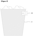
- FIG. 3 is a schematic diagram showing a state in which the turbidity sensor 48 of the dishwasher 1 according to an embodiment of the present disclosure is disposed at the sump 41
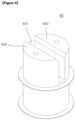
- FIG. 4 is a perspective view showing an example of the turbidity sensor 48 shown in FIG. 3 .
- the turbidity sensor 48 senses the turbidity of washing water stored in the sump 41.
- the turbidity sensor 48 may be installed through the sump 41.
- the dishwasher 1 may be equipped to proceed with the washing cycle of spraying washing water onto the dishes to wash the dishes, a rinsing cycle of spraying newly supplied washing water onto the dishes to rinse the dishes, and a drying cycle of drying the dishes using the drying air flow generated by the drying air supply 80.
- a controller 100 to be described below may receive a command on whether to continue the drying cycle.
- the washing cycle may include a preliminary washing cycle of spraying washing water not containing the detergent onto the dishes, and a detergent washing cycle of adding the detergent to washing water and spraying washing water onto the dishes.
- the rinsing cycle may include a preliminary rinsing cycle of spraying washing water not containing the rinsing agent onto the dishes, and a rinsing agent rinsing cycle off adding the rinsing agent to washing water and spraying washing water onto the dishes.
- the rinsing cycle may further include a heating rinsing cycle.
- a heating rinsing cycle When washing water is heated and used for the rinsing, the dishes may be heated, and in the drying cycle that follows, residual heat of the dishes may facilitate evaporation of water remaining on surfaces of the dishes.
- the turbidity sensor 48 may be disposed close to an upper end of the sump 41. As illustrated in FIG. 4 , the turbidity sensor 48 may include a sensing area 481 through which washing water flows, a light emitter 482 that is disposed opposite to the sensing area 481 and emits light such that light passes through the sensing area 481, and a light receiver 483 that receives light that passes through the sensing area 481.
- Washing water supplied into the sump 41 may flow along the sensing area 481 of the turbidity sensor 48.
- Light emitted from the light emitter 482 may pass through washing water flowing through the sensing area 481 and be received by the light receiver 483.
- the controller 100 may convert the voltage value included in the output signal into a turbidity value corresponding thereto using a pre-stored conversion table to calculate a current turbidity value of washing water.
- the conversion table may be separately converted into data and stored in advance in a memory.
- the controller 100 may separately store the calculated turbidity value as data in the memory.
- the turbidity values may be sampled at a predetermined interval, i.e., a 1-second interval, and stored in the memory.
- the turbidity sensor 48 may sense not only the turbidity of washing water, but also an amount of foam present in the washing space 21.
- excessive foam may be generated inside the washing space 21 because of misuse of the detergent or the like.
- the generated foam may be located on a surface of washing water stored in the sump 41. Accordingly, light output from the light emitter 482 is reflected from a surface of the foam, and only a portion of light output from the light emitter 482 is transmitted to the light receiver 483. Accordingly, when the voltage value is low, the amount of foam is determined to be great, and when the voltage value is high, the amount of foam is determined to be small. That is, the turbidity value is proportional to the amount of foam.
- the dishwasher 1 may include the controller 100 for controlling each functional component.
- the controller 100 may be in various forms such as a microcontroller, a microcomputer, or a microprocessor, as is known in the art.
- the controller 100 may be electrically connected to a power converter (not shown). Power input from an external power source that is not shown may be converted through the power converter and supplied to the controller 100, the motor 453 of the washing water pump 45, the water supply valve 432, the water discharge valve 442, the turbidity sensor 48, the supply flow path switching valve 465, and the like.
- controller 100 may be electrically connected to the water supply valve 432 that opens and closes the water supply pipe 431 receiving washing water from an external water source, and the motor 453 of the washing water pump 45 that pressurizes washing water supplied via the water supply pipe 431 and supplies pressurized washing water to the washing space 21 of the tub 20.
- the controller 100 may open the water supply valve 432 such that washing water is supplied to the sump 41 via the water supply pipe 431, and supply the power to the motor 453 of the washing water pump 45 to operate the washing water pump 45 for pressurizing washing water stored in the sump 41 and providing pressurized washing water to the water sprayer 60.
- controller 100 may be electrically connected to the supply flow path switching valve 465, which switches the flow path such that washing water pressurized via the washing water pump 45 may be distributed and supplied to the lower spraying arm 61, the upper spraying arm 62, or the top nozzle 63 constituting the water sprayer 60.
- the controller 100 may transmit a control signal to the supply flow path switching valve 465 to control an entirety or a portion of pressurized washing water to be supplied to the lower spraying arm 61 via the first supply flow path 461 or supplied to the upper spraying arm 62 and the top nozzle 63 via the second supply flow path 463.
- controller 100 may be electrically connected to the water discharge valve 442 that opens and closes the water discharge pipe 441 for discharging washing water that has completed washing or rinsing the washing target to the outside.
- the controller 100 may control the water discharge valve 442 to close the water discharge pipe 441 while the washing cycle or the rinsing cycle is in progress and to open the water discharge pipe 441 when the washing cycle or the rinsing cycle is completed.
- controller 100 may be electrically connected to the turbidity sensor 48 for sensing the turbidity of washing water in real time during the washing cycle or the rinsing cycle.
- the turbidity sensor 48 may generate the voltage value that varies based on the turbidity or the contamination level of washing water as the output signal and transmit the out signal to the controller 100 in real time.
- the controller 100 electrically connected to the turbidity sensor 48 may receive the output signal of the turbidity sensor 48, and convert the received output signal into the turbidity value to detect the current turbidity of washing water.
- the controller 100 may indirectly estimate a current washed state or rinsed state of the washing target in real time based on the detected turbidity value of washing water.
- controller 100 may determine whether to continue, i.e., whether to stop, the washing cycle or the rinsing cycle, based on the washed state or the rinsed state of the washing target estimated via the turbidity value.
- basis for determining the washed state of the washing target during the washing cycle and the rinsed state of the washing target during the rinsing cycle may be different from each other.
- FIGS. 6 and 7 show graphs that record turbidity values of washing water detected during a washing cycle over time.
- the contamination level or a degree of washing of the washing target may be estimated based on a rate of change RM of the turbidity value of washing water.
- the rate of change RM of the turbidity value detected via the turbidity sensor 48 exceeds a predetermined level, it may be determined that decontamination of the washing target is not completed, that is, the washing is not completed, and when the rate of change RM of the turbidity value is equal to or lower than the predetermined level, it may be determined that the decontamination of the washing target is sufficiently completed, that is, the washing is completed.
- Such rate of change RM of the turbidity value may be calculated via a following process as an example.
- a first turbidity average value M1 of the turbidity values sampled at a first interval for a predetermined first time period after the washing cycle is initiated and the operation of the washing water pump 45 is initiated is calculated.
- a second turbidity average value M1 of the turbidity values sampled at a second interval for a second time period after the first time period has elapsed is calculated.
- a rate of change RM of the second turbidity average value M2 with respect to the first turbidity average value is calculated, and the calculated rate of change RM is compared with a predetermined reference rate of change RMth.
- the washing is assumed to be completed and the washing cycle is ended.
- the washing is assumed to be incomplete and thus the washing cycle is continued, and the above process is repeated.
- each of the first interval and the second interval may be 1 second, and each of the first time period and the second time period may be 5 minutes.
- detection of the rate of change RM of the turbidity value and determination of the reference rate of change RMth may be performed in units of 5 minutes, and whether to stop the washing cycle may be determined in units of 5 minutes.
- the reference rate of change RMth may be 10%.
- criteria for determining the washed state of the washing target in the rinsing cycle are as follows.
- the rinsing cycle is a process for removing the detergent remaining on the washing target after the completion of the washing cycle.
- the rinsed state of the washing target may be determined by an amount of residual detergent or an amount of rinsing agent injected during the rinsing cycle, and this may be estimated via the turbidity value of washing water sensed by the turbidity sensor 48.
- Whether to stop the rinsing cycle may be determined by comparing turbidity values measured by the turbidity sensor 48 and sampled at a third interval with a reference turbidity value.
- the reference turbidity value may be 100 nephelometry turbidity unit (NTU).
- 100 NTU is a turbidity numeric value that is measured when the drainaing and rinsing processes are repeated approximately 4 times and is recognized by safety standards and.
- the controller 100 is electrically connected to the memory and a timer.
- the controller 100 calls an operating condition and a time condition for each cycle that are stored in advance in the memory and uses them to generate a control signal for controlling progress and end of the cycle.
- the conversion table for converting the output signal received from the turbidity sensor 48 into the turbidity value may be stored in advance in the memory, and the converted turbidity value may be separately converted into the data and stored in the memory.
- the controller 100 may calculate an elapsed time or the like of each cycle using the timer, and compare the elapsed time with the time condition for each cycle that is stored in advance to determine whether to complete each cycle.
- the timer may be used for time measurement of the first interval to the third interval for sampling the turbidity values and for measurement of the first time period and the second time period for calculating the turbidity average values M1 and M2.
- the controller 100 is electrically connected to the display and a sound output unit.
- the controller 100 may visually display information regarding the operating status, an operating time, whether the cycle is completed, and the like of the dishwasher 1 via the display, and may control a message regarding the operating status or the completion of the cycle of the dishwasher 1 to be output as a voice or sound via the sound output unit such as a buzzer or a speaker described above.
- the dishwasher 1 may be controlled to detect the turbidity value of washing water during the cycle (S10), and identify the progress of the cycle in real time based on the detected turbidity value and determine whether to complete the cycle based on the identified progress (S20).
- FIG. 10 shows a process of calculating a rate of change of a turbidity value during a washing cycle and determining whether to continue the washing cycle based on the calculated rate of change.
- the controller 100 opens the water supply valve 432 such that washing water is supplied to the sump 41 via the water supply pipe 431 (S101).
- the controller 100 When the water supply valve 432 is opened, the controller 100 initiates measuring a washing time Tw from the time when the water supply valve 432 is opened, via the timer (S102).
- the controller 100 supplies the power to the motor 453 of the washing water pump 45 to initiate the operation of the washing water pump 45, to supply washing water to the water sprayer 60 (S103).
- the controller 100 When the operation of the washing water pump 45 is initiated, the controller 100 operates the detergent supply to supply the detergent to the washing space 21 of the tub 20 (S104).
- step S104 may be omitted.
- the controller 100 receives the output signal from the turbidity sensor 48, calls the data for the conversion table from the memory to convert the received output signal into the turbidity value, and converts the output signal into the turbidity value using the conversion table to detect the current turbidity value of washing water (S105).
- the controller 100 samples the detected turbidity values at the first interval, and stores the sampled turbidity values in the memory (S106).
- the first interval may be 1 second, for example.
- the controller 100 calls the turbidity values sampled for the first time period from the memory, and calculates the called turbidity values to calculate the first turbidity average value M1 (S107).
- the first turbidity average value M1 calculated here may be stored in the memory, and the first time period may be 5 minutes, for example.
- the controller 100 samples the turbidity values of washing water detected after calculating the first turbidity average value M1 at the second interval, and stores the sampled turbidity values in the memory (S108).
- the second interval may be 1 second, the same as the first interval.
- the controller 100 calls, from the memory, the turbidity values sampled during the second time period after the first turbidity average value is calculated, and calculates the called turbidity values to calculate the second turbidity average value M2 (S109).
- the second turbidity average value M2 calculated here may be stored in the memory, and the second time period may be 5 minutes, the same as the first time period.
- the controller 100 calculates the rate of change RM of the second turbidity average value M2 compared to the first turbidity average value M1, and determines whether the calculated rate of change RM exceeds the reference rate of change RMth (S110).
- the rate of change RM may be calculated using the above-mentioned Mathematical Formula.
- the controller 100 determines to stop the washing cycle by assuming that the washing of the washing target has been completed, and stops the washing water pump 45 by stopping the power supply to the motor of the washing water pump 45 (S112). Accordingly, the washing cycle (S100) may be ended.
- the controller 100 determines to continue the washing cycle by assuming that the sahing of the washing target has not been completed, and determines, via the timer, whether the washing time Tw that has elapsed so far exceeds a planned washing time Tw_th (S111).
- Comparing the washing time Tw with the planned washing time Tw_th as above may have a purpose of preventing the washing cycle from being excessively delayed in case of an error or a malfunction in the turbidity sensor 48 or the like.
- the controller 100 may proceed to the aforementioned step S112 to end the washing cycle (S100).
- the controller 100 may return to the aforementioned step S105 and repeat the subsequent steps to continue the washing cycle (S100).
- FIG. 11 shows a process of detecting the turbidity value during a unit rinsing cycle (S200) and determining whether to continue the unit rinsing cycle (S200) based on the detected turbidity value.
- the unit rinsing cycle (S200) in the illustrated embodiment may be preset to be performed only once or performed a plurality of times, or an operation mode thereof may be selected by the user.
- steps performed during the unit rinsing cycle (S200) will be mainly described, and in the operation mode in which the rinsing cycle (S200) is performed a plurality of times, the process illustrated in FIG. 11 may be repeatedly performed.
- the controller 100 opens the water discharge valve 442 such that washing water that has completed the washing cycle may be drained (S201).
- the controller 100 opens the water supply valve 432 to replenish washing water such that new washing water is supplied to the sump 41 via the water supply pipe 431 (S202).
- the controller 100 When the water supply valve 432 is opened, the controller 100 initiates measuring a rinsing time Tr from the time the water supply valve 432 is opened, via the timer (S203).
- the controller 100 supplies the power to the motor 453 of the washing water pump 45 to initiate the operation of the washing water pump 45, to supply washing water to the water sprayer 60 (S204).
- the controller 100 may also proceed with a step of supplying the rinsing agent to the washing space 21 of the tub 20 by operating the detergent supply.
- the controller 100 receives the output signal from the turbidity sensor 48, calls the data for the conversion table from the memory to convert the received output signal into the turbidity value, and converts the output signal into the turbidity value using the conversion table to detect the current turbidity value of washing water (S205).
- the controller 100 samples the detected turbidity values at the third interval, and stores the sampled turbidity values in the memory (S206).
- the third interval may be 1 second, for example.
- the controller 100 determines whether the sampled turbidity value exceeds the reference turbidity value (S207).
- the reference turbidity value may be 100 NTU as described above.
- the controller 100 determines to stop the rinsing cycle by assuming that the rinsing of the washing target is completed, and stops the washing water pump by stopping the power supply to the motor of the washing water pump 45 (S209). Accordingly, the rinsing cycle (S200) may be ended.
- the controller 100 determines to continue the rinsing cycle by assuming that the rinsing of the washing target is not completed, and determines, via the timer, whether the rinsing time Tr that has elapsed so far exceeds a planned rinsing time Tr_th (S208).
- Comparing the rinsing time Tr with the planned rinsing time Tr_th as above may have a purpose of preventing the rinsing cycle from being excessively delayed in case of the error or the malfunction in the turbidity sensor 48 or the like, in the same manner as in the washing cycle (S100).
- the controller 100 may proceed to the aforementioned step S209 to end the rinsing cycle (S200).
- the controller 100 may return to the aforementioned step S204 and repeat the subsequent steps to continue the rinsing cycle (S200).
Landscapes
- Washing And Drying Of Tableware (AREA)
Abstract
Description
- The present disclosure relates to a dishwasher, and more specifically, to a dishwasher that may sense turbidity of washing water in real time regardless of specific measurement conditions, thereby effectively identifying a progress of a cycle and identifying the progress of the cycle in real time via a turbidity sensor.
- A dishwasher is an apparatus that washes dishes, cooking utensils, and the like, which are washing targets, stored therein by spraying washing water like water. In this regard, washing water used for the washing may contain detergent.
- The dishwasher is generally composed of a washing tub that defines a washing space, a dish rack that accommodates the washing targets inside the washing tub, a spraying arm that sprays washing water to the dish rack, and a sump that stores water therein and supplies washing water to the spraying arm.
- Using such a dishwasher, time and effort required to wash the washing targets such as the dishes after a meal may be reduced, contributing to convenience of a user.
- Recently, a technology for detecting turbidity of washing water using a turbidity sensor and determining a progress of a cycle based on the detected turbidity has been developed.
- In this regard,
European Patent No. 2175766 (Prior Document 001) describes a configuration for measuring the turbidity via the turbidity sensor during the cycle of the dishwasher. - More specifically, Prior Document 001 describes a configuration for measuring the turbidity at a specific washing water motor speed during the cycle, a configuration for measuring the turbidity when a specific spraying arm of an upper spraying arm and a lower spraying arm rotates, and a configuration for measuring the turbidity when all of the spraying arms rotate, to reduce noise included in a turbidity value sensed via the turbidity sensor and minimize a deviation of the sensed turbidity values.
- However, in Prior Document 001, to minimize the noise and the deviation as such, the turbidity may be sensed only under specific conditions during the cycle and the dishwasher may be controlled via the sensed turbidity.
- Therefore, even when a washing cycle or a rinsing cycle using the dishwasher is completed to a satisfactory level, a situation in which the turbidity is not sensed may occur when the conditions for detecting the turbidity are not met.
- In this case, the washing cycle or the rinsing cycle may proceed regardless of a contamination level and a degree of rinsing of the washing target, which causes unnecessary power loss and a high possibility of cycle time delay.
- The present disclosure is designed to solve the problems of the prior art described above, and has a first purpose of providing a dishwasher that may sense turbidity of washing water in real time regardless of specific measurement conditions, and thus, may effectively identify a progress of a cycle.
- In addition, the present disclosure has a second purpose of providing a dishwasher that may identify a progress of a cycle in real time via a turbidity sensor, and thus, may automatically increase or decrease a cycle time effectively.
- In addition, the present disclosure has a third purpose of providing a dishwasher that may complete a cycle before a planned cycle time elapses when it is identified, via detected turbidity, that washing or rinsing has progressed to a satisfactory level, and thus, minimize power loss and effectively prevent time delay.
- Purposes of the present disclosure are not limited to the above-mentioned purpose. Other purposes and advantages of the present disclosure that are not mentioned may be understood based on following descriptions, and may be more clearly understood based on embodiments of the present disclosure. Further, it will be easily understood that the purposes and advantages of the present disclosure may be realized using means shown in the claims and combinations thereof.
- A dishwasher according to the present disclosure includes a tub defining a washing space therein, a sump disposed under the tub and constructed to store washing water to be supplied to the tub therein, a washing water pump that pressurizes the washing water and supplies the pressurized washing water to the washing space, a turbidity sensor that senses turbidity values of the washing water, and a controller electrically connected to the turbidity sensor and the washing water pump, and the controller detects the turbidity values of the washing water via the turbidity sensor during a cycle and determines whether to continue the cycle based on the detected turbidity values.
- In addition, the controller that determines whether to continue the cycle may further calculate a rate of change of turbidity values during a washing cycle and determine whether to continue the washing cycle based on the calculated rate of change.
- In addition, the controller that determines whether to continue the washing cycle may further receive an output signal from the turbidity sensor and detect turbidity values of the washing water after operation of the washing water pump is initiated, sample the detected turbidity values of the washing water at a first interval and store the sampled turbidity values, calculate an average value of the turbidity values sampled for a first time period and stored to calculate a first turbidity average value, sample turbidity values of the washing water detected after calculating the first turbidity average value at a second interval and store the sampled turbidity values, calculate an average value of the turbidity values sampled for a second time period after calculating the first turbidity average value to calculate a second turbidity average value, and calculate a rate of change of the second turbidity average value compared to the first turbidity average value and determine whether the calculated rate of change exceeds a reference rate of change.
- In addition, the controller may further determine to stop the washing cycle when the calculated rate of change is determined to be smaller than or equal to the reference rate of change.
- In addition, the controller may further stop the operation of the washing water pump when the stopping of the washing cycle is determined.
- In addition, the first interval and the second interval may be equal to each other.
- In addition, the first interval and the second interval may be 1 second.
- In addition, in Claim 3, the first time period and the second time period may be equal to each other.
- In addition, the reference rate of change may be 10%.
- In addition, the controller that determines whether to continue the cycle may further determine whether to continue a rinsing cycle based on turbidity values measured during the rinsing cycle.
- In addition, the controller that determines whether to continue the rinsing cycle may further receive an output signal from the turbidity sensor and detect turbidity values of the washing water, sample the detected turbidity values of the washing water at a third interval and store the sampled turbidity values, and determine whether the sampled turbidity values exceed a reference turbidity value.
- In addition, the controller may further determine to stop the rinsing cycle when the sampled turbidity values are determined to be smaller than the reference turbidity value.
- In addition, the controller may further stop operation of the washing water pump when the stopping of the rinsing cycle is determined.
- In addition, the third interval may be 1 second.
- In addition, the reference turbidity value may be 100 NTU.
- The dishwasher according to the present disclosure may sense the turbidity of washing water in real time regardless of the specific measurement conditions, and thus, may effectively identify the progress of the cycle.
- In addition, the dishwasher according to the present disclosure may identify the progress of the cycle in real time via the turbidity sensor, and thus, may automatically increase or decrease the cycle time effectively.
- In addition, the dishwasher according to the present disclosure may complete the cycle before the planned cycle time elapses when it is identified, via the detected turbidity, that the washing or the rinsing has progressed to the satisfactory level, and thus, minimize the power loss and effectively prevent the time delay.
- In addition to the above-mentioned effects, the specific effects of the present disclosure as not mentioned will be described below along with the descriptions of the specific details for carrying out the present disclosure.
-
-
FIG. 1 is a front perspective view showing a dishwasher according to an embodiment of the present disclosure. -
FIG. 2 is a simplified cross-sectional view of a dishwasher shown inFIG. 1 . -
FIG. 3 is a schematic diagram for illustrating a state in which a turbidity sensor is installed at a sump and a function of the turbidity sensor. -
FIG. 4 is a perspective view of a turbidity sensor shown inFIG. 3 . -
FIG. 5 is a functional block diagram showing a configuration of a controller according to an embodiment of the present disclosure. -
FIGS. 6 and7 are graphs showing turbidity values detected during a washing cycle. -
FIG. 8 is a graph showing turbidity values detected during a rinsing cycle. -
FIGS. 9 to 11 are flowcharts for illustrating a method for controlling a dishwasher according to an embodiment of the present disclosure. - The above-mentioned purpose, features and advantages are described in detail below with reference to the attached drawings. Accordingly, a person skilled in the art in the technical field to which the present disclosure belongs will be able to easily implement the technical idea of the present disclosure. In describing the present disclosure, when it is determined that a detailed description of the known technology related to the present disclosure may unnecessarily obscure the gist of the present disclosure, the detailed description thereof is omitted. Hereinafter, preferred embodiments according to the present disclosure will be described in detail with reference to the attached drawings. In the drawings, identical reference numerals are used to indicate identical or similar components.
- It will be understood that, although the terms "first", "second", "third", and so on may be used herein to describe various elements, components, regions, layers and/or sections, these elements, components, regions, layers and/or sections should not be limited by these terms. These terms are used to distinguish one element, component, region, layer or section from another element, component, region, layer or section. Thus, a first element, component, region, layer or section described below could be termed a second element, component, region, layer or section, without departing from the spirit and scope of the present disclosure.
- The terminology used herein is directed to the purpose of describing particular embodiments only and is not intended to be limiting of the present disclosure. As used herein, the singular constitutes "a" and "an" are intended to include the plural constitutes as well, unless the context clearly indicates otherwise.
- It will also be understood that when a first element or layer is referred to as being present "on" a second element or layer, the first element may be disposed directly on the second element or may be disposed indirectly on the second element with a third element or layer being disposed between the first and second elements or layers. It will also be understood that when a first element or layer is referred to as being present "under" a second element or layer, the first element may be disposed directly under the second element or may be disposed indirectly under the second element with a third element or layer being disposed between the first and second elements or layers.
- It will be understood that when an element or layer is referred to as being "connected to", or "coupled to" another element or layer, it may be directly connected to or coupled to another element or layer, or one or more intervening elements or layers therebetween may be present. In addition, it will also be understood that when an element or layer is referred to as being "between" two elements or layers, it may be the only element or layer between the two elements or layers, or one or more intervening elements or layers therebetween may also be present.
- It will be further understood that the terms "comprise", "comprising", "include", and "including" when used in this specification, specify the presence of the stated features, integers, operations, elements, and/or components, but do not preclude the presence or addition of one or more other features, integers, operations, elements, components, and/or portions thereof. As used herein, the term "and/or" includes any and all combinations of one or more of associated listed items. Expression such as "at least one of" when preceding a list of elements may modify the entire list of elements and may not modify the individual elements of the list. In interpretation of numerical values, an error or tolerance therein may occur even when there is no explicit description thereof.
- Spatially relative terms, such as "beneath," "below," "lower," "under," "above," "upper," and the like, may be used herein for ease of explanation to describe one element or feature's relationship to another element or feature as illustrated in the figures. It will be understood that the spatially relative terms are intended to encompass different orientations of the device in use or in operation, in addition to the orientation depicted in the figures. For example, when the device in the drawings may be turned over, elements described as "below" or "beneath" or "under" other elements or features would then be oriented "above" the other elements or features. Thus, the example terms "below" and "under" may encompass both an orientation of above and below. The device may be otherwise oriented for example, rotated 90 degrees or at other orientations, and the spatially relative descriptors used herein should be interpreted accordingly.
- As used herein, "A and/or B" means A, B or A and B, unless specifically stated otherwise. Expression such as "at least one of" when preceding a list of elements may modify the entirety of list of elements and may not modify the individual elements of the list. As used herein, "C to D" means C inclusive to D inclusive unless otherwise specified.
- Hereinafter, the present disclosure will be described with reference to drawings showing a configuration of a
dishwasher 1 according to an embodiment of the present disclosure. - Hereinafter, an overall structure of the
dishwasher 1 according to an embodiment of the present disclosure will be described in detail with reference to the attached drawings. -
FIG. 1 is a front perspective view showing a dishwasher according to the present disclosure, andFIG. 2 is a simplified cross-sectional view briefly showing an internal structure of a dishwasher according to the present disclosure. - As shown in
FIGS. 1 to 2 , thedishwasher 1 according to an embodiment of the present disclosure may include acasing 10 that constitutes an exterior appearance, atub 20 installed in thecasing 10 and having awashing space 21 defined therein where a washing target is washed, wherein a front surface of the tub is open, adoor 30 that opens/closes the open front surface of thetub 20, adriver 40 located under thetub 20 to supply, collect, circulate, and discharge washing water for washing the washing target, adish rack 50 removably provided in theinner washing space 21 of thetub 20 to receive therein the washing target, and a water sprayer 60 installed adjacent to thedish rack 50 to spray washing water for washing the washing target thereto. - In this regard, the washing target received in the
dish rack 50 may be, for example, dishes such as bowls, plates, spoons, and chopsticks, and other cooking utensils. Hereinafter, unless otherwise specified, the washing target will be referred to as a dish. - The
tub 20 may be formed in a box shape with an entirely open front surface, and have a configuration of a so-referred to as washing tub disposed on abase 90. - The
washing space 21 may be defined inside thetub 20. The open front surface of thetub 20 may be opened/closing by thedoor 30. - The
tub 20 may be formed via pressing of a metal plate resistant to high temperature and moisture, for example, a stainless steel plate. - Moreover, on an inner surface of the
tub 20, a plurality of brackets may be disposed for the purpose of supporting and installing functional components such as thedish rack 50 and the water sprayer 60 which will be described later thereon within thetub 20. - In one example, the
driver 40 may include asump 41 that stores therein washing water, asump cover 42 that distinguishes thesump 41 from thetub 20, awater supply 43 that supplies washing water from an external source to thesump 41, a water discharger 44 that discharges washing water of thesump 41 to an outside, awashing water pump 45 and asupply flow path 46 that supply washing water of thesump 41 to the water sprayer 60, and afilter 47 that is disposed inside thesump 41 and filters washing water. - The
water supply 43 may include awater supply pipe 431 that receives washing water from an external water source, and awater supply valve 432 that opens and closes thewater supply pipe 431. - The water discharger 44 may include a
water discharge pipe 441 that has one end fluidly connected to the sump and the other end extending to the outside of thedishwasher 1, and awater discharge valve 442 that opens and closes the water discharge pipe. In this regard, the water discharger 44 may further include a water discharge pump (not shown) for forcibly draining washing water to the outside during a washing cycle or a rinsing cycle. - The
sump cover 42 may be disposed at a top of thesump 41 and may serve to distinguish thetub 20 and thesump 41 from each other. Moreover, thesump cover 42 may have a plurality of collecting holes defined therein for collecting washing water sprayed into thewashing space 21 through the water sprayer 60 into thesump 41. - That is, washing water sprayed from the water sprayer 60 toward the dish may fall down to a bottom of the
washing space 21, and may be collected again through thesump cover 42 and into thesump 41. - The
washing water pump 45 may be disposed at a side or a lower side of thesump 41 and may serve to pressurize collected washing water and re-supply pressurized washing water to the water sprayer 60. - One end of the
washing water pump 45 may be connected to thesump 41 and the other end thereof may be connected to thesupply flow path 46. Thewashing water pump 45 may be equipped with animpeller 451, amotor 453, and the like. When power is supplied to themotor 453, theimpeller 451 may rotate, and thus washing water in thesump 41 may be pressurized, and then may be supplied to the water sprayer 60 through thesupply flow path 46. - In one example, the
supply flow path 46 may serve to selectively supply washing water supplied from thewashing water pump 45 to the water sprayer 60. - For example, the
supply flow path 46 may include a firstsupply flow path 461 connected to alower spraying arm 61, and a second supply flow path 463 connected to anupper spraying arm 62 and atop nozzle 63. Thesupply flow path 46 may be provided with a supply flowpath switching valve 465 that selectively opens/closes thesupply flow paths 461 and 463. - In this regard, the supply flow
path switching valve 465 may be controlled so that thesupply flow paths 461 and 463 are opened sequentially or simultaneously. - In addition, the
sump 41 may be equipped with aturbidity sensor 48 as a means for sensing turbidity of washing water stored inside the sump, as will be described later. - In one example, the water sprayer 60 may be constructed to spray washing water to the dishes stored in the
dish rack 50. - More specifically, the water sprayer 60 may include the
lower spraying arm 61 located at a bottom of thetub 20 to spray washing water to alower rack 51, theupper spraying arm 62 located between thelower rack 51 and anupper rack 52 to spray washing water to thelower rack 51 and theupper rack 52, and thetop nozzle 63 located at a top of thetub 20 to spray washing water to atop rack 53 or theupper rack 52. - In particular, the
lower spraying arm 61 and theupper spraying arm 62 may be rotatably disposed in thewashing space 21 of thetub 20 and may spray washing water toward the dish of thedish rack 50 while being rotating. - The
lower spraying arm 61 may be rotatably supported above thesump cover 42 so as to spray washing water toward thelower rack 51 while being rotating and being disposed under thelower rack 51. - As shown, a
hub 613 to which washing water is supplied from the firstsupply flow path 461 may be disposed under the lower spraying arm. Thehub 613 may be rotatably supported by a lowerspraying arm holder 640 connected to thesump 41. - In addition, the
upper spraying arm 62 may be rotatably supported by an upper spraying arm holder so as to spray washing water while rotating between thelower rack 51 and theupper rack 52. - In one example, a means to divert washing water sprayed from the
lower spraying arm 61 in an upward direction (U-direction) may be further disposed on abottom surface 25 of thetub 20 to increase a washing efficiency. A detailed configuration of thelower spraying arm 61 of a configuration of the water sprayer 60 will be described later with reference toFIG. 3 and below. - In one example, the
dish rack 50 for storing the dish therein may be disposed in thewashing space 21. - The
dish rack 50 may be constructed to extend or retract from or into the inner space of thetub 20 through the open front surface of thetub 20. - For example, in
FIG. 2 , an embodiment is shown in which the dish rack includes thelower rack 51 located at a lower portion of thetub 20 to accommodate therein relatively large dishes, theupper rack 52 located above thelower rack 51 to accommodate therein medium-sized dishes, and thetop rack 53 located at a top level of thetub 20 and capable of storing therein small dishes, etc. However, the present disclosure is not limited thereto. However, hereinafter, a description will be made based on the embodiment of the dishwasher with the threedish racks 50 as shown. - Each of the
lower rack 51, theupper rack 53, and thetop rack 53 may be constructed to extend or retract from or into the inner space of thetub 20 through the open front surface of thetub 20. - To this end, guide rails (not shown) may be respectively disposed on both opposing inner side surfaces constituting an inner surface of the
tub 20. By way of example, the guide rails may include an upper rail, a lower rail, a top rail, and the like. - Wheels may be disposed on a bottom of each of the
lower rack 51, theupper rack 52, and thetop rack 53. The user may extend thelower rack 51, theupper rack 53, and thetop rack 53 from the inner space of thetub 20 through the open front surface of thetub 20 and may place the dishes thereon, or easily withdraw the dishes that have been washed out thereof. - The guide rail 54 may be embodied as a simple rail-type fixed guide rail to guide the extending or the retracting of the water sprayer 60, or a telescopic guide rail capable of guiding the extending or the retracting of the water sprayer 60 and at the same time, increasing an extension distance thereof based on the extending of the water sprayer 60.
- In one example, the
door 30 is configured for opening/closing the open front surface of thetub 20 as described above. - A hinge (not shown) around which the
door 30 is closed or opened is generally disposed at a bottom of the open front surface. Thus, thedoor 30 pivots around the hinge as a pivot axis and opens. - In this regard, a
handle 31 for opening thedoor 30 and acontrol panel 32 for controlling thedishwasher 1 may be disposed on an outer side surface of thedoor 30. - As shown, the
control panel 32 may include a display 33 that visually displays information regarding a current operating status of thedishwasher 1, etc., and abutton unit 34 including a selection button through which a user's course selection manipulation is input and a power button through which a user's manipulation for turning the dishwasher on and off is input. - In one example, an inner side surface of the
door 30 may form one surface of thetub 20 when thedoor 30 is closed, and at the same time, may form a seating surface on which thelower rack 51 of thedish rack 50 may be supported when thedoor 30 is fully opened. - To this end, it is preferable that, when the
door 30 is fully opened, the inner side surface of thedoor 30 forms a horizontal plane in the same direction as the extension direction of the guide rail 54 that guides thelower rack 51. - In one example, although not shown, the door may further include a detergent supply for storing therein detergent to be used in a washing cycle and a rinsing agent to be used in a rinsing cycle, and automatically discharging them into the
washing space 21. - As shown in
FIG. 2 , an automaticdoor opening module 352 for automatically opening the door may be disposed at an outer side of a top surface of thetub 20. - The automatic
door opening module 352 serves to move thedoor 30 to a predetermined opening position and partially open a front surface 22 of thetub 20 when a dryingair supply 80 to be described later is operated and drying air is supplied into thetub 20. - Accordingly, air that has become moist while drying the dishes may be discharged via an upper side of the opened front surface 22 of the
tub 20. - For example, the automatic
door opening module 352 may be equipped with apush rod 3524 that pivots and moves an upper end of a rear surface of thedoor 30 to the opening position. - In one example, the drying
air supply 80 for generating and supplying high-temperature or low-temperature drying air to the washing space inside thetub 20 may be disposed under thetub 20. - As illustrated, the drying
air supply 80 may include afilter member 883 that filters outside air, ablower fan 825 that generates a drying air flow, aheater 84 that heats the drying air flow, and an air flow guide 83 that is disposed inside the tub and guides the drying air flow. - A drying air supply hole may be defined in a bottom surface of the
tub 20 such that high-temperature drying air generated by the drying air supply may be introduced into thetub 20. -
FIG. 3 is a schematic diagram showing a state in which theturbidity sensor 48 of thedishwasher 1 according to an embodiment of the present disclosure is disposed at thesump 41, andFIG. 4 is a perspective view showing an example of theturbidity sensor 48 shown inFIG. 3 . - The
turbidity sensor 48 senses the turbidity of washing water stored in thesump 41. - To this end, as shown in
FIG. 3 , theturbidity sensor 48 may be installed through thesump 41. - The
dishwasher 1 according to an embodiment of the present disclosure may be equipped to proceed with the washing cycle of spraying washing water onto the dishes to wash the dishes, a rinsing cycle of spraying newly supplied washing water onto the dishes to rinse the dishes, and a drying cycle of drying the dishes using the drying air flow generated by the dryingair supply 80. - In this regard, when the
dishwasher 1 proceeds with a plastic course, acontroller 100 to be described below may receive a command on whether to continue the drying cycle. - In this regard, the washing cycle may include a preliminary washing cycle of spraying washing water not containing the detergent onto the dishes, and a detergent washing cycle of adding the detergent to washing water and spraying washing water onto the dishes.
- The rinsing cycle may include a preliminary rinsing cycle of spraying washing water not containing the rinsing agent onto the dishes, and a rinsing agent rinsing cycle off adding the rinsing agent to washing water and spraying washing water onto the dishes.
- In addition, the rinsing cycle may further include a heating rinsing cycle. When washing water is heated and used for the rinsing, the dishes may be heated, and in the drying cycle that follows, residual heat of the dishes may facilitate evaporation of water remaining on surfaces of the dishes.
- For the turbidity of washing water to be sensed while a sufficient amount of washing water to proceed with the washing cycle or the rinsing cycle is stored in the
sump 41, theturbidity sensor 48 may be disposed close to an upper end of thesump 41. As illustrated inFIG. 4 , theturbidity sensor 48 may include asensing area 481 through which washing water flows, alight emitter 482 that is disposed opposite to thesensing area 481 and emits light such that light passes through thesensing area 481, and alight receiver 483 that receives light that passes through thesensing area 481. - Washing water supplied into the
sump 41 may flow along thesensing area 481 of theturbidity sensor 48. - Light emitted from the
light emitter 482 may pass through washing water flowing through thesensing area 481 and be received by thelight receiver 483. - When light is received by the
light receiver 483, light may be converted into a predetermined voltage value and output, and as will be described below, an output signal of thelight receiver 483 may be transmitted to thecontroller 100. Thecontroller 100 may convert the voltage value included in the output signal into a turbidity value corresponding thereto using a pre-stored conversion table to calculate a current turbidity value of washing water. - The conversion table may be separately converted into data and stored in advance in a memory.
- The
controller 100 may separately store the calculated turbidity value as data in the memory. In this regard, as will be described later, the turbidity values may be sampled at a predetermined interval, i.e., a 1-second interval, and stored in the memory. - In one example, the
turbidity sensor 48 may sense not only the turbidity of washing water, but also an amount of foam present in thewashing space 21. - That is, excessive foam may be generated inside the
washing space 21 because of misuse of the detergent or the like. The generated foam may be located on a surface of washing water stored in thesump 41. Accordingly, light output from thelight emitter 482 is reflected from a surface of the foam, and only a portion of light output from thelight emitter 482 is transmitted to thelight receiver 483. Accordingly, when the voltage value is low, the amount of foam is determined to be great, and when the voltage value is high, the amount of foam is determined to be small. That is, the turbidity value is proportional to the amount of foam. - Hereinafter, referring to
FIG. 5 , a configuration of thecontroller 100 of thedishwasher 1 according to an embodiment of the present disclosure will be described. - As illustrated in
FIG. 5 , thedishwasher 1 according to an embodiment of the present disclosure may include thecontroller 100 for controlling each functional component. - The
controller 100 may be in various forms such as a microcontroller, a microcomputer, or a microprocessor, as is known in the art. - First, the
controller 100 may be electrically connected to a power converter (not shown). Power input from an external power source that is not shown may be converted through the power converter and supplied to thecontroller 100, themotor 453 of thewashing water pump 45, thewater supply valve 432, thewater discharge valve 442, theturbidity sensor 48, the supply flowpath switching valve 465, and the like. - In addition, the
controller 100 may be electrically connected to thewater supply valve 432 that opens and closes thewater supply pipe 431 receiving washing water from an external water source, and themotor 453 of thewashing water pump 45 that pressurizes washing water supplied via thewater supply pipe 431 and supplies pressurized washing water to thewashing space 21 of thetub 20. - As will be described below, when the washing cycle or the rinsing cycle is initiated, the
controller 100 may open thewater supply valve 432 such that washing water is supplied to thesump 41 via thewater supply pipe 431, and supply the power to themotor 453 of thewashing water pump 45 to operate thewashing water pump 45 for pressurizing washing water stored in thesump 41 and providing pressurized washing water to the water sprayer 60. - In addition, the
controller 100 may be electrically connected to the supply flowpath switching valve 465, which switches the flow path such that washing water pressurized via thewashing water pump 45 may be distributed and supplied to thelower spraying arm 61, theupper spraying arm 62, or thetop nozzle 63 constituting the water sprayer 60. - Therefore, the
controller 100 may transmit a control signal to the supply flowpath switching valve 465 to control an entirety or a portion of pressurized washing water to be supplied to thelower spraying arm 61 via the firstsupply flow path 461 or supplied to theupper spraying arm 62 and thetop nozzle 63 via the second supply flow path 463. - In addition, the
controller 100 may be electrically connected to thewater discharge valve 442 that opens and closes thewater discharge pipe 441 for discharging washing water that has completed washing or rinsing the washing target to the outside. - The
controller 100 may control thewater discharge valve 442 to close thewater discharge pipe 441 while the washing cycle or the rinsing cycle is in progress and to open thewater discharge pipe 441 when the washing cycle or the rinsing cycle is completed. - In addition, the
controller 100 may be electrically connected to theturbidity sensor 48 for sensing the turbidity of washing water in real time during the washing cycle or the rinsing cycle. - As described above, the
turbidity sensor 48 may generate the voltage value that varies based on the turbidity or the contamination level of washing water as the output signal and transmit the out signal to thecontroller 100 in real time. - The
controller 100 electrically connected to theturbidity sensor 48 may receive the output signal of theturbidity sensor 48, and convert the received output signal into the turbidity value to detect the current turbidity of washing water. - Therefore, the
controller 100 may indirectly estimate a current washed state or rinsed state of the washing target in real time based on the detected turbidity value of washing water. - In addition, the
controller 100 may determine whether to continue, i.e., whether to stop, the washing cycle or the rinsing cycle, based on the washed state or the rinsed state of the washing target estimated via the turbidity value. - However, basis for determining the washed state of the washing target during the washing cycle and the rinsed state of the washing target during the rinsing cycle may be different from each other.
- First, criteria for determining the washed state of the washing target during the washing cycle are as follows.
-
FIGS. 6 and7 show graphs that record turbidity values of washing water detected during a washing cycle over time. - As shown in
FIG. 6 , it may be seen that the turbidity value of washing water gradually increases over time as the washing cycle progresses while the contamination level of the washing target is considerably high. - On the other hand, as shown in
FIG. 7 , it may be seen that an amount of change in the turbidity value detected over time is relatively small when the washing cycle is performed while the contamination level of the washing target is relatively low, and the turbidity value converges to a specific turbidity value over time. - Judging from such detection results, the contamination level or a degree of washing of the washing target may be estimated based on a rate of change RM of the turbidity value of washing water.
- That is, when the rate of change RM of the turbidity value detected via the
turbidity sensor 48 exceeds a predetermined level, it may be determined that decontamination of the washing target is not completed, that is, the washing is not completed, and when the rate of change RM of the turbidity value is equal to or lower than the predetermined level, it may be determined that the decontamination of the washing target is sufficiently completed, that is, the washing is completed. - Such rate of change RM of the turbidity value may be calculated via a following process as an example.
- First, a first turbidity average value M1 of the turbidity values sampled at a first interval for a predetermined first time period after the washing cycle is initiated and the operation of the
washing water pump 45 is initiated is calculated. - Next, a second turbidity average value M1 of the turbidity values sampled at a second interval for a second time period after the first time period has elapsed is calculated.
- When the first turbidity average value M1 and the second turbidity average value M2 are calculated as such, a rate of change RM of the second turbidity average value M2 with respect to the first turbidity average value is calculated, and the calculated rate of change RM is compared with a predetermined reference rate of change RMth.
- In this regard, the rate of change RM may be calculated with a following Mathematical Formula.

- In this regard, when the calculated rate of change RM is determined to be smaller than or equal to the reference rate of change RMth, the washing is assumed to be completed and the washing cycle is ended. When the calculated rate of change RM is determined to be greater than the reference rate of change RMth, the washing is assumed to be incomplete and thus the washing cycle is continued, and the above process is repeated.
- In this regard, for example, each of the first interval and the second interval may be 1 second, and each of the first time period and the second time period may be 5 minutes.
- Therefore, detection of the rate of change RM of the turbidity value and determination of the reference rate of change RMth may be performed in units of 5 minutes, and whether to stop the washing cycle may be determined in units of 5 minutes.
- In addition, for example, the reference rate of change RMth may be 10%.
- In one example, criteria for determining the washed state of the washing target in the rinsing cycle are as follows.
- The rinsing cycle is a process for removing the detergent remaining on the washing target after the completion of the washing cycle.
- Therefore, the rinsed state of the washing target may be determined by an amount of residual detergent or an amount of rinsing agent injected during the rinsing cycle, and this may be estimated via the turbidity value of washing water sensed by the
turbidity sensor 48. - Further, as shown in
FIG. 8 , it may be seen that, when a draining process and a rinsing process (washing water spraying) are repeated during the rinsing cycle, the turbidity value of washing water tends to gradually decrease. - Whether to stop the rinsing cycle may be determined by comparing turbidity values measured by the
turbidity sensor 48 and sampled at a third interval with a reference turbidity value. - For example, the reference turbidity value may be 100 nephelometry turbidity unit (NTU).
- 100 NTU is a turbidity numeric value that is measured when the drainaing and rinsing processes are repeated approximately 4 times and is recognized by safety standards and.
- The process of determining whether to stop the washing cycle based on the rate of change RM of the turbidity value of washing water and the process of determining whether to stop the rinsing cycle based on the turbidity value of washing water as such will be described below with reference to
FIG. 10 and below. - In one example, the
controller 100 is electrically connected to the memory and a timer. Thecontroller 100 calls an operating condition and a time condition for each cycle that are stored in advance in the memory and uses them to generate a control signal for controlling progress and end of the cycle. In this regard, as described above, the conversion table for converting the output signal received from theturbidity sensor 48 into the turbidity value may be stored in advance in the memory, and the converted turbidity value may be separately converted into the data and stored in the memory. - In addition, the
controller 100 may calculate an elapsed time or the like of each cycle using the timer, and compare the elapsed time with the time condition for each cycle that is stored in advance to determine whether to complete each cycle. In addition, as will be described below, the timer may be used for time measurement of the first interval to the third interval for sampling the turbidity values and for measurement of the first time period and the second time period for calculating the turbidity average values M1 and M2. - In addition, although not shown, the
controller 100 is electrically connected to the display and a sound output unit. Thecontroller 100 may visually display information regarding the operating status, an operating time, whether the cycle is completed, and the like of thedishwasher 1 via the display, and may control a message regarding the operating status or the completion of the cycle of thedishwasher 1 to be output as a voice or sound via the sound output unit such as a buzzer or a speaker described above. - Hereinafter, a method for controlling the
dishwasher 1 according to the present disclosure will be described with reference toFIGS. 9 to 11 . - As described above, the
dishwasher 1 according to the present disclosure may be controlled to detect the turbidity value of washing water during the cycle (S10), and identify the progress of the cycle in real time based on the detected turbidity value and determine whether to complete the cycle based on the identified progress (S20). - This will be described as follows by distinguishing steps in the washing cycle and steps in the rinsing cycle from each other.
-
FIG. 10 shows a process of calculating a rate of change of a turbidity value during a washing cycle and determining whether to continue the washing cycle based on the calculated rate of change. - Referring to
FIG. 10 , to initiate a washing cycle (S100), thecontroller 100 opens thewater supply valve 432 such that washing water is supplied to thesump 41 via the water supply pipe 431 (S101). - When the
water supply valve 432 is opened, thecontroller 100 initiates measuring a washing time Tw from the time when thewater supply valve 432 is opened, via the timer (S102). - Next, when a predetermined amount of washing water is supplied to the
sump 41 via thewater supply valve 432, thecontroller 100 supplies the power to themotor 453 of thewashing water pump 45 to initiate the operation of thewashing water pump 45, to supply washing water to the water sprayer 60 (S103). - When the operation of the
washing water pump 45 is initiated, thecontroller 100 operates the detergent supply to supply the detergent to thewashing space 21 of the tub 20 (S104). - In this regard, in a case of a type in which the detergent is supplied manually, step S104 may be omitted.
- In one example, after the detergent is supplied, the
controller 100 receives the output signal from theturbidity sensor 48, calls the data for the conversion table from the memory to convert the received output signal into the turbidity value, and converts the output signal into the turbidity value using the conversion table to detect the current turbidity value of washing water (S105). - Next, the
controller 100 samples the detected turbidity values at the first interval, and stores the sampled turbidity values in the memory (S106). - In this regard, the first interval may be 1 second, for example.
- Next, the
controller 100 calls the turbidity values sampled for the first time period from the memory, and calculates the called turbidity values to calculate the first turbidity average value M1 (S107). - The first turbidity average value M1 calculated here may be stored in the memory, and the first time period may be 5 minutes, for example.
- When the first turbidity average value M1 is calculated and stored, the
controller 100 samples the turbidity values of washing water detected after calculating the first turbidity average value M1 at the second interval, and stores the sampled turbidity values in the memory (S108). - In this regard, the second interval may be 1 second, the same as the first interval.
- Next, the
controller 100 calls, from the memory, the turbidity values sampled during the second time period after the first turbidity average value is calculated, and calculates the called turbidity values to calculate the second turbidity average value M2 (S109). - The second turbidity average value M2 calculated here may be stored in the memory, and the second time period may be 5 minutes, the same as the first time period.
- When the second turbidity average value M2 is calculated, the
controller 100 calculates the rate of change RM of the second turbidity average value M2 compared to the first turbidity average value M1, and determines whether the calculated rate of change RM exceeds the reference rate of change RMth (S110). - In this regard, the rate of change RM may be calculated using the above-mentioned Mathematical Formula.
- In this regard, when the calculated rate of change RM is determined to be smaller than or equal to the reference rate of change RMth, the
controller 100 determines to stop the washing cycle by assuming that the washing of the washing target has been completed, and stops thewashing water pump 45 by stopping the power supply to the motor of the washing water pump 45 (S112). Accordingly, the washing cycle (S100) may be ended. - In one example, when the rate of change RM calculated in step S110 is determined to exceed the reference rate of change RMth, the
controller 100 determines to continue the washing cycle by assuming that the sahing of the washing target has not been completed, and determines, via the timer, whether the washing time Tw that has elapsed so far exceeds a planned washing time Tw_th (S111). - Comparing the washing time Tw with the planned washing time Tw_th as above may have a purpose of preventing the washing cycle from being excessively delayed in case of an error or a malfunction in the
turbidity sensor 48 or the like. - Therefore, when the washing time Tw reaches the planned washing time Tw_th, the
controller 100 may proceed to the aforementioned step S112 to end the washing cycle (S100). - However, when it is determined that the washing time Tw has not reached the planned washing time Tw_th, the
controller 100 may return to the aforementioned step S105 and repeat the subsequent steps to continue the washing cycle (S100). -
FIG. 11 shows a process of detecting the turbidity value during a unit rinsing cycle (S200) and determining whether to continue the unit rinsing cycle (S200) based on the detected turbidity value. The unit rinsing cycle (S200) in the illustrated embodiment may be preset to be performed only once or performed a plurality of times, or an operation mode thereof may be selected by the user. Hereinafter, steps performed during the unit rinsing cycle (S200) will be mainly described, and in the operation mode in which the rinsing cycle (S200) is performed a plurality of times, the process illustrated inFIG. 11 may be repeatedly performed. - Referring to
FIG. 11 , to initiate the rinsing cycle (S200), thecontroller 100 opens thewater discharge valve 442 such that washing water that has completed the washing cycle may be drained (S201). - When the
water discharge valve 442 is opened and washing water inside thesump 41 is discharged to the outside, thecontroller 100 opens thewater supply valve 432 to replenish washing water such that new washing water is supplied to thesump 41 via the water supply pipe 431 (S202). - When the
water supply valve 432 is opened, thecontroller 100 initiates measuring a rinsing time Tr from the time thewater supply valve 432 is opened, via the timer (S203). - Next, when a predetermined amount of washing water is supplied to the
sump 41 via thewater supply valve 432, thecontroller 100 supplies the power to themotor 453 of thewashing water pump 45 to initiate the operation of thewashing water pump 45, to supply washing water to the water sprayer 60 (S204). - Although not shown, when the operation of the
washing water pump 45 is initiated, thecontroller 100 may also proceed with a step of supplying the rinsing agent to thewashing space 21 of thetub 20 by operating the detergent supply. - In one example, after the operation of the
washing water pump 45 is initiated, thecontroller 100 receives the output signal from theturbidity sensor 48, calls the data for the conversion table from the memory to convert the received output signal into the turbidity value, and converts the output signal into the turbidity value using the conversion table to detect the current turbidity value of washing water (S205). - Next, the
controller 100 samples the detected turbidity values at the third interval, and stores the sampled turbidity values in the memory (S206). - In this regard, the third interval may be 1 second, for example.
- Next, the
controller 100 determines whether the sampled turbidity value exceeds the reference turbidity value (S207). - In this regard, the reference turbidity value may be 100 NTU as described above.
- In this regard, when the sampled turbidity value is determined to be smaller than or equal to the reference turbidity value, the
controller 100 determines to stop the rinsing cycle by assuming that the rinsing of the washing target is completed, and stops the washing water pump by stopping the power supply to the motor of the washing water pump 45 (S209). Accordingly, the rinsing cycle (S200) may be ended. - In one example, when the turbidity value sampled in step S207 is determined to exceed the reference turbidity value, the
controller 100 determines to continue the rinsing cycle by assuming that the rinsing of the washing target is not completed, and determines, via the timer, whether the rinsing time Tr that has elapsed so far exceeds a planned rinsing time Tr_th (S208). - Comparing the rinsing time Tr with the planned rinsing time Tr_th as above may have a purpose of preventing the rinsing cycle from being excessively delayed in case of the error or the malfunction in the
turbidity sensor 48 or the like, in the same manner as in the washing cycle (S100). - Therefore, when the rinsing time Tr reaches the planned rinsing time Tr_th, the
controller 100 may proceed to the aforementioned step S209 to end the rinsing cycle (S200). - However, when it is determined that the rinsing time Tr has not reached the planned rinsing time Tr_th, the
controller 100 may return to the aforementioned step S204 and repeat the subsequent steps to continue the rinsing cycle (S200). - Although the embodiments of the present disclosure have been described in more detail with reference to the accompanying drawings, the present disclosure is not necessarily limited to these embodiments, and may be modified in a various manner within the scope of the technical spirit of the present disclosure. Accordingly, the embodiments as disclosed in the present disclosure are intended to describe rather than limit the technical idea of the present disclosure, and the scope of the technical idea of the present disclosure is not limited by these embodiments. Therefore, it should be understood that the embodiments described above are not restrictive but illustrative in all respects. In addition, even though an effect of a configuration of the present disclosure is not explicitly described in describing the embodiment of the present disclosure above, it is obvious that the predictable effect from the configuration should be recognized.
Claims (15)
- A dishwasher comprising:a tub defining a washing space therein;a sump disposed under the tub and constructed to store washing water to be supplied to the tub therein;a washing water pump configured to pressurize the washing water and supply the pressurized washing water to the washing space;a turbidity sensor configured to sense turbidity values of the washing water; anda controller electrically connected to the turbidity sensor and the washing water pump, wherein the controller is configured to detect the turbidity values of the washing water via the turbidity sensor during a cycle and determine whether to continue the cycle based on the detected turbidity values.
- The dishwasher of claim 1, wherein the controller configured to determine whether to continue the cycle is further configured to calculate a rate of change of turbidity values during a washing cycle and determine whether to continue the washing cycle based on the calculated rate of change.
- The dishwasher of claim 2, wherein the controller configured to determine whether to continue the washing cycle is further configured to:receive an output signal from the turbidity sensor and detect turbidity values of the washing water after operation of the washing water pump is initiated;sample the detected turbidity values of the washing water at a first interval and store the sampled turbidity values;calculate an average value of the turbidity values sampled for a first time period and stored to calculate a first turbidity average value;sample turbidity values of the washing water detected after calculating the first turbidity average value at a second interval and store the sampled turbidity values;calculate an average value of the turbidity values sampled for a second time period after calculating the first turbidity average value to calculate a second turbidity average value; andcalculate a rate of change of the second turbidity average value compared to the first turbidity average value and determine whether the calculated rate of change exceeds a reference rate of change.
- The dishwasher of claim 3, wherein the controller is further configured to determine to stop the washing cycle when the calculated rate of change is determined to be smaller than or equal to the reference rate of change.
- The dishwasher of claim 4, wherein the controller is further configured to stop the operation of the washing water pump when the stopping of the washing cycle is determined.
- The dishwasher of claim 3, wherein the first interval and the second interval are equal to each other.
- The dishwasher of claim 6, wherein the first interval and the second interval are 1 second.
- The dishwasher of claim 3, wherein the first time period and the second time period are equal to each other.
- The dishwasher of claim 3, wherein the reference rate of change is 10%.
- The dishwasher of claim 1, wherein the controller configured to determine whether to continue the cycle is further configured to determine whether to continue a rinsing cycle based on turbidity values measured during the rinsing cycle.
- The dishwasher of claim 10, wherein the controller configured to determine whether to continue the rinsing cycle is further configured to:receive an output signal from the turbidity sensor and detect turbidity values of the washing water;sample the detected turbidity values of the washing water at a third interval and store the sampled turbidity values; anddetermine whether the sampled turbidity values exceed a reference turbidity value.
- The dishwasher of claim 11, wherein the controller is further configured to determine to stop the rinsing cycle when the sampled turbidity values are determined to be smaller than the reference turbidity value.
- The dishwasher of claim 12, wherein the controller is further configured to stop operation of the washing water pump when the stopping of the rinsing cycle is determined.
- The dishwasher of claim 11, wherein the third interval is 1 second.
- The dishwasher of claim 11, wherein the reference turbidity value is 100 NTU.
Applications Claiming Priority (2)
| Application Number | Priority Date | Filing Date | Title |
|---|---|---|---|
| KR1020220101902A KR20240023786A (en) | 2022-08-16 | 2022-08-16 | Dish washer |
| PCT/KR2023/010330 WO2024039084A1 (en) | 2022-08-16 | 2023-07-18 | Dishwasher |
Publications (2)
| Publication Number | Publication Date |
|---|---|
| EP4566507A1 true EP4566507A1 (en) | 2025-06-11 |
| EP4566507A4 EP4566507A4 (en) | 2025-12-24 |
Family
ID=89941855
Family Applications (1)
| Application Number | Title | Priority Date | Filing Date |
|---|---|---|---|
| EP23855055.2A Pending EP4566507A4 (en) | 2022-08-16 | 2023-07-18 | DISHWASHER |
Country Status (4)
| Country | Link |
|---|---|
| US (1) | US20260076524A1 (en) |
| EP (1) | EP4566507A4 (en) |
| KR (1) | KR20240023786A (en) |
| WO (1) | WO2024039084A1 (en) |
Families Citing this family (1)
| Publication number | Priority date | Publication date | Assignee | Title |
|---|---|---|---|---|
| KR20250169916A (en) * | 2024-05-27 | 2025-12-04 | 삼성전자주식회사 | Dish washer and controllung method thereof |
Family Cites Families (11)
| Publication number | Priority date | Publication date | Assignee | Title |
|---|---|---|---|---|
| US5560060A (en) * | 1995-01-10 | 1996-10-01 | General Electric Company | System and method for adjusting the operating cycle of a cleaning appliance |
| DE10253025B3 (en) * | 2002-11-14 | 2004-07-22 | Whirlpool Corp., Benton Harbor | Method for operating a dishwasher with a central control unit and turbidity measurement |
| US7371288B2 (en) * | 2003-07-03 | 2008-05-13 | Lg Electronics Inc. | Dishwasher and method for controlling the same |
| KR101174533B1 (en) * | 2005-10-12 | 2012-08-16 | 엘지전자 주식회사 | A dish washer and controlling method of a dish washer |
| KR20080050838A (en) * | 2006-12-04 | 2008-06-10 | 삼성전자주식회사 | How to control washing of dishwasher |
| KR20080051369A (en) * | 2006-12-05 | 2008-06-11 | 삼성전자주식회사 | Washing control device of dish washer and its method |
| DE602008002949D1 (en) | 2007-07-02 | 2010-11-18 | Arcelik Anonim Sirketi Tuzla | DISHWASHER |
| US8506725B2 (en) * | 2008-02-15 | 2013-08-13 | Electrolux Home Products, Inc. | Washing appliance and associated method |
| JP5278201B2 (en) * | 2009-07-01 | 2013-09-04 | パナソニック株式会社 | dishwasher |
| CN209331974U (en) * | 2018-08-06 | 2019-09-03 | 华帝股份有限公司 | Automatic washing control device of dish washing machine |
| KR102175766B1 (en) | 2019-11-14 | 2020-11-06 | (주)대한지오이엔씨 | Impact energy attenuation device for the prevention of falling rock fence |
-
2022
- 2022-08-16 KR KR1020220101902A patent/KR20240023786A/en active Pending
-
2023
- 2023-07-18 WO PCT/KR2023/010330 patent/WO2024039084A1/en not_active Ceased
- 2023-07-18 EP EP23855055.2A patent/EP4566507A4/en active Pending
- 2023-07-18 US US19/104,024 patent/US20260076524A1/en active Pending
Also Published As
| Publication number | Publication date |
|---|---|
| KR20240023786A (en) | 2024-02-23 |
| US20260076524A1 (en) | 2026-03-19 |
| WO2024039084A1 (en) | 2024-02-22 |
| EP4566507A4 (en) | 2025-12-24 |
Similar Documents
| Publication | Publication Date | Title |
|---|---|---|
| US6918398B2 (en) | Systems and methods for controlling warewasher wash cycle duration, detecting water levels and priming warewasher chemical feed lines | |
| US8192551B2 (en) | Obstacle sensing spray arm for a dishwashing machine | |
| KR20150142528A (en) | Dishwasher and Control Method for the same | |
| US8968486B2 (en) | Rinse aid release detection method | |
| US7681582B2 (en) | Multiple spray arm dishwashing apparatus and method for assembling same | |
| EP4566507A1 (en) | Dishwasher | |
| EP0842614A2 (en) | An improved method of washing fruit or vegetables | |
| US7998280B2 (en) | Method of controlling dishwasher and dishwasher | |
| KR101003418B1 (en) | Dishwasher and Control Method | |
| KR101156715B1 (en) | A dish washing machine and control method thereof | |
| WO2011161942A1 (en) | Dishwasher | |
| JP4510357B2 (en) | Dishwashing method and dishwashing apparatus | |
| JPH10180212A (en) | Jetting washer | |
| KR100939720B1 (en) | Dish washer and controlling method thereof | |
| JP2000300499A (en) | Tableware washer | |
| KR100722017B1 (en) | Dishwasher and its control method | |
| KR20200005382A (en) | Dishwasher and Controlling method therefor | |
| US20220015601A1 (en) | Method and apparatus for sensing dryness according to air quality | |
| KR102547553B1 (en) | Dishwasher and Controlling method therefor | |
| KR100859035B1 (en) | Dishwasher and Dishwasher Control Method | |
| KR20090118608A (en) | dish washer | |
| US20110214695A1 (en) | Dishwasher with separate sump for concentrated fluid supply | |
| US12318053B2 (en) | Dishwashing appliance audio monitoring | |
| US11839340B2 (en) | Dishwashing appliance clogged drain line prevention | |
| KR20220101422A (en) | Control method of dishwasher |
Legal Events
| Date | Code | Title | Description |
|---|---|---|---|
| STAA | Information on the status of an ep patent application or granted ep patent |
Free format text: STATUS: THE INTERNATIONAL PUBLICATION HAS BEEN MADE |
|
| PUAI | Public reference made under article 153(3) epc to a published international application that has entered the european phase |
Free format text: ORIGINAL CODE: 0009012 |
|
| STAA | Information on the status of an ep patent application or granted ep patent |
Free format text: STATUS: REQUEST FOR EXAMINATION WAS MADE |
|
| 17P | Request for examination filed |
Effective date: 20250303 |
|
| AK | Designated contracting states |
Kind code of ref document: A1 Designated state(s): AL AT BE BG CH CY CZ DE DK EE ES FI FR GB GR HR HU IE IS IT LI LT LU LV MC ME MK MT NL NO PL PT RO RS SE SI SK SM TR |
|
| DAV | Request for validation of the european patent (deleted) | ||
| DAX | Request for extension of the european patent (deleted) | ||
| A4 | Supplementary search report drawn up and despatched |
Effective date: 20251120 |
|
| RIC1 | Information provided on ipc code assigned before grant |
Ipc: A47L 15/42 20060101AFI20251114BHEP Ipc: A47L 15/00 20060101ALI20251114BHEP |