EP4566479A1 - Method for making a jewellery item - Google Patents
Method for making a jewellery item Download PDFInfo
- Publication number
- EP4566479A1 EP4566479A1 EP24216736.9A EP24216736A EP4566479A1 EP 4566479 A1 EP4566479 A1 EP 4566479A1 EP 24216736 A EP24216736 A EP 24216736A EP 4566479 A1 EP4566479 A1 EP 4566479A1
- Authority
- EP
- European Patent Office
- Prior art keywords
- links
- item
- mould
- link
- prototype
- Prior art date
- Legal status (The legal status is an assumption and is not a legal conclusion. Google has not performed a legal analysis and makes no representation as to the accuracy of the status listed.)
- Pending
Links
Images


Classifications
-
- A—HUMAN NECESSITIES
- A44—HABERDASHERY; JEWELLERY
- A44C—PERSONAL ADORNMENTS, e.g. JEWELLERY; COINS
- A44C5/00—Bracelets; Wrist-watch straps; Fastenings for bracelets or wrist-watch straps
- A44C5/02—Link constructions
- A44C5/10—Link constructions not extensible
- A44C5/102—Link constructions not extensible with links made of one piece with integral connecting means
-
- A—HUMAN NECESSITIES
- A44—HABERDASHERY; JEWELLERY
- A44C—PERSONAL ADORNMENTS, e.g. JEWELLERY; COINS
- A44C27/00—Making jewellery or other personal adornments
- A44C27/001—Materials for manufacturing jewellery
- A44C27/002—Metallic materials
-
- B—PERFORMING OPERATIONS; TRANSPORTING
- B22—CASTING; POWDER METALLURGY
- B22C—FOUNDRY MOULDING
- B22C7/00—Patterns; Manufacture thereof so far as not provided for in other classes
- B22C7/02—Lost patterns
-
- B—PERFORMING OPERATIONS; TRANSPORTING
- B22—CASTING; POWDER METALLURGY
- B22C—FOUNDRY MOULDING
- B22C9/00—Moulds or cores; Moulding processes
- B22C9/02—Sand moulds or like moulds for shaped castings
- B22C9/04—Use of lost patterns
-
- B—PERFORMING OPERATIONS; TRANSPORTING
- B22—CASTING; POWDER METALLURGY
- B22C—FOUNDRY MOULDING
- B22C9/00—Moulds or cores; Moulding processes
- B22C9/22—Moulds for peculiarly-shaped castings
-
- B—PERFORMING OPERATIONS; TRANSPORTING
- B22—CASTING; POWDER METALLURGY
- B22C—FOUNDRY MOULDING
- B22C9/00—Moulds or cores; Moulding processes
- B22C9/22—Moulds for peculiarly-shaped castings
- B22C9/30—Moulds for peculiarly-shaped castings for chains
-
- B—PERFORMING OPERATIONS; TRANSPORTING
- B22—CASTING; POWDER METALLURGY
- B22D—CASTING OF METALS; CASTING OF OTHER SUBSTANCES BY THE SAME PROCESSES OR DEVICES
- B22D25/00—Special casting characterised by the nature of the product
- B22D25/02—Special casting characterised by the nature of the product by its peculiarity of shape; of works of art
- B22D25/023—Casting chains or the like
-
- B—PERFORMING OPERATIONS; TRANSPORTING
- B22—CASTING; POWDER METALLURGY
- B22D—CASTING OF METALS; CASTING OF OTHER SUBSTANCES BY THE SAME PROCESSES OR DEVICES
- B22D25/00—Special casting characterised by the nature of the product
- B22D25/02—Special casting characterised by the nature of the product by its peculiarity of shape; of works of art
- B22D25/026—Casting jewelry articles
-
- B—PERFORMING OPERATIONS; TRANSPORTING
- B33—ADDITIVE MANUFACTURING TECHNOLOGY
- B33Y—ADDITIVE MANUFACTURING, i.e. MANUFACTURING OF THREE-DIMENSIONAL [3D] OBJECTS BY ADDITIVE DEPOSITION, ADDITIVE AGGLOMERATION OR ADDITIVE LAYERING, e.g. BY 3D PRINTING, STEREOLITHOGRAPHY OR SELECTIVE LASER SINTERING
- B33Y80/00—Products made by additive manufacturing
-
- A—HUMAN NECESSITIES
- A44—HABERDASHERY; JEWELLERY
- A44C—PERSONAL ADORNMENTS, e.g. JEWELLERY; COINS
- A44C11/00—Watch chains; Ornamental chains
-
- A—HUMAN NECESSITIES
- A44—HABERDASHERY; JEWELLERY
- A44C—PERSONAL ADORNMENTS, e.g. JEWELLERY; COINS
- A44C17/00—Gems or the like
- A44C17/04—Setting gems in jewellery; Setting-tools
-
- B—PERFORMING OPERATIONS; TRANSPORTING
- B33—ADDITIVE MANUFACTURING TECHNOLOGY
- B33Y—ADDITIVE MANUFACTURING, i.e. MANUFACTURING OF THREE-DIMENSIONAL [3D] OBJECTS BY ADDITIVE DEPOSITION, ADDITIVE AGGLOMERATION OR ADDITIVE LAYERING, e.g. BY 3D PRINTING, STEREOLITHOGRAPHY OR SELECTIVE LASER SINTERING
- B33Y70/00—Materials specially adapted for additive manufacturing
Definitions
- the present invention relates to a method for making a jewellery item, such as a bracelet, a necklace, or a ring.
- the method includes the steps of: making a 3D print of a prototype having the desired shape, obtaining a mould from the prototype, pouring a material in melted state into the mould, and finally removing the object.
- the invention aims at providing a method which can yield a jewellery item which is both strong and pliable.
- a method for making a jewellery item 2 having an outer surface comprising a plurality of links 4 having a complementary shape and intersecting each other.
- the shape of links 4 prevents them from separating.
- Item 2 may be, by way of non-limiting example, a necklace, a bracelet, a ring, etc.
- Item 2 may be of the openable type, so that it can be worn by a user, or it may comprise elastic means (e.g. an elastic cord) allowing item 2 (e.g. a bracelet) to be widened and worn by the user.
- the opening and closing means, as well as the elastic means, may be per se known.
- the invention also concerns an item 2 made in accordance with any one of the variants of the invention.
- the shape of links 4 prevents them from separating at least along a direction of longitudinal development of item 2.
- Item 2 has a longitudinal development, weather it is an openable item 2 or a closed, i.e. circular or annular, item 2.
- an arrow indicates the direction of longitudinal development of the illustrated portion of item 2.
- the cross-sectional view refers to a plane which is transversal or perpendicular to the longitudinal development.
- item 2 has a constant cross-section throughout its longitudinal development.
- the cross-section of item 2 varies along its longitudinal development.
- the shape of the cross-section of item 2 does not vary, but its size changes.
- the shape of the cross-section of item 2 varies along its longitudinal development.
- links 4 are in a radially external position.
- links 4 have a plurality of protrusions 6 and recesses 8. These 6, 8 have a shape which is complementary to that of recesses 8 and protrusions 6 of an adjacent link 4. Therefore, protrusions 6 of a link 4 are inserted in recesses 8 of an adjacent link 4.
- protrusion 6 has a wider distal part 10 and a narrower proximal part 12.
- protrusions 6 of links 4 have a shape resembling a spear head, in particular with a squared profile.
- protrusions 6 have a drop-like shape.
- links 4 on the outer surface are not intertwined in a chain-like fashion. In other words, links 4 on the outer surface are mutually constrained only by means of their respective protrusions 6 and recesses 8.
- all links 4 have the same shape.
- all protrusions 6 and all recesses 8 of such links 4 have the same shape. This is the case, for example, of an item 2 having a constant cross-section throughout its longitudinal development.
- Links 4 make it possible to bend item 2 for wearing it, e.g. around the user's neck or wrist. In fact, between links 4 there is some play, preferably less than 1 mm, which gives item 2 flexibility while keeping links 4 interconnected.
- links 4 may have different shapes, e.g. circular, elliptical, oval, polygonal, rectangular, square, etc. Therefore, the outer surface of item 2 will have such shapes.
- Figure 11 shows numerous examples of cross-sections of items 2 having different shapes.
- the outer surface is, in a cross-sectional view, circular in shape.
- the outer surface may be either smooth or corrugated.
- upper item 2 has a smooth outer surface
- lower item 2 has a slightly corrugated or wavy outer surface.
- the method comprises the steps of:
- the prototype is conveniently made of a material such as, for example, wax or meltable resin, polymeric material, or rubbery material.
- a 3D printer creates such prototype.
- item 2 is made of a metallic material or metal alloy such as, for example, gold, silver, steel, titanium, etc.
- the prototype's material has a melting temperature below the melting temperature of the material of the final item 2 (i.e. of the material which is left to solidify in the mould).
- the prototype is in the mould after the mould has been created, there is a step of removing the prototype from the mould.
- This removal step can be carried out, for example, by melting the prototype, e.g. by putting the prototype and the mould in an oven.
- the mould will have a cavity with a shape complementary to that of the prototype. The mould is thus created by using the prototype.
- the material e.g. metal
- item 2 When the mould is internally empty, the material, e.g. metal, is poured into the mould, and item 2 will thus have the same shape as the prototype.
- the mould may conveniently be a cast.
- the mould is made of plaster, scagliola, silicone, or other materials that may be per se known.
- the mould is made by pouring a liquid or semi-liquid substance, e.g. a paste, around the prototype and then leaving it to solidify.
- the creation of the prototype by 3D printing is directly followed by the step of creating the mould around the prototype; in such mould the melted material of the final item 2 will then be poured. Therefore, no other moulds or prototypes need the be created between the 3D printing of the prototype and the creation of the mould. The process is thus fast and simple.
- the whole item 2 optionally with the exception of hooking means useful for closing it, if item 2 is of the openable type, is manufactured by 3D printing.
- the method optionally comprises a step of adding a decorative element 14, such as a gem, onto the outer surface of item 2.
- a decorative element 14 such as a gem
- This step follows the step of removing the solidified material from the mould.
- item 2 obtained from the mould does not include any decorative element 14, which will be mounted afterwards, e.g. manually by an operator.
- Decorative element 14 is fastened to one or more links 4.
- links 4 of item 2 in Figure 3 have the same shape as those of item 2 in Figure 1 .
- the gem which may be of any known type, is not limited to a particular material. In fact, the gem may be a stone of precious, natural, mineral, artificial, etc. material, e.g.
- decorative elements 14 are gems set onto links 4.
- one or more housings or anchorage portions may be formed on links 4 for receiving decorative elements 14.
- link 4 includes at least one housing 26 for receiving a respective decorative element 14, such as a stone, e.g. precious stone.
- a link 4 includes a plurality of housings 26. Housing 26 is connected to link 4 through supporting elements, preferably consisting of rods 28.
- the supporting elements i.e. rods 28 in this example, eliminate the risk of link 4 being deformed by the user as the latter exerts the force necessary to set decorative element 14.
- the at least one housing 26 is made integrally with link 4.
- the supporting elements, consisting of rods 28 in this example, are made integrally with link 4.
- the supporting elements are radially internal to link 4 in a cross-sectional view. Housing 26 faces the outer surface of link 4. In Fig. 13 , the top surface of link 4 is absent to show the interior of the latter.
- rods 28 may be parts the support structure described below.
- item 2 includes a support structure in a radially internal position relative to links 4, said support structure being made integrally with links 4. Therefore, the support structure is made using 3D printing and the corresponding mould. In other words, item 2 obtained from the mould already includes the support structure. This results in a sturdier item 2, without its exterior appearance being affected and with the method remaining fast and economical.
- link 4 is integral with a plurality of rings 16, 18, in particular four rings 16, 18.
- a plurality of links 4, preferably all links 4, are integral with respective rings 16, 18.
- Figure 7 there are two interconnected links 4, and such two links 4 have substantially the same structure, and particularly the same shape.
- Figure 7 shows two links 4 like the one of Figure 6 joined together.
- the rings of one link 4 may be different from one another.
- two rings 16 are smaller, while the other two 18 are bigger. Rings 18 are mutually connected when links 4 are joined.
- the other rings 16 are connected to pins 20 or hooks belonging to the support structure. Therefore, not all rings 16, 18 integral with one link 4 are directly connected to other rings 16, 18 of another link 4.
- Two rings 18 are proximal to two longitudinal ends of the respective link 4 and are connected to corresponding rings 18 of an adjacent link 4, whereas the other two rings 16 are in a substantially central position in the respective link 4, with reference to the longitudinal direction.
- the support structure may comprise additional elements, such as rods 22.
- rods 22 connect rings 18 to link 4.
- auxiliary support 24 performs the same function as the support structure but, unlike the latter, auxiliary support 24 is formed after the creation of the mould. Therefore, auxiliary support 24 is not made integrally with the rest of item 2 during the 3D printing process, since it is an additional element, e.g. manually added by the user.
- auxiliary support 24 is one of: a spring, a parallelepipedon, a cylinder. In particular, auxiliary support 24 is inserted in a cavity of link 4, with reference to a cross-sectional view.
- link 4 is hollow in a cross-sectional view and there are no other parts in a radially internal position within link 4 made as one piece with said link 4.
- link 4 is hollow and there is nothing inside.
- link 4 is hollow and in the cavity there is auxiliary support 24.
- auxiliary supports 24 may be inserted in one item, as shown in the first and third images of Fig. 8 .
- the first two images at the top of Fig. 8 show an auxiliary support 24 shaped as a cylinder or tube.
- the last two images in Fig. 8 show an auxiliary support 24 shaped as a parallelepipedon.
- auxiliary support 24 is a spring, in particular a coil spring.
- the spring is made of metal.
- the spring is also useful to increase the flexibility of jewellery item 2.
- auxiliary support 24 may be made of different materials, e.g. polymeric or metallic ones.
- auxiliary support 24 is flexible.
- item 2 can be bent, e.g. to be worn around the user's wrist or neck.
- auxiliary support 24 is added when there is no support structure within links 4.
- Auxiliary support 24 is inserted within links 4 that are hollow in a cross-sectional view, e.g. like the one shown in Fig. 5 .
- item 2 in a cross-sectional view is solid within links 4. This means that the cross-section of link 4 is solid. Therefore, link 4 has no cavity.
- item 2 comprises a plurality of links 4 that are solid in a cross-sectional view; in particular, all links 4 are solid.
- links 4 of item 2 can thus be customized with the utmost versatility using a fast and low-cost production process.
Landscapes
- Engineering & Computer Science (AREA)
- Mechanical Engineering (AREA)
- Manufacturing & Machinery (AREA)
- Chemical & Material Sciences (AREA)
- Materials Engineering (AREA)
- Adornments (AREA)
Abstract
Method for making a jewellery item, which comprises the steps of: making a 3D print of a prototype having the desired shape of the item (2), obtaining a mould from the prototype, pouring a material in melted state into the mould, leaving such melted material to solidify, removing the solidified material from the mould. The item (2) has an outer surface comprising a plurality of links (4) having a complementary shape and intersecting each other, wherein the shape of the links (4) prevents them from separating.
Description
- The present invention relates to a method for making a jewellery item, such as a bracelet, a necklace, or a ring.
- It is known in the art of jewellery to make objects using a 3D printing process. Generally, the method includes the steps of: making a 3D print of a prototype having the desired shape, obtaining a mould from the prototype, pouring a material in melted state into the mould, and finally removing the object.
- The invention aims at providing a method which can yield a jewellery item which is both strong and pliable.
- It is one object of the present invention to provide a method for making a jewellery item which can overcome this and other drawbacks of the prior art while at the same time being simple and economical to carry out.
- According to the present invention, this and other objects are achieved through a method as set out in the appended independent claim. The invention also concerns a jewellery item made by using such method.
- It is understood that the appended claims are an integral part of the technical teachings provided in the following detailed description of the present invention. In particular, the appended dependent claims define some preferred embodiments of the present invention that include some optional technical features.
- Further features and advantages of the present invention will become apparent in light of the following detailed description, provided merely as a non-limiting example with reference to the annexed drawings, wherein:
-
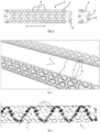
Figure 1 is a front view of a portion of a jewellery item and of a link of such item according to a particular embodiment of the present invention; -
Figure 2 is a perspective view of two portions of jewellery items according to further embodiments of the present invention; -
Figure 3 is a front view of a portion of a jewellery item according to a further embodiment of the present invention; -
Figure 4 is a front view of a portion of a jewellery item according to a further embodiment of the present invention; -
Figure 5 is a cross-sectional view along line V-V ofFigure 4 . -
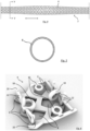
Figure 6 is a perspective view of a longitudinal section of a link, according to a particular embodiment of the present invention; -
Figure 7 shows the link ofFigure 6 connected to an adjacent link; -
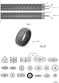
Figures 8 and9 are front views of portions of jewellery items with respective auxiliary supports according to further embodiments of the present invention; -
Figure 10 shows a ring made by using the method of the invention; -
Figure 11 shows a plurality of cross-sections of different jewellery items according to some possible variants of the invention; -
Figures 12a and 12b are, respectively, a perspective view and a front view of a portion of a jewellery item according to a further embodiment of the present invention; -
Figure 13 is a perspective view of a longitudinal section of a link according to a particular embodiment of the present invention. - With reference to the annexed drawings, described herein is a method for making a
jewellery item 2 having an outer surface comprising a plurality oflinks 4 having a complementary shape and intersecting each other. The shape oflinks 4 prevents them from separating. -
Item 2 may be, by way of non-limiting example, a necklace, a bracelet, a ring, etc.Item 2 may be of the openable type, so that it can be worn by a user, or it may comprise elastic means (e.g. an elastic cord) allowing item 2 (e.g. a bracelet) to be widened and worn by the user. The opening and closing means, as well as the elastic means, may be per se known. The invention also concerns anitem 2 made in accordance with any one of the variants of the invention. - In particular, the shape of
links 4 prevents them from separating at least along a direction of longitudinal development ofitem 2.Item 2 has a longitudinal development, weather it is anopenable item 2 or a closed, i.e. circular or annular,item 2. InFigures 1 and4 , an arrow indicates the direction of longitudinal development of the illustrated portion ofitem 2. The cross-sectional view refers to a plane which is transversal or perpendicular to the longitudinal development. - According to the particular embodiments shown in
Figures 1 and 2 ,item 2 has a constant cross-section throughout its longitudinal development. According to some possible variants, the cross-section ofitem 2 varies along its longitudinal development. For example, the shape of the cross-section ofitem 2 does not vary, but its size changes. As an alternative, as shown in the example ofFig. 4 , the shape of the cross-section ofitem 2 varies along its longitudinal development. - With reference to a cross-sectional view of
item 2,links 4 are in a radially external position. In particular,links 4 have a plurality ofprotrusions 6 andrecesses 8. These 6, 8 have a shape which is complementary to that ofrecesses 8 andprotrusions 6 of anadjacent link 4. Therefore,protrusions 6 of alink 4 are inserted inrecesses 8 of anadjacent link 4. In particular,protrusion 6 has a widerdistal part 10 and a narrowerproximal part 12. Thus,links 4 fit together much like the pieces of a puzzle. This ensures a strong connection betweenlinks 4, which prevents them from separating. In the example ofFig. 1 ,protrusions 6 oflinks 4 have a shape resembling a spear head, in particular with a squared profile. In the variant ofFig. 2 ,protrusions 6 have a drop-like shape. In particular,links 4 on the outer surface are not intertwined in a chain-like fashion. In other words,links 4 on the outer surface are mutually constrained only by means of theirrespective protrusions 6 andrecesses 8. - According to one embodiment, all
links 4 have the same shape. In particular, allprotrusions 6 and allrecesses 8 ofsuch links 4 have the same shape. This is the case, for example, of anitem 2 having a constant cross-section throughout its longitudinal development. - In
Figures 1-3 ,items 2 are shown in a straight position, as if they had been laid on a table. However,links 4 make it possible to benditem 2 for wearing it, e.g. around the user's neck or wrist. In fact, betweenlinks 4 there is some play, preferably less than 1 mm, which givesitem 2 flexibility while keepinglinks 4 interconnected. - In a cross-sectional view,
links 4 may have different shapes, e.g. circular, elliptical, oval, polygonal, rectangular, square, etc. Therefore, the outer surface ofitem 2 will have such shapes.Figure 11 shows numerous examples of cross-sections ofitems 2 having different shapes. In the examples ofFigures 2 and5 , the outer surface is, in a cross-sectional view, circular in shape. In accordance with some possible embodiments, the outer surface may be either smooth or corrugated. For example, inFigure 2 upper item 2 has a smooth outer surface, whilelower item 2 has a slightly corrugated or wavy outer surface. - The method comprises the steps of:
- making a 3D print of a prototype having the desired shape of
item 2, - obtaining a mould from the prototype,
- pouring a material in melted state into the mould,
- leaving such melted material to solidify,
- removing the solidified material from the mould.
- The prototype is conveniently made of a material such as, for example, wax or meltable resin, polymeric material, or rubbery material. A 3D printer creates such prototype. Preferably,
item 2 is made of a metallic material or metal alloy such as, for example, gold, silver, steel, titanium, etc. Preferably, the prototype's material has a melting temperature below the melting temperature of the material of the final item 2 (i.e. of the material which is left to solidify in the mould). - If the prototype is in the mould after the mould has been created, there is a step of removing the prototype from the mould. In fact, if the mould is formed around the prototype's body, it will be necessary to remove the prototype from the mould in order to then be able to melt material in said mould. This removal step can be carried out, for example, by melting the prototype, e.g. by putting the prototype and the mould in an oven. The mould will have a cavity with a shape complementary to that of the prototype. The mould is thus created by using the prototype.
- When the mould is internally empty, the material, e.g. metal, is poured into the mould, and
item 2 will thus have the same shape as the prototype. The mould may conveniently be a cast. For example, the mould is made of plaster, scagliola, silicone, or other materials that may be per se known. For example, the mould is made by pouring a liquid or semi-liquid substance, e.g. a paste, around the prototype and then leaving it to solidify. Preferably, the creation of the prototype by 3D printing is directly followed by the step of creating the mould around the prototype; in such mould the melted material of thefinal item 2 will then be poured. Therefore, no other moulds or prototypes need the be created between the 3D printing of the prototype and the creation of the mould. The process is thus fast and simple. - According to some possible embodiments, the
whole item 2, optionally with the exception of hooking means useful for closing it, ifitem 2 is of the openable type, is manufactured by 3D printing. - With reference to
Figure 3 , the method optionally comprises a step of adding adecorative element 14, such as a gem, onto the outer surface ofitem 2. This step follows the step of removing the solidified material from the mould. Thus,item 2 obtained from the mould does not include anydecorative element 14, which will be mounted afterwards, e.g. manually by an operator.Decorative element 14 is fastened to one ormore links 4. In the example there are a plurality ofdecorative elements 14. In particular,links 4 ofitem 2 inFigure 3 have the same shape as those ofitem 2 inFigure 1 . The gem, which may be of any known type, is not limited to a particular material. In fact, the gem may be a stone of precious, natural, mineral, artificial, etc. material, e.g. diamond, sapphire, zircon, ruby, glass, polymer, artificial diamond, etc. InFigure 3 ,decorative elements 14 are gems set ontolinks 4. During the production ofitem 2 using the mould, one or more housings or anchorage portions may be formed onlinks 4 for receivingdecorative elements 14. - In particular, with reference to
Figure 13 ,link 4 includes at least onehousing 26 for receiving a respectivedecorative element 14, such as a stone, e.g. precious stone. In the example, alink 4 includes a plurality ofhousings 26.Housing 26 is connected to link 4 through supporting elements, preferably consisting ofrods 28. Thus, when the user insertsdecorative element 14 intorespective housing 26, the supporting elements, i.e.rods 28 in this example, eliminate the risk oflink 4 being deformed by the user as the latter exerts the force necessary to setdecorative element 14. The at least onehousing 26 is made integrally withlink 4. The supporting elements, consisting ofrods 28 in this example, are made integrally withlink 4. The supporting elements are radially internal to link 4 in a cross-sectional view.Housing 26 faces the outer surface oflink 4. InFig. 13 , the top surface oflink 4 is absent to show the interior of the latter. Optionally,rods 28 may be parts the support structure described below. - According to some possible variants,
item 2 includes a support structure in a radially internal position relative tolinks 4, said support structure being made integrally withlinks 4. Therefore, the support structure is made using 3D printing and the corresponding mould. In other words,item 2 obtained from the mould already includes the support structure. This results in asturdier item 2, without its exterior appearance being affected and with the method remaining fast and economical. - In some possible variants, however, as shown in
Fig. 5 , the support structure is absent. In such a case, links 4 define a wall that constitutes the outer surface, and nothing is present in a position radially internal tolinks 4. In a cross-sectional view,such links 4 define a cavity, and there is nothing in such cavity. Thus, according to some possible embodiments,item 2 is hollow withinlinks 4. In particular, the support structure comprises a plurality ofinterconnected rings links 4. In the example, rings 16, 18 are provided. The support structure is connected to a plurality oflinks 4, preferably to alllinks 4. In a cross-sectional view, rings 16, 18 are radially internal tolinks 4, and hence to the outer surface ofitem 2. With reference toFigures 6 and7 , whereinlinks 4 are displayed in a longitudinal sectional view to show the interior thereof,link 4 is integral with a plurality ofrings rings links 4, preferably alllinks 4, are integral withrespective rings Figure 7 there are twointerconnected links 4, and such twolinks 4 have substantially the same structure, and particularly the same shape.Figure 7 shows twolinks 4 like the one ofFigure 6 joined together. - The rings of one
link 4 may be different from one another. In the example, tworings 16 are smaller, while the other two 18 are bigger.Rings 18 are mutually connected whenlinks 4 are joined. The other rings 16 are connected topins 20 or hooks belonging to the support structure. Therefore, not all rings 16, 18 integral with onelink 4 are directly connected toother rings link 4. Two rings 18 are proximal to two longitudinal ends of therespective link 4 and are connected to correspondingrings 18 of anadjacent link 4, whereas the other tworings 16 are in a substantially central position in therespective link 4, with reference to the longitudinal direction. - Thus, at the end of the 3D printing process the operator removes
item 2 from the mould withrings links 4. - In particular, the support structure may comprise additional elements, such as
rods 22. In the example,rods 22 connect rings 18 to link 4. - According to some further variants shown in
Figures 8 and9 , the step of removing the solidified material from the mould is followed by a step of inserting anauxiliary support 24 withinlinks 4.Auxiliary support 24 performs the same function as the support structure but, unlike the latter,auxiliary support 24 is formed after the creation of the mould. Therefore,auxiliary support 24 is not made integrally with the rest ofitem 2 during the 3D printing process, since it is an additional element, e.g. manually added by the user. According to some possible variants,auxiliary support 24 is one of: a spring, a parallelepipedon, a cylinder. In particular,auxiliary support 24 is inserted in a cavity oflink 4, with reference to a cross-sectional view. - In particular, the examples of
items 2 shown inFigure 11 have either a support structure or anauxiliary support 24. - In general, according to some possible variants,
link 4 is hollow in a cross-sectional view and there are no other parts in a radially internal position withinlink 4 made as one piece with saidlink 4. In the example ofFigure 5 ,link 4 is hollow and there is nothing inside. Alternatively, link 4 is hollow and in the cavity there isauxiliary support 24. - A couple of
auxiliary supports 24 may be inserted in one item, as shown in the first and third images ofFig. 8 . The first two images at the top ofFig. 8 show anauxiliary support 24 shaped as a cylinder or tube. The last two images inFig. 8 show anauxiliary support 24 shaped as a parallelepipedon. InFig. 9 ,auxiliary support 24 is a spring, in particular a coil spring. Preferably, the spring is made of metal. The spring is also useful to increase the flexibility ofjewellery item 2. In general,auxiliary support 24 may be made of different materials, e.g. polymeric or metallic ones. - In particular,
auxiliary support 24 is flexible. Thus,item 2 can be bent, e.g. to be worn around the user's wrist or neck. - In particular,
auxiliary support 24 is added when there is no support structure withinlinks 4.Auxiliary support 24 is inserted withinlinks 4 that are hollow in a cross-sectional view, e.g. like the one shown inFig. 5 . - According to the variant shown in
Figures 12a and 12b , in across-sectional view item 2 is solid withinlinks 4. This means that the cross-section oflink 4 is solid. Therefore, link 4 has no cavity. In the example,item 2 comprises a plurality oflinks 4 that are solid in a cross-sectional view; in particular, alllinks 4 are solid. - Thanks to the present invention, it is possible to manufacture
links 4 ofitem 2 accurately, eliminating any imperfections that might jeopardize the item's strength and flexibility.Links 4 and all other parts ofitem 2 can thus be customized with the utmost versatility using a fast and low-cost production process. - Of course, without prejudice to the principle of the invention, the forms of embodiment and the implementation details may be extensively varied from those described and illustrated herein by way of non-limiting example, without however departing from the scope of the invention as set out in the appended claims.
Claims (13)
- Method for making a jewellery item, which comprises the steps of:• making a 3D print of a prototype having the desired shape of the item (2),• obtaining a mould from the prototype,• pouring a material in melted state into the mould,• leaving such melted material to solidify,• removing the solidified material from the mould;wherein the item (2) has an outer surface comprising a plurality of links (4) having a complementary shape and intersecting each other, wherein the shape of the links (4) prevents them from separating.
- Method according to claim 1, wherein, if the prototype is in the mould after the mould has been created, there is a step of removing the prototype from the mould.
- Method according to claim 1 or 2, wherein the prototype is a material selected among wax, meltable resin, or a polymeric material.
- Method according to any one of the preceding claims, wherein, in a cross-sectional view, the item (2) is hollow within the links (4).
- Method according to any claim from 1 to 3, wherein the item includes a support structure in a radially internal position relative to the links (4), such support structure being made together with the links (4).
- Method according to claim 5, wherein the support structure comprises a plurality of mutually interconnected rings (16, 18) connected to at least some of the links (4).
- Method according to any claim from 1 to 3, wherein the step of removing the solidified material from the mould is followed by the step of inserting an auxiliary support (24) within the links (4).
- Method according to claim 7, wherein the auxiliary support (24) is one of: a spring, a parallelepipedon, a cylinder.
- Method according to any one of the preceding claims, comprising the step of adding a decorative element (14), such as a gem, onto the outer surface of the item (2).
- Method according to any one of the preceding claims, wherein the links (4) have a plurality of protrusions (6) and recesses (8), wherein the protrusions (6) of a link (4) are inserted into the recesses (8) of an adjacent link (4).
- Method according to claim 10, wherein the protrusion (6) has a wider distal part (10) and a narrower proximal part (12).
- Method according to any claim from 1 to 3, wherein the item (2) comprises a plurality of links (4) having a solid cross-section.
- Method according to any one of the preceding claims, wherein the link (4) includes at least one housing (26) for receiving a respective decorative element (14), wherein the housing (26) is connected to the link (4) by means of supporting elements; the at least one housing (26) and the supporting elements are made integrally with the link (4).
Applications Claiming Priority (1)
| Application Number | Priority Date | Filing Date | Title |
|---|---|---|---|
| IT102023000025809A IT202300025809A1 (en) | 2023-12-04 | 2023-12-04 | PROCEDURE FOR MAKING A JEWELRY ITEM |
Publications (1)
| Publication Number | Publication Date |
|---|---|
| EP4566479A1 true EP4566479A1 (en) | 2025-06-11 |
Family
ID=89845141
Family Applications (1)
| Application Number | Title | Priority Date | Filing Date |
|---|---|---|---|
| EP24216736.9A Pending EP4566479A1 (en) | 2023-12-04 | 2024-12-02 | Method for making a jewellery item |
Country Status (2)
| Country | Link |
|---|---|
| EP (1) | EP4566479A1 (en) |
| IT (1) | IT202300025809A1 (en) |
Citations (5)
| Publication number | Priority date | Publication date | Assignee | Title |
|---|---|---|---|---|
| US4279122A (en) * | 1979-09-19 | 1981-07-21 | Dresser Industries, Inc. | Method of making chain |
| US20140305093A1 (en) * | 2013-04-10 | 2014-10-16 | M/s SUNJEWELS INTERNATIONAL PVT. LTD. | Hollow ornaments & process for producing them |
| WO2017059208A1 (en) * | 2015-10-02 | 2017-04-06 | UCT Additive Manufacturing Center Pte. Ltd. | Additive manufactured moveable parts |
| EP3469944A1 (en) * | 2017-10-10 | 2019-04-17 | VOJD GmbH | Ornamental chain, chain link and manufacturing process for manufacturing an ornamental chain |
| KR102536456B1 (en) * | 2022-11-21 | 2023-05-26 | 주식회사 에이유패밀리 | Precious metal hollow ring manufacturing method |
-
2023
- 2023-12-04 IT IT102023000025809A patent/IT202300025809A1/en unknown
-
2024
- 2024-12-02 EP EP24216736.9A patent/EP4566479A1/en active Pending
Patent Citations (5)
| Publication number | Priority date | Publication date | Assignee | Title |
|---|---|---|---|---|
| US4279122A (en) * | 1979-09-19 | 1981-07-21 | Dresser Industries, Inc. | Method of making chain |
| US20140305093A1 (en) * | 2013-04-10 | 2014-10-16 | M/s SUNJEWELS INTERNATIONAL PVT. LTD. | Hollow ornaments & process for producing them |
| WO2017059208A1 (en) * | 2015-10-02 | 2017-04-06 | UCT Additive Manufacturing Center Pte. Ltd. | Additive manufactured moveable parts |
| EP3469944A1 (en) * | 2017-10-10 | 2019-04-17 | VOJD GmbH | Ornamental chain, chain link and manufacturing process for manufacturing an ornamental chain |
| KR102536456B1 (en) * | 2022-11-21 | 2023-05-26 | 주식회사 에이유패밀리 | Precious metal hollow ring manufacturing method |
Also Published As
| Publication number | Publication date |
|---|---|
| IT202300025809A1 (en) | 2025-06-04 |
Similar Documents
| Publication | Publication Date | Title |
|---|---|---|
| US5916271A (en) | Hollow jewelry ring having inner round design | |
| US10271619B1 (en) | Flexible ring structure for jewelry | |
| US6568214B2 (en) | Hinged ring that supports an ornament and a system and method for making same | |
| US4681664A (en) | Process for producing pieces of jewelry from precious metals and pieces of jewelry produced by it | |
| US20050120746A1 (en) | Flexible linkage for jewelry and method of making | |
| EP4566479A1 (en) | Method for making a jewellery item | |
| SK67694A3 (en) | Process for production of casted and set pieces of jewelry | |
| US5881795A (en) | Method of casting metal around gems to form articles of jewelry | |
| US20190387847A1 (en) | Composite article of jewelry and method of making the article | |
| US8966762B2 (en) | Hollow jewelry | |
| US20050005638A1 (en) | Multiple configuration ring | |
| EP3267831B1 (en) | A novel modular element for jewellery or costume jewellery articles | |
| US5758517A (en) | Method and apparatus to set precious stones without hammering | |
| HK1247793A1 (en) | A novel modular element for jewellery or costume jewellery articles | |
| KR101161692B1 (en) | personal ornament and method of producing the same | |
| KR101812932B1 (en) | Jewery accessory and method for manufacturing the same | |
| US6467526B1 (en) | Method of making a jewelry ring in a vertical mold | |
| CN101068482A (en) | Flexible connection device for jewelry and manufacturing method thereof | |
| KR101750152B1 (en) | Glasses decorated coupling structure | |
| KR100332405B1 (en) | Multi casting type jewelery ornaments and manufacture method for multi casting type jewelery ornaments | |
| KR102907848B1 (en) | A ring in which both sides of the ring-shaped decorative part are joined together as one piece | |
| US11771184B2 (en) | Jewelry with non-precious metallic core and process for producing | |
| EP3744211A1 (en) | Decorative elements and methods | |
| KR100313166B1 (en) | Manufacturing method for elastic coupler of ornaments | |
| KR200189132Y1 (en) | Multi casting type jewelery ornaments |
Legal Events
| Date | Code | Title | Description |
|---|---|---|---|
| PUAI | Public reference made under article 153(3) epc to a published international application that has entered the european phase |
Free format text: ORIGINAL CODE: 0009012 |
|
| STAA | Information on the status of an ep patent application or granted ep patent |
Free format text: STATUS: THE APPLICATION HAS BEEN PUBLISHED |
|
| AK | Designated contracting states |
Kind code of ref document: A1 Designated state(s): AL AT BE BG CH CY CZ DE DK EE ES FI FR GB GR HR HU IE IS IT LI LT LU LV MC ME MK MT NL NO PL PT RO RS SE SI SK SM TR |
|
| STAA | Information on the status of an ep patent application or granted ep patent |
Free format text: STATUS: REQUEST FOR EXAMINATION WAS MADE |
|
| 17P | Request for examination filed |
Effective date: 20250723 |