EP4566478A2 - Improvement to the anchoring of the non-slip member to a sole provided with retractable non-slip means - Google Patents
Improvement to the anchoring of the non-slip member to a sole provided with retractable non-slip means Download PDFInfo
- Publication number
- EP4566478A2 EP4566478A2 EP25173480.2A EP25173480A EP4566478A2 EP 4566478 A2 EP4566478 A2 EP 4566478A2 EP 25173480 A EP25173480 A EP 25173480A EP 4566478 A2 EP4566478 A2 EP 4566478A2
- Authority
- EP
- European Patent Office
- Prior art keywords
- slip
- sole
- joint
- slip member
- anchored
- Prior art date
- Legal status (The legal status is an assumption and is not a legal conclusion. Google has not performed a legal analysis and makes no representation as to the accuracy of the status listed.)
- Granted
Links
Images






Classifications
-
- A—HUMAN NECESSITIES
- A43—FOOTWEAR
- A43C—FASTENINGS OR ATTACHMENTS OF FOOTWEAR; LACES IN GENERAL
- A43C15/00—Non-skid devices or attachments
- A43C15/16—Studs or cleats for football or like boots
- A43C15/161—Studs or cleats for football or like boots characterised by the attachment to the sole
-
- A—HUMAN NECESSITIES
- A43—FOOTWEAR
- A43B—CHARACTERISTIC FEATURES OF FOOTWEAR; PARTS OF FOOTWEAR
- A43B13/00—Soles; Sole-and-heel integral units
- A43B13/14—Soles; Sole-and-heel integral units characterised by the constructive form
- A43B13/22—Soles made slip-preventing or wear-resisting, e.g. by impregnation or spreading a wear-resisting layer
- A43B13/24—Soles made slip-preventing or wear-resisting, e.g. by impregnation or spreading a wear-resisting layer by use of insertions
-
- A—HUMAN NECESSITIES
- A43—FOOTWEAR
- A43B—CHARACTERISTIC FEATURES OF FOOTWEAR; PARTS OF FOOTWEAR
- A43B3/00—Footwear characterised by the shape or the use
- A43B3/24—Collapsible or convertible
- A43B3/246—Collapsible or convertible characterised by the sole
-
- A—HUMAN NECESSITIES
- A43—FOOTWEAR
- A43C—FASTENINGS OR ATTACHMENTS OF FOOTWEAR; LACES IN GENERAL
- A43C15/00—Non-skid devices or attachments
- A43C15/02—Non-skid devices or attachments attached to the sole
-
- A—HUMAN NECESSITIES
- A43—FOOTWEAR
- A43C—FASTENINGS OR ATTACHMENTS OF FOOTWEAR; LACES IN GENERAL
- A43C15/00—Non-skid devices or attachments
- A43C15/06—Ice-gripping devices or attachments, e.g. ice-spurs, ice-cleats, ice-creepers, crampons; Climbing devices or attachments, e.g. mountain climbing irons
- A43C15/08—Reversible ice-spikes
-
- A—HUMAN NECESSITIES
- A43—FOOTWEAR
- A43C—FASTENINGS OR ATTACHMENTS OF FOOTWEAR; LACES IN GENERAL
- A43C15/00—Non-skid devices or attachments
- A43C15/14—Non-skid devices or attachments with outwardly-movable spikes
Definitions
- the present invention relates to an improvement of a non-slip device for a shoe sole of the type in which non-slip or skid proof means such as nails or grappling hooks are provided, which are not fixed directly to the sole but to rigid or semi-rigid means which can be folded into grooves obtained in the sole itself.
- the invention relates to an improvement, relating to the anchoring of the support member of the non-slip means to the shoe sole, which will be referred below as a non-slip member for brevity, which can be used:
- the hinging /rotation seats of the non-slip member are not obtained in one piece with the member itself, but an auxiliary member, (in this case in the form of parallelepipeds or cubes) which are anchored as feet to the sole by virtue of a mushroom member with which they are provided, which is snap-fastened into a corresponding seat arranged for molding in the sole next to the groove where the overturnable support member is housed after overturning, without interfering with the integrity of the sole itself, avoiding that a simple twisting of the bottom causes the detachment and loss thereof.
- an auxiliary member in this case in the form of parallelepipeds or cubes
- connection between the member anchored to the sole and the rigid or semi-rigid material member forming the rotation and/or overturning seat of the non-slip member is obtained when they are molded, also incorporating by overmolding, from the same material from which said members are obtained, an appropriate innovative joint which allows molding a single body, preserving the freedom of movement of the different components, but avoiding an accidental splitting of the assembly.
- the member anchored to the sole is thus not detachable from the non-slip member, even applying the elastic force to the sole required for the extraction of the latter.
- Such a result is achieved by providing a joint molded from plastic material, provided with a first steel pin which protrudes above along the axis of symmetry thereof, intended to form the axis of rotation on which the non-slip member can rotate by 180° to be overturned, switching from the rest position to the operating position, while below said joint is provided with an eyelet-like perforated attachment forming the seat intended, in the subsequent overmolding, to shape the member anchored to the sole, with respect to the axis of rotation on which the joint can rotate by 90° with respect to the anchoring plane, and which is perpendicular to the aforementioned first axis of rotation by 180° , so chat the non-slip member can travel a sufficient angular stroke, rising from the containment imprint to allow the complete overturning.
- said joint is reloaded onto a mold which is unique for the entire structure and comprises the shapes of both the non-slip member and the member provided with the sole anchoring means, positioning said joint between the shape of the non-slip member, and that of said anchoring member.
- a plastic material having a melting point different from that of the material from which the joint is made is used for the subsequent molding of the entire structure.
- a structure is thus obtained in one piece, comprising the support member of the nonslip means, the aforementioned joint and the member provided with one or more fastening means for positioning and anchoring it on the shoe sole.
- the entire structure thus allows both lifting the non-slip member with respect to the member which anchors it in the containment imprint thereof obtained in the sole, and rotating the same non-slip member by 180° with respect to the same anchoring member, so as to overturn it when intending to switch from the operating position to the rest position, or vice versa. All the above while avoiding any accidental release.
- the materials from which the joint and the member anchored to the sole are made and which are indicated as a preferred exemplary embodiment herein are Nylon and TPU, but such a choice is not binding, since it is sufficient to use suitable plastic materials having different melting paints and which do not bond together when overmolded.
- the joint 4 is made by inserting, in addition to the double-headed steel pin 6, another steel pin 8 which allows the 90° rotation and in which the mushroom couplings 25 are inserted through special machines after completing the system.
- this does not ensure the permanence in place under significant stresses which can lead to the release of the pin 8 from said mushroom couplings 25.
- the object of the invention is a structure consisting of:
- the joint 14 is thus made integral with both the non-slip grappling-hook holder member 10 and the member 24 anchored to the sole, obtained in one piece with the mushroom pins 25, without preventing the relative movements of one and the other, rotation and overturning, since there is no adhesion between nylon and TPU, as also occurs using any other selected pair of suitable plastic materials having different melting points, which do not bond to each other when overmolded.
- FIG. 11 onwards show the different steps of manufacturing the non-slip system of the invention, including:
Landscapes
- Footwear And Its Accessory, Manufacturing Method And Apparatuses (AREA)
Abstract
Description
- The present invention relates to an improvement of a non-slip device for a shoe sole of the type in which non-slip or skid proof means such as nails or grappling hooks are provided, which are not fixed directly to the sole but to rigid or semi-rigid means which can be folded into grooves obtained in the sole itself.
- More in particular, the invention relates to an improvement, relating to the anchoring of the support member of the non-slip means to the shoe sole, which will be referred below as a non-slip member for brevity, which can be used:
- either in the non-slip device disclosed in
Italian patent 102017000024298 - or with the non-slip device disclosed in
patent EP1558103 , to the same Applicant, where said non-slip means are fixed on rigid or semi-rigid support members which are hinged like a flag to the sole so as to be liftable with respect thereto and which are rotatable by at least 130° with respect to an axis of symmetry thereof which is distinct from the axis of hinging/ lifting with respect to the sole and not parallel thereto, so as to use a single groove to retract the face with the grappling hooks when these are not required to be in contact with the ground. - In both cases, the hinging /rotation seats of the non-slip member are not obtained in one piece with the member itself, but an auxiliary member, (in this case in the form of parallelepipeds or cubes) which are anchored as feet to the sole by virtue of a mushroom member with which they are provided, which is snap-fastened into a corresponding seat arranged for molding in the sole next to the groove where the overturnable support member is housed after overturning, without interfering with the integrity of the sole itself, avoiding that a simple twisting of the bottom causes the detachment and loss thereof.
- However, it hasbeen highlighted that any replacement, due to breakage, loss or abrasion due to accidental causes or wear resulting from constant and prolonged use of the overturnable non-slip member, is rather inconvenient, since many times the traction which allows extracting said overturnable member from the fixing seat, leaves a cube with the fixing mushroom thereof anchored to the sole. This is because, when it is necessary to intervene on the sole, forcing it elastically for the extraction, the greatest stress occurs precisely at the rotation seats of the overturnable non-slip member that are obtained in the cubes, which, not being integral with the body of the same overturnable member, can easily be detached therefrom, remanning anchored to the sole.
- This obviously results in an extension of the replacement times, because the manual extraction of the cube from the housing seat thereof in the sole is also required.
- It has also been highlighted that in the previous solutions a joint had been used, which forms the rotation and/or overturning seat of the non-slip member, which joint is provided with a double-headed through pin made of steel to allow the rotation of the non-slip member by 180° and, perpendicular thereto, another protruding pin made of steel which instead forms the 90° rotation axis of the same non-slip member: the mushroom couplings were thus inserted through this joint using special machines, after completing the entire system.
- However, this solution is complicated and significantly increases the production times and costs.
- It is a first task of the present invention to overcome all the drawbacks of the prior art mentioned above, providing that the member to be anchored to the sole of the non-slip member:
- forms a single body with the means, such as the mushroom members, which allow fixing it to the sole itself; and
- is connected in a non-disassemblable manner to the rigid or semi-rigid material member forming the rotation and/or overturning seat of the non-slip member configuring for this purpose an innovative joint which forms a single body with the non-slip member, avoiding any possible splitting of the assembly.
- It is another task of the invention to overcome all the drawbacks of the prior art mentioned above, providing that the connection between the member anchored to the sole and the rigid or semi-rigid material member forming the rotation and/or overturning seat of the non-slip member, is obtained when they are molded, also incorporating by overmolding, from the same material from which said members are obtained, an appropriate innovative joint which allows molding a single body, preserving the freedom of movement of the different components, but avoiding an accidental splitting of the assembly.
- The member anchored to the sole is thus not detachable from the non-slip member, even applying the elastic force to the sole required for the extraction of the latter.
- Such a result is achieved by providing a joint molded from plastic material, provided with a first steel pin which protrudes above along the axis of symmetry thereof, intended to form the axis of rotation on which the non-slip member can rotate by 180° to be overturned, switching from the rest position to the operating position, while below said joint is provided with an eyelet-like perforated attachment forming the seat intended, in the subsequent overmolding, to shape the member anchored to the sole, with respect to the axis of rotation on which the joint can rotate by 90° with respect to the anchoring plane, and which is perpendicular to the aforementioned first axis of rotation by 180° , so chat the non-slip member can travel a sufficient angular stroke, rising from the containment imprint to allow the complete overturning.
- With such a configuration, once molded, said joint is reloaded onto a mold which is unique for the entire structure and comprises the shapes of both the non-slip member and the member provided with the sole anchoring means, positioning said joint between the shape of the non-slip member, and that of said anchoring member.
- According to a peculiar feature, a plastic material having a melting point different from that of the material from which the joint is made is used for the subsequent molding of the entire structure.
- By molding the two members and simultaneously overmolding the joint, a structure is thus obtained in one piece, comprising the support member of the nonslip means, the aforementioned joint and the member provided with one or more fastening means for positioning and anchoring it on the shoe sole. The entire structure thus allows both lifting the non-slip member with respect to the member which anchors it in the containment imprint thereof obtained in the sole, and rotating the same non-slip member by 180° with respect to the same anchoring member, so as to overturn it when intending to switch from the operating position to the rest position, or vice versa. All the above while avoiding any accidental release. This is because the two different materials from which the pieces of the structure are made, for example , as described below, TPU and Nylon, not binding in any manner to each other, allow the parts, with overmolding, to be connected by means of the steel pin protruding from the joint which is embedded in the non-slip member, and through the formation of a horizontal axis, perpendicular to the previous one which connects the member anchored to the sole to the same joint, however leaving the parts free to rotate freely with respect to each other since there is no adhesion between the two materials forming them. It should be noted that the materials from which the joint and the member anchored to the sole are made and which are indicated as a preferred exemplary embodiment herein are Nylon and TPU, but such a choice is not binding, since it is sufficient to use suitable plastic materials having different melting paints and which do not bond together when overmolded.
- The use of a joint as described and the subsequent overmolding allows:
- avoiding the operation of loading the steel pin when molding the traditional joint, which is replaced by a pin obtained in the overmolding step, in one piece with the member anchored to the sole, with a reduction in both production times and costs;
- eliminating the separate molding of the mushroom coupling means since the entire structure of the finished overturnable member, provided with said coupling means, is obtained when overmolding the joint from another plastic material having a different melting point, in the present case, Nylon with thermoplastic polyurethane TPU;
- then eliminating the assembly of the mushroom couplings after completing the system; and avoiding the accidental release of the mushroom couplings from the steel pin.
- Further features and advantages of the present invention will become apparent from the accompanying drawings which illustrate, only by way of non-limiting example, a preferred embodiment thereof, where there are two mushrooms of the member anchored to the sole.
- In the drawings, figures 1 to 5E relate to the systems in use according to the prior art:
-
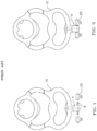
Fig. 1 shows a first non-slip member of known type, in which a joint connected to the shoe sole through two separately molded mushrooms is present; -
Fig. 2 shows the two mushrooms manually assembled with the same joint asFig. 1 , ready to be anchored to the sole in the operating position; -
Figs. 3 and4 show the steps of extracting by traction the non-slip member in the previous figures from the fixing seat thereof on the sole, where the defect often found in practice is highlighted, that is one of the fixing mushrooms, not being Integral with the rest of the structure, remains anchored to the sole, thus lengthening the replacement times; -
Fig. 5A is an exploded view of the different components forming the joint of another more recent non-slip member, showing the need for a complex and laborious assembly of the different components thereof, including a Nylon joint having a double-headed pin for a rotation of 180°, the insertion of a steel pin for a rotation of 90° and the overmolding of a TPU arch as shown inFig. 5B showing a side elevation view of the non-slip member with the grappling hooks facing upwards; -
Fig. 5C shows a perspective view of the same non-slip member, before mounting the mushroom couplings shown inFig. 5D , and -
Fig. 5D finally shows a side elevational view of the non-slip member with the grappling couplings facing downwards after the manual assembly of the mushroom couplings; -
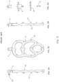
Fig. 6A is a view of the components forming the joint according to the present invention, where the joint is provided with an attachment with an eyelet on one side, while on the opposite side a portion of a double-headed pin protrudes for the 180° rotation of the non-slip member; -
Fig. 6B is a partially section view of the entire structure or complex according to the invention obtained by overmolding the joint inFig. 6A , from a plastic material having a different melting point than that of the material from which the joint is made, where the mushroom couplings are made, directly when molding the entire complex, of the same material that also makes the 90° rotation pin of the non-slip member; -
Fig. 6C is a perspective view of the same structure or complex asFig. 6B , with the non-slip member, the joint and the anchoring member which, only by way of non-limiting example, is provided with a single mushroom coupling; -
Fig. 6D is a side elevation view of the complex inFig. 6C , with the grappling hooks of the non-slip member facing downwards; -
Figs. 7 and8 show how the removal of the non-slip member with grappling hooks according to the invention is easily executable with a simple traction which allows extracting it entirely from the fixing seat thereof, together with the fixing mushroom(s) since they are an integral part of a single structure; -
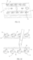
Figs. 9 and10 show, in a different embodiment, the complex consisting of the non-slip member, the joint and the anchoring member inFig. 6 , obtained in one piece after overmolding, when it is positioned in the housing imprint thereof in the sole, and, once lifted from the same imprint, partially rotated with respect to the member connecting it to the sole, respectively; the following figures show the different steps of the method of manufacturing the non-slip member of the invention which can obviously take the most disparate forms, depending on the molds used. In particular:-
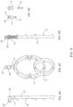
Fig. 11 shows a top plan of a multi-imprint mold for molding the nylon joint, manually loading the double-headed steel pin for the 180° rotation, before molding it; -
Fig. 12 snows the nylon joint, including the steel pin, as it exits from the mold inFig. 11 ; -
Fig. 13 shows the nylon joint complete with pin reloaded on a multi-imprint mold of simple circular design before the TPU overmolding of the entire non-slip system; -
Fig. 14 shows the entire non-slip system complete with joint once the structural coating made of TPU has been overmolded on the nylon joint; -
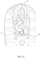
Figs. 15A and 15B show a vertical section plan view and a horizontal section elevation view of the structure or complex consisting of non-slip member, joint and anchoring member infig. 14 , respectively.
-
- As can be seen in
figures 3 and4 , since the currently marketed solutions are not obtained in one piece, they have the serious drawback, apart from including several manual assembly steps, of detaching from each other if subjected to strong traction, whereby it often happens that, during replacement, some fixing members remain in place, and it is therefore necessary to intervene further with a considerable loss of time. - In fact, the
joint 4 is made by inserting, in addition to the double-headed steel pin 6, another steel pin 8 which allows the 90° rotation and in which themushroom couplings 25 are inserted through special machines after completing the system. However, this does not ensure the permanence in place under significant stresses which can lead to the release of the pin 8 from saidmushroom couplings 25. - In order to avoid such a drawback, the views depicted in
figures 6 onwards have been practiced, which show some embodiments of the present invention, only given by way of non-limiting example. - With reference to such figures, the object of the invention is a structure consisting of:
- a non-slip grappling-
hook holder member 10, preferably made of TPU, thermoplastic polyurethane, which is an elastic material with a high resistance to abrasions and chemicals, in the form of bars, arches or even more complex figures, on which nails or grapplinghooks 12 adapted to grip snowy and/or icy surfaces are distributed. - a nylon joint 14, in which a double-headed
steel pin 15 is incorporated for the 180° rotation of the grappling-hook holder member 10, while at theopposite end 16, the same joint 14 is provided with aneyelet 18 forming the seat of the 90°rotation axle 26 of themember 24 fixed to the sole, which is instead perpendicular to the rotation axis of said grappling-hook holder member 10, as seen in the drawings, and - said
member 24 anchored to the sole, made of TPU, i.e. , of the same thermoplastic material as thenon-slip member 10, adapted to be fixed to the sole through one or more fastening means integral therewith, such as the mushroom pins 25 shown infig. 5D , which snap fasten into the corresponding seats arranged in the sole next to the groove where the overturnable support member is housed after overturning. - Once the nylon joint 14 has been obtained by molding, this is reloaded onto a multi-imprint mold for molding the entire structure, positioning it with the
steel pin 15 thereof on thenon-slip member 10, so that it is hinged like a flag, while at the opposite end thereof, in theeyelet 18 , aTPU axle 26 is formed by overmolding, which connects said joint to the anchoringmember 24. - The joint 14 is thus made integral with both the non-slip grappling-
hook holder member 10 and themember 24 anchored to the sole, obtained in one piece with the mushroom pins 25, without preventing the relative movements of one and the other, rotation and overturning, since there is no adhesion between nylon and TPU, as also occurs using any other selected pair of suitable plastic materials having different melting points, which do not bond to each other when overmolded. -
Figures 11 onwards show the different steps of manufacturing the non-slip system of the invention, including: - a) first molding, (
fig. 11 ) from plastic material, for example nylon, in a mold A, which in the case shown is multiple, the joint 14, manually loading the double-headed steel pins so that each joint 14 carries a protrudingsteel pin 15, while at the opposite end said joint is shaped as seen infig. 12 , so as to have a protrudingattachment 16 with aneyelet 18 adapted to form, in a subsequent overmolding, the rotation center of theaxle 26 obtained in one piece with the anchoringmember 24 which is perpendicular to the rotation axis of the non-slip member; - b) providing a multi-imprint mold B arranged for simultaneously molding the
non-slip member 10 and itsmember 24 anchored to the sole, complete withmushroom pins 25, with the interposition of said joint 14; - c) loading said joint 14 into said multi-imprint mold B, positioning it between the imprint of the
non-slip member 10 and that of themember 24 anchored to the sole and carrying out the molding operation by selecting a plastic material having a different melting point than that from which the joint 14 is molded, also overmolding the same joint, so as to obtain thenonslip member 10, themember 24 anchored to the sole and the joint 14 forming a single structure obtained in one piece. It is thus avoided that themember 24 anchored to the sole, in one piece with the mushroom pins 25 thereof, is detachable from thenon-slip member 10, even applying to the sole the elastic force required for the extraction of the latter, as seen infigs. 9 and10 , without preventing the relative movements of one and the other, rotation and overturning, since there is no adhesion between the materials forming them. - A preferred embodiment of the manufacturing has been described herein. It is apparent that several modifications and variations can be made by those skilled in the art, in particular in the number, position and shape of the fixing members carried by the member anchored to the sole, without departing from the scope of protection of the present invention, as defined by the claims as set out below.
Claims (8)
- An improved non-slip device for a shoe sole of the type in which non-slip or skid-proof means such as nails or grappling hooks (12) are provided, such non-slip or skid-proof means (12) being not fixed directly to the sole but to at least one non-slip member (10) that can be folded away into grooves provided in the sole, characterized in that,said non-slip member (10) is provided of one single anchoring member (24) to the sole, which is provided with snap fastening means (25) obtained in one piece with the anchoring member (24),the non-slip member (10) and the anchoring member (24) being connected to each other in a non-disassembled way by a joint (14) provided with a pin (15) integral in use with the non-slip member (10) having a protruding end forming the axis of rotation about which the non-slip member is rotatable through 180°,said joint (14) being provided with a protruding attachment (16) allowing a 90° rotation center of an axle (26) of said member element (24) anchored to the sole, perpendicularly to said pin (15), in which said anchoring member (24) cannot be separated from said non-slip member (10) even if an elastic force necessary for the separation from the latter is applied to the sole.
- A non-slip device for a shoe sole as claimed in any preceding claim, characterized in that fixing means of member (24) anchored to the sole are shaped as one or more mushroom pins (25).
- A non-slip device for a shoe sole as claimed in claim 2, characterized in that the fixing means of member (24) anchored to the sole are shaped as a mushroom pin (25) aligned with attachment (16) of joint (14).
- A non-slip device for a shoe sole as claimed in claim 2, characterized in that the fixing means of member (24) anchored to the sole is shaped as two mushroom pins (25) symmetrically positioned with respect to attachment (16) of joint (14).
- A non-slip device for a shoe sole as claimed in any preceding claim, characterized in that said protruding attachment (16) is housed in use within said anchoring member (24).
- A non-slip device for a shoe sole as claimed in any preceding claim, wherein said non-slip member are in the form of bars, arches or even more complex figures and said non-slip or skid-proof means (12) are nails or grappling hooks distributed on a face of said non-slip member facing downwardly in use.
- A non-slip device for a shoe sole as claimed in claim 6, wherein said non-slip member has a non uniform side thickness having portions having a greater side thickness and portions having a smaller side thickness, said nails or grappling hooks (12) being distributed on portions of the non-slip member having a greater side thickness.
- A shoe sole provided with at least one device according to one of claims 1-7 and comprising at least a groove into which said device according to one of claims 1-7 can be folded, and cavities into which the mushroom pins (25) of said nails or grappling hooks (12) can be fixed.
Priority Applications (2)
| Application Number | Priority Date | Filing Date | Title |
|---|---|---|---|
| RS20260348A RS67898B1 (en) | 2023-05-24 | 2024-05-09 | Improvement to the anchoring of the non-slip member to a sole provided with retractable non-slip means |
| SI202430020T SI4566478T1 (en) | 2023-05-24 | 2024-05-09 | Improvement to the anchoring of the non-slip member to a sole provided with retractable non-slip means |
Applications Claiming Priority (3)
| Application Number | Priority Date | Filing Date | Title |
|---|---|---|---|
| IT102023000010521A IT202300010521A1 (en) | 2023-05-24 | 2023-05-24 | IMPROVEMENT OF THE ANCHORING OF THE ANTI-SLIP ELEMENT TO A SOLE EQUIPPED WITH RETRACTABLE ANTI-SLIP DEVICES AND METHOD FOR ITS CREATION |
| PCT/IB2024/054519 WO2024241131A1 (en) | 2023-05-24 | 2024-05-09 | Improvement to the anchoring of the non-slip member to a sole provided with retractable non-slip means, and related manufaturing method |
| EP24728086.0A EP4489606B8 (en) | 2023-05-24 | 2024-05-09 | Improvement to the anchoring of the non-slip member to a sole provided with retractable non-slip means, and related manufacturing method |
Related Parent Applications (2)
| Application Number | Title | Priority Date | Filing Date |
|---|---|---|---|
| EP24728086.0A Division-Into EP4489606B8 (en) | 2023-05-24 | 2024-05-09 | Improvement to the anchoring of the non-slip member to a sole provided with retractable non-slip means, and related manufacturing method |
| EP24728086.0A Division EP4489606B8 (en) | 2023-05-24 | 2024-05-09 | Improvement to the anchoring of the non-slip member to a sole provided with retractable non-slip means, and related manufacturing method |
Publications (3)
| Publication Number | Publication Date |
|---|---|
| EP4566478A2 true EP4566478A2 (en) | 2025-06-11 |
| EP4566478A3 EP4566478A3 (en) | 2025-07-30 |
| EP4566478B1 EP4566478B1 (en) | 2025-12-24 |
Family
ID=88098039
Family Applications (2)
| Application Number | Title | Priority Date | Filing Date |
|---|---|---|---|
| EP25173480.2A Active EP4566478B1 (en) | 2023-05-24 | 2024-05-09 | Improvement to the anchoring of the non-slip member to a sole provided with retractable non-slip means |
| EP24728086.0A Active EP4489606B8 (en) | 2023-05-24 | 2024-05-09 | Improvement to the anchoring of the non-slip member to a sole provided with retractable non-slip means, and related manufacturing method |
Family Applications After (1)
| Application Number | Title | Priority Date | Filing Date |
|---|---|---|---|
| EP24728086.0A Active EP4489606B8 (en) | 2023-05-24 | 2024-05-09 | Improvement to the anchoring of the non-slip member to a sole provided with retractable non-slip means, and related manufacturing method |
Country Status (15)
| Country | Link |
|---|---|
| EP (2) | EP4566478B1 (en) |
| JP (1) | JP2026516915A (en) |
| KR (1) | KR20260013411A (en) |
| CN (2) | CN121337102A (en) |
| DK (1) | DK4566478T3 (en) |
| ES (1) | ES3037188T3 (en) |
| FI (1) | FI4566478T3 (en) |
| HU (1) | HUE072219T2 (en) |
| IT (1) | IT202300010521A1 (en) |
| LT (1) | LT4566478T (en) |
| MD (1) | MD4489606T2 (en) |
| PL (2) | PL4566478T3 (en) |
| RS (2) | RS67898B1 (en) |
| SI (1) | SI4566478T1 (en) |
| WO (1) | WO2024241131A1 (en) |
Citations (2)
| Publication number | Priority date | Publication date | Assignee | Title |
|---|---|---|---|---|
| EP1558103A1 (en) | 2002-11-05 | 2005-08-03 | AL.Pl. S.r.L. | Improved shoe sole provided with retractable anti-slipping means |
| IT201700024298A1 (en) | 2017-03-03 | 2018-09-03 | Al Pi Srl | "REFINEMENT TO A SOLE EQUIPPED WITH TIPPING ANTI-SLIP MEDIA" |
Family Cites Families (5)
| Publication number | Priority date | Publication date | Assignee | Title |
|---|---|---|---|---|
| KR101188670B1 (en) * | 2010-03-15 | 2012-10-10 | 김형진 | The Outaole of A Shoe for crampon |
| CN201709486U (en) * | 2010-03-31 | 2011-01-19 | 泉州市恒泰鸿伟鞋业有限公司 | Multifunctional antiskid shoe |
| CN202750835U (en) * | 2012-08-16 | 2013-02-27 | 黄文� | Anti-skidding sole |
| KR20140108767A (en) * | 2013-02-27 | 2014-09-15 | 조재균 | Sliding prevention out-sole |
| CN112776251A (en) * | 2019-11-08 | 2021-05-11 | 宜家供应有限公司 | Clothes peg and manufacturing method thereof |
-
2023
- 2023-05-24 IT IT102023000010521A patent/IT202300010521A1/en unknown
-
2024
- 2024-05-09 JP JP2024556644A patent/JP2026516915A/en active Pending
- 2024-05-09 CN CN202511451814.1A patent/CN121337102A/en active Pending
- 2024-05-09 DK DK25173480.2T patent/DK4566478T3/en active
- 2024-05-09 EP EP25173480.2A patent/EP4566478B1/en active Active
- 2024-05-09 KR KR1020247029928A patent/KR20260013411A/en active Pending
- 2024-05-09 EP EP24728086.0A patent/EP4489606B8/en active Active
- 2024-05-09 PL PL25173480.2T patent/PL4566478T3/en unknown
- 2024-05-09 FI FIEP25173480.2T patent/FI4566478T3/en active
- 2024-05-09 CN CN202480001814.9A patent/CN119365096B/en active Active
- 2024-05-09 SI SI202430020T patent/SI4566478T1/en unknown
- 2024-05-09 RS RS20260348A patent/RS67898B1/en unknown
- 2024-05-09 HU HUE24728086A patent/HUE072219T2/en unknown
- 2024-05-09 ES ES24728086T patent/ES3037188T3/en active Active
- 2024-05-09 RS RS20250751A patent/RS67057B1/en unknown
- 2024-05-09 PL PL24728086.0T patent/PL4489606T3/en unknown
- 2024-05-09 MD MDE20250089T patent/MD4489606T2/en unknown
- 2024-05-09 LT LTEP25173480.2T patent/LT4566478T/en unknown
- 2024-05-09 WO PCT/IB2024/054519 patent/WO2024241131A1/en not_active Ceased
Patent Citations (2)
| Publication number | Priority date | Publication date | Assignee | Title |
|---|---|---|---|---|
| EP1558103A1 (en) | 2002-11-05 | 2005-08-03 | AL.Pl. S.r.L. | Improved shoe sole provided with retractable anti-slipping means |
| IT201700024298A1 (en) | 2017-03-03 | 2018-09-03 | Al Pi Srl | "REFINEMENT TO A SOLE EQUIPPED WITH TIPPING ANTI-SLIP MEDIA" |
Also Published As
| Publication number | Publication date |
|---|---|
| JP2026516915A (en) | 2026-05-27 |
| HUE072219T2 (en) | 2025-11-28 |
| PL4489606T3 (en) | 2025-09-22 |
| ES3037188T3 (en) | 2025-09-30 |
| EP4489606B8 (en) | 2025-07-23 |
| DK4566478T3 (en) | 2026-03-02 |
| EP4489606B1 (en) | 2025-05-07 |
| SI4566478T1 (en) | 2026-05-29 |
| MD4489606T2 (en) | 2025-09-30 |
| CN121337102A (en) | 2026-01-16 |
| CN119365096A (en) | 2025-01-24 |
| CN119365096B (en) | 2025-12-02 |
| PL4566478T3 (en) | 2026-03-30 |
| RS67057B1 (en) | 2025-08-29 |
| RS67898B1 (en) | 2026-04-30 |
| WO2024241131A1 (en) | 2024-11-28 |
| EP4489606A1 (en) | 2025-01-15 |
| EP4566478B1 (en) | 2025-12-24 |
| EP4489606C0 (en) | 2025-05-07 |
| LT4566478T (en) | 2026-03-10 |
| IT202300010521A1 (en) | 2024-11-24 |
| FI4566478T3 (en) | 2026-02-27 |
| KR20260013411A (en) | 2026-01-28 |
| EP4566478A3 (en) | 2025-07-30 |
Similar Documents
| Publication | Publication Date | Title |
|---|---|---|
| US7047675B2 (en) | Detachable cleat system | |
| US9901141B2 (en) | Method for making a cleated plate | |
| KR100530473B1 (en) | Golf shoe cleat and method for producing golf shoe cleat | |
| EP4566478B1 (en) | Improvement to the anchoring of the non-slip member to a sole provided with retractable non-slip means | |
| US6779312B2 (en) | Anchoring device | |
| HK40125170A (en) | Improvement to the anchoring of the non-slip member to a sole provided with retractable non-slip means | |
| HK40125170B (en) | Improvement to the anchoring of the non-slip member to a sole provided with retractable non-slip means | |
| HK40115664B (en) | Improvement to the anchoring of the non-slip member to a sole provided with retractable non-slip means, and related manufacturing method | |
| HK40115664A (en) | Improvement to the anchoring of the non-slip member to a sole provided with retractable non-slip means, and related manufacturing method | |
| US20180070680A1 (en) | Traction Studs And Outsoles | |
| CA3054263A1 (en) | Improved sole provided with overturning anti-slipping means | |
| CN100443362C (en) | Quick-connect plate for cyclists' shoes | |
| EP1834536B1 (en) | Sole and method for the manufacture of a sole | |
| EA049645B1 (en) | IMPROVEMENT OF THE FASTENING OF THE ANTI-SLIP ELEMENT TO THE SOLE EQUIPPED WITH RETRACTABLE ANTI-SLIP MEANS AND THE CORRESPONDING MANUFACTURING METHOD | |
| EP0349308B1 (en) | Improved last | |
| GB1586025A (en) | Boot or article of footwear and a process of manufacturing the same | |
| US1727412A (en) | Tread member for boots and shoes and method of making the same | |
| JP3204287U (en) | Positioning molding structure of spike pin and shoe sole | |
| JP7818853B1 (en) | Shoes with anti-slip hardware | |
| US3034160A (en) | Shoemakers' lasts | |
| US3083386A (en) | Shoemakers' lasts | |
| US20010010421A1 (en) | Ski binding with a demountable brake | |
| EP1473144B1 (en) | Method for making an article of footwear | |
| WO2002089622A2 (en) | Modified sole for thong footwear or sandals, mould and method for making the same | |
| JPH0341901A (en) | Nonslip outsole and its manufacture |
Legal Events
| Date | Code | Title | Description |
|---|---|---|---|
| PUAI | Public reference made under article 153(3) epc to a published international application that has entered the european phase |
Free format text: ORIGINAL CODE: 0009012 |
|
| STAA | Information on the status of an ep patent application or granted ep patent |
Free format text: STATUS: THE APPLICATION HAS BEEN PUBLISHED |
|
| AC | Divisional application: reference to earlier application |
Ref document number: 4489606 Country of ref document: EP Kind code of ref document: P |
|
| AK | Designated contracting states |
Kind code of ref document: A2 Designated state(s): AL AT BE BG CH CY CZ DE DK EE ES FI FR GB GR HR HU IE IS IT LI LT LU LV MC ME MK MT NL NO PL PT RO RS SE SI SK SM TR |
|
| PUAL | Search report despatched |
Free format text: ORIGINAL CODE: 0009013 |
|
| AK | Designated contracting states |
Kind code of ref document: A3 Designated state(s): AL AT BE BG CH CY CZ DE DK EE ES FI FR GB GR HR HU IE IS IT LI LT LU LV MC ME MK MT NL NO PL PT RO RS SE SI SK SM TR |
|
| RIC1 | Information provided on ipc code assigned before grant |
Ipc: A43C 15/16 20060101AFI20250624BHEP Ipc: A43B 3/24 20060101ALI20250624BHEP Ipc: A43C 15/08 20060101ALI20250624BHEP |
|
| STAA | Information on the status of an ep patent application or granted ep patent |
Free format text: STATUS: REQUEST FOR EXAMINATION WAS MADE |
|
| GRAP | Despatch of communication of intention to grant a patent |
Free format text: ORIGINAL CODE: EPIDOSNIGR1 |
|
| STAA | Information on the status of an ep patent application or granted ep patent |
Free format text: STATUS: GRANT OF PATENT IS INTENDED |
|
| GRAS | Grant fee paid |
Free format text: ORIGINAL CODE: EPIDOSNIGR3 |
|
| 17P | Request for examination filed |
Effective date: 20251014 |
|
| RAV | Requested validation state of the european patent: fee paid |
Extension state: GE Effective date: 20251014 Extension state: MD Effective date: 20251014 |
|
| RAX | Requested extension states of the european patent have changed |
Extension state: BA Payment date: 20251014 |
|
| GRAA | (expected) grant |
Free format text: ORIGINAL CODE: 0009210 |
|
| STAA | Information on the status of an ep patent application or granted ep patent |
Free format text: STATUS: THE PATENT HAS BEEN GRANTED |
|
| INTG | Intention to grant announced |
Effective date: 20251024 |
|
| REG | Reference to a national code |
Ref country code: HK Ref legal event code: DE Ref document number: 40125170 Country of ref document: HK |
|
| AC | Divisional application: reference to earlier application |
Ref document number: 4489606 Country of ref document: EP Kind code of ref document: P |
|
| AK | Designated contracting states |
Kind code of ref document: B1 Designated state(s): AL AT BE BG CH CY CZ DE DK EE ES FI FR GB GR HR HU IE IS IT LI LT LU LV MC ME MK MT NL NO PL PT RO RS SE SI SK SM TR |
|
| REG | Reference to a national code |
Ref country code: CH Ref legal event code: F10 Free format text: ST27 STATUS EVENT CODE: U-0-0-F10-F00 (AS PROVIDED BY THE NATIONAL OFFICE) Effective date: 20251224 Ref country code: GB Ref legal event code: FG4D |
|
| REG | Reference to a national code |
Ref country code: DE Ref legal event code: R096 Ref document number: 602024001836 Country of ref document: DE |
|
| REG | Reference to a national code |
Ref country code: CH Ref legal event code: R17 Free format text: ST27 STATUS EVENT CODE: U-0-0-R10-R17 (AS PROVIDED BY THE NATIONAL OFFICE) Effective date: 20260223 |
|
| REG | Reference to a national code |
Ref country code: FI Ref legal event code: FGE |
|
| REG | Reference to a national code |
Ref country code: DK Ref legal event code: T3 Effective date: 20260227 |
|
| P01 | Opt-out of the competence of the unified patent court (upc) registered |
Free format text: CASE NUMBER: UPC_APP_0003434_4566478/2026 Effective date: 20260130 |
|
| REG | Reference to a national code |
Ref country code: NL Ref legal event code: FP |
|
| PG25 | Lapsed in a contracting state [announced via postgrant information from national office to epo] |
Ref country code: HR Free format text: LAPSE BECAUSE OF FAILURE TO SUBMIT A TRANSLATION OF THE DESCRIPTION OR TO PAY THE FEE WITHIN THE PRESCRIBED TIME-LIMIT Effective date: 20251224 |
|
| REG | Reference to a national code |
Ref country code: EE Ref legal event code: FG4A Ref document number: E025668 Country of ref document: EE Effective date: 20260223 |
|
| REG | Reference to a national code |
Ref country code: SK Ref legal event code: T3 Ref document number: E 48126 Country of ref document: SK |
|
| PG25 | Lapsed in a contracting state [announced via postgrant information from national office to epo] |
Ref country code: SM Free format text: LAPSE BECAUSE OF FAILURE TO SUBMIT A TRANSLATION OF THE DESCRIPTION OR TO PAY THE FEE WITHIN THE PRESCRIBED TIME-LIMIT Effective date: 20251224 |
|
| PG25 | Lapsed in a contracting state [announced via postgrant information from national office to epo] |
Ref country code: ES Free format text: LAPSE BECAUSE OF FAILURE TO SUBMIT A TRANSLATION OF THE DESCRIPTION OR TO PAY THE FEE WITHIN THE PRESCRIBED TIME-LIMIT Effective date: 20251224 |
|
| PGFP | Annual fee paid to national office [announced via postgrant information from national office to epo] |
Ref country code: RS Payment date: 20260423 Year of fee payment: 3 Ref country code: DK Payment date: 20260528 Year of fee payment: 3 Ref country code: PL Payment date: 20260420 Year of fee payment: 3 |
|
| PGFP | Annual fee paid to national office [announced via postgrant information from national office to epo] |
Ref country code: IT Payment date: 20260601 Year of fee payment: 3 |
|
| PGFP | Annual fee paid to national office [announced via postgrant information from national office to epo] |
Ref country code: LT Payment date: 20260423 Year of fee payment: 3 Ref country code: DE Payment date: 20260602 Year of fee payment: 3 |
|
| PGFP | Annual fee paid to national office [announced via postgrant information from national office to epo] |
Ref country code: NO Payment date: 20260521 Year of fee payment: 3 |
|
| VS25 | Lapsed in a validation state [announced via postgrant information from nat. office to epo] |
Ref country code: MD Free format text: LAPSE BECAUSE OF FAILURE TO SUBMIT A TRANSLATION OF THE DESCRIPTION OR TO PAY THE FEE WITHIN THE PRESCRIBED TIME-LIMIT Effective date: 20251224 |
|
| PGFP | Annual fee paid to national office [announced via postgrant information from national office to epo] |
Ref country code: AT Payment date: 20260714 Year of fee payment: 3 Ref country code: FI Payment date: 20260530 Year of fee payment: 3 Ref country code: SE Payment date: 20260528 Year of fee payment: 3 |
|
| PGFP | Annual fee paid to national office [announced via postgrant information from national office to epo] |
Ref country code: RO Payment date: 20260504 Year of fee payment: 3 Ref country code: BE Payment date: 20260527 Year of fee payment: 3 |
|
| PGFP | Annual fee paid to national office [announced via postgrant information from national office to epo] |
Ref country code: EE Payment date: 20260522 Year of fee payment: 3 |
|
| PG25 | Lapsed in a contracting state [announced via postgrant information from national office to epo] |
Ref country code: PT Free format text: LAPSE BECAUSE OF FAILURE TO SUBMIT A TRANSLATION OF THE DESCRIPTION OR TO PAY THE FEE WITHIN THE PRESCRIBED TIME-LIMIT Effective date: 20260424 |
|
| PGFP | Annual fee paid to national office [announced via postgrant information from national office to epo] |
Ref country code: IS Payment date: 20260511 Year of fee payment: 3 |
|
| PGFP | Annual fee paid to national office [announced via postgrant information from national office to epo] |
Ref country code: CZ Payment date: 20260423 Year of fee payment: 3 Ref country code: TR Payment date: 20260504 Year of fee payment: 3 |
|
| PGFP | Annual fee paid to national office [announced via postgrant information from national office to epo] |
Ref country code: FR Payment date: 20260528 Year of fee payment: 3 |
|
| PGFP | Annual fee paid to national office [announced via postgrant information from national office to epo] |
Ref country code: LV Payment date: 20260520 Year of fee payment: 3 |
|
| PGFP | Annual fee paid to national office [announced via postgrant information from national office to epo] |
Ref country code: SK Payment date: 20260424 Year of fee payment: 3 |
|
| PGFP | Annual fee paid to national office [announced via postgrant information from national office to epo] |
Ref country code: BG Payment date: 20260529 Year of fee payment: 3 |
|
| PGFP | Annual fee paid to national office [announced via postgrant information from national office to epo] |
Ref country code: SI Payment date: 20260424 Year of fee payment: 3 |
|
| VS25 | Lapsed in a validation state [announced via postgrant information from nat. office to epo] |
Ref country code: GE Free format text: LAPSE BECAUSE OF FAILURE TO SUBMIT A TRANSLATION OF THE DESCRIPTION OR TO PAY THE FEE WITHIN THE PRESCRIBED TIME-LIMIT Effective date: 20251224 |