EP4565016A1 - Automated control of an electrical connection joining process - Google Patents
Automated control of an electrical connection joining process Download PDFInfo
- Publication number
- EP4565016A1 EP4565016A1 EP24215627.1A EP24215627A EP4565016A1 EP 4565016 A1 EP4565016 A1 EP 4565016A1 EP 24215627 A EP24215627 A EP 24215627A EP 4565016 A1 EP4565016 A1 EP 4565016A1
- Authority
- EP
- European Patent Office
- Prior art keywords
- resistance
- joining tool
- flexible circuit
- pad
- connection
- Prior art date
- Legal status (The legal status is an assumption and is not a legal conclusion. Google has not performed a legal analysis and makes no representation as to the accuracy of the status listed.)
- Withdrawn
Links
Images


Classifications
-
- H—ELECTRICITY
- H05—ELECTRIC TECHNIQUES NOT OTHERWISE PROVIDED FOR
- H05K—PRINTED CIRCUITS; CASINGS OR CONSTRUCTIONAL DETAILS OF ELECTRIC APPARATUS; MANUFACTURE OF ASSEMBLAGES OF ELECTRICAL COMPONENTS
- H05K3/00—Apparatus or processes for manufacturing printed circuits
- H05K3/30—Assembling printed circuits with electric components, e.g. with resistors
- H05K3/32—Assembling printed circuits with electric components, e.g. with resistors electrically connecting electric components or wires to printed circuits
- H05K3/34—Assembling printed circuits with electric components, e.g. with resistors electrically connecting electric components or wires to printed circuits by soldering
-
- H—ELECTRICITY
- H05—ELECTRIC TECHNIQUES NOT OTHERWISE PROVIDED FOR
- H05K—PRINTED CIRCUITS; CASINGS OR CONSTRUCTIONAL DETAILS OF ELECTRIC APPARATUS; MANUFACTURE OF ASSEMBLAGES OF ELECTRICAL COMPONENTS
- H05K1/00—Printed circuits
- H05K1/02—Details
- H05K1/0266—Marks, test patterns or identification means
- H05K1/0268—Marks, test patterns or identification means for electrical inspection or testing
-
- B—PERFORMING OPERATIONS; TRANSPORTING
- B23—MACHINE TOOLS; METAL-WORKING NOT OTHERWISE PROVIDED FOR
- B23K—SOLDERING OR UNSOLDERING; WELDING; CLADDING OR PLATING BY SOLDERING OR WELDING; CUTTING BY APPLYING HEAT LOCALLY, e.g. FLAME CUTTING; WORKING BY LASER BEAM
- B23K3/00—Tools, devices or special appurtenances for soldering, e.g. brazing, or unsoldering, not specially adapted for particular methods
- B23K3/02—Soldering irons; Bits
- B23K3/03—Soldering irons; Bits electrically heated
- B23K3/033—Soldering irons; Bits electrically heated comprising means for controlling or selecting the temperature or power
-
- A—HUMAN NECESSITIES
- A61—MEDICAL OR VETERINARY SCIENCE; HYGIENE
- A61B—DIAGNOSIS; SURGERY; IDENTIFICATION
- A61B18/00—Surgical instruments, devices or methods for transferring non-mechanical forms of energy to or from the body
- A61B18/04—Surgical instruments, devices or methods for transferring non-mechanical forms of energy to or from the body by heating
- A61B18/12—Surgical instruments, devices or methods for transferring non-mechanical forms of energy to or from the body by heating by passing a current through the tissue to be heated, e.g. high-frequency current
- A61B18/14—Probes or electrodes therefor
- A61B18/1492—Probes or electrodes therefor having a flexible, catheter-like structure, e.g. for heart ablation
-
- A—HUMAN NECESSITIES
- A61—MEDICAL OR VETERINARY SCIENCE; HYGIENE
- A61N—ELECTROTHERAPY; MAGNETOTHERAPY; RADIATION THERAPY; ULTRASOUND THERAPY
- A61N1/00—Electrotherapy; Circuits therefor
- A61N1/02—Details
-
- A—HUMAN NECESSITIES
- A61—MEDICAL OR VETERINARY SCIENCE; HYGIENE
- A61N—ELECTROTHERAPY; MAGNETOTHERAPY; RADIATION THERAPY; ULTRASOUND THERAPY
- A61N1/00—Electrotherapy; Circuits therefor
- A61N1/02—Details
- A61N1/04—Electrodes
- A61N1/05—Electrodes for implantation or insertion into the body, e.g. heart electrode
- A61N1/056—Transvascular endocardial electrode systems
-
- A—HUMAN NECESSITIES
- A61—MEDICAL OR VETERINARY SCIENCE; HYGIENE
- A61N—ELECTROTHERAPY; MAGNETOTHERAPY; RADIATION THERAPY; ULTRASOUND THERAPY
- A61N1/00—Electrotherapy; Circuits therefor
- A61N1/02—Details
- A61N1/04—Electrodes
- A61N1/05—Electrodes for implantation or insertion into the body, e.g. heart electrode
- A61N1/056—Transvascular endocardial electrode systems
- A61N1/0565—Electrode heads
-
- A—HUMAN NECESSITIES
- A61—MEDICAL OR VETERINARY SCIENCE; HYGIENE
- A61N—ELECTROTHERAPY; MAGNETOTHERAPY; RADIATION THERAPY; ULTRASOUND THERAPY
- A61N1/00—Electrotherapy; Circuits therefor
- A61N1/02—Details
- A61N1/04—Electrodes
- A61N1/05—Electrodes for implantation or insertion into the body, e.g. heart electrode
- A61N1/056—Transvascular endocardial electrode systems
- A61N1/057—Anchoring means; Means for fixing the head inside the heart
-
- B—PERFORMING OPERATIONS; TRANSPORTING
- B23—MACHINE TOOLS; METAL-WORKING NOT OTHERWISE PROVIDED FOR
- B23K—SOLDERING OR UNSOLDERING; WELDING; CLADDING OR PLATING BY SOLDERING OR WELDING; CUTTING BY APPLYING HEAT LOCALLY, e.g. FLAME CUTTING; WORKING BY LASER BEAM
- B23K1/00—Soldering, e.g. brazing, or unsoldering
- B23K1/0004—Resistance soldering
-
- B—PERFORMING OPERATIONS; TRANSPORTING
- B23—MACHINE TOOLS; METAL-WORKING NOT OTHERWISE PROVIDED FOR
- B23K—SOLDERING OR UNSOLDERING; WELDING; CLADDING OR PLATING BY SOLDERING OR WELDING; CUTTING BY APPLYING HEAT LOCALLY, e.g. FLAME CUTTING; WORKING BY LASER BEAM
- B23K1/00—Soldering, e.g. brazing, or unsoldering
- B23K1/0008—Soldering, e.g. brazing, or unsoldering specially adapted for particular articles or work
- B23K1/0016—Soldering of electronic components
-
- H—ELECTRICITY
- H05—ELECTRIC TECHNIQUES NOT OTHERWISE PROVIDED FOR
- H05K—PRINTED CIRCUITS; CASINGS OR CONSTRUCTIONAL DETAILS OF ELECTRIC APPARATUS; MANUFACTURE OF ASSEMBLAGES OF ELECTRICAL COMPONENTS
- H05K1/00—Printed circuits
- H05K1/02—Details
- H05K1/11—Printed elements for providing electric connections to or between printed circuits
- H05K1/111—Pads for surface mounting, e.g. lay-out
-
- H—ELECTRICITY
- H05—ELECTRIC TECHNIQUES NOT OTHERWISE PROVIDED FOR
- H05K—PRINTED CIRCUITS; CASINGS OR CONSTRUCTIONAL DETAILS OF ELECTRIC APPARATUS; MANUFACTURE OF ASSEMBLAGES OF ELECTRICAL COMPONENTS
- H05K1/00—Printed circuits
- H05K1/18—Printed circuits structurally associated with non-printed electric components
- H05K1/181—Printed circuits structurally associated with non-printed electric components associated with surface mounted components
-
- H—ELECTRICITY
- H05—ELECTRIC TECHNIQUES NOT OTHERWISE PROVIDED FOR
- H05K—PRINTED CIRCUITS; CASINGS OR CONSTRUCTIONAL DETAILS OF ELECTRIC APPARATUS; MANUFACTURE OF ASSEMBLAGES OF ELECTRICAL COMPONENTS
- H05K3/00—Apparatus or processes for manufacturing printed circuits
- H05K3/0008—Apparatus or processes for manufacturing printed circuits for aligning or positioning of tools relative to the circuit board
-
- H—ELECTRICITY
- H05—ELECTRIC TECHNIQUES NOT OTHERWISE PROVIDED FOR
- H05K—PRINTED CIRCUITS; CASINGS OR CONSTRUCTIONAL DETAILS OF ELECTRIC APPARATUS; MANUFACTURE OF ASSEMBLAGES OF ELECTRICAL COMPONENTS
- H05K3/00—Apparatus or processes for manufacturing printed circuits
- H05K3/30—Assembling printed circuits with electric components, e.g. with resistors
- H05K3/32—Assembling printed circuits with electric components, e.g. with resistors electrically connecting electric components or wires to printed circuits
- H05K3/328—Assembling printed circuits with electric components, e.g. with resistors electrically connecting electric components or wires to printed circuits by welding
-
- H—ELECTRICITY
- H05—ELECTRIC TECHNIQUES NOT OTHERWISE PROVIDED FOR
- H05K—PRINTED CIRCUITS; CASINGS OR CONSTRUCTIONAL DETAILS OF ELECTRIC APPARATUS; MANUFACTURE OF ASSEMBLAGES OF ELECTRICAL COMPONENTS
- H05K3/00—Apparatus or processes for manufacturing printed circuits
- H05K3/30—Assembling printed circuits with electric components, e.g. with resistors
- H05K3/32—Assembling printed circuits with electric components, e.g. with resistors electrically connecting electric components or wires to printed circuits
- H05K3/34—Assembling printed circuits with electric components, e.g. with resistors electrically connecting electric components or wires to printed circuits by soldering
- H05K3/341—Surface mounted components
-
- B—PERFORMING OPERATIONS; TRANSPORTING
- B23—MACHINE TOOLS; METAL-WORKING NOT OTHERWISE PROVIDED FOR
- B23K—SOLDERING OR UNSOLDERING; WELDING; CLADDING OR PLATING BY SOLDERING OR WELDING; CUTTING BY APPLYING HEAT LOCALLY, e.g. FLAME CUTTING; WORKING BY LASER BEAM
- B23K2101/00—Articles made by soldering, welding or cutting
- B23K2101/36—Electric or electronic devices
- B23K2101/42—Printed circuits
-
- H—ELECTRICITY
- H05—ELECTRIC TECHNIQUES NOT OTHERWISE PROVIDED FOR
- H05K—PRINTED CIRCUITS; CASINGS OR CONSTRUCTIONAL DETAILS OF ELECTRIC APPARATUS; MANUFACTURE OF ASSEMBLAGES OF ELECTRICAL COMPONENTS
- H05K1/00—Printed circuits
- H05K1/18—Printed circuits structurally associated with non-printed electric components
- H05K1/189—Printed circuits structurally associated with non-printed electric components characterised by the use of flexible or folded printed circuits
-
- H—ELECTRICITY
- H05—ELECTRIC TECHNIQUES NOT OTHERWISE PROVIDED FOR
- H05K—PRINTED CIRCUITS; CASINGS OR CONSTRUCTIONAL DETAILS OF ELECTRIC APPARATUS; MANUFACTURE OF ASSEMBLAGES OF ELECTRICAL COMPONENTS
- H05K2201/00—Indexing scheme relating to printed circuits covered by H05K1/00
- H05K2201/09—Shape and layout
- H05K2201/09209—Shape and layout details of conductors
- H05K2201/09372—Pads and lands
- H05K2201/09445—Pads for connections not located at the edge of the PCB, e.g. for flexible circuits
-
- H—ELECTRICITY
- H05—ELECTRIC TECHNIQUES NOT OTHERWISE PROVIDED FOR
- H05K—PRINTED CIRCUITS; CASINGS OR CONSTRUCTIONAL DETAILS OF ELECTRIC APPARATUS; MANUFACTURE OF ASSEMBLAGES OF ELECTRICAL COMPONENTS
- H05K2201/00—Indexing scheme relating to printed circuits covered by H05K1/00
- H05K2201/09—Shape and layout
- H05K2201/09209—Shape and layout details of conductors
- H05K2201/09654—Shape and layout details of conductors covering at least two types of conductors provided for in H05K2201/09218 - H05K2201/095
- H05K2201/09672—Superposed layout, i.e. in different planes
-
- H—ELECTRICITY
- H05—ELECTRIC TECHNIQUES NOT OTHERWISE PROVIDED FOR
- H05K—PRINTED CIRCUITS; CASINGS OR CONSTRUCTIONAL DETAILS OF ELECTRIC APPARATUS; MANUFACTURE OF ASSEMBLAGES OF ELECTRICAL COMPONENTS
- H05K2201/00—Indexing scheme relating to printed circuits covered by H05K1/00
- H05K2201/09—Shape and layout
- H05K2201/09209—Shape and layout details of conductors
- H05K2201/09654—Shape and layout details of conductors covering at least two types of conductors provided for in H05K2201/09218 - H05K2201/095
- H05K2201/09781—Dummy conductors, i.e. not used for normal transport of current; Dummy electrodes of components
-
- H—ELECTRICITY
- H05—ELECTRIC TECHNIQUES NOT OTHERWISE PROVIDED FOR
- H05K—PRINTED CIRCUITS; CASINGS OR CONSTRUCTIONAL DETAILS OF ELECTRIC APPARATUS; MANUFACTURE OF ASSEMBLAGES OF ELECTRICAL COMPONENTS
- H05K2201/00—Indexing scheme relating to printed circuits covered by H05K1/00
- H05K2201/10—Details of components or other objects attached to or integrated in a printed circuit board
- H05K2201/10227—Other objects, e.g. metallic pieces
- H05K2201/10287—Metal wires as connectors or conductors
-
- H—ELECTRICITY
- H05—ELECTRIC TECHNIQUES NOT OTHERWISE PROVIDED FOR
- H05K—PRINTED CIRCUITS; CASINGS OR CONSTRUCTIONAL DETAILS OF ELECTRIC APPARATUS; MANUFACTURE OF ASSEMBLAGES OF ELECTRICAL COMPONENTS
- H05K2203/00—Indexing scheme relating to apparatus or processes for manufacturing printed circuits covered by H05K3/00
- H05K2203/02—Details related to mechanical or acoustic processing, e.g. drilling, punching, cutting, using ultrasound
- H05K2203/0285—Using ultrasound, e.g. for cleaning, soldering or wet treatment
-
- H—ELECTRICITY
- H05—ELECTRIC TECHNIQUES NOT OTHERWISE PROVIDED FOR
- H05K—PRINTED CIRCUITS; CASINGS OR CONSTRUCTIONAL DETAILS OF ELECTRIC APPARATUS; MANUFACTURE OF ASSEMBLAGES OF ELECTRICAL COMPONENTS
- H05K2203/00—Indexing scheme relating to apparatus or processes for manufacturing printed circuits covered by H05K3/00
- H05K2203/16—Inspection; Monitoring; Aligning
- H05K2203/163—Monitoring a manufacturing process
-
- H—ELECTRICITY
- H05—ELECTRIC TECHNIQUES NOT OTHERWISE PROVIDED FOR
- H05K—PRINTED CIRCUITS; CASINGS OR CONSTRUCTIONAL DETAILS OF ELECTRIC APPARATUS; MANUFACTURE OF ASSEMBLAGES OF ELECTRICAL COMPONENTS
- H05K2203/00—Indexing scheme relating to apparatus or processes for manufacturing printed circuits covered by H05K3/00
- H05K2203/16—Inspection; Monitoring; Aligning
- H05K2203/165—Stabilizing, e.g. temperature stabilization
-
- H—ELECTRICITY
- H05—ELECTRIC TECHNIQUES NOT OTHERWISE PROVIDED FOR
- H05K—PRINTED CIRCUITS; CASINGS OR CONSTRUCTIONAL DETAILS OF ELECTRIC APPARATUS; MANUFACTURE OF ASSEMBLAGES OF ELECTRICAL COMPONENTS
- H05K2203/00—Indexing scheme relating to apparatus or processes for manufacturing printed circuits covered by H05K3/00
- H05K2203/16—Inspection; Monitoring; Aligning
- H05K2203/166—Alignment or registration; Control of registration
Definitions
- the present disclosure in some embodiments thereof, relates to catheter manufacture and, more particularly, but not exclusively, to establishing electrical connections to a flexible circuit strip of the catheter.
- Electrode catheters have been in common use in medical practice for many years. They are used to stimulate and map electrical activity in the heart and to ablate sites of aberrant electrical activity.
- a wall cavity of an organ of a patient can be mapped and/or ablated using a catheter having multiple electrodes fitted at an expandable distal end assembly of the catheter.
- the expandable distal-end assembly is coupled at a distal end of a catheter shaft for insertion into the cavity.
- the expandable distal end assembly may be shaped in the form of a balloon, basket and/or another type of cage and may include a plurality of electrodes configured for sensing and/or delivering therapeutic signals.
- the present disclosure in some embodiments, thereof, relates to catheter manufacture and, more particularly, but not exclusively, to establishing electrical connections to a flexible circuit strip of the catheter.
- Some catheters such as basket catheters, may have many (e.g., 30-100) electrodes mounted on a plurality of splines of the basket, which is coupled through a shaft of the catheter to a connector at the proximal end of the shaft.
- the electrodes may be hosted by a plurality of flexible printed circuit boards (PCB) each of which is mounted on a spline of the basket.
- PCBs also herein termed "flexible circuit strip" on the splines and a PCB of the connector have pads and a plurality of wires, e.g., a wire for each electrode, running through the shaft, provides electrical coupling.
- each wire is coupled to a predefined pad on the spline, and a proximal end of each wire is coupled to a corresponding pad in the connector, so as to exchange electrical signals between the electrodes and a control console, e.g., a PIU (patient interface unit) of the catheter, via the shaft.
- a control console e.g., a PIU (patient interface unit) of the catheter
- the pads are required to cover a small area.
- the pad size (e.g., pad surface area) may be in the order of magnitude of tens of micrometers squared, (also referred to herein as microns squared) for each pad on the printed circuit board, resulting in a potentially time-consuming and/or costly coupling process between the wires and the respective pads.
- Pads may also be placed close to one another e.g., spacing between pads being less than pad length and/or width and/or where there is less than 0.1-0.5 mm between adjacent pads.
- the pads may densely occupy an area on the flexible circuit strip, where, for example, a proportion of the surface area occupied by pads is 20-50%.
- heat joining e.g., soldering or welding
- heat joining of the many wires to the many pads of a flexible circuit strip (e.g., sequentially), e.g., involving repeated heating of wires and pads
- temperature of the flexible circuit strip e.g., to a level at which material of the strip (e.g., a polymer body of the flexible circuit strip) suffers damage.
- heat applied to connect a wire to one pad may lead to undesired heating of another neighboring pad that has already been connected to a wire e.g., further affecting the polymer body around the previously connected and heated pad and/or potentially degrading a quality of connection which as already been established.
- a broad aspect of some embodiments of the disclosure relates to monitoring resistance between a joining tool connecting a wire to a pad and an electrode corresponding to the pad.
- the resistance and/or changes to the resistance over time potentially providing an indication as to temperature of the flexible polymer strip, e.g., where increasing resistance generally indicates increasing temperature.
- as resistance detected includes that of the pad, the electrode, and the tracing connecting the pad and electrode, each of which may be affected by temperature.
- An aspect of some embodiments of the disclosure relates to establishing electrical connection to a pad of a flexible circuit strip using a joining tool where heating of the joining tool for forming of the connection is controlled using detected resistance between the joining tool and an electrode connected to the pad.
- the flexible circuit strip includes material which is heat-sensitive (e.g., includes polymer). Heat-sensitivity may be manifested as deformation and/or chemical change/s to the material by exposure to temperatures over a threshold and/or raised temperatures for longer than a threshold duration of time.
- the resistance detected is potentially indicative of temperature of the polymer body of the flexible polymer strip, which may be prone to increasing in temperature during the connection process, the increase associated with thermally insulating nature of the polymer material e.g., in comparison to the electrical components.
- the flexible circuit strip includes a plurality of pads, and the establishing is of a plurality of connections to each of the plurality of pads, for example, sequentially and/or by a single joining tool.
- the pads are closely packed and/or directly disposed on the heat-sensitive material e.g., the polymer body.
- electrical circuitry connected to the pads e.g., trace and electrode for each pad
- conduct heat from the pads to other regions of the flexible circuit strip heat at the pad potentially increasing temperature of polymer portions elsewhere e.g., adjacent to trace/s and/or electrode/s.
- heating of the joining tool during the joining process is non-continuous.
- a power supply to heating elements is a pulsed power supply (e.g., including voltage pulses).
- the cycles of heating and cooling enable heating of the elements which are to be connected (e.g., one or more of the pad, wire to be connected to the pad, and solder material) to rise to temperatures suitable for establishing connection while heat-sensitive portion/s of the flexible circuit strip remain below a temperature at which damage may occur.
- thermo conductivity of the element/s e.g., metal
- other portion/s of the flexible circuit strip e.g., polymer
- one or more feature of the pulsed power supply is controlled using resistance levels detected.
- the feature/s include one or more of pulse duration (width), amplitude, and temporal pattern (e.g., frequency).
- control of pulsed power supply to the heating element/s is by pulse width modulation (PWM).
- PWM pulse width modulation
- resistance is detected during the joining process e.g., providing feedback for control of the power supply to the heating element/s during the joining process.
- control is to maintain the resistance below an upper threshold resistance, for example, where the upper threshold resistance is associated with damaging temperatures for the flexible circuit strip.
- the control is to ensure quality of the joining process (e.g., quality of the heating). Where, if the quality of heating is identified as being low, power supply (e.g., amplitude of voltage pulses to the heating element/s) is increased. In some embodiments, quality of the joining process is ensured by maintaining the resistance above a lower threshold resistance, for example, where the threshold is associated with temperatures for which the joining process is efficient and/or effective. Alternatively or additionally, in some embodiments, quality of the joining process is ensured by maintaining a rate of change of resistance during heating (e.g., during a power supply pulse) above a threshold rate.
- quality of the joining process e.g., quality of the heating.
- the threshold/s are determined by detecting of levels of resistance at different flexible circuit strip temperatures, for example, for a plurality of flexible circuit strips and/or electrodes and pads thereof. Where, in some embodiments, average values are used to determine the threshold/s.
- resistance is additionally detected between the joining tool and the pad which is being connected.
- this "pad resistance” is used to determine a portion of (e.g., sum portion of) the “electrode resistance” (resistance detected between the joining tool and electrode) which is associated with temperature of the flexible circuit strip, independent of the pad.
- the pad resistance is monitored during the joining process where both types of resistance detected are used in control of the power supply to the heating elements.
- pad resistance is detected during a data collection process e.g., as described above regarding determining thresholds. Where, in some embodiments, the thresholds are determined using both types of resistance, but where the thresholds themselves correspond to the electrode resistance only.
- An aspect of some embodiments of the disclosure relates to identifying when a sufficient quality electrical and/or mechanical connection has been established between a pad and wire. Where, upon the identifying, heating of the joining tool may be stopped.
- a potential advantage of accurate and/or early identification of establishment of a sufficiently good connection enables a reduced duration of heating and/or reduced heating temperature.
- a drop in resistance is identified.
- the drop is associated with establishment of the connection e.g., and not with cooling.
- the drop is identified during a power supply pulse to the heating element/s of the joining tool.
- an initial resistance detected (pad and/or electrode) before an initial activation of the joining tool is compared to a resistance detected after a joining process and after the flexible circuit strip has cooled to an initial temperature. Where the drop in resistance is identified in this comparison. In some embodiments, if this drop is insufficient, the joining process may be repeated e.g., to increase mechanical and/or electrical quality of the connection.
- FIG. 1A is a schematic view of a basket catheter 111 according to some embodiments of the disclosure.
- the basket catheter 111 includes an elongated deflectable element 112 having a distal end 114, a coupler 116 connected to the distal end 114, and an optional pusher 118.
- the optional pusher 118 is configured to be advanced and retracted through the deflectable element 112, for example, using a manipulator or handle (not shown).
- the basket catheter 111 also includes an expandable assembly 122 comprising a plurality of flexible circuit strips 124 (only some labeled for the sake of simplicity) also herein termed "flexible splines". Where, in some embodiments, the flexible circuit strips 124 are polymer circuit strips.
- Each flexible circuit strip 124 includes multiple electrodes 126 disposed thereon (only some labeled for the sake of simplicity).
- form and/or structure of basket catheter 111 is provided by a basket structure, which in some embodiments, includes (e.g., is formed of) nitinol e.g., including a plurality of nitinol strips (also herein termed "splines"). Where a least a portion of flexible circuit strips 124 are each supported by a corresponding nitinol strip. In some embodiments, strips of the nitinol basket structure are connected together e.g., at a proximal end of basket catheter 111. Flexible circuit strips 124 may be mounted to the nitinol basket structure prior to or after establishing electrical connections to the pads (e.g., pads 110 FIG.
- flexible circuit strips 124 In some embodiments, electrical connections to pads 110 of flexible circuit strips 124 are established when the flexible circuit strips 124 are in a flat and/or un-disconnected configuration e.g., the configuration illustrated in FIG. 1B , prior or after connecting of the flexible circuit strips to the nitinol support structure.
- FIG. 1B is a top view of flexible polymer circuit strips 124 prior to their assembly for use in the basket catheter of FIG. 1A .
- FIG. 1B is a schematic view of the flexible polymer circuit strips 124 for use in the basket catheter 111 of FIG. 1A .
- the flexible polymer circuit strips 124 may be formed from a single piece of polymer, such as polyimide. Circuit strips 124 may be connected to each other by polyimide, or assembled as individual pieces that are held in proper alignment and secured to coupler 116 FIG. 1A . By manufacturing circuit strips 124 as individual components the yield of the base circuit may be increased as a failed electrode scraps one circuit strip rather than an entire assembly of strips.
- Respective first ends 142 of the respective flexible polymer circuit strips 124 include an electrical connection array 160.
- An inset 162 shows that the electrical connection array 160 includes pads 110 thereon (only some labeled for the sake of simplicity).
- the pads 110 are connected via traces (not shown), optionally located on the back of the flexible polymer circuit strips 124, to respective ones of the electrodes 126 disposed on the front of the flexible circuit strips 124.
- the flexible circuit strips 124 are separate from each other to allow the flexible circuit strips 124 to form the expandable assembly 122 ( FIG. 1A ) when connected to the basket catheter 111.
- Wires (not shown) may connect the electrodes 126 to control circuitry (not shown) via pads 110.
- the wires may be disposed in lumens (not illustrated) of the elongated deflectable element 112 ( FIG. 1A ).
- the flexible circuit strips 124 may have any suitable dimensions.
- the length of the flexible circuit strips 124 may be in the range of 10 mm to 60 mm, e.g., 30 mm
- the width of the flexible circuit strips 124 may be in the range of 0.25 mm to 3 mm, e.g., 0.72 mm
- the thickness of the flexible circuit strips 124 may be in the range of 0.005 mm to 0.14 mm.
- electrodes 126 extend to occupy a majority of the width of the flexible circuit strips 124 by which they are hosted. Where, in some embodiments, electrode width 192 is 0.25-3 mm, and/or electrode length 190 is 0.25-3 mm.
- one or more pad dimensions are smaller than electrode dimensions.
- the surface area the pad presents for contact e.g., to a measurement probe or joining tool
- a pad upper surface area being 1-20% of that of the electrodes.
- a pad width 194 being 0.05-0.5 mm, and/or a pad length 196 0.1-1 mm.
- a surface area 162 of the flexible circuit strips 124 on which pads 142 are disposed may be small and/or the density of pads on the area may be high.
- the area having a width 178 of 0.25-3 mm and a length 198 of 0.5-6 mm and/or the proportion of the surface area occupied by pads is 20-50%.
- FIG. 2 is a simplified schematic of a system 200 for providing electrical connections to a flexible circuit strip 124, according to some embodiments of the disclosure.
- flexible circuit strip 124 is a portion of a catheter e.g., having one or more features as illustrated in and/or described regarding catheter 111 FIG. 1A . Where, in some embodiments, flexible circuit strip 124 corresponds to one or more (e.g., each) of the flexible circuit strips 124 of FIG. 1A and/or FIG. 1B .
- system 200 includes a joining tool 216 configured to join an electrical connector e.g., a wire (not illustrated) to each of pads 110 (e.g., one pad at a time).
- joining tool 216 is a heat joining tool which joins by generating and supplying heat to the object/s to be joined e.g., soldering iron, or welding gun, or ultrasonic joining tool.
- system 200 includes one or more sensor 220 where sensor/s 220 are resistance sensors.
- sensor/s 220 are resistance sensors.
- resistance sensor 220 detects resistance between joining tool 216 and an electrode (e.g., electrode 126a as illustrated in FIG. 2 ).
- a probe 242 is used to provide electrical contact to the electrode.
- resistance is detected directly between joining tool 216 and a pad 210a e.g., by contacting the pad.
- electrical connections e.g., for detection of resistance
- data connections e.g., transfer of detected resistance levels to controller 2128
- dashed lined arrows are illustrated in FIG. 2 .
- joining tool 216 is controlled by a controller 218 which receives sensor signals from one or more sensor. For example, from one or more of resistance sensor/s 220.
- controller 218, for example, based on detected resistance levels (e.g., from sensor/s 220) generates control signals for activation of joining tool 216.
- controller 218 generates and sends control signal/s to a power supply 226 of joining tool 216, where the control signal/s control power supplied by power supply to heating element/s 208.
- controller 218 generates control signal/s which are translated (e.g., by a joining tool) processor into control signals for power supply 226.
- power supply 226 is configured to supply pulses of power to heating element/s 208, where, in some embodiments, based on the detected resistance, one or more features of the pulses (e.g., one or more of amplitude, pulse repetition frequency, and pulse duration) are controlled based on the detected resistance.
- pulse width modulation PWM is used.
- system 200 includes one or more temperature sensor (not illustrated), for example, the joining tool may include a temperature sensor which may provide temperature feedback measurement/s to controller 218 for control of temperature of the joining tool.
- system 200 includes a rigid support (not illustrated) which provides mechanical support to flexible circuit strip 124 e.g., enabling joining tool 216 to apply pressure to a pad e.g., during a joining process
- flexible circuit strip 124 has at least one (e.g., a plurality) of electrodes 126. Where electrodes 126 may be disposed on a distal portion 206 of flexible circuit strip 124. Electrodes 126 may be disposed on an external surface of flexible circuit strip 124 e.g., one or more of electrodes 126 may protrude from a generally planar external surface (e.g., a top surface) of flexible circuit strip 124 and/or one or more of electrodes 126 may have an electrode top surface flush (or recessed from) the flexible circuit strip 124 top surface.
- a plurality of pads 110 are disposed on a proximal portion 228 of flexible circuit strip 124.
- one or more of electrodes 126 e.g., each electrode, is electrically connected to a corresponding pad of plurality of pads 110 e.g., each electrode to a pad by an individual trace 212, flexible circuit strip 124 including a plurality of traces 212.
- the electrical connections e.g., traces or wires
- flexible circuit strip 124 includes a plurality of layers where, for example, wires 212 connecting pads 110 to electrodes 126 are sandwiched between at least two layers.
- an outer surface 252 of flexible circuit strip 124 hosts pads 110 and electrodes 126.
- top surface 252 includes electrically insulating material (e.g., portions which are not the pads or electrodes are formed of polymer).
- the traces are disposed on a back surface 254 of flexible circuit strip, where, for example, connectors extend through body 214 to connect pads and electrodes to respective traces.
- back surface 254 in some embodiments, is a surface of body 214 generally opposing top surface 252.
- joining tool 216 is automatically moveable with respect to flexible circuit strip 124 (e.g., by one or more actuators/s) for moving the joining tool between locations of the plurality of pads. Where, in some embodiments, one or both of joining tool 216 and the support on which the flexible circuit strip is disposed are moveable with respect to each other. In some embodiments, positioning of joining tool 216 with respect to the flexible circuit strip 123 is controlled by controller 218.
- the joining tool tip 238 includes an outer surface e.g., a cover including material which is highly electrically and/or thermally conductive and/or heat resistant.
- the joining tool including a cover configured to cover (e.g., surround) at least a portion of joining tool 216 between a region of electrical contact between resistance sensor/s 220 and joining tool 216.
- resistive and/or capacitive properties of the joining tool have low dependence on temperature.
- At least a portion of the joining tool which contacts a pad (e.g., tip 238 and/or a portion of the tip) during establishing connection to the pad is non-adhesive to material of pads 110.
- material of the joining tool which contacts solder may be non-adhesive to solder e.g., alternatively or additionally to being non-adhesive to the pad surface.
- the joining tool tip and/or cover and/or region of the joining tool in an electrical path between the joining tool and sensor/s 208 includes (e.g., is formed of) gold.
- user instructions are received through and/or information is displaced to a user through one or more user interface (UI) 236.
- UI user interface
- data is transferred between UI 236 and controller 218.
- user instructions are transferred by UI 236 to controller 218 which, in some embodiments, controls operation of system 200 based on the user instructions.
- One or more UI may be local to joining tool 216 and/or other system components and/or one or more UI may be located remotely.
- external processing and/or memory circuitry 234 communicates with UI 236 and/or controller 218.
- circuitry 234 enabling remote control of system 200 e.g., via remote UI/s.
- FIG. 3A is a method of establishing a connection to a workpiece, according to some embodiments of the disclosure.
- resistance between the joining tool and the electrode is detected.
- activation and/or temperature of the joining tool is controlled based on the detected resistance level/s.
- activation of the joining tool is controlled by controlling power supplied to heating element/s of the joining tool.
- heating of the joining tool during the joining process is non-continuous.
- a power supply to heating elements is a pulsed power supply (e.g., including voltage pulses).
- one or more feature of the pulsed power supply is controlled using the detected resistance.
- the feature/s include one or more of pulse duration (width), amplitude, and temporal pattern (e.g., frequency).
- control of pulsed power supply to the heating element/s is by pulse width modulation (PWM).
- PWM pulse width modulation
- the resistance is detected during the joining process e.g., providing feedback for control of the power supply to the heating element/s during the joining process.
- control is to maintain the resistance below an upper threshold resistance, for example, where the threshold is associated with the flexible circuit strip reaching damaging temperatures.
- the control is to ensure quality of the joining process (e.g., quality of the heating).
- quality of the joining process e.g., quality of the heating.
- power supply e.g., voltage e.g., amplitude of voltage pulses to the heating element/s
- quality of the joining process is ensured by maintaining the resistance above a lower threshold resistance, for example, where the threshold is associated with temperatures for which the joining process is efficient and/or effective.
- quality of the joining process is ensured by maintaining a rate of change of resistance during heating (e.g., during a power supply pulse) above a threshold rate.
- the threshold/s are received e.g., from a memory (e.g., of circuitry 234). In some embodiments, the threshold/s are provided by a user e.g., thorough a user interface. In some embodiments, the thresholds are determined by detecting resistance while heating the flexible circuit strip to different temperatures. For example, detecting resistance levels at different flexible circuit strip temperatures, for example, for a plurality of flexible circuit strips and/or electrodes and pads thereof. In some embodiments, averages are used to determine the threshold/s.
- FIG. 3B is a method of establishing a connection to a workpiece, according to some embodiments of the disclosure.
- resistance measurement circuitry is set up. For example, where a measurement probe is brought into contact with an electrode corresponding to the pad (e.g., probe 242, electrode 126a, and pad 210a, FIG. 2 ).
- resistance measurement circuitry has fixed position e.g., connection to the electrode for determining resistance being provided by a jig where, for example, positioning the flexible circuit strip for the electrical connection process sets up the resistance measurement circuitry.
- a tip of a joining tool (e.g., 238 tip of joining tool 216 FIG. 2 ) is brought into proximity (e.g., contact with) a pad and/or a wire to be connected to the pad and/or solder (e.g., where the joining tool is a soldering iron).
- the proximity is sufficient for enough heat to be conducted from the joining tool to the pad and/or wire and/or solder for the connecting process e.g., melting of soldier and/or pad and/or wire material.
- positioning of the joining tool is an automated process, for example where one or more actuator controlled by a controller (e.g., controller 218 FIG. 2 ) is configured to move the joining tool with respect to the flexible circuit strip.
- electrode resistance is monitored. For example, according to one or more feature of step 300 FIG. 3A .
- resistance is additionally monitored between the joining tool and the pad which is being connected.
- this "pad resistance” is used to determine a portion of the “electrode resistance” (resistance detected between the joining tool and electrode at step 305) which is associated with temperature of the trace and electrode, independent of the pad e.g., indicative of the temperature of the flexible circuit strip.
- both resistances are monitored during the joining process and used in control of the power supply to the heating elements.
- pad resistance is detected during a data collection process e.g., as described in step 302 determining thresholds.
- the thresholds are determined from data collection of both types of resistance detected, but detected electrode resistance level/s (e.g., only) are used during the joining process.
- the detected electrode and/or pad resistances are used to identify contact between the joining tool and pad and/or verify that quality of the contact is sufficient.
- contact is identified as a drop in resistance (e.g., slope of the drop in resistance being above a threshold) detected and/or as the resistance detected falling to below a threshold.
- the tip may be repositioned e.g., returning to step 303. Where, for example, the tip may be moved towards the pad e.g., to increase pressure between the pad and the tip to improve electrical and/or thermal contact therebetween.
- heating of the joining tool tip is controlled, using the detected resistance.
- the electrode resistance may be used, e.g., according to one or more feature of step 302 FIG. 3A and, optionally, where pad resistance may be additionally used.
- a quality of connection between the wire and pad is assessed using detected resistance.
- a drop in resistance is identified in one or both of the pad resistance and the electrode resistance.
- the drop may be associated with establishment of electrical connection e.g., and not with cooling.
- the drop is identified during a power supply pulse to the heating element/s of the joining tool.
- a drop is identified when solder and/or the wire form part of the circuitry for which resistance is being detected. Without wanting to be bound by theory, it is theorized that melting of the soldier and/or wire to the pad e.g., associated with improving electrical connection therebetween, reduces resistance from the joining tool through the pad.
- heating of the joining tool may be stopped.
- a potential advantage of accurate and/or early identification of establishment of a sufficiently good connection enables a reduced duration of heating and/or reduced heating temperature.
- an initial resistance (pad and/or electrode) detected at an initial temperature and before activation of the joining tool is compared to a detected resistance after a joining process and after the flexible circuit strip has cooled to an initial temperature. Where the drop in resistance is identified in this comparison. In some embodiments, if this drop is insufficient, the joining process may be repeated e.g., to increase mechanical and/or electrical quality of the connection.
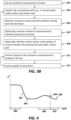
- FIG. 4 is a simplified schematic plot of resistance with time, according to some embodiments of the disclosure.
- FIG. 4 illustrates detected resistance between a joining tool (e.g., joining tool 216) and a pad (e.g., pad 210a) to which the joining tool is establishing a connection. Where the resistance may be detected at the electrode as the "electrode resistance”.
- detected resistance is high, for example, associated with electrically insulating material (e.g., air) between the joining tool and pad.
- electrically insulating material e.g., air
- detected resistance may drop 401 until contact is made at 402 between the pad and joining tool.
- a slope of the drop 401 and a lower resistance detected e.g., below a threshold resistance and/or below a proportion of the initial resistance detected
- Heating of the joining tool during time period 404 may increase resistance detected, the increase, e.g., associated with increase in temperature of the flexible circuit strip.
- heating of the joining tool may be controlled during time period 404 e.g., to maintain the resistance, R, below a threshold.
- resistance R when the connection is established resistance R may drop.
- a desired drop in resistance e.g., as illustrated at 406
- heating of the joining tool is ceased once the desired drop in resistance is identified.
- a peak resistance is identified, the value of which being used to determine the desired drop, which may be a given resistance or proportion of the peak resistance.
- the desired drop is identified as resistance reaching (e.g., falling to) a given value after the identified peak.
- a final resistance detected 408 after heating (and optionally cooling) is used to assess quality of the connection.
- quality of the connection is verified when resistance detected is lower than a threshold and/or a proportion and/or value lower than that resistance detected prior 402 to performing the heat joining process.
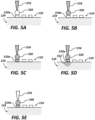
- FIGs. 5A-E are simplified schematics illustrating establishing electrical connection to a pad 210a using a joining tool 216, according to some embodiments of the disclosure.
- FIGs. 5A-E illustrate a portion of a flexible circuit strip 124 e.g., the same portion during establishing of electrical connection to pad 210a.
- higher temperatures and/or heating is illustrated in FIGs. 5A-E by shading.
- joining tool 216 e.g., a tip of the joining tool
- the joining tool is then heated, e.g., illustrated in FIG. 5A by shading of joining tool 216.
- heat from joining tool 216 has conducted to wire 550 raising the temperature of wire 550.
- heating of the wire 550 is sufficient to connect the wire to the pad via welding.
- heating of joining tool 216 continues, e.g., as illustrated in FIG. 5C where heat has been conducted to pad 210a raising the temperature of the pad. In some embodiments, this heating of both the wire and pad is sufficient to connect the wire to the pad via welding.
- the joining tool 216 is a soldering iron. Where one or both of the pad and wire may include solder and/or where solder may be positioned in contact with one or more of the pad, the joining tool, and the wire. The joining tool may contact one or more of the pad, wire, and solder material. Heating of the joining tool may then melt the solder to connect the pad and wire.
- heat has conducted from pad 210a to an upper portion 552 of flexible circuit strip 124 raising its temperature.
- raising of temperature of the upper layer of flexible circuit strip 124 e.g., adjacent to portion 552 may extend to pads neighboring pad 210a.
- this situation is avoided and/or temperature of the flexible circuit strip is maintained under a temperature at which damage occurs to flexible circuit strip 124 by sporadic (e.g., switched) heating of the joining tool.
- Switching potentially prevents over-heating of the flexible circuit strip material where the material is thermally insulating (e.g., in contrast with the pad material).
- joining tool heating is stopped e.g., power to heating element/s of the joining tool is cut e.g., as illustrated in FIG. 5E .
- the joining tool may be repetitively heated e.g., cycling to heat wire 550 and/or pad 210a to temperature/s associated with a good quality connection without damaging the flexible circuit strip.
- Range format should not be construed as an inflexible limitation on the scope of the present disclosure. Accordingly, descriptions including ranges should be considered to have specifically disclosed all the possible subranges as well as individual numerical values within that range. For example, description of a range such as from 1 to 6 should be considered to have specifically disclosed subranges such as from 1 to 3, from 1 to 4, from 1 to 5, from 2 to 4, from 2 to 6, from 3 to 6 etc., as well as individual numbers within the stated range and/or subrange, for example, 1, 2, 3, 4, 5, and 6. Whenever a numerical range is indicated within this document, it is meant to include any cited numeral (fractional or integral) within the indicated range.
- Example 1 A method of electrically connecting a wire (550) to a connection pad (210a) of a flexible circuit strip (124) using a heat joining tool (216), wherein the flexible circuit strip includes a polymer body (214), a plurality of electrodes (126), a plurality of connection pads (110) and a plurality of conductive traces (212), a trace connecting each of the plurality of electrodes (126) to a connection pad of the plurality of connection pads (110), the method comprising:
- Example 2 The method according to Example 1, wherein said activating comprises supplying a plurality of electrical pulses to one or more heating element of said joining tool.
- Example 3 The method according to Example 2, wherein said plurality of electrical pulses are voltage supply pulses to said one or more heating element.
- Example 4 The method according to any one of Examples 2-3, wherein said controlling comprises controlling one or more features of said plurality of electrical pulses.
- Example 5 The method according to Example 4, wherein said one or more features of said plurality of electrical pulses comprises one or more of: a pulse duration, a pulse repetition frequency, and a pulse amplitude.
- Example 7 The method according to any one of Examples 1-4, wherein said controlling comprises maintaining said resistance above a lower threshold.
- Example 8 The method according to any one of Examples 2-7, comprising determining a rate of change of said resistance; wherein said controlling is using said rate of change.
- Example 9 The method according to Example 8, wherein said determining comprises determining that said rate of change of said resistance is below a threshold; and wherein said controlling comprises increasing an amplitude of said electrical power pulses.
- Example 10 The method according to any one of Examples 2-9, wherein said controlling comprises:
- Example 11 The method according to Example 10, comprising deactivating said joining tool (216) upon detecting said drop in said portion of said resistance.
- Example 12 The method according to Example 11, wherein said detecting said drop in said resistance occurs during said supplying of a pulse of said plurality of electrical pulses.
- Example 13 The method according to Example 10, comprising:
- Example 14 The method according to any one of Examples 10-13, comprising assessing a quality of connection between said wire (550) and said connection pad (210a) based on said drop in said resistance.
- Example 15 The method according to Example 14, wherein said quality is a quality of one or more of thermal, electrical, and mechanical connection between said wire and said connection pad.
- Example 16 The method according to any one of Examples 14-15, comprising repeating said activating based on said assessing.
- Example 17 The method according to any one of Examples 14-16, comprising adjusting one or more features of said supplying based on said assessing.
- Example 18 A system for electrically connecting a wire (550) to a connection pad (210a) of a flexible circuit strip (124) including a polymer body (214), a plurality of electrodes (126), a plurality of connection pads (110) and a plurality of conductive traces (212), a trace connecting each of the plurality of electrodes (126) to a connection pad of the plurality of connection pads (110) comprising:
- Example 19 A controller (218) for controlling electrically connecting of a wire (550) to a connection pad (210a) of a flexible circuit strip (124) using a heat joining tool (216), wherein the flexible circuit strip (124) includes a polymer body (214), a plurality of electrodes (126), a plurality of connection pads (110) and a plurality of conductive traces (212), a trace connecting each of the plurality of electrodes (126) to a connection pad of the plurality of connection pads (110), which controller (218) comprising circuitry configured to:
Landscapes
- Engineering & Computer Science (AREA)
- Health & Medical Sciences (AREA)
- Microelectronics & Electronic Packaging (AREA)
- Heart & Thoracic Surgery (AREA)
- Life Sciences & Earth Sciences (AREA)
- Biomedical Technology (AREA)
- Animal Behavior & Ethology (AREA)
- General Health & Medical Sciences (AREA)
- Public Health (AREA)
- Veterinary Medicine (AREA)
- Manufacturing & Machinery (AREA)
- Cardiology (AREA)
- Nuclear Medicine, Radiotherapy & Molecular Imaging (AREA)
- Mechanical Engineering (AREA)
- Radiology & Medical Imaging (AREA)
- Vascular Medicine (AREA)
- Surgery (AREA)
- Plasma & Fusion (AREA)
- Otolaryngology (AREA)
- Physics & Mathematics (AREA)
- Medical Informatics (AREA)
- Molecular Biology (AREA)
- Electric Connection Of Electric Components To Printed Circuits (AREA)
- Biophysics (AREA)
- Pulmonology (AREA)
- Anesthesiology (AREA)
- Hematology (AREA)
- Surgical Instruments (AREA)
Abstract
A method of electrically connecting a wire to a connection pad of a flexible circuit strip using a heat joining tool, wherein the flexible circuit strip includes a polymer body, a plurality of electrodes, a plurality of connection pads and a plurality of conductive traces, a trace connecting each of the plurality of electrodes to a connection pad of the plurality of connection pads, the method including: positioning the joining tool in proximity to a connection pad of the plurality of connection pads and a wire to be connected to the connection pad; activating the joining tool to heat a tip of the joining tool to electrically connect the wire to the connection pad; monitoring, during the activating, a resistance between the joining tool and an electrode electrically connected to the connection pad, which resistance indicative of temperature of the flexible circuit strip; and controlling the activating to maintain the resistance below an upper threshold associated with the flexible circuit strip reaching a damaging temperature.
Description
- This application claims priority from
U.S. Provisional Application No. 63/603,144, filed on 28 November 2023 - The present disclosure, in some embodiments thereof, relates to catheter manufacture and, more particularly, but not exclusively, to establishing electrical connections to a flexible circuit strip of the catheter.
- A wide range of medical procedures involve placing probes, such as catheters, within a patient's body. Electrode catheters have been in common use in medical practice for many years. They are used to stimulate and map electrical activity in the heart and to ablate sites of aberrant electrical activity.
- A wall cavity of an organ of a patient, such as a cardiac cavity, can be mapped and/or ablated using a catheter having multiple electrodes fitted at an expandable distal end assembly of the catheter. The expandable distal-end assembly is coupled at a distal end of a catheter shaft for insertion into the cavity. The expandable distal end assembly may be shaped in the form of a balloon, basket and/or another type of cage and may include a plurality of electrodes configured for sensing and/or delivering therapeutic signals.
- In order to better understand the subject matter that is disclosed herein and to exemplify how it may be carried out in practice, embodiments will now be described, by way of non-limiting example only, with reference to the accompanying drawings, in which:
-
FIG. 1A is a schematic view of a basket catheter, according to some embodiments of the disclosure; -
FIG. 1B is a simplified schematic of flexible polymer circuit strips, according to some embodiments of the disclosure; -
FIG. 2 is a simplified schematic of a system for establishing electrical connections to a flexible circuit strip, according to some embodiments of the disclosure; -
FIG. 3A is a method of establishing a connection to a workpiece, according to some embodiments of the disclosure; -
FIG. 3B is a method of establishing a connection to a workpiece, according to some embodiments of the disclosure; -
FIG. 4 is a simplified schematic plot of resistance with time, according to some embodiments of the disclosure; and -
FIGs. 5A-E are simplified schematics illustrating establishing electrical connection to a pad using a joining tool, according to some embodiments of the disclosure. - In some embodiments, although non-limiting, like elements are referred to using like numerals.
- The present disclosure, in some embodiments, thereof, relates to catheter manufacture and, more particularly, but not exclusively, to establishing electrical connections to a flexible circuit strip of the catheter.
- Some catheters, such as basket catheters, may have many (e.g., 30-100) electrodes mounted on a plurality of splines of the basket, which is coupled through a shaft of the catheter to a connector at the proximal end of the shaft. In some embodiments, the electrodes may be hosted by a plurality of flexible printed circuit boards (PCB) each of which is mounted on a spline of the basket. Both the flexible PCBs, also herein termed "flexible circuit strip" on the splines and a PCB of the connector have pads and a plurality of wires, e.g., a wire for each electrode, running through the shaft, provides electrical coupling. The distal end of each wire is coupled to a predefined pad on the spline, and a proximal end of each wire is coupled to a corresponding pad in the connector, so as to exchange electrical signals between the electrodes and a control console, e.g., a PIU (patient interface unit) of the catheter, via the shaft. Due to the limited real estate on the splines, the pads are required to cover a small area. For example, the pad size, (e.g., pad surface area) may be in the order of magnitude of tens of micrometers squared, (also referred to herein as microns squared) for each pad on the printed circuit board, resulting in a potentially time-consuming and/or costly coupling process between the wires and the respective pads. Pads may also be placed close to one another e.g., spacing between pads being less than pad length and/or width and/or where there is less than 0.1-0.5 mm between adjacent pads. The pads may densely occupy an area on the flexible circuit strip, where, for example, a proportion of the surface area occupied by pads is 20-50%.
- In manufacture, heat joining (e.g., soldering or welding) of the many wires to the many pads of a flexible circuit strip (e.g., sequentially), e.g., involving repeated heating of wires and pads, may increase temperature of the flexible circuit strip e.g., to a level at which material of the strip (e.g., a polymer body of the flexible circuit strip) suffers damage. Associated, for example, with repeated heating for connection of multiple pads, heat applied to connect a wire to one pad may lead to undesired heating of another neighboring pad that has already been connected to a wire e.g., further affecting the polymer body around the previously connected and heated pad and/or potentially degrading a quality of connection which as already been established.
- A broad aspect of some embodiments of the disclosure relates to monitoring resistance between a joining tool connecting a wire to a pad and an electrode corresponding to the pad. The resistance and/or changes to the resistance over time potentially providing an indication as to temperature of the flexible polymer strip, e.g., where increasing resistance generally indicates increasing temperature. For example, as resistance detected includes that of the pad, the electrode, and the tracing connecting the pad and electrode, each of which may be affected by temperature.
- An aspect of some embodiments of the disclosure relates to establishing electrical connection to a pad of a flexible circuit strip using a joining tool where heating of the joining tool for forming of the connection is controlled using detected resistance between the joining tool and an electrode connected to the pad.
- In some embodiments, the flexible circuit strip includes material which is heat-sensitive (e.g., includes polymer). Heat-sensitivity may be manifested as deformation and/or chemical change/s to the material by exposure to temperatures over a threshold and/or raised temperatures for longer than a threshold duration of time.
- The resistance detected is potentially indicative of temperature of the polymer body of the flexible polymer strip, which may be prone to increasing in temperature during the connection process, the increase associated with thermally insulating nature of the polymer material e.g., in comparison to the electrical components.
- In some embodiments, the flexible circuit strip includes a plurality of pads, and the establishing is of a plurality of connections to each of the plurality of pads, for example, sequentially and/or by a single joining tool.
- In some embodiments, the pads are closely packed and/or directly disposed on the heat-sensitive material e.g., the polymer body. In some embodiments, electrical circuitry connected to the pads (e.g., trace and electrode for each pad) conduct heat from the pads to other regions of the flexible circuit strip, heat at the pad potentially increasing temperature of polymer portions elsewhere e.g., adjacent to trace/s and/or electrode/s.
- In some embodiments, heating of the joining tool during the joining process is non-continuous. Where, for example, a power supply to heating elements is a pulsed power supply (e.g., including voltage pulses). Without wanting to be bound by theory, it is theorized that the cycles of heating and cooling enable heating of the elements which are to be connected (e.g., one or more of the pad, wire to be connected to the pad, and solder material) to rise to temperatures suitable for establishing connection while heat-sensitive portion/s of the flexible circuit strip remain below a temperature at which damage may occur. It is theorized that high thermal conductivity of the element/s (e.g., metal) being connected as compared to low thermal conductivity of other portion/s of the flexible circuit strip (e.g., polymer) enable cycles of heating and cooling to raise temperature of the element/s to be connected while minimally raising temperature of the heat-sensitive portions.
- In some embodiments, one or more feature of the pulsed power supply is controlled using resistance levels detected. For example, where the feature/s include one or more of pulse duration (width), amplitude, and temporal pattern (e.g., frequency). In some embodiments, control of pulsed power supply to the heating element/s is by pulse width modulation (PWM). In some embodiments, resistance is detected during the joining process e.g., providing feedback for control of the power supply to the heating element/s during the joining process.
- In some embodiments, the control is to maintain the resistance below an upper threshold resistance, for example, where the upper threshold resistance is associated with damaging temperatures for the flexible circuit strip.
- In some embodiments, the control is to ensure quality of the joining process (e.g., quality of the heating). Where, if the quality of heating is identified as being low, power supply (e.g., amplitude of voltage pulses to the heating element/s) is increased. In some embodiments, quality of the joining process is ensured by maintaining the resistance above a lower threshold resistance, for example, where the threshold is associated with temperatures for which the joining process is efficient and/or effective. Alternatively or additionally, in some embodiments, quality of the joining process is ensured by maintaining a rate of change of resistance during heating (e.g., during a power supply pulse) above a threshold rate.
- In some embodiments, the threshold/s are determined by detecting of levels of resistance at different flexible circuit strip temperatures, for example, for a plurality of flexible circuit strips and/or electrodes and pads thereof. Where, in some embodiments, average values are used to determine the threshold/s.
- In some embodiments, resistance is additionally detected between the joining tool and the pad which is being connected. In some embodiments, this "pad resistance" is used to determine a portion of (e.g., sum portion of) the "electrode resistance" (resistance detected between the joining tool and electrode) which is associated with temperature of the flexible circuit strip, independent of the pad. In some embodiments, the pad resistance is monitored during the joining process where both types of resistance detected are used in control of the power supply to the heating elements. Alternatively, in some embodiments, pad resistance is detected during a data collection process e.g., as described above regarding determining thresholds. Where, in some embodiments, the thresholds are determined using both types of resistance, but where the thresholds themselves correspond to the electrode resistance only.
- An aspect of some embodiments of the disclosure relates to identifying when a sufficient quality electrical and/or mechanical connection has been established between a pad and wire. Where, upon the identifying, heating of the joining tool may be stopped. A potential advantage of accurate and/or early identification of establishment of a sufficiently good connection enables a reduced duration of heating and/or reduced heating temperature.
- In some embodiments, from one or both of the pad resistance and the electrode resistance, a drop in resistance is identified. Where the drop is associated with establishment of the connection e.g., and not with cooling. For example, where, in some embodiments, the drop is identified during a power supply pulse to the heating element/s of the joining tool.
- Alternatively, or additionally, in some embodiments, an initial resistance detected (pad and/or electrode) before an initial activation of the joining tool is compared to a resistance detected after a joining process and after the flexible circuit strip has cooled to an initial temperature. Where the drop in resistance is identified in this comparison. In some embodiments, if this drop is insufficient, the joining process may be repeated e.g., to increase mechanical and/or electrical quality of the connection.
- Before explaining at least one embodiment of the invention in detail, it is to be understood that the invention is not necessarily limited in its application to the details of construction and the arrangement of the components and/or methods set forth in the following description and/or illustrated in the drawings and/or the Examples. The invention is capable of other embodiments or of being practiced or carried out in various ways.
-
FIG. 1A is a schematic view of abasket catheter 111 according to some embodiments of the disclosure. - The
basket catheter 111 includes an elongateddeflectable element 112 having adistal end 114, acoupler 116 connected to thedistal end 114, and anoptional pusher 118. Theoptional pusher 118 is configured to be advanced and retracted through thedeflectable element 112, for example, using a manipulator or handle (not shown). Thebasket catheter 111 also includes anexpandable assembly 122 comprising a plurality of flexible circuit strips 124 (only some labeled for the sake of simplicity) also herein termed "flexible splines". Where, in some embodiments, the flexible circuit strips 124 are polymer circuit strips. Eachflexible circuit strip 124 includesmultiple electrodes 126 disposed thereon (only some labeled for the sake of simplicity). The formation of the various elements and how they are connected with each other are described in more detail in US Patent Application Publication No.US 2021/0187241 . - In some embodiments, form and/or structure of
basket catheter 111 is provided by a basket structure, which in some embodiments, includes (e.g., is formed of) nitinol e.g., including a plurality of nitinol strips (also herein termed "splines"). Where a least a portion of flexible circuit strips 124 are each supported by a corresponding nitinol strip. In some embodiments, strips of the nitinol basket structure are connected together e.g., at a proximal end ofbasket catheter 111. Flexible circuit strips 124 may be mounted to the nitinol basket structure prior to or after establishing electrical connections to the pads (e.g.,pads 110FIG. 1B ) of flexible circuit strips 124. In some embodiments, electrical connections topads 110 of flexible circuit strips 124 are established when the flexible circuit strips 124 are in a flat and/or un-disconnected configuration e.g., the configuration illustrated inFIG. 1B , prior or after connecting of the flexible circuit strips to the nitinol support structure. -
FIG. 1B is a top view of flexible polymer circuit strips 124 prior to their assembly for use in the basket catheter ofFIG. 1A . - Reference is now made to
FIG. 1B , which is a schematic view of the flexible polymer circuit strips 124 for use in thebasket catheter 111 ofFIG. 1A . The flexible polymer circuit strips 124 may be formed from a single piece of polymer, such as polyimide. Circuit strips 124 may be connected to each other by polyimide, or assembled as individual pieces that are held in proper alignment and secured to coupler 116FIG. 1A . By manufacturing circuit strips 124 as individual components the yield of the base circuit may be increased as a failed electrode scraps one circuit strip rather than an entire assembly of strips. Respective first ends 142 of the respective flexible polymer circuit strips 124 include anelectrical connection array 160. - An inset 162 shows that the
electrical connection array 160 includespads 110 thereon (only some labeled for the sake of simplicity). Thepads 110 are connected via traces (not shown), optionally located on the back of the flexible polymer circuit strips 124, to respective ones of theelectrodes 126 disposed on the front of the flexible circuit strips 124. Away from the region of the first ends 142, the flexible circuit strips 124 are separate from each other to allow the flexible circuit strips 124 to form the expandable assembly 122 (FIG. 1A ) when connected to thebasket catheter 111. Wires (not shown) may connect theelectrodes 126 to control circuitry (not shown) viapads 110. The wires may be disposed in lumens (not illustrated) of the elongated deflectable element 112 (FIG. 1A ). - The flexible circuit strips 124 may have any suitable dimensions. For example, the length of the flexible circuit strips 124 may be in the range of 10 mm to 60 mm, e.g., 30 mm, the width of the flexible circuit strips 124 may be in the range of 0.25 mm to 3 mm, e.g., 0.72 mm, the thickness of the flexible circuit strips 124 may be in the range of 0.005 mm to 0.14 mm.
- In some embodiments,
electrodes 126 extend to occupy a majority of the width of the flexible circuit strips 124 by which they are hosted. Where, in some embodiments,electrode width 192 is 0.25-3 mm, and/orelectrode length 190 is 0.25-3 mm. - In some embodiments, one or more pad dimensions are smaller than electrode dimensions. Where the surface area the pad presents for contact (e.g., to a measurement probe or joining tool) is smaller than that presented by the electrodes. For example, a pad upper surface area being 1-20% of that of the electrodes. For example, a
pad width 194 being 0.05-0.5 mm, and/or apad length 196 0.1-1 mm. - A surface area 162 of the flexible circuit strips 124 on which
pads 142 are disposed may be small and/or the density of pads on the area may be high. For example, the area having awidth 178 of 0.25-3 mm and alength 198 of 0.5-6 mm and/or the proportion of the surface area occupied by pads is 20-50%. -
FIG. 2 is a simplified schematic of asystem 200 for providing electrical connections to aflexible circuit strip 124, according to some embodiments of the disclosure. - In some embodiments,
flexible circuit strip 124 is a portion of a catheter e.g., having one or more features as illustrated in and/or described regardingcatheter 111FIG. 1A . Where, in some embodiments,flexible circuit strip 124 corresponds to one or more (e.g., each) of the flexible circuit strips 124 ofFIG. 1A and/orFIG. 1B . - In some embodiments,
system 200 includes a joiningtool 216 configured to join an electrical connector e.g., a wire (not illustrated) to each of pads 110 (e.g., one pad at a time). In some embodiments, joiningtool 216 is a heat joining tool which joins by generating and supplying heat to the object/s to be joined e.g., soldering iron, or welding gun, or ultrasonic joining tool. - In some embodiments,
system 200 includes one ormore sensor 220 where sensor/s 220 are resistance sensors. In some embodiments,resistance sensor 220 detects resistance between joiningtool 216 and an electrode (e.g., electrode 126a as illustrated inFIG. 2 ). In some embodiments, aprobe 242 is used to provide electrical contact to the electrode. Optionally, (not illustrated) in some embodiments, resistance is detected directly between joiningtool 216 and apad 210a e.g., by contacting the pad. - In
FIG. 2 , in some embodiments, electrical connections (e.g., for detection of resistance) are illustrated by solid lines, and data connections (e.g., transfer of detected resistance levels to controller 218) are illustrated by dashed lined arrows. - In some embodiments, joining
tool 216 is controlled by acontroller 218 which receives sensor signals from one or more sensor. For example, from one or more of resistance sensor/s 220. - In some embodiments,
controller 218, for example, based on detected resistance levels (e.g., from sensor/s 220) generates control signals for activation of joiningtool 216. In some embodiments,controller 218 generates and sends control signal/s to apower supply 226 of joiningtool 216, where the control signal/s control power supplied by power supply to heating element/s 208. Alternatively or additionally, in some embodiments,controller 218 generates control signal/s which are translated (e.g., by a joining tool) processor into control signals forpower supply 226. - In some embodiments,
power supply 226 is configured to supply pulses of power to heating element/s 208, where, in some embodiments, based on the detected resistance, one or more features of the pulses (e.g., one or more of amplitude, pulse repetition frequency, and pulse duration) are controlled based on the detected resistance. In some embodiments, pulse width modulation (PWM) is used. - Optionally, in some embodiments,
system 200 includes one or more temperature sensor (not illustrated), for example, the joining tool may include a temperature sensor which may provide temperature feedback measurement/s tocontroller 218 for control of temperature of the joining tool. - In some embodiments,
system 200 includes a rigid support (not illustrated) which provides mechanical support toflexible circuit strip 124 e.g., enabling joiningtool 216 to apply pressure to a pad e.g., during a joining process - In some embodiments,
flexible circuit strip 124 has at least one (e.g., a plurality) ofelectrodes 126. Whereelectrodes 126 may be disposed on adistal portion 206 offlexible circuit strip 124.Electrodes 126 may be disposed on an external surface offlexible circuit strip 124 e.g., one or more ofelectrodes 126 may protrude from a generally planar external surface (e.g., a top surface) offlexible circuit strip 124 and/or one or more ofelectrodes 126 may have an electrode top surface flush (or recessed from) theflexible circuit strip 124 top surface. - In some embodiments, a plurality of
pads 110 are disposed on aproximal portion 228 offlexible circuit strip 124. In some embodiments, one or more ofelectrodes 126 e.g., each electrode, is electrically connected to a corresponding pad of plurality ofpads 110 e.g., each electrode to a pad by anindividual trace 212,flexible circuit strip 124 including a plurality oftraces 212. In some embodiments, the electrical connections (e.g., traces or wires) extend through abody 214 offlexible circuit strip 124. - In some embodiments,
flexible circuit strip 124 includes a plurality of layers where, for example,wires 212 connectingpads 110 toelectrodes 126 are sandwiched between at least two layers. Where, in some embodiments, anouter surface 252 of flexible circuit strip 124 (also herein termed "top surface" 252) hostspads 110 andelectrodes 126. In some embodiments,top surface 252 includes electrically insulating material (e.g., portions which are not the pads or electrodes are formed of polymer). - Alternatively, or additionally, in some embodiments, the traces are disposed on a
back surface 254 of flexible circuit strip, where, for example, connectors extend throughbody 214 to connect pads and electrodes to respective traces. Where backsurface 254, in some embodiments, is a surface ofbody 214 generally opposingtop surface 252. - In some embodiments, joining
tool 216 is automatically moveable with respect to flexible circuit strip 124 (e.g., by one or more actuators/s) for moving the joining tool between locations of the plurality of pads. Where, in some embodiments, one or both of joiningtool 216 and the support on which the flexible circuit strip is disposed are moveable with respect to each other. In some embodiments, positioning of joiningtool 216 with respect to the flexible circuit strip 123 is controlled bycontroller 218. - In some embodiments, the joining
tool tip 238 includes an outer surface e.g., a cover including material which is highly electrically and/or thermally conductive and/or heat resistant. For example, the joining tool including a cover configured to cover (e.g., surround) at least a portion of joiningtool 216 between a region of electrical contact between resistance sensor/s 220 and joiningtool 216. In some embodiments, (e.g., as associated with high electrical and/or thermal conductivity) resistive and/or capacitive properties of the joining tool have low dependence on temperature. - In some embodiments, at least a portion of the joining tool which contacts a pad (e.g.,
tip 238 and/or a portion of the tip) during establishing connection to the pad is non-adhesive to material ofpads 110. For example, at temperatures employed during establishing of connections to pads. When the joining tool is a soldering iron, material of the joining tool which contacts solder may be non-adhesive to solder e.g., alternatively or additionally to being non-adhesive to the pad surface. - In some embodiments, the joining tool tip and/or cover and/or region of the joining tool in an electrical path between the joining tool and sensor/
s 208, includes (e.g., is formed of) gold. - In some embodiments, user instructions (e.g., to initiate the joining process) are received through and/or information is displaced to a user through one or more user interface (UI) 236. Where, in some embodiments, data is transferred between
UI 236 andcontroller 218. For example, in some embodiments, user instructions are transferred byUI 236 tocontroller 218 which, in some embodiments, controls operation ofsystem 200 based on the user instructions. One or more UI may be local to joiningtool 216 and/or other system components and/or one or more UI may be located remotely. - Optionally, in some embodiments, external processing and/or
memory circuitry 234 communicates withUI 236 and/orcontroller 218. For example,circuitry 234 enabling remote control ofsystem 200 e.g., via remote UI/s. -
FIG. 3A is a method of establishing a connection to a workpiece, according to some embodiments of the disclosure. - At 304, in some embodiments, resistance between the joining tool and the electrode is detected.
- At 306, in some embodiments, activation and/or temperature of the joining tool is controlled based on the detected resistance level/s. In an exemplary embodiment, activation of the joining tool is controlled by controlling power supplied to heating element/s of the joining tool.
- In some embodiments, heating of the joining tool during the joining process is non-continuous. Where, for example, a power supply to heating elements is a pulsed power supply (e.g., including voltage pulses).
- In some embodiments, one or more feature of the pulsed power supply is controlled using the detected resistance. For example, where the feature/s include one or more of pulse duration (width), amplitude, and temporal pattern (e.g., frequency). In some embodiments, control of pulsed power supply to the heating element/s is by pulse width modulation (PWM). In some embodiments, the resistance is detected during the joining process e.g., providing feedback for control of the power supply to the heating element/s during the joining process.
- In some embodiments, the control is to maintain the resistance below an upper threshold resistance, for example, where the threshold is associated with the flexible circuit strip reaching damaging temperatures.
- Optionally, in some embodiments, the control is to ensure quality of the joining process (e.g., quality of the heating). Where, if the quality of heating is identified as being low, power supply (e.g., voltage e.g., amplitude of voltage pulses to the heating element/s) is increased. In some embodiments, quality of the joining process is ensured by maintaining the resistance above a lower threshold resistance, for example, where the threshold is associated with temperatures for which the joining process is efficient and/or effective. Alternatively or additionally, in some embodiments, quality of the joining process is ensured by maintaining a rate of change of resistance during heating (e.g., during a power supply pulse) above a threshold rate.
- In some embodiments, the threshold/s are received e.g., from a memory (e.g., of circuitry 234). In some embodiments, the threshold/s are provided by a user e.g., thorough a user interface. In some embodiments, the thresholds are determined by detecting resistance while heating the flexible circuit strip to different temperatures. For example, detecting resistance levels at different flexible circuit strip temperatures, for example, for a plurality of flexible circuit strips and/or electrodes and pads thereof. In some embodiments, averages are used to determine the threshold/s.
-
FIG. 3B is a method of establishing a connection to a workpiece, according to some embodiments of the disclosure. - At 301, in some embodiments, resistance measurement circuitry is set up. For example, where a measurement probe is brought into contact with an electrode corresponding to the pad (e.g.,
probe 242,electrode 126a, andpad 210a,FIG. 2 ). In some embodiments, resistance measurement circuitry has fixed position e.g., connection to the electrode for determining resistance being provided by a jig where, for example, positioning the flexible circuit strip for the electrical connection process sets up the resistance measurement circuitry. - At 303, in some embodiments, a tip of a joining tool (e.g., 238 tip of joining
tool 216FIG. 2 ) is brought into proximity (e.g., contact with) a pad and/or a wire to be connected to the pad and/or solder (e.g., where the joining tool is a soldering iron). In some embodiments, the proximity is sufficient for enough heat to be conducted from the joining tool to the pad and/or wire and/or solder for the connecting process e.g., melting of soldier and/or pad and/or wire material. In some embodiments, positioning of the joining tool is an automated process, for example where one or more actuator controlled by a controller (e.g.,controller 218FIG. 2 ) is configured to move the joining tool with respect to the flexible circuit strip. - At 305, in some embodiments, electrode resistance is monitored. For example, according to one or more feature of
step 300FIG. 3A . - At 307, optionally, in some embodiments, resistance is additionally monitored between the joining tool and the pad which is being connected. In some embodiments, this "pad resistance" is used to determine a portion of the "electrode resistance" (resistance detected between the joining tool and electrode at step 305) which is associated with temperature of the trace and electrode, independent of the pad e.g., indicative of the temperature of the flexible circuit strip.
- In some embodiments, both resistances are monitored during the joining process and used in control of the power supply to the heating elements.
- Alternatively, in some embodiments, pad resistance is detected during a data collection process e.g., as described in
step 302 determining thresholds. In some embodiments, the thresholds are determined from data collection of both types of resistance detected, but detected electrode resistance level/s (e.g., only) are used during the joining process. - At 309, optionally, in some embodiments, the detected electrode and/or pad resistances are used to identify contact between the joining tool and pad and/or verify that quality of the contact is sufficient. Where, in some embodiments, contact is identified as a drop in resistance (e.g., slope of the drop in resistance being above a threshold) detected and/or as the resistance detected falling to below a threshold.
- If contact is not verified and/or quality of the contact is not verified (e.g., resistance detected is higher than a threshold) the tip may be repositioned e.g., returning to step 303. Where, for example, the tip may be moved towards the pad e.g., to increase pressure between the pad and the tip to improve electrical and/or thermal contact therebetween.
- At 311, in some embodiments, heating of the joining tool tip is controlled, using the detected resistance. Where the electrode resistance may be used, e.g., according to one or more feature of
step 302FIG. 3A and, optionally, where pad resistance may be additionally used. - At 313, in some embodiments, a quality of connection between the wire and pad is assessed using detected resistance. For example, in some embodiments, a drop in resistance is identified in one or both of the pad resistance and the electrode resistance. The drop may be associated with establishment of electrical connection e.g., and not with cooling. For example, where, in some embodiments, the drop is identified during a power supply pulse to the heating element/s of the joining tool. In some embodiments, a drop is identified when solder and/or the wire form part of the circuitry for which resistance is being detected. Without wanting to be bound by theory, it is theorized that melting of the soldier and/or wire to the pad e.g., associated with improving electrical connection therebetween, reduces resistance from the joining tool through the pad.
- Optionally, in some embodiments, upon the identifying, heating of the joining tool may be stopped. A potential advantage of accurate and/or early identification of establishment of a sufficiently good connection enables a reduced duration of heating and/or reduced heating temperature.
- Alternatively, or additionally, in some embodiments, an initial resistance (pad and/or electrode) detected at an initial temperature and before activation of the joining tool is compared to a detected resistance after a joining process and after the flexible circuit strip has cooled to an initial temperature. Where the drop in resistance is identified in this comparison. In some embodiments, if this drop is insufficient, the joining process may be repeated e.g., to increase mechanical and/or electrical quality of the connection.
-
FIG. 4 is a simplified schematic plot of resistance with time, according to some embodiments of the disclosure. - In some embodiments,
FIG. 4 illustrates detected resistance between a joining tool (e.g., joining tool 216) and a pad (e.g.,pad 210a) to which the joining tool is establishing a connection. Where the resistance may be detected at the electrode as the "electrode resistance". - Where, initially at 400, prior the joining tool contacting the pad, detected resistance is high, for example, associated with electrically insulating material (e.g., air) between the joining tool and pad.
- As the joining tool approaches the pad, detected resistance may drop 401 until contact is made at 402 between the pad and joining tool. Where one or both of a slope of the
drop 401 and a lower resistance detected (e.g., below a threshold resistance and/or below a proportion of the initial resistance detected) are used to identify and/or verify contact between the joining tool and pad. - Heating of the joining tool during
time period 404 may increase resistance detected, the increase, e.g., associated with increase in temperature of the flexible circuit strip. In some embodiments, for example, as described in method/s ofFIG. 3A and/orFIG. 3B , heating of the joining tool may be controlled duringtime period 404 e.g., to maintain the resistance, R, below a threshold. - In some embodiments, when the connection is established resistance R may drop. Where a desired drop in resistance e.g., as illustrated at 406, in some embodiments, is associated with establishment of a good solder connection. In some embodiments, heating of the joining tool is ceased once the desired drop in resistance is identified. Where, in some embodiments, a peak resistance is identified, the value of which being used to determine the desired drop, which may be a given resistance or proportion of the peak resistance. In some embodiments, the desired drop is identified as resistance reaching (e.g., falling to) a given value after the identified peak.
- In some embodiments, a final resistance detected 408 after heating (and optionally cooling) is used to assess quality of the connection. Where, in some embodiments, quality of the connection is verified when resistance detected is lower than a threshold and/or a proportion and/or value lower than that resistance detected prior 402 to performing the heat joining process.
-
FIGs. 5A-E are simplified schematics illustrating establishing electrical connection to apad 210a using a joiningtool 216, according to some embodiments of the disclosure. - Where, in some embodiments,
FIGs. 5A-E illustrate a portion of aflexible circuit strip 124 e.g., the same portion during establishing of electrical connection to pad 210a. In some embodiments, higher temperatures and/or heating is illustrated inFIGs. 5A-E by shading. - Referring now to
FIG. 5A , in some embodiments, joining tool 216 (e.g., a tip of the joining tool) is brought into contact with apad 210a and/or is brought into contact withwire 550 which is in contact withpad 210a. The joining tool is then heated, e.g., illustrated inFIG. 5A by shading of joiningtool 216. InFIG. 5B , heat from joiningtool 216 has conducted to wire 550 raising the temperature ofwire 550. In some embodiments, heating of thewire 550 is sufficient to connect the wire to the pad via welding. - In some embodiments, heating of joining
tool 216 continues, e.g., as illustrated inFIG. 5C where heat has been conducted to pad 210a raising the temperature of the pad. In some embodiments, this heating of both the wire and pad is sufficient to connect the wire to the pad via welding. - In some embodiments, the joining
tool 216 is a soldering iron. Where one or both of the pad and wire may include solder and/or where solder may be positioned in contact with one or more of the pad, the joining tool, and the wire. The joining tool may contact one or more of the pad, wire, and solder material. Heating of the joining tool may then melt the solder to connect the pad and wire. - Referring now to
FIG. 5D , heat has conducted frompad 210a to anupper portion 552 offlexible circuit strip 124 raising its temperature. With continued heating, raising of temperature of the upper layer offlexible circuit strip 124 e.g., adjacent toportion 552 may extend topads neighboring pad 210a. - In some embodiments, this situation is avoided and/or temperature of the flexible circuit strip is maintained under a temperature at which damage occurs to
flexible circuit strip 124 by sporadic (e.g., switched) heating of the joining tool. Switching potentially prevents over-heating of the flexible circuit strip material where the material is thermally insulating (e.g., in contrast with the pad material). Where, for example, prior to reaching the situation illustrated inFIG. 5D , joining tool heating is stopped e.g., power to heating element/s of the joining tool is cut e.g., as illustrated inFIG. 5E . Where, in some embodiments, the joining tool may be repetitively heated e.g., cycling toheat wire 550 and/orpad 210a to temperature/s associated with a good quality connection without damaging the flexible circuit strip. - As used within this document, the term "about" refers to±20%
- The terms "comprises", "comprising", "includes", "including", "having" and their conjugates mean "including but not limited to".
- The term "consisting of" means "including and limited to".
- As used herein, singular forms, for example, "a", "an" and "the" include plural references unless the context clearly dictates otherwise.
- Within this application, various quantifications and/or expressions may include use of ranges. Range format should not be construed as an inflexible limitation on the scope of the present disclosure. Accordingly, descriptions including ranges should be considered to have specifically disclosed all the possible subranges as well as individual numerical values within that range. For example, description of a range such as from 1 to 6 should be considered to have specifically disclosed subranges such as from 1 to 3, from 1 to 4, from 1 to 5, from 2 to 4, from 2 to 6, from 3 to 6 etc., as well as individual numbers within the stated range and/or subrange, for example, 1, 2, 3, 4, 5, and 6. Whenever a numerical range is indicated within this document, it is meant to include any cited numeral (fractional or integral) within the indicated range.
- It is appreciated that certain features which are (e.g., for clarity) described in the context of separate embodiments, may also be provided in combination in a single embodiment. Where various features of the present disclosure, which are (e.g., for brevity) described in a context of a single embodiment, may also be provided separately or in any suitable sub-combination or may be suitable for use with any other described embodiment. Features described in the context of various embodiments are not to be considered essential features of those embodiments, unless the embodiment is inoperative without those elements.
- Although the present disclosure has been described in conjunction with specific embodiments thereof, it is evident that many alternatives, modifications, and variations will be apparent to those skilled in the art. Accordingly, this application intends to embrace all such alternatives, modifications and variations that fall within the spirit and broad scope of the appended claims.
- All references (e.g., publications, patents, patent applications) mentioned in this specification are herein incorporated in their entirety by reference into the specification, e.g., as if each individual publication, patent, or patent application was individually indicated to be incorporated herein by reference. Citation or identification of any reference in this application should not be construed as an admission that such reference is available as prior art to the present disclosure. In addition, any priority document(s) and/or documents related to this application (e.g., co-filed) are hereby incorporated herein by reference in its/their entirety.
- Where section headings are used in this document, they should not be interpreted as necessarily limiting.
- Following is a non-exclusive list of some exemplary embodiments of the disclosure. The present disclosure also includes embodiments which include fewer than all the features in an example and embodiments using features from multiple examples, even if not listed below.
- Example 1. A method of electrically connecting a wire (550) to a connection pad (210a) of a flexible circuit strip (124) using a heat joining tool (216), wherein the flexible circuit strip includes a polymer body (214), a plurality of electrodes (126), a plurality of connection pads (110) and a plurality of conductive traces (212), a trace connecting each of the plurality of electrodes (126) to a connection pad of the plurality of connection pads (110), the method comprising:
- positioning said joining tool (216) in proximity to a connection pad (210a) of said plurality of connection pads (110) and said wire (550) to be connected to said connection pad (210a);
- activating said joining tool (216) to heat a tip (238) of said joining tool (216) to electrically connect said wire (550) to said connection pad (210a);
- monitoring, during said activating, a resistance between said joining tool (216) and an electrode (126a) electrically connected to said connection pad (210a), which resistance indicative of temperature of said flexible circuit strip (124); and
- controlling said activating to maintain said resistance below an upper threshold associated with said flexible circuit strip (124) reaching a damaging temperature.
- Example 2. The method according to Example 1, wherein said activating comprises supplying a plurality of electrical pulses to one or more heating element of said joining tool.
- Example 3. The method according to Example 2, wherein said plurality of electrical pulses are voltage supply pulses to said one or more heating element.
- Example 4. The method according to any one of Examples 2-3, wherein said controlling comprises controlling one or more features of said plurality of electrical pulses.
- Example 5. The method according to Example 4, wherein said one or more features of said plurality of electrical pulses comprises one or more of:
a pulse duration, a pulse repetition frequency, and a pulse amplitude. - Example 6. The method according to Example 4, wherein said controlling one said one or more feature of said plurality of electrical pulses comprises pulse width modulation (PWM) of an activation signal to said joining tool (216).
- Example 7. The method according to any one of Examples 1-4, wherein said controlling comprises maintaining said resistance above a lower threshold.
- Example 8. The method according to any one of Examples 2-7, comprising determining a rate of change of said resistance;
wherein said controlling is using said rate of change. - Example 9. The method according to Example 8, wherein said determining comprises determining that said rate of change of said resistance is below a threshold; and
wherein said controlling comprises increasing an amplitude of said electrical power pulses. - Example 10. The method according to any one of Examples 2-9, wherein said controlling comprises:
- identifying a portion of said resistance associated with connection between said wire (550) and said connection pad (210a); and
- detecting a drop in said portion of said resistance.
- Example 11. The method according to Example 10, comprising deactivating said joining tool (216) upon detecting said drop in said portion of said resistance.
- Example 12. The method according to Example 11, wherein said detecting said drop in said resistance occurs during said supplying of a pulse of said plurality of electrical pulses.
- Example 13. The method according to Example 10, comprising:
- storing an initial measurement of said resistance prior to said activating when said flexible strip is at an initial temperature;
- deactivating said joining tool (216); and
- wherein said detecting said drop in said resistance comprises comparing said initial measurement of said resistance to a said resistance after said flexible strip has cooled to said initial temperature.
- Example 14. The method according to any one of Examples 10-13, comprising assessing a quality of connection between said wire (550) and said connection pad (210a) based on said drop in said resistance.
- Example 15. The method according to Example 14, wherein said quality is a quality of one or more of thermal, electrical, and mechanical connection between said wire and said connection pad.
- Example 16. The method according to any one of Examples 14-15, comprising repeating said activating based on said assessing.
- Example 17. The method according to any one of Examples 14-16, comprising adjusting one or more features of said supplying based on said assessing.
- Example 18. A system for electrically connecting a wire (550) to a connection pad (210a) of a flexible circuit strip (124) including a polymer body (214), a plurality of electrodes (126), a plurality of connection pads (110) and a plurality of conductive traces (212), a trace connecting each of the plurality of electrodes (126) to a connection pad of the plurality of connection pads (110) comprising:
- a heat joining tool (216) comprising one or more heating element;
- a sensor (220) configured to measure a resistance between said joining tool (216) and an electrode (126a) electrically connected to a connection pad (210a) of said plurality of connection pads (110), which resistance indicative of temperature of said flexible circuit strip (124);
- a controller (218) configured to:
- receive measurements of said resistance from said sensor (220); and
- control activation of said one or more heating element to heat a tip (238) of said joining tool (216) for connecting said connection pad (210a) and a wire (550), in proximity to said tip (238), while maintaining said resistance below an
- upper threshold associated with said flexible circuit strip (124) reaching a damaging temperature.
- Example 19. A controller (218) for controlling electrically connecting of a wire (550) to a connection pad (210a) of a flexible circuit strip (124) using a heat joining tool (216), wherein the flexible circuit strip (124) includes a polymer body (214), a plurality of electrodes (126), a plurality of connection pads (110) and a plurality of conductive traces (212), a trace connecting each of the plurality of electrodes (126) to a connection pad of the plurality of connection pads (110), which controller (218) comprising circuitry configured to:
- activate said joining tool to heat a tip (238) of said joining tool (216) to electrically connect said wire (550) to said connection pad (110a);
- measure, during said activating, a resistance between said joining tool (216) and an electrode (126a) electrically connected to said connection pad (210a), which resistance indicative of temperature of said flexible circuit strip (124); and
- control activation of said joining to maintain said resistance below an upper threshold associated with said flexible circuit strip (124) reaching a damaging temperature.
Claims (15)
- A system for electrically connecting a wire (550) to a connection pad (210a) of a flexible circuit strip (124) including a polymer body (214), a plurality of electrodes (126), a plurality of connection pads (110) and a plurality of conductive traces (212), a trace connecting each of the plurality of electrodes (126) to a connection pad of the plurality of connection pads (110) comprising:a heat joining tool (216) comprising one or more heating element;a sensor (220) configured to measure a resistance between said joining tool (216) and an electrode (126a) electrically connected to a connection pad (210a) of said plurality of connection pads (110), which resistance indicative of temperature of said flexible circuit strip (124);a controller (218) configured to:receive measurements of said resistance from said sensor (220); andcontrol activation of said one or more heating element to heat a tip (238) of said joining tool (216) for connecting said connection pad (210a) and a wire (550), in proximity to said tip (238), while maintaining said resistance below an upper threshold associated with said flexible circuit strip (124) reaching a damaging temperature.
- The system according to claim 1, wherein said controller (218) is configured to control activation by controlling supply of a plurality of electrical pulses to said one or more heating element.
- The system according to claim 2, wherein said plurality of electrical pulses are voltage supply pulses to said one or more heating element.
- The system according to any one of claims 2-3, wherein said controller (218) is configured to control one or more features of said plurality of electrical pulses.
- The system according to claim 4, wherein said one or more features of said plurality of electrical pulses comprises one or more of: a pulse duration, a pulse repetition frequency, and a pulse amplitude.
- The system according to claim 4, wherein said controller (218) is configured to control said one or more features of said plurality of electrical pulses by pulse width modulation (PWM) of an activation signal to said joining tool (216).
- The system according to any one of claims 1-6, wherein said controller (218) is configured to maintain said resistance above a lower threshold.
- The system according to any one of claims 2-7, wherein said controller (218) is configured to:determine a rate of change of said resistance;control said activation of said one or more heating element using said rate of change of said resistance.
- The system according to claim 8, wherein said controller (218) is configured todetermine if said rate of change of said resistance is below a threshold; andcontrol said activation by increasing an amplitude of said plurality of electrical power pulses.
- The system according to any one of claims 2-9, wherein controller (218) is configured to:identify a portion of said resistance associated with connection between said wire (550) and said connection pad (210a);detect a drop in said portion of said resistance; anddeactivate said joining tool (216) when said drop in said portion of said resistance is detected.
- The system according to claim 10, wherein said controller (218) is configured to detect said drop in said resistance occurs during said supply of a pulse of said plurality of electrical pulses.
- The system according to claim 10, wherein said controller (218) is configured to:store an initial measurement of said resistance prior to activating said one or more heating element, when said flexible strip (124) is at an initial temperature;deactivate said joining tool (216); andwherein said controller is configured to detect said drop in said resistance by comparing said initial measurement of said resistance to a said resistance after said flexible strip (124) has cooled to said initial temperature.
- The system according to any one of claims 10-12, wherein said controller is configured to assess a quality of connection between said wire (550) and said connection pad (210a) based on said drop in said resistance.
- The system according to claim 13, wherein said controller (218) is configured to one or more of:repeat activation of said one or more heating element based on said quality of connection; andadjust one or more features of said supply of said plurality of electrical pulses, based on said quality of connection.
- A method of electrically connecting a wire (550) to a connection pad (210a) of a flexible circuit strip (124) using a heat joining tool (216), wherein the flexible circuit strip includes a polymer body (214), a plurality of electrodes (126), a plurality of connection pads (110) and a plurality of conductive traces (212), a trace connecting each of the plurality of electrodes (126) to a connection pad of the plurality of connection pads (110), the method comprising:positioning said joining tool (216) in proximity to a connection pad (210a) of said plurality of connection pads (110) and said wire (550) to be connected to said connection pad (210a);activating said joining tool (216) to heat a tip (238) of said joining tool (216) to electrically connect said wire (550) to said connection pad (210a);monitoring, during said activating, a resistance between said joining tool (216) and an electrode (126a) electrically connected to said connection pad (210a), which resistance indicative of temperature of said flexible circuit strip (124); andcontrolling said activating to maintain said resistance below an upper threshold associated with said flexible circuit strip (124) reaching a damaging temperature.
Applications Claiming Priority (2)
| Application Number | Priority Date | Filing Date | Title |
|---|---|---|---|
| US202363603144P | 2023-11-28 | 2023-11-28 | |
| US18/890,889 US20250170664A1 (en) | 2023-11-28 | 2024-09-20 | Automated control of an electrical connection joining process |
Publications (1)
| Publication Number | Publication Date |
|---|---|
| EP4565016A1 true EP4565016A1 (en) | 2025-06-04 |
Family
ID=93704525
Family Applications (1)
| Application Number | Title | Priority Date | Filing Date |
|---|---|---|---|
| EP24215627.1A Withdrawn EP4565016A1 (en) | 2023-11-28 | 2024-11-27 | Automated control of an electrical connection joining process |
Country Status (7)
| Country | Link |
|---|---|
| US (1) | US20250170664A1 (en) |
| EP (1) | EP4565016A1 (en) |
| JP (1) | JP2025086895A (en) |
| KR (1) | KR20250080799A (en) |
| CN (1) | CN120076199A (en) |
| AU (1) | AU2024266896A1 (en) |
| IL (1) | IL317264A (en) |
Citations (4)
| Publication number | Priority date | Publication date | Assignee | Title |
|---|---|---|---|---|
| US7842897B2 (en) * | 2004-12-27 | 2010-11-30 | Kabushiki Kaisha Shinkawa | Bonding apparatus |
| US20150246411A1 (en) * | 2012-11-16 | 2015-09-03 | Shinkawa Ltd. | Wire-bonding apparatus and method of wire bonding |
| US20200326211A1 (en) * | 2019-04-12 | 2020-10-15 | Kla-Tencor Corporation | Inspection System with Grounded Capacitive Sample Proximity Sensor |
| US20210187241A1 (en) | 2019-12-20 | 2021-06-24 | Biosense Webster (Israel) Ltd. | Expandable Assembly Catheter |
-
2024
- 2024-09-20 US US18/890,889 patent/US20250170664A1/en active Pending
- 2024-11-26 KR KR1020240170656A patent/KR20250080799A/en active Pending
- 2024-11-26 IL IL317264A patent/IL317264A/en unknown
- 2024-11-26 AU AU2024266896A patent/AU2024266896A1/en active Pending
- 2024-11-27 CN CN202411710608.3A patent/CN120076199A/en active Pending
- 2024-11-27 EP EP24215627.1A patent/EP4565016A1/en not_active Withdrawn
- 2024-11-27 JP JP2024206074A patent/JP2025086895A/en active Pending
Patent Citations (4)
| Publication number | Priority date | Publication date | Assignee | Title |
|---|---|---|---|---|
| US7842897B2 (en) * | 2004-12-27 | 2010-11-30 | Kabushiki Kaisha Shinkawa | Bonding apparatus |
| US20150246411A1 (en) * | 2012-11-16 | 2015-09-03 | Shinkawa Ltd. | Wire-bonding apparatus and method of wire bonding |
| US20200326211A1 (en) * | 2019-04-12 | 2020-10-15 | Kla-Tencor Corporation | Inspection System with Grounded Capacitive Sample Proximity Sensor |
| US20210187241A1 (en) | 2019-12-20 | 2021-06-24 | Biosense Webster (Israel) Ltd. | Expandable Assembly Catheter |
Non-Patent Citations (1)
| Title |
|---|
| SUN CHUNFENG ET AL: "PWM Chopper of Ultrasonic Power Supply Based on FPGA", ADVANCED MATERIALS RESEARCH (DURNTEN-ZURICH, SWITZERLAND), vol. 476-478, 27 February 2012 (2012-02-27), pages 1305 - 1308, XP093257907, ISSN: 1662-8985, Retrieved from the Internet <URL:https://www.scientific.net/AMR.476-478.1305.pdf> [retrieved on 20250310], DOI: 10.4028/www.scientific.net/AMR.476-478.1305 * |
Also Published As
| Publication number | Publication date |
|---|---|
| JP2025086895A (en) | 2025-06-09 |
| KR20250080799A (en) | 2025-06-05 |
| CN120076199A (en) | 2025-05-30 |
| IL317264A (en) | 2025-06-01 |
| AU2024266896A1 (en) | 2025-06-12 |
| US20250170664A1 (en) | 2025-05-29 |
Similar Documents
| Publication | Publication Date | Title |
|---|---|---|
| JP6388767B2 (en) | Irrigation catheter tip with an array of temperature sensors | |
| EP3238647B1 (en) | Methods for constructing irrigated balloon catheter with flexible circuit electrode assembly | |
| EP3020355A1 (en) | Irrigated ablation catheter with sensor array | |
| CA2886364A1 (en) | Temperature measurement in catheter | |
| EP3023070A1 (en) | Irrigated ablation catheter with multiple sensors | |
| CN109700522B (en) | Catheter with improved temperature response | |
| JP6755630B2 (en) | catheter | |
| CN113616317A (en) | Electrode assembly, ablation catheter and ablation system | |
| US20250170664A1 (en) | Automated control of an electrical connection joining process | |
| EP4151168A2 (en) | Ablating a region of patient organ using selected ablation electrodes of an expandable catheter | |
| EP4101383A1 (en) | Bipolar electrode pair selection | |
| EP4531500A1 (en) | System and method to control height between a joining tool and a connection pad | |
| CN110226965B (en) | Positioning cylinder for electrode | |
| BR102024024661A2 (en) | AUTOMATED CONTROL OF AN ELECTRICAL CONNECTION JOINING PROCESS | |
| JP2017077466A (en) | Preparation of micro-electrodes | |
| CN113768607A (en) | Electroporation with cooling | |
| US20260130713A1 (en) | Bipolar electrode pair selection | |
| EP3838206B1 (en) | A flexible circuit for use with a catheter |
Legal Events
| Date | Code | Title | Description |
|---|---|---|---|
| PUAI | Public reference made under article 153(3) epc to a published international application that has entered the european phase |
Free format text: ORIGINAL CODE: 0009012 |
|
| STAA | Information on the status of an ep patent application or granted ep patent |
Free format text: STATUS: THE APPLICATION HAS BEEN PUBLISHED |
|
| AK | Designated contracting states |
Kind code of ref document: A1 Designated state(s): AL AT BE BG CH CY CZ DE DK EE ES FI FR GB GR HR HU IE IS IT LI LT LU LV MC ME MK MT NL NO PL PT RO RS SE SI SK SM TR |
|
| STAA | Information on the status of an ep patent application or granted ep patent |
Free format text: STATUS: THE APPLICATION IS DEEMED TO BE WITHDRAWN |
|
| 18D | Application deemed to be withdrawn |
Effective date: 20251205 |