EP4564615A1 - Connector with durable locking mechanism - Google Patents
Connector with durable locking mechanism Download PDFInfo
- Publication number
- EP4564615A1 EP4564615A1 EP23212850.4A EP23212850A EP4564615A1 EP 4564615 A1 EP4564615 A1 EP 4564615A1 EP 23212850 A EP23212850 A EP 23212850A EP 4564615 A1 EP4564615 A1 EP 4564615A1
- Authority
- EP
- European Patent Office
- Prior art keywords
- connector
- locking arm
- leg
- housing
- base portion
- Prior art date
- Legal status (The legal status is an assumption and is not a legal conclusion. Google has not performed a legal analysis and makes no representation as to the accuracy of the status listed.)
- Pending
Links
Images


Classifications
-
- H—ELECTRICITY
- H01—ELECTRIC ELEMENTS
- H01R—ELECTRICALLY-CONDUCTIVE CONNECTIONS; STRUCTURAL ASSOCIATIONS OF A PLURALITY OF MUTUALLY-INSULATED ELECTRICAL CONNECTING ELEMENTS; COUPLING DEVICES; CURRENT COLLECTORS
- H01R13/00—Details of coupling devices of the kinds covered by groups H01R12/70 or H01R24/00 - H01R33/00
- H01R13/62—Means for facilitating engagement or disengagement of coupling parts or for holding them in engagement
- H01R13/627—Snap or like fastening
- H01R13/6271—Latching means integral with the housing
- H01R13/6272—Latching means integral with the housing comprising a single latching arm
-
- H—ELECTRICITY
- H01—ELECTRIC ELEMENTS
- H01R—ELECTRICALLY-CONDUCTIVE CONNECTIONS; STRUCTURAL ASSOCIATIONS OF A PLURALITY OF MUTUALLY-INSULATED ELECTRICAL CONNECTING ELEMENTS; COUPLING DEVICES; CURRENT COLLECTORS
- H01R13/00—Details of coupling devices of the kinds covered by groups H01R12/70 or H01R24/00 - H01R33/00
- H01R13/62—Means for facilitating engagement or disengagement of coupling parts or for holding them in engagement
- H01R13/629—Additional means for facilitating engagement or disengagement of coupling parts, e.g. aligning or guiding means, levers, gas pressure electrical locking indicators, manufacturing tolerances
- H01R13/631—Additional means for facilitating engagement or disengagement of coupling parts, e.g. aligning or guiding means, levers, gas pressure electrical locking indicators, manufacturing tolerances for engagement only
-
- H—ELECTRICITY
- H01—ELECTRIC ELEMENTS
- H01R—ELECTRICALLY-CONDUCTIVE CONNECTIONS; STRUCTURAL ASSOCIATIONS OF A PLURALITY OF MUTUALLY-INSULATED ELECTRICAL CONNECTING ELEMENTS; COUPLING DEVICES; CURRENT COLLECTORS
- H01R13/00—Details of coupling devices of the kinds covered by groups H01R12/70 or H01R24/00 - H01R33/00
- H01R13/46—Bases; Cases
- H01R13/50—Bases; Cases formed as an integral body
-
- H—ELECTRICITY
- H01—ELECTRIC ELEMENTS
- H01R—ELECTRICALLY-CONDUCTIVE CONNECTIONS; STRUCTURAL ASSOCIATIONS OF A PLURALITY OF MUTUALLY-INSULATED ELECTRICAL CONNECTING ELEMENTS; COUPLING DEVICES; CURRENT COLLECTORS
- H01R13/00—Details of coupling devices of the kinds covered by groups H01R12/70 or H01R24/00 - H01R33/00
- H01R13/64—Means for preventing incorrect coupling
- H01R13/641—Means for preventing incorrect coupling by indicating incorrect coupling; by indicating correct or full engagement
-
- H—ELECTRICITY
- H01—ELECTRIC ELEMENTS
- H01R—ELECTRICALLY-CONDUCTIVE CONNECTIONS; STRUCTURAL ASSOCIATIONS OF A PLURALITY OF MUTUALLY-INSULATED ELECTRICAL CONNECTING ELEMENTS; COUPLING DEVICES; CURRENT COLLECTORS
- H01R13/00—Details of coupling devices of the kinds covered by groups H01R12/70 or H01R24/00 - H01R33/00
- H01R13/62—Means for facilitating engagement or disengagement of coupling parts or for holding them in engagement
- H01R13/639—Additional means for holding or locking coupling parts together, after engagement, e.g. separate keylock, retainer strap
Definitions
- the present disclosure relates to a connector, in particular to an electrical connector, which is adapted for being connected to a corresponding counter connector.
- the connector comprises a housing and a locking arm.
- the locking arm is adapted for locking the connector to the corresponding counter connector. Further, the locking arm is pivotable between a lock position and a release position.
- Electrical connectors are designed to connect electrical cables, wires or cable harnesses to each other, or to connect these to electrical or electronic devices.
- Electrical connectors usually comprise an insulating housing in which conductive terminals may be arranged.
- a primary lock system may be provided for locking the two mated connectors.
- the primary lock system may comprise a stop arranged on one of the connectors, and a locking arm with a stop arranged on the other connector. The stop of the locking arm may engage the other stop when the connectors are mated in order to lock the connectors to each other.
- connection position assurance CPA
- the CPA member may be designed such that it can only be operated when the connectors are correctly mated and locked by means of the primary lock system.
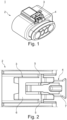
- Fig. 1 illustrates an exemplary connector 1 of the prior art.
- the connector 1 comprises a housing 2 which defines a mating direction and which may encompass a terminal housing.
- the connector 1 comprises a locking arm 3 to lock the connector 1 to a corresponding counter connector.
- the connector 1 comprises a CPA member 4 which is arranged movable along the mating direction of the connector 1. In the configuration illustrated in Fig. 1 , the CPA member is in an open position, in which it does not block a lock release movement of the locking arm 3. In a closed position, in which the CPA member 4 is inserted further into the housing, the CPA member 4 prevents the locking arm 3 from releasing the counter connector.
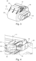
- Fig. 2 schematically illustrates a top view of the prior art connector 1 of Fig. 1 .
- the locking arm 3 is linked to the connector housing 2 via two tortional hinges 5 to allow for a pivotal movement of the locking arm 3.
- the locking arm 3 has locking means 6 adapted for engaging the counter connector and locking the connector 1 to the counter connector, for example by means of a step feature.
- the CPA member 4 has an actuation end 7 protruding at least partially from the housing 2. An operator can move the CPA member 4 along the mating direction, or the operator can press on the top surface of the actuation end 7 to release the primary lock: When the actuation end 7 of the CPA member 4 is pressed downwards, i.e.
- the CPA member 4 urges the locking arm 3 to perform a pivotal movement around a pivot axis which extends through both tortional hinges 5. This pivotal movement is enabled by the tortional hinges 5 which twist during this process. In this way, the locking means 6 of the locking arm 3 is lifted to release the counter connector.
- the tortional hinges 5 are a weak point in the prior art connector design.
- the repeated torsion or twisting of the tortional hinges 5 stresses the material and can lead to mechanical fatigue causing the tortional hinges 5 to break. This also limits the usage of advanced materials, such as e.g. fiberglass, for composing the housing.
- the tortional hinges 5 can prove to be unreliable in high temperature application. Increasing the overall size of the tortional hinges 5 may improve the mechanical durability thereof, but due to the also increased stiffness of enlarged tortional hinges 5, the movement of the locking arm 3 is impaired.
- the present invention aims at providing for an improved connector with a reliable primary locking system, which can advantageously provide for high temperature application.
- the present disclosure provides for a connector, particularly for an electrical connector.
- the connector is preferably designed to be connected to a corresponding counter connector.
- the connector comprises a housing.
- the housing may have an opening into which part of the corresponding counter connector may be inserted upon mating.
- the housing may be configured for insertion into an opening of the corresponding counter connector upon mating.
- the housing may comprise conductive terminals for establishing an electrical connection.
- the housing may encompass an area in which the electrical connection with the corresponding counter connector is established upon mating.
- the housing may comprise an insulating or dielectric material, such as PBT.
- the connector further comprises a locking arm adapted for locking the connector to the corresponding counter connector.
- the locking arm may comprise locking means, for example a lock stop, which can engage the counter connector for locking the connector to the counter connector.
- the locking arm is pivotable between a lock position and a release position. Accordingly, the locking arm can be pivoted around a pivot axis such that a locking engagement of the locking arm with the counter connector can be released.
- the lock position the locking arm is in a position in which it engages the counter connector for locking the connector to the counter connector while in the release position, such a locking engagement is released.
- the locking position is a relaxed position of the locking arm, and in order to reach the release position, the locking arm is deflected by applying a force.
- the locking arm When releasing such force, the locking arm returns to the relaxed position, i.e. the locking position.
- the deflection may occur around a pivot axis which is preferably perpendicular to the mating direction such that the locking arm is deflecting at least partially towards the outer side of the connector.
- the locking arm may comprise the same material as the housing.
- the connector further comprises a linking member linking the locking arm to the housing.
- the linking member may support the locking arm on the housing.
- the linking member may be fixed to the housing via the linking member while still allowing for the pivot movement of the locking arm between the lock position and the release position.
- the linking member comprises a first leg and a second leg and a base portion linking the first leg to the second leg.
- the first leg is linked to the housing, and the second leg is linked to the locking arm.
- the locking arm is eventually affixed to the housing via the second leg, via the base portion, and via the first leg.
- the base portion is affixing the first leg to the second leg in a flexible manner, such that the legs may deflect relative to one another, which allows for the pivot movement of the locking arm as described.
- the locking arm may comprise the same material as the housing.
- the linking member is configured to be flexible, allowing for the two legs to at least partially deflect such that the locking arm is pivoting from the locked position to the release position.
- the legs for example the free ends of the legs which are remote from the base portion, may at least partially deflect away from each other or towards each other.
- the deflection of the legs may lead to the pivot movement of the locking arm with respect to the housing.
- the legs may be deflected between a rest position and a deflected position. Since the locking arm is connected to the second leg of the linking member, the position or state of the linking member may provide for a particular position of the locking arm.
- the locking arm In the rest position, in which the legs may be parallel to each other, the locking arm may be in the lock position. In the deflected position, in which the legs may be at least partially deflected away from each other, the locking arm may be in the release position.
- the locking arm may comprise the same material as the housing.
- the base portion In a direction from the center of the housing towards an outer side of the housing, the base portion is arranged between the first leg and the second leg, and the first leg is further to the outer side than the second leg.
- the second leg is arranged closer to the center of the housing than the first leg, which is located further remote from the center of the housing, and the base portion is in between both legs.
- the first leg may be arranged on the outer periphery of the housing, and the second leg may be arranged beneath the first leg such that it is covered by the first leg when orthogonally looking on the connector surface.
- the direction from the inside of the housing is parallel to a plane defined by the pivotal movement of the locking arm.
- a flexible, secure and reliable support of the locking arm is provided, due to the advantageous design of the flexible linking member. Since the lock mechanism is less prone to material fatigue and breakage, the connector is suitable for high temperature applications. In addition, the proposed connector requires less finger actuation force in order to release the locking of the locking arm. Since tortional hinges are not required any longer to enable the pivot movement of the locking arm, fiberglass material such as fiberglass filled PBT material can be used. The connector can further be manufactured in a simple manner.
- the linking member has an essentially U-shaped cross-section.
- the first leg and the second leg may each define respective legs of the U-shaped cross-section, and the base portion may define connecting part between the two legs of the U-shaped cross-section.
- an opening of the linking member defined by the legs is facing the mating direction or the unmating direction of the connector. That is, one or both of the legs may essentially point towards the mating/unmating direction of the connector. This provides sufficient clearance for flexing the linking member such that the legs can be sufficiently deflected with reduced amount of material stress.
- the legs have an elongated shape, and the base portion has a curved shape. This allows for a secure fixation of the legs to the housing and locking arm, respectively.
- the curved shape of the base portion allows for a resilient form of the linking member, with reduced risk of mechanical fatigue due to repeated operation of the locking arm.
- the legs when the linking member is in the relaxed state and the locking arm is in the locked position, the legs are essentially parallel to each other. From such a configuration, the legs can be deflected without unduly straining the base portion. When the legs are deflected, they may no longer be parallel to each other, and the base portion may be elastically deformed.
- the first leg is aligned along the mating direction of the connector.
- a main extension of the first leg may be parallel to the mating or unmating direction of the connector. This allows for deflecting the legs without unduly straining the base portion.
- the main extension direction of the base portion lies essentially parallel to a pivoting plane defined by the pivot movement of the locking arm, and the pivoting plane is preferably parallel to the mating direction of the connector.
- the base portion may thus extend from the first leg to the second leg along a direction which is parallel to the pivoting plane of the locking arm.
- the pivoting plane may be defined by the pivoting movement, i.e. it may be parallel to the movement direction of the locking arm.
- the base portion of the linking member is adapted to elastically deform when the two legs at least partially deflect. Since the base portion connects the first leg to the second leg, deflection of the legs may cause the deformation of the base portion.
- the elastic deformation preferably comprises a compression and/or stretching of the base portion, preferably without any torsion of the base portion. In this way, the durability of the connector and its locking mechanism is increased.
- the connector further comprises a CPA member configured movable along the mating direction and relative to the housing between an open position and a closed position.
- the CPA member may ensure the correct mating connector and/or the correct locking position of the locking arm.
- the CPA member may be designed such that it can only be operated to move from the open position to the closed position when the locking arm is in the lock position.
- a blocking abutment of the CPA member with the locking arm may prevent the locking arm from reaching the release position. Only when the CPA member has been retracted to the open position, the locking arm may be enabled to reach the release position.
- Providing a CPA member may increase the reliability of the connection of the connector with the counter connector.
- the CPA member is in contact with the locking arm such that, when the CPA member is in the open position, a transversal actuation of the CPA member urges the locking arm to pivot from the locked position to the release position.
- An operator may press on a top surface or edge of the CPA member, preferably at one end thereof, towards the center of the housing.
- the CPA member may come into contact with the locking arm, directly or indirectly, and urge the locking arm to pivot from the lock position to the release position. It is thus possible to operate the locking mechanism in an easy and intuitive manner while also providing for a CPA member.
- the connector comprises two linking members arranged on opposite sides of the locking arm.
- the connector may comprise two linking members as described herein, to link the locking arm to the housing.
- the pivot axis of the pivotal movement of the locking arm may extend through both linking members.
- the housing, the linking member, and the locking arm are integrally formed.
- the housing, the linking member, and the locking arm may thus form a single, integral part of the connector.
- the housing, the linking member, and the locking arm may be produced as a single component, for example by means of injection molding. This reduces the manufacturing efforts.
- the first leg is at least partially formed integrally with an outer surface of the housing.
- the first leg may thus be defined at least partially by the outer surface of the housing, i.e. the first leg may be a part of the outer surface of the housing. This allows for reducing the overall dimensions of the connector.
- a gap between the legs of the linking member in the relaxed state is larger than a thickness of the base portion and/or of the second leg.
- the gap may be measured between free end points of the legs, preferably perpendicular to the main extension direction of the first or second leg, and the thickness of the base portion and/or of the second leg may be measured in the pivoting plane.
- a width of the base portion of the linking member measured along the pivot axis of the locking arm is larger than a thickness of the base portion and/or of the second leg.
- the width may be measured in a direction parallel to the pivot axis of the locking arm, or parallel to a deflection axis of the linking member.
- At least one of the housing, the linking member, and the locking arm comprises fiberglass, more preferred at least 10% fiberglass, more preferred at least 20% fiberglass, more preferred at least 30% fiberglass, more preferred at least 40% fiberglass, most preferred at least 50% fiberglass.
- the housing, linking member, and the locking arm may be made of fiberglass reinforced plastic. This provides for high durability, low weight, and high robustness, in addition to weather and temperature resistance.
- Fig. 3 illustrates a connector 10 according to an embodiment of the invention.
- the connector 10 is designed to be connected to a corresponding counter connector.
- the connector 10 is designed as a female connector and comprises a connector housing 20 which has wiring openings 23 for receiving electrical wiring or electrical terminals.
- the connector housing 20 further comprises a mating opening 22 opposite of the wiring openings 23 which is adapted for receiving the corresponding counter connector during mating.
- the main axis of the mating opening 22 may define the mating and unmating directions of the connector, which is indicated by the dotted line 70.
- the connector can be locked to the counter connector by means of a locking mechanism with a locking arm and linking member as described herein.
- the connector 10 further comprises a CPA member 30 which can be moved along the mating direction 70 of the connector 10 between an open position (illustrated in Fig. 3 ) and a closed position, in which the CPA member 30 is inserted further into the connector housing 20.
- the CPA member 30 is provided in a corresponding opening provided in the housing 20, partially beneath a top surface 21 of the connector housing 20.
- Fig. 4 illustrates a detailed view of the connector of Fig. 3 .
- the CPA member 30 has an actuation surface 31 on its free end, i.e. on the end protruding from the housing 20 along the mating/unmating direction 70.
- the CPA member 30 further has an actuation edge 32 bordering the actuating surface 31.
- the actuation edge 32 is facing away from a center of the connector 10, such that it can easily be actuated by an operator for releasing the locking mechanism.
- the connector 10 comprises a linking member 50.
- the linking member 50 links or connects a locking arm of the connector to the housing 20, as will be described further below.
- the linking member 50 has a U-shaped cross-section with a first leg 51, a second leg 52, and a base portion 53 linking the first leg 51 with the second leg 52.
- the U-shaped cross-section defines an opening 54 facing away from the mating end of the connector 10.
- the first leg 51 is integrally formed with the outside surface 21 of the connector housing 20.
- the first leg 51 is arranged parallel to the second leg 52 when the legs are not deflected as illustrated in Fig. 4 .
- the base portion 53 has a curved shape, providing for a smooth and step-free transition from the first leg 51 to the second leg 52, at least on the inner side of the U-shaped linking member 50, preferably also on the outer side as seen in Fig. 4 .
- the second leg 52 is linked to a locking arm of the locking mechanism, as will be described further below.
- the base portion 53 of the linking member 50 is arranged between the first leg 51 and the second leg 52, and the first leg 51 is further to the outer side than the second leg 52.
- the direction 71 indicated by the dotted line may be perpendicular to the mating direction 70 and perpendicular to a transversal direction of the connector 1, wherein the transversal direction may be parallel to a pivot axis 72 of the locking arm as described further below.
- the U-shaped linking member 50 is designed flexible allowing for the two legs 51, 52 to at least partially deflect away from each other.
- the CPA member 30 rest on the locking arm of the locking mechanism which is linked to the second leg 52. Accordingly, when pressing onto the actuation edge 32 of the CPA member 30, thereby urging the free end of the CPA member to move towards the center of the housing 20, the second leg 52 of the U-shaped linking member 50 is urged to deflect away from the first leg 51, while the base portion 53 is elastically deforming by being stretched on its inner side.
- Fig. 5 illustrates a detailed view of a connector of another embodiment of the invention.
- Fig. 5 particularly illustrates a view of the top part of the connector of Fig. 3 along the mating direction 70 but without the CPA member.
- the CPA member 30 can generally be inserted.
- the first legs 51 of the U-shaped linking members 50 are integrally formed with the outer surface 21 of the housing 20.
- the curved base sections 53 extend from the first legs 51 to the second legs 52, which in turn are linked to the locking arm 40 of the connector 10.
- the locking arm 40 comprises a locking stop 41 which may come into blocking contact with a corresponding feature of the corresponding counter connector in order to lock the connectors.
- the locking arm 40 In the configuration illustrated in Fig. 5 , the locking arm 40 is in the lock position. In a release position, in which the locking arm is pivoted such that the locking stop 41 is lifted upwards, the counter connector can be released.
- the locking arm 40 comprises abutting surfaces 42 onto which the CPA member 30 may be positioned. The abutting surfaces 42 are linked to the second legs 52 of the U-shaped linking members 50.
- the locking arm can pivot around a pivot axis 72 which is parallel to a transversal direction of the housing, which is perpendicular to both the mating direction 70 and the direction 71 from a center of the housing towards an outer side of the housing.
- the pivot axis 72 may eventually be defined by the configuration and dimensions of the base portions 53 of the U-shaped linking members 50.
- the width w of the base portion 53 is larger than the thickness t 2 of the second leg 52.
- the width may be measured along the pivot axis 72 of the locking arm 40.
- the thickness of the legs may be measured perpendicular to the mating direction 70 and perpendicular to the pivot axis 72 of the locking arm 40.
- Fig. 6 illustrates a cross-sectional view of the connector of Fig. 5 .
- the cross-sectional view is perpendicular to the mating direction 70, and the cross-sectional plane corresponds to the pivoting plane defined by the pivotal movement of the locking arm 40.
- the first leg 51 is integrally formed with the top surface 21 of the housing.
- the base portion 53 is extending away from the first leg 51 in a direction towards the center of the housing.
- the inner and outer sides of the base portion 53 are curved and the base portion 53 smoothly transitions into the second leg 52, which is parallel to the top surface 21 of the housing and the first leg 51.
- the locking arm 40 is linked to the second leg 52 such that a deflection of the second leg 52 relative to the first leg 51 causes a reorientation of the locking arm 40.
- the gap g between the legs 51, 52 of the U-shaped linking member 50 in the relaxed state as illustrated in Fig. 6 is larger than the thickness t b of the base portion, larger than the thickness t 1 of the first leg, and larger than the thickness t 2 of the second leg (cf. Fig. 5 ).
- the connector may comprise additional elements such as e.g. a sealing member 60, or electrical terminals inserted into the wiring openings 23.
- Fig. 7 illustrates schematically the operation of the locking mechanism.
- the legs 51 and 52 are parallel to each other, and the base portion 53 is in a stress-free state.
- the locking arm 40 is in the lock position in which it can lock the connector to the counter connector.
- the CPA member 30 is inserted into the housing along the mating direction 70.
- the CPA member 30 rests at least partially on the locking arm 40.
- the locking arm 40 is still in the lock position, and the CPA member 30 is in the open position.
- a force has been applied onto the actuation edge 32 of the CPA member 30 urging the CPA member 30 downwards towards the center of the connector.
- the base portion 53 is elastically deformed and the second arm 52 is moved downwards as well as the rear end of the locking arm 40, which is linked to the second arm 52. Due to this movement, the locking arm 40 is pivoted around the pivot axis 72, such that the part of the locking arm 40 with the locking means is lifted upwards. In this manner, the locking arm 40 reaches the release position in which the counter connector is released.
Landscapes
- Details Of Connecting Devices For Male And Female Coupling (AREA)
Abstract
The present disclosure relates to a connector, particularly to an electrical connector. The connector comprises a housing and a locking arm adapted for locking the connector to a corresponding counter connector. The locking arm is pivotable between a lock position and a release position. The connector further comprises a linking member linking the locking arm to the housing.
Description
- The present disclosure relates to a connector, in particular to an electrical connector, which is adapted for being connected to a corresponding counter connector. The connector comprises a housing and a locking arm. The locking arm is adapted for locking the connector to the corresponding counter connector. Further, the locking arm is pivotable between a lock position and a release position.
- Connectors and electrical connectors are widely known in the field. Electrical connectors are designed to connect electrical cables, wires or cable harnesses to each other, or to connect these to electrical or electronic devices. Electrical connectors usually comprise an insulating housing in which conductive terminals may be arranged.
- For certain applications, it is important to ensure that the connectors are properly and securely mated. A primary lock system may be provided for locking the two mated connectors. The primary lock system may comprise a stop arranged on one of the connectors, and a locking arm with a stop arranged on the other connector. The stop of the locking arm may engage the other stop when the connectors are mated in order to lock the connectors to each other.
- In addition, it is known to use a so-called connection position assurance (CPA) member which ensures the correct mating position. The CPA member may be designed such that it can only be operated when the connectors are correctly mated and locked by means of the primary lock system.
-
Fig. 1 illustrates anexemplary connector 1 of the prior art. Theconnector 1 comprises ahousing 2 which defines a mating direction and which may encompass a terminal housing. Theconnector 1 comprises alocking arm 3 to lock theconnector 1 to a corresponding counter connector. Further, theconnector 1 comprises aCPA member 4 which is arranged movable along the mating direction of theconnector 1. In the configuration illustrated inFig. 1 , the CPA member is in an open position, in which it does not block a lock release movement of thelocking arm 3. In a closed position, in which theCPA member 4 is inserted further into the housing, theCPA member 4 prevents thelocking arm 3 from releasing the counter connector. -
Fig. 2 schematically illustrates a top view of theprior art connector 1 ofFig. 1 . Thelocking arm 3 is linked to theconnector housing 2 via twotortional hinges 5 to allow for a pivotal movement of thelocking arm 3. Thelocking arm 3 has locking means 6 adapted for engaging the counter connector and locking theconnector 1 to the counter connector, for example by means of a step feature. Further, theCPA member 4 has anactuation end 7 protruding at least partially from thehousing 2. An operator can move theCPA member 4 along the mating direction, or the operator can press on the top surface of theactuation end 7 to release the primary lock: When theactuation end 7 of theCPA member 4 is pressed downwards, i.e. towards the center of thehousing 2, theCPA member 4 urges thelocking arm 3 to perform a pivotal movement around a pivot axis which extends through bothtortional hinges 5. This pivotal movement is enabled by thetortional hinges 5 which twist during this process. In this way, the locking means 6 of thelocking arm 3 is lifted to release the counter connector. - The
tortional hinges 5 are a weak point in the prior art connector design. The repeated torsion or twisting of thetortional hinges 5 stresses the material and can lead to mechanical fatigue causing thetortional hinges 5 to break. This also limits the usage of advanced materials, such as e.g. fiberglass, for composing the housing. In addition, thetortional hinges 5 can prove to be unreliable in high temperature application. Increasing the overall size of thetortional hinges 5 may improve the mechanical durability thereof, but due to the also increased stiffness of enlargedtortional hinges 5, the movement of thelocking arm 3 is impaired. - It is thus an object of the present invention to provide for an improved connector design which allows for overcoming the above deficiencies at least partially. In particular, the present invention aims at providing for an improved connector with a reliable primary locking system, which can advantageously provide for high temperature application.
- A solution is provided according to the subject matter of
independent claim 1. Particularly preferred embodiments are specified in the dependent claims. - The present disclosure provides for a connector, particularly for an electrical connector. The connector is preferably designed to be connected to a corresponding counter connector.
- The connector comprises a housing. The housing may have an opening into which part of the corresponding counter connector may be inserted upon mating. Alternatively, the housing may be configured for insertion into an opening of the corresponding counter connector upon mating. As will be appreciated by the skilled person, the housing may comprise conductive terminals for establishing an electrical connection. The housing may encompass an area in which the electrical connection with the corresponding counter connector is established upon mating. The housing may comprise an insulating or dielectric material, such as PBT.
- The connector further comprises a locking arm adapted for locking the connector to the corresponding counter connector. The locking arm may comprise locking means, for example a lock stop, which can engage the counter connector for locking the connector to the counter connector. The locking arm is pivotable between a lock position and a release position. Accordingly, the locking arm can be pivoted around a pivot axis such that a locking engagement of the locking arm with the counter connector can be released. In the lock position, the locking arm is in a position in which it engages the counter connector for locking the connector to the counter connector while in the release position, such a locking engagement is released. Preferably, the locking position is a relaxed position of the locking arm, and in order to reach the release position, the locking arm is deflected by applying a force. When releasing such force, the locking arm returns to the relaxed position, i.e. the locking position. The deflection may occur around a pivot axis which is preferably perpendicular to the mating direction such that the locking arm is deflecting at least partially towards the outer side of the connector. The locking arm may comprise the same material as the housing.
- The connector further comprises a linking member linking the locking arm to the housing. The linking member may support the locking arm on the housing. The linking member may be fixed to the housing via the linking member while still allowing for the pivot movement of the locking arm between the lock position and the release position. The linking member comprises a first leg and a second leg and a base portion linking the first leg to the second leg. The first leg is linked to the housing, and the second leg is linked to the locking arm. Thus, the locking arm is eventually affixed to the housing via the second leg, via the base portion, and via the first leg. The base portion is affixing the first leg to the second leg in a flexible manner, such that the legs may deflect relative to one another, which allows for the pivot movement of the locking arm as described. The locking arm may comprise the same material as the housing.
- The linking member is configured to be flexible, allowing for the two legs to at least partially deflect such that the locking arm is pivoting from the locked position to the release position. The legs, for example the free ends of the legs which are remote from the base portion, may at least partially deflect away from each other or towards each other. As the first leg is linked to the housing and the second leg is linked to the locking arm, the deflection of the legs may lead to the pivot movement of the locking arm with respect to the housing. The legs may be deflected between a rest position and a deflected position. Since the locking arm is connected to the second leg of the linking member, the position or state of the linking member may provide for a particular position of the locking arm. In the rest position, in which the legs may be parallel to each other, the locking arm may be in the lock position. In the deflected position, in which the legs may be at least partially deflected away from each other, the locking arm may be in the release position. The locking arm may comprise the same material as the housing.
- In a direction from the center of the housing towards an outer side of the housing, the base portion is arranged between the first leg and the second leg, and the first leg is further to the outer side than the second leg. In other words, the second leg is arranged closer to the center of the housing than the first leg, which is located further remote from the center of the housing, and the base portion is in between both legs. For example, the first leg may be arranged on the outer periphery of the housing, and the second leg may be arranged beneath the first leg such that it is covered by the first leg when orthogonally looking on the connector surface. Preferably, the direction from the inside of the housing is parallel to a plane defined by the pivotal movement of the locking arm.
- According to the present invention, a flexible, secure and reliable support of the locking arm is provided, due to the advantageous design of the flexible linking member. Since the lock mechanism is less prone to material fatigue and breakage, the connector is suitable for high temperature applications. In addition, the proposed connector requires less finger actuation force in order to release the locking of the locking arm. Since tortional hinges are not required any longer to enable the pivot movement of the locking arm, fiberglass material such as fiberglass filled PBT material can be used. The connector can further be manufactured in a simple manner.
- In a preferred embodiment, the linking member has an essentially U-shaped cross-section. This allows for a particularly reliable and flexible structure of the linking member. The first leg and the second leg may each define respective legs of the U-shaped cross-section, and the base portion may define connecting part between the two legs of the U-shaped cross-section. As will be understood by the skilled person, there may be a smooth transition between the legs and the base portion, particularly on the inner side of the U-shaped cross-section. This provides for a reliable and durable primary locking and release mechanism.
- Further preferred, an opening of the linking member defined by the legs is facing the mating direction or the unmating direction of the connector. That is, one or both of the legs may essentially point towards the mating/unmating direction of the connector. This provides sufficient clearance for flexing the linking member such that the legs can be sufficiently deflected with reduced amount of material stress.
- Preferably, the legs have an elongated shape, and the base portion has a curved shape. This allows for a secure fixation of the legs to the housing and locking arm, respectively.
- The curved shape of the base portion allows for a resilient form of the linking member, with reduced risk of mechanical fatigue due to repeated operation of the locking arm.
- Preferably, when the linking member is in the relaxed state and the locking arm is in the locked position, the legs are essentially parallel to each other. From such a configuration, the legs can be deflected without unduly straining the base portion. When the legs are deflected, they may no longer be parallel to each other, and the base portion may be elastically deformed.
- Preferably, the first leg is aligned along the mating direction of the connector. In other words, a main extension of the first leg may be parallel to the mating or unmating direction of the connector. This allows for deflecting the legs without unduly straining the base portion.
- Preferably, the main extension direction of the base portion lies essentially parallel to a pivoting plane defined by the pivot movement of the locking arm, and the pivoting plane is preferably parallel to the mating direction of the connector. The base portion may thus extend from the first leg to the second leg along a direction which is parallel to the pivoting plane of the locking arm. The pivoting plane may be defined by the pivoting movement, i.e. it may be parallel to the movement direction of the locking arm. With the base portion extending parallel to the pivoting plane of the locking arm, the base portion may only be compressed and stretched when the legs are deflected, preferably without any torsional movement. In this manner, the stability and durability of the connector and its locking mechanism is increased.
- Preferably, the base portion of the linking member is adapted to elastically deform when the two legs at least partially deflect. Since the base portion connects the first leg to the second leg, deflection of the legs may cause the deformation of the base portion. The elastic deformation preferably comprises a compression and/or stretching of the base portion, preferably without any torsion of the base portion. In this way, the durability of the connector and its locking mechanism is increased.
- In a preferred embodiment, the connector further comprises a CPA member configured movable along the mating direction and relative to the housing between an open position and a closed position. As known by the skilled person, the CPA member may ensure the correct mating connector and/or the correct locking position of the locking arm. The CPA member may be designed such that it can only be operated to move from the open position to the closed position when the locking arm is in the lock position. When the locking arm is in the lock position and the CPA member is in the closed position, a blocking abutment of the CPA member with the locking arm may prevent the locking arm from reaching the release position. Only when the CPA member has been retracted to the open position, the locking arm may be enabled to reach the release position. Providing a CPA member may increase the reliability of the connection of the connector with the counter connector.
- Further preferred, the CPA member is in contact with the locking arm such that, when the CPA member is in the open position, a transversal actuation of the CPA member urges the locking arm to pivot from the locked position to the release position. An operator may press on a top surface or edge of the CPA member, preferably at one end thereof, towards the center of the housing. The CPA member may come into contact with the locking arm, directly or indirectly, and urge the locking arm to pivot from the lock position to the release position. It is thus possible to operate the locking mechanism in an easy and intuitive manner while also providing for a CPA member.
- Preferably, the connector comprises two linking members arranged on opposite sides of the locking arm. Accordingly, the connector may comprise two linking members as described herein, to link the locking arm to the housing. The pivot axis of the pivotal movement of the locking arm may extend through both linking members. Eventually, a more stable and durable configuration of the connector and the locking mechanism is provided for.
- Preferably, the housing, the linking member, and the locking arm are integrally formed. The housing, the linking member, and the locking arm may thus form a single, integral part of the connector. The housing, the linking member, and the locking arm may be produced as a single component, for example by means of injection molding. This reduces the manufacturing efforts.
- Preferably, the first leg is at least partially formed integrally with an outer surface of the housing. The first leg may thus be defined at least partially by the outer surface of the housing, i.e. the first leg may be a part of the outer surface of the housing. This allows for reducing the overall dimensions of the connector.
- Preferably, a gap between the legs of the linking member in the relaxed state is larger than a thickness of the base portion and/or of the second leg. The gap may be measured between free end points of the legs, preferably perpendicular to the main extension direction of the first or second leg, and the thickness of the base portion and/or of the second leg may be measured in the pivoting plane. By providing a rather large gap between the legs, sufficient flexibility of the linking member can be provided for, and the force required for operating the locking mechanism of the locking arm is reduced.
- Preferably, a width of the base portion of the linking member measured along the pivot axis of the locking arm is larger than a thickness of the base portion and/or of the second leg. The width may be measured in a direction parallel to the pivot axis of the locking arm, or parallel to a deflection axis of the linking member. By providing a rather wide base portion, the durability of the linking member is increased.
- Preferably, at least one of the housing, the linking member, and the locking arm comprises fiberglass, more preferred at least 10% fiberglass, more preferred at least 20% fiberglass, more preferred at least 30% fiberglass, more preferred at least 40% fiberglass, most preferred at least 50% fiberglass. The housing, linking member, and the locking arm may be made of fiberglass reinforced plastic. This provides for high durability, low weight, and high robustness, in addition to weather and temperature resistance.
- In the following, the present invention is described with reference to the accompanying figures. In the figures, similar elements are provided with equal reference signs.
- Fig. 1
- illustrates a connector design according to the prior art;
- Fig. 2
- illustrates the prior art connector of
Fig. 1 in another view; - Fig. 3
- illustrates a connector according to an embodiment of the invention;
- Fig. 4
- illustrates a detailed view of the connector of
Fig. 3 ; - Fig. 5
- illustrates a detailed view of a connector of another embodiment of the invention;
- Fig. 6
- illustrates a cross-sectional view of the connector of
Fig. 5 ; - Fig. 7
- illustrates schematically the operation of the locking mechanism according to the invention.
-
Fig. 3 illustrates aconnector 10 according to an embodiment of the invention. As described herein, theconnector 10 is designed to be connected to a corresponding counter connector. Theconnector 10 is designed as a female connector and comprises aconnector housing 20 which haswiring openings 23 for receiving electrical wiring or electrical terminals. Theconnector housing 20 further comprises amating opening 22 opposite of thewiring openings 23 which is adapted for receiving the corresponding counter connector during mating. The main axis of themating opening 22 may define the mating and unmating directions of the connector, which is indicated by the dottedline 70. The connector can be locked to the counter connector by means of a locking mechanism with a locking arm and linking member as described herein. - The
connector 10 further comprises aCPA member 30 which can be moved along themating direction 70 of theconnector 10 between an open position (illustrated inFig. 3 ) and a closed position, in which theCPA member 30 is inserted further into theconnector housing 20. TheCPA member 30 is provided in a corresponding opening provided in thehousing 20, partially beneath atop surface 21 of theconnector housing 20. -
Fig. 4 illustrates a detailed view of the connector ofFig. 3 . TheCPA member 30 has anactuation surface 31 on its free end, i.e. on the end protruding from thehousing 20 along the mating/unmating direction 70. TheCPA member 30 further has anactuation edge 32 bordering the actuating surface 31.Theactuation edge 32 is facing away from a center of theconnector 10, such that it can easily be actuated by an operator for releasing the locking mechanism. - As can further be seen from
Fig. 4 , theconnector 10 comprises a linkingmember 50. The linkingmember 50 links or connects a locking arm of the connector to thehousing 20, as will be described further below. The linkingmember 50 has a U-shaped cross-section with afirst leg 51, asecond leg 52, and abase portion 53 linking thefirst leg 51 with thesecond leg 52. The U-shaped cross-section defines anopening 54 facing away from the mating end of theconnector 10. Thefirst leg 51 is integrally formed with theoutside surface 21 of theconnector housing 20. Thefirst leg 51 is arranged parallel to thesecond leg 52 when the legs are not deflected as illustrated inFig. 4 . Thebase portion 53 has a curved shape, providing for a smooth and step-free transition from thefirst leg 51 to thesecond leg 52, at least on the inner side of theU-shaped linking member 50, preferably also on the outer side as seen inFig. 4 . Thesecond leg 52 is linked to a locking arm of the locking mechanism, as will be described further below. - In a
direction 71 from a center of the housing towards an outer side of the housing, which is indicated inFig. 4 by a dotted line, thebase portion 53 of the linkingmember 50 is arranged between thefirst leg 51 and thesecond leg 52, and thefirst leg 51 is further to the outer side than thesecond leg 52. Thedirection 71 indicated by the dotted line may be perpendicular to themating direction 70 and perpendicular to a transversal direction of theconnector 1, wherein the transversal direction may be parallel to apivot axis 72 of the locking arm as described further below. - The
U-shaped linking member 50 is designed flexible allowing for the twolegs CPA member 30 rest on the locking arm of the locking mechanism which is linked to thesecond leg 52. Accordingly, when pressing onto theactuation edge 32 of theCPA member 30, thereby urging the free end of the CPA member to move towards the center of thehousing 20, thesecond leg 52 of theU-shaped linking member 50 is urged to deflect away from thefirst leg 51, while thebase portion 53 is elastically deforming by being stretched on its inner side. -
Fig. 5 illustrates a detailed view of a connector of another embodiment of the invention.Fig. 5 particularly illustrates a view of the top part of the connector ofFig. 3 along themating direction 70 but without the CPA member. There are provided twoU-shaped linking members 50 each having afirst leg 51, asecond leg 52, and abase portion 53 as described with regard toFig. 3 and Fig. 4 . In between the linkingmembers 50, theCPA member 30 can generally be inserted. Thefirst legs 51 of theU-shaped linking members 50 are integrally formed with theouter surface 21 of thehousing 20. Thecurved base sections 53 extend from thefirst legs 51 to thesecond legs 52, which in turn are linked to the lockingarm 40 of theconnector 10. - The locking
arm 40 comprises a lockingstop 41 which may come into blocking contact with a corresponding feature of the corresponding counter connector in order to lock the connectors. In the configuration illustrated inFig. 5 , the lockingarm 40 is in the lock position. In a release position, in which the locking arm is pivoted such that the lockingstop 41 is lifted upwards, the counter connector can be released. The lockingarm 40 comprises abuttingsurfaces 42 onto which theCPA member 30 may be positioned. The abutting surfaces 42 are linked to thesecond legs 52 of theU-shaped linking members 50. - When pressing onto the abutting
surfaces 42, or when pressing onto theCPA member 30 positioned on the abuttingsurfaces 42, the abuttingsurfaces 42 are pushed down thereby urging thesecond legs 52 downwards towards the center of thehousing 20, which movement is enabled by an elastic deformation of thebase portions 53. This results in a pivot movement of the lockingarm 40 such that the lockingstop 41 of the lockingarm 40 is moved upwards, i.e. away from the center of thehousing 20, such that the lockingarm 40 reaches the release position. - The locking arm can pivot around a
pivot axis 72 which is parallel to a transversal direction of the housing, which is perpendicular to both themating direction 70 and thedirection 71 from a center of the housing towards an outer side of the housing. Thepivot axis 72 may eventually be defined by the configuration and dimensions of thebase portions 53 of theU-shaped linking members 50. - The width w of the
base portion 53 is larger than the thickness t2 of thesecond leg 52. The width may be measured along thepivot axis 72 of the lockingarm 40. The thickness of the legs may be measured perpendicular to themating direction 70 and perpendicular to thepivot axis 72 of the lockingarm 40. -
Fig. 6 illustrates a cross-sectional view of the connector ofFig. 5 . The cross-sectional view is perpendicular to themating direction 70, and the cross-sectional plane corresponds to the pivoting plane defined by the pivotal movement of the lockingarm 40. As can also be seen in thisFig. 6 , thefirst leg 51 is integrally formed with thetop surface 21 of the housing. Thebase portion 53 is extending away from thefirst leg 51 in a direction towards the center of the housing. The inner and outer sides of thebase portion 53 are curved and thebase portion 53 smoothly transitions into thesecond leg 52, which is parallel to thetop surface 21 of the housing and thefirst leg 51. The lockingarm 40 is linked to thesecond leg 52 such that a deflection of thesecond leg 52 relative to thefirst leg 51 causes a reorientation of the lockingarm 40. The gap g between thelegs U-shaped linking member 50 in the relaxed state as illustrated inFig. 6 is larger than the thickness tb of the base portion, larger than the thickness t1 of the first leg, and larger than the thickness t2 of the second leg (cf.Fig. 5 ). - As can further be seen from
Fig. 6 , the connector may comprise additional elements such as e.g. a sealingmember 60, or electrical terminals inserted into thewiring openings 23. -
Fig. 7 illustrates schematically the operation of the locking mechanism. In the first configuration (a), thelegs base portion 53 is in a stress-free state. The lockingarm 40 is in the lock position in which it can lock the connector to the counter connector. In the second configuration (b), theCPA member 30 is inserted into the housing along themating direction 70. TheCPA member 30 rests at least partially on the lockingarm 40. The lockingarm 40 is still in the lock position, and theCPA member 30 is in the open position. In the third configuration (c), a force has been applied onto theactuation edge 32 of theCPA member 30 urging theCPA member 30 downwards towards the center of the connector. As a result, thebase portion 53 is elastically deformed and thesecond arm 52 is moved downwards as well as the rear end of the lockingarm 40, which is linked to thesecond arm 52. Due to this movement, the lockingarm 40 is pivoted around thepivot axis 72, such that the part of the lockingarm 40 with the locking means is lifted upwards. In this manner, the lockingarm 40 reaches the release position in which the counter connector is released.
Claims (15)
- A connector (10), particularly an electrical connector, comprising:a housing (20);a locking arm (40) adapted for locking the connector (10) to a corresponding counter connector;wherein the locking arm (40) is pivotable between a lock position and a release position;characterized in that the connector (10) further comprises:a linking member (50) linking the locking arm (40) to the housing (20);wherein the linking member (50) comprises a first leg (51) and a second leg (52) and a base portion (53) linking the first leg (51) to the second leg (52);wherein the first leg (51) is linked to the housing (20);wherein the second leg (52) is linked to the locking arm (40);wherein the linking member (50) is configured to be flexible allowing for the two legs (51, 52) to at least partially deflect such that the locking arm (40) is pivoting from the locked position to the release position; andwherein, in a direction (71) from a center of the housing (20) towards an outer side of the housing (20), the base portion (53) is arranged between the first leg (51) and the second leg (52), and the first leg (51) is further to the outer side than the second leg (52).
- The connector (10) of claim 1, wherein the linking member (50) has an essentially U-shaped cross-section.
- The connector (10) of claim 1 or 2, wherein an opening of the linking member (50) defined by the legs is facing the mating direction (70) or the unmating direction (70) of the connector.
- The connector (10) of any one of claims 1-3, wherein the legs have an elongated shape, and wherein the base portion (53) has a curved shape.
- The connector (10) of any one of claims 1-4, wherein, when the linking member (50) is in the relaxed state and the locking arm (40) is in the locked position, the legs (51, 52) are essentially parallel to each other.
- The connector (10) of any one of claims 1-5, wherein the first leg (51) is aligned along the mating direction (70) of the connector (10).
- The connector (10) of any one of claims 1-6, wherein the main extension direction of the base portion (53) is essential parallel to a pivoting plane defined by the pivot movement of the locking arm (40), and wherein the pivoting plane is parallel to the mating direction (70) of the connector (10).
- The connector (10) of any one of claims 1-7, wherein the base portion (53) of the linking member (50) is adapted to elastically deform when the two legs (51, 52) at least partially deflect.
- The connector (10) of any one of claims 1-8, further comprising a CPA member (30) configured movable along the mating direction and relative to the housing (20) between an open position and a closed position,
in particular wherein the CPA member (30) is in contact with the locking arm (40) such that, when the CPA member (30) is in the open position, a transversal actuation of the CPA member (30) urges the locking arm (40) to pivot from the locked position to the release position. - The connector (10) of any one of claims 1-9, wherein the connector comprises two linking members (50) arranged on opposite sides of the locking arm (40).
- The connector (10) of any one of claims 1-10, wherein the housing (20), the linking member (50) and the locking arm (40) are integrally formed.
- The connector (10) of any one of claims 1-11, wherein the first leg (51) is at least partially formed integrally with an outer surface (21) of the housing (20).
- The connector (10) of any one of claims 1-12, wherein a gap between the legs (51, 52) of the linking member (50) in the relaxed state is larger than a thickness of the base portion (53) and/or of the second leg (52).
- The connector (10) of any one of claims 1-13, wherein a width of the base portion (53) of the linking member (50) measured along the pivot axis of the locking arm (40) is larger than a thickness of the base portion (53) and/or of the second leg (52).
- The connector (10) of any one of claims 1-14, wherein at least one of the housing (20), linking member (50) and locking arm (40) comprises fiberglass, preferably at least 10% fiberglass, more preferred at least 20% fiberglass, most preferred at least 30% fiberglass.
Priority Applications (2)
| Application Number | Priority Date | Filing Date | Title |
|---|---|---|---|
| EP23212850.4A EP4564615A1 (en) | 2023-11-29 | 2023-11-29 | Connector with durable locking mechanism |
| US18/961,876 US20250174940A1 (en) | 2023-11-29 | 2024-11-27 | Connector with Durable Locking Mechanism |
Applications Claiming Priority (1)
| Application Number | Priority Date | Filing Date | Title |
|---|---|---|---|
| EP23212850.4A EP4564615A1 (en) | 2023-11-29 | 2023-11-29 | Connector with durable locking mechanism |
Publications (1)
| Publication Number | Publication Date |
|---|---|
| EP4564615A1 true EP4564615A1 (en) | 2025-06-04 |
Family
ID=88978570
Family Applications (1)
| Application Number | Title | Priority Date | Filing Date |
|---|---|---|---|
| EP23212850.4A Pending EP4564615A1 (en) | 2023-11-29 | 2023-11-29 | Connector with durable locking mechanism |
Country Status (2)
| Country | Link |
|---|---|
| US (1) | US20250174940A1 (en) |
| EP (1) | EP4564615A1 (en) |
Citations (4)
| Publication number | Priority date | Publication date | Assignee | Title |
|---|---|---|---|---|
| US20010049219A1 (en) * | 2000-05-31 | 2001-12-06 | Yazaki Corporation | Half-fitting prevention connector |
| CN102570133A (en) * | 2010-12-15 | 2012-07-11 | 住友电装株式会社 | Connector |
| WO2015076378A1 (en) * | 2013-11-25 | 2015-05-28 | 矢崎総業株式会社 | Connector |
| JP6808062B2 (en) * | 2017-03-20 | 2021-01-06 | ロベルト・ボッシュ・ゲゼルシャフト・ミト・ベシュレンクテル・ハフツングRobert Bosch Gmbh | A housing that includes a connector for joining the two housing parts and two housing parts and at least one connector. |
-
2023
- 2023-11-29 EP EP23212850.4A patent/EP4564615A1/en active Pending
-
2024
- 2024-11-27 US US18/961,876 patent/US20250174940A1/en active Pending
Patent Citations (4)
| Publication number | Priority date | Publication date | Assignee | Title |
|---|---|---|---|---|
| US20010049219A1 (en) * | 2000-05-31 | 2001-12-06 | Yazaki Corporation | Half-fitting prevention connector |
| CN102570133A (en) * | 2010-12-15 | 2012-07-11 | 住友电装株式会社 | Connector |
| WO2015076378A1 (en) * | 2013-11-25 | 2015-05-28 | 矢崎総業株式会社 | Connector |
| JP6808062B2 (en) * | 2017-03-20 | 2021-01-06 | ロベルト・ボッシュ・ゲゼルシャフト・ミト・ベシュレンクテル・ハフツングRobert Bosch Gmbh | A housing that includes a connector for joining the two housing parts and two housing parts and at least one connector. |
Also Published As
| Publication number | Publication date |
|---|---|
| US20250174940A1 (en) | 2025-05-29 |
Similar Documents
| Publication | Publication Date | Title |
|---|---|---|
| CN214203998U (en) | Connecting device for connecting electrical lines | |
| US10367272B2 (en) | Spring-loaded clamping connection | |
| JP4834147B2 (en) | Electronic connector with locking mechanism | |
| US5709560A (en) | Connector having a pivotable connection-assistance member | |
| KR101043447B1 (en) | Electrical contact with wire trap | |
| US6568955B2 (en) | Electrical connector for flexible printed conductors | |
| US6953361B2 (en) | Electrical connector with latching system | |
| US20110021089A1 (en) | Electrical contact | |
| CN1301065A (en) | Connectors with improved guiding parts | |
| CN107069349B (en) | Electrical plug-in connection and release element therefor | |
| CN111755901B (en) | Plug connector, electrical plug connector device and holding element for the same | |
| US10535951B2 (en) | Plug connector and method for producing a plug connection | |
| KR20030044875A (en) | Connector having a shielding shell provided with a locking portion | |
| JPH05343124A (en) | Terminal for connector | |
| US20050064758A1 (en) | Electrical connector with latching system | |
| US11855374B2 (en) | Housing and connector for a flat flexible cable | |
| US20250174940A1 (en) | Connector with Durable Locking Mechanism | |
| EP0646993A2 (en) | Electrical connector assembly with cam lever lock mechanism | |
| US7144267B1 (en) | Electrical connector with latch mechanism | |
| US11342709B2 (en) | Cable connector having a latching lever | |
| KR102768646B1 (en) | Connector and connector assembly | |
| CN116918192A (en) | High voltage plug connector device | |
| CN219739439U (en) | Connector and position assurance device | |
| US8678854B2 (en) | Electrical connector for accommodating an electrical conductor and imparting shape | |
| US20250202135A1 (en) | Insulation displacement connector |
Legal Events
| Date | Code | Title | Description |
|---|---|---|---|
| PUAI | Public reference made under article 153(3) epc to a published international application that has entered the european phase |
Free format text: ORIGINAL CODE: 0009012 |
|
| STAA | Information on the status of an ep patent application or granted ep patent |
Free format text: STATUS: THE APPLICATION HAS BEEN PUBLISHED |
|
| AK | Designated contracting states |
Kind code of ref document: A1 Designated state(s): AL AT BE BG CH CY CZ DE DK EE ES FI FR GB GR HR HU IE IS IT LI LT LU LV MC ME MK MT NL NO PL PT RO RS SE SI SK SM TR |
|
| STAA | Information on the status of an ep patent application or granted ep patent |
Free format text: STATUS: REQUEST FOR EXAMINATION WAS MADE |
|
| 17P | Request for examination filed |
Effective date: 20251125 |