EP4564614A1 - Connector - Google Patents
Connector Download PDFInfo
- Publication number
- EP4564614A1 EP4564614A1 EP24161455.1A EP24161455A EP4564614A1 EP 4564614 A1 EP4564614 A1 EP 4564614A1 EP 24161455 A EP24161455 A EP 24161455A EP 4564614 A1 EP4564614 A1 EP 4564614A1
- Authority
- EP
- European Patent Office
- Prior art keywords
- main body
- barrier
- interval
- path
- disposed
- Prior art date
- Legal status (The legal status is an assumption and is not a legal conclusion. Google has not performed a legal analysis and makes no representation as to the accuracy of the status listed.)
- Granted
Links
Images





Classifications
-
- H—ELECTRICITY
- H01—ELECTRIC ELEMENTS
- H01R—ELECTRICALLY-CONDUCTIVE CONNECTIONS; STRUCTURAL ASSOCIATIONS OF A PLURALITY OF MUTUALLY-INSULATED ELECTRICAL CONNECTING ELEMENTS; COUPLING DEVICES; CURRENT COLLECTORS
- H01R13/00—Details of coupling devices of the kinds covered by groups H01R12/70 or H01R24/00 - H01R33/00
- H01R13/44—Means for preventing access to live contacts
- H01R13/447—Shutter or cover plate
- H01R13/453—Shutter or cover plate opened by engagement of counterpart
- H01R13/4538—Covers sliding or withdrawing in the direction of engagement
-
- H—ELECTRICITY
- H01—ELECTRIC ELEMENTS
- H01R—ELECTRICALLY-CONDUCTIVE CONNECTIONS; STRUCTURAL ASSOCIATIONS OF A PLURALITY OF MUTUALLY-INSULATED ELECTRICAL CONNECTING ELEMENTS; COUPLING DEVICES; CURRENT COLLECTORS
- H01R13/00—Details of coupling devices of the kinds covered by groups H01R12/70 or H01R24/00 - H01R33/00
- H01R13/02—Contact members
- H01R13/04—Pins or blades for co-operation with sockets
-
- H—ELECTRICITY
- H01—ELECTRIC ELEMENTS
- H01R—ELECTRICALLY-CONDUCTIVE CONNECTIONS; STRUCTURAL ASSOCIATIONS OF A PLURALITY OF MUTUALLY-INSULATED ELECTRICAL CONNECTING ELEMENTS; COUPLING DEVICES; CURRENT COLLECTORS
- H01R13/00—Details of coupling devices of the kinds covered by groups H01R12/70 or H01R24/00 - H01R33/00
- H01R13/44—Means for preventing access to live contacts
- H01R13/447—Shutter or cover plate
- H01R13/453—Shutter or cover plate opened by engagement of counterpart
- H01R13/4532—Rotating shutter
-
- H—ELECTRICITY
- H01—ELECTRIC ELEMENTS
- H01R—ELECTRICALLY-CONDUCTIVE CONNECTIONS; STRUCTURAL ASSOCIATIONS OF A PLURALITY OF MUTUALLY-INSULATED ELECTRICAL CONNECTING ELEMENTS; COUPLING DEVICES; CURRENT COLLECTORS
- H01R13/00—Details of coupling devices of the kinds covered by groups H01R12/70 or H01R24/00 - H01R33/00
- H01R13/62—Means for facilitating engagement or disengagement of coupling parts or for holding them in engagement
- H01R13/625—Casing or ring with bayonet engagement
-
- H—ELECTRICITY
- H01—ELECTRIC ELEMENTS
- H01R—ELECTRICALLY-CONDUCTIVE CONNECTIONS; STRUCTURAL ASSOCIATIONS OF A PLURALITY OF MUTUALLY-INSULATED ELECTRICAL CONNECTING ELEMENTS; COUPLING DEVICES; CURRENT COLLECTORS
- H01R13/00—Details of coupling devices of the kinds covered by groups H01R12/70 or H01R24/00 - H01R33/00
- H01R13/62—Means for facilitating engagement or disengagement of coupling parts or for holding them in engagement
- H01R13/629—Additional means for facilitating engagement or disengagement of coupling parts, e.g. aligning or guiding means, levers, gas pressure electrical locking indicators, manufacturing tolerances
-
- H—ELECTRICITY
- H01—ELECTRIC ELEMENTS
- H01R—ELECTRICALLY-CONDUCTIVE CONNECTIONS; STRUCTURAL ASSOCIATIONS OF A PLURALITY OF MUTUALLY-INSULATED ELECTRICAL CONNECTING ELEMENTS; COUPLING DEVICES; CURRENT COLLECTORS
- H01R24/00—Two-part coupling devices, or either of their cooperating parts, characterised by their overall structure
- H01R24/005—Two-part coupling devices, or either of their cooperating parts, characterised by their overall structure requiring successive relative motions to complete the coupling, e.g. bayonet type
-
- H—ELECTRICITY
- H01—ELECTRIC ELEMENTS
- H01R—ELECTRICALLY-CONDUCTIVE CONNECTIONS; STRUCTURAL ASSOCIATIONS OF A PLURALITY OF MUTUALLY-INSULATED ELECTRICAL CONNECTING ELEMENTS; COUPLING DEVICES; CURRENT COLLECTORS
- H01R13/00—Details of coupling devices of the kinds covered by groups H01R12/70 or H01R24/00 - H01R33/00
- H01R13/62—Means for facilitating engagement or disengagement of coupling parts or for holding them in engagement
- H01R13/627—Snap or like fastening
- H01R13/6271—Latching means integral with the housing
- H01R13/6273—Latching means integral with the housing comprising two latching arms
-
- H—ELECTRICITY
- H01—ELECTRIC ELEMENTS
- H01R—ELECTRICALLY-CONDUCTIVE CONNECTIONS; STRUCTURAL ASSOCIATIONS OF A PLURALITY OF MUTUALLY-INSULATED ELECTRICAL CONNECTING ELEMENTS; COUPLING DEVICES; CURRENT COLLECTORS
- H01R13/00—Details of coupling devices of the kinds covered by groups H01R12/70 or H01R24/00 - H01R33/00
- H01R13/62—Means for facilitating engagement or disengagement of coupling parts or for holding them in engagement
- H01R13/629—Additional means for facilitating engagement or disengagement of coupling parts, e.g. aligning or guiding means, levers, gas pressure electrical locking indicators, manufacturing tolerances
- H01R13/631—Additional means for facilitating engagement or disengagement of coupling parts, e.g. aligning or guiding means, levers, gas pressure electrical locking indicators, manufacturing tolerances for engagement only
-
- H—ELECTRICITY
- H01—ELECTRIC ELEMENTS
- H01R—ELECTRICALLY-CONDUCTIVE CONNECTIONS; STRUCTURAL ASSOCIATIONS OF A PLURALITY OF MUTUALLY-INSULATED ELECTRICAL CONNECTING ELEMENTS; COUPLING DEVICES; CURRENT COLLECTORS
- H01R24/00—Two-part coupling devices, or either of their cooperating parts, characterised by their overall structure
- H01R24/20—Coupling parts carrying sockets, clips or analogous contacts and secured only to wire or cable
-
- H—ELECTRICITY
- H01—ELECTRIC ELEMENTS
- H01R—ELECTRICALLY-CONDUCTIVE CONNECTIONS; STRUCTURAL ASSOCIATIONS OF A PLURALITY OF MUTUALLY-INSULATED ELECTRICAL CONNECTING ELEMENTS; COUPLING DEVICES; CURRENT COLLECTORS
- H01R24/00—Two-part coupling devices, or either of their cooperating parts, characterised by their overall structure
- H01R24/28—Coupling parts carrying pins, blades or analogous contacts and secured only to wire or cable
Definitions
- the present disclosure relates to a connector, and more particularly to a connector having enhanced safety.
- the connector does not comprise a protect device. Consequently, the charged metal connecting terminal of the connector is directly contacted by user. Moreover, the market demand is increased, and the battery capacity of the electronic product is increased, so that the output voltage of the electronic product outputted from the connector is also increased. When the output voltage of the electronic product outputted from the connector is greater than 42V, it surpasses the safety regulation. Consequently, when the internal voltage protection of the electronic product is failed, the risk of user getting an electric shock is high for contacting the metal connecting terminal of the connector.
- the present disclosure provides a connector.
- the connector of the present disclosure includes a first barrier and a second barrier.
- the plurality of first connecting terminals of the socket connecting element are disposed between the first barrier and the bottom of the first main body.
- the plurality of second connecting terminals of the plug connecting element are disposed between the second barrier and the bottom of the second main body.
- the plug connecting element When the plug connecting element is assembled with the socket connecting element, the first main body is rotated and moved, so that the second connecting terminal penetrates through the second hole of the second barrier to contact with the first connecting terminal. Consequently, the safety of the connector of the present disclosure is enhanced, and the risk of user getting an electric shock is reduced.
- a connector in accordance with an aspect of the present disclosure, includes a socket connecting element and a plug connecting element.
- the socket connecting element includes a first main body, a first barrier and a plurality of first connecting terminals.
- An inner periphery surface of the first main body includes a first guiding portion.
- the first main body includes a first receiving portion.
- the first barrier is disposed in the first receiving portion and fixed on the first main body.
- the first barrier includes a first aligning portion and a plurality of first holes.
- the first aligning portion is disposed on one side of the first barrier away from a bottom of the first main body.
- the plurality of first holes and the plurality of first connecting terminals are spatially corresponding in position in one-to-one relationship.
- the plug connecting element includes a second main body, a second barrier and a plurality of second connecting terminals.
- An outer periphery surface of the second main body includes a first path.
- the second main body includes a second receiving portion.
- the second barrier is disposed in the second receiving portion and includes a second aligning portion and a plurality of second holes.
- the second aligning portion is disposed on one side of the second barrier away from a bottom of the second main body.
- Each one of the plurality of second connecting terminals is disposed on the bottom of the second main body.
- the second aligning portion and the first aligning portion are aligned to each other, so that the plurality of second holes and the plurality of first holes are spatially corresponding in position in one-to-one relationship.
- the first guiding portion of the first main body is aligned to the first path of the second main body.
- the first main body is driven to be rotated and moved through a track of the first path.
- the first barrier and the second barrier are rotated and moved, so that each one of the plurality of second connecting terminals penetrates through corresponding one of the plurality of second holes and corresponding one of the plurality of first holes so as to contact with corresponding one of the first connecting terminal.
- FIG. 1 is a schematic view illustrating a connector of the present disclosure.
- FIG. 2 is a schematic exploded view illustrating the connector of FIG. 1 .
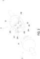
- FIG. 3 is a schematic view illustrating the connector of FIG. 1 taken from another viewpoint.
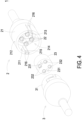
- FIG. 4 is a schematic exploded view illustrating the connector of FIG. 3 .
- the connector 1 of the present disclosure includes a socket connecting element 2 and a plug connecting element 3.
- the socket connecting element 2 includes a first main body 21, four first connecting terminals 22 and a first barrier 23.
- the first main body 21 is a hollow cylinder and includes an inner periphery surface 211, an outer periphery surface 212, a bottom 213, a first receiving portion 214 and two first guiding portions 215.
- the inner periphery surface 211 and the outer periphery surface 212 of the first main body 21 are opposite to each other.
- the outer periphery surface 212 of the first main body 21 is disposed around the inner periphery surface 211 of the first main body 21.
- the bottom 213 is connected with the inner periphery surface 211 and the outer periphery surface 212.
- the inner periphery surface 211 and the bottom 213 of the first main body 21 together define the first receiving portion 214.
- the opening of the first receiving portion 214 is toward the plug connecting element 3.
- the two first guiding portions 215 are extended from the inner periphery surface 211 of the first main body 21 and perpendicular to the inner periphery surface 211, respectively.
- the two first guiding portions 215 are disposed on the two opposite sides of the first main body 21 and disposed in the first receiving portion 214, respectively.
- the first main body 21 further includes a plurality of gaps 216.
- the first main body 21 includes four gaps 216. Each gap 216 is concavely formed from one side of the first main body 21 adjacent to the plug connecting element 3 away from the plug connecting element 3.
- Each first guiding portion 215 is disposed between the two corresponding gaps 216 so that the position of the first guiding portion 215 can be confirmed according to the position of the two gaps 216.
- Each first connecting terminal 22 is a conductive structure and extended from the bottom 213 of the first main body 21 toward the plug connecting element 3.
- the four first connecting terminals 22 are disposed around in sequence. Two of the four first connecting terminals 22 are disposed on the line formed between the two first guiding portions 215. One of the two first connecting terminals 22 disposed on the line formed between the two first guiding portions 215 is adjacent to one of the two first guiding portions 215. The other of the two first connecting terminals 22 disposed on the line formed between the two first guiding portions 215 is adjacent to the other of the two first guiding portions 215.
- the first barrier 23 is disposed in the first receiving portion 214 of the first main body 21 and fixed on the first main body 21.
- the first barrier 23 is fixed on the bottom 213 of the first main body 21 and covers the four first connecting terminals 22.
- the four first connecting terminals 22 are disposed on the bottom 213 of the first main body 213.
- the first barrier 23 includes two first aligning portions 231 and four first holes 232.
- the two first aligning portions 231 are disposed on one side of the first barrier 23 away from the bottom 213 of the first main body 21.
- the two first aligning portions 231 are disposed on one side of the first barrier 23 facing to the plug connecting element 3.
- each first aligning portion 231 is a concave structure.
- the four first holes 232 penetrates through the first barrier 23, respectively.
- the four first holes 232 and the four first connecting terminals 22 are spatially corresponding in position in a one-to-one relationship. Namely, each first connecting terminal 22 is exposed through the corresponding first hole 232.
- the plug connecting element 3 includes a second main body 31, four second connecting terminals 32 and a second barrier 33.
- the second main body 31 is a hollow cylinder and includes an inner periphery surface 311, an outer periphery surface 312, a bottom 313, a second receiving portion 314, two first paths 315 and two second paths 316.
- the inner periphery surface 311 and the outer periphery surface 312 of the second main body 31 are opposite to each other.
- the outer periphery surface 312 of the second main body 31 is disposed around the inner periphery surface 311 of the second main body 31.
- the diameter formed by the inner periphery surface 211 of the first main body 21 is greater than or equal to the diameter formed by the second outer periphery surface 312 of the second main body 31.
- the bottom 313 is connected with the inner periphery surface 311 and the outer periphery surface 312.
- the inner periphery surface 311 and the bottom 313 of the second main body 31 together define the second receiving portion 314.
- the opening of the second receiving portion 314 is toward the socket connecting element 2.
- the two first paths 315 are concavely formed from the outer periphery surface 312 of the second main body 31.
- the two first paths 315 are disposed on the two opposite sides of the second main body 31.
- the two first guiding portions 215 of the first main body 21 are aligned to and engaged with the corresponding first path 315, respectively, so as to drive the first main body 21 to rotate and/or move according to the track of the first path 315.
- each first path 315 of the second main body 31 includes a first interval 315a, a second interval 315b and a third interval 315c.
- the first interval 315a, the second interval 315b and the third interval 315c are disposed on the outer periphery surface 312 of the second main body 31 in sequence.
- a first end of the first interval 315a of the first path 315 is disposed on one end of the outer periphery surface 312 of the second main body 21 adjacent to the socket connecting element 2.
- the extension direction of the first interval 315a is the same as the axial direction of the second main body 31.
- a first end of the second interval 315b of the first path 315 is in communication with a second end of the first interval 315a of the first path 315.
- the extension direction of the second interval 315b is perpendicular to the extension direction of the first interval 315a.
- a first end of the third interval 315c of the first path 315 is in communication with a second end of the second interval 315b of the first path 315.
- the extension direction of the third interval 315c is the same as the extension direction of the first interval 315a. Namely, the extension direction of the third interval 315c is the same as the axial direction of the second main body 31.
- the two second paths 316 of the second main body 31 are concavely formed from the inner periphery surface 311 of the second main body 31, respectively.
- the two second paths 316 are disposed on the two opposite sides of the second main body 31.
- the track of each second path 316 and the track of the corresponding first path 315 are aligned to each other and disposed on the two opposite sides of the surface of the second main body 31.
- the second path 316 includes three intervals.
- Each interval of the second path 316 and the corresponding interval of the first path 315 are disposed on the two opposite sides of the surface of the second main body 31.
- the three intervals of the second path 316 are similar to the first interval 315a, the second interval 315b and the third interval 315c of the first path 315, respectively, and are not redundantly described hereinafter.
- Each second connecting terminal 32 is a conductive structure and extended from the bottom 313 of the second main body 31 toward the socket connecting element 2.
- the four second connecting terminals 32 are disposed around in sequence. Two of the four second connecting terminals 32 are adjacent to the intervals of the two second paths 316 corresponding to the third interval 315c of the first path 315, respectively.
- the second barrier 33 is disposed in the second receiving portion 314 of the second main body 31.
- the four second connecting terminals 32 are disposed on the bottom 313 of the second main body 31.
- the second barrier 33 includes two second aligning portions 331, four second holes 332 and two second guiding portions 333.
- the two second aligning portions 331 are disposed on one side of the second barrier 33 away from the bottom 313 of the second main body 31. Namely, the two second aligning portions 331 are disposed on one side of the second barrier 33 facing to the socket connecting element 2.
- each second aligning portion 331 is a protrusion structure.
- Each second aligning portion 331 is aligned to the corresponding first aligning portion 231 of the first barrier 23.
- the four second holes 332 penetrates through the second barrier 33, respectively.
- the four second holes 332 of the second barrier 33 and the four first holes 232 of the first barrier 23 are spatially corresponding in position in a one-to-one relationship.
- the two second guiding portions 333 are protruded from the outer periphery edge of the second barrier 33. Each second guiding portion 333 is aligned to the corresponding second path 316 so as to drive the second barrier 33 to rotate and/or move according to the track of the second path 316.
- the second guiding portion 333 of the second barrier 33 is disposed in the interval of the second path 316 of the second main body 31 corresponding to the first interval 315a of the first path 315, the four second connecting terminals 32 are covered by the second barrier 33 and cannot be exposed thorough the four second holes 332.
- the second guiding portion 33 of the second barrier 33 When the second guiding portion 33 of the second barrier 33 is disposed in the interval of the second path 316 of the second main body 31 corresponding to the third interval 315c of the first path 315, the four second connecting terminals 32 are exposed through the second hole 332, respectively.
- the operation of the second barrier 33 is described below.
- FIGS. 5A to 5D are schematic views illustrating an assembling process of the connector of FIG. 1 .
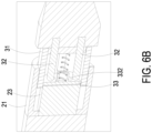
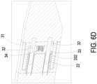
- FIGS. 6A to 6D are schematic cross-sectional views illustrating the connector of FIGS. 5A to 5D , respectively, and taken along the line A-A'.
- the first main body 21 of the socket connecting element 2 is contacted with the second main body 31 of the plug connecting element 3, and the first guiding portion 215 of the first main body 21 is aligned to one end of the first path 315 of the second main body 31 adjacent to the first main body 21.
- the first guiding portion 215 of the first main body 21 is placed at one end of the first interval 315a of the first path 315 adjacent to the first main body 21.
- the second connecting terminal 32 of the plug connecting element 3 is covered by the second barrier 33 and cannot be exposed through the four second holes 332.
- the first main body 21 of the socket connecting element 2 is moved toward the second main body 31 of the plug connecting element 3 along the axial direction of the first main body 21.
- the first guiding portion 215 of the first main body 21 is moved to the connection between the first interval 315a and the second interval 315b along the first interval 315a of the first path 315 of the second main body 31, so that the second aligning portion 331 of the second barrier 33 is aligned to and engaged with the first aligning portion 231 of the first barrier 23, and the four second holes 332 of the second barrier 33 and the four first holes 232 of the first barrier 23 are spatially corresponding in position in one-to-one relationship.
- the first barrier 23 is fixed on the first main body 21. Namely, when the first main body 21 drives the first barrier 23 to move, the first barrier 23 drives the second barrier 33 to move along the interval of the second path 316 of the second main body 31 corresponding to the first interval 315a of the first path 315. As shown in FIG. 6B , the second connecting terminal 32 of the plug connecting element 3 is covered by the second barrier 33 and cannot be exposed through the four second holes 332.
- the first main body 21 of the socket connecting element 2 is rotated along the second interval 315b of the plug connecting element 3.
- the first guiding portion 215 of the first main body 21 is moved to the connection between the second interval 315b and the third interval 315c along the second interval 315b of the first path 315 of the second main body 31.
- the first main body 21 drives the first barrier 23 to rotate, and the first barrier 23 drives the second barrier 33 to rotate in the same direction. Namely, the first barrier 23 drives the second barrier 33 to rotate along the interval of the second path 316 of the second main body 31 corresponding to the second interval 315b of the first path 315.
- each second connecting terminal 32 and the four second holes 332 are spatially in position in one-to-one relationship. Namely, each second connecting terminal 32 is exposed through the second hole 332. Consequently, the four second connecting terminals 32, the four second holes 332, the four first holes 232 and the four first connecting terminals 22 are spatially in position in one-to-one relationship in sequence. Namely, each second connecting terminal 32, the corresponding second hole 332, the corresponding first hole 232 and the corresponding first connecting terminal 22 are aligned in sequence.
- the first main body 21 of the socket connecting element 2 is moved toward the second main body 31 of the plug connecting element 3 along the axial direction of the first main body 21.
- the first guiding portion 215 of the first main body 21 is moved along the third interval 315c of the first path 315 of the second main body 31.
- the first main body 21 drives the first barrier 23 to move, and the first barrier 23 drives the second barrier 33 to move in the same direction.
- the first barrier 23 drives the second barrier 33 to move along the interval of the second path 316 of the second main body 31 corresponding to the third interval 315c of the first path 315. Consequently, each second connecting terminal 32 penetrates through the corresponding second hole 332 and the corresponding first hole 232 so as to contact with the corresponding first terminal 22.
- the plug connecting element 3 further includes a spring 34 disposed between the second barrier 33 and the bottom 313 of the second main body 31. Consequently, when the second connecting terminal 32 of the plug connecting element 3 is withdrawn from the first hole 232 of the first barrier 23, the spring 34 provides an elastic force to push the second barrier 33 back to its original position where the second barrier 33 is not forced by the first barrier 23.
- the connector of the present disclosure includes a first barrier and a second barrier.
- the plurality of first connecting terminals of the socket connecting element are disposed between the first barrier and the bottom of the first main body.
- the plurality of second connecting terminals of the plug connecting element are disposed between the second barrier and the bottom of the second main body.
- the plug connecting element When the plug connecting element is assembled with the socket connecting element, the first main body is rotated and moved, so that the second connecting terminal penetrates through the second hole of the second barrier to contact the first connecting terminal. Consequently, the safety of the connector of the present disclosure is enhanced, and the risk of user getting an electric shock is reduced.
Landscapes
- Details Of Connecting Devices For Male And Female Coupling (AREA)
- Connector Housings Or Holding Contact Members (AREA)
Abstract
Description
- The present disclosure relates to a connector, and more particularly to a connector having enhanced safety.
- Nowadays, the connector does not comprise a protect device. Consequently, the charged metal connecting terminal of the connector is directly contacted by user. Moreover, the market demand is increased, and the battery capacity of the electronic product is increased, so that the output voltage of the electronic product outputted from the connector is also increased. When the output voltage of the electronic product outputted from the connector is greater than 42V, it surpasses the safety regulation. Consequently, when the internal voltage protection of the electronic product is failed, the risk of user getting an electric shock is high for contacting the metal connecting terminal of the connector.
- Therefore, there is a need of providing a connector to obviate the drawbacks encountered from the prior arts.
- The present disclosure provides a connector. The connector of the present disclosure includes a first barrier and a second barrier. The plurality of first connecting terminals of the socket connecting element are disposed between the first barrier and the bottom of the first main body. The plurality of second connecting terminals of the plug connecting element are disposed between the second barrier and the bottom of the second main body. When the first main body is rotated and moved through the first path so as to drive the first barrier and the second barrier to rotate and move, the second connecting terminal penetrates through the second hole and the first hole so as to contact with the first connecting terminal. Consequently, when the plug connecting element is not assembled with the socket connecting element, the second barrier of the plug connecting element covers the second connecting terminal, and the second connecting terminal cannot be exposed so as to prevent user to contact with the second connecting terminal. When the plug connecting element is assembled with the socket connecting element, the first main body is rotated and moved, so that the second connecting terminal penetrates through the second hole of the second barrier to contact with the first connecting terminal. Consequently, the safety of the connector of the present disclosure is enhanced, and the risk of user getting an electric shock is reduced.
- In accordance with an aspect of the present disclosure, a connector is provided. The connector includes a socket connecting element and a plug connecting element. The socket connecting element includes a first main body, a first barrier and a plurality of first connecting terminals. An inner periphery surface of the first main body includes a first guiding portion. The first main body includes a first receiving portion. The first barrier is disposed in the first receiving portion and fixed on the first main body. The first barrier includes a first aligning portion and a plurality of first holes. The first aligning portion is disposed on one side of the first barrier away from a bottom of the first main body. The plurality of first holes and the plurality of first connecting terminals are spatially corresponding in position in one-to-one relationship. Each one of the plurality of first connecting terminals is disposed on the bottom of the first main body. The plug connecting element includes a second main body, a second barrier and a plurality of second connecting terminals. An outer periphery surface of the second main body includes a first path. The second main body includes a second receiving portion. The second barrier is disposed in the second receiving portion and includes a second aligning portion and a plurality of second holes. The second aligning portion is disposed on one side of the second barrier away from a bottom of the second main body. Each one of the plurality of second connecting terminals is disposed on the bottom of the second main body. The second aligning portion and the first aligning portion are aligned to each other, so that the plurality of second holes and the plurality of first holes are spatially corresponding in position in one-to-one relationship. The first guiding portion of the first main body is aligned to the first path of the second main body. The first main body is driven to be rotated and moved through a track of the first path. The first barrier and the second barrier are rotated and moved, so that each one of the plurality of second connecting terminals penetrates through corresponding one of the plurality of second holes and corresponding one of the plurality of first holes so as to contact with corresponding one of the first connecting terminal.
- The above contents of the present disclosure will become more readily apparent to those ordinarily skilled in the art after reviewing the following detailed description and accompanying drawings, in which:
-
-
FIG. 1 is a schematic view illustrating a connector of the present disclosure; -
FIG. 2 is a schematic exploded view illustrating the connector ofFIG. 1 ; -
FIG. 3 is a schematic view illustrating the connector ofFIG. 1 taken from another viewpoint; -
FIG. 4 is a schematic exploded view illustrating the connector ofFIG. 3 ; -
FIGS. 5A to 5D are schematic views illustrating an assembling process of the connector ofFIG. 1 ; and -
FIGS. 6A to 6D are schematic cross-sectional views illustrating the connector ofFIGS. 5A to 5D , respectively, and taken along the line A-A'. - The present disclosure will now be described more specifically with reference to the following embodiments. It is to be noted that the following descriptions of preferred embodiments of this disclosure are presented herein for purpose of illustration and description only. It is not intended to be exhaustive or to be limited to the precise form disclosed.
-
FIG. 1 is a schematic view illustrating a connector of the present disclosure.FIG. 2 is a schematic exploded view illustrating the connector ofFIG. 1 .FIG. 3 is a schematic view illustrating the connector ofFIG. 1 taken from another viewpoint.FIG. 4 is a schematic exploded view illustrating the connector ofFIG. 3 . As shown inFIGS. 1 to 4 , theconnector 1 of the present disclosure includes asocket connecting element 2 and aplug connecting element 3. - As shown in
FIGS. 3 and4 , thesocket connecting element 2 includes a firstmain body 21, four first connectingterminals 22 and afirst barrier 23. The firstmain body 21 is a hollow cylinder and includes aninner periphery surface 211, anouter periphery surface 212, abottom 213, a first receivingportion 214 and two first guidingportions 215. Theinner periphery surface 211 and theouter periphery surface 212 of the firstmain body 21 are opposite to each other. Theouter periphery surface 212 of the firstmain body 21 is disposed around theinner periphery surface 211 of the firstmain body 21. Thebottom 213 is connected with theinner periphery surface 211 and theouter periphery surface 212. Theinner periphery surface 211 and thebottom 213 of the firstmain body 21 together define the first receivingportion 214. The opening of the first receivingportion 214 is toward theplug connecting element 3. The twofirst guiding portions 215 are extended from theinner periphery surface 211 of the firstmain body 21 and perpendicular to theinner periphery surface 211, respectively. The twofirst guiding portions 215 are disposed on the two opposite sides of the firstmain body 21 and disposed in the first receivingportion 214, respectively. In this embodiment, the firstmain body 21 further includes a plurality ofgaps 216. For example, the firstmain body 21 includes fourgaps 216. Eachgap 216 is concavely formed from one side of the firstmain body 21 adjacent to theplug connecting element 3 away from theplug connecting element 3. Each first guidingportion 215 is disposed between the twocorresponding gaps 216 so that the position of thefirst guiding portion 215 can be confirmed according to the position of the twogaps 216. - Each first connecting
terminal 22 is a conductive structure and extended from thebottom 213 of the firstmain body 21 toward theplug connecting element 3. In this embodiment, the four first connectingterminals 22 are disposed around in sequence. Two of the four first connectingterminals 22 are disposed on the line formed between the twofirst guiding portions 215. One of the two first connectingterminals 22 disposed on the line formed between the twofirst guiding portions 215 is adjacent to one of the twofirst guiding portions 215. The other of the two first connectingterminals 22 disposed on the line formed between the twofirst guiding portions 215 is adjacent to the other of the twofirst guiding portions 215. - The
first barrier 23 is disposed in the first receivingportion 214 of the firstmain body 21 and fixed on the firstmain body 21. For example, thefirst barrier 23 is fixed on thebottom 213 of the firstmain body 21 and covers the four first connectingterminals 22. The four first connectingterminals 22 are disposed on thebottom 213 of the firstmain body 213. Thefirst barrier 23 includes two first aligningportions 231 and fourfirst holes 232. The two first aligningportions 231 are disposed on one side of thefirst barrier 23 away from thebottom 213 of the firstmain body 21. Namely, the two first aligningportions 231 are disposed on one side of thefirst barrier 23 facing to theplug connecting element 3. Preferably but not exclusively, each first aligningportion 231 is a concave structure. The fourfirst holes 232 penetrates through thefirst barrier 23, respectively. The fourfirst holes 232 and the four first connectingterminals 22 are spatially corresponding in position in a one-to-one relationship. Namely, each first connectingterminal 22 is exposed through the correspondingfirst hole 232. - As shown in
FIGS. 1 and2 , theplug connecting element 3 includes a secondmain body 31, four second connectingterminals 32 and asecond barrier 33. The secondmain body 31 is a hollow cylinder and includes aninner periphery surface 311, anouter periphery surface 312, a bottom 313, asecond receiving portion 314, twofirst paths 315 and twosecond paths 316. Theinner periphery surface 311 and theouter periphery surface 312 of the secondmain body 31 are opposite to each other. Theouter periphery surface 312 of the secondmain body 31 is disposed around theinner periphery surface 311 of the secondmain body 31. The diameter formed by theinner periphery surface 211 of the firstmain body 21 is greater than or equal to the diameter formed by the secondouter periphery surface 312 of the secondmain body 31. The bottom 313 is connected with theinner periphery surface 311 and theouter periphery surface 312. Theinner periphery surface 311 and thebottom 313 of the secondmain body 31 together define thesecond receiving portion 314. The opening of thesecond receiving portion 314 is toward thesocket connecting element 2. The twofirst paths 315 are concavely formed from theouter periphery surface 312 of the secondmain body 31. The twofirst paths 315 are disposed on the two opposite sides of the secondmain body 31. When thesocket connecting element 2 is assembled to theplug connecting element 3, the twofirst guiding portions 215 of the firstmain body 21 are aligned to and engaged with the correspondingfirst path 315, respectively, so as to drive the firstmain body 21 to rotate and/or move according to the track of thefirst path 315. - In this embodiment, as shown in
FIGS. 1 and2 , eachfirst path 315 of the secondmain body 31 includes afirst interval 315a, asecond interval 315b and athird interval 315c. Thefirst interval 315a, thesecond interval 315b and thethird interval 315c are disposed on theouter periphery surface 312 of the secondmain body 31 in sequence. A first end of thefirst interval 315a of thefirst path 315 is disposed on one end of theouter periphery surface 312 of the secondmain body 21 adjacent to thesocket connecting element 2. The extension direction of thefirst interval 315a is the same as the axial direction of the secondmain body 31. A first end of thesecond interval 315b of thefirst path 315 is in communication with a second end of thefirst interval 315a of thefirst path 315. The extension direction of thesecond interval 315b is perpendicular to the extension direction of thefirst interval 315a. A first end of thethird interval 315c of thefirst path 315 is in communication with a second end of thesecond interval 315b of thefirst path 315. The extension direction of thethird interval 315c is the same as the extension direction of thefirst interval 315a. Namely, the extension direction of thethird interval 315c is the same as the axial direction of the secondmain body 31. - The two
second paths 316 of the secondmain body 31 are concavely formed from theinner periphery surface 311 of the secondmain body 31, respectively. The twosecond paths 316 are disposed on the two opposite sides of the secondmain body 31. The track of eachsecond path 316 and the track of the correspondingfirst path 315 are aligned to each other and disposed on the two opposite sides of the surface of the secondmain body 31. Namely, thesecond path 316 includes three intervals. Each interval of thesecond path 316 and the corresponding interval of thefirst path 315 are disposed on the two opposite sides of the surface of the secondmain body 31. For example, the three intervals of thesecond path 316 are similar to thefirst interval 315a, thesecond interval 315b and thethird interval 315c of thefirst path 315, respectively, and are not redundantly described hereinafter. - Each second connecting
terminal 32 is a conductive structure and extended from thebottom 313 of the secondmain body 31 toward thesocket connecting element 2. In this embodiment, the four second connectingterminals 32 are disposed around in sequence. Two of the four second connectingterminals 32 are adjacent to the intervals of the twosecond paths 316 corresponding to thethird interval 315c of thefirst path 315, respectively. - The
second barrier 33 is disposed in thesecond receiving portion 314 of the secondmain body 31. The four second connectingterminals 32 are disposed on thebottom 313 of the secondmain body 31. Thesecond barrier 33 includes two second aligningportions 331, foursecond holes 332 and twosecond guiding portions 333. The two second aligningportions 331 are disposed on one side of thesecond barrier 33 away from thebottom 313 of the secondmain body 31. Namely, the two second aligningportions 331 are disposed on one side of thesecond barrier 33 facing to thesocket connecting element 2. Preferably but not exclusively, each second aligningportion 331 is a protrusion structure. Each second aligningportion 331 is aligned to the corresponding first aligningportion 231 of thefirst barrier 23. The foursecond holes 332 penetrates through thesecond barrier 33, respectively. When thesocket connecting element 2 is assembled to theplug connecting element 3 and the second aligningportion 331 is aligned to the first aligningportion 231, the foursecond holes 332 of thesecond barrier 33 and the fourfirst holes 232 of thefirst barrier 23 are spatially corresponding in position in a one-to-one relationship. - The two
second guiding portions 333 are protruded from the outer periphery edge of thesecond barrier 33. Eachsecond guiding portion 333 is aligned to the correspondingsecond path 316 so as to drive thesecond barrier 33 to rotate and/or move according to the track of thesecond path 316. When thesecond guiding portion 333 of thesecond barrier 33 is disposed in the interval of thesecond path 316 of the secondmain body 31 corresponding to thefirst interval 315a of thefirst path 315, the four second connectingterminals 32 are covered by thesecond barrier 33 and cannot be exposed thorough the foursecond holes 332. When the second guidingportion 33 of thesecond barrier 33 is disposed in the interval of thesecond path 316 of the secondmain body 31 corresponding to thethird interval 315c of thefirst path 315, the four second connectingterminals 32 are exposed through thesecond hole 332, respectively. The operation of thesecond barrier 33 is described below. -
FIGS. 5A to 5D are schematic views illustrating an assembling process of the connector ofFIG. 1 .FIGS. 6A to 6D are schematic cross-sectional views illustrating the connector ofFIGS. 5A to 5D , respectively, and taken along the line A-A'. As shown inFIGS. 5A and6A , the firstmain body 21 of thesocket connecting element 2 is contacted with the secondmain body 31 of theplug connecting element 3, and thefirst guiding portion 215 of the firstmain body 21 is aligned to one end of thefirst path 315 of the secondmain body 31 adjacent to the firstmain body 21. Namely, thefirst guiding portion 215 of the firstmain body 21 is placed at one end of thefirst interval 315a of thefirst path 315 adjacent to the firstmain body 21. As shown inFIG. 6A , the second connectingterminal 32 of theplug connecting element 3 is covered by thesecond barrier 33 and cannot be exposed through the foursecond holes 332. - Then, as shown in
FIGS. 2 ,5B and6B , the firstmain body 21 of thesocket connecting element 2 is moved toward the secondmain body 31 of theplug connecting element 3 along the axial direction of the firstmain body 21. Thefirst guiding portion 215 of the firstmain body 21 is moved to the connection between thefirst interval 315a and thesecond interval 315b along thefirst interval 315a of thefirst path 315 of the secondmain body 31, so that the second aligningportion 331 of thesecond barrier 33 is aligned to and engaged with the first aligningportion 231 of thefirst barrier 23, and the foursecond holes 332 of thesecond barrier 33 and the fourfirst holes 232 of thefirst barrier 23 are spatially corresponding in position in one-to-one relationship. Thefirst barrier 23 is fixed on the firstmain body 21. Namely, when the firstmain body 21 drives thefirst barrier 23 to move, thefirst barrier 23 drives thesecond barrier 33 to move along the interval of thesecond path 316 of the secondmain body 31 corresponding to thefirst interval 315a of thefirst path 315. As shown inFIG. 6B , the second connectingterminal 32 of theplug connecting element 3 is covered by thesecond barrier 33 and cannot be exposed through the foursecond holes 332. - Then, as shown in
FIGS. 2 ,5C and6C , the firstmain body 21 of thesocket connecting element 2 is rotated along thesecond interval 315b of theplug connecting element 3. In more detail, thefirst guiding portion 215 of the firstmain body 21 is moved to the connection between thesecond interval 315b and thethird interval 315c along thesecond interval 315b of thefirst path 315 of the secondmain body 31. The firstmain body 21 drives thefirst barrier 23 to rotate, and thefirst barrier 23 drives thesecond barrier 33 to rotate in the same direction. Namely, thefirst barrier 23 drives thesecond barrier 33 to rotate along the interval of thesecond path 316 of the secondmain body 31 corresponding to thesecond interval 315b of thefirst path 315. Consequently, the four second connectingterminals 32 and the foursecond holes 332 are spatially in position in one-to-one relationship. Namely, each second connectingterminal 32 is exposed through thesecond hole 332. Consequently, the four second connectingterminals 32, the foursecond holes 332, the fourfirst holes 232 and the four first connectingterminals 22 are spatially in position in one-to-one relationship in sequence. Namely, each second connectingterminal 32, the correspondingsecond hole 332, the correspondingfirst hole 232 and the corresponding first connectingterminal 22 are aligned in sequence. - Then, as shown in
FIGS. 2 ,5D and6D , the firstmain body 21 of thesocket connecting element 2 is moved toward the secondmain body 31 of theplug connecting element 3 along the axial direction of the firstmain body 21. Thefirst guiding portion 215 of the firstmain body 21 is moved along thethird interval 315c of thefirst path 315 of the secondmain body 31. The firstmain body 21 drives thefirst barrier 23 to move, and thefirst barrier 23 drives thesecond barrier 33 to move in the same direction. Namely, thefirst barrier 23 drives thesecond barrier 33 to move along the interval of thesecond path 316 of the secondmain body 31 corresponding to thethird interval 315c of thefirst path 315. Consequently, each second connectingterminal 32 penetrates through the correspondingsecond hole 332 and the correspondingfirst hole 232 so as to contact with the correspondingfirst terminal 22. - Please refer to
FIGS. 6C and6D , theplug connecting element 3 further includes aspring 34 disposed between thesecond barrier 33 and thebottom 313 of the secondmain body 31. Consequently, when the second connectingterminal 32 of theplug connecting element 3 is withdrawn from thefirst hole 232 of thefirst barrier 23, thespring 34 provides an elastic force to push thesecond barrier 33 back to its original position where thesecond barrier 33 is not forced by thefirst barrier 23. - As mentioned above, the connector of the present disclosure includes a first barrier and a second barrier. The plurality of first connecting terminals of the socket connecting element are disposed between the first barrier and the bottom of the first main body. The plurality of second connecting terminals of the plug connecting element are disposed between the second barrier and the bottom of the second main body. When the first main body is rotated and moved through the first path so as to drive the first barrier and the second barrier to rotate and move, the second connecting terminal penetrates through the second hole and the first hole so as to contact with the first connecting terminal. Consequently, when the plug connecting element is not assembled with the socket connecting element, the second barrier of the plug connecting element covers the second connecting terminal, and the second connecting terminal cannot be exposed so as to prevent user to contact the second connecting terminal. When the plug connecting element is assembled with the socket connecting element, the first main body is rotated and moved, so that the second connecting terminal penetrates through the second hole of the second barrier to contact the first connecting terminal. Consequently, the safety of the connector of the present disclosure is enhanced, and the risk of user getting an electric shock is reduced.
Claims (10)
- A connector (1), characterized by comprising:a socket connecting element (2) comprising a first main body (21), a first barrier (23) and a plurality of first connecting terminals (22), wherein an inner periphery surface (211) of the first main body (21) comprises a first guiding portion (215), the first main body (21) comprises a first receiving portion (214), the first barrier (23) is disposed in the first receiving portion (214) and fixed on the first main body (21), the first barrier (23) comprises a first aligning portion (231) and a plurality of first holes (232), the first aligning portion (231) is disposed on one side of the first barrier (23) away from a bottom (213) of the first main body (21), the plurality of first holes (232) and the plurality of first connecting terminals (22) are spatially corresponding in position in one-to-one relationship, and each one of the plurality of first connecting terminals (22) is disposed on the bottom (213) of the first main body (21); anda plug connecting element (3) comprising a second main body (31), a second barrier (33) and a plurality of second connecting terminals (32), wherein an outer periphery surface (312) of the second main body (31) comprises a first path (315), the second main body (31) comprises a second receiving portion (314), the second barrier (33) is disposed in the second receiving portion (314) and comprises a second aligning portion (331) and a plurality of second holes (332), the second aligning portion (331) is disposed on one side of the second barrier (33) away from a bottom (313) of the second main body (31), and each one of the plurality of second connecting terminals (32) is disposed on the second main body (31), wherein the second aligning portion (331) and the first aligning portion (231) are aligned to each other, so that the plurality of second holes (332) and the plurality of first holes (232) are spatially corresponding in position in one-to-one relationship, the first guiding portion (215) of the first main body (21) is aligned to the first path (315) of the second main body (31), the first main body (21) is driven to be rotated and moved through a track of the first path (315), and the first barrier (23) and the second barrier (33) are rotated and moved, so that each one of the plurality of second connecting terminals (32) penetrates through corresponding one of the plurality of second holes (332) and corresponding one of the plurality of first holes (232) so as to contact with corresponding one of the plurality of first connecting terminals (22).
- The connector (1) according to claim 1, wherein the first path (315) comprises a first interval (315a), a second interval (315b) and a third interval (315c), a first end of the first interval (315a) is disposed on one end of the second main body (31) adjacent to the first main body (21), an extension direction of the first interval (315a) is the same as an axial direction of the second main body (31), the second interval (315b) is disposed between a second end of the second interval (315b) and one end of the third interval (315c), an extension direction of the second interval (315b) is perpendicular to the extension direction of the first interval (315a), and an extension direction of the third interval (315c) is the same as the extension direction of the first interval (315a).
- The connector (1) according to claim 2, wherein the second barrier (33) of the plug connecting element (3) comprises a second guiding portion (333) protruded from an outer periphery edge of the second barrier (33), the second main body (31) comprises a second path (316) concavely formed from an inner periphery surface (311) of the second main body (31), and the second guiding portion (333) is aligned to the second path (316) and drives the second barrier (33) to rotate and move according to a track of the second path (316).
- The connector (1) according to claim 3, wherein the track of the second path (316) of the second main body (31) and the track of the first path (315) of the second main body (31) are aligned to each other and disposed on the two opposite sides of a surface of the second main body (31).
- The connector (1) according to any one of claims 3 and 4, wherein one of the plurality of second connecting terminals (32) is adjacent to an interval of the second path (316) corresponding to the third interval (315c) of the first path (315).
- The connector (1) according to any one of claims 3 and 4, wherein when the second guiding portion (333) of the second barrier (33) is disposed in an interval of the second path (316) corresponding to the first interval (315a) of the first path (315), the plurality of second connecting terminals (32) are covered by the second barrier (33) and cannot be exposed through the plurality of second holes (332), wherein when the second guiding portion (333) of the second barrier (33) is disposed in the interval of the second path (316) corresponding to the third interval (315c) of the first path (315), the plurality of second connecting terminals (32) are exposed through corresponding one of the plurality of second holes (332), respectively.
- The connector (1) according to any one of claims 1 to 6, wherein one of the plurality of first connecting terminals (22) is adjacent to the first guiding portion (215).
- The connector (1) according to any one of claims 1 to 7, wherein the first main body (21) of the socket connecting element (2) comprises two gaps (216), each of the two gaps (216) is concavely formed from one side of the first main body (21) adjacent to the second main body (31) and away from the second main body (31), wherein the first guiding portion (215) is disposed between the two gaps (216).
- The connector (1) according to any one of claims 1 to 8, wherein a diameter formed by the inner periphery surface (211) of the first main body (21) is greater than or equal to a diameter formed by the outer periphery surface of the second main body (31).
- The connector (1) according to any one of claims 1 to 9, wherein the plug connecting element (3) comprises a spring (34) disposed between the first barrier (23) and the bottom (313) of the second main body (31).
Applications Claiming Priority (1)
| Application Number | Priority Date | Filing Date | Title |
|---|---|---|---|
| CN202311622150.1A CN120073384A (en) | 2023-11-29 | 2023-11-29 | Connector with a plurality of connectors |
Publications (2)
| Publication Number | Publication Date |
|---|---|
| EP4564614A1 true EP4564614A1 (en) | 2025-06-04 |
| EP4564614B1 EP4564614B1 (en) | 2026-04-08 |
Family
ID=90140563
Family Applications (1)
| Application Number | Title | Priority Date | Filing Date |
|---|---|---|---|
| EP24161455.1A Active EP4564614B1 (en) | 2023-11-29 | 2024-03-05 | Connector |
Country Status (3)
| Country | Link |
|---|---|
| US (1) | US20250174928A1 (en) |
| EP (1) | EP4564614B1 (en) |
| CN (1) | CN120073384A (en) |
Citations (2)
| Publication number | Priority date | Publication date | Assignee | Title |
|---|---|---|---|---|
| DE615452C (en) * | 1929-04-09 | 1935-07-05 | Siemens Schuckertwerke Akt Ges | Connector with an insulating washer that moves in front of the live contact sleeves when the connector is pulled out |
| EP0665454A1 (en) * | 1994-02-01 | 1995-08-02 | Hirose Electric Co., Ltd. | Connector |
Family Cites Families (7)
| Publication number | Priority date | Publication date | Assignee | Title |
|---|---|---|---|---|
| JP2009037986A (en) * | 2007-08-03 | 2009-02-19 | Smk Corp | Connector |
| US7632126B1 (en) * | 2008-05-23 | 2009-12-15 | Tyco Electronics Corporation | High density circular interconnect with bayonet action |
| EP3288124B1 (en) * | 2015-04-21 | 2021-09-08 | Witco Of Jupiter Dentsu Co., Ltd. | Connector |
| EP3522309B1 (en) * | 2018-02-06 | 2021-01-06 | Witco Of Jupiter Dentsu Co., Ltd. | Connector |
| US10559916B1 (en) * | 2018-08-07 | 2020-02-11 | Delta Electronics, Inc. | Adapter assembly |
| CN112838432B (en) * | 2019-11-07 | 2022-12-20 | 台达电子工业股份有限公司 | Power Adapter Module |
| TWI728578B (en) * | 2019-11-28 | 2021-05-21 | 劉達民 | Quick joint structure with pressing and rotating lock/unlock |
-
2023
- 2023-11-29 CN CN202311622150.1A patent/CN120073384A/en active Pending
-
2024
- 2024-02-22 US US18/584,337 patent/US20250174928A1/en active Pending
- 2024-03-05 EP EP24161455.1A patent/EP4564614B1/en active Active
Patent Citations (2)
| Publication number | Priority date | Publication date | Assignee | Title |
|---|---|---|---|---|
| DE615452C (en) * | 1929-04-09 | 1935-07-05 | Siemens Schuckertwerke Akt Ges | Connector with an insulating washer that moves in front of the live contact sleeves when the connector is pulled out |
| EP0665454A1 (en) * | 1994-02-01 | 1995-08-02 | Hirose Electric Co., Ltd. | Connector |
Also Published As
| Publication number | Publication date |
|---|---|
| CN120073384A (en) | 2025-05-30 |
| US20250174928A1 (en) | 2025-05-29 |
| EP4564614B1 (en) | 2026-04-08 |
Similar Documents
| Publication | Publication Date | Title |
|---|---|---|
| US11749926B2 (en) | Electrical connection device for vehicle | |
| US11901678B2 (en) | Contact member for electrical connector | |
| US8734173B2 (en) | Connector | |
| US9705229B2 (en) | Connector assembly | |
| CN105612672B (en) | Coaxial connector with floating mechanism | |
| US11177602B2 (en) | Female terminal | |
| US20110028033A1 (en) | Coaxial connector and connector device | |
| US9831597B2 (en) | Flexible and breakaway mechanisms for connectors | |
| KR102932935B1 (en) | connector assembly | |
| WO2021090698A1 (en) | Connector | |
| KR102356882B1 (en) | Pogopins for transmitting signal | |
| EP4564614B1 (en) | Connector | |
| JP2025157412A (en) | Female terminal and main terminal body | |
| US9088089B2 (en) | Power connector assembly | |
| US6109949A (en) | Connector assembly including a header connector and a socket connector | |
| WO2023140029A1 (en) | Connection terminal | |
| CN111106478A (en) | Electric connector | |
| CN112134051A (en) | Board End Connectors and Connector Assemblies | |
| JP7691726B2 (en) | connector | |
| US11824288B2 (en) | Cable connection device | |
| US20250112407A1 (en) | Electrical connection system, plug, and receptacle | |
| TWI852850B (en) | Connector | |
| JP2020035642A (en) | Electric connection connector | |
| JP2514775Y2 (en) | Connector with chip type electric components | |
| CN217387552U (en) | Electrical connector |
Legal Events
| Date | Code | Title | Description |
|---|---|---|---|
| PUAI | Public reference made under article 153(3) epc to a published international application that has entered the european phase |
Free format text: ORIGINAL CODE: 0009012 |
|
| STAA | Information on the status of an ep patent application or granted ep patent |
Free format text: STATUS: REQUEST FOR EXAMINATION WAS MADE |
|
| 17P | Request for examination filed |
Effective date: 20241007 |
|
| AK | Designated contracting states |
Kind code of ref document: A1 Designated state(s): AL AT BE BG CH CY CZ DE DK EE ES FI FR GB GR HR HU IE IS IT LI LT LU LV MC ME MK MT NL NO PL PT RO RS SE SI SK SM TR |
|
| GRAP | Despatch of communication of intention to grant a patent |
Free format text: ORIGINAL CODE: EPIDOSNIGR1 |
|
| STAA | Information on the status of an ep patent application or granted ep patent |
Free format text: STATUS: GRANT OF PATENT IS INTENDED |
|
| RIC1 | Information provided on ipc code assigned before grant |
Ipc: H01R 13/453 20060101AFI20251001BHEP Ipc: H01R 24/28 20110101ALN20251001BHEP Ipc: H01R 24/20 20110101ALN20251001BHEP Ipc: H01R 13/625 20060101ALN20251001BHEP Ipc: H01R 13/627 20060101ALN20251001BHEP |
|
| INTG | Intention to grant announced |
Effective date: 20251010 |
|
| GRAS | Grant fee paid |
Free format text: ORIGINAL CODE: EPIDOSNIGR3 |
|
| GRAA | (expected) grant |
Free format text: ORIGINAL CODE: 0009210 |
|
| STAA | Information on the status of an ep patent application or granted ep patent |
Free format text: STATUS: THE PATENT HAS BEEN GRANTED |
|
| AK | Designated contracting states |
Kind code of ref document: B1 Designated state(s): AL AT BE BG CH CY CZ DE DK EE ES FI FR GB GR HR HU IE IS IT LI LT LU LV MC ME MK MT NL NO PL PT RO RS SE SI SK SM TR |
|
| REG | Reference to a national code |
Ref country code: CH Ref legal event code: F10 Free format text: ST27 STATUS EVENT CODE: U-0-0-F10-F00 (AS PROVIDED BY THE NATIONAL OFFICE) Effective date: 20260408 Ref country code: GB Ref legal event code: FG4D |
|
| REG | Reference to a national code |
Ref country code: DE Ref legal event code: R096 Ref document number: 602024003725 Country of ref document: DE |