EP4564582A1 - Electrode assembly, battery cell, battery, and electric device - Google Patents
Electrode assembly, battery cell, battery, and electric device Download PDFInfo
- Publication number
- EP4564582A1 EP4564582A1 EP22959913.9A EP22959913A EP4564582A1 EP 4564582 A1 EP4564582 A1 EP 4564582A1 EP 22959913 A EP22959913 A EP 22959913A EP 4564582 A1 EP4564582 A1 EP 4564582A1
- Authority
- EP
- European Patent Office
- Prior art keywords
- tab
- electrode assembly
- battery
- bent portion
- electrode
- Prior art date
- Legal status (The legal status is an assumption and is not a legal conclusion. Google has not performed a legal analysis and makes no representation as to the accuracy of the status listed.)
- Pending
Links
Images


Classifications
-
- H—ELECTRICITY
- H01—ELECTRIC ELEMENTS
- H01M—PROCESSES OR MEANS, e.g. BATTERIES, FOR THE DIRECT CONVERSION OF CHEMICAL ENERGY INTO ELECTRICAL ENERGY
- H01M50/00—Constructional details or processes of manufacture of the non-active parts of electrochemical cells other than fuel cells, e.g. hybrid cells
- H01M50/50—Current conducting connections for cells or batteries
- H01M50/531—Electrode connections inside a battery casing
- H01M50/533—Electrode connections inside a battery casing characterised by the shape of the leads or tabs
-
- H—ELECTRICITY
- H01—ELECTRIC ELEMENTS
- H01M—PROCESSES OR MEANS, e.g. BATTERIES, FOR THE DIRECT CONVERSION OF CHEMICAL ENERGY INTO ELECTRICAL ENERGY
- H01M50/00—Constructional details or processes of manufacture of the non-active parts of electrochemical cells other than fuel cells, e.g. hybrid cells
- H01M50/50—Current conducting connections for cells or batteries
- H01M50/531—Electrode connections inside a battery casing
- H01M50/536—Electrode connections inside a battery casing characterised by the method of fixing the leads to the electrodes, e.g. by welding
-
- H—ELECTRICITY
- H01—ELECTRIC ELEMENTS
- H01M—PROCESSES OR MEANS, e.g. BATTERIES, FOR THE DIRECT CONVERSION OF CHEMICAL ENERGY INTO ELECTRICAL ENERGY
- H01M50/00—Constructional details or processes of manufacture of the non-active parts of electrochemical cells other than fuel cells, e.g. hybrid cells
- H01M50/50—Current conducting connections for cells or batteries
- H01M50/531—Electrode connections inside a battery casing
- H01M50/54—Connection of several leads or tabs of plate-like electrode stacks, e.g. electrode pole straps or bridges
-
- H—ELECTRICITY
- H01—ELECTRIC ELEMENTS
- H01M—PROCESSES OR MEANS, e.g. BATTERIES, FOR THE DIRECT CONVERSION OF CHEMICAL ENERGY INTO ELECTRICAL ENERGY
- H01M50/00—Constructional details or processes of manufacture of the non-active parts of electrochemical cells other than fuel cells, e.g. hybrid cells
- H01M50/50—Current conducting connections for cells or batteries
- H01M50/543—Terminals
- H01M50/552—Terminals characterised by their shape
- H01M50/553—Terminals adapted for prismatic, pouch or rectangular cells
- H01M50/557—Plate-shaped terminals
-
- H—ELECTRICITY
- H01—ELECTRIC ELEMENTS
- H01M—PROCESSES OR MEANS, e.g. BATTERIES, FOR THE DIRECT CONVERSION OF CHEMICAL ENERGY INTO ELECTRICAL ENERGY
- H01M50/00—Constructional details or processes of manufacture of the non-active parts of electrochemical cells other than fuel cells, e.g. hybrid cells
- H01M50/50—Current conducting connections for cells or batteries
- H01M50/543—Terminals
- H01M50/564—Terminals characterised by their manufacturing process
- H01M50/566—Terminals characterised by their manufacturing process by welding, soldering or brazing
-
- H—ELECTRICITY
- H01—ELECTRIC ELEMENTS
- H01M—PROCESSES OR MEANS, e.g. BATTERIES, FOR THE DIRECT CONVERSION OF CHEMICAL ENERGY INTO ELECTRICAL ENERGY
- H01M2220/00—Batteries for particular applications
- H01M2220/20—Batteries in motive systems, e.g. vehicle, ship, plane
-
- Y—GENERAL TAGGING OF NEW TECHNOLOGICAL DEVELOPMENTS; GENERAL TAGGING OF CROSS-SECTIONAL TECHNOLOGIES SPANNING OVER SEVERAL SECTIONS OF THE IPC; TECHNICAL SUBJECTS COVERED BY FORMER USPC CROSS-REFERENCE ART COLLECTIONS [XRACs] AND DIGESTS
- Y02—TECHNOLOGIES OR APPLICATIONS FOR MITIGATION OR ADAPTATION AGAINST CLIMATE CHANGE
- Y02E—REDUCTION OF GREENHOUSE GAS [GHG] EMISSIONS, RELATED TO ENERGY GENERATION, TRANSMISSION OR DISTRIBUTION
- Y02E60/00—Enabling technologies; Technologies with a potential or indirect contribution to GHG emissions mitigation
- Y02E60/10—Energy storage using batteries
Definitions
- the present application relates to the technical field of batteries, and in particular to an electrode assembly, a battery cell, a battery, and an electrical apparatus.
- the present application provides an electrode assembly, a battery cell, a battery, and an electrical apparatus, which can improve the reliability of the battery.
- an electrode assembly including: an electrode plate; and a tab, the tab being arranged at an end of the electrode plate in a first direction, the tab being provided with a bent portion, and the bent portion being used for providing stretching space for the tab.
- the tab in the bent portion can stretch out when the electrode assembly expands, providing the stretching space for the tab. Even when the thickness of the electrode assembly expands to twice its initial state, the electrical connection of the tab can still be maintained, and the tab is prevented from being cracked or even broken by being pulled due to excessive expansion of the thickness of the electrode assembly, thereby improving the reliability of the battery.
- the overall length of the electrode assembly with the bent portion remains unchanged, without occupying additional space, so that the energy density of the battery cell can be ensured; meanwhile, the bent portion can provide a larger stretching space so as to be applicable to an electrode assembly with a greater degree of expansion.
- the bent portion includes at least one bent structure.
- the bent structure enables the folding of the length of the tab to provide additional stretching space for the tab when the electrode assembly expands, so that the tab is prevented from being cracked or even broken by being pulled due to excessive expansion of the thickness of the electrode assembly.
- the bent structure is at least one of a sawtooth shape, an arc shape, and a square wave shape.
- Bent structures of different shapes can provide stretching space for the tab, so that the tab is prevented from being cracked or even broken by being pulled due to excessive expansion of the thickness of the electrode assembly.
- the bent portion formed by a sawtooth-shaped bent structure allows more parts of the tab to be folded, providing more stretching space for the tab. Meanwhile, even when the bent portion has been formed, the length of the tab in the first direction can still be adjusted by adjusting the angle in the sawtooth shape, which is beneficial for controlling the overall length of the electrode assembly in the first direction, thereby preventing the electrode assembly from occupying additional space in the first direction, and ensuring the energy density of the battery cell.
- the bent portion includes a plurality of fold surfaces sequentially connected along the first direction, and an angle between two adjacent fold surfaces is in the range from 30° to 120°.
- the appropriate angle range can not only allow the stretching space required by the tab when the electrode assembly expands, but also cause no damage to the tab and the electrode assembly, which is beneficial for prolonging the service life of the battery cell.
- the bent portion protrudes from the plane in which the tab is located in the second direction.
- the folding of a part of the tab can be realized to provide additional stretching space for the tab when the electrode assembly expands, so that the tab is prevented from being cracked or even broken by being pulled due to excessive expansion of the thickness of the electrode assembly.
- a projection of the bent portion in the first direction has a size in the second direction that is in the range from 0.3 to 2 mm.
- the appropriate size range can allow the stretching space required by the tab when the electrode assembly expands without taking up too much additional space, which is beneficial for improving the energy density of the battery cell.
- a plurality of the tabs are overlapped together to form a connecting region, and the bent portion is arranged in the connecting region.
- Arranging the bent portion in the connecting region can ensure that each tab can be provided with a bent portion, which can provide stretching space for the tab when the thickness of the electrode assembly expands significantly without affecting the subsequent welding of the tab lead to the tab, thereby ensuring the reliability of the battery during use of the battery.
- a maximum length of the tab after extension is F
- a thickness of the electrode assembly in the second direction is E
- a distance between the end of the connecting region facing away from the electrode plate and the electrode plate is D
- D, E and F satisfy the following relational expression: F > D 2 + E 2 .
- a length to be folded can be reserved for the tab, so as to ensure the electrical connection of the tab when the electrode assembly expands, so that the tab is prevented from being cracked or even broken by being pulled due to excessive expansion of the thickness of the electrode assembly.
- the electrode assembly further includes: an electrode lead, an end of the electrode lead being welded to the end of the connecting region facing away from the electrode plate in the first direction.
- the electrode lead can lead the current out of the inside of the electrode assembly, thereby realizing the function of the battery cell to provide electrical energy. Meanwhile, welding the electrode lead to one end of the connecting region can also ensure the connection strength of the tab at this end of the connecting region, so that the tab is prevented from falling off due to the expansion of the electrode assembly, ensuring good electrical connection of the tab, and consequently improving the reliability of the battery.
- the bent portion is formed by a pressing plate with a bent surface under a pressure in the range from 10 to 500 kPa.
- the pressing plate with the bent surface can efficiently form a bent portion on the surface of the tab to provide stretching space for the tab when the electrode assembly expands, so that the tab is prevented from being cracked or even broken by being pulled due to excessive expansion of the thickness of the electrode assembly, thereby improving the reliability of the battery. Meanwhile, forming the bent portion under an appropriate pressure can also improve the yield of the products, thereby improving production efficiency.
- the tabs include a first tab and a second tab, the first tab and the second tab have opposite polarities, a plurality of the first tabs are overlapped together to form a first connecting region, a plurality of the second tabs are overlapped together to form a second connecting region, and the first connecting region and the second connecting region are respectively provided with a bent portion.
- both tabs can be protected, the electrical connection of the tabs is maintained when the electrode assembly expands, and the tabs are prevented from being cracked or even broken by being pulled due to excessive expansion of the thickness of the electrode assembly, thereby improving the reliability of the battery.
- a battery cell including the electrode assembly of any one of the above embodiments.
- a battery including the battery cell of any one of the above embodiments.
- an electrical apparatus including the battery of any one of the above embodiments, and the battery is used for providing electric energy for the electrical apparatus.
- the term "and/or" is only an association relationship for describing associated objects, indicating that there may be three relationships, for example, the expression A and/or B may represent three situations: A exists alone, both A and B exist, and B exists alone.
- the character "/" in the present application generally means that the associated objects before and after it are in an "or" relationship.
- a plurality of means two or more (including two), similarly, “a plurality of groups” means two or more groups (including two groups), and “a plurality of sheets” means two or more sheets (including two sheets).
- the same reference numerals indicate the same components and, for the sake of brevity, the detailed description of the same components is omitted in the different embodiments. It should be understood that the thickness, length, width and other dimensions of the various components in the embodiments of the present application shown in the drawings, as well as the overall thickness, length, width and other dimensions of an integrated apparatus, are for illustrative purposes only, and should not constitute any limitation to the present application.
- the battery cell may include a lithium-ion secondary battery, a lithium-ion primary battery, a lithium sulfur battery, a sodium/lithium-ion battery, a sodium-ion battery, a lithium metal battery or a magnesium-ion battery and so on. This is not limited in the embodiments of the present application.
- the battery cell may be in a cylindrical shape, a flat shape, a cuboid shape or another shape, which is not limited in the embodiments of the present application either.
- the battery cells are generally classified into three types depending on the way of package: cylindrical battery cells, prismatic battery cells and pouch battery cells, which are also not limited in the embodiments of the present application.
- the battery mentioned in the embodiments of the present application refers to a single physical module including one or more battery cells to provide a higher voltage and capacity.
- the battery mentioned in the present application may include a battery module or a battery pack, etc.
- the battery generally includes a box for packaging one or more battery cells. The box can prevent liquid or other foreign matters from affecting charging or discharging of the battery cells.
- the battery cell includes an electrode assembly and an electrolyte solution, the electrode assembly being composed of a positive electrode plate, a negative electrode plate and a separator.
- the battery cell operates mainly relying on the movement of metal ions between the positive electrode plate and the negative electrode plate.
- the positive electrode plate includes a positive electrode current collector and a positive electrode active material layer.
- the positive electrode active material layer is coated on the surface of the positive electrode current collector. The parts of the positive electrode current collector not coated with the positive electrode active material layer protrude from the parts of the positive electrode current collector coated with the positive electrode active material layer, and the parts of the positive electrode current collector not coated with the positive electrode active material layer serve as a positive tab.
- the material of the positive electrode current collector may be aluminum, and the positive electrode active material may be lithium cobalt oxide, lithium iron phosphate, ternary lithium, lithium manganate, etc.
- the negative electrode plate includes a negative electrode current collector and a negative electrode active material layer.
- the negative electrode active material layer is coated on the surface of the negative electrode current collector.
- the parts of the negative electrode current collector not coated with the negative electrode active material layer protrudes from the parts of the negative electrode current collector coated with the negative electrode active material layer, and the parts of the negative electrode current collector not coated with the negative electrode active material layer serve as a negative tab.
- the material of the negative electrode current collector may be copper, and the negative electrode active material may be carbon, silicon, lithium metal or lithium alloy, etc.
- the separator may be polypropylene (PP), polyethylene (PE), etc.
- the electrode assembly may have a wound structure or a laminated structure, but the embodiments of the present application are not limited thereto.
- the battery may include a plurality of battery cells.
- the plurality of battery cells may be connected in series, in parallel, or in parallel-series connection.
- the parallel-series connection refers to a combination of series connection and parallel connection.
- a plurality of battery cells can be connected in series, in parallel, or in parallel-series connection to form a battery module, and then, a plurality of battery modules can be connected in series, in parallel, or in parallel-series connection to form a battery. That is, a plurality of battery cells can directly form a battery, or can first form a battery module, and then, the battery modules form a battery.
- the battery is further arranged in the electrical device to provide electrical energy for the electrical device.
- the electrode assembly in the battery cell is prone to expansion.
- the volumetric expansion of the electrode assembly will be greater.
- the thickness of the expanded electrode assembly can reach 200% of its initial thickness.
- the plurality of tabs overlapped together will be pulled due to the expansion of the electrode assembly.
- the tabs are very likely to be cracked or even broken, resulting in an increase in the internal resistance of the battery cell and producing electrical heating, which may further cause a decrease in the capacity of the battery cell, thereby reducing the reliability of the battery during use.
- the present application provides an electrode assembly, in which by providing a bent portion on the tab, when the electrode assembly expands, the tab can be stretched out from the bent portion to maintain the electrical connection of the tab, so that the tab is prevented from being cracked or even broken by being pulled due to excessive expansion of the thickness of the electrode assembly, thereby improving the reliability of the battery.
- the electrical device may be, but not limited to, a vehicle, a mobile phone, a portable device, a laptop, a ship, a spacecraft, an electric toy, an electric tool, and so on.
- the vehicle may be a fuel vehicle, a gas vehicle or a new energy vehicle.
- the new energy vehicle may be an all-electric vehicle, a hybrid electric vehicle, an extended range electric vehicle, or the like.
- the spacecraft includes airplanes, rockets, space shuttles, spaceships, and the like.
- the electric toy includes fixed or mobile electric toys, such as game consoles, electric car toys, electric ship toys and electric aircraft toys.
- the electric tool includes metal cutting electric tools, grinding electric tools, assembly electric tools and railway electric tools, such as electric drills, electric grinders, electric wrenches, electric screwdrivers, electric hammers, impact drills, concrete vibrators and electric planers.
- the electrical device is not specially limited in the embodiments of the present application.
- the electrical device is, for example, a vehicle.
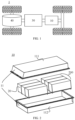
- Fig. 1 is a schematic structural diagram of a vehicle 1 according to an embodiment of the present application.
- the vehicle 1 may be a fuel vehicle, a gas vehicle or a new energy vehicle.
- the new energy vehicle may be an all-electric vehicle, a hybrid vehicle or an extended range electric vehicle, or the like.
- a motor 40, a controller 30 and a battery 10 may be provided inside the vehicle 1, and the controller 30 is configured to control the battery 10 to supply power to the motor 40.
- the battery 10 may be arranged at the bottom or the head or the tail of the vehicle 1.
- the battery 10 may be configured to supply power to the vehicle 1, for example, the battery 10 may be used as an operating power source of the vehicle 1, which is used for a circuit system of the vehicle 1, for example, for operation power requirements of the vehicle 1 during starting, navigation and running.
- the battery 10 can be used not only as an operation power supply of the vehicle 1, but also as a driving power supply of the vehicle 1, replacing or partially replacing fuel or natural gas to provide driving power for the vehicle 1.
- the battery may include a plurality of battery cells, wherein the plurality of battery cells may be in series connection, parallel connection or parallel-series connection.
- the parallel-series connection refers to a combination of series connection and parallel connection.
- the battery may also be referred to as a battery pack.
- a plurality of battery cells can be connected in series, in parallel, or in parallel-series connection to form a battery module, and then, a plurality of battery modules can be connected in series, in parallel, or in parallel-series connection to form a battery. That is, a plurality of battery cells can directly form a battery, or can first form a battery module, and then, the battery modules form a battery.
- Fig. 2 shows a schematic structural diagram of a battery 10 according to an embodiment of the present application.
- the battery 10 may include at least one battery module 200.
- the battery module 200 includes a plurality of battery cells 20.
- the battery 10 may further include a box 11, the interior of the box 11 is a hollow structure, and a plurality of battery cells 20 are accommodated in the box 11.
- Fig. 2 shows a possible implementation of the box 11 according to an embodiment of the present application.
- the box 11 may include two portions, which are referred to as a first portion 111 and a second portion 112 respectively, and the first portion 111 and the second portion 112 are snap-fitted together.
- the shapes of the first portion 111 and the second portion 112 may be determined according to a combined shape of the battery modules 200, and at least one of the first portion 111 and the second portion 112 has an opening.
- the first portion 111 and the second portion 112 may each be hollow cuboid with only one face as an opening face, the opening of the first portion 111 and the opening of the second portion 112 are disposed opposite to each other, and the first portion 111 and the second portion 112 are snap-fitted to each other to form the box 11 having a closed chamber.
- first portion 111 and the second portion 112 may be a hollow cuboid having an opening, and the other may be of a plate shape to cover the opening.
- the first portion 111 covers the opening of the second portion 112 to form the box 11 with the closed chamber which can be used for accommodating a plurality of battery cells 20. After the plurality of battery cells 20 are connected in a parallel connection or series connection or parallel-series connection manner, they are placed in the box 11 formed after the first portion 111 and the second portion 112 are snap-fitted together.
- the battery 10 may further include other structures, which will not be repeated here anymore.
- the battery 10 may also comprise a bus component.
- the bus component is configured to implement the electric connection between the plurality of battery cells 20, such as parallel connection, series connection or parallel-series connection.
- the bus component may implement the electrical connection between the battery cells 20 by connecting electrode terminals of the battery cells 20.
- the bus component may be fixed to the electrode terminals of the battery cells 20 by welding. Electric energy of the plurality of battery cells 20 may be further led out through the box 11 by an electrically conductive structure.
- the number of battery cells 20 in a battery module 200 may be set to any numerical value.
- the plurality of battery cells 20 may be connected in a parallel connection or series connection or parallel-series connection manner to achieve a larger capacity or power. Since the number of battery cells 20 included in each battery 10 may be large, in order to facilitate installation, the battery cells 20 are disposed in groups, and each group of battery cells 20 forms a battery module 200.
- the number of battery cells 20 included in the battery module 200 is not limited, and can be set as required.
- the battery 10 may include a plurality of battery modules 200, which may be connected in series, parallel or in parallel-series connection.
- the battery cells 20 provided in the embodiments of the present application may each include one or more electrode assemblies 22, which are components in the battery cell 20 that undergo electrochemical reactions.
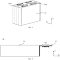
- the electrode assembly 22 may be a cylinder, a cuboid, or the like. If the electrode assembly 22 is of a cylindrical structure, the case for accommodating the electrode assembly 22 may also be of a cylindrical structure, and if the electrode assembly 22 is a cuboid structure, the case for accommodating the electrode assembly 22 may also be of a cuboid structure. As shown in Fig. 3 , each electrode assembly 22 may have a first tab 220a and a second tab 220b. The first tab 220a and the second tab 220b have opposite polarities.
- the second tab 220b is a negative tab.
- the positive tab may be formed by stacked parts of the positive electrode plate that are not coated with the positive electrode active material layer
- the negative tab may be formed by stacked parts of the negative electrode plate that are not coated with the negative electrode active material layer.
- the electrical energy generated on the electrode assembly 22 can be led out through the electrode lead.
- an electrode lead is used to connect a tab and an electrode terminal, and the electrode terminal provides electrical energy for an electrical device.
- the first tab 220a of one or more electrode assemblies 22 is connected to one electrode terminal via one electrode lead, and the second tab 220b of the one or more electrode assemblies 22 is connected to the other electrode terminal via the other electrode lead.
- the positive electrode terminal 213a is connected to the positive tab via one electrode lead
- the negative electrode terminal 213b is connected to the negative tab via the other electrode lead.
- one end of the tab lead is welded to the tab, and the other end is used to conduct electrical energy out of the battery cell.
- the first tab 220a of one or more electrode assemblies 22 is connected to one electrode lead, and the second tab 220b of the one or more electrode assemblies 22 is connected to the other electrode lead.
- one electrode assembly 22 or a plurality of electrode assemblies 22 may be provided according to the actual use requirements.
- four independent electrode assemblies 22 are provided in the battery cell 20.
- the battery cell 20 shown in Fig. 3 is only an example. In actual production, the appearance of the battery cell 20 can be changed according to different requirements.
- the embodiments of the present application provide an electrode assembly 22, as shown in Fig. 4 , which includes an electrode plate 31 and a tab 32.
- the tab 32 is arranged at an end of the electrode plate 31 in the first direction X.
- the tab 32 is provided with a bent portion 322.
- the bent portion 322 is used to provide stretching space for the tab 32.
- the electrode plate 31 is a part of the current collector coated with an active material, and may include a positive electrode plate and a negative electrode plate.
- the part of the positive electrode current collector coated with the positive electrode active material is the positive electrode plate
- the part of the negative electrode current collector coated with the negative electrode active material is the negative electrode plate.
- the positive electrode plate and the negative electrode plate may be separated by a separator so that ions in the electrolyte can pass through the separator to provide electrical energy between the positive electrode and the negative electrode, while preventing the positive electrode and the negative electrode of the battery cell from contacting and causing a short circuit.
- the region may include a positive electrode plate, a negative electrode plate, and a separator.
- the active material on the electrode plate 31 may be coated before the electrode assembly 22 is formed, or may be formed after the electrode assembly 22 is formed, for example, by a chemical reaction.
- the tab 32 is a part of the current collector that is not coated with active material, and may also be referred to as an empty foil area in the electrode assembly 22. There are usually a plurality of tabs 32 of the same polarity which are stacked together to ensure that a large current can pass without fusing.
- the tabs 32 may be arranged at an end of the electrode plate 31 in the first direction X, for example, at the end shown in Fig. 4 , and may be stacked in the second direction Y.
- the first direction X may be a height direction of the electrode assembly 22 or a width direction of the electrode assembly 22.
- the second direction Y is perpendicular to the first direction X, and may also be referred to as a thickness direction of the electrode assembly 22.
- the height direction, width direction and thickness direction of the electrode assembly are perpendicular to each other.
- the tabs 32 may be arranged at two ends of the electrode plate 31 in the first direction X. In this case, the tabs 32 at the two ends may have opposite polarities.
- two tabs 32 with opposite polarities may be arranged on two adjacent surfaces of the electrode assembly 22. That is, the tabs 32 may be arranged on the same side of the electrode assembly 22, on the adjacent sides of the electrode assembly 22, or on the opposite sides of the electrode assembly 22.
- the position of the tabs 32 is not limited in the present application.
- the tabs 32 may refer to tabs on one electrode assembly 22, or may refer to tabs of a plurality of electrode assemblies 22 that need to be overlapped together. That is, the number of the tabs 32 is not limited either in the present application.
- the bent portion 322 is a part of the tab 32 having a bent shape, and is formed by bending the tab 32.
- the bent portion 322 may have different shapes to provide stretching space for the tab 32.
- the bent portion 322 may be formed by folding at least a part of the tab 32 in the first direction X. When the electrode assembly 22 expands in the second direction Y, the tab 32 in the bent portion 322 can stretch out to avoid being pulled.
- the tab 32 in the bent portion 322 can stretch out when the electrode assembly 22 expands, providing the stretching space for the tab 32. Even when the thickness of the electrode assembly 22 expands to twice its initial state, the electrical connection of the tab 32 can still be maintained, and the tab 32 is prevented from being cracked or even broken by being pulled due to excessive expansion of the thickness of the electrode assembly 22, thereby improving the reliability of the battery.
- the overall length of the electrode assembly 22 with the bent portion 322 remains unchanged, without occupying additional space, so that the energy density of the battery cell can be ensured.
- the bent portion 322 can provide larger stretching space so as to be applicable to an electrode assembly 22 with a greater degree of expansion.
- the bent portion 322 includes at least one bent structure.
- At least a part of the bent structure is not parallel to the tab 32 in the first direction X.
- a part of the bent structure is arranged along the second direction Y, or a part of the bent structure has a certain angle with respect to the first direction X, or the bent structure is arc-shaped.
- the shape of the section of the bent portion 322 may be always the same.
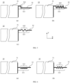
- Figs. 5 and 6 show several different bent portions 322.
- the (a) in Fig. 5 shows a schematic diagram of a bent portion 322 including a bent structure. When the electrode assembly 22 expands, a part of the bent structure arranged along the second direction Y can provide additional stretching space for the tab 32.
- the (b) and (c) in Figs. 5 show schematic diagrams of a bent portion 322 including a plurality of bent structures, where in the (b) in Fig. 5 , the bent portion 322 is formed by bent segments interconnected in the first direction X and the second direction Y, and in the (c) in Fig. 5 , the bent portion 322 is formed by a plurality of arc-shaped structures.
- the bent portion 322 in Fig. 6 is formed by bent segments interconnected along the first direction X, and there is a certain angle between adjacent bent segments. It should be understood that the shape of the bent structure is not limited in the present application.
- a plurality of tabs 32 overlap at one end of the electrode assembly 22 along the second direction Y, and the bent portion 322 can be accommodated in the space between one end and the other end of the electrode assembly 22 along the second direction Y in the second direction Y, as shown in the (a) and (b) in Figs. 5 .
- the bent portion 322 can be prevented from exceeding the edge of the electrode assembly 22 in the second direction Y and occupying additional space.
- the electrode plate 31 has a certain thickness
- the bent portion 322 can protrude from the plane in which the tabs 32 are located without exceeding the edge formed by the electrode plate 31, as shown in the (c) in Fig. 5 , which can also prevent the bent portion 322 from occupying additional space in the second direction Y.
- a plurality of tabs 32 may overlap at a middle position of the electrode assembly 22 along the second direction Y, thereby providing more accommodating space for the bent portion 322 in the second direction Y.
- the (a) in Fig. 6 shows that the bent portion 322 is accommodated in the space between the middle and one end of the electrode assembly 22 along the second direction Y
- the (b) in Fig. 6 shows that the bent portion 322 is accommodated in the space between the middle and both ends of the electrode assembly 22 along the second direction Y.
- the bent structure enables the folding of the length of the tab 32 to provide additional stretching space for the tab 32 when the electrode assembly 22 expands, so that the tab 32 is prevented from being cracked or even broken by being pulled due to excessive expansion of the thickness of the electrode assembly 22.
- the bent structure is at least one of a sawtooth shape, an arc shape, and a square wave shape.
- Figs. 5 and 6 show several possible bent structures.
- the (b) in Fig. 5 shows a case where the bent structure is a square wave shape
- the (c) in Fig. 5 shows a case where the bent structure is an arc shape
- Fig. 6 shows a case where the bent structure is a sawtooth shape.
- a bent structure may be regarded as a period of a bent portion, and a bent portion may be formed by repeating a bent structure multiple times.
- Fig. 6 shows a schematic diagram of a bent portion 322 formed by some sawtooth-shaped bent structures.
- the sawtooth-shaped bent structure may include at least two interconnected surfaces with a certain angle therebetween. At least one sawtooth-shaped bent structure may form a sawtooth-shaped bent portion 322.
- Bent structures of different shapes can provide stretching space for the tab 32, so that the tab 32 is prevented from being cracked or even broken by being pulled due to excessive expansion of the thickness of the electrode assembly 22.
- the bent portion 322 formed by the sawtooth-shaped bent structure allows more parts of the tab 32 to be folded, providing more stretching space for the tab 32. Meanwhile, even when the bent portion 322 has been formed, the length of the tab 32 in the first direction can still be adjusted by adjusting the angle between two adjacent connected surfaces in the sawtooth shape, which is beneficial for controlling the overall length of the electrode assembly 22 in the first direction X, thereby preventing the electrode assembly 22 from occupying additional space in the first direction X, and ensuring the energy density of the battery cell.
- the bent portion 322 includes a plurality of fold surfaces 323 sequentially connected along the first direction X, and the angle between two adjacent fold surfaces 323 is in the range from 30° to 120°.
- Fig. 7 is an enlarged view of this bent portion 322.
- the fold surface 323 refers to a surface on the tab 32 that is not parallel to the first direction X.
- the fold surface 323 can fold up the tab 32 in the first direction X to provide stretching space for the tab 32 when the electrode assembly 22 expands.
- the angle between two adjacent fold surfaces 323 may be an angle ⁇ as shown in the figure.
- the angle ⁇ in the bent portion 322 provided in the embodiments of the present application may be in the range from 30° to 120°. In a possible implementation, the angles between any two adjacent fold surfaces 323 are equal; and in another possible implementation, the angles ⁇ at different positions may have different values.
- the angle formed by two adjacent fold surfaces 323 will be acute, so that the component wrapping the electrode assembly 22, such as the insulating component, may easily become punctured, when the electrode assembly 22 is subjected to external impact.
- the corners of the two fold surfaces 323 may also be easily damaged and be more likely to be cracked or broken.
- the angle ⁇ is too small, the arrangement of the fold surfaces 323 will be too compact, and it will be difficult to stretch the tab 32 at the bent portion 322 when the electrode assembly 22 expands, which is not beneficial for achieving the stretching of the tab 32.
- the angle ⁇ is too large, the arrangement of the fold surfaces 323 will be too loose, and fewer parts can be folded.
- the electrode assembly 22 expands, the stretching space provided for the tab 32 is limited, making it impossible to be compatible with the significant expansion of the electrode assembly 22.
- the appropriate angle range can not only allow the stretching space required by the tab 32 when the electrode assembly 22 expands, but also cause no damage to the tab 32 and the electrode assembly 22, which is beneficial for prolonging the service life of the battery cell.
- the bent portion 322 protrudes in the second direction Y from the plane in which the tab 32 is located.
- the plane in which the tab 32 is located refers to the plane in which a plurality of tabs 32 are overlapped together and the bent portion 322 has not yet been formed.
- the plane in which the tab 32 is located may also refer to the plane in which the part of the connecting region 321 of the tab 32 other than the bent portion 322 is located.
- the bent portion 322 may protrude from one side of the plane in which the tab 32 is located, or may protrude from both sides of the plane in which the tab 32 is located.
- the folding of a part of the tab 32 can be realized to provide additional stretching space for the tab 32 when the electrode assembly 22 expands, so that the tab 32 is prevented from being cracked or even broken by being pulled due to excessive expansion of the thickness of the electrode assembly 22.
- a projection of the bent portion 322 in the first direction X has a size in the second direction Y that is in the range from 0.3 to 2 mm.
- the projection of the bent portion 322 in the first direction X is a plane perpendicular to the first direction X
- the size of the plane in the second direction Y is the size H shown in Fig. 7
- the size H has a value ranging from 0.3 to 2 mm.
- the size H may also be regarded as the distance between two points of the bent portion 322 that are farthest from each other in the second direction Y in the plane formed by the first direction X and the second direction Y.
- the size H is too small, the part of the tab 32 that is folded up will be small, and when the electrode assembly 22 expands significantly, it is impossible to provide sufficient stretching space for the tab 32. If the size H is too great, the tab 32 may be easily folded inwardly into the electrode plate 31, increasing the possibility of short circuit of the battery cell. Meanwhile, if the size H is too great, the bent portion 322 will occupy too much space in the second direction Y, which is not beneficial for improving the energy density of the battery cell.
- the appropriate size range can allow the stretching space required by the tab 32 when the electrode assembly 22 expands without taking up too much additional space, which is beneficial for improving the energy density of the battery cell.
- a plurality of tabs 32 are overlapped together to form a connecting region 321, and the bent portion 322 is arranged in the connecting region 321.
- the connecting region 321 refers to the part where the plurality of tabs 32 are overlapped together. Considering that the active material on the electrode plate 31 has a certain thickness, when the plurality of tabs 32 are overlapped together, a part of the tabs 32 close to one end of the electrode plate 31 along the first direction X needs to be folded to a certain extent. Compared with the tab 32 with more folded parts, the tab 32 not folded or with fewer folded parts will appear longer in the first direction X, and this longer part of the tab 32 is not included in the range of the connecting region 321. In addition, at the end close to the electrode plate 31 along the first direction X, the part of the tab 32 that is folded due to the thickness of the electrode plate 31 is not included in the range of the connecting region 321 either. That is, the connecting region 321 only includes the area formed by the plurality of tabs 32.
- the bent portion 322 is formed by bending the tab 32 at the connecting region 321. It can be understood that the tab 32 at the connecting region 321 includes a plurality of tabs 32 overlapped together. In the process of bending of the tab 32 at the connecting region 321, the plurality of tabs 32 can be overlapped together as a whole and the plurality of tabs 32 can be subjected to the same bending process at the same time.
- each tab can be provided with a bent portion 322, which can provide stretching space for the tab 32 when the thickness of the electrode assembly 22 expands significantly without affecting the subsequent welding of the tab lead to the tab 32, thereby ensuring the reliability of the battery during use of the battery.
- the length of the tab 32 after extension is F
- the thickness of the electrode assembly 22 in the second direction Y is E
- the distance between the end of the connecting region 321 facing away from the electrode plate 31 and the electrode plate 31 is D
- D, E and F satisfy the following relational expression: F > D 2 + E 2 .
- Fig. 8 shows a possible state of an expanded electrode assembly 22.
- the tab 32 in the bent portion 322 is stretched out from the folded state.
- the stretched tab 32 extends in the plane formed by the first direction X and the second direction Y.
- the length of the tab 32 after extension refers to the maximum length to which the tab 32 can be stretched, such as the length F shown in Fig. 8 .
- the length F of the tab 32 after extension should satisfy the relational expression (1).
- E is the thickness of the expanded electrode assembly 22 in the second direction Y.
- the thickness may be a pre-estimated value obtained by simulating the use process of the electrode assembly 22, or a value obtained by measuring the electrode assembly 22 in the same type of battery cells after the cells have been used to a certain extent.
- D is the distance between the end of the connecting region 321 facing away from the electrode plate 31 and the electrode plate 31, where the end of the connecting region 321 facing away from the electrode plate 31 will be connected to the lead of the tab 32, for example, by welding.
- the maximum length F that the tab 32 can be stretched to in the plane in which the first direction X and the second direction Y are located is calculated from the end A where the tab 32 is connected to the electrode plate 31 to the end B of the connecting region 321 facing away from the electrode plate 31.
- the end B of the connecting region 321 facing away from the electrode plate 31 may also be the end close to the electrode plate 31 in the first direction X in the area where the lead of the tab 32 is connected to the tab 32.
- the stacked thickness of an electrode assembly 22 is designed to be 7 mm, and the thickness of the electrode assembly 22 at the end of the cycle will reach 12 mm.
- the distance between the two ends of the connecting region 321 in the first direction X is 5 mm, and the length of the outermost tab 32 in the first direction X needs to be greater than 13 mm.
- the length between the two ends of the connecting region 321 in the first direction X should be greater than 5 mm, and is 6 mm in this implementation, which can meet the requirements. That is, in the case where the bent portion 322 is provided on the connecting region 321, the length between the two ends of the connecting region 321 in the first direction X can be shortened from 6 mm to 5 mm.
- a length to be folded can be reserved for the tab 32, so as to ensure the electrical connection of the tab 32 when the electrode assembly 22 expands, so that the tab 32 is prevented from being cracked or even broken by being pulled due to excessive expansion of the thickness of the electrode assembly 22.
- the electrode assembly 22 further includes an electrode lead, one end of the electrode lead being welded to an end of the connecting region 321 facing away from the electrode plate 31 in the first direction X.
- the electrode lead refers to a structure for conducting the current generated inside the electrode assembly 22 to the outside of the electrode assembly 22.
- the outer side of the electrode assembly 22 is usually wrapped with an insulating layer, and one end of the electrode lead is welded to the connecting region 321, and the other end extends out of the insulating layer to conduct current out.
- the (a) in Fig. 9 shows that when the electrode plates 31 are stacked or wound or otherwise formed into the electrode assembly 22, the tabs 32 are arranged at the end of the electrode plates 31 in the first direction X.
- a greater size of the tab 32 before being shaped along the first direction X may be reserved.
- shaping refers to the operation of overlapping a plurality of tabs 32 together.
- FIG. 9 shows the state of the electrode plate 31 after being shaped, and shows a situation where a plurality of tabs 32 are overlapped at an end of the electrode assembly 22 along the second direction Y.
- the plurality of tabs 32 are overlapped together to form a connecting region 321, where the connecting region 321 only includes an area formed by the plurality of tabs 32.
- a bent portion 322 is provided on the connecting region 321.
- the (c) in Fig. 9 shows a state where the electrode lead is welded to the end B of the connecting region 321 facing away from the electrode plate 31 in the first direction X.
- the lead of the tab 32 can be welded to at least a part of the tab 32 other than the connecting region 321 in addition to being welded to the end B of the connecting region 321, so as to ensure the welding strength between the lead of the tab 32 and the tab 32.
- FIG. 9 shows a possible state of an expanded electrode assembly 22.
- the tab 32 is pulled out from the bent portion 322 to ensure electrical connection of the tab 32. Since the possible expansion degree of the electrode assembly 22 is taken into consideration and the size of the tab 32 is designed on this basis, after the electrode assembly 22 expands, a good connection can still be maintained from the end A where the tab 32 is connected to the electrode plate 31 to the end B where the lead of the tab 32 is connected to the tab 32.
- the electrode lead can lead the current out of the inside of the electrode assembly 22, thereby realizing the function of the battery cell to provide electrical energy. Meanwhile, welding the electrode lead to the end B of the connecting region 321 can also ensure the connection strength of the tab 32 at the end B of the connecting region 321, so that the tab 32 is prevented from falling off due to the expansion of the electrode assembly 22, ensuring good electrical connection of the tab 32, and consequently improving the reliability of the battery.
- the bent portion 322 is formed by a pressing plate with a bent surface under a pressure in the range from 10 to 500 kPa.
- the pressing plate with a bent surface may be pre-processed, and when the tabs 32 are being shaped by using the pressing plate, bent portions 322 are formed on the tabs 32 along the bent surface of the pressing plate.
- a pressing plate with a bent surface may be provided on either side of the tabs 32 respectively along the second direction Y. The bent surfaces on the two pressing plates cooperate with each other. Then, after the two pressing plates simultaneously apply pressure to the tabs 32, bent portions 322 can be left on the tabs 32.
- the pressure applied by the pressing plates to the tabs 32 may be in the range from 10 kPa to 500 kPa. Too low pressure is not beneficial to the forming of the bent portion 322, and the plurality of shaped tabs 32 may easily loosen, which will also affect the subsequent production process. Excessive pressure can easily damage the tabs 32. For example, cracks may be generated in the tabs 32 during the shaping process, which may increase the internal resistance of the tabs 32 during the conduction process.
- the pressing plates with the bent surfaces can efficiently form bent portions 322 on the surfaces of the tabs 32 to provide stretching space for the tabs 32 when the electrode assembly 22 expands, so that the tabs 32 are prevented from being cracked or even broken by being pulled due to excessive expansion of the thickness of the electrode assembly 22, thereby improving the reliability of the battery. Meanwhile, forming the bent portion 322 under appropriate pressure can also improve the yield of the products, thereby improving production efficiency.
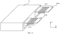
- the tabs 32 include first tabs 220a and second tabs 220b, the first tabs 220a and the second tabs 220b have opposite polarities, a plurality of first tabs 220a are overlapped together to form a first connecting region 3211, a plurality of second tabs 220b are overlapped together to form a second connecting region 3212, and the first connecting region 3211 and the second connecting region 3212 are respectively provided with a bent portion 322.
- the electrode assembly 22 is usually provided with a first tab 220a and a second tab 220b with opposite polarities.
- the first tab 220a is a positive tab 32
- the second tab 220b is a negative tab 32.
- the first connecting region 3211 of the first tab 220a and the second connecting region 3212 of the second tab 220b may both be provided with a bent portion 322, as shown in Fig. 10 .
- the first tab 220a and the second tab 220b both have a certain stretching space, that is, the first tab 220a and the second tab 220b can be stretched out from the corresponding bent portions 322 respectively to prevent the tabs 32 from being pulled and cracked or even broken.
- both tabs 32 can be protected, the electrical connection of the tabs 32 is maintained when the electrode assembly 22 expands, and the tabs 32 are prevented from being cracked or even broken by being pulled due to excessive expansion of the thickness of the electrode assembly 22, thereby improving the reliability of the battery.
- the present application further provides a battery cell including the electrode assembly 22 according to any one of the above embodiments.
- the present application further provides a battery including the battery cell 20 according to any one of the above embodiments.
- the present application further provides an electrical apparatus including the battery 10 according to any one of the above embodiments, and the battery 10 is used for providing electric energy for the electrical apparatus.
Landscapes
- Chemical & Material Sciences (AREA)
- Chemical Kinetics & Catalysis (AREA)
- Electrochemistry (AREA)
- General Chemical & Material Sciences (AREA)
- Engineering & Computer Science (AREA)
- Manufacturing & Machinery (AREA)
- Connection Of Batteries Or Terminals (AREA)
Abstract
Description
- The present application relates to the technical field of batteries, and in particular to an electrode assembly, a battery cell, a battery, and an electrical apparatus.
- Energy conservation and emission reduction are the key to the sustainable development of the automobile industry. In this case, electric vehicles have become an important part of the sustainable development of the automobile industry because of their advantages of energy saving and environmental friendliness. For the electric vehicles, the battery technology is an important factor related to their development.
- With the development of battery technology, various battery performances are constantly improving. During the use process of the battery, the reliability of the electrical performance of the battery is an important measure of the quality of the battery. Therefore, it is an urgent problem to be solved to improve the performance of a battery.
- The present application provides an electrode assembly, a battery cell, a battery, and an electrical apparatus, which can improve the reliability of the battery.
- In a first aspect, an electrode assembly is provided, including: an electrode plate; and a tab, the tab being arranged at an end of the electrode plate in a first direction, the tab being provided with a bent portion, and the bent portion being used for providing stretching space for the tab.
- In the embodiments of the present application, the tab in the bent portion can stretch out when the electrode assembly expands, providing the stretching space for the tab. Even when the thickness of the electrode assembly expands to twice its initial state, the electrical connection of the tab can still be maintained, and the tab is prevented from being cracked or even broken by being pulled due to excessive expansion of the thickness of the electrode assembly, thereby improving the reliability of the battery.
- Compared with an electrode assembly without a bent portion, the overall length of the electrode assembly with the bent portion remains unchanged, without occupying additional space, so that the energy density of the battery cell can be ensured; meanwhile, the bent portion can provide a larger stretching space so as to be applicable to an electrode assembly with a greater degree of expansion.
- In some embodiments, the bent portion includes at least one bent structure.
- The bent structure enables the folding of the length of the tab to provide additional stretching space for the tab when the electrode assembly expands, so that the tab is prevented from being cracked or even broken by being pulled due to excessive expansion of the thickness of the electrode assembly.
- In some embodiments, the bent structure is at least one of a sawtooth shape, an arc shape, and a square wave shape.
- Bent structures of different shapes can provide stretching space for the tab, so that the tab is prevented from being cracked or even broken by being pulled due to excessive expansion of the thickness of the electrode assembly. The bent portion formed by a sawtooth-shaped bent structure allows more parts of the tab to be folded, providing more stretching space for the tab. Meanwhile, even when the bent portion has been formed, the length of the tab in the first direction can still be adjusted by adjusting the angle in the sawtooth shape, which is beneficial for controlling the overall length of the electrode assembly in the first direction, thereby preventing the electrode assembly from occupying additional space in the first direction, and ensuring the energy density of the battery cell.
- In some embodiments, the bent portion includes a plurality of fold surfaces sequentially connected along the first direction, and an angle between two adjacent fold surfaces is in the range from 30° to 120°.
- The appropriate angle range can not only allow the stretching space required by the tab when the electrode assembly expands, but also cause no damage to the tab and the electrode assembly, which is beneficial for prolonging the service life of the battery cell.
- In some embodiments, the bent portion protrudes from the plane in which the tab is located in the second direction.
- In this way, the folding of a part of the tab can be realized to provide additional stretching space for the tab when the electrode assembly expands, so that the tab is prevented from being cracked or even broken by being pulled due to excessive expansion of the thickness of the electrode assembly.
- In some embodiments, a projection of the bent portion in the first direction has a size in the second direction that is in the range from 0.3 to 2 mm.
- The appropriate size range can allow the stretching space required by the tab when the electrode assembly expands without taking up too much additional space, which is beneficial for improving the energy density of the battery cell.
- In some embodiments, a plurality of the tabs are overlapped together to form a connecting region, and the bent portion is arranged in the connecting region.
- Arranging the bent portion in the connecting region can ensure that each tab can be provided with a bent portion, which can provide stretching space for the tab when the thickness of the electrode assembly expands significantly without affecting the subsequent welding of the tab lead to the tab, thereby ensuring the reliability of the battery during use of the battery.
- In some embodiments, a maximum length of the tab after extension is F, a thickness of the electrode assembly in the second direction is E, and in the first direction, a distance between the end of the connecting region facing away from the electrode plate and the electrode plate is D, and D, E and F satisfy the following relational expression:

- During the production process of the electrode assembly, depending on the designed maximum length F, a length to be folded can be reserved for the tab, so as to ensure the electrical connection of the tab when the electrode assembly expands, so that the tab is prevented from being cracked or even broken by being pulled due to excessive expansion of the thickness of the electrode assembly.
- In some embodiments, the electrode assembly further includes: an electrode lead, an end of the electrode lead being welded to the end of the connecting region facing away from the electrode plate in the first direction.
- The electrode lead can lead the current out of the inside of the electrode assembly, thereby realizing the function of the battery cell to provide electrical energy. Meanwhile, welding the electrode lead to one end of the connecting region can also ensure the connection strength of the tab at this end of the connecting region, so that the tab is prevented from falling off due to the expansion of the electrode assembly, ensuring good electrical connection of the tab, and consequently improving the reliability of the battery.
- In some embodiments, the bent portion is formed by a pressing plate with a bent surface under a pressure in the range from 10 to 500 kPa.
- The pressing plate with the bent surface can efficiently form a bent portion on the surface of the tab to provide stretching space for the tab when the electrode assembly expands, so that the tab is prevented from being cracked or even broken by being pulled due to excessive expansion of the thickness of the electrode assembly, thereby improving the reliability of the battery. Meanwhile, forming the bent portion under an appropriate pressure can also improve the yield of the products, thereby improving production efficiency.
- In some embodiments, the tabs include a first tab and a second tab, the first tab and the second tab have opposite polarities, a plurality of the first tabs are overlapped together to form a first connecting region, a plurality of the second tabs are overlapped together to form a second connecting region, and the first connecting region and the second connecting region are respectively provided with a bent portion.
- By providing bent portions on the two tabs of the electrode assembly respectively, both tabs can be protected, the electrical connection of the tabs is maintained when the electrode assembly expands, and the tabs are prevented from being cracked or even broken by being pulled due to excessive expansion of the thickness of the electrode assembly, thereby improving the reliability of the battery.
- In a second aspect, a battery cell is provided, including the electrode assembly of any one of the above embodiments.
- In a third aspect, a battery is provided, including the battery cell of any one of the above embodiments.
- In a fourth aspect, an electrical apparatus is provided, including the battery of any one of the above embodiments, and the battery is used for providing electric energy for the electrical apparatus.
- In order to more clearly illustrate the technical solutions of the embodiments of the present application, the drawings to be used in the embodiments of the present application will be described briefly below. Obviously, the drawings described below depict merely some embodiments of the present application. For those skilled in the art, other drawings can also be obtained based on these drawings without any creative effort.
-
Fig. 1 is a schematic structural diagram of a vehicle provided in an embodiment of the present application; -
Fig. 2 is a schematic exploded structural diagram of a battery provided in an embodiment of the present application; -
Fig. 3 is a schematic exploded structural diagram of a battery cell provided in an embodiment of the present application; -
Fig. 4 is a schematic structural diagram of an electrode assembly provided in an embodiment of the present application; -
Fig. 5 is a schematic structural diagram of a bent portion in some electrode assemblies provided in an embodiment of the present application; -
Fig. 6 is a schematic structural diagram of a bent portion in some other electrode assemblies provided in an embodiment of the present application; -
Fig. 7 is a schematic structural diagram of a bent portion provided in an embodiment of the present application; -
Fig. 8 is a schematic structural diagram of an expanded electrode assembly provided in an embodiment of the present application; -
Fig. 9 is a schematic structural diagram of an electrode assembly at different stages provided in an embodiment of the present application; and -
Fig. 10 is a schematic structural diagram of another electrode assembly provided in an embodiment of the present application. - In the drawings, the figures are not drawn to the actual scale.
- Implementations of the present application are described in further detail below in conjunction with the drawings and embodiments. The following detailed description of the embodiments and the drawings are configured to illustrate the principles of the present application by way of example, but should not be configured to limit the scope of the present application, that is, the present application is not limited to the described embodiments.
- In the description of the present application, it should be noted that, unless otherwise stated, "plurality of" means two or more; the orientation or positional relationships indicated by the terms "upper", "lower", "left", "right", "inner" and "outer" are only for facilitating the description of the present application and simplifying the description, rather than indicating or implying that the apparatus or element referred to must have a particular orientation or be constructed and operated in a particular orientation, and therefore will not be interpreted as limiting the present application. In addition, the terms "first", "second" and "third" are used for descriptive purposes only, and cannot be construed as indicating or implying relative importance. "Perpendicular" is not strictly perpendicular, but within the allowable range of errors. "Parallel" is not strictly parallel, but within the allowable range of errors. All technical and scientific terms used in the present application have the same meanings as those commonly understood by those skilled in the art to which the present application belongs. The terms used in the application specification of the present application are merely for the purpose of describing specific embodiments, but are not intended to limit the present application. The terms "comprising" and "having" and any variations thereof in the specification and the claims of the present application as well as the foregoing description of the drawings are intended to cover non-exclusive inclusions.
- Orientation words appearing in the following description are all directions shown in the drawings, and do not limit the specific structure of the present application. In the description of the present application, it should also be noted that, unless otherwise expressly specified and limited, the terms "mount," "connected," and "connecting" should be broadly understood, for example, they may be a fixed connection or a detachable connection or be an integrated connection; or may be a direct connection or an indirect connection through an intermediate medium. For those of ordinary skills in the art, the specific meanings of the above terms in the present application may be understood according to specific circumstances.
- The reference to "embodiment" in the present application means that specific features, structures or characteristics described with reference to embodiments may be included in at least one embodiment of the present application. The appearance of this phrase in various places in the specification does not necessarily refer to the same embodiment, nor is it a separate or alternative embodiment that is mutually exclusive with other embodiments. It is understood explicitly and implicitly by those skilled in the art that the embodiments described in the present application can be combined with other embodiments.
- In the present application, the term "and/or" is only an association relationship for describing associated objects, indicating that there may be three relationships, for example, the expression A and/or B may represent three situations: A exists alone, both A and B exist, and B exists alone. In addition, the character "/" in the present application generally means that the associated objects before and after it are in an "or" relationship.
- In the present application, "a plurality of" means two or more (including two), similarly, "a plurality of groups" means two or more groups (including two groups), and "a plurality of sheets" means two or more sheets (including two sheets).
- In the embodiments of the present application, the same reference numerals indicate the same components and, for the sake of brevity, the detailed description of the same components is omitted in the different embodiments. It should be understood that the thickness, length, width and other dimensions of the various components in the embodiments of the present application shown in the drawings, as well as the overall thickness, length, width and other dimensions of an integrated apparatus, are for illustrative purposes only, and should not constitute any limitation to the present application.
- In the present application, the battery cell may include a lithium-ion secondary battery, a lithium-ion primary battery, a lithium sulfur battery, a sodium/lithium-ion battery, a sodium-ion battery, a lithium metal battery or a magnesium-ion battery and so on. This is not limited in the embodiments of the present application. The battery cell may be in a cylindrical shape, a flat shape, a cuboid shape or another shape, which is not limited in the embodiments of the present application either. The battery cells are generally classified into three types depending on the way of package: cylindrical battery cells, prismatic battery cells and pouch battery cells, which are also not limited in the embodiments of the present application.
- The battery mentioned in the embodiments of the present application refers to a single physical module including one or more battery cells to provide a higher voltage and capacity. For example, the battery mentioned in the present application may include a battery module or a battery pack, etc. The battery generally includes a box for packaging one or more battery cells. The box can prevent liquid or other foreign matters from affecting charging or discharging of the battery cells.
- The battery cell includes an electrode assembly and an electrolyte solution, the electrode assembly being composed of a positive electrode plate, a negative electrode plate and a separator. The battery cell operates mainly relying on the movement of metal ions between the positive electrode plate and the negative electrode plate. The positive electrode plate includes a positive electrode current collector and a positive electrode active material layer. The positive electrode active material layer is coated on the surface of the positive electrode current collector. The parts of the positive electrode current collector not coated with the positive electrode active material layer protrude from the parts of the positive electrode current collector coated with the positive electrode active material layer, and the parts of the positive electrode current collector not coated with the positive electrode active material layer serve as a positive tab. Taking a lithium-ion battery as an example, the material of the positive electrode current collector may be aluminum, and the positive electrode active material may be lithium cobalt oxide, lithium iron phosphate, ternary lithium, lithium manganate, etc. The negative electrode plate includes a negative electrode current collector and a negative electrode active material layer. The negative electrode active material layer is coated on the surface of the negative electrode current collector. The parts of the negative electrode current collector not coated with the negative electrode active material layer protrudes from the parts of the negative electrode current collector coated with the negative electrode active material layer, and the parts of the negative electrode current collector not coated with the negative electrode active material layer serve as a negative tab. The material of the negative electrode current collector may be copper, and the negative electrode active material may be carbon, silicon, lithium metal or lithium alloy, etc. In order to ensure that no fusing occurs when a large current passes, there are a plurality of positive tabs which are stacked together, and there are a plurality of negative tabs which are stacked together. The separator may be polypropylene (PP), polyethylene (PE), etc. In addition, the electrode assembly may have a wound structure or a laminated structure, but the embodiments of the present application are not limited thereto.
- In order to meet different power requirements, the battery may include a plurality of battery cells. The plurality of battery cells may be connected in series, in parallel, or in parallel-series connection. The parallel-series connection refers to a combination of series connection and parallel connection. Optionally, first, a plurality of battery cells can be connected in series, in parallel, or in parallel-series connection to form a battery module, and then, a plurality of battery modules can be connected in series, in parallel, or in parallel-series connection to form a battery. That is, a plurality of battery cells can directly form a battery, or can first form a battery module, and then, the battery modules form a battery. The battery is further arranged in the electrical device to provide electrical energy for the electrical device.
- In the battery cell in the battery, chemical energy is converted into electrical energy through its internal chemical reactions, and the electrical energy is conducted out via the tabs of the electrode assembly in order to supply power to an external electrical device. During the charging and discharging process, the electrode assembly in the battery cell is prone to expansion. Especially when using materials with high energy density, such as silicon and lithium metal, as the negative electrode, the volumetric expansion of the electrode assembly will be greater. Experiments have shown that the thickness of the expanded electrode assembly can reach 200% of its initial thickness. However, when producing an electrode assembly, the plurality of tabs overlapped together will be pulled due to the expansion of the electrode assembly. When the electrode assembly expands to a great extent, the tabs are very likely to be cracked or even broken, resulting in an increase in the internal resistance of the battery cell and producing electrical heating, which may further cause a decrease in the capacity of the battery cell, thereby reducing the reliability of the battery during use.
- In view of this, the present application provides an electrode assembly, in which by providing a bent portion on the tab, when the electrode assembly expands, the tab can be stretched out from the bent portion to maintain the electrical connection of the tab, so that the tab is prevented from being cracked or even broken by being pulled due to excessive expansion of the thickness of the electrode assembly, thereby improving the reliability of the battery.
- The technical solutions described in the embodiments of the present application are all applicable to various electrical devices using batteries. The electrical device may be, but not limited to, a vehicle, a mobile phone, a portable device, a laptop, a ship, a spacecraft, an electric toy, an electric tool, and so on. The vehicle may be a fuel vehicle, a gas vehicle or a new energy vehicle. The new energy vehicle may be an all-electric vehicle, a hybrid electric vehicle, an extended range electric vehicle, or the like. The spacecraft includes airplanes, rockets, space shuttles, spaceships, and the like. The electric toy includes fixed or mobile electric toys, such as game consoles, electric car toys, electric ship toys and electric aircraft toys. The electric tool includes metal cutting electric tools, grinding electric tools, assembly electric tools and railway electric tools, such as electric drills, electric grinders, electric wrenches, electric screwdrivers, electric hammers, impact drills, concrete vibrators and electric planers. The electrical device is not specially limited in the embodiments of the present application.
- For ease of description, in the following embodiments, the electrical device is, for example, a vehicle.
- For example,
Fig. 1 is a schematic structural diagram of avehicle 1 according to an embodiment of the present application. Thevehicle 1 may be a fuel vehicle, a gas vehicle or a new energy vehicle. The new energy vehicle may be an all-electric vehicle, a hybrid vehicle or an extended range electric vehicle, or the like. Amotor 40, acontroller 30 and abattery 10 may be provided inside thevehicle 1, and thecontroller 30 is configured to control thebattery 10 to supply power to themotor 40. For example, thebattery 10 may be arranged at the bottom or the head or the tail of thevehicle 1. Thebattery 10 may be configured to supply power to thevehicle 1, for example, thebattery 10 may be used as an operating power source of thevehicle 1, which is used for a circuit system of thevehicle 1, for example, for operation power requirements of thevehicle 1 during starting, navigation and running. In another embodiment of the present application, thebattery 10 can be used not only as an operation power supply of thevehicle 1, but also as a driving power supply of thevehicle 1, replacing or partially replacing fuel or natural gas to provide driving power for thevehicle 1. - In order to meet different power requirements, the battery may include a plurality of battery cells, wherein the plurality of battery cells may be in series connection, parallel connection or parallel-series connection. The parallel-series connection refers to a combination of series connection and parallel connection. The battery may also be referred to as a battery pack. Optionally, first, a plurality of battery cells can be connected in series, in parallel, or in parallel-series connection to form a battery module, and then, a plurality of battery modules can be connected in series, in parallel, or in parallel-series connection to form a battery. That is, a plurality of battery cells can directly form a battery, or can first form a battery module, and then, the battery modules form a battery.
- For example,
Fig. 2 shows a schematic structural diagram of abattery 10 according to an embodiment of the present application. Thebattery 10 may include at least onebattery module 200. Thebattery module 200 includes a plurality ofbattery cells 20. Thebattery 10 may further include abox 11, the interior of thebox 11 is a hollow structure, and a plurality ofbattery cells 20 are accommodated in thebox 11.Fig. 2 shows a possible implementation of thebox 11 according to an embodiment of the present application. As shown inFig. 2 , thebox 11 may include two portions, which are referred to as afirst portion 111 and asecond portion 112 respectively, and thefirst portion 111 and thesecond portion 112 are snap-fitted together. The shapes of thefirst portion 111 and thesecond portion 112 may be determined according to a combined shape of thebattery modules 200, and at least one of thefirst portion 111 and thesecond portion 112 has an opening. For example, as shown inFig. 2 , thefirst portion 111 and thesecond portion 112 may each be hollow cuboid with only one face as an opening face, the opening of thefirst portion 111 and the opening of thesecond portion 112 are disposed opposite to each other, and thefirst portion 111 and thesecond portion 112 are snap-fitted to each other to form thebox 11 having a closed chamber. - For another example, unlike that shown in
Fig. 2 , only one of thefirst portion 111 and thesecond portion 112 may be a hollow cuboid having an opening, and the other may be of a plate shape to cover the opening. For example, here taking thesecond portion 112 as a hollow cuboid with only one face as an opening face and thefirst portion 111 of a plate shape as an example, thefirst portion 111 covers the opening of thesecond portion 112 to form thebox 11 with the closed chamber which can be used for accommodating a plurality ofbattery cells 20. After the plurality ofbattery cells 20 are connected in a parallel connection or series connection or parallel-series connection manner, they are placed in thebox 11 formed after thefirst portion 111 and thesecond portion 112 are snap-fitted together. - Optionally, the
battery 10 may further include other structures, which will not be repeated here anymore. For example, thebattery 10 may also comprise a bus component. The bus component is configured to implement the electric connection between the plurality ofbattery cells 20, such as parallel connection, series connection or parallel-series connection. Specifically, the bus component may implement the electrical connection between thebattery cells 20 by connecting electrode terminals of thebattery cells 20. Further, the bus component may be fixed to the electrode terminals of thebattery cells 20 by welding. Electric energy of the plurality ofbattery cells 20 may be further led out through thebox 11 by an electrically conductive structure. - Depending on different power requirements, the number of
battery cells 20 in abattery module 200 may be set to any numerical value. The plurality ofbattery cells 20 may be connected in a parallel connection or series connection or parallel-series connection manner to achieve a larger capacity or power. Since the number ofbattery cells 20 included in eachbattery 10 may be large, in order to facilitate installation, thebattery cells 20 are disposed in groups, and each group ofbattery cells 20 forms abattery module 200. The number ofbattery cells 20 included in thebattery module 200 is not limited, and can be set as required. - The
battery 10 may include a plurality ofbattery modules 200, which may be connected in series, parallel or in parallel-series connection. - The
battery cells 20 provided in the embodiments of the present application may each include one ormore electrode assemblies 22, which are components in thebattery cell 20 that undergo electrochemical reactions. Theelectrode assembly 22 may be a cylinder, a cuboid, or the like. If theelectrode assembly 22 is of a cylindrical structure, the case for accommodating theelectrode assembly 22 may also be of a cylindrical structure, and if theelectrode assembly 22 is a cuboid structure, the case for accommodating theelectrode assembly 22 may also be of a cuboid structure. As shown inFig. 3 , eachelectrode assembly 22 may have afirst tab 220a and asecond tab 220b. Thefirst tab 220a and thesecond tab 220b have opposite polarities. For example, when thefirst tab 220a is a positive tab, thesecond tab 220b is a negative tab. The positive tab may be formed by stacked parts of the positive electrode plate that are not coated with the positive electrode active material layer, and the negative tab may be formed by stacked parts of the negative electrode plate that are not coated with the negative electrode active material layer. - The electrical energy generated on the
electrode assembly 22 can be led out through the electrode lead. In one type of battery cell, such as a hard-shell battery cell, an electrode lead is used to connect a tab and an electrode terminal, and the electrode terminal provides electrical energy for an electrical device. Thefirst tab 220a of one ormore electrode assemblies 22 is connected to one electrode terminal via one electrode lead, and thesecond tab 220b of the one ormore electrode assemblies 22 is connected to the other electrode terminal via the other electrode lead. For example, the positive electrode terminal 213a is connected to the positive tab via one electrode lead, and the negative electrode terminal 213b is connected to the negative tab via the other electrode lead. In another type of battery cell, such as a pouch battery cell, one end of the tab lead is welded to the tab, and the other end is used to conduct electrical energy out of the battery cell. Thefirst tab 220a of one ormore electrode assemblies 22 is connected to one electrode lead, and thesecond tab 220b of the one ormore electrode assemblies 22 is connected to the other electrode lead. - In the
battery cell 20, oneelectrode assembly 22 or a plurality ofelectrode assemblies 22 may be provided according to the actual use requirements. For example, as shown inFig. 3 , fourindependent electrode assemblies 22 are provided in thebattery cell 20. Thebattery cell 20 shown inFig. 3 is only an example. In actual production, the appearance of thebattery cell 20 can be changed according to different requirements. - The embodiments of the present application provide an
electrode assembly 22, as shown inFig. 4 , which includes anelectrode plate 31 and atab 32. Thetab 32 is arranged at an end of theelectrode plate 31 in the first direction X. Thetab 32 is provided with abent portion 322. Thebent portion 322 is used to provide stretching space for thetab 32. - The
electrode plate 31 is a part of the current collector coated with an active material, and may include a positive electrode plate and a negative electrode plate. The part of the positive electrode current collector coated with the positive electrode active material is the positive electrode plate, and the part of the negative electrode current collector coated with the negative electrode active material is the negative electrode plate. The positive electrode plate and the negative electrode plate may be separated by a separator so that ions in the electrolyte can pass through the separator to provide electrical energy between the positive electrode and the negative electrode, while preventing the positive electrode and the negative electrode of the battery cell from contacting and causing a short circuit. Theelectrode plate 31 inFig. 4 shows a region formed by a plurality ofelectrode plates 31, and the region may include a positive electrode plate, a negative electrode plate, and a separator. The active material on theelectrode plate 31 may be coated before theelectrode assembly 22 is formed, or may be formed after theelectrode assembly 22 is formed, for example, by a chemical reaction. - The
tab 32 is a part of the current collector that is not coated with active material, and may also be referred to as an empty foil area in theelectrode assembly 22. There are usually a plurality oftabs 32 of the same polarity which are stacked together to ensure that a large current can pass without fusing. Thetabs 32 may be arranged at an end of theelectrode plate 31 in the first direction X, for example, at the end shown inFig. 4 , and may be stacked in the second direction Y. The first direction X may be a height direction of theelectrode assembly 22 or a width direction of theelectrode assembly 22. The second direction Y is perpendicular to the first direction X, and may also be referred to as a thickness direction of theelectrode assembly 22. Among them, the height direction, width direction and thickness direction of the electrode assembly are perpendicular to each other. In a possible implementation, thetabs 32 may be arranged at two ends of theelectrode plate 31 in the first direction X. In this case, thetabs 32 at the two ends may have opposite polarities. In another possible implementation, twotabs 32 with opposite polarities may be arranged on two adjacent surfaces of theelectrode assembly 22. That is, thetabs 32 may be arranged on the same side of theelectrode assembly 22, on the adjacent sides of theelectrode assembly 22, or on the opposite sides of theelectrode assembly 22. The position of thetabs 32 is not limited in the present application. Thetabs 32 may refer to tabs on oneelectrode assembly 22, or may refer to tabs of a plurality ofelectrode assemblies 22 that need to be overlapped together. That is, the number of thetabs 32 is not limited either in the present application. - The
bent portion 322 is a part of thetab 32 having a bent shape, and is formed by bending thetab 32. Thebent portion 322 may have different shapes to provide stretching space for thetab 32. As can be seen fromFig. 4 , thebent portion 322 may be formed by folding at least a part of thetab 32 in the first direction X. When theelectrode assembly 22 expands in the second direction Y, thetab 32 in thebent portion 322 can stretch out to avoid being pulled. - In the embodiments of the present application, the
tab 32 in thebent portion 322 can stretch out when theelectrode assembly 22 expands, providing the stretching space for thetab 32. Even when the thickness of theelectrode assembly 22 expands to twice its initial state, the electrical connection of thetab 32 can still be maintained, and thetab 32 is prevented from being cracked or even broken by being pulled due to excessive expansion of the thickness of theelectrode assembly 22, thereby improving the reliability of the battery. - Compared with an
electrode assembly 22 without abent portion 322, the overall length of theelectrode assembly 22 with thebent portion 322 remains unchanged, without occupying additional space, so that the energy density of the battery cell can be ensured. Meanwhile, thebent portion 322 can provide larger stretching space so as to be applicable to anelectrode assembly 22 with a greater degree of expansion. - According to some embodiments of the present application, optionally, the
bent portion 322 includes at least one bent structure. - At least a part of the bent structure is not parallel to the
tab 32 in the first direction X. For example, a part of the bent structure is arranged along the second direction Y, or a part of the bent structure has a certain angle with respect to the first direction X, or the bent structure is arc-shaped. In a plane formed by the first direction X and the second direction Y, the shape of the section of thebent portion 322 may be always the same. -
Figs. 5 and 6 show several differentbent portions 322. The (a) inFig. 5 shows a schematic diagram of abent portion 322 including a bent structure. When theelectrode assembly 22 expands, a part of the bent structure arranged along the second direction Y can provide additional stretching space for thetab 32. The (b) and (c) inFigs. 5 show schematic diagrams of abent portion 322 including a plurality of bent structures, where in the (b) inFig. 5 , thebent portion 322 is formed by bent segments interconnected in the first direction X and the second direction Y, and in the (c) inFig. 5 , thebent portion 322 is formed by a plurality of arc-shaped structures. Thebent portion 322 inFig. 6 is formed by bent segments interconnected along the first direction X, and there is a certain angle between adjacent bent segments. It should be understood that the shape of the bent structure is not limited in the present application. - In the
electrode assembly 22 shown inFig. 5 , a plurality oftabs 32 overlap at one end of theelectrode assembly 22 along the second direction Y, and thebent portion 322 can be accommodated in the space between one end and the other end of theelectrode assembly 22 along the second direction Y in the second direction Y, as shown in the (a) and (b) inFigs. 5 . In this way, thebent portion 322 can be prevented from exceeding the edge of theelectrode assembly 22 in the second direction Y and occupying additional space. In a possible implementation, considering that theelectrode plate 31 has a certain thickness, there is a certain space between the plurality oftabs 32 overlapped together and the edge of theelectrode plate 31 in the second direction Y. Therefore, thebent portion 322 can protrude from the plane in which thetabs 32 are located without exceeding the edge formed by theelectrode plate 31, as shown in the (c) inFig. 5 , which can also prevent thebent portion 322 from occupying additional space in the second direction Y. Optionally, in theelectrode assembly 22 shown inFig. 6 , a plurality oftabs 32 may overlap at a middle position of theelectrode assembly 22 along the second direction Y, thereby providing more accommodating space for thebent portion 322 in the second direction Y. For example, the (a) inFig. 6 shows that thebent portion 322 is accommodated in the space between the middle and one end of theelectrode assembly 22 along the second direction Y, and the (b) inFig. 6 shows that thebent portion 322 is accommodated in the space between the middle and both ends of theelectrode assembly 22 along the second direction Y. - The bent structure enables the folding of the length of the
tab 32 to provide additional stretching space for thetab 32 when theelectrode assembly 22 expands, so that thetab 32 is prevented from being cracked or even broken by being pulled due to excessive expansion of the thickness of theelectrode assembly 22. - According to some embodiments of the present application, optionally, the bent structure is at least one of a sawtooth shape, an arc shape, and a square wave shape.
-
Figs. 5 and 6 show several possible bent structures. The (b) inFig. 5 shows a case where the bent structure is a square wave shape, the (c) inFig. 5 shows a case where the bent structure is an arc shape, andFig. 6 shows a case where the bent structure is a sawtooth shape. A bent structure may be regarded as a period of a bent portion, and a bent portion may be formed by repeating a bent structure multiple times. -
Fig. 6 shows a schematic diagram of abent portion 322 formed by some sawtooth-shaped bent structures. The sawtooth-shaped bent structure may include at least two interconnected surfaces with a certain angle therebetween. At least one sawtooth-shaped bent structure may form a sawtooth-shapedbent portion 322. - Bent structures of different shapes can provide stretching space for the
tab 32, so that thetab 32 is prevented from being cracked or even broken by being pulled due to excessive expansion of the thickness of theelectrode assembly 22. Thebent portion 322 formed by the sawtooth-shaped bent structure allows more parts of thetab 32 to be folded, providing more stretching space for thetab 32. Meanwhile, even when thebent portion 322 has been formed, the length of thetab 32 in the first direction can still be adjusted by adjusting the angle between two adjacent connected surfaces in the sawtooth shape, which is beneficial for controlling the overall length of theelectrode assembly 22 in the first direction X, thereby preventing theelectrode assembly 22 from occupying additional space in the first direction X, and ensuring the energy density of the battery cell. - According to some embodiments of the present application, optionally, the
bent portion 322 includes a plurality of fold surfaces 323 sequentially connected along the first direction X, and the angle between two adjacent fold surfaces 323 is in the range from 30° to 120°. - Taking the
bent portion 322 shown in the (b) inFig. 6 as an example,Fig. 7 is an enlarged view of thisbent portion 322. Thefold surface 323 refers to a surface on thetab 32 that is not parallel to the first direction X. Thefold surface 323 can fold up thetab 32 in the first direction X to provide stretching space for thetab 32 when theelectrode assembly 22 expands. The angle between two adjacent fold surfaces 323 may be an angle α as shown in the figure. The angle α in thebent portion 322 provided in the embodiments of the present application may be in the range from 30° to 120°. In a possible implementation, the angles between any two adjacent fold surfaces 323 are equal; and in another possible implementation, the angles α at different positions may have different values. - If the angle α is too small, the angle formed by two adjacent fold surfaces 323 will be acute, so that the component wrapping the
electrode assembly 22, such as the insulating component, may easily become punctured, when theelectrode assembly 22 is subjected to external impact. The corners of the twofold surfaces 323 may also be easily damaged and be more likely to be cracked or broken. Meanwhile, if the angle α is too small, the arrangement of the fold surfaces 323 will be too compact, and it will be difficult to stretch thetab 32 at thebent portion 322 when theelectrode assembly 22 expands, which is not beneficial for achieving the stretching of thetab 32. - If the angle α is too large, the arrangement of the fold surfaces 323 will be too loose, and fewer parts can be folded. When the
electrode assembly 22 expands, the stretching space provided for thetab 32 is limited, making it impossible to be compatible with the significant expansion of theelectrode assembly 22. - The appropriate angle range can not only allow the stretching space required by the
tab 32 when theelectrode assembly 22 expands, but also cause no damage to thetab 32 and theelectrode assembly 22, which is beneficial for prolonging the service life of the battery cell. - According to some embodiments of the present application, optionally, the
bent portion 322 protrudes in the second direction Y from the plane in which thetab 32 is located. - The plane in which the
tab 32 is located refers to the plane in which a plurality oftabs 32 are overlapped together and thebent portion 322 has not yet been formed. In other words, the plane in which thetab 32 is located may also refer to the plane in which the part of the connectingregion 321 of thetab 32 other than thebent portion 322 is located. As shown inFigs. 4 to 7 , in the second direction Y, thebent portion 322 may protrude from one side of the plane in which thetab 32 is located, or may protrude from both sides of the plane in which thetab 32 is located. - In this way, the folding of a part of the
tab 32 can be realized to provide additional stretching space for thetab 32 when theelectrode assembly 22 expands, so that thetab 32 is prevented from being cracked or even broken by being pulled due to excessive expansion of the thickness of theelectrode assembly 22. - According to some embodiments of the present application, optionally, a projection of the
bent portion 322 in the first direction X has a size in the second direction Y that is in the range from 0.3 to 2 mm. - As shown in
Fig. 7 , the projection of thebent portion 322 in the first direction X is a plane perpendicular to the first direction X, and the size of the plane in the second direction Y is the size H shown inFig. 7 , and the size H has a value ranging from 0.3 to 2 mm. The size H may also be regarded as the distance between two points of thebent portion 322 that are farthest from each other in the second direction Y in the plane formed by the first direction X and the second direction Y. - If the size H is too small, the part of the
tab 32 that is folded up will be small, and when theelectrode assembly 22 expands significantly, it is impossible to provide sufficient stretching space for thetab 32. If the size H is too great, thetab 32 may be easily folded inwardly into theelectrode plate 31, increasing the possibility of short circuit of the battery cell. Meanwhile, if the size H is too great, thebent portion 322 will occupy too much space in the second direction Y, which is not beneficial for improving the energy density of the battery cell. - The appropriate size range can allow the stretching space required by the
tab 32 when theelectrode assembly 22 expands without taking up too much additional space, which is beneficial for improving the energy density of the battery cell. - According to some embodiments of the present application, optionally, a plurality of
tabs 32 are overlapped together to form a connectingregion 321, and thebent portion 322 is arranged in the connectingregion 321. - The connecting
region 321 refers to the part where the plurality oftabs 32 are overlapped together. Considering that the active material on theelectrode plate 31 has a certain thickness, when the plurality oftabs 32 are overlapped together, a part of thetabs 32 close to one end of theelectrode plate 31 along the first direction X needs to be folded to a certain extent. Compared with thetab 32 with more folded parts, thetab 32 not folded or with fewer folded parts will appear longer in the first direction X, and this longer part of thetab 32 is not included in the range of the connectingregion 321. In addition, at the end close to theelectrode plate 31 along the first direction X, the part of thetab 32 that is folded due to the thickness of theelectrode plate 31 is not included in the range of the connectingregion 321 either. That is, the connectingregion 321 only includes the area formed by the plurality oftabs 32. - The
bent portion 322 is formed by bending thetab 32 at the connectingregion 321. It can be understood that thetab 32 at the connectingregion 321 includes a plurality oftabs 32 overlapped together. In the process of bending of thetab 32 at the connectingregion 321, the plurality oftabs 32 can be overlapped together as a whole and the plurality oftabs 32 can be subjected to the same bending process at the same time. - By providing the
bent portion 322 in the connectingregion 321, it can be ensured that each tab can be provided with abent portion 322, which can provide stretching space for thetab 32 when the thickness of theelectrode assembly 22 expands significantly without affecting the subsequent welding of the tab lead to thetab 32, thereby ensuring the reliability of the battery during use of the battery. - According to some embodiments of the present application, optionally, the length of the
tab 32 after extension is F, the thickness of theelectrode assembly 22 in the second direction Y is E, and in the first direction X, the distance between the end of the connectingregion 321 facing away from theelectrode plate 31 and theelectrode plate 31 is D, and D, E and F satisfy the following relational expression:
-
Fig. 8 shows a possible state of an expandedelectrode assembly 22. As shown inFig. 8 , after theelectrode assembly 22 expands, thetab 32 in thebent portion 322 is stretched out from the folded state. The stretchedtab 32 extends in the plane formed by the first direction X and the second direction Y. When thetab 32 is stretched to the maximum length, it may appear as an oblique line in the plane formed by the first direction X and the second direction Y. The length of thetab 32 after extension refers to the maximum length to which thetab 32 can be stretched, such as the length F shown inFig. 8 . In order to ensure the electrical connection of thetab 32, the length F of thetab 32 after extension should satisfy the relational expression (1).
- E is the thickness of the expanded
electrode assembly 22 in the second direction Y. The thickness may be a pre-estimated value obtained by simulating the use process of theelectrode assembly 22, or a value obtained by measuring theelectrode assembly 22 in the same type of battery cells after the cells have been used to a certain extent. D is the distance between the end of the connectingregion 321 facing away from theelectrode plate 31 and theelectrode plate 31, where the end of the connectingregion 321 facing away from theelectrode plate 31 will be connected to the lead of thetab 32, for example, by welding. Therefore, the maximum length F that thetab 32 can be stretched to in the plane in which the first direction X and the second direction Y are located is calculated from the end A where thetab 32 is connected to theelectrode plate 31 to the end B of the connectingregion 321 facing away from theelectrode plate 31. In a possible calculation method, the end B of the connectingregion 321 facing away from theelectrode plate 31 may also be the end close to theelectrode plate 31 in the first direction X in the area where the lead of thetab 32 is connected to thetab 32. - In a specific implementation, taking a
stacked electrode assembly 22 as an example, the stacked thickness of anelectrode assembly 22 is designed to be 7 mm, and the thickness of theelectrode assembly 22 at the end of the cycle will reach 12 mm. The distance between the two ends of the connectingregion 321 in the first direction X is 5 mm, and the length of theoutermost tab 32 in the first direction X needs to be greater than 13 mm. In addition, since the distance between the two ends of the connectingregion 321 is designed to be 5 mm, in the state where thebent portion 322 has not yet been formed in the connectingregion 321, the length between the two ends of the connectingregion 321 in the first direction X should be greater than 5 mm, and is 6 mm in this implementation, which can meet the requirements. That is, in the case where thebent portion 322 is provided on the connectingregion 321, the length between the two ends of the connectingregion 321 in the first direction X can be shortened from 6 mm to 5 mm. - During the production process of the
electrode assembly 22, depending on the designed maximum length F, a length to be folded can be reserved for thetab 32, so as to ensure the electrical connection of thetab 32 when theelectrode assembly 22 expands, so that thetab 32 is prevented from being cracked or even broken by being pulled due to excessive expansion of the thickness of theelectrode assembly 22. - According to some embodiments of the present application, optionally, the
electrode assembly 22 further includes an electrode lead, one end of the electrode lead being welded to an end of the connectingregion 321 facing away from theelectrode plate 31 in the first direction X. - The electrode lead refers to a structure for conducting the current generated inside the
electrode assembly 22 to the outside of theelectrode assembly 22. In order to avoid short circuit caused by electrical connection between theelectrode assembly 22 and other parts of the battery cell, the outer side of theelectrode assembly 22 is usually wrapped with an insulating layer, and one end of the electrode lead is welded to the connectingregion 321, and the other end extends out of the insulating layer to conduct current out. - Possible states of the
electrode assembly 22 provided in the embodiments of the present application at different stages are to be described below in conjunction withFig. 9 . - The (a) in
Fig. 9 shows that when theelectrode plates 31 are stacked or wound or otherwise formed into theelectrode assembly 22, thetabs 32 are arranged at the end of theelectrode plates 31 in the first direction X. During the production process of theelectrode assembly 22, considering the part of thetab 32 in thebent portion 322 that needs to be folded, a greater size of thetab 32 before being shaped along the first direction X may be reserved. Here, shaping refers to the operation of overlapping a plurality oftabs 32 together. - The (b) in
Fig. 9 shows the state of theelectrode plate 31 after being shaped, and shows a situation where a plurality oftabs 32 are overlapped at an end of theelectrode assembly 22 along the second direction Y. The plurality oftabs 32 are overlapped together to form a connectingregion 321, where the connectingregion 321 only includes an area formed by the plurality oftabs 32. In the embodiments of the present application, while thetabs 32 are being shaped, abent portion 322 is provided on the connectingregion 321. - The (c) in
Fig. 9 shows a state where the electrode lead is welded to the end B of the connectingregion 321 facing away from theelectrode plate 31 in the first direction X. There is a certain overlap between the electrode lead and the welded part of the connectingregion 321, which can ensure that each layer oftab 32 can conduct the electrons inside theelectrode assembly 22 to the outside through the lead of thetab 32, thereby forming a stable current. In a possible implementation, the lead of thetab 32 can be welded to at least a part of thetab 32 other than the connectingregion 321 in addition to being welded to the end B of the connectingregion 321, so as to ensure the welding strength between the lead of thetab 32 and thetab 32. - The (d) in
Fig. 9 shows a possible state of an expandedelectrode assembly 22. After theelectrode assembly 22 expands, thetab 32 is pulled out from thebent portion 322 to ensure electrical connection of thetab 32. Since the possible expansion degree of theelectrode assembly 22 is taken into consideration and the size of thetab 32 is designed on this basis, after theelectrode assembly 22 expands, a good connection can still be maintained from the end A where thetab 32 is connected to theelectrode plate 31 to the end B where the lead of thetab 32 is connected to thetab 32. - The electrode lead can lead the current out of the inside of the
electrode assembly 22, thereby realizing the function of the battery cell to provide electrical energy. Meanwhile, welding the electrode lead to the end B of the connectingregion 321 can also ensure the connection strength of thetab 32 at the end B of the connectingregion 321, so that thetab 32 is prevented from falling off due to the expansion of theelectrode assembly 22, ensuring good electrical connection of thetab 32, and consequently improving the reliability of the battery. - According to some embodiments of the present application, optionally, the
bent portion 322 is formed by a pressing plate with a bent surface under a pressure in the range from 10 to 500 kPa. - During the production process of the
electrode assembly 22, it is usually necessary to shape thetabs 32 by the pressing plate so that the plurality oftabs 32 are overlapped together to ensure that a large current can pass through thetabs 32 without fusing. In the embodiments of the present application, the pressing plate with a bent surface may be pre-processed, and when thetabs 32 are being shaped by using the pressing plate,bent portions 322 are formed on thetabs 32 along the bent surface of the pressing plate. For example, a pressing plate with a bent surface may be provided on either side of thetabs 32 respectively along the second direction Y. The bent surfaces on the two pressing plates cooperate with each other. Then, after the two pressing plates simultaneously apply pressure to thetabs 32,bent portions 322 can be left on thetabs 32. - The pressure applied by the pressing plates to the
tabs 32 may be in the range from 10 kPa to 500 kPa. Too low pressure is not beneficial to the forming of thebent portion 322, and the plurality of shapedtabs 32 may easily loosen, which will also affect the subsequent production process. Excessive pressure can easily damage thetabs 32. For example, cracks may be generated in thetabs 32 during the shaping process, which may increase the internal resistance of thetabs 32 during the conduction process. - The pressing plates with the bent surfaces can efficiently form
bent portions 322 on the surfaces of thetabs 32 to provide stretching space for thetabs 32 when theelectrode assembly 22 expands, so that thetabs 32 are prevented from being cracked or even broken by being pulled due to excessive expansion of the thickness of theelectrode assembly 22, thereby improving the reliability of the battery. Meanwhile, forming thebent portion 322 under appropriate pressure can also improve the yield of the products, thereby improving production efficiency. - According to some embodiments of the present application, optionally, the
tabs 32 includefirst tabs 220a andsecond tabs 220b, thefirst tabs 220a and thesecond tabs 220b have opposite polarities, a plurality offirst tabs 220a are overlapped together to form a first connectingregion 3211, a plurality ofsecond tabs 220b are overlapped together to form a second connectingregion 3212, and the first connectingregion 3211 and the second connectingregion 3212 are respectively provided with abent portion 322. - The
electrode assembly 22 is usually provided with afirst tab 220a and asecond tab 220b with opposite polarities. For example, thefirst tab 220a is apositive tab 32, and thesecond tab 220b is anegative tab 32. In the embodiments of the present application, the first connectingregion 3211 of thefirst tab 220a and the second connectingregion 3212 of thesecond tab 220b may both be provided with abent portion 322, as shown inFig. 10 . When theelectrode assembly 22 expands along the second direction Y, thefirst tab 220a and thesecond tab 220b both have a certain stretching space, that is, thefirst tab 220a and thesecond tab 220b can be stretched out from the correspondingbent portions 322 respectively to prevent thetabs 32 from being pulled and cracked or even broken. - By providing
bent portions 322 on the twotabs 32 of theelectrode assembly 22 respectively, bothtabs 32 can be protected, the electrical connection of thetabs 32 is maintained when theelectrode assembly 22 expands, and thetabs 32 are prevented from being cracked or even broken by being pulled due to excessive expansion of the thickness of theelectrode assembly 22, thereby improving the reliability of the battery. - The present application further provides a battery cell including the
electrode assembly 22 according to any one of the above embodiments. - The present application further provides a battery including the
battery cell 20 according to any one of the above embodiments. - The present application further provides an electrical apparatus including the
battery 10 according to any one of the above embodiments, and thebattery 10 is used for providing electric energy for the electrical apparatus. - While the present application has been described with reference to the preferred embodiments, various modifications may be made and components thereof may be replaced with equivalents without departing from the scope of the present application. In particular, the technical features mentioned in the various examples can be combined in any manner as long as there is no structural conflict. The present application is not limited to the specific embodiments disclosed herein, but rather includes all technical solutions falling within the scope of the claims.
Claims (14)
- An electrode assembly, comprising:an electrode plate; anda tab arranged at an end of the electrode plate in a first direction and provided with a bent portion, the bent portion used for providing stretching space for the tab.
- The electrode assembly according to claim 1, wherein the bent portion comprises at least one bent structure.
- The electrode assembly according to claim 2, wherein the bent structure is at least one of a sawtooth shape, an arc shape, and a square wave shape.
- The electrode assembly according to any one of claims 1 to 3, wherein the bent portion comprises a plurality of fold surfaces sequentially connected along the first direction, and an angle between two adjacent fold surfaces is in the range from 30° to 120°.
- The electrode assembly according to any one of claims 1 to 4, wherein the bent portion protrudes from a plane in which the tab is located in the second direction.
- The electrode assembly according to claim 5, wherein a projection of the bent portion in the first direction has a size in the second direction that is in the range from 0.3 to 2 mm.
- The electrode assembly according to any one of claims 1 to 6, wherein a plurality of the tabs are overlapped together to form a connecting region, and the bent portion is arranged in the connecting region.
- The electrode assembly according to claim 7, wherein a length of the tab after extension is F, a thickness of the electrode assembly in the second direction is E, and in the first direction, a distance between an end of the connecting region facing away from the electrode plate and the electrode plate is D, and D, E and F satisfy the following relational expression:

- The electrode assembly according to claim 7 or 8, further comprising:
an electrode lead, one end of the electrode lead welded to an end of the connecting region facing away from the electrode plate in the first direction. - The electrode assembly according to any one of claims 1 to 9, wherein the bent portion is formed by a pressing plate with a bent surface under a pressure in the range from 10 to 500 kPa.
- The electrode assembly according to any one of claims 1 to 10, wherein the tabs comprise a first tab and a second tab, the first tab and the second tab have opposite polarities, a plurality of the first tabs are overlapped together to form a first connecting region, a plurality of the second tabs are overlapped together to form a second connecting region, and the first connecting region and the second connecting region are each provided with a bent portion.
- A battery cell, comprising:
the electrode assembly according to any one of claims 1 to 11. - A battery, comprising:
the battery cell according to claim 12. - An electrical apparatus, comprising the battery according to claim 13, the battery used for providing electrical energy for the electrical apparatus.
Applications Claiming Priority (1)
| Application Number | Priority Date | Filing Date | Title |
|---|---|---|---|
| PCT/CN2022/122107 WO2024065266A1 (en) | 2022-09-28 | 2022-09-28 | Electrode assembly, battery cell, battery, and electric device |
Publications (2)
| Publication Number | Publication Date |
|---|---|
| EP4564582A1 true EP4564582A1 (en) | 2025-06-04 |
| EP4564582A4 EP4564582A4 (en) | 2025-12-17 |
Family
ID=90475222
Family Applications (1)
| Application Number | Title | Priority Date | Filing Date |
|---|---|---|---|
| EP22959913.9A Pending EP4564582A4 (en) | 2022-09-28 | 2022-09-28 | Electrode assembly, battery cell, battery and electrical device |
Country Status (4)
| Country | Link |
|---|---|
| US (1) | US20250202073A1 (en) |
| EP (1) | EP4564582A4 (en) |
| CN (1) | CN222088800U (en) |
| WO (1) | WO2024065266A1 (en) |
Families Citing this family (1)
| Publication number | Priority date | Publication date | Assignee | Title |
|---|---|---|---|---|
| WO2024128705A1 (en) * | 2022-12-12 | 2024-06-20 | 주식회사 엘지에너지솔루션 | Electrode assembly set and secondary battery comprising same |
Family Cites Families (15)
| Publication number | Priority date | Publication date | Assignee | Title |
|---|---|---|---|---|
| DE10225041B4 (en) * | 2002-06-06 | 2014-05-08 | Varta Microbattery Gmbh | Galvanic element |
| CN100590909C (en) * | 2006-01-20 | 2010-02-17 | 深圳市比克电池有限公司 | A winding battery |
| CN102983304A (en) * | 2012-12-27 | 2013-03-20 | 天津力神电池股份有限公司 | Polymer lithium ion battery |
| TWI673899B (en) * | 2013-10-22 | 2019-10-01 | 日商半導體能源研究所股份有限公司 | Secondary battery and electronic device |
| KR102324343B1 (en) * | 2015-01-07 | 2021-11-10 | 삼성에스디아이 주식회사 | A secondary battery |
| KR102266594B1 (en) * | 2015-03-13 | 2021-06-17 | 삼성에스디아이 주식회사 | Rechargeable battery |
| KR101809208B1 (en) * | 2015-06-16 | 2017-12-14 | 주식회사 엘지화학 | Secondary battery and method for fabricating the same |
| KR102270512B1 (en) * | 2016-07-12 | 2021-06-29 | 삼성에스디아이 주식회사 | Rechargeable battery |
| CN108123074A (en) * | 2016-11-30 | 2018-06-05 | 北京小米移动软件有限公司 | Core strueture and battery structure, electronic equipment |
| CN107732286B (en) * | 2017-05-19 | 2020-07-07 | 东莞市创明电池技术有限公司 | Safety lithium ion battery and preparation method thereof |
| CN109713207B (en) * | 2019-01-31 | 2024-07-09 | 柔电(武汉)科技有限公司 | A flexible battery with optimized tab and a tab optimization process |
| WO2021186947A1 (en) * | 2020-03-17 | 2021-09-23 | 三洋電機株式会社 | Non-aqueous electrolyte secondary battery |
| CN113078420A (en) * | 2021-03-24 | 2021-07-06 | 东莞新能安科技有限公司 | Battery cell, battery and electric equipment |
| CN114373885B (en) * | 2021-12-31 | 2023-09-15 | 东莞新能源科技有限公司 | Electrochemical device and electric equipment |
| CN114649559A (en) * | 2022-03-31 | 2022-06-21 | 东莞新能安科技有限公司 | Electrochemical device and electronic device |
-
2022
- 2022-09-28 WO PCT/CN2022/122107 patent/WO2024065266A1/en not_active Ceased
- 2022-09-28 CN CN202290000834.0U patent/CN222088800U/en active Active
- 2022-09-28 EP EP22959913.9A patent/EP4564582A4/en active Pending
-
2025
- 2025-02-26 US US19/063,770 patent/US20250202073A1/en active Pending
Also Published As
| Publication number | Publication date |
|---|---|
| US20250202073A1 (en) | 2025-06-19 |
| WO2024065266A1 (en) | 2024-04-04 |
| EP4564582A4 (en) | 2025-12-17 |
| CN222088800U (en) | 2024-11-29 |
Similar Documents
| Publication | Publication Date | Title |
|---|---|---|
| US20230170592A1 (en) | Electrode assembly, battery cell, battery, and electric apparatus | |
| US20230123940A1 (en) | Battery cell, battery and power consuming device | |
| JP7772919B2 (en) | Electrode assembly and manufacturing method thereof, battery cell, battery and power consumption device | |
| US11757161B2 (en) | Battery cell, battery and electricity consuming device | |
| WO2023050969A1 (en) | Battery cell, battery and electric apparatus | |
| US12542334B2 (en) | Electrode assembly, battery cell, battery and electrical device | |
| JP7478836B2 (en) | Battery unit, battery, electrical device, and method and apparatus for manufacturing battery unit | |
| US20240283099A1 (en) | Battery cell, battery, power consumption device, and method and device for producing battery cell | |
| US20240322375A1 (en) | Battery cell, method and apparatus for manufacturing same, battery, and power consuming device | |
| CN116686157A (en) | Winding electrode assembly, battery cell, battery and electrical equipment | |
| EP4258441A1 (en) | Battery, electric device, and battery preparation method and device | |
| WO2024045692A1 (en) | Battery module, battery and electric device | |
| WO2022170493A1 (en) | Battery, electric apparatus, and battery manufacturing method and device | |
| JP2024509223A (en) | Battery cells, batteries and electrical equipment | |
| US20240322405A1 (en) | Battery cell, battery, electrical device, and method for manufacturing battery cell | |
| US20250202073A1 (en) | Electrode assembly, battery cell, battery, and electrical apparatus | |
| WO2023070523A1 (en) | Battery cell, battery, electric device, and method and apparatus for manufacturing battery cell | |
| CN217788494U (en) | Electrode assembly, battery cell, battery and electrical equipment | |
| CN216872125U (en) | Battery cells, batteries and electrical equipment | |
| JP7652920B2 (en) | Tab welding structure, battery cell, power consumption device, tab welding method and tab welding device | |
| WO2023168954A1 (en) | Battery cell, manufacturing method for battery cell, battery unit, battery, and electric device | |
| US20220246972A1 (en) | Electrode assembly, battery cell, battery, and manufacturing method and device for an electrode assembly | |
| US20240243366A1 (en) | Electrode assembly and preparation method therefor, battery cell, battery, and power consuming apparatus | |
| CN217158230U (en) | Pole piece, electrode subassembly, battery monomer, battery and consumer | |
| CN218827461U (en) | Battery cell's shell, battery cell, battery and consumer |
Legal Events
| Date | Code | Title | Description |
|---|---|---|---|
| STAA | Information on the status of an ep patent application or granted ep patent |
Free format text: STATUS: THE INTERNATIONAL PUBLICATION HAS BEEN MADE |
|
| PUAI | Public reference made under article 153(3) epc to a published international application that has entered the european phase |
Free format text: ORIGINAL CODE: 0009012 |
|
| STAA | Information on the status of an ep patent application or granted ep patent |
Free format text: STATUS: REQUEST FOR EXAMINATION WAS MADE |
|
| 17P | Request for examination filed |
Effective date: 20250225 |
|
| AK | Designated contracting states |
Kind code of ref document: A1 Designated state(s): AL AT BE BG CH CY CZ DE DK EE ES FI FR GB GR HR HU IE IS IT LI LT LU LV MC MK MT NL NO PL PT RO RS SE SI SK SM TR |
|
| RAP1 | Party data changed (applicant data changed or rights of an application transferred) |
Owner name: CONTEMPORARY AMPEREX TECHNOLOGY(HONG KONG) LIMITED |
|
| A4 | Supplementary search report drawn up and despatched |
Effective date: 20251118 |
|
| RIC1 | Information provided on ipc code assigned before grant |
Ipc: H01M 50/533 20210101AFI20251112BHEP Ipc: H01M 50/536 20210101ALI20251112BHEP Ipc: H01M 50/54 20210101ALI20251112BHEP Ipc: H01M 50/557 20210101ALI20251112BHEP Ipc: H01M 50/566 20210101ALI20251112BHEP |
|
| DAV | Request for validation of the european patent (deleted) | ||
| DAX | Request for extension of the european patent (deleted) |