EP4564555A1 - Battery module - Google Patents
Battery module Download PDFInfo
- Publication number
- EP4564555A1 EP4564555A1 EP24209796.2A EP24209796A EP4564555A1 EP 4564555 A1 EP4564555 A1 EP 4564555A1 EP 24209796 A EP24209796 A EP 24209796A EP 4564555 A1 EP4564555 A1 EP 4564555A1
- Authority
- EP
- European Patent Office
- Prior art keywords
- heat
- resistant
- vent
- battery
- electrode terminal
- Prior art date
- Legal status (The legal status is an assumption and is not a legal conclusion. Google has not performed a legal analysis and makes no representation as to the accuracy of the status listed.)
- Pending
Links
Images





Classifications
-
- H—ELECTRICITY
- H01—ELECTRIC ELEMENTS
- H01M—PROCESSES OR MEANS, e.g. BATTERIES, FOR THE DIRECT CONVERSION OF CHEMICAL ENERGY INTO ELECTRICAL ENERGY
- H01M50/00—Constructional details or processes of manufacture of the non-active parts of electrochemical cells other than fuel cells, e.g. hybrid cells
- H01M50/30—Arrangements for facilitating escape of gases
- H01M50/383—Flame arresting or ignition-preventing means
-
- H—ELECTRICITY
- H01—ELECTRIC ELEMENTS
- H01M—PROCESSES OR MEANS, e.g. BATTERIES, FOR THE DIRECT CONVERSION OF CHEMICAL ENERGY INTO ELECTRICAL ENERGY
- H01M50/00—Constructional details or processes of manufacture of the non-active parts of electrochemical cells other than fuel cells, e.g. hybrid cells
- H01M50/20—Mountings; Secondary casings or frames; Racks, modules or packs; Suspension devices; Shock absorbers; Transport or carrying devices; Holders
- H01M50/258—Modular batteries; Casings provided with means for assembling
-
- H—ELECTRICITY
- H01—ELECTRIC ELEMENTS
- H01M—PROCESSES OR MEANS, e.g. BATTERIES, FOR THE DIRECT CONVERSION OF CHEMICAL ENERGY INTO ELECTRICAL ENERGY
- H01M10/00—Secondary cells; Manufacture thereof
- H01M10/04—Construction or manufacture in general
-
- H—ELECTRICITY
- H01—ELECTRIC ELEMENTS
- H01M—PROCESSES OR MEANS, e.g. BATTERIES, FOR THE DIRECT CONVERSION OF CHEMICAL ENERGY INTO ELECTRICAL ENERGY
- H01M10/00—Secondary cells; Manufacture thereof
- H01M10/05—Accumulators with non-aqueous electrolyte
- H01M10/052—Li-accumulators
- H01M10/0525—Rocking-chair batteries, i.e. batteries with lithium insertion or intercalation in both electrodes; Lithium-ion batteries
-
- H—ELECTRICITY
- H01—ELECTRIC ELEMENTS
- H01M—PROCESSES OR MEANS, e.g. BATTERIES, FOR THE DIRECT CONVERSION OF CHEMICAL ENERGY INTO ELECTRICAL ENERGY
- H01M10/00—Secondary cells; Manufacture thereof
- H01M10/05—Accumulators with non-aqueous electrolyte
- H01M10/058—Construction or manufacture
-
- H—ELECTRICITY
- H01—ELECTRIC ELEMENTS
- H01M—PROCESSES OR MEANS, e.g. BATTERIES, FOR THE DIRECT CONVERSION OF CHEMICAL ENERGY INTO ELECTRICAL ENERGY
- H01M10/00—Secondary cells; Manufacture thereof
- H01M10/60—Heating or cooling; Temperature control
- H01M10/65—Means for temperature control structurally associated with the cells
- H01M10/658—Means for temperature control structurally associated with the cells by thermal insulation or shielding
-
- H—ELECTRICITY
- H01—ELECTRIC ELEMENTS
- H01M—PROCESSES OR MEANS, e.g. BATTERIES, FOR THE DIRECT CONVERSION OF CHEMICAL ENERGY INTO ELECTRICAL ENERGY
- H01M50/00—Constructional details or processes of manufacture of the non-active parts of electrochemical cells other than fuel cells, e.g. hybrid cells
- H01M50/20—Mountings; Secondary casings or frames; Racks, modules or packs; Suspension devices; Shock absorbers; Transport or carrying devices; Holders
- H01M50/204—Racks, modules or packs for multiple batteries or multiple cells
- H01M50/207—Racks, modules or packs for multiple batteries or multiple cells characterised by their shape
- H01M50/209—Racks, modules or packs for multiple batteries or multiple cells characterised by their shape adapted for prismatic or rectangular cells
-
- H—ELECTRICITY
- H01—ELECTRIC ELEMENTS
- H01M—PROCESSES OR MEANS, e.g. BATTERIES, FOR THE DIRECT CONVERSION OF CHEMICAL ENERGY INTO ELECTRICAL ENERGY
- H01M50/00—Constructional details or processes of manufacture of the non-active parts of electrochemical cells other than fuel cells, e.g. hybrid cells
- H01M50/20—Mountings; Secondary casings or frames; Racks, modules or packs; Suspension devices; Shock absorbers; Transport or carrying devices; Holders
- H01M50/244—Secondary casings; Racks; Suspension devices; Carrying devices; Holders characterised by their mounting method
-
- H—ELECTRICITY
- H01—ELECTRIC ELEMENTS
- H01M—PROCESSES OR MEANS, e.g. BATTERIES, FOR THE DIRECT CONVERSION OF CHEMICAL ENERGY INTO ELECTRICAL ENERGY
- H01M50/00—Constructional details or processes of manufacture of the non-active parts of electrochemical cells other than fuel cells, e.g. hybrid cells
- H01M50/20—Mountings; Secondary casings or frames; Racks, modules or packs; Suspension devices; Shock absorbers; Transport or carrying devices; Holders
- H01M50/249—Mountings; Secondary casings or frames; Racks, modules or packs; Suspension devices; Shock absorbers; Transport or carrying devices; Holders specially adapted for aircraft or vehicles, e.g. cars or trains
-
- H—ELECTRICITY
- H01—ELECTRIC ELEMENTS
- H01M—PROCESSES OR MEANS, e.g. BATTERIES, FOR THE DIRECT CONVERSION OF CHEMICAL ENERGY INTO ELECTRICAL ENERGY
- H01M50/00—Constructional details or processes of manufacture of the non-active parts of electrochemical cells other than fuel cells, e.g. hybrid cells
- H01M50/30—Arrangements for facilitating escape of gases
-
- H—ELECTRICITY
- H01—ELECTRIC ELEMENTS
- H01M—PROCESSES OR MEANS, e.g. BATTERIES, FOR THE DIRECT CONVERSION OF CHEMICAL ENERGY INTO ELECTRICAL ENERGY
- H01M50/00—Constructional details or processes of manufacture of the non-active parts of electrochemical cells other than fuel cells, e.g. hybrid cells
- H01M50/30—Arrangements for facilitating escape of gases
- H01M50/342—Non-re-sealable arrangements
- H01M50/3425—Non-re-sealable arrangements in the form of rupturable membranes or weakened parts, e.g. pierced with the aid of a sharp member
-
- H—ELECTRICITY
- H01—ELECTRIC ELEMENTS
- H01M—PROCESSES OR MEANS, e.g. BATTERIES, FOR THE DIRECT CONVERSION OF CHEMICAL ENERGY INTO ELECTRICAL ENERGY
- H01M50/00—Constructional details or processes of manufacture of the non-active parts of electrochemical cells other than fuel cells, e.g. hybrid cells
- H01M50/50—Current conducting connections for cells or batteries
- H01M50/502—Interconnectors for connecting terminals of adjacent batteries; Interconnectors for connecting cells outside a battery casing
-
- H—ELECTRICITY
- H01—ELECTRIC ELEMENTS
- H01M—PROCESSES OR MEANS, e.g. BATTERIES, FOR THE DIRECT CONVERSION OF CHEMICAL ENERGY INTO ELECTRICAL ENERGY
- H01M50/00—Constructional details or processes of manufacture of the non-active parts of electrochemical cells other than fuel cells, e.g. hybrid cells
- H01M50/50—Current conducting connections for cells or batteries
- H01M50/502—Interconnectors for connecting terminals of adjacent batteries; Interconnectors for connecting cells outside a battery casing
- H01M50/503—Interconnectors for connecting terminals of adjacent batteries; Interconnectors for connecting cells outside a battery casing characterised by the shape of the interconnectors
-
- H—ELECTRICITY
- H01—ELECTRIC ELEMENTS
- H01M—PROCESSES OR MEANS, e.g. BATTERIES, FOR THE DIRECT CONVERSION OF CHEMICAL ENERGY INTO ELECTRICAL ENERGY
- H01M50/00—Constructional details or processes of manufacture of the non-active parts of electrochemical cells other than fuel cells, e.g. hybrid cells
- H01M50/50—Current conducting connections for cells or batteries
- H01M50/502—Interconnectors for connecting terminals of adjacent batteries; Interconnectors for connecting cells outside a battery casing
- H01M50/507—Interconnectors for connecting terminals of adjacent batteries; Interconnectors for connecting cells outside a battery casing comprising an arrangement of two or more busbars within a container structure, e.g. busbar modules
-
- H—ELECTRICITY
- H01—ELECTRIC ELEMENTS
- H01M—PROCESSES OR MEANS, e.g. BATTERIES, FOR THE DIRECT CONVERSION OF CHEMICAL ENERGY INTO ELECTRICAL ENERGY
- H01M50/00—Constructional details or processes of manufacture of the non-active parts of electrochemical cells other than fuel cells, e.g. hybrid cells
- H01M50/50—Current conducting connections for cells or batteries
- H01M50/572—Means for preventing undesired use or discharge
- H01M50/584—Means for preventing undesired use or discharge for preventing incorrect connections inside or outside the batteries
- H01M50/59—Means for preventing undesired use or discharge for preventing incorrect connections inside or outside the batteries characterised by the protection means
- H01M50/593—Spacers; Insulating plates
-
- Y—GENERAL TAGGING OF NEW TECHNOLOGICAL DEVELOPMENTS; GENERAL TAGGING OF CROSS-SECTIONAL TECHNOLOGIES SPANNING OVER SEVERAL SECTIONS OF THE IPC; TECHNICAL SUBJECTS COVERED BY FORMER USPC CROSS-REFERENCE ART COLLECTIONS [XRACs] AND DIGESTS
- Y02—TECHNOLOGIES OR APPLICATIONS FOR MITIGATION OR ADAPTATION AGAINST CLIMATE CHANGE
- Y02E—REDUCTION OF GREENHOUSE GAS [GHG] EMISSIONS, RELATED TO ENERGY GENERATION, TRANSMISSION OR DISTRIBUTION
- Y02E60/00—Enabling technologies; Technologies with a potential or indirect contribution to GHG emissions mitigation
- Y02E60/10—Energy storage using batteries
Definitions
- the present disclosure relates to a battery module.
- a secondary battery generally includes an electrode assembly composed of a positive electrode and a negative electrode, a case accommodating the same, and electrode terminals connected to the electrode assembly.
- the present disclosure provides a battery module capable of preventing heat propagation and thermal runaway.
- a battery module for solving the technical problem may include: a plurality of battery cells arranged in a horizontal direction, each of the plurality of battery cells including a cell vent, a positive electrode terminal, and a negative electrode terminal; a heat-resistant portion potted on the plurality of battery cells, the heat-resistant portion including a heat-resistant vent provided in an area corresponding to the cell vent and a heat-resistant support portion provided outside the heat-resistant vent; a bus bar holder disposed on the heat-resistant portion, the bus bar holder including a holder vent hole provided in an area corresponding to the heat-resistant vent and a bus bar hole provided in an area corresponding to the positive electrode terminal and the negative electrode terminal; and a plurality of bus bars disposed on the heat-resistant portion and connected to the positive and negative electrode terminals of the plurality of battery cells.
- the heat-resistant vent may include a notch.
- the depth of the notch may be about 1/3 to about 2/3 of the thickness of the heat-resistant vent.
- the planar shape of the notch may include a cross shape.
- the heat-resistant vent may contact the cell vent.
- the thickness of the heat-resistant vent may be greater than the thickness of the heat-resistant support portion.
- the heat-resistant vent may protrude downward from the heat-resistant support portion.
- the cell vent may be coupled to a lower portion of the cell vent hole of the battery cell, and the heat-resistant vent may be coupled to the cell vent hole.
- the heat-resistant portion may include epoxy or silicone.
- the upper surface of the heat-resistant vent and the upper surface of the heat-resistant support portion may be coplanar.
- the heat-resistant vent may protrude upward from the heat-resistant support portion.
- the heat-resistant vent may be coupled to the holder vent hole.
- a surface of the heat-resistant vent may be coplanar with an upper surface of the bus bar holder.
- a method for manufacturing a battery module may include: providing a plurality of battery cells arranged in a horizontal direction, each of the plurality of battery cells including a cell vent, a positive electrode terminal, and a negative electrode terminal; potting a heat-resistant portion on the plurality of battery cells, the heat-resistant portion including a heat-resistant vent provided in an area corresponding to the cell vent and a heat-resistant support portion provided outside the heat-resistant vent; providing a bus bar holder disposed on the heat-resistant portion, the bus bar holder including a holder vent hole provided in an area corresponding to the heat-resistant vent and a bus bar hole provided in an area corresponding to the positive electrode terminal and the negative electrode terminal; and providing a plurality of bus bars disposed on the heat-resistant portion and connecting the positive and negative electrode terminals of the plurality of battery cells.
- a method for manufacturing a battery module may include: providing a plurality of battery cells arranged in a horizontal direction, each of the plurality of battery cells including a cell vent, a positive electrode terminal, and a negative electrode terminal; providing a bus bar holder disposed on the plurality of battery cells, the bus bar holder including a holder vent hole provided in an area corresponding to the cell vent and a bus bar hole provided in an area corresponding to the positive electrode terminal and the negative electrode terminal; potting a heat-resistant portion between the plurality of battery cells and the bus bar holder, the heat-resistant portion including a heat-resistant vent provided in an area corresponding to the cell vent and a heat-resistant support portion provided outside the heat-resistant vent; and providing a plurality of bus bars disposed on the heat-resistant portion and connecting the positive and negative electrode terminals of the plurality of battery cells.
- a battery module capable of preventing heat propagation and thermal runaway is provided.
- phrases such as “at least one of A, B and C, “at least one of A, B or C,” “at least one selected from a group of A, B and C,” or “at least one selected from among A, B and C” are used to designate a list of elements A, B and C, the phrase may refer to any and all suitable combinations or a subset of A, B and C, such as A, B, C, A and B, A and C, B and C, or A and B and C.
- the terms “use,” “using,” and “used” may be considered synonymous with the terms “utilize,” “utilizing,” and “utilized,” respectively.
- the terms “substantially,” “about,” and similar terms are used as terms of approximation and not as terms of degree, and are intended to account for the inherent variations in measured or calculated values that would be recognized by those of ordinary skill in the art.
- first, second, third, etc. may be used herein to describe various elements, components, regions, layers, and/or sections, these elements, components, regions, layers, and/or sections should not be limited by these terms. These terms are used to distinguish one element, component, region, layer, or section from another element, component, region, layer, or section. Thus, a first element, component, region, layer, or section discussed below could be termed a second element, component, region, layer, or section without departing from the teachings of example embodiments.
- spatially relative terms such as “beneath,” “below,” “lower,” “above,” “upper,” and the like, may be used herein for ease of description to describe one element or feature's relationship to another element(s) or feature(s) as illustrated in the figures. It will be understood that the spatially relative terms are intended to encompass different orientations of the device in use or operation in addition to the orientation depicted in the figures. For example, if the device in the figures is turned over, elements described as “below” or “beneath” other elements or features would then be oriented “above” or “over” the other elements or features. Thus, the term “below” may encompass both an orientation of above and below. The device may be otherwise oriented (rotated 90 degrees or at other orientations), and the spatially relative descriptors used herein should be interpreted accordingly.
- any numerical range disclosed and/or recited herein is intended to include all sub-ranges of the same numerical precision subsumed within the recited range.
- a range of "1.0 to 10.0" is intended to include all subranges between (and including) the recited minimum value of 1.0 and the recited maximum value of 10.0, that is, having a minimum value equal to or greater than 1.0 and a maximum value equal to or less than 10.0, such as, for example, 2.4 to 7.6.
- Any maximum numerical limitation recited herein is intended to include all lower numerical limitations subsumed therein, and any minimum numerical limitation recited in this specification is intended to include all higher numerical limitations subsumed therein. Accordingly, Applicant reserves the right to amend this specification, including the claims, to expressly recite any sub-range subsumed within the ranges expressly recited herein.
- references to two compared elements, features, etc. as being “the same” may mean that they are “substantially the same”.
- the phrase “substantially the same” may include a case having a deviation that is considered low in the art, for example, a deviation of 5% or less.
- a certain parameter when referred to as being uniform in a given region, it may mean that it is uniform in terms of an average.
- an arbitrary element When an arbitrary element is referred to as being disposed (or located or positioned) on the "above (or below)" or “on (or under)” a component, it may mean that the arbitrary element is placed in contact with the upper (or lower) surface of the component and may also mean that another component may be interposed between the component and any arbitrary element disposed (or located or positioned) on (or under) the component.
- a battery pack includes at least one battery module and a pack housing having an accommodation space in which the at least one battery module is accommodated.
- the battery module may include a plurality of battery cells and a module housing.
- the battery cells may be accommodated inside the module housing in a stacked form (or stacked arrangement or configuration).
- Each battery cell may have a positive electrode terminal and a negative electrode terminal and may be a circular type, a prismatic type, or a pouch type according to the shape of battery.
- a battery cell may also be referred to as a secondary battery, a battery, or a cell.
- one cell stack may constitute one module stacked in place of the battery module.
- the cell stack may be accommodated in an accommodation space of the pack housing or may be accommodated in an accommodation space partitioned by a frame, a partition wall, etc.
- the battery cell may generate a large amount of heat during charging/discharging.
- the generated heat may be accumulated in the battery cell, thereby accelerating the deterioration of the battery cell.
- the battery pack may further include a cooling member to remove the generated heat and thereby suppress deterioration of the battery cell.
- the cooling member may be provided at the bottom of the accommodation space at where the battery cell is provided but is not limited thereto and may be provided at the top or side depending on the battery pack.
- the battery cell may be configured such that exhaust gas generated inside the battery cell under abnormal operating conditions, also known as thermal runaway or thermal events, is discharged to the outside of the battery cell.
- the battery pack or the battery module may include an exhaust port for discharging the exhaust gas to prevent or reduce damage to the battery pack or module by the exhaust gas.
- the battery pack may include a battery and a battery management system (BMS) for managing the battery.
- the battery management system may include a detection device, a balancing device, and a control device.
- the battery module may include a plurality of cells connected to each other in series and/or parallel. The battery modules may be connected to each other in series and/or in parallel.
- the detection device may detect a state of a battery (e.g., voltage, current, temperature, etc.) to output state information indicating the state of the battery.
- the detection device may detect the voltage of each cell constituting the battery or of each battery module.
- the detection device may detect current flowing through each battery module constituting the battery module or the battery pack.
- the detection device may also detect the temperature of a cell and/or module on at least one point of the battery and/or an ambient temperature.
- the balancing device may perform a balancing operation of a battery module and/or cells constituting the battery module.
- the control device may receive state information (e.g., voltage, current, temperature, etc.) of the battery module from the detection device.
- the control device may monitor and calculate the state of the battery module (e.g., voltage, current, temperature, state of charge (SOC), life span (state of health (SOH)), etc.) on the basis of the state information received from the detection device.
- state information e.g., voltage, current, temperature, state of charge (SOC), life span (state of health (SOH)
- SOC state of charge
- SOH state of health
- control device may perform a control function (e.g., temperature control, balancing control, charge/discharge control, etc.) and a protection function (e.g., over-discharge, overcharge, over-current protection, short circuit, fire extinguishing function, etc.).
- control device may perform a wired or wireless communication function with an external device of the battery pack (e.g., a higher level controller or vehicle, charger, power conversion system, etc.).
- the control device may control charging/discharging operation and protection operation of the battery.
- the control device may include a charge/discharge control unit, a balancing control unit, and/or a protection unit.
- the battery management system is a system that monitors the battery state and performs diagnosis and control, communication, and protection functions, and may calculate the charge/discharge state, calculate battery life or state of health (SOH), cut off, as necessary, battery power (e.g., relay control), control thermal management (e.g., cooling, heating, etc.), perform a high-voltage interlock function, and/or may detect and/or calculate insulation and short circuit conditions.
- SOH state of health
- control thermal management e.g., cooling, heating, etc.
- a relay may be a mechanical contactor that is turned on and off by the magnetic force of a coil or a semiconductor switch, such as a metal oxide semiconductor field effect transistor (MOSFET).
- MOSFET metal oxide semiconductor field effect transistor
- the relay control has a function of cutting off the power supply from the battery if (or when) a problem occurs in the vehicle and the battery system and may include one or more relays and pre-charge relays at the positive terminal and the negative terminal, respectively.
- the pre-charge relay may be operated before connecting the main relay and the pre-charge resistor may be connected.
- the high-voltage interlock is a circuit that uses a small signal to detect whether or not all high-voltage parts of the entire vehicle system are connected and may have a function of forcibly opening a relay if (or when) an opening occurs at even one location on the entire loop.
- FIGS. 1A is a perspective view illustrating a secondary battery according to one or more embodiments of the present disclosure
- FIG. 1B is a cross-sectional view taken along the line 1b-1b in FIG. 1A .
- the secondary battery 100 may include at least one electrode assembly 110 wound with a separator 113 as an insulator between the positive electrode 111 and the negative electrode 112, a case 120 in which the electrode assembly 110 is received (or accommodated) therein, and a cap assembly 130 coupled to an opening of the case 120.
- the secondary battery 100 according to one or more embodiments illustrated in FIGS. 1A and 1B will now be described as an example of a prismatic lithium-ion secondary battery.
- the present disclosure is not limited thereto, and suitable aspects, features and principles described herein may be applied to various other types of batteries, such as lithium polymer batteries and/or cylindrical batteries.
- Each of the positive electrode 111 and the negative electrode 112 may include a current collector made of a thin metal foil having a coated portion on which an active material is coated and an uncoated portion 111a, 112a, respectively, on which an active material is not coated.
- the positive electrode 111 and the negative electrode 112 are wound after positioning the separator 113, which is an insulator, therebetween.
- the electrode assembly 110 may have a structure in which a positive electrode 111 and a negative electrode 112, each made of a plurality of sheets, are alternately stacked with a separator positioned therebetween.
- the case 120 may form the overall outer appearance of the secondary battery 100 and may be made of a conductive metal, such as aluminum, aluminum alloy, or nickel-plated steel. In addition, the case 120 may provide an interior space in which the electrode assembly 110 is accommodated.
- the cap assembly 130 may include a cap plate 131 covering an opening in the case 120, and the case 120 and the cap plate 131 may be made of a conductive material.
- the positive and negative electrode terminals 121 and 122 which are electrically connected to the positive electrode 111 and the negative electrode 112, respectively, may penetrate (or extend through) the cap plate 131 and protrude outwardly therethrough.
- outer peripheral surfaces e.g., circumferential surfaces
- outer peripheral surfaces e.g., circumferential surfaces
- outer peripheral surfaces of upper pillars of the positive and negative electrode terminals 121 and 122 protruding outwardly from the cap plate 131 may be threaded and may be fixed to the cap plate 131 utilizing nuts.
- the positive and negative electrode terminals 121 and 122 may have a rivet structure and may be riveted or welded to the cap plate 131.
- the cap plate 131 may be made of a thin plate and may be coupled to the opening in the case 120, and an electrolyte injection port 132 into which a sealing stopper 133 may be installed may be located (e.g., formed) in the cap plate 131, and a vent portion 134 having a notch 134a may be provided in the cap plate 131.
- the positive and negative electrode terminals 121 and 122 may be electrically connected to current collectors including first and second current collectors 140 and 150 (hereinafter referred to as positive and negative current collectors, respectively) by being bonded or coupled (e.g., by welding) to the positive uncoated portion 111a and the negative electrode uncoated portion 112a, respectively.
- the positive and negative electrode terminals 121 and 122 may be coupled by welding to the positive and negative electrode current collectors 140 and 150, respectively.
- the present disclosure is not limited thereto, and the positive and negative electrode terminals 121 and 122 and the positive and negative electrode current collectors 140 and 150 may be integrally formed in one or more embodiments or coupled in any other suitable manner.
- an insulation member may be between the electrode assembly 110 and the cap plate 131.
- the insulation member may include first and second lower insulation members 160 and 170, and each of the first and second lower insulation members 160 and 170 may also have a portion located between the electrode assembly 110 and the case 120.
- one end of a separation member 180 or 190 may face one side of the electrode assembly 110 and may be between one of the insulation members 160 or 170 and a corresponding one of the positive or negative electrode terminals 121 and 122.
- the separation member may include first and second separation members 180 and 190.
- first ends of the first and second separation members 180 and 190 that face one side of the electrode assembly 110 may be installed between one of the first and second lower insulation members 160 and 170 and a corresponding one of the positive and negative electrode terminals 121 and 122.
- the positive and negative electrode terminals 121 and 122 which may be coupled by welding to the positive and negative electrode current collectors 140 and 150, respectively, may be coupled to first ends of the first and second lower insulation members 160 and 170, respectively, and the first and second separation members 180 and 190, respectively.
- FIG. 2 is a perspective view illustrating a battery module according to one or more embodiments of the present disclosure.
- the battery module 200 includes electrode units 121 and 122, a plurality of battery cells 100 arranged in one direction, a plurality of connection tabs 220 each connecting a battery cell 100a to an adjacent battery cell 100b, and a protection circuit module 230 connected to the connection tabs 220.
- the protection circuit module 230 may include a battery management system (BMS).
- BMS battery management system
- each of the connection tabs 220 may include a body portion in contact with the electrode units 121 and 122 between the adjacent battery cells 100a and 100b and an extension portion extending from the body portion and connected to the protection circuit module 230.
- the connection tab 220 may be, for example, a bus bar.
- Each battery cell 100 may include a battery case, an electrode assembly received (or accommodated) in the battery case, and an electrolyte.
- the electrode assembly and the electrolyte react electrochemically to store and release (e.g., generate) energy.
- Terminal parts 121 and 122 electrically connected to the connection tab 220 and a vent 134 configured to form a discharge passage for gas generated inside the battery case may be provided on one side of (e.g., an upper side of) the battery cell 100.
- the terminal parts 121 and 122 of the battery cell 100 may be a positive electrode terminal 121 and a negative electrode terminal 122 having different polarities from each other, and the terminal parts 121 and 122 of the adjacent battery cells 100a and 100b may be electrically connected to each other in series or parallel by the connection tabs 220, to be described in more detail below.
- a serial connection has been described as an embodiment, the connection structure is not limited thereto, and various connection structures may be employed in other embodiments.
- the number and arrangement of battery cells is not limited to the structure shown in FIG. 2 and may be changed as desired or necessary.
- the plurality of battery cells 100 may be arranged in (e.g., may be stacked in) one direction so that the wide surfaces of the battery cells 100 face each other, and the plurality of battery cells 100 may be fixed by the housings 261, 262, 263, and 264.
- the housings 261, 262, 263, and 264 may include a pair of end plates 261 and 262 facing the wide surfaces of the battery cells 100 and a pair of side plates 263 facing the narrow surfaces of the battery cells 100 and a bottom plate 264 connecting the pair of end plates 261 and 262 to each other.
- the side plates 263 may support side surfaces (i.e., the narrow surfaces) of the battery cells 100, and the bottom plate 264 may support bottom surfaces of the battery cells 100.
- the pair of end plates 261 and 262, the side plates 263, and the bottom plate 264 may be connected by bolts 265 and/or any other suitable fastening members and/or methods known to those of ordinary skill in the art.
- the protection circuit module 230 may have electronic components and protection circuits mounted thereon and may be electrically connected to the connection tabs 220, to be described in more detail later.
- the protection circuit module 230 includes a first protection circuit module 230a and a second protection circuit module 230b extending along the direction in which the plurality of battery cells 100 are arranged in different locations (e.g., extending along the Y-direction).
- the first protection circuit module 230a and the second protection circuit module 230b may be spaced from each other (e.g., in the X-direction) at a suitable interval (e.g., a predetermined interval) and arranged parallel (or approximately parallel) to each other to be electrically connected to different sets of the connection tabs 220.
- the first protection circuit module 230a extends on one side of the upper portion of the plurality of battery cells 100 along the direction in which the plurality of battery cells 100 are arranged (e.g., the Y-direction), and the second protection circuit module 230b extends to the other upper side of the plurality of battery cells 100 along the direction in which the plurality of battery cells 100 are arranged.
- the second protection circuit module 230b may be spaced from the first protection circuit module 230a at a suitable interval (e.g., a predetermined interval) with the vents 134 between the first and second protection circuit modules 230a, 230b.
- the vents 134 may be parallel to the first and second protection circuit modules 230a, 230b.
- the two protection circuit modules 230a, 230b are spaced from each other side-by-side along the direction in which the plurality of battery cells 100 are arranged (e.g., the Y-direction), thereby reducing or minimizing the area of the printed circuit board (PCB) constituting the protection circuit module.
- PCB printed circuit board
- the protection circuit module By separately configuring the protection circuit module into two protection circuit modules 230a, 230b, unnecessary PCM area can be reduced or minimized.
- the first protection circuit module 230a and the second protection circuit module 230b may be connected to each other by a conductive connection member 250.
- One side of the conductive connection member 250 is connected to the first protection circuit module 230a, and the other side of the conductive connection member 250 is connected to the second protection circuit module 230b so that the two protection circuit modules 230a and 230b can be electrically connected to each other.
- connection may be performed by soldering, resistance welding, laser welding, projection welding and/or any other suitable connection methods known to those of ordinary skill in the art.
- connection member 250 may be, for example, an electric wire.
- connection member 250 may be made of a material having elasticity or flexibility.
- the connecting member 250 enables checking and/or managing whether the voltage, temperature, and/or current of the plurality of battery cells 100 are normal.
- the information received by the first protection circuit module 230a from connection tabs 220 adjacent to the first protection circuit module 230a, such as voltage, current, and/or temperature, and the information received by the second protection circuit module 230b from connection tabs 220 adjacent to the second protection circuit module 230b, such as voltage, current, and/or temperature may be integrated and managed by the protection circuit module 230 through the connection member 250.
- shocks may be absorbed by the elasticity or flexibility of the connection member 250, thereby preventing the first and second protection circuit modules 230a and 230b from being damaged.
- connection member 250 is not limited to the shape and structure shown in FIG. 2 .
- the protection circuit module 230 is provided as the first and second protection circuit modules 230a and 230b, the area of the PCB of the protection circuit module 230 can be reduced or minimized, and the space inside the battery module 200 can be accessed which improves work efficiency by facilitating connecting the connection tabs 220 and the protection circuit module 230 and performing repair work if (or when) an abnormality is detected in the battery module 200.
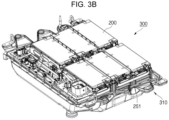
- FIGS. 3A and 3B show a battery pack according to one or more embodiments of the present disclosure.
- the battery pack may include a plurality of battery modules 200 and a housing 310 for accommodating the plurality of battery modules 200.
- the housing 310 may include first and second housings 311 and 312 coupled in opposite directions (e.g., upper and lower directions) around the plurality of battery modules 200.
- the plurality of battery modules 200 may be electrically connected to each other by using a bus bar 251 (shown in FIG. 3B ), and the plurality of battery modules 200 may be electrically connected to each other in series, in parallel, or a combination of series and parallel (i.e., a series-parallel mixed method), thereby obtaining desired (e.g., required) electrical output.
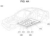
- FIGS. 4A and 4B show a vehicle body and vehicle body parts having a battery pack according to one or more embodiments of the present disclosure.
- a battery pack 300 may include a battery pack cover 311, which is a part of a vehicle underbody 410, and a pack frame 312 under the vehicle underbody 410.
- the pack frame 312 and the battery pack cover 311 may be integral with a vehicle floor 420 of the vehicle.
- the vehicle underbody 410 separates the inside and the outside of a vehicle, and the pack frame 312 may be outside the vehicle.
- FIG. 4B is a schematic side view of a vehicle according to one or more embodiments of the present disclosure.
- a vehicle 500 may be formed by combining additional parts, such as a hood 510 in front of the vehicle and fenders 520 respectively located in the front and rear of the vehicle to a vehicle body 400.
- the vehicle 500 may further include a vehicle floor 420, which is one of the vehicle body parts 400 including the battery pack 300, which includes the pack frame 312 and the battery pack cover 311.
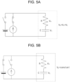
- FIGS. 5A to 5D illustrate a method for charging a secondary battery according to an embodiment of the present disclosure.
- a secondary battery may be charged and discharged by, for example, the following manner:
- CCCV charging is a charging method in which constant current (CC) charging is performed until the voltage reaches a suitable or reference voltage (e.g., a predetermined voltage), and then constant voltage (CV) charging is performed until the amount of current flowing decreases until the end current value is achieved.
- a suitable or reference voltage e.g., a predetermined voltage
- a switch of a constant current power supply is turned on and a switch of a constant voltage power supply is turned off so that a constant (or substantially constant) current I flows through the secondary battery.
- a secondary battery voltage VB may increase over time.
- CC charging is switched to CV charging.
- a suitable or reference voltage e.g., a predetermined voltage
- the switch of the constant voltage power supply is turned on and the switch of the constant current power supply is turned off so that the secondary battery voltage VB is constant (or substantially constant).
- the current I flowing through the secondary battery reaches a suitable or reference current (e.g., a predetermined current), for example, about (approximately) 0.01 C
- a suitable or reference current e.g., a predetermined current
- all switches are turned off and the current I becomes 0, as shown in FIG. 5C .
- the voltage VR applied to the internal resistor R becomes 0 V (or approximately 0 V). Accordingly, even when voltage drop is prevented across the internal resistor R, the secondary battery voltage VB substantially does not decrease (e.g., the secondary battery voltage VB is substantially constant).
- FIG. 5D shows a graph of a secondary battery voltage VB and charging current during CCCV charging and after CCCV charging is terminated. As illustrated in FIG. 5D , after CCCV charging is terminated, the secondary battery voltage VB substantially does not decrease (e.g., the secondary battery voltage VB is substantially constant after CCCV charging is terminated).
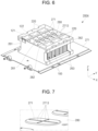
- FIG. 6 is a perspective view showing a battery module 200A according to an embodiment of the present disclosure
- FIG. 7 is an enlarged view of a partial area of FIG. 6
- FIG. 8 is an enlarged cross-sectional perspective view cut away from a portion of FIG. 6
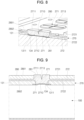
- FIG. 9 is an enlarged cross-sectional view cut away from a portion of FIG. 6 .
- the battery module 200A may include a plurality of battery cells 100, a heat-resistant portion 270, a bus bar holder 280, and bus bars 220.
- the plurality of battery cells 100 may be arranged in a horizontal direction (e.g., along the Y-axis direction).
- the plurality of battery cells 100 may be on a cooling member 271.
- the plurality of battery cells 100 may be fixed by housings 261, 262, and 263 (see FIG. 2 ).
- the side housing 263 may include an opening, and thus, some side portions of the battery cells 100 may be exposed to the outside through the opening.
- each of the plurality of battery cells 100 may include a cell vent 134 (or vent portion), a positive electrode terminal 121, and a negative electrode terminal 122 (see FIGS. 1A , 1B , and 2 ).
- the positive electrode terminal 121 and the negative electrode terminal 122 may be on opposite sides of the cell vent 134.
- the heat-resistant portion 270 may be potted on the plurality of battery cells 100.
- the heat-resistant portion 270 may include a plurality of heat-resistant vents 271 and a heat-resistant support portion 272 (see FIG. 9 ).
- the heat-resistant vents 271 may be provided in an area or areas corresponding to the cell vents 134 of the battery cells 100 (e.g., the heat-resistant vents 271 may be aligned or substantially aligned with the cell vents 134).
- Each of the heat-resistant vents 271 may include a substantially flat upper surface 2711 and a substantially flat lower surface 2712 that is opposite to the upper surface 2711.
- the heat-resistant support portion 272 may be outside the heat-resistant vents 271.
- the heat-resistant support portion 272 may include a substantially flat upper surface 2721 and a substantially flat lower surface 2722 that is opposite to the upper surface 2721. In one or more embodiments, the heat-resistant support portion 272 may be between the plurality of battery cells 100 and the bus bar holder 280. In one or more embodiments, the heat-resistant support portion 272 may be on (e.g., directly on) the cap plate 131 of the battery cells 100.
- Each of the heat-resistant vents 271 may include a notch 2713 having a depth.
- the notch 2713 may extend from the upper surface 2711 of the heat-resistant vent 271 downward toward the lower surface 2712. In one or more embodiments, the notch 2713 may become gradually smaller in width from the upper surface 2711 of the heat-resistant vent 271 to the lower surface 2712 of the heat-resistant vent 271.
- the depth of the notch 2713 may be approximately 1/3 to approximately 2/3 of the overall thickness of the heat-resistant vent 271. If the depth of the notch 2713 is less than approximately 1/3 of the overall thickness of the heat-resistant vent 271, the heat-resistant vent 271 may not be broken when an event (e.g., flame emission) occurs in any one of the battery cells 100, and thus, internal flames of the battery cell 100 may not be discharged to the outside. If the depth of the notch 2713 is greater (deeper) than approximately 2/3 of the overall thickness of the heat-resistant vent 271, the heat-resistant vent 271 may be too easily broken when a relatively small external impact is applied to the battery module 200A or the battery cell 100.
- an event e.g., flame emission
- the planar shape of the notch 2713 may include a single straight line, multiple parallel straight lines, or a cross shape. Due to the shape of the notch 2713, when an event occurs in the battery cell 100, the heat-resistant vent 271 may be easily broken and the internal flame of the battery cell 100 may be discharged to the outside.
- each of the heat-resistant vents 271 may be in close proximity to (e.g., in direct contact with) and/or adhered to one of the cell vents 134 of the battery cell 100. Therefore, when the cell vent 134 of the battery cell 100 is broken, the corresponding heat-resistant vent 271 may also be easily broken.
- the thickness of the heat-resistant vent 271 may be smaller than the thickness of the heat-resistant support portion 272.
- the upper surface 2711 of the heat-resistant vent 271 may be higher than the upper surface 2721 of the heat-resistant support portion 272.
- the heat-resistant vent 271 may protrude upward from the heat-resistant support portion 272.
- the upper surface 2711 of the heat-resistant vent 271 may be coplanar (or substantially coplanar) with the upper surface 2721 of the heat-resistant support portion 272.
- the lower surface 2712 of the heat-resistant vent 271 may be lower than the lower surface 2722 of the heat-resistant support portion 272. In one or more embodiments, the heat-resistant vent 271 may protrude downward from the heat-resistant support portion 272.
- the cell vent 134 may be coupled to the cell vent hole 1311 of the battery cell 100, and the corresponding heat-resistant vent 271 may be coupled to or inserted into the cell vent hole 1311.
- the cell vent 134 may be coupled to approximately the central area of the cell vent hole 1311 in the height direction (e.g., the Z-axis direction), and the heat-resistant vent 271 connected to the cell vent hole 1311 may extend to approximately the central area.
- the cell vent 134 may be coupled to approximately the lower region of the cell vent hole 1311 in the height direction (e.g., the Z-axis direction), and the heat-resistant vent 271 may extend to approximately the lower region of the cell vent hole 1311.
- the heat-resistant portion 270 may include epoxy or silicone.
- the epoxy may include an epoxy resin, a curing agent, and an inorganic filler.
- the silicone may include a silicone resin, a curing agent, and an inorganic filler.
- the inorganic filler relative to the total weight of the heat-resistant portion 270 may be approximately 5 wt% to approximately 95 wt%. If the weight ratio of the inorganic filler is less than approximately 5wt%, workability is excellent due to low viscosity, but heat resistance may be reduced.
- the inorganic filler may include nano- or micro-scale silica, alumina, glass fiber, magnesia, etc.
- the bus bar holder 280 may be on (e.g., directly on) the heat-resistant portion 270.
- the bus bar holder 280 may include a substantially flat upper surface 2801 and a substantially flat lower surface 2802 that is opposite to the upper surface 2801.
- the lower surface 2802 of the bus bar holder 280 may be in close proximity to (e.g., in contact or direct contact with) the upper surface 2721 of the heat-resistant support portion 272.
- the upper surface 2801 of the bus bar holder 280 may be exposed to the outside.
- the bus bar holder 280 may include holder vent holes 281 in areas corresponding to the locations of the heat-resistant vents 271, and bus bar holes 282 in areas corresponding to the locations of the positive electrode terminal 121 and the negative electrode terminal 122 of each of the battery cells 100.
- the bus bar holder 280 may be or include an insulating member or an insulating plate.
- the bus bar holder 280 may include polyethylene terephthalate (PET), high density polyethylene (HDPE), low density polyethylene (LDPE), polypropylene (PP), polystyrene (PS), or polyvinyl chloride (PVC).
- PET polyethylene terephthalate
- HDPE high density polyethylene
- LDPE low density polyethylene
- PP polypropylene
- PS polystyrene
- PVC polyvinyl chloride
- the bus bar holder 280 supports a plurality of bus bars 220, which will later be described, and prevents the battery cells 100 from directly electrically or mechanically contacting various electrical
- each of the heat-resistant vents 271 may protrude upward from the heat-resistant support portion 272.
- the heat-resistant vent 271 may be coupled to or inserted into the holder vent hole 281 of the bus bar holder 280.
- the lower surface 2712 of the heat-resistant vent 271 may be lower than the lower surface 2722 of the heat-resistant support portion 272.
- the heat-resistant vent 271 may protrude downward from the heat-resistant support portion 272.
- the upper surface 2711 of each of the heat-resistant vents 271 may be higher than the upper surface 2801 of the bus bar holder 280. In one or more embodiments, the upper surface 2711 of the heat-resistant vent 271 may be coplanar (or substantially coplanar) with the upper surface 2801 of the bus bar holder 280. In one or more embodiments, the upper surface 2711 of each of the heat-resistant vents 271 and the upper surface 2721 of the heat-resistant support portion 272 may be coplanar (or substantially coplanar) with each other. In one or more embodiments, the upper surface 2711 of each of the heat-resistant vents 271 may be coplanar (or substantially coplanar) with the lower surface 2802 of the bus bar holder 280. In one or more embodiments, the upper surface 2711 of each of the heat-resistant vents 271 may be located below the holder vent hole 281.
- the plurality of bus bars 220 may be on the heat-resistant portion 270 and electrically connected to the positive electrode terminal 121 and the negative electrode terminal 122 of the plurality of battery cells 100.
- one bus bar 220 may electrically connect the positive electrode terminal 121 of one-side battery cell 100a and the negative electrode terminal 122 of the other-side battery cell 100b such that the battery cells 100 are connected in series.
- one bus bar 220 may electrically connect the positive electrode terminal 121 (or the negative electrode terminal 122) of one-side battery cell 100a and the positive electrode terminal 121 (or the negative electrode terminal 122) of the other-side battery cell 100b such that the battery cells 100 are connected in parallel.
- each of the bus bars 220 may be located in one of the bus bar holes 282 of the bus bar holder 280.
- FIG. 10 is a flow chart showing a method for manufacturing a battery module 200A according to one embodiment of the present disclosure.
- the method for manufacturing the example battery module 200A according to one embodiment of the present disclosure may include the steps of: (S11) providing a plurality of battery cells 100; (S12) potting a heat-resistant portion 270; (S13) providing a bus bar holder 280; and (S14) providing a plurality of bus bars 220.
- each of the plurality of battery cells 100 may include a cell vent 134, a positive electrode terminal 121, and a negative electrode terminal 122.
- the heat-resistant portion 270 may be potted on the plurality of battery cells 100.
- heat-resistant epoxy or silicone in a liquid state may be potted through a dispenser and then cured.
- the heat-resistant material may be naturally cured for approximately 5 minutes to approximately 20 minutes.
- heat and/or light may be additionally provided to quickly cure the heat-resistant material. After the curing process, the heat-resistant portion 270 is substantially flat on the plurality of battery cells 100.
- the heat-resistant portion 270 may include heat-resistant vents 271 provided in areas corresponding to the positions of the cell vents 134 of the battery cells 100, and a heat-resistant support portion 272 provided on the cap plates 131 of the battery cells 100 outside the heat-resistant vents 271.
- a straight or cross-shaped notch 2713 may be formed on or in the heat-resistant vents 271 before curing the heat-resistant portion 270.
- a notching tool may be pressed onto the heat-resistant vents 271 prior to curing of the heat-resistant portion 270, thereby providing a notch 2713 in each of the heat-resistant vents 271 having a depth.
- the heat-resistant portion 270 may not be provided in an area corresponding to the positive electrode terminal 121 and the negative electrode terminal 122 of each of the battery cells 100. In one or more embodiments, the heat-resistant portion 270 may be potted and cured around the positive electrode terminal 121 and the negative electrode terminal 122 of each of the battery cells 100, and thus the heat resistant portion 270 may be exposed to the outside. In one or more embodiments, when potting the heat-resistant material, a fence or border may installed around the upper surface of the battery cells 100 to prevent the heat-resistant material from flowing into an unwanted area.
- the bus bar holder 280 may be provided on the heat-resistant portion 270. In one or more embodiments, the bus bar holder 280 may be provided prior to curing of heat-resistant portion 270. In one or more embodiments, the bus bar holder 280 may be provided after curing of heat-resistant portion 270. In one or more embodiments, the bus bar holder 280 may include holder vent holes 281 in areas corresponding to the heat-resistant vents 271, and bar holes 282 in areas corresponding to the positive electrode terminal 121 and the negative electrode terminal 122 of each of the battery cells 100.
- the positive electrode terminal 121 and the negative electrode terminal 122 of each of the plurality of battery cells 100 on the heat-resistant portion 270 may be connected to the bus bars 220.
- the positive electrode terminal 121 of one-side battery cell 100a and the negative electrode terminal 122 of the other-side battery cell 100b may be connected to the bus bar 220 such that the battery cells 100 are connected in series.
- the positive electrode terminal 121 of one-side battery cell 100a and the positive electrode terminal 121 of the other-side battery cell 100b may be connected to the bus bar 220 such that the battery cells 100 are connected in parallel.
- FIG. 11 is a flow chart showing a method for manufacturing a battery module 200A according to one embodiment of the present disclosure.
- the method for manufacturing the battery module 200A according to one embodiment of the present disclosure may include the steps of: (S21) providing a plurality of battery cells 100; (S22) providing a bus bar holder 280; (S23) potting a heat-resistant portion 270; and (S24) providing a plurality of bus bars 220.
- the manufacturing method shown in FIG. 11 is the same or similar to the manufacturing method shown in FIG. 10 , except that the order of the step of providing the bus bar holder 280 and the step of potting the heat-resistant portion 270 is changed. Therefore, only the differences will be explained.
- the bus bar holder 280 may be provided on the plurality of battery cells 100.
- the bus bar holder 280 may include a plurality of holder vent holes 281 provided in areas corresponding to the cell vents 134 of the battery cells 100, and a plurality of bus bar holes 282 provided in areas corresponding to a positive electrode terminal 121 and a negative electrode terminal 122 of the battery cells 100.
- the heat-resistant portion 270 may be potted in the space between the plurality of battery cells 100 and the bus bar holder 280.
- heat-resistant epoxy or silicone in a liquid state may be potted into the space between the plurality of battery cells 100 and the busbar holder 280 through a dispenser and then cured.
- the heat-resistant portion 270 may be substantially flat and may be provided between the plurality of battery cells 100 and the bus bar holder 280.
- the heat-resistant portion 270 may include a plurality of heat-resistant vents 271 and each heat-resistant vent 271 may be provided in an area corresponding to one of the cell vents 134 of one of the battery cells 100 and a corresponding holder vent hole 281 of the bus bar holder 280.
- the heat-resistant portion 270 may also include a heat-resistant support portion 272 provided between one of the battery cells 100 outside the corresponding heat-resistant vent 271 and the bus bar holder 280.
- a straight or cross-shaped notch 2713 may be provided on the heat-resistant vent 271 before curing the heat-resistant portion 270.
- a notching tool may be pressed onto the heat-resistant vent 271 before curing the heat-resistant portion 270, thereby providing the notch 2713 having a depth.
- a fence or border may be installed around the battery cells 100 and the bus bar holder 280 to prevent the heat-resistant material from flowing into an unwanted area.
Landscapes
- Chemical & Material Sciences (AREA)
- Chemical Kinetics & Catalysis (AREA)
- Electrochemistry (AREA)
- General Chemical & Material Sciences (AREA)
- Engineering & Computer Science (AREA)
- Manufacturing & Machinery (AREA)
- Aviation & Aerospace Engineering (AREA)
- Materials Engineering (AREA)
- Battery Mounting, Suspending (AREA)
Abstract
A battery module including battery cells arranged in a horizontal direction. Each of the battery cells includes a cell vent, a positive electrode terminal, and a negative electrode terminal. The battery module also includes a heat-resistant portion potted on the battery cells. The heat-resistant portion includes a heat-resistant vent provided in an area corresponding to the cell vent and a heat-resistant support portion provided outside the heat-resistant vent. The battery module also includes a bus bar holder on the heat-resistant portion. The bus bar holder includes a holder vent hole in an area corresponding to the heat-resistant vent and a bus bar hole in an area corresponding to the positive electrode terminal and the negative electrode terminal. The battery module further includes bus bars on the heat-resistant portion and connected to the positive and negative electrode terminals of the battery cells.
Description
- The present disclosure relates to a battery module.
- Unlike primary batteries that are not designed to be (re)charged, secondary (or rechargeable) batteries are batteries that are designed to be discharged and recharged. Low-capacity secondary batteries are used in portable, small electronic devices, such as smart phones, feature phones, notebook computers, digital cameras, and camcorders, while large-capacity secondary batteries are widely used as power sources for driving motors in hybrid vehicles and electric vehicles and for storing power (e.g., home and/or utility scale power storage). A secondary battery generally includes an electrode assembly composed of a positive electrode and a negative electrode, a case accommodating the same, and electrode terminals connected to the electrode assembly.
- The above information disclosed in this Background section is for enhancement of understanding of the background of the present disclosure, and therefore, it may contain information that does not constitute related (or prior) art.
- The present disclosure provides a battery module capable of preventing heat propagation and thermal runaway.
- These and other aspects and features of the present disclosure will be described in or will be apparent from the following description of embodiments of the present disclosure.
- A battery module according to an embodiment of the present disclosure for solving the technical problem may include: a plurality of battery cells arranged in a horizontal direction, each of the plurality of battery cells including a cell vent, a positive electrode terminal, and a negative electrode terminal; a heat-resistant portion potted on the plurality of battery cells, the heat-resistant portion including a heat-resistant vent provided in an area corresponding to the cell vent and a heat-resistant support portion provided outside the heat-resistant vent; a bus bar holder disposed on the heat-resistant portion, the bus bar holder including a holder vent hole provided in an area corresponding to the heat-resistant vent and a bus bar hole provided in an area corresponding to the positive electrode terminal and the negative electrode terminal; and a plurality of bus bars disposed on the heat-resistant portion and connected to the positive and negative electrode terminals of the plurality of battery cells.
- In some embodiments, the heat-resistant vent may include a notch.
- In some embodiments, the depth of the notch may be about 1/3 to about 2/3 of the thickness of the heat-resistant vent.
- In some embodiments, the planar shape of the notch may include a cross shape.
- In some embodiments, the heat-resistant vent may contact the cell vent.
- In some embodiments, the thickness of the heat-resistant vent may be greater than the thickness of the heat-resistant support portion.
- In some embodiments, the heat-resistant vent may protrude downward from the heat-resistant support portion.
- In some embodiments, the cell vent may be coupled to a lower portion of the cell vent hole of the battery cell, and the heat-resistant vent may be coupled to the cell vent hole.
- In some embodiments, the heat-resistant portion may include epoxy or silicone.
- In some embodiments, the upper surface of the heat-resistant vent and the upper surface of the heat-resistant support portion may be coplanar.
- In some embodiments, the heat-resistant vent may protrude upward from the heat-resistant support portion.
- In some embodiments, the heat-resistant vent may be coupled to the holder vent hole.
- In some embodiments, a surface of the heat-resistant vent may be coplanar with an upper surface of the bus bar holder.
- A method for manufacturing a battery module according to an embodiment of the present disclosure for solving the technical problem, may include: providing a plurality of battery cells arranged in a horizontal direction, each of the plurality of battery cells including a cell vent, a positive electrode terminal, and a negative electrode terminal; potting a heat-resistant portion on the plurality of battery cells, the heat-resistant portion including a heat-resistant vent provided in an area corresponding to the cell vent and a heat-resistant support portion provided outside the heat-resistant vent; providing a bus bar holder disposed on the heat-resistant portion, the bus bar holder including a holder vent hole provided in an area corresponding to the heat-resistant vent and a bus bar hole provided in an area corresponding to the positive electrode terminal and the negative electrode terminal; and providing a plurality of bus bars disposed on the heat-resistant portion and connecting the positive and negative electrode terminals of the plurality of battery cells.
- A method for manufacturing a battery module according to an embodiment of the present disclosure for solving the technical problem, may include: providing a plurality of battery cells arranged in a horizontal direction, each of the plurality of battery cells including a cell vent, a positive electrode terminal, and a negative electrode terminal; providing a bus bar holder disposed on the plurality of battery cells, the bus bar holder including a holder vent hole provided in an area corresponding to the cell vent and a bus bar hole provided in an area corresponding to the positive electrode terminal and the negative electrode terminal; potting a heat-resistant portion between the plurality of battery cells and the bus bar holder, the heat-resistant portion including a heat-resistant vent provided in an area corresponding to the cell vent and a heat-resistant support portion provided outside the heat-resistant vent; and providing a plurality of bus bars disposed on the heat-resistant portion and connecting the positive and negative electrode terminals of the plurality of battery cells.
- At least some of the above and other features of the invention are set out in the claims.
- As described above, according to the present invention, a battery module capable of preventing heat propagation and thermal runaway is provided.
- However, the aspects and features of the present disclosure are not limited to those described above, and other aspects and features not expressly described herein will be clearly understood by a person skilled in the art from the description of example embodiments of the present disclosure described below.
-
-
FIG. 1A is a perspective view of a prismatic battery according to an embodiment of the present disclosure; -
FIG. 1B is a cross-sectional view taken along theline 1b-1b inFIG. 1A . -
FIG. 2 is a perspective view of a battery module according to an embodiment of the present disclosure; -
FIGS. 3A and3B are perspective views of a battery pack according to an embodiment of the present disclosure; -
FIGS. 4A and4B show examples of vehicle bodies and body parts to which one or more embodiments of the present disclosure may be applied; -
FIGS. 5A to 5D illustrate a method for charging a secondary battery according to an embodiment of the present disclosure; -
FIG. 6 is a perspective view showing an example battery module according to the present disclosure. -
FIG. 7 is an enlarged view of a partial area ofFIG. 6 . -
FIG. 8 is an enlarged cross-sectional perspective view cut away from a portion ofFIG. 6 . -
FIG. 9 is an enlarged cross-sectional view cut away from a portion ofFIG. 6 . -
FIG. 10 is a flow chart showing a method for manufacturing an example battery module according to the present disclosure. -
FIG. 11 is a flow chart showing a method for manufacturing an example battery module according to the present disclosure. - Hereinafter, embodiments of the present disclosure will be described, in detail, with reference to the accompanying drawings. The terms or words used in this specification and claims should not be construed as being limited to the usual or dictionary meaning and should be interpreted as meaning and concept consistent with the technical idea of the present disclosure based on the principle that the inventor can be his/her own lexicographer to appropriately define the concept of the term to explain his/her invention in the best way.
- The embodiments described in this specification and the configurations shown in the drawings are only some of the embodiments of the present disclosure and do not represent all of the technical ideas, aspects, and features of the present disclosure. Accordingly, it should be understood that there may be various equivalents and modifications that can replace or modify the embodiments described herein at the time of filing this application.
- It will be understood that when an element or layer is referred to as being "on," "connected to," or "coupled to" another element or layer, it may be directly on, connected, or coupled to the other element or layer or one or more intervening elements or layers may also be present. When an element or layer is referred to as being "directly on," "directly connected to," or "directly coupled to" another element or layer, there are no intervening elements or layers present. For example, when a first element is described as being "coupled" or "connected" to a second element, the first element may be directly coupled or connected to the second element or the first element may be indirectly coupled or connected to the second element via one or more intervening elements.
- In the figures, dimensions of the various elements, layers, etc. may be exaggerated for clarity of illustration. The same reference numerals designate the same elements. As used herein, the term "and/or" includes any and all combinations of one or more of the associated listed items. Further, the use of "may" when describing embodiments of the present disclosure relates to "one or more embodiments of the present disclosure." Expressions, such as "at least one of" and "any one of," when preceding a list of elements, modify the entire list of elements and do not modify the individual elements of the list. When phrases such as "at least one of A, B and C, "at least one of A, B or C," "at least one selected from a group of A, B and C," or "at least one selected from among A, B and C" are used to designate a list of elements A, B and C, the phrase may refer to any and all suitable combinations or a subset of A, B and C, such as A, B, C, A and B, A and C, B and C, or A and B and C. As used herein, the terms "use," "using," and "used" may be considered synonymous with the terms "utilize," "utilizing," and "utilized," respectively. As used herein, the terms "substantially," "about," and similar terms are used as terms of approximation and not as terms of degree, and are intended to account for the inherent variations in measured or calculated values that would be recognized by those of ordinary skill in the art.
- It will be understood that, although the terms first, second, third, etc. may be used herein to describe various elements, components, regions, layers, and/or sections, these elements, components, regions, layers, and/or sections should not be limited by these terms. These terms are used to distinguish one element, component, region, layer, or section from another element, component, region, layer, or section. Thus, a first element, component, region, layer, or section discussed below could be termed a second element, component, region, layer, or section without departing from the teachings of example embodiments.
- Spatially relative terms, such as "beneath," "below," "lower," "above," "upper," and the like, may be used herein for ease of description to describe one element or feature's relationship to another element(s) or feature(s) as illustrated in the figures. It will be understood that the spatially relative terms are intended to encompass different orientations of the device in use or operation in addition to the orientation depicted in the figures. For example, if the device in the figures is turned over, elements described as "below" or "beneath" other elements or features would then be oriented "above" or "over" the other elements or features. Thus, the term "below" may encompass both an orientation of above and below. The device may be otherwise oriented (rotated 90 degrees or at other orientations), and the spatially relative descriptors used herein should be interpreted accordingly.
- The terminology used herein is for the purpose of describing embodiments of the present disclosure and is not intended to be limiting of the present disclosure. As used herein, the singular forms "a" and "an" are intended to include the plural forms as well, unless the context clearly indicates otherwise. It will be further understood that the terms "includes," "including," "comprises," and/or "comprising," when used in this specification, specify the presence of stated features, integers, steps, operations, elements, and/or components but do not preclude the presence or addition of one or more other features, integers, steps, operations, elements, components, and/or groups thereof.
- Also, any numerical range disclosed and/or recited herein is intended to include all sub-ranges of the same numerical precision subsumed within the recited range. For example, a range of "1.0 to 10.0" is intended to include all subranges between (and including) the recited minimum value of 1.0 and the recited maximum value of 10.0, that is, having a minimum value equal to or greater than 1.0 and a maximum value equal to or less than 10.0, such as, for example, 2.4 to 7.6. Any maximum numerical limitation recited herein is intended to include all lower numerical limitations subsumed therein, and any minimum numerical limitation recited in this specification is intended to include all higher numerical limitations subsumed therein. Accordingly, Applicant reserves the right to amend this specification, including the claims, to expressly recite any sub-range subsumed within the ranges expressly recited herein.
- References to two compared elements, features, etc. as being "the same" may mean that they are "substantially the same". Thus, the phrase "substantially the same" may include a case having a deviation that is considered low in the art, for example, a deviation of 5% or less. In addition, when a certain parameter is referred to as being uniform in a given region, it may mean that it is uniform in terms of an average.
- Throughout the specification, unless otherwise stated, each element may be singular or plural.
- When an arbitrary element is referred to as being disposed (or located or positioned) on the "above (or below)" or "on (or under)" a component, it may mean that the arbitrary element is placed in contact with the upper (or lower) surface of the component and may also mean that another component may be interposed between the component and any arbitrary element disposed (or located or positioned) on (or under) the component.
- In addition, it will be understood that when an element is referred to as being "coupled," "linked" or "connected" to another element, the elements may be directly "coupled," "linked" or "connected" to each other, or an intervening element may be present therebetween, through which the element may be "coupled," "linked" or "connected" to another element. In addition, when a part is referred to as being "electrically coupled" to another part, the part can be directly connected to another part or an intervening part may be present therebetween such that the part and another part are indirectly connected to each other.
- Throughout the specification, when "A and/or B" is stated, it means A, B or A and B, unless otherwise stated. That is, "and/or" includes any or all combinations of a plurality of items enumerated. When "C to D" is stated, it means C or more and D or less, unless otherwise specified.
- A battery pack according to one or more embodiments includes at least one battery module and a pack housing having an accommodation space in which the at least one battery module is accommodated.
- The battery module may include a plurality of battery cells and a module housing. The battery cells may be accommodated inside the module housing in a stacked form (or stacked arrangement or configuration). Each battery cell may have a positive electrode terminal and a negative electrode terminal and may be a circular type, a prismatic type, or a pouch type according to the shape of battery. In the present specification, a battery cell may also be referred to as a secondary battery, a battery, or a cell.
- In the battery pack, one cell stack may constitute one module stacked in place of the battery module. The cell stack may be accommodated in an accommodation space of the pack housing or may be accommodated in an accommodation space partitioned by a frame, a partition wall, etc.
- The battery cell may generate a large amount of heat during charging/discharging. The generated heat may be accumulated in the battery cell, thereby accelerating the deterioration of the battery cell. Accordingly, the battery pack may further include a cooling member to remove the generated heat and thereby suppress deterioration of the battery cell. The cooling member may be provided at the bottom of the accommodation space at where the battery cell is provided but is not limited thereto and may be provided at the top or side depending on the battery pack.
- The battery cell may be configured such that exhaust gas generated inside the battery cell under abnormal operating conditions, also known as thermal runaway or thermal events, is discharged to the outside of the battery cell. The battery pack or the battery module may include an exhaust port for discharging the exhaust gas to prevent or reduce damage to the battery pack or module by the exhaust gas.
- The battery pack may include a battery and a battery management system (BMS) for managing the battery. The battery management system may include a detection device, a balancing device, and a control device. The battery module may include a plurality of cells connected to each other in series and/or parallel. The battery modules may be connected to each other in series and/or in parallel.
- The detection device may detect a state of a battery (e.g., voltage, current, temperature, etc.) to output state information indicating the state of the battery. The detection device may detect the voltage of each cell constituting the battery or of each battery module. The detection device may detect current flowing through each battery module constituting the battery module or the battery pack. The detection device may also detect the temperature of a cell and/or module on at least one point of the battery and/or an ambient temperature.
- The balancing device may perform a balancing operation of a battery module and/or cells constituting the battery module. The control device may receive state information (e.g., voltage, current, temperature, etc.) of the battery module from the detection device. The control device may monitor and calculate the state of the battery module (e.g., voltage, current, temperature, state of charge (SOC), life span (state of health (SOH)), etc.) on the basis of the state information received from the detection device. In addition, on the basis of the monitored state information, the control device may perform a control function (e.g., temperature control, balancing control, charge/discharge control, etc.) and a protection function (e.g., over-discharge, overcharge, over-current protection, short circuit, fire extinguishing function, etc.). In addition, the control device may perform a wired or wireless communication function with an external device of the battery pack (e.g., a higher level controller or vehicle, charger, power conversion system, etc.).
- The control device may control charging/discharging operation and protection operation of the battery. To this end, the control device may include a charge/discharge control unit, a balancing control unit, and/or a protection unit.
- The battery management system is a system that monitors the battery state and performs diagnosis and control, communication, and protection functions, and may calculate the charge/discharge state, calculate battery life or state of health (SOH), cut off, as necessary, battery power (e.g., relay control), control thermal management (e.g., cooling, heating, etc.), perform a high-voltage interlock function, and/or may detect and/or calculate insulation and short circuit conditions.
- A relay may be a mechanical contactor that is turned on and off by the magnetic force of a coil or a semiconductor switch, such as a metal oxide semiconductor field effect transistor (MOSFET).
- The relay control has a function of cutting off the power supply from the battery if (or when) a problem occurs in the vehicle and the battery system and may include one or more relays and pre-charge relays at the positive terminal and the negative terminal, respectively.
- In the pre-charge control, there is a risk of inrush current occurring in the high-voltage capacitor on the input side of the inverter when the battery load is connected. Thus, to prevent inrush current when starting a vehicle, the pre-charge relay may be operated before connecting the main relay and the pre-charge resistor may be connected.
- The high-voltage interlock is a circuit that uses a small signal to detect whether or not all high-voltage parts of the entire vehicle system are connected and may have a function of forcibly opening a relay if (or when) an opening occurs at even one location on the entire loop.
-
FIGS. 1A is a perspective view illustrating a secondary battery according to one or more embodiments of the present disclosure, andFIG. 1B is a cross-sectional view taken along theline 1b-1b inFIG. 1A . - Referring to
FIGS. 1A and1B , thesecondary battery 100 according to one or more embodiments of the present disclosure may include at least oneelectrode assembly 110 wound with aseparator 113 as an insulator between thepositive electrode 111 and thenegative electrode 112, acase 120 in which theelectrode assembly 110 is received (or accommodated) therein, and acap assembly 130 coupled to an opening of thecase 120. - The
secondary battery 100 according to one or more embodiments illustrated inFIGS. 1A and1B will now be described as an example of a prismatic lithium-ion secondary battery. However, the present disclosure is not limited thereto, and suitable aspects, features and principles described herein may be applied to various other types of batteries, such as lithium polymer batteries and/or cylindrical batteries. - Each of the
positive electrode 111 and thenegative electrode 112 may include a current collector made of a thin metal foil having a coated portion on which an active material is coated and anuncoated portion - The
positive electrode 111 and thenegative electrode 112 are wound after positioning theseparator 113, which is an insulator, therebetween. However, the present disclosure is not limited thereto, and theelectrode assembly 110 may have a structure in which apositive electrode 111 and anegative electrode 112, each made of a plurality of sheets, are alternately stacked with a separator positioned therebetween. - The
case 120 may form the overall outer appearance of thesecondary battery 100 and may be made of a conductive metal, such as aluminum, aluminum alloy, or nickel-plated steel. In addition, thecase 120 may provide an interior space in which theelectrode assembly 110 is accommodated. - The
cap assembly 130 may include acap plate 131 covering an opening in thecase 120, and thecase 120 and thecap plate 131 may be made of a conductive material. The positive andnegative electrode terminals positive electrode 111 and thenegative electrode 112, respectively, may penetrate (or extend through) thecap plate 131 and protrude outwardly therethrough. - In addition, outer peripheral surfaces (e.g., circumferential surfaces) of upper pillars of the positive and
negative electrode terminals cap plate 131 may be threaded and may be fixed to thecap plate 131 utilizing nuts. - However, the present disclosure is not limited thereto, and the positive and
negative electrode terminals cap plate 131. - In addition, the
cap plate 131 may be made of a thin plate and may be coupled to the opening in thecase 120, and anelectrolyte injection port 132 into which a sealingstopper 133 may be installed may be located (e.g., formed) in thecap plate 131, and avent portion 134 having anotch 134a may be provided in thecap plate 131. - The positive and
negative electrode terminals current collectors 140 and 150 (hereinafter referred to as positive and negative current collectors, respectively) by being bonded or coupled (e.g., by welding) to the positiveuncoated portion 111a and the negative electrodeuncoated portion 112a, respectively. - In one or more embodiments, the positive and
negative electrode terminals current collectors negative electrode terminals current collectors - In addition, an insulation member may be between the
electrode assembly 110 and thecap plate 131. The insulation member may include first and secondlower insulation members lower insulation members electrode assembly 110 and thecase 120. - In addition, according to one or more embodiments of the present disclosure, one end of a
separation member electrode assembly 110 and may be between one of theinsulation members negative electrode terminals - In one or more embodiments, the separation member may include first and
second separation members - In one or more embodiments, first ends of the first and
second separation members electrode assembly 110 may be installed between one of the first and secondlower insulation members negative electrode terminals - Accordingly, the positive and
negative electrode terminals current collectors lower insulation members second separation members -
FIG. 2 is a perspective view illustrating a battery module according to one or more embodiments of the present disclosure. - Referring to
FIG. 2 , thebattery module 200 according to one or more embodiments of the present disclosure includeselectrode units battery cells 100 arranged in one direction, a plurality ofconnection tabs 220 each connecting abattery cell 100a to anadjacent battery cell 100b, and aprotection circuit module 230 connected to theconnection tabs 220. Theprotection circuit module 230 may include a battery management system (BMS). In one or more embodiments, each of theconnection tabs 220 may include a body portion in contact with theelectrode units adjacent battery cells protection circuit module 230. Theconnection tab 220 may be, for example, a bus bar. - Each
battery cell 100 may include a battery case, an electrode assembly received (or accommodated) in the battery case, and an electrolyte. The electrode assembly and the electrolyte react electrochemically to store and release (e.g., generate) energy.Terminal parts connection tab 220 and avent 134 configured to form a discharge passage for gas generated inside the battery case may be provided on one side of (e.g., an upper side of) thebattery cell 100. Theterminal parts battery cell 100 may be apositive electrode terminal 121 and anegative electrode terminal 122 having different polarities from each other, and theterminal parts adjacent battery cells connection tabs 220, to be described in more detail below. Although a serial connection has been described as an embodiment, the connection structure is not limited thereto, and various connection structures may be employed in other embodiments. In addition, the number and arrangement of battery cells is not limited to the structure shown inFIG. 2 and may be changed as desired or necessary. - The plurality of
battery cells 100 may be arranged in (e.g., may be stacked in) one direction so that the wide surfaces of thebattery cells 100 face each other, and the plurality ofbattery cells 100 may be fixed by thehousings housings end plates battery cells 100 and a pair ofside plates 263 facing the narrow surfaces of thebattery cells 100 and abottom plate 264 connecting the pair ofend plates side plates 263 may support side surfaces (i.e., the narrow surfaces) of thebattery cells 100, and thebottom plate 264 may support bottom surfaces of thebattery cells 100. In addition, the pair ofend plates side plates 263, and thebottom plate 264 may be connected bybolts 265 and/or any other suitable fastening members and/or methods known to those of ordinary skill in the art. - The
protection circuit module 230 may have electronic components and protection circuits mounted thereon and may be electrically connected to theconnection tabs 220, to be described in more detail later. Theprotection circuit module 230 includes a firstprotection circuit module 230a and a secondprotection circuit module 230b extending along the direction in which the plurality ofbattery cells 100 are arranged in different locations (e.g., extending along the Y-direction). The firstprotection circuit module 230a and the secondprotection circuit module 230b may be spaced from each other (e.g., in the X-direction) at a suitable interval (e.g., a predetermined interval) and arranged parallel (or approximately parallel) to each other to be electrically connected to different sets of theconnection tabs 220. In one or more embodiments, the firstprotection circuit module 230a extends on one side of the upper portion of the plurality ofbattery cells 100 along the direction in which the plurality ofbattery cells 100 are arranged (e.g., the Y-direction), and the secondprotection circuit module 230b extends to the other upper side of the plurality ofbattery cells 100 along the direction in which the plurality ofbattery cells 100 are arranged. The secondprotection circuit module 230b may be spaced from the firstprotection circuit module 230a at a suitable interval (e.g., a predetermined interval) with thevents 134 between the first and secondprotection circuit modules vents 134 may be parallel to the first and secondprotection circuit modules protection circuit modules battery cells 100 are arranged (e.g., the Y-direction), thereby reducing or minimizing the area of the printed circuit board (PCB) constituting the protection circuit module. By separately configuring the protection circuit module into twoprotection circuit modules protection circuit module 230a and the secondprotection circuit module 230b may be connected to each other by aconductive connection member 250. One side of theconductive connection member 250 is connected to the firstprotection circuit module 230a, and the other side of theconductive connection member 250 is connected to the secondprotection circuit module 230b so that the twoprotection circuit modules - The connection may be performed by soldering, resistance welding, laser welding, projection welding and/or any other suitable connection methods known to those of ordinary skill in the art.
- In one or more embodiments, the
connection member 250 may be, for example, an electric wire. In addition, theconnection member 250 may be made of a material having elasticity or flexibility. The connectingmember 250 enables checking and/or managing whether the voltage, temperature, and/or current of the plurality ofbattery cells 100 are normal. In one or more embodiments, the information received by the firstprotection circuit module 230a fromconnection tabs 220 adjacent to the firstprotection circuit module 230a, such as voltage, current, and/or temperature, and the information received by the secondprotection circuit module 230b fromconnection tabs 220 adjacent to the secondprotection circuit module 230b, such as voltage, current, and/or temperature, may be integrated and managed by theprotection circuit module 230 through theconnection member 250. - In addition, when the
battery cell 100 swells, shocks may be absorbed by the elasticity or flexibility of theconnection member 250, thereby preventing the first and secondprotection circuit modules - In addition, the shape and structure of the
connection member 250 is not limited to the shape and structure shown inFIG. 2 . - As described above, because the
protection circuit module 230 is provided as the first and secondprotection circuit modules protection circuit module 230 can be reduced or minimized, and the space inside thebattery module 200 can be accessed which improves work efficiency by facilitating connecting theconnection tabs 220 and theprotection circuit module 230 and performing repair work if (or when) an abnormality is detected in thebattery module 200. -
FIGS. 3A and3B show a battery pack according to one or more embodiments of the present disclosure. - The battery pack may include a plurality of
battery modules 200 and ahousing 310 for accommodating the plurality ofbattery modules 200. In one or more embodiments, thehousing 310 may include first andsecond housings battery modules 200. The plurality ofbattery modules 200 may be electrically connected to each other by using a bus bar 251 (shown inFIG. 3B ), and the plurality ofbattery modules 200 may be electrically connected to each other in series, in parallel, or a combination of series and parallel (i.e., a series-parallel mixed method), thereby obtaining desired (e.g., required) electrical output. -
FIGS. 4A and4B show a vehicle body and vehicle body parts having a battery pack according to one or more embodiments of the present disclosure. - In
FIG. 4A , abattery pack 300 may include abattery pack cover 311, which is a part of avehicle underbody 410, and apack frame 312 under thevehicle underbody 410. Thepack frame 312 and thebattery pack cover 311 may be integral with avehicle floor 420 of the vehicle. - The
vehicle underbody 410 separates the inside and the outside of a vehicle, and thepack frame 312 may be outside the vehicle. -
FIG. 4B is a schematic side view of a vehicle according to one or more embodiments of the present disclosure. - A
vehicle 500 may be formed by combining additional parts, such as ahood 510 in front of the vehicle andfenders 520 respectively located in the front and rear of the vehicle to avehicle body 400. - The
vehicle 500 may further include avehicle floor 420, which is one of thevehicle body parts 400 including thebattery pack 300, which includes thepack frame 312 and thebattery pack cover 311. -
FIGS. 5A to 5D illustrate a method for charging a secondary battery according to an embodiment of the present disclosure. A secondary battery may be charged and discharged by, for example, the following manner: - CCCV charging is a charging method in which constant current (CC) charging is performed until the voltage reaches a suitable or reference voltage (e.g., a predetermined voltage), and then constant voltage (CV) charging is performed until the amount of current flowing decreases until the end current value is achieved.
- During CC charging, as shown in
FIG. 5A , a switch of a constant current power supply is turned on and a switch of a constant voltage power supply is turned off so that a constant (or substantially constant) current I flows through the secondary battery. During the CC charging process, because the current I is constant, a voltage VR applied to an internal resistor R is also constant according to Ohm's law (VR=R×I). Additionally, a voltage VC applied to a secondary battery capacitor C increases with time. Therefore, a secondary battery voltage VB may increase over time. - When (or if) the secondary battery voltage VB reaches a suitable or reference voltage (e.g., a predetermined voltage), for example, about (approximately) 4.3 V, CC charging is switched to CV charging. During CV charging, as shown in
FIG. 5B , the switch of the constant voltage power supply is turned on and the switch of the constant current power supply is turned off so that the secondary battery voltage VB is constant (or substantially constant). The voltage VC applied to the secondary battery capacitor C increases with time. Because VB = VR + VC, the voltage VR applied to the internal resistor R decreases with time. As the voltage VR applied to the internal resistor R decreases, the current I flowing through the secondary battery may also decrease according to Ohm's law (VR=R×I). - When (or if) the current I flowing through the secondary battery reaches a suitable or reference current (e.g., a predetermined current), for example, about (approximately) 0.01 C, charging is terminated. When (or if) CCCV charging is finished, all switches are turned off and the current I becomes 0, as shown in
FIG. 5C . Thus, the voltage VR applied to the internal resistor R becomes 0 V (or approximately 0 V). Accordingly, even when voltage drop is prevented across the internal resistor R, the secondary battery voltage VB substantially does not decrease (e.g., the secondary battery voltage VB is substantially constant). -
FIG. 5D shows a graph of a secondary battery voltage VB and charging current during CCCV charging and after CCCV charging is terminated. As illustrated inFIG. 5D , after CCCV charging is terminated, the secondary battery voltage VB substantially does not decrease (e.g., the secondary battery voltage VB is substantially constant after CCCV charging is terminated). -
FIG. 6 is a perspective view showing abattery module 200A according to an embodiment of the present disclosure,FIG. 7 is an enlarged view of a partial area ofFIG. 6 ,FIG. 8 is an enlarged cross-sectional perspective view cut away from a portion ofFIG. 6 , andFIG. 9 is an enlarged cross-sectional view cut away from a portion ofFIG. 6 . - As shown in
FIGS. 6 to 9 , thebattery module 200A according to one embodiment of the present disclosure may include a plurality ofbattery cells 100, a heat-resistant portion 270, abus bar holder 280, and bus bars 220. - The plurality of
battery cells 100 may be arranged in a horizontal direction (e.g., along the Y-axis direction). - As described above, the plurality of
battery cells 100 may be on a coolingmember 271. In addition, as described above, the plurality ofbattery cells 100 may be fixed byhousings FIG. 2 ). In one or more embodiments, theside housing 263 may include an opening, and thus, some side portions of thebattery cells 100 may be exposed to the outside through the opening. - As described above, each of the plurality of
battery cells 100 may include a cell vent 134 (or vent portion), apositive electrode terminal 121, and a negative electrode terminal 122 (seeFIGS. 1A ,1B , and2 ). In one or more embodiments, for each of thebattery cells 100, thepositive electrode terminal 121 and thenegative electrode terminal 122 may be on opposite sides of thecell vent 134. - The heat-
resistant portion 270 may be potted on the plurality ofbattery cells 100. The heat-resistant portion 270 may include a plurality of heat-resistant vents 271 and a heat-resistant support portion 272 (seeFIG. 9 ). The heat-resistant vents 271 may be provided in an area or areas corresponding to the cell vents 134 of the battery cells 100 (e.g., the heat-resistant vents 271 may be aligned or substantially aligned with the cell vents 134). Each of the heat-resistant vents 271 may include a substantially flatupper surface 2711 and a substantially flatlower surface 2712 that is opposite to theupper surface 2711. The heat-resistant support portion 272 may be outside the heat-resistant vents 271. The heat-resistant support portion 272 may include a substantially flatupper surface 2721 and a substantially flatlower surface 2722 that is opposite to theupper surface 2721. In one or more embodiments, the heat-resistant support portion 272 may be between the plurality ofbattery cells 100 and thebus bar holder 280. In one or more embodiments, the heat-resistant support portion 272 may be on (e.g., directly on) thecap plate 131 of thebattery cells 100. - Each of the heat-
resistant vents 271 may include anotch 2713 having a depth. In one or more embodiments, thenotch 2713 may extend from theupper surface 2711 of the heat-resistant vent 271 downward toward thelower surface 2712. In one or more embodiments, thenotch 2713 may become gradually smaller in width from theupper surface 2711 of the heat-resistant vent 271 to thelower surface 2712 of the heat-resistant vent 271. - In one or more embodiments, the depth of the
notch 2713 may be approximately 1/3 to approximately 2/3 of the overall thickness of the heat-resistant vent 271. If the depth of thenotch 2713 is less than approximately 1/3 of the overall thickness of the heat-resistant vent 271, the heat-resistant vent 271 may not be broken when an event (e.g., flame emission) occurs in any one of thebattery cells 100, and thus, internal flames of thebattery cell 100 may not be discharged to the outside. If the depth of thenotch 2713 is greater (deeper) than approximately 2/3 of the overall thickness of the heat-resistant vent 271, the heat-resistant vent 271 may be too easily broken when a relatively small external impact is applied to thebattery module 200A or thebattery cell 100. - In one or more embodiments, the planar shape of the
notch 2713 may include a single straight line, multiple parallel straight lines, or a cross shape. Due to the shape of thenotch 2713, when an event occurs in thebattery cell 100, the heat-resistant vent 271 may be easily broken and the internal flame of thebattery cell 100 may be discharged to the outside. - In one or more embodiments, each of the heat-
resistant vents 271 may be in close proximity to (e.g., in direct contact with) and/or adhered to one of the cell vents 134 of thebattery cell 100. Therefore, when thecell vent 134 of thebattery cell 100 is broken, the corresponding heat-resistant vent 271 may also be easily broken. - In one or more embodiments, the thickness of the heat-resistant vent 271 (or at least the thickness of the heat-
resistant vent 271 at the notch 2713) may be smaller than the thickness of the heat-resistant support portion 272. In one or more embodiments, theupper surface 2711 of the heat-resistant vent 271 may be higher than theupper surface 2721 of the heat-resistant support portion 272. In one or more embodiments, the heat-resistant vent 271 may protrude upward from the heat-resistant support portion 272. In one or more embodiments, theupper surface 2711 of the heat-resistant vent 271 may be coplanar (or substantially coplanar) with theupper surface 2721 of the heat-resistant support portion 272. In one or more embodiments, thelower surface 2712 of the heat-resistant vent 271 may be lower than thelower surface 2722 of the heat-resistant support portion 272. In one or more embodiments, the heat-resistant vent 271 may protrude downward from the heat-resistant support portion 272. - In one or more embodiments, the
cell vent 134 may be coupled to thecell vent hole 1311 of thebattery cell 100, and the corresponding heat-resistant vent 271 may be coupled to or inserted into thecell vent hole 1311. In one or more embodiments, thecell vent 134 may be coupled to approximately the central area of thecell vent hole 1311 in the height direction (e.g., the Z-axis direction), and the heat-resistant vent 271 connected to thecell vent hole 1311 may extend to approximately the central area. In one or more embodiments, thecell vent 134 may be coupled to approximately the lower region of thecell vent hole 1311 in the height direction (e.g., the Z-axis direction), and the heat-resistant vent 271 may extend to approximately the lower region of thecell vent hole 1311. - In one or more embodiments, the heat-
resistant portion 270 may include epoxy or silicone. In one or more embodiments, the epoxy may include an epoxy resin, a curing agent, and an inorganic filler. In one or more embodiments, the silicone may include a silicone resin, a curing agent, and an inorganic filler. The inorganic filler relative to the total weight of the heat-resistant portion 270 may be approximately 5 wt% to approximately 95 wt%. If the weight ratio of the inorganic filler is less than approximately 5wt%, workability is excellent due to low viscosity, but heat resistance may be reduced. If the weight ratio of the inorganic filler is greater than approximately 95 wt%, heat resistance is excellent, but workability may be reduced due to high viscosity. The inorganic filler may include nano- or micro-scale silica, alumina, glass fiber, magnesia, etc. - The
bus bar holder 280 may be on (e.g., directly on) the heat-resistant portion 270. Thebus bar holder 280 may include a substantially flatupper surface 2801 and a substantially flatlower surface 2802 that is opposite to theupper surface 2801. In one or more embodiments, thelower surface 2802 of thebus bar holder 280 may be in close proximity to (e.g., in contact or direct contact with) theupper surface 2721 of the heat-resistant support portion 272. In one or more embodiments, theupper surface 2801 of thebus bar holder 280 may be exposed to the outside. In one or more embodiments, thebus bar holder 280 may include holder vent holes 281 in areas corresponding to the locations of the heat-resistant vents 271, and bus bar holes 282 in areas corresponding to the locations of thepositive electrode terminal 121 and thenegative electrode terminal 122 of each of thebattery cells 100. Thebus bar holder 280 may be or include an insulating member or an insulating plate. Thebus bar holder 280 may include polyethylene terephthalate (PET), high density polyethylene (HDPE), low density polyethylene (LDPE), polypropylene (PP), polystyrene (PS), or polyvinyl chloride (PVC). Thebus bar holder 280 supports a plurality ofbus bars 220, which will later be described, and prevents thebattery cells 100 from directly electrically or mechanically contacting various electrical components located outside thebattery module 200A. - In one or more embodiments, each of the heat-
resistant vents 271 may protrude upward from the heat-resistant support portion 272. In one or more embodiments, the heat-resistant vent 271 may be coupled to or inserted into theholder vent hole 281 of thebus bar holder 280. In one or more embodiments, thelower surface 2712 of the heat-resistant vent 271 may be lower than thelower surface 2722 of the heat-resistant support portion 272. In one or more embodiments, the heat-resistant vent 271 may protrude downward from the heat-resistant support portion 272. - In one or more embodiments, the
upper surface 2711 of each of the heat-resistant vents 271 may be higher than theupper surface 2801 of thebus bar holder 280. In one or more embodiments, theupper surface 2711 of the heat-resistant vent 271 may be coplanar (or substantially coplanar) with theupper surface 2801 of thebus bar holder 280. In one or more embodiments, theupper surface 2711 of each of the heat-resistant vents 271 and theupper surface 2721 of the heat-resistant support portion 272 may be coplanar (or substantially coplanar) with each other. In one or more embodiments, theupper surface 2711 of each of the heat-resistant vents 271 may be coplanar (or substantially coplanar) with thelower surface 2802 of thebus bar holder 280. In one or more embodiments, theupper surface 2711 of each of the heat-resistant vents 271 may be located below theholder vent hole 281. - The plurality of
bus bars 220 may be on the heat-resistant portion 270 and electrically connected to thepositive electrode terminal 121 and thenegative electrode terminal 122 of the plurality ofbattery cells 100. In one or more embodiments, onebus bar 220 may electrically connect thepositive electrode terminal 121 of one-side battery cell 100a and thenegative electrode terminal 122 of the other-side battery cell 100b such that thebattery cells 100 are connected in series. In one or more embodiments, onebus bar 220 may electrically connect the positive electrode terminal 121 (or the negative electrode terminal 122) of one-side battery cell 100a and the positive electrode terminal 121 (or the negative electrode terminal 122) of the other-side battery cell 100b such that thebattery cells 100 are connected in parallel. In one or more embodiments, each of the bus bars 220 may be located in one of the bus bar holes 282 of thebus bar holder 280. -
FIG. 10 is a flow chart showing a method for manufacturing abattery module 200A according to one embodiment of the present disclosure. As shown inFIG. 10 , the method for manufacturing theexample battery module 200A according to one embodiment of the present disclosure may include the steps of: (S11) providing a plurality ofbattery cells 100; (S12) potting a heat-resistant portion 270; (S13) providing abus bar holder 280; and (S14) providing a plurality of bus bars 220. - In the step (S11) of providing a plurality of
battery cells 100, the plurality ofbattery cells 100 arranged in the horizontal direction (e.g., the Y-axis direction) may be provided. In one or more embodiments, each of the plurality ofbattery cells 100 may include acell vent 134, apositive electrode terminal 121, and anegative electrode terminal 122. - In the step (S12) of potting a heat-
resistant portion 270, the heat-resistant portion 270 may be potted on the plurality ofbattery cells 100. In one or more embodiments, heat-resistant epoxy or silicone in a liquid state may be potted through a dispenser and then cured. In one or more embodiments, the heat-resistant material may be naturally cured for approximately 5 minutes to approximately 20 minutes. In one or more embodiments, heat and/or light may be additionally provided to quickly cure the heat-resistant material. After the curing process, the heat-resistant portion 270 is substantially flat on the plurality ofbattery cells 100. The heat-resistant portion 270 may include heat-resistant vents 271 provided in areas corresponding to the positions of the cell vents 134 of thebattery cells 100, and a heat-resistant support portion 272 provided on thecap plates 131 of thebattery cells 100 outside the heat-resistant vents 271. In one or more embodiments, a straight orcross-shaped notch 2713 may be formed on or in the heat-resistant vents 271 before curing the heat-resistant portion 270. In one or more embodiments, a notching tool may be pressed onto the heat-resistant vents 271 prior to curing of the heat-resistant portion 270, thereby providing anotch 2713 in each of the heat-resistant vents 271 having a depth. In one or more embodiments, the heat-resistant portion 270 may not be provided in an area corresponding to thepositive electrode terminal 121 and thenegative electrode terminal 122 of each of thebattery cells 100. In one or more embodiments, the heat-resistant portion 270 may be potted and cured around thepositive electrode terminal 121 and thenegative electrode terminal 122 of each of thebattery cells 100, and thus the heatresistant portion 270 may be exposed to the outside. In one or more embodiments, when potting the heat-resistant material, a fence or border may installed around the upper surface of thebattery cells 100 to prevent the heat-resistant material from flowing into an unwanted area. - In the step (S13) of providing the
bus bar holder 280, thebus bar holder 280 may be provided on the heat-resistant portion 270. In one or more embodiments, thebus bar holder 280 may be provided prior to curing of heat-resistant portion 270. In one or more embodiments, thebus bar holder 280 may be provided after curing of heat-resistant portion 270. In one or more embodiments, thebus bar holder 280 may include holder vent holes 281 in areas corresponding to the heat-resistant vents 271, and barholes 282 in areas corresponding to thepositive electrode terminal 121 and thenegative electrode terminal 122 of each of thebattery cells 100. - In the step (S14) of providing the bus bars 220, the
positive electrode terminal 121 and thenegative electrode terminal 122 of each of the plurality ofbattery cells 100 on the heat-resistant portion 270 may be connected to the bus bars 220. In one or more embodiments, thepositive electrode terminal 121 of one-side battery cell 100a and thenegative electrode terminal 122 of the other-side battery cell 100b may be connected to thebus bar 220 such that thebattery cells 100 are connected in series. In one or more embodiments, thepositive electrode terminal 121 of one-side battery cell 100a and thepositive electrode terminal 121 of the other-side battery cell 100b may be connected to thebus bar 220 such that thebattery cells 100 are connected in parallel. -
FIG. 11 is a flow chart showing a method for manufacturing abattery module 200A according to one embodiment of the present disclosure. As shown inFIG. 11 , the method for manufacturing thebattery module 200A according to one embodiment of the present disclosure may include the steps of: (S21) providing a plurality ofbattery cells 100; (S22) providing abus bar holder 280; (S23) potting a heat-resistant portion 270; and (S24) providing a plurality of bus bars 220. The manufacturing method shown inFIG. 11 is the same or similar to the manufacturing method shown inFIG. 10 , except that the order of the step of providing thebus bar holder 280 and the step of potting the heat-resistant portion 270 is changed. Therefore, only the differences will be explained. - In the step (S22) of providing the
bus bar holder 280, thebus bar holder 280 may be provided on the plurality ofbattery cells 100. In one or more embodiments, thebus bar holder 280 may include a plurality of holder vent holes 281 provided in areas corresponding to the cell vents 134 of thebattery cells 100, and a plurality of bus bar holes 282 provided in areas corresponding to apositive electrode terminal 121 and anegative electrode terminal 122 of thebattery cells 100. - In the step (S23) of potting the heat-
resistant portion 270, the heat-resistant portion 270 may be potted in the space between the plurality ofbattery cells 100 and thebus bar holder 280. In one or more embodiments, heat-resistant epoxy or silicone in a liquid state may be potted into the space between the plurality ofbattery cells 100 and thebusbar holder 280 through a dispenser and then cured. Following the curing process, the heat-resistant portion 270 may be substantially flat and may be provided between the plurality ofbattery cells 100 and thebus bar holder 280. The heat-resistant portion 270 may include a plurality of heat-resistant vents 271 and each heat-resistant vent 271 may be provided in an area corresponding to one of the cell vents 134 of one of thebattery cells 100 and a correspondingholder vent hole 281 of thebus bar holder 280. The heat-resistant portion 270 may also include a heat-resistant support portion 272 provided between one of thebattery cells 100 outside the corresponding heat-resistant vent 271 and thebus bar holder 280. In one or more embodiments, a straight orcross-shaped notch 2713 may be provided on the heat-resistant vent 271 before curing the heat-resistant portion 270. In one or more embodiments, a notching tool may be pressed onto the heat-resistant vent 271 before curing the heat-resistant portion 270, thereby providing thenotch 2713 having a depth. In one or more embodiments, when potting the heat-resistant material, a fence or border may be installed around thebattery cells 100 and thebus bar holder 280 to prevent the heat-resistant material from flowing into an unwanted area. - Although the present disclosure has been described by limited embodiments and drawings, the present disclosure is not limited thereto. Various modifications and variations can be made by a person skilled in the art to which the present disclosure belongs within the scope of equivalency of the technical idea of the present disclosure and the scope of the present invention as set forth in the following claims.
Claims (15)
- A battery module comprising:a plurality of battery cells arranged in a horizontal direction, each of the plurality of battery cells comprising a cell vent, a positive electrode terminal, and a negative electrode terminal;a heat-resistant portion potted on the plurality of battery cells, the heat-resistant portion comprising a heat-resistant vent in an area corresponding to the cell vent of one of the plurality of battery cells and a heat-resistant support portion outside the heat-resistant vent;a bus bar holder on the heat-resistant portion, the bus bar holder comprising a holder vent hole in an area corresponding to the heat-resistant vent and a bus bar hole in an area corresponding to the positive electrode terminal and the negative electrode terminal of one of the plurality of battery cells; anda plurality of bus bars on the heat-resistant portion and connected to the positive electrode terminal and the negative electrode terminal of the plurality of battery cells.
- The battery module as claimed in claim 1, wherein the heat-resistant vent comprises a notch.
- The battery module as claimed in claim 2, wherein a depth of the notch is about 1/3 to about 2/3 of a thickness of the heat-resistant vent.
- The battery module as claimed in claim 2 or 3, wherein a planar shape of the notch comprises a cross shape.
- The battery module as claimed in any preceding claim, wherein the heat-resistant vent contacts the cell vent.
- The battery module as claimed in any preceding claim, wherein a thickness of the heat-resistant vent is greater than a thickness of the heat-resistant support portion.
- The battery module as claimed in any preceding claim, wherein the heat-resistant vent protrudes downward from the heat-resistant support portion.
- The battery module as claimed in any preceding claim, wherein the cell vent is coupled to a lower portion of a cell vent hole of one of the plurality of battery cells, and wherein the heat-resistant vent is coupled to the cell vent hole.
- The battery module as claimed in any preceding claim, wherein the heat-resistant portion comprises epoxy or silicone.
- The battery module as claimed in any preceding claim, wherein an upper surface of the heat-resistant vent and an upper surface of the heat-resistant support portion are coplanar.
- The battery module as claimed in any preceding claim, wherein the heat-resistant vent protrudes upward from the heat-resistant support portion.
- The battery module as claimed in any preceding claim, wherein the heat-resistant vent is coupled to the holder vent hole.
- The battery module as claimed in any preceding claim, wherein a surface of the heat-resistant vent is coplanar with an upper surface of the bus bar holder.
- A method for manufacturing a battery module, the method comprising:providing a plurality of battery cells arranged in a horizontal direction, each of the plurality of battery cells comprising a cell vent, a positive electrode terminal, and a negative electrode terminal;potting a heat-resistant portion on the plurality of battery cells, the heat-resistant portion comprising a heat-resistant vent in an area corresponding to the cell vent and a heat-resistant support portion outside the heat-resistant vent;providing a bus bar holder on the heat-resistant portion, the bus bar holder comprising a holder vent hole in an area corresponding to the heat-resistant vent and a bus bar hole in an area corresponding to the positive electrode terminal and the negative electrode terminal; andproviding a plurality of bus bars on the heat-resistant portion and connecting the positive electrode terminal and the negative electrode terminal of each of the plurality of battery cells.
- A method for manufacturing a battery module, the method comprising:providing a plurality of battery cells arranged in a horizontal direction, each of the plurality of battery cells comprising a cell vent, a positive electrode terminal, and a negative electrode terminal;providing a bus bar holder on the plurality of battery cells, the bus bar holder comprising a holder vent hole in an area corresponding to the cell vent and a bus bar hole in an area corresponding to the positive electrode terminal and the negative electrode terminal of each of the plurality of battery cells;potting a heat-resistant portion between the plurality of battery cells and the bus bar holder, the heat-resistant portion comprising a heat-resistant vent in an area corresponding to the cell vent and a heat-resistant support portion outside the heat-resistant vent; andproviding a plurality of bus bars on the heat-resistant portion and connecting the positive electrode terminal and negative electrode terminal of each of the plurality of battery cells.
Applications Claiming Priority (1)
| Application Number | Priority Date | Filing Date | Title |
|---|---|---|---|
| KR1020230170556A KR20250082348A (en) | 2023-11-30 | 2023-11-30 | Battery module |
Publications (1)
| Publication Number | Publication Date |
|---|---|
| EP4564555A1 true EP4564555A1 (en) | 2025-06-04 |
Family
ID=93335506
Family Applications (1)
| Application Number | Title | Priority Date | Filing Date |
|---|---|---|---|
| EP24209796.2A Pending EP4564555A1 (en) | 2023-11-30 | 2024-10-30 | Battery module |
Country Status (4)
| Country | Link |
|---|---|
| US (1) | US20250183466A1 (en) |
| EP (1) | EP4564555A1 (en) |
| KR (1) | KR20250082348A (en) |
| CN (2) | CN223583141U (en) |
Citations (4)
| Publication number | Priority date | Publication date | Assignee | Title |
|---|---|---|---|---|
| US20210075075A1 (en) * | 2019-09-05 | 2021-03-11 | Samsung Sdi Co., Ltd. | Energy storage module |
| US11018381B2 (en) * | 2019-02-26 | 2021-05-25 | GM Global Technology Operations LLC | Battery module with interconnect board assembly having integrated cell sense PCB-flex circuit hardware |
| US20210265700A1 (en) * | 2018-06-26 | 2021-08-26 | Sanyo Electric Co., Ltd. | Electric power source device and vehicle with same |
| WO2023180428A1 (en) * | 2022-03-24 | 2023-09-28 | Northvolt Ab | Modular battery pack for electric vehicles |
-
2023
- 2023-11-30 KR KR1020230170556A patent/KR20250082348A/en active Pending
-
2024
- 2024-07-11 US US18/770,427 patent/US20250183466A1/en active Pending
- 2024-10-30 EP EP24209796.2A patent/EP4564555A1/en active Pending
- 2024-11-18 CN CN202422802945.7U patent/CN223583141U/en active Active
- 2024-11-18 CN CN202411642885.5A patent/CN120073210A/en active Pending
Patent Citations (4)
| Publication number | Priority date | Publication date | Assignee | Title |
|---|---|---|---|---|
| US20210265700A1 (en) * | 2018-06-26 | 2021-08-26 | Sanyo Electric Co., Ltd. | Electric power source device and vehicle with same |
| US11018381B2 (en) * | 2019-02-26 | 2021-05-25 | GM Global Technology Operations LLC | Battery module with interconnect board assembly having integrated cell sense PCB-flex circuit hardware |
| US20210075075A1 (en) * | 2019-09-05 | 2021-03-11 | Samsung Sdi Co., Ltd. | Energy storage module |
| WO2023180428A1 (en) * | 2022-03-24 | 2023-09-28 | Northvolt Ab | Modular battery pack for electric vehicles |
Also Published As
| Publication number | Publication date |
|---|---|
| CN120073210A (en) | 2025-05-30 |
| KR20250082348A (en) | 2025-06-09 |
| US20250183466A1 (en) | 2025-06-05 |
| CN223583141U (en) | 2025-11-21 |
Similar Documents
| Publication | Publication Date | Title |
|---|---|---|
| US10998597B2 (en) | Battery module provided with connector breaking device | |
| US20130136964A1 (en) | Electrochemical cell having a safety device | |
| EP4471918A1 (en) | Battery pack fire extinguishing system | |
| EP4567389A1 (en) | Busbar holder assembly, battery module including same, and method of manufacturing same | |
| EP4621932A1 (en) | Charging control method and apparatus for battery | |
| KR102847231B1 (en) | Battery apparatus and method of manufacturing the same | |
| US20250183466A1 (en) | Battery module | |
| US20250286208A1 (en) | Secondary battery and secondary battery module including the same | |
| EP4648182A1 (en) | Battery module | |
| EP4588531A1 (en) | Battery pack fire extinguishing system | |
| EP4557446A2 (en) | Rechargeable battery and rechargeable battery module | |
| US20250266531A1 (en) | Battery cells and battery modules | |
| US20250183417A1 (en) | Battery module, side cover of battery module and method of manufacturing side cover of battery module | |
| EP4687192A1 (en) | Battery management system capable of supporting plurality of secondary battery modules | |
| US20250239725A1 (en) | Thermal propagation breaker and battery assembly including same | |
| US20250158195A1 (en) | Secondary battery module | |
| US20260121348A1 (en) | Apparatus for connector fastening and battery control unit | |
| US20260121262A1 (en) | Battery module | |
| US20250118869A1 (en) | Battery module | |
| EP4718573A1 (en) | Battery management device for temperature control of energy storage system and method of controlling temperature of energy storage system | |
| EP4485627A1 (en) | Battery module | |
| US20250192237A1 (en) | Secondary battery and battery pack including the same | |
| KR20250140173A (en) | Battery Pack Fire Extinguishing System | |
| US20250260145A1 (en) | Battery module and battery pack including the same | |
| KR20250140172A (en) | Battery Pack Fire Extinguishing System |
Legal Events
| Date | Code | Title | Description |
|---|---|---|---|
| PUAI | Public reference made under article 153(3) epc to a published international application that has entered the european phase |
Free format text: ORIGINAL CODE: 0009012 |
|
| STAA | Information on the status of an ep patent application or granted ep patent |
Free format text: STATUS: REQUEST FOR EXAMINATION WAS MADE |
|
| 17P | Request for examination filed |
Effective date: 20241030 |
|
| AK | Designated contracting states |
Kind code of ref document: A1 Designated state(s): AL AT BE BG CH CY CZ DE DK EE ES FI FR GB GR HR HU IE IS IT LI LT LU LV MC ME MK MT NL NO PL PT RO RS SE SI SK SM TR |