EP4564534A1 - Heat exchanger, battery pack, and vehicle - Google Patents
Heat exchanger, battery pack, and vehicle Download PDFInfo
- Publication number
- EP4564534A1 EP4564534A1 EP23845683.4A EP23845683A EP4564534A1 EP 4564534 A1 EP4564534 A1 EP 4564534A1 EP 23845683 A EP23845683 A EP 23845683A EP 4564534 A1 EP4564534 A1 EP 4564534A1
- Authority
- EP
- European Patent Office
- Prior art keywords
- heat exchange
- heat
- heat exchanger
- cell
- exchanger
- Prior art date
- Legal status (The legal status is an assumption and is not a legal conclusion. Google has not performed a legal analysis and makes no representation as to the accuracy of the status listed.)
- Pending
Links
Images




Classifications
-
- H—ELECTRICITY
- H01—ELECTRIC ELEMENTS
- H01M—PROCESSES OR MEANS, e.g. BATTERIES, FOR THE DIRECT CONVERSION OF CHEMICAL ENERGY INTO ELECTRICAL ENERGY
- H01M10/00—Secondary cells; Manufacture thereof
- H01M10/60—Heating or cooling; Temperature control
- H01M10/65—Means for temperature control structurally associated with the cells
- H01M10/656—Means for temperature control structurally associated with the cells characterised by the type of heat-exchange fluid
-
- H—ELECTRICITY
- H01—ELECTRIC ELEMENTS
- H01M—PROCESSES OR MEANS, e.g. BATTERIES, FOR THE DIRECT CONVERSION OF CHEMICAL ENERGY INTO ELECTRICAL ENERGY
- H01M10/00—Secondary cells; Manufacture thereof
- H01M10/60—Heating or cooling; Temperature control
- H01M10/64—Heating or cooling; Temperature control characterised by the shape of the cells
- H01M10/647—Prismatic or flat cells, e.g. pouch cells
-
- H—ELECTRICITY
- H01—ELECTRIC ELEMENTS
- H01M—PROCESSES OR MEANS, e.g. BATTERIES, FOR THE DIRECT CONVERSION OF CHEMICAL ENERGY INTO ELECTRICAL ENERGY
- H01M10/00—Secondary cells; Manufacture thereof
- H01M10/60—Heating or cooling; Temperature control
- H01M10/61—Types of temperature control
- H01M10/613—Cooling or keeping cold
-
- H—ELECTRICITY
- H01—ELECTRIC ELEMENTS
- H01M—PROCESSES OR MEANS, e.g. BATTERIES, FOR THE DIRECT CONVERSION OF CHEMICAL ENERGY INTO ELECTRICAL ENERGY
- H01M10/00—Secondary cells; Manufacture thereof
- H01M10/60—Heating or cooling; Temperature control
- H01M10/62—Heating or cooling; Temperature control specially adapted for specific applications
- H01M10/625—Vehicles
-
- H—ELECTRICITY
- H01—ELECTRIC ELEMENTS
- H01M—PROCESSES OR MEANS, e.g. BATTERIES, FOR THE DIRECT CONVERSION OF CHEMICAL ENERGY INTO ELECTRICAL ENERGY
- H01M10/00—Secondary cells; Manufacture thereof
- H01M10/60—Heating or cooling; Temperature control
- H01M10/65—Means for temperature control structurally associated with the cells
- H01M10/653—Means for temperature control structurally associated with the cells characterised by electrically insulating or thermally conductive materials
-
- H—ELECTRICITY
- H01—ELECTRIC ELEMENTS
- H01M—PROCESSES OR MEANS, e.g. BATTERIES, FOR THE DIRECT CONVERSION OF CHEMICAL ENERGY INTO ELECTRICAL ENERGY
- H01M10/00—Secondary cells; Manufacture thereof
- H01M10/60—Heating or cooling; Temperature control
- H01M10/65—Means for temperature control structurally associated with the cells
- H01M10/655—Solid structures for heat exchange or heat conduction
-
- H—ELECTRICITY
- H01—ELECTRIC ELEMENTS
- H01M—PROCESSES OR MEANS, e.g. BATTERIES, FOR THE DIRECT CONVERSION OF CHEMICAL ENERGY INTO ELECTRICAL ENERGY
- H01M10/00—Secondary cells; Manufacture thereof
- H01M10/60—Heating or cooling; Temperature control
- H01M10/65—Means for temperature control structurally associated with the cells
- H01M10/655—Solid structures for heat exchange or heat conduction
- H01M10/6554—Rods or plates
- H01M10/6555—Rods or plates arranged between the cells
-
- H—ELECTRICITY
- H01—ELECTRIC ELEMENTS
- H01M—PROCESSES OR MEANS, e.g. BATTERIES, FOR THE DIRECT CONVERSION OF CHEMICAL ENERGY INTO ELECTRICAL ENERGY
- H01M10/00—Secondary cells; Manufacture thereof
- H01M10/60—Heating or cooling; Temperature control
- H01M10/65—Means for temperature control structurally associated with the cells
- H01M10/655—Solid structures for heat exchange or heat conduction
- H01M10/6556—Solid parts with flow channel passages or pipes for heat exchange
- H01M10/6557—Solid parts with flow channel passages or pipes for heat exchange arranged between the cells
-
- F—MECHANICAL ENGINEERING; LIGHTING; HEATING; WEAPONS; BLASTING
- F28—HEAT EXCHANGE IN GENERAL
- F28D—HEAT-EXCHANGE APPARATUS, NOT PROVIDED FOR IN ANOTHER SUBCLASS, IN WHICH THE HEAT-EXCHANGE MEDIA DO NOT COME INTO DIRECT CONTACT
- F28D1/00—Heat-exchange apparatus having stationary conduit assemblies for one heat-exchange medium only, the media being in contact with different sides of the conduit wall, in which the other heat-exchange medium is a large body of fluid, e.g. domestic or motor car radiators
- F28D1/02—Heat-exchange apparatus having stationary conduit assemblies for one heat-exchange medium only, the media being in contact with different sides of the conduit wall, in which the other heat-exchange medium is a large body of fluid, e.g. domestic or motor car radiators with heat-exchange conduits immersed in the body of fluid
- F28D1/03—Heat-exchange apparatus having stationary conduit assemblies for one heat-exchange medium only, the media being in contact with different sides of the conduit wall, in which the other heat-exchange medium is a large body of fluid, e.g. domestic or motor car radiators with heat-exchange conduits immersed in the body of fluid with plate-like or laminated conduits
- F28D1/0308—Heat-exchange apparatus having stationary conduit assemblies for one heat-exchange medium only, the media being in contact with different sides of the conduit wall, in which the other heat-exchange medium is a large body of fluid, e.g. domestic or motor car radiators with heat-exchange conduits immersed in the body of fluid with plate-like or laminated conduits the conduits being formed by paired plates touching each other
- F28D1/0325—Heat-exchange apparatus having stationary conduit assemblies for one heat-exchange medium only, the media being in contact with different sides of the conduit wall, in which the other heat-exchange medium is a large body of fluid, e.g. domestic or motor car radiators with heat-exchange conduits immersed in the body of fluid with plate-like or laminated conduits the conduits being formed by paired plates touching each other the plates having lateral openings therein for circulation of the heat-exchange medium from one conduit to another
-
- F—MECHANICAL ENGINEERING; LIGHTING; HEATING; WEAPONS; BLASTING
- F28—HEAT EXCHANGE IN GENERAL
- F28D—HEAT-EXCHANGE APPARATUS, NOT PROVIDED FOR IN ANOTHER SUBCLASS, IN WHICH THE HEAT-EXCHANGE MEDIA DO NOT COME INTO DIRECT CONTACT
- F28D1/00—Heat-exchange apparatus having stationary conduit assemblies for one heat-exchange medium only, the media being in contact with different sides of the conduit wall, in which the other heat-exchange medium is a large body of fluid, e.g. domestic or motor car radiators
- F28D1/02—Heat-exchange apparatus having stationary conduit assemblies for one heat-exchange medium only, the media being in contact with different sides of the conduit wall, in which the other heat-exchange medium is a large body of fluid, e.g. domestic or motor car radiators with heat-exchange conduits immersed in the body of fluid
- F28D1/04—Heat-exchange apparatus having stationary conduit assemblies for one heat-exchange medium only, the media being in contact with different sides of the conduit wall, in which the other heat-exchange medium is a large body of fluid, e.g. domestic or motor car radiators with heat-exchange conduits immersed in the body of fluid with tubular conduits
- F28D1/053—Heat-exchange apparatus having stationary conduit assemblies for one heat-exchange medium only, the media being in contact with different sides of the conduit wall, in which the other heat-exchange medium is a large body of fluid, e.g. domestic or motor car radiators with heat-exchange conduits immersed in the body of fluid with tubular conduits the conduits being straight
- F28D1/0535—Heat-exchange apparatus having stationary conduit assemblies for one heat-exchange medium only, the media being in contact with different sides of the conduit wall, in which the other heat-exchange medium is a large body of fluid, e.g. domestic or motor car radiators with heat-exchange conduits immersed in the body of fluid with tubular conduits the conduits being straight the conduits having a non-circular cross-section
- F28D1/05358—Assemblies of conduits connected side by side or with individual headers, e.g. section type radiators
-
- F—MECHANICAL ENGINEERING; LIGHTING; HEATING; WEAPONS; BLASTING
- F28—HEAT EXCHANGE IN GENERAL
- F28F—DETAILS OF HEAT-EXCHANGE AND HEAT-TRANSFER APPARATUS, OF GENERAL APPLICATION
- F28F1/00—Tubular elements; Assemblies of tubular elements
- F28F1/02—Tubular elements of cross-section which is non-circular
- F28F1/022—Tubular elements of cross-section which is non-circular with multiple channels
-
- H—ELECTRICITY
- H01—ELECTRIC ELEMENTS
- H01M—PROCESSES OR MEANS, e.g. BATTERIES, FOR THE DIRECT CONVERSION OF CHEMICAL ENERGY INTO ELECTRICAL ENERGY
- H01M10/00—Secondary cells; Manufacture thereof
- H01M10/60—Heating or cooling; Temperature control
- H01M10/65—Means for temperature control structurally associated with the cells
- H01M10/656—Means for temperature control structurally associated with the cells characterised by the type of heat-exchange fluid
- H01M10/6567—Liquids
- H01M10/6568—Liquids characterised by flow circuits, e.g. loops, located externally to the cells or cell casings
-
- H—ELECTRICITY
- H01—ELECTRIC ELEMENTS
- H01M—PROCESSES OR MEANS, e.g. BATTERIES, FOR THE DIRECT CONVERSION OF CHEMICAL ENERGY INTO ELECTRICAL ENERGY
- H01M2220/00—Batteries for particular applications
- H01M2220/20—Batteries in motive systems, e.g. vehicle, ship, plane
-
- Y—GENERAL TAGGING OF NEW TECHNOLOGICAL DEVELOPMENTS; GENERAL TAGGING OF CROSS-SECTIONAL TECHNOLOGIES SPANNING OVER SEVERAL SECTIONS OF THE IPC; TECHNICAL SUBJECTS COVERED BY FORMER USPC CROSS-REFERENCE ART COLLECTIONS [XRACs] AND DIGESTS
- Y02—TECHNOLOGIES OR APPLICATIONS FOR MITIGATION OR ADAPTATION AGAINST CLIMATE CHANGE
- Y02E—REDUCTION OF GREENHOUSE GAS [GHG] EMISSIONS, RELATED TO ENERGY GENERATION, TRANSMISSION OR DISTRIBUTION
- Y02E60/00—Enabling technologies; Technologies with a potential or indirect contribution to GHG emissions mitigation
- Y02E60/10—Energy storage using batteries
Definitions
- the present disclosure relates to the technical field of batteries, and in particular, to a heat exchanger, a battery pack, and a vehicle.
- cells in a battery pack often have problems of low heat dissipation efficiency and uneven heat dissipation between different parts.
- Low heat dissipation efficiency or different heat dissipation degrees between the cells will lead to thermal expansion of some cells, which can limit an overall fast charging capability of the battery pack.
- a high-rate fast charging current strategy needs to be set in combination with temperature of the cells. Over-high local temperature of the cells will limit settings of the fast-charging policy to limit an overall fast charging capability.
- a cooling device of the battery pack cannot effectively dissipate heat of a main heat generating area of the battery pack, cannot ensure evenness of the temperature of the battery pack, and causes local overheating easily.
- a first objective of the present disclosure is to provide a heat exchanger, which has a good heat exchange capability.
- a second objective of the present disclosure is to provide a battery pack, including the foregoing heat exchanger and a cell.
- a third objective of the present disclosure is to provide a vehicle, including the foregoing battery pack.
- the heat exchanger includes a first heat exchange section and two second heat exchange sections.
- the two second heat exchange sections are respectively connected to two ends of the first heat exchange section in a first direction.
- the first heat exchange section is provided with at least one first heat exchange flow channel.
- the second heat exchange section is provided with at least one second heat exchange flow channel.
- a volume proportion of the second heat exchange flow channel in the at least one second heat exchange section is greater than that of the first heat exchange flow channel in the first heat exchange section.
- the volume proportion of the second heat exchange flow channel in the at least one second heat exchange section is greater than that of the first heat exchange flow channel in the first heat exchange section, a heat exchange capability of the second heat exchange section is higher than that of the first heat exchange section, and heat exchange of the second heat exchange section is increased to facilitate improving heat dissipation efficiency of an end portion of a cell purposefully.
- the volume proportion of the second heat exchange flow channel in each second heat exchange section is greater than that of the first heat exchange flow channel in the first heat exchange section.
- multiple first heat exchange flow channels are provided, multiple second heat exchange flow channels are provided, and a quantity of the first heat exchange flow channels is less than that of the second heat exchange flow channels of the at least one second heat exchange section.
- multiple first heat exchange flow channels are provided, and multiple second heat exchange flow channels are provided.
- the multiple first heat exchange flow channels are arranged in a second direction.
- the multiple second heat exchange flow channels are arranged in the second direction.
- the second direction is perpendicular to the first direction.
- structural strength of the first heat exchange section is higher than that of the at least one second heat exchange section.
- a portion of the first heat exchange section corresponding to the at least one second heat exchange flow channel is of a solid structure.
- a wall thickness of the at least one first heat exchange flow channel is greater than that of the at least one second heat exchange flow channel.
- each second heat exchange flow channel and each first heat exchange flow channel extend along a straight line of the first direction.
- each first heat exchange section is spliced with the corresponding second heat exchange sections.
- the first heat exchange section and each second heat exchange section are respectively extrusion molding pieces.
- the battery pack according to an embodiment in a second aspect of the present disclosure includes a cell and a heat exchanger.
- the heat exchanger is the heat exchanger according to the foregoing embodiments.
- the heat exchanger is configured to perform heat exchange on the cell.
- the battery pack includes a cell unit.
- the cell unit includes multiple cell groups. Each cell group includes at least one cell.
- the battery pack includes multiple heat exchangers. The cell groups are arranged alternately with the heat exchangers in a third direction. The third direction is perpendicular to a first direction.
- a distance between two adjacent heat exchangers gradually increases from a center of the cell unit to two ends of the cell unit in the third direction.
- the multiple heat exchangers include a first heat exchanger and a second heat exchanger.
- the first heat exchanger is provided with a first heat exchange inlet and a first heat exchange outlet.
- the second heat exchanger is provided with a second heat exchange inlet and a second heat exchange outlet.
- the cell group has the first direction and the third direction perpendicular to each other.
- the first heat exchanger and the second heat exchanger are arranged in the third direction.
- the first heat exchange inlet and the second heat exchange outlet are located at one end of the heat exchanger in the first direction, and the first heat exchange outlet and the second heat exchange inlet are located at the other end of the heat exchanger in the first direction.
- the first heat exchanger is arranged on one side of the cell group in the third direction, and the second heat exchanger is arranged on the other side of the cell group in the third direction.
- a flow direction of heat exchange fluid in the first heat exchanger is opposite to that of heat exchange fluid in the second heat exchanger.
- the multiple heat exchangers include multiple first heat exchangers and multiple second heat exchangers.
- the battery pack further includes a first connecting pipe, where the first connecting pipe is connected between the first heat exchange inlets of two adjacent first heat exchangers; a second connecting pipe, where the second connecting pipe is connected between the first heat exchange outlets of the two adjacent first heat exchangers; a third connecting pipe, where the third connecting pipe is connected between the second heat exchange inlets of two adjacent second heat exchangers; and a fourth connecting pipe, where the fourth connecting pipe is connected between the second heat exchange outlets of the two adjacent second heat exchangers.
- the battery pack further includes: a first heat exchanger inlet pipe, where the first heat exchanger inlet pipe is connected to the first heat exchange inlet of the first heat exchanger located on the outermost side in the third direction; a first heat exchanger outlet pipe, where the first heat exchanger outlet pipe is connected to the first heat exchange outlet of the first heat exchanger located on the outermost side in the third direction, and the first heat exchanger outlet pipe and the first heat exchanger inlet pipe are located on the same side in the third direction; a second heat exchanger inlet pipe, where the second heat exchanger inlet pipe is connected to the second heat exchange inlet of the second heat exchanger located on the outermost side in the third direction; and a second heat exchanger outlet pipe, where the second heat exchanger outlet pipe is connected to the second heat exchange outlet of the second heat exchanger located on the outermost side in the third direction, and the second heat exchanger outlet pipe and the second heat exchanger inlet pipe are located on the other side in the third direction.
- the first heat exchanger is defined with a thickness L1
- the second heat exchanger is defined with a thickness L2
- L1 and L2 satisfy: 2 mm ⁇ L1 ⁇ 5 mm, and 2 mm ⁇ L2 ⁇ 5 mm.
- the multiple heat exchangers are arranged in the third direction.
- Each heat exchanger is provided with an inlet and an outlet in two ends in the first direction.
- the inlets of the multiple heat exchangers are located at the same end of the first direction and are communicated with one another, and the outlets of the multiple heat exchangers are located at the other end of the first direction and are communicated with one another.
- the battery pack further includes multiple connecting pipes.
- a connecting pipe of the multiple connecting pipes located at the inlet is a fluid input pipe.
- a connecting pipe of the multiple connecting pipes located at the outlet is a fluid output pipe. The heat exchangers are communicated with both the fluid input pipe and the fluid output pipe.
- the battery pack further includes: a heat conducting piece.
- the heat conducting piece is arranged between the heat exchanger and the cell group.
- a vehicle according to an embodiment in a third aspect of the present disclosure includes the battery pack according to the embodiments in the second aspect.
- the heat exchanger 20 includes a first heat exchange section 21a and two second heat exchange sections 21b.
- a first direction A is a length direction of the heat exchanger 20
- a second direction B is a width direction of the heat exchanger 20
- a third direction C is a thickness direction of the heat exchanger 20
- the first direction A, the second direction B, and the third direction C are orthogonal to each other.
- a size of the heat exchanger 20 in the length direction is greater than or equal to that in the width direction.
- a size of the heat exchanger 20 in the width direction is greater than or equal to that in the thickness direction.
- the two second heat exchange sections 21b of the heat exchanger 20 are respectively connected to two ends of the first heat exchange section 21a in the first direction A of the heat exchanger 20.
- the first heat exchange section 21a is provided with at least one first heat exchange flow channel 211.
- the second heat exchange section 21b is provided with at least one second heat exchange flow channel 212.
- a volume proportion of the at least one second heat exchange flow channel 212 in the at least one second heat exchange section 21b is greater than that of the at least one first heat exchange flow channel 211 in the first heat exchange section 21a.
- a ratio of a total volume of all second heat exchange flow channels 212 in the at least one second heat exchange section 21b to a volume of the second heat exchange section 21b is greater than that of a total volume of all first heat exchange flow channels 211 in the first heat exchange section 21a to a volume of the first heat exchange section 21a.
- the heat exchanger 20 is internally provided with the second heat exchange flow channel 212 and the first heat exchange flow channel 211.
- the first heat exchange flow channel 211 is opposite to the second heat exchange flow channel 212 in the first direction A.
- the volume of the second heat exchange flow channel 212 may be increased to enable the volume of the second heat exchange flow channel 212 to be greater than that of the first heat exchange flow channel 211, so that the volume proportion of the second heat exchange flow channel 212 in the second heat exchange section 21b is greater than that of the first heat exchange flow channel 211 in the first heat exchange section 21a, and the heat exchange capability of the second heat exchange section 21b is higher than that of the first heat exchange section 21a.
- the volume proportion of the at least one second heat exchange flow channel 212 in the second heat exchange section 21b refers to a ratio of a sum of volumes of all second heat exchange flow channels 212 in the second heat exchange section 21b to the volume of the second heat exchange section 21b.
- the volume proportion of the at least one first heat exchange flow channel 211 in the first heat exchange section 21a refers to a ratio of a sum of volumes of all first heat exchange flow channels 211 in the first heat exchange section 21a to the volume of the first heat exchange section 21a.
- the volume of the heat exchange flow channel (that is, the foregoing first heat exchange flow channel 211 and second heat exchange flow channel 212) refers to capacity of the heat exchange flow channel, that is, a flow rate of a coolant or cooling gas that can be accommodated in the heat exchange flow channels.
- a relatively large volume proportion of the second heat exchange flow channel 212 in the second heat exchange section 21b indicates that space occupied by the second heat exchange flow channel 212 on the second heat exchange section 21b is relatively large, which can improve the heat exchange capability of the second heat exchange section 21b.
- Terminals of the cell 10 are usually arranged at one end or two ends of the cell 10, and the heat generated near the terminals of the cell 10 is often greater than the heat generated at other positions of the cell 10.
- High heat exchange capability of the second heat exchange section 21b can reduce the temperature near the terminals of the cell 10 purposefully.
- the volume proportion of the second heat exchange flow channel 212 in the second heat exchange section 21b may be greater than that of the first heat exchange flow channel 211 in the first heat exchange section 21a, and the second heat exchange section 21b is arranged adjacent to one end of the cell 10 where the terminals are located.
- heat dissipation can be performed for heat generating situations at different positions of the cell 10 to improve heat dissipation efficiency.
- the volume proportions of the second heat exchange flow channels 212 in the two second heat exchange sections 21b may both be greater than that of the first heat exchange flow channel 211 in the first heat exchange section 21a, and the two second heat exchange sections 21b are respectively arranged adjacent to the two ends of the cell 10 where the terminals are located.
- heat dissipation can be performed for heat generating situations at different positions of the cell 10 to improve heat dissipation efficiency.
- the volume proportion of all second heat exchange flow channels 212 in the at least one second heat exchange section 21b is greater than that of all first heat exchange flow channels 211 in the first heat exchange section 21a, the ratio of the volume of all second heat exchange flow channels 212 to that of the second heat exchange section 21b is large, a total volume of the second heat exchange flow channels 212 is large, and a total flow rate flowing through the second heat exchange flow channels 212 is increased, so that the heat exchange capability of the second heat exchange section 21b is higher than that of the first heat exchange section 21a, thereby increasing heat exchange of the second heat exchange section 21b.
- the terminals of the cell are usually arranged at one end or two ends of the cell 10, and the heat generated at the positions of the terminals of the cell is greater than that generated at other positions of the cell 10.
- the second heat exchange section 21b at an end portion of the heat exchanger 20 may be arranged adjacent to the terminal of the cell 10 to improve the heat dissipation efficiency near the terminal of the cell purposefully.
- a ratio of the volume of all second heat exchange flow channels 212 to the volume of the corresponding second heat exchange section 21b is greater than that of the volume of the all first heat exchange flow channels 211 to the volume of the first heat exchange section 21a.
- the volume proportion of all second heat exchange flow channels 212 in the one second heat exchange section 21b is greater than that of all first heat exchange flow channels 211 in the first heat exchange section 21a.
- the ratio of the volume of all second heat exchange flow channels 212 in the other second heat exchange section 21b to the volume of the other second heat exchange section 21b is not limited, and may be designed according to requirements.
- the ratio of the volume of the second heat exchange flow channel 212 to the volume of the other second heat exchange section 21b may be equal to that of the volume of all first heat exchange flow channels 211 to the volume of the first heat exchange section 21a.
- the volume proportion of all second heat exchange flow channels 212 in each second heat exchange section 21b is greater than that of all first heat exchange flow channels 211 in the first heat exchange section 21a.
- the volume proportions of all second heat exchange flow channels 212 in the two second heat exchange sections 21b are both greater than that of all first heat exchange flow channels 211 in the first heat exchange section 21a, and the heat exchange capabilities of the two second heat exchange sections 21b are both higher than that of the first heat exchange section 21a.
- the volume proportion of all second heat exchange flow channels 212 in each second heat exchange section 21b is greater than that of all first heat exchange flow channels 211 in the first heat exchange section 21a, and heat exchange effects at two ends of the heat exchanger 20 are good.
- the two second heat exchange sections 21b arranged at the end portions of the heat exchanger 20 may be respectively arranged adjacent to the two terminals at the two ends of the cell 10, thereby improving the heat dissipation efficiency near the terminals at the two ends of the cell 10 purposefully.
- the two second heat exchange sections 21b are respectively arranged adjacent to the two ends of the cell 10 where the two terminals are located, and heat dissipation can be performed for heat generating situations at different positions of the cell 10 to improve the heat dissipation efficiency.
- a sum of volumes of all first heat exchange flow channels 211 is less than that of the volumes of all second heat exchange flow channels 212, a total flow rate of heat exchange fluid flowing through all first heat exchange flow channels 211 is relatively low, and the total flow rate of heat exchange fluid flowing through all second heat exchange flow channels 212 is relatively high, so that the overall heat exchange effect of all first heat exchange flow channels 211 is lower than that of all second heat exchange flow channels 212, and the heat exchange capability of the first heat exchange section 21a is lower than that of the second heat exchange section 21b.
- the total flow of the heat exchange fluid in all second heat exchange flow channels 212 of the second heat exchange section 21b is greater than that of the heat exchange fluid in all first heat exchange flow channels 211, so that the second heat exchange section 21b has a good heat exchange capability near the terminals of the cell 10.
- a first confluence area 235 and a second confluence area 236 may be provided between the first heat exchange flow channel 211 and the second heat exchange flow channel 212, and the first confluence area 235 and the second confluence area 236 are communicated with both the first heat exchange flow channel 211 and the second heat exchange flow channel 212.
- the first confluence area 235 and the second confluence area 236 may be defined by the first heat exchange section 21a and the second heat exchange section 21b of the heat exchanger 20 respectively.
- Structures corresponding to the first confluence area 235 and the second confluence area 236 in the heat exchanger 20 may be cavities with two open ends in the first direction A of the heat exchanger 20.
- the first confluence area 235 and the second confluence area 236 are both communicated with the second heat exchange flow channel 212 and the first heat exchange flow channel 211.
- the heat exchange fluid in the multiple second heat exchange flow channels 212 will converge in the first convergence area 235 and flow to the first heat exchange flow channel 211.
- the heat exchange fluid flowing out of the first heat exchange flow channel 211 will converge in the second convergence area 236 and flow out of the heat exchanger 20 from the second heat exchange flow channel 212 at the other end.
- multiple first heat exchange flow channels 211 are provided, and multiple second heat exchange flow channels 212 are provided.
- “multiple” means two or more.
- a quantity of the first heat exchange flow channels 211 is less than that of the second heat exchange flow channels 212 at at least one end portion of the heat exchanger 20.
- the quantity of the first heat exchange flow channels 211 in the first heat exchange section 21a is less than that of the second heat exchange flow channels 212 in the second heat exchange section 21b at one end, or the quantity of the first heat exchange flow channels 211 is less than those of the second heat exchange flow channels 212 in the two second heat exchange sections 21b.
- the quantity of the first heat exchange flow channels 211 is less than that of the second heat exchange flow channels 212 in the at least one second heat exchange section 21b, the total flow rate of the heat exchange fluid flowing in the first heat exchange flow channel 211 is relatively low, the heat exchange efficiency of the first heat exchange section 21a is relatively low, and the second heat exchange flow channel 212 in the foregoing at least one second heat exchange section 21b has relatively high heat dissipation efficiency, so that the heat exchange efficiency at the end portion of the heat exchanger 20 is relatively high.
- first heat exchange flow channels 211 and multiple second heat exchange flow channels 212 are provided, and the quantity of the first heat exchange flow channels 211 is less than that of the second heat exchange flow channels 212 at at least one end of the heat exchanger 20.
- the flow rate of the heat exchange fluid flowing through the second heat exchange section 21b at the at least one end may be increased, so that when terminals at end portions of the cell 10 are arranged adjacent to the second heat exchange section 21b, the heat exchanger 20 can better take away the heat at positions near the terminals to achieve a good heat dissipation effect.
- positions near the terminals at the two ends of the cell 10 in the first direction are main heat generating areas, and the heat generated in the middle of the cell 10 is relatively low.
- the heat dissipation efficiency of the two ends of the cell 10 in the first direction can be improved and temperature of the cell 10 can be rapidly adjusted by increasing the quantity of the heat exchange flow channels located at the two ends of the heat exchanger 20 in the first direction.
- structural strength of the heat exchanger 20 can be improved while ensuring the heat dissipation efficiency of the middle of the heat exchanger 20.
- the multiple first heat exchange flow channels 211 and multiple second heat exchange flow channels 212 are provided, the multiple first heat exchange flow channels 211 are arranged in the second direction B, the second heat exchange flow channels 212 are arranged in the second direction B, and the second direction B is perpendicular to the first direction A.
- the multiple first heat exchange flow channels 211 and the multiple second heat exchange flow channels 212 are arranged in the second direction B, that is, the width direction of the heat exchanger 20, so as to improve a heat exchange effect of the heat exchanger 20 in the second direction B and increase heat exchange area of the heat exchanger 20.
- the heat exchange flow channels provided in the second direction B may increase contact area with the cell 10, and more heat can be taken away.
- the multiple first heat exchange flow channels 211 and the multiple second heat exchange flow channels 212 are arranged in the second direction B, which can increase the heat exchange area of the heat exchanger 20, optimize distribution of the flow channels in the heat exchanger 20 in the second direction B, and improve heat dissipation uniformity and heat exchange efficiency.
- structural strength of the first heat exchange section 21a is higher than that of the second heat exchange section 21b.
- structural strength of the first heat exchange section 21a is higher than that of the second heat exchange section 21b.
- a central position of the large surface of the cell is a surface with the highest expansion probability and/or the highest expansion degree during use of the cell 10, so that the structural strength of the first heat exchange section 21a in the middle of the heat exchanger 20 is higher than that of the second heat exchange section 21b at the end portion, expansion of the cell 10 can be suppressed, and stability of the cell 10 and the heat exchanger 20 can be improved.
- a portion of the first heat exchange section 21a corresponding to the at least one second heat exchange flow channel 212 is of a solid structure.
- a quantity of the first heat exchange flow channels 211 included in the first heat exchange section 21a is less than that of the second heat exchange flow channels 212.
- the first heat exchange flow channels 211 are in one-to-one correspondence with at least part of the second heat exchange flow channels 212, and the other part of the second heat exchange flow channels 212 may be opposite to a connection between two adjacent first heat exchange flow channels 211 to reduce density of the first heat exchange flow channels 211.
- the structural strength of the first heat exchange section 21a can be improved, and the deformation resistance of the first heat exchange section 21a can be improved; alternatively, when a portion of the first heat exchange section 21a is of a closed hollow structure, weight of the heat exchanger 20 can be reduced, and lightweight of the heat exchanger 20 can be achieved.
- the portion of the first heat exchange section 21a is of the solid structure, and the structural strength of the first heat exchange section 21a can be improved, so that the heat exchanger 20 can better suppress, for example, the expansion of the cell 10 and improve the structural strength of the heat exchanger 20.
- a wall thickness of the at least one first heat exchange flow channel 211 is greater than that of the at least one second heat exchange flow channel 212.
- the quantity of the first heat exchange flow channel 211 is relatively small, correspondingly, a distance between two adjacent first heat exchange flow channels 211 increases or a distance between the first heat exchange flow channel 211 and a surface of the heat exchanger 20 in the first direction A increases.
- the wall thickness of the first heat exchange flow channel 211 in the first direction A increases, which may be understood as that a distance between central axes of two adjacent first heat exchange flow channels 211 increases in a case that the hole diameter of the first heat exchange flow channel 211 is unchanged.
- the wall thickness of the at least one first heat exchange flow channel 211 is greater than that of the at least one second heat exchange flow channel 212, which can improve the structural strength of the first heat exchange section 21a.
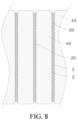
- the heat exchanger 20 is defined with a thickness D in the third direction, where D satisfies: 2 mm ⁇ D ⁇ 5 mm.
- D satisfies: 2 mm ⁇ D ⁇ 5 mm.
- D satisfies: 2 mm ⁇ D ⁇ 5 mm.
- D satisfies: 2 mm ⁇ D ⁇ 5 mm.
- D is less than 2 mm
- the thickness of the heat exchanger 20 is relatively small, so that the structural strength of the heat exchanger 20 is relatively low, and the heat exchanger 20 is prone to deformation during mounting and use to affect the heat dissipation efficiency of the battery pack to which the heat exchanger 20 is applied.
- D is greater than 5 mm, the thickness of the heat exchanger 20 is relatively large, so that a volume of the battery pack will be increased, and a volume utilization rate of the battery pack will be reduced.
- the thickness D of the heat exchanger 20 ranges from 2 mm to 5 mm, the structural strength of the heat exchanger 20 can be ensured, deformation of the heat exchanger 20 can be avoided, meanwhile, the heat dissipation efficiency of the battery pack can be ensured, and the volume utilization rate of the battery pack can be ensured.
- each second heat exchange flow channel 212 and each first heat exchange flow channel 211 extend along a straight line of the first direction A.
- the first heat exchange flow channel 211 and the second heat exchange flow channel 212 extend in the first direction A, and flow velocity of the heat exchange fluid used for exchanging heat inside the flow channels can be increased, so that the heat exchange fluid can reduce the heat on the second heat exchange section 21b more quickly to improve use safety of the heat exchanger 20.
- the heat exchanger 20 is formed by splicing the first heat exchange section 21a with the corresponding second heat exchange sections 21b.
- the first heat exchange section 21a and the second heat exchange section 21b may be respectively manufactured, and connecting surfaces of the second heat exchange section 21b and the first heat exchange section 21a may be welded together through a welding process, so that the first heat exchange flow channel 211 is communicated with the second heat exchange flow channel 212.
- a third confluence area 237 and a fourth confluence area 238 are respectively provided at ends of the two second heat exchange sections 21b away from the first heat exchange section 21a.
- the third confluence area 237 and the fourth confluence area 238 may be respectively defined by the ends of the two second heat exchange sections 21b away from each other.
- the third confluence area 237 and the fourth confluence area 238 are cavities with two open ends in the first direction A.
- One end of the third confluence area 237 and one end of the fourth confluence area 238 away from the second heat exchange sections 21b are communicated with an exterior.
- the third confluence area 237 and the fourth confluence area 238 are welded with the ends of the two second heat exchange sections 21b away from each other.
- the third confluence area 237 and the fourth confluence area 238 can reduce the flow velocity of the heat exchange fluid, meanwhile, can ensure sufficient flow rate of the heat exchange fluid entering the multiple second heat exchange flow channels 212, and improve the heat exchange efficiency.
- the heat exchange fluid flowing out of the second heat exchange flow channels 212 may converge first and then flow out, so that time of the heat exchange fluid in the heat exchange flow channels can be prolonged, and outflow velocity of the heat exchange fluid can be reduced.
- the heat exchange fluid entering the heat exchanger 20 may flow through the third confluence area 237, one second heat exchange flow channel 212, the first confluence area 235, the first heat exchange flow channel 211, the second confluence area 236, and the other second heat exchange flow channel 212 in sequence, and flows out from the fourth confluence area 238.
- first heat exchange section 21a and the corresponding second heat exchange sections 21b are spliced to form the heat exchanger 20, which can reduce difficulties in a manufacturing process of the heat exchanger 20 and improve assembly efficiency of the heat exchanger 20.
- the first heat exchange section 21a and the second heat exchange section 21b are respectively extrusion molding pieces.
- the first heat exchange section 21a and the second heat exchange section 21b are manufactured through an extrusion molding process, which can effectively reduce manufacturing costs of the heat exchanger 20, improve a utilization rate of materials for manufacturing the heat exchanger 20, and improve manufacturing efficiency and product yield.
- the second heat exchange flow channel 212 or the first heat exchange flow channel 211 inside the heat exchanger 20 may be spaced away in the second direction B of the heat exchanger 20 and may extend in the first direction A of the heat exchanger 20, thereby increasing heat exchange area and improving a heat exchange capability of the heat exchanger 20.
- a battery pack 1000 includes a cell unit 3 and at least one heat exchanger 20.
- the heat exchanger 20 is the heat exchanger 20 according to any embodiment of the foregoing aspect of the present disclosure.
- the cell unit 3 includes multiple cell groups 31.
- Each cell group 31 includes at least one cell 10.
- the heat exchanger 20 is configured to perform heat exchange on the cell 10.
- the battery pack 1000 includes multiple heat exchangers 20.
- the cell groups 31 are arranged alternately with the heat exchangers 20 in a third direction C of the heat exchanger 20.
- the third direction C is perpendicular to a first direction A.
- each cell group 31 including one cell 10 is taken as an example here, that is, the heat exchangers 20 being arranged on two sides of each cell 10 in the third direction C is taken as an example.
- the heat exchangers 20 and the cells 10 are arranged alternately in sequence in the third direction C of the heat exchanger 20.
- a quantity of first heat exchange flow channels 211 included in each heat exchanger 20 is less than that of second heat exchange flow channels 212, and a volume proportion of the second heat exchange flow channels 212 in each second heat exchange section 21b is greater than that of the first heat exchange flow channels 211 in a first heat exchange section 21a.
- the quantity of the first heat exchange flow channels 211 is relatively small, so that structural strength of the corresponding first heat exchange section 21a is higher than that of the second heat exchange section 21b.
- a central position of a large surface of the cell is a surface with the highest expansion probability and/or the highest expansion degree during use of the cell 10, so that the heat exchanger 20 can effectively suppress deformation of the cell 10 and prolong service life of the cell 10 when the cell 10 is deformed by heat.
- Flow directions of the heat exchange fluid inside the multiple heat exchangers 20 are the same, which can improve heat dissipation efficiency of the multiple cells 10.
- a distance between two adjacent heat exchangers 20 gradually increases from a center of the cell unit 3 to two ends of the cell unit 3 in the third direction.
- the distance between the two adjacent heat exchangers 20 gradually increasing from the center of the cell unit 3 to the two ends of the cell unit 3 in the third direction refers to that the distance between the two adjacent heat exchangers 20 is in an increasing trend from the center of the cell unit 3 to the two ends of the cell unit 3 in the third direction, for example, may increase regularly.
- the distance between the two adjacent heat exchangers 20 is in an increasing trend from the center of the cell unit 3 to the two ends of the cell unit 3 in the third direction, for example, may increase regularly. For example, in an example in FIG.
- the distance between the two adjacent heat exchangers 20 gradually increasing from the center of the cell unit 3 to the two ends of the cell unit 3 in the third direction may be that, from the center of the cell unit 3 to the two ends of the cell unit 3 in the third direction, a distance between a first cell group 31 and a second cell group 31 is less than that between the second cell group 31 and a third cell group 31, the distance between the second cell group 31 and the third cell group 31 is less than that between the third cell group 31 and a fourth cell group 31, and so on.
- the distance between two adjacent heat exchangers 20 may increase irregularly from the center of the cell unit 3 to the two ends of the cell unit 3 in the third direction.
- a distance between a first cell group 31 and a second cell group 31 is equal to that between the second cell group 31 and a third cell group 31, the distance between the second cell group 31 and the third cell group 31 is less than that between the third cell group 31 and a fourth cell group 31, the distance between the third cell group 31 and the fourth cell group 31 is less than that between the fourth cell group 31 and a fifth cell group 31, and so on.
- the cell 10 located in a central area of the battery pack 1000 in the third direction has a poor heat dissipation capability.
- the heat exchangers 20 and the cell groups 31 are arranged alternately, and the density of the heat exchangers 20 located in the middle of the third direction of the battery pack 1000 is set to be relatively large, so that the heat dissipation efficiency of the battery pack 1000 can be improved, a quantity of the heat exchangers 20 can be reduced and costs of the battery pack 1000 can be reduced while quickly reducing temperature of the battery pack 1000.
- a coolant may enter the heat exchanger 20 through a heat exchange fluid inlet and perform heat exchange with the cell 10 in the heat exchanger 20 to reduce the temperature of the cell 10, and the coolant after heat exchange flows out of the heat exchanger 20 through a heat exchange fluid outlet.
- heat dissipation of the cell 10 is achieved.
- the battery pack 1000 further includes a box body 1.
- the cell unit 3 is arranged in the box body 1.
- a shape of the box body 1 is roughly rectangular.
- a manufacturing material of the box body 1 may be metal materials such as aluminum alloy or steel, or may be a high strength composite material, so that the cell unit 3 in the box body 1 can be protected well.
- Four side walls that are connected to each other of the box body 1 define an accommodation cavity 301 together, and the cell unit 3 is arranged in the accommodation cavity 301.
- the cell 10 has a length direction, a width direction, and a thickness direction orthogonal to each other.
- a size of the cell 10 in the length direction is greater than or equal to those of the cell 10 in the width direction and the thickness direction.
- a size of the cell 10 in the width direction is greater than or equal to that of the cell 10 in the thickness direction.
- the thickness direction of the cell 10 is a third direction, the length direction of the cell 10 is a first direction, and the width direction of the cell 10 is a second direction.
- the battery pack 1000 further includes a tray 300 and a cover plate 200.
- the cell 10 and the heat exchanger 20 are placed in the accommodation cavity 301 defined by the tray 300.
- the cover plate 200 encloses the accommodation cavity 301.
- cold plates may be arranged on two sides of the second direction B of the heat exchanger 20 to increase heat dissipation of two side surfaces of the cell 10 in the second direction B.
- the battery pack 1000 includes the heat exchanger 20 according to any one of the foregoing embodiments, which can improve a heat dissipation capability of the battery pack 1000 and improve use safety of the battery pack 1000.
- the battery pack 1000 may be applied to a vehicle.
- the battery pack 100 being applied to the vehicle is taken as an example for description.
- the heat exchangers 20 are arranged in the third direction C.
- Each heat exchanger 20 is provided with an inlet 233 and an outlet 234 in two ends in the first direction A.
- the inlet 233 is a heat exchange fluid inlet of the heat exchanger 20
- the outlet 234 is a heat exchange fluid outlet of the heat exchanger 20.
- the inlet 233 may be provided on one of the third confluence area 237 and the fourth confluence area 238, and the outlet 234 may be provided on the other of the third confluence area 237 and the fourth confluence area 238.
- the inlets 233 of the multiple heat exchangers 20 are located at the same end of the heat exchangers 20 in the first direction A and are communicated with one another, and the outlets 234 of the multiple heat exchangers 20 are located at the other end of the heat exchangers 20 in the first direction A and are communicated with one another.
- two adjacent inlets 233 and two adjacent outlets 234 are respectively communicated with each other through connecting pipes 35.
- the connecting pipe 35 at the inlet 233 may be referred to as a fluid input pipe 33
- the connecting pipe 35 at the outlet 234 may be referred to as a fluid output pipe 34.
- a quantity of the fluid input pipe 33 is greater than or equal to 1, and a quantity of the fluid output pipe 34 is greater than or equal to 1.
- the heat exchanger 20 is communicated with both the fluid input pipe 33 and the fluid output pipe 34. Specifically, the fluid input pipe 33 of the heat exchanger 20 is communicated with the heat exchange fluid inlet, and the fluid output pipe 34 of the heat exchanger 20 is communicated with the heat exchange fluid outlet.
- the battery pack 1000 When the battery pack 1000 is charged, the cell 10 generates heat.
- a coolant flows into the heat exchange fluid inlet through the fluid input pipe 33 and enters the heat exchanger 20.
- the coolant flows through an end portion and a middle of a cooling flow channel, and performs heat exchange with the heat generated by the cell 10 in the heat exchange flow channel to reduce the temperature of the cell 10.
- the coolant after heat exchange flows out from the heat exchange fluid outlet, and flows out of the heat exchanger 20 through the fluid output pipe 34.
- the heat exchanger 20 is connected to an adjacent heat exchanger 20 through the fluid input pipe 33 and the fluid output pipe 34, so that the coolant can enter the multiple heat exchangers 20 through the heat exchange fluid inlets, and finally flows into a coolant storage device through the fluid output pipe 34.
- a complete heat exchange cycle is completed to dissipate heat of the cell 10.
- the cell 1000 includes a connecting inlet pipe 36 and a connecting outlet pipe 37.
- the connecting inlet pipe 36 is connected to the inlet 233 of the heat exchanger 20, and the connecting outlet pipe 37 is connected to the outlet 234 of the heat exchanger 20, so that the heat exchanger 20 can be communicated with an external system.
- the fluid input pipe 33 and the fluid output pipe 34 on the heat exchanger 20 located on the outermost side may be communicated with the coolant storage device through the connecting inlet pipe 36 and the connecting outlet pipe 37 respectively.
- High-temperature heat exchange fluid flowing out from the connecting outlet pipe 37 may form low-temperature heat exchange fluid through the external system and flows into the heat exchanger 20 from the connecting inlet pipe 36 to perform heat dissipation on the cell 10.
- Flow directions of the heat exchange fluid inside the multiple heat exchangers 20 are the same, for example, flowing from a left side to a right side shown in FIG. 5 in the first direction A of the heat exchanger 20.
- the flow directions of the heat exchange fluid inside the multiple heat exchangers 20 are not limited here, and the heat exchange fluid may alternatively flow from right to left.
- each heat exchanger 20 is provided with an inlet 233 and an outlet 234.
- the multiple inlets 233 are communicated with one another.
- the multiple outlets 234 are communicated with one another.
- the heat exchange fluid entering interiors of the heat exchangers 20 may enter from the inlets 233 of the multiple heat exchangers 20 and flow out from the outlets 234 of the multiple heat exchangers 20 to achieve synchronous heat dissipation of the multiple cells 10 and improve the heat dissipation efficiency of the cells 10.
- the battery pack 1000 further includes: a heat conducting piece 5.
- the heat conducting piece 5 is arranged between the heat exchanger 20 and the cell group 31. In the third direction C of the heat exchanger 20, heat exchangers 20 are arranged on two sides of the cell 10, and the heat conducting piece 5 may be arranged between the heat exchanger 20 and the cell 10 to facilitate transferring the heat generated by the cell 10 to the heat exchanger 20.
- the heat conducting piece 5 may be coated or filled between the heat exchanger 20 and the cell 10.
- the heat conducting piece 5 is a heat conductive structure adhesive, heat conductive silicone, or heat conductive silicone grease, but is not limited to this, as long as a material for manufacturing the heat conducting piece 5 is a high temperature resistant insulation material.
- the heat conducting piece 5 may have binding property to facilitate mounting between the cell 10 and the heat exchanger 20 while dissipating the heat of the cell 10 that is in contact with the heat conducting piece 5.
- the heat conducting piece 5 further has insulating property and high temperature resistance, and the heat conducting piece 5 has good heat conducting property, which can improve the heat dissipation capability of the cell 10 and improve structural strength and stability of the battery pack 1000.
- the heat conducting piece 5 is arranged between the heat exchanger 20 and the cell group 31, which may increase heat conductivity between the cell 10 and the heat exchanger 20, so that the heat on the cell 10 can be transferred to the heat exchanger 20 as much as possible to improve the heat exchange capability of the heat exchanger 20 through the heat conducting piece 5. Therefore, the heat dissipation efficiency of the cell 10 can be improved, good performance of the cell 10 can be maintained, and the heat dissipation efficiency of the battery pack 1000 can be further improved.
- a surface of the heat exchanger 20 is provided with an insulation layer.
- the insulation layer may form an insulation film in insulation treatment manners such as spraying, electrophoresis, or coating an insulation film.
- An arrangement of the insulation layer can prevent a current from being transferred to the heat exchanger 20 when the cell 10 leaks electricity.
- the heat exchanger 20 may be a harmonica-shaped pipe, a stamping and brazing cold plate, or cold plates in other forms.
- the heat exchanger 20 may be an aluminum alloy piece.
- the cell 10 may be a rechargeable secondary cell, for example, a lithium iron phosphate cell or a ternary material cell. Terminals of the cell 10 may be led out from a first direction of the cell 10, or led out from a second direction of the cell 10. That is, the terminals may be arranged on the same side or different sides of the cell 10.
- the battery pack 1000 further includes fireproof pieces.
- the fireproof pieces are arranged on at least parts of two opposite side surfaces of the cell group 31 in the first direction and two opposite side surfaces in the second direction.
- the fireproof piece may be arranged on a surface of the cell group 31 that is not in contact with the heat conducting piece 5 and the heat exchanger 20. The use of the fireproof piece can prevent danger such as catching fire of the battery pack 1000 due to over-high temperature and ensures use safety of the battery pack 1000.
- the first direction A is a length direction of the cell 10
- the second direction B is a width direction of the cell 10
- the third direction A is a thickness direction of the cell 10
- the third direction C, the second direction B, and the first direction A are orthogonal to each other.
- a size of the cell 10 in the length direction is defined as L
- a size of the cell 10 in the width direction is defined as W
- a size of the cell 10 in the thickness direction is defined as D
- L, W, and D satisfy: L ⁇ W ⁇ D.
- the multiple cell groups 31 are arranged in the third direction C.
- the multiple heat exchangers 20 include a first heat exchanger 21 and a second heat exchanger 22.
- the first heat exchanger 21 is provided with a first heat exchange inlet 216 and a first heat exchange outlet 213.
- the second heat exchanger 22 is provided with a second heat exchange inlet 222 and a second heat exchange outlet 223.
- the cell group 31 has a third direction C and a first direction A perpendicular to each other.
- the first heat exchanger 21 and the second heat exchanger 22 are arranged in the third direction C.
- the first heat exchange inlet 216 and the second heat exchange outlet 223 are located at one end of the heat exchanger 20 in the first direction A, and the first heat exchange outlet 213 and the second heat exchange inlet 222 are located at the other end of the heat exchanger 20 in the first direction A.
- the first heat exchanger 21 is arranged on one side of each cell group 31 in the third direction C, and the second heat exchanger 22 is arranged on the other side in the third direction C.
- each cell group 31 including one cell 10 is taken as an example.
- first heat exchanger 21 and second heat exchanger 22 are spaced away from each other.
- the first heat exchanger 21 and the second heat exchanger 22 may operate independently.
- the first heat exchanger 21 and the second heat exchanger 22 are respectively arranged on two sides of the cell 10 in the third direction C.
- the first heat exchange inlet 216 and the second heat exchange inlet 222 are respectively located at the two ends of the heat exchanger 20 in the third direction C, so heat exchange fluid may enter the first heat exchanger 21 and the second heat exchanger 22 from different directions.
- the heat exchange fluid enters a heat exchange flow channel from the second heat exchange inlet 222.
- a portion of the cell 10 adjacent to the second heat exchange inlet 222 dissipates heat quickly, and a portion away from the second heat exchange inlet 222 dissipates heat slowly.
- the heat exchange fluid takes away heat of the portion of the cell 10 adjacent to the second heat exchange inlet 222 to cause a temperature rise of the heat exchange fluid
- temperature difference between the heat exchange fluid and the portion of the cell 10 away from the second heat exchange inlet 222 is reduced, and the heat of the portion of the cell 10 adjacent to the second heat exchange inlet 222 taken away by the heat exchange fluid is limited, so that a heat dissipation effect of the portion of the cell 10 adjacent to the second heat exchange inlet 222 is poor. Therefore, different positions of the cell 10 have different heat dissipation effects.
- the heat exchange fluid flowing into the heat exchanger 20 from the first heat exchange inlet 212 located on the other side may take away the heat dissipated by the portion of the foregoing cell 10 with a poor heat dissipation effect, so that heat dissipation capabilities of the two ends of the cell 10 in the first direction A are the same, and an impact of the heat absorbed by the heat exchange fluid during flowing on the heat dissipation effect is reduced.
- the first heat exchanger 21 and the second heat exchanger 22 are respectively arranged on two opposite sides of the cell 10 in the third direction, and inlets of the first heat exchanger 21 and the second heat exchanger 22 are respectively located at two ends in the first direction A, so as to facilitate entering of the heat exchange fluid from the two ends in the first direction A to the first heat exchanger 21 and the second heat exchanger 22 to perform synchronous heat dissipation on the two ends of the cell 10 in the first direction A and the two sides in the third direction C and improve the heat dissipation efficiency of the cell 10, thereby achieving balanced heat dissipation of the cell 10 in the third direction C and improving the heat dissipation capability of a battery device 100.
- the first heat exchanger 21 is not communicated with the second heat exchanger 22.
- the heat dissipation efficiency of two ends of the cell 10 in the first direction A can be improved.
- a flow direction of heat exchange fluid in the first heat exchanger 21 is opposite to that of heat exchange fluid in the second heat exchanger 22.
- the heat exchange fluid inside the second heat exchanger 22 may flow from left to right, and the heat exchange fluid inside the first heat exchanger 21 may flow from right to left.
- flow directions of the heat exchange fluid in the first heat exchanger 21 and the second heat exchanger 22 are opposite.
- Heat dissipation velocity of the cell 10 on the two sides of the cell 10 can be increased, and uneven heat dissipation of the two ends of the cell 10 in the third direction C caused by a fact that the heat exchange fluid on the two sides of the cell 10 flow in the same direction can be avoided, so that possibility of thermal expansion of a portion of the cell 10 caused by the uneven heat dissipation can be reduced, the battery device 100 has a more efficient heat dissipation capability, and use safety and use reliability of the battery device 100 are improved.
- each first heat exchanger 21 extends in the first direction A, and each first heat exchanger 21 is internally provided with a first heat exchange flow channel 211 and a second heat exchange flow channel 212 extending in the first direction A.
- Each second heat exchanger 22 extends in the first direction A, and each second heat exchanger 22 is internally provided with a first heat exchange flow channel 211 and a second heat exchange flow channel 212 extending in the first direction A.
- first heat exchange flow channels 211 and the second heat exchange flow channels 212 are provided in the first heat exchanger 21 and the second heat exchanger 22, which can facilitate flowing of the heat exchange fluid in the heat exchange flow channels to take away the heat of the cell 10 transferred to the heat exchanger, so as to achieve heat dissipation of the cell 10 and ensure the use safety of the battery device 100.
- multiple first heat exchange flow channels 211 are provided.
- the multiple first heat exchange flow channels 211 are spaced away in the second direction B.
- Multiple second heat exchange flow channels 212 are provided.
- the multiple second heat exchange flow channels 212 are spaced away in the second direction B.
- the multiple first heat exchange flow channels 211 and the multiple second heat exchange flow channels 212 are provided, and the multiple first heat exchange flow channels 211 and the multiple second heat exchange flow channels 212 are respectively spaced away in the second direction B, so that flow area of the heat exchange fluid in the first heat exchange flow channels 211 and the second heat exchange flow channels 212 can be increased, flow velocity of the heat exchange fluid in the first heat exchange flow channels 211 and the second heat exchange flow channels 212 can be reduced, and flow time of the heat exchange fluid in the heat exchange flow channels can be prolonged, which facilitates taking away the heat dissipated by the cell 10 by the heat exchange fluid and reducing the temperature of the cell 10.
- a volume proportion of the multiple first heat exchange flow channels 211 in the first heat exchange section 21a is less than that of the multiple second heat exchange flow channels 212 in the second heat exchange section 21b.
- a volume proportion of the multiple first heat exchange flow channels 211 in the first heat exchange section 21a is less than that of the multiple second heat exchange flow channels 212 in the second heat exchange section 21b.
- a ratio of a total volume of the multiple first heat exchange flow channels 211 in the first heat exchange section 21a to a volume of the first heat exchange section 21a is less than that of a total volume of all second heat exchange flow channels 212 in the second heat exchange section 21b to a volume of the second heat exchange section 21b.
- a ratio of a total volume of the multiple first heat exchange flow channels 211 in the first heat exchange section 21a to a volume of the first heat exchange section 21a is less than that of a total volume of all second heat exchange flow channels 212 in the second heat exchange section 21b to a volume of the second heat exchange section 21b.
- a total flow rate of the first heat exchange flow channels 211 in the first heat exchange section 21a is less than that of the second heat exchange flow channels 212 in the second heat exchange section 21b.
- the two second heat exchange sections 21b arranged at the end portions of the heat exchanger 20 are respectively arranged adjacent to the two terminals at the two ends of the cell 10, thereby improving the heat dissipation efficiency near the terminals at the two ends of the cell 10 purposefully.
- respective first heat exchange sections 21a of the first heat exchanger 21 and the second heat exchanger 22 are lower than those of respective second heat exchange section 21b of the first heat exchanger 21 and the second heat exchanger 22, so that the two ends of the heat exchanger 20 in the first direction A have a good heat dissipation effect near the terminals of the cell 10.
- structural strength of the first heat exchange section 21a is higher than that of at least one second heat exchange section 21b.
- structural strength of the first heat exchange section 21a is higher than that of at least one second heat exchange section 21b.
- first heat exchanger 21 and the second heat exchanger 22 when a hole diameter of the first heat exchange flow channel 211 is the same as that of the second heat exchange flow channel 212, relatively few first heat exchange flow channels 211 are provided in the first heat exchange section 21a, so that a ratio of a sum of the volumes of the multiple first heat exchange flow channels 211 to the volume of the first heat exchange section 21a is reduced, and the structural strength of the first heat exchange section 21a can be relatively improved.
- the structural strength of the first heat exchange section 21a is higher than that of the second heat exchange section 21b, so that the first heat exchange section 21a has good deformation resistance.
- a central position of the large surface of the cell is a surface with the highest expansion probability and/or the highest expansion degree during use of the cell 10, so that the structural strength of the first heat exchange section 21a located in the middle of the heat exchanger 20 is higher than that of the second heat exchange section 21b at an end portion, expansion of the cell 10 can be suppressed, and stability of the cell 10 and the heat exchanger 20 can be improved.
- a wall thickness of the first heat exchange flow channel 211 of the at least one first heat exchange section 21a is greater than that of the second heat exchange flow channel 212 of the at least one second heat exchange section 21b. That is, in the first heat exchanger 21 and the second heat exchanger 22, the wall thickness of each first heat exchange flow channel 211 corresponding to the first heat exchange section 21a is greater than that of each second heat exchange flow channel 212 corresponding to the second heat exchange section 21b.
- the flow rate of the heat exchange fluid flowing through the first heat exchange section 21a may be reduced by reducing the quantity of the first heat exchange flow channels 211 in the first heat exchange section 21a, and a wall thickness between two adjacent first heat exchange flow channels 211 in the first heat exchange section 21a may be increased by increasing a distance between an inner side surface of the first heat exchange flow channel 211 and an outer surface of the cell 10 in the third direction C.
- the wall thickness of the first heat exchange flow channel 211 corresponding to the first heat exchange section 21a is greater than that of the second heat exchange flow channel 212 corresponding to the second heat exchange section 21b, which can improve the structural strength of the first heat exchange section 21a.
- the first heat exchanger 21 and the second heat exchanger 22 may better suppress deformation of the cell 10 in the third direction C and enhance protection of the cell 10.
- multiple heat exchangers 20 include multiple first heat exchangers 21 and multiple second heat exchangers 22.
- the battery pack 1000 further includes a first connecting pipe 23 (for example, as shown in FIG. 13 , multiple first connecting pipes 23), a second connecting pipe 24 (for example, as shown in FIG. 13 , multiple second connecting pipes 24), a third connecting pipe 25 (for example, as shown in FIG. 13 , multiple third connecting pipes 25), and a fourth connecting pipe 26 (for example, as shown in FIG. 13 , multiple fourth connecting pipes 26).
- each first connecting pipe 23 is connected between the first heat exchange inlets 216 of two adjacent first heat exchangers 21, and each second connecting pipe 24 is connected between the first heat exchange outlets 213 of the two adjacent first heat exchangers 21.
- Each third connecting pipe 25 is connected between the second heat exchange inlets 222 of two adjacent second heat exchangers 22, and each fourth connecting pipe 26 is connected between the second heat exchange outlets 223 of the two adjacent second heat exchangers 22.
- the multiple first heat exchangers 21 and the multiple second heat exchangers 22 are spaced away from one another in the third direction C.
- Each first heat exchanger 21 is provided with a first heat exchange inlet 216 and a first heat exchange outlet 213.
- Each second heat exchanger 22 is provided with a second heat exchange inlet 222 and a second heat exchange outlet 223.
- Two adjacent first heat exchange inlets 216 are connected to each other through the first connecting pipe 23.
- Two adjacent first heat exchange outlets 213 are connected to each other through the second connecting pipe 24.
- Two adjacent second heat exchange inlets 222 are connected to each other through the third connecting pipe 25.
- Two adjacent second heat exchange outlets 223 are connected to each other through the fourth connecting pipe 26. Therefore, the flow direction of the heat exchange fluid in the first heat exchanger 21 is opposite to that of the heat exchange fluid in the second heat exchanger 22 to perform heat dissipation on the cell 10 from the two ends of the cell 10.
- the two adjacent first heat exchangers 21 are communicated with each other, and the two adjacent second heat exchangers 22 are communicated with each other, so that the heat exchange fluid entering the heat exchanger 20 enters from different first heat exchange inlets 216 and second heat exchange inlets 222, the heat exchange efficiency of the heat exchanger 20 is improved, a temperature balance at the first heat exchange inlets 216 and the first heat exchange outlets 213 and a temperature balance at the second heat exchange inlets 222 and the second heat exchange outlets 223 are achieved, temperature consistency of the cell 10 can be improved, temperature difference between the two ends of the cell 10 in the length direction and the middle can be minimized, the cell 10 can be protected, and service life of the cell 10 can be prolonged to the greatest extent.
- the battery pack 1000 further includes a first heat exchanger inlet pipe 214, a second heat exchanger outlet pipe 215, a second heat exchanger inlet pipe 224, and a second heat exchanger outlet pipe 225.
- the first heat exchanger inlet pipe 214 is connected to the first heat exchange inlet 216 of the first heat exchanger 21 located on the outermost side in the third direction C
- the first heat exchanger outlet pipe 215 is connected to the first heat exchange outlet 213 of the first heat exchanger 21 located on the outermost side in the third direction C
- the first heat exchanger outlet pipe 215 and the first heat exchanger inlet pipe 214 are located on the same side in the third direction C.
- the second heat exchanger inlet pipe 224 is connected to the second heat exchange inlet 222 of the second heat exchanger 22 located on the outermost side in the third direction C
- the second heat exchanger outlet pipe 225 is connected to the second heat exchange outlet 223 of the second heat exchanger 22 located on the outermost side in the third direction C
- the second heat exchanger outlet pipe 225 and the second heat exchanger inlet pipe 224 are located on the other side in the third direction C.
- the first heat exchange inlet 216 and the first heat exchange outlet 213 of the first heat exchanger 21 located on the outermost side are respectively connected to the first heat exchanger inlet pipe 214 and the first heat exchanger outlet pipe 215, and the second heat exchange inlet 222 and the second heat exchange outlet 223 of the second heat exchanger 22 located on the outermost side are respectively connected to the second heat exchanger inlet pipe 224 and the second heat exchanger outlet pipe 225.
- the heat exchange fluid inside the multiple first heat exchangers 21 enters from the first heat exchanger inlet pipe 214 and flows out from the first heat exchanger outlet pipe 215, and the heat exchange fluid inside the multiple second heat exchangers 22 enters from the second heat exchanger inlet pipe 224 and flows out from the second heat exchanger outlet pipe 225.
- the heat exchanger 20 is communicated with an external system, the heat exchange fluid used for cooling is injected, and the heat exchange fluid can flow out smoothly after flowing through the heat exchanger 20 to absorb the heat of the cell 10.
- the first heat exchanger inlet pipe 214 and the first heat exchanger outlet pipe 215 are arranged on one side of the cell 10, and the second heat exchanger inlet pipe 224 and the second heat exchanger outlet pipe 225 are arranged on the other side of the cell 10, which facilitates arranging the first heat exchanger 21 and the second heat exchanger 22, reducing space occupied by the external system connected to the first heat exchanger inlet pipe 214 and the first heat exchanger outlet pipe 215, and improving a utilization rate of the space in the battery pack 1000.
- each first connecting pipe 23, each second connecting pipe 24, each third connecting pipe 25, and each fourth connecting pipe 26 are respectively corrugated pipes.
- a corrugated pipe is a tubular elastic sensitive element formed by connecting foldable corrugated pieces in folding, stretching, and retracting directions.
- materials of the first connecting pipe 23 to the fourth connecting pipe 26 may be metal, and shapes of the connecting pipes may be U-shaped.
- the first connecting pipe 23 to the fourth connecting pipe 26 use the corrugated pipes, so that elasticity of the connecting pipes can be increased, the first connecting pipe 23 to the fourth connecting pipe 26 have good deformation capabilities, and adjustment of the connecting pipe is facilitated.
- the first heat exchanger 21 is defined with a thickness L1
- the second heat exchanger 22 is defined with a thickness L2
- L1 and L2 satisfy: 2 mm ⁇ L1 ⁇ 5 mm, and 2 mm ⁇ L2 ⁇ 5 mm.
- L1 2.5 mm
- L2 2.5 mm.
- a thickness of the heat exchanger 20 is relatively small by defining the thicknesses of the first heat exchanger 21 and the second heat exchanger 22.
- the occupation of internal space of the battery pack 1000 can be effectively reduced when the heat exchanger 20 is placed between adjacent cells 10, which facilitates a miniaturized design of the battery pack 1000. Meanwhile, problems that the structural strength of the first heat exchanger 21 and the second heat exchanger 22 cannot be ensured and the heat dissipation capabilities are weak due to small thicknesses of the first heat exchanger 21 and the second heat exchanger 22 can be avoided.
- a first heat conducting piece 51 is arranged between the first heat exchanger 21 and the cell 10
- a second heat conducting piece 52 is arranged between the second heat exchanger 22 and the cell 10.
- the first heat conducting piece 51 and the second heat conducting piece 52 are respectively heat conductive structure adhesives, heat conductive silicone, or heat conductive silicone grease.
- the first heat conducting piece 51 and the second heat conducting piece 52 facilitate mounting between the cell 10 and the first heat exchanger 21 and between the cell 10 and the second heat exchanger 22 while dissipating the heat of the cell 10 that is in contact with the first heat conducting piece 51 and the second heat conducting piece 52.
- the first heat conducting piece 51 and the second heat conducting piece 52 further have insulating property and high temperature resistance.
- the first heat conducting piece 51 and the second heat conducting piece 52 use the heat conductive structure adhesive and the like, so that the heat conducting pieces have good heat conductivity, the heat dissipation capability of the cell 10 can be improved, structural strength and stability of the battery pack 1000 can be improved.
- multiple cell groups 31 are spaced away from one another in the third direction C.
- One of the first heat exchanger 21 and the second heat exchanger 22 is arranged on one side of each cell group 31 in the third direction C, and the other of the first heat exchanger 21 and the second heat exchanger 22 is arranged on the other side of each cell group 31 in the third direction C.
- Flow directions of the heat exchange fluid inside the first heat exchanger 21 and the second heat exchanger 22 are opposite to simultaneously perform heat dissipation on the cell 10 in two ends of the first direction A.
- a vehicle 2000 according to an embodiment in a third aspect of the present disclosure includes the battery pack 1000 according to the embodiments in the second aspect.
- the vehicle according to the embodiments of the present disclosure includes the battery pack 1000 according to any of the foregoing embodiments.
- the heat dissipation capability and the heat dissipation efficiency of the battery pack 1000 are improved, normal operation of the battery pack 1000 is ensured, possibility of safety accidents such as explosions caused by a weak heat dissipation capability of the battery pack is reduced, an endurance capability of the vehicle is improved, service life of the vehicle is prolonged, and use costs and maintenance costs of the vehicle are reduced.
- orientation or position relationships indicated by terms such as “center”, “longitudinal”, “transverse”, “length”, “width”, “thickness”, “upper”, “lower”, “front”, “rear”, “left”, “right”, “vertical”, “horizontal”, “top”, “bottom”, “inner”, “outer”, “axial”, “radial”, and “circumferential” are based on orientation or position relationships shown in accompanying drawings, and are used only for describing the present disclosure and simplifying a description rather than indicating or implying that a referred device or element has to have a particular orientation or has to be constructed and operated in a particular orientation. Therefore, such terms cannot be construed as a limitation to the present disclosure.
- a first feature or “a second feature” may include one or more of the features.
- “multiple” means two or more.
- a first feature is “on” or “below” a second feature may include that the first and second features are in direct contact, or may include that the first and second features are not in direct contact but in contact through additional features between the first feature and the second feature.
- a first feature is "on”, “above”, or “over” a second feature includes that the first feature is right above and on the inclined top of the second feature or merely indicates that a level of the first feature is higher than that of the second feature.
Landscapes
- Engineering & Computer Science (AREA)
- Manufacturing & Machinery (AREA)
- Chemical & Material Sciences (AREA)
- Chemical Kinetics & Catalysis (AREA)
- Electrochemistry (AREA)
- General Chemical & Material Sciences (AREA)
- Secondary Cells (AREA)
- Cooling, Air Intake And Gas Exhaust, And Fuel Tank Arrangements In Propulsion Units (AREA)
Abstract
Description
- This application claims priority to and benefits of
Chinese Patent Application No. "202222010868.2" on July 29, 2022 Chinese Patent Application No. "202222002100.0" filed on July 29, 2022 Chinese Patent Application No. "202222011268.8" filed on July 29, 2022 - The present disclosure relates to the technical field of batteries, and in particular, to a heat exchanger, a battery pack, and a vehicle.
- In a related art, cells in a battery pack often have problems of low heat dissipation efficiency and uneven heat dissipation between different parts. Low heat dissipation efficiency or different heat dissipation degrees between the cells will lead to thermal expansion of some cells, which can limit an overall fast charging capability of the battery pack. A high-rate fast charging current strategy needs to be set in combination with temperature of the cells. Over-high local temperature of the cells will limit settings of the fast-charging policy to limit an overall fast charging capability. However, in the related art, a cooling device of the battery pack cannot effectively dissipate heat of a main heat generating area of the battery pack, cannot ensure evenness of the temperature of the battery pack, and causes local overheating easily.
- The present disclosure aims to solve at least one of technical problems in a related art. Therefore, a first objective of the present disclosure is to provide a heat exchanger, which has a good heat exchange capability.
- A second objective of the present disclosure is to provide a battery pack, including the foregoing heat exchanger and a cell.
- A third objective of the present disclosure is to provide a vehicle, including the foregoing battery pack.
- The heat exchanger according to an embodiment in a first aspect of the present disclosure includes a first heat exchange section and two second heat exchange sections. The two second heat exchange sections are respectively connected to two ends of the first heat exchange section in a first direction. The first heat exchange section is provided with at least one first heat exchange flow channel. The second heat exchange section is provided with at least one second heat exchange flow channel. A volume proportion of the second heat exchange flow channel in the at least one second heat exchange section is greater than that of the first heat exchange flow channel in the first heat exchange section.
- In the heat exchanger according to the present disclosure, the volume proportion of the second heat exchange flow channel in the at least one second heat exchange section is greater than that of the first heat exchange flow channel in the first heat exchange section, a heat exchange capability of the second heat exchange section is higher than that of the first heat exchange section, and heat exchange of the second heat exchange section is increased to facilitate improving heat dissipation efficiency of an end portion of a cell purposefully.
- In some embodiments, the volume proportion of the second heat exchange flow channel in each second heat exchange section is greater than that of the first heat exchange flow channel in the first heat exchange section.
- In some embodiments, multiple first heat exchange flow channels are provided, multiple second heat exchange flow channels are provided, and a quantity of the first heat exchange flow channels is less than that of the second heat exchange flow channels of the at least one second heat exchange section.
- In some embodiments, multiple first heat exchange flow channels are provided, and multiple second heat exchange flow channels are provided. The multiple first heat exchange flow channels are arranged in a second direction. The multiple second heat exchange flow channels are arranged in the second direction. The second direction is perpendicular to the first direction.
- In some embodiments, structural strength of the first heat exchange section is higher than that of the at least one second heat exchange section.
- In some embodiments, a portion of the first heat exchange section corresponding to the at least one second heat exchange flow channel is of a solid structure.
- In some embodiments, a wall thickness of the at least one first heat exchange flow channel is greater than that of the at least one second heat exchange flow channel.
- In some embodiments, each second heat exchange flow channel and each first heat exchange flow channel extend along a straight line of the first direction.
- In some embodiments, each first heat exchange section is spliced with the corresponding second heat exchange sections.
- In some embodiments, the first heat exchange section and each second heat exchange section are respectively extrusion molding pieces.
- The battery pack according to an embodiment in a second aspect of the present disclosure includes a cell and a heat exchanger. The heat exchanger is the heat exchanger according to the foregoing embodiments. The heat exchanger is configured to perform heat exchange on the cell.
- In some embodiments, the battery pack includes a cell unit. The cell unit includes multiple cell groups. Each cell group includes at least one cell. The battery pack includes multiple heat exchangers. The cell groups are arranged alternately with the heat exchangers in a third direction. The third direction is perpendicular to a first direction.
- In some embodiments, a distance between two adjacent heat exchangers gradually increases from a center of the cell unit to two ends of the cell unit in the third direction.
- In some embodiments, the multiple heat exchangers include a first heat exchanger and a second heat exchanger. The first heat exchanger is provided with a first heat exchange inlet and a first heat exchange outlet. The second heat exchanger is provided with a second heat exchange inlet and a second heat exchange outlet. The cell group has the first direction and the third direction perpendicular to each other. The first heat exchanger and the second heat exchanger are arranged in the third direction. The first heat exchange inlet and the second heat exchange outlet are located at one end of the heat exchanger in the first direction, and the first heat exchange outlet and the second heat exchange inlet are located at the other end of the heat exchanger in the first direction. The first heat exchanger is arranged on one side of the cell group in the third direction, and the second heat exchanger is arranged on the other side of the cell group in the third direction.
- In some embodiments, a flow direction of heat exchange fluid in the first heat exchanger is opposite to that of heat exchange fluid in the second heat exchanger.
- In some embodiments, the multiple heat exchangers include multiple first heat exchangers and multiple second heat exchangers. The battery pack further includes a first connecting pipe, where the first connecting pipe is connected between the first heat exchange inlets of two adjacent first heat exchangers; a second connecting pipe, where the second connecting pipe is connected between the first heat exchange outlets of the two adjacent first heat exchangers;
a third connecting pipe, where the third connecting pipe is connected between the second heat exchange inlets of two adjacent second heat exchangers; and a fourth connecting pipe, where the fourth connecting pipe is connected between the second heat exchange outlets of the two adjacent second heat exchangers. - In some embodiments, the battery pack further includes: a first heat exchanger inlet pipe, where the first heat exchanger inlet pipe is connected to the first heat exchange inlet of the first heat exchanger located on the outermost side in the third direction; a first heat exchanger outlet pipe, where the first heat exchanger outlet pipe is connected to the first heat exchange outlet of the first heat exchanger located on the outermost side in the third direction, and the first heat exchanger outlet pipe and the first heat exchanger inlet pipe are located on the same side in the third direction; a second heat exchanger inlet pipe, where the second heat exchanger inlet pipe is connected to the second heat exchange inlet of the second heat exchanger located on the outermost side in the third direction; and a second heat exchanger outlet pipe, where the second heat exchanger outlet pipe is connected to the second heat exchange outlet of the second heat exchanger located on the outermost side in the third direction, and the second heat exchanger outlet pipe and the second heat exchanger inlet pipe are located on the other side in the third direction.
- In some embodiments, the first heat exchanger is defined with a thickness L1, the second heat exchanger is defined with a thickness L2, and L1 and L2 satisfy: 2 mm≤L1≤5 mm, and 2 mm≤L2≤5 mm.
- In some embodiments, the multiple heat exchangers are arranged in the third direction. Each heat exchanger is provided with an inlet and an outlet in two ends in the first direction. The inlets of the multiple heat exchangers are located at the same end of the first direction and are communicated with one another, and the outlets of the multiple heat exchangers are located at the other end of the first direction and are communicated with one another.
- In some embodiments, the battery pack further includes multiple connecting pipes. A connecting pipe of the multiple connecting pipes located at the inlet is a fluid input pipe. A connecting pipe of the multiple connecting pipes located at the outlet is a fluid output pipe. The heat exchangers are communicated with both the fluid input pipe and the fluid output pipe.
- In some embodiments, the battery pack further includes: a heat conducting piece. The heat conducting piece is arranged between the heat exchanger and the cell group.
- A vehicle according to an embodiment in a third aspect of the present disclosure includes the battery pack according to the embodiments in the second aspect.
- Additional aspects and advantages of the present disclosure will be partially provided in the following descriptions, and some of which will become apparent from the following descriptions or may be learned from practices of the present disclosure.
- The foregoing and/or additional aspects and advantages of the present disclosure will become apparent and readily comprehensible from the following descriptions of the embodiments with reference to the accompanying drawings, where:
-
FIG. 1 is a schematic diagram of a battery pack according to some embodiments of the present disclosure; -
FIG. 2 is a schematic diagram of a heat exchanger and a cell unit according to some embodiments of the present disclosure; -
FIG. 3 is a partial three-dimensional split diagram of a heat exchanger and a cell unit according to some embodiments of the present disclosure; -
FIG. 4 is a schematic diagram of part cells and part heat exchangers according to some embodiments of the present disclosure; -
FIG. 5 is a schematic diagram of flowing of heat exchange fluid in a heat exchanger according to some embodiments of the present disclosure; -
FIG. 6 is a schematic diagram of distribution of heat exchange flow channels inside a heat exchanger according to some embodiments of the present disclosure; -
FIG. 7 is a cross-sectional schematic diagram of a heat exchanger according to some embodiments of the present disclosure; -
FIG. 8 is a cross-sectional schematic diagram of a heat exchanger and a cell according to some embodiments of the present disclosure; -
FIG. 9 is a schematic diagram of a battery pack according to some other embodiments of the present disclosure; -
FIG. 10 is a schematic diagram of a heat exchanger and a cell unit according to some other embodiments of the present disclosure; -
FIG. 11 is a schematic diagram of a heat exchanger and a cell unit according to still some embodiments of the present disclosure; -
FIG. 12 is a schematic diagram of a battery pack according to still some embodiments of the present disclosure; -
FIG. 13 is a partial schematic diagram of a battery pack according to still some embodiments of the present disclosure; -
FIG. 14 is a left view of a structure shown inFIG. 13 ; -
FIG. 15 is a schematic diagram of part heat exchangers and cells according to some embodiments of the present disclosure; -
FIG. 16 is a cross-sectional schematic diagram of part heat exchangers and cells according to some embodiments of the present disclosure; -
FIG. 17 is a cross-sectional schematic diagram of a first heat exchanger or a second heat exchanger according to some embodiments of the present disclosure; -
FIG. 18 is a schematic diagram of distribution of first heat exchange flow channels and second heat exchange flow channels in a first heat exchanger according to some embodiments of the present disclosure; -
FIG. 19 is a schematic diagram of distribution of first heat exchange flow channels and second heat exchange flow channels in a second heat exchanger according to some embodiments of the present disclosure; and -
FIG. 20 is a schematic block diagram of a vehicle according to an embodiment of the present disclosure. - In the drawings:
-
battery pack 1000;cell 10;heat exchanger 20; firstheat exchange section 21a; secondheat exchange section 21b; first heatexchange flow channel 211; - second heat
exchange flow channel 212;inlet 233;outlet 234;first confluence area 235;second confluence area 236;third confluence area 237; -
fourth confluence area 238;heat conducting piece 5; connectinginlet pipe 36; connectingoutlet pipe 37; connectingpipe 35;cover plate 200;tray 300; -
accommodation cavity 301; first direction A; second direction B; third direction C;box body 1;cell unit 3;cell group 31;fluid input pipe 33;fluid output pipe 34;heat conducting piece 5;first heat exchanger 21; first heatexchange flow channel 211; firstheat exchange inlet 216; firstheat exchange outlet 213; first heatexchanger inlet pipe 214; first heatexchanger outlet pipe 215;second heat exchanger 22; second heatexchange flow channel 212; secondheat exchange inlet 222; secondheat exchange outlet 223; second heatexchanger inlet pipe 224; second heatexchanger outlet pipe 225; first connectingpipe 23; second connectingpipe 24; third connectingpipe 25; fourth connectingpipe 26; firstheat conducting piece 51; secondheat conducting piece 52; andvehicle 2000. - Embodiments of the present disclosure are described in detail below, and the embodiments described with reference to accompanying drawings are exemplary.
- A
heat exchanger 20 according to an embodiment of the present disclose will be described below with reference toFIG. 1 to FIG. 20 . Theheat exchanger 20 includes a firstheat exchange section 21a and two secondheat exchange sections 21b. In some embodiments, a first direction A is a length direction of theheat exchanger 20, a second direction B is a width direction of theheat exchanger 20, a third direction C is a thickness direction of theheat exchanger 20, and the first direction A, the second direction B, and the third direction C are orthogonal to each other. A size of theheat exchanger 20 in the length direction is greater than or equal to that in the width direction. A size of theheat exchanger 20 in the width direction is greater than or equal to that in the thickness direction. - Specifically, as shown in
FIG. 2 ,FIG. 6 ,FIG. 18 , andFIG. 19 , the two secondheat exchange sections 21b of theheat exchanger 20 are respectively connected to two ends of the firstheat exchange section 21a in the first direction A of theheat exchanger 20. The firstheat exchange section 21a is provided with at least one first heatexchange flow channel 211. The secondheat exchange section 21b is provided with at least one second heatexchange flow channel 212. A volume proportion of the at least one second heatexchange flow channel 212 in the at least one secondheat exchange section 21b is greater than that of the at least one first heatexchange flow channel 211 in the firstheat exchange section 21a. That is, a ratio of a total volume of all second heatexchange flow channels 212 in the at least one secondheat exchange section 21b to a volume of the secondheat exchange section 21b is greater than that of a total volume of all first heatexchange flow channels 211 in the firstheat exchange section 21a to a volume of the firstheat exchange section 21a. - The
heat exchanger 20 is internally provided with the second heatexchange flow channel 212 and the first heatexchange flow channel 211. For example, there may be one second heatexchange flow channel 212 and one first heatexchange flow channel 211. The first heatexchange flow channel 211 is opposite to the second heatexchange flow channel 212 in the first direction A. For example, in a case that the volume of the secondheat exchange section 21b is the same as that of the firstheat exchange section 21a, the volume of the second heatexchange flow channel 212 may be increased to enable the volume of the second heatexchange flow channel 212 to be greater than that of the first heatexchange flow channel 211, so that the volume proportion of the second heatexchange flow channel 212 in the secondheat exchange section 21b is greater than that of the first heatexchange flow channel 211 in the firstheat exchange section 21a, and the heat exchange capability of the secondheat exchange section 21b is higher than that of the firstheat exchange section 21a. - It is to be noted that, the volume proportion of the at least one second heat
exchange flow channel 212 in the secondheat exchange section 21b refers to a ratio of a sum of volumes of all second heatexchange flow channels 212 in the secondheat exchange section 21b to the volume of the secondheat exchange section 21b. The volume proportion of the at least one first heatexchange flow channel 211 in the firstheat exchange section 21a refers to a ratio of a sum of volumes of all first heatexchange flow channels 211 in the firstheat exchange section 21a to the volume of the firstheat exchange section 21a. The volume of the heat exchange flow channel (that is, the foregoing first heatexchange flow channel 211 and second heat exchange flow channel 212) refers to capacity of the heat exchange flow channel, that is, a flow rate of a coolant or cooling gas that can be accommodated in the heat exchange flow channels. A relatively large volume proportion of the second heatexchange flow channel 212 in the secondheat exchange section 21b indicates that space occupied by the second heatexchange flow channel 212 on the secondheat exchange section 21b is relatively large, which can improve the heat exchange capability of the secondheat exchange section 21b. Terminals of thecell 10 are usually arranged at one end or two ends of thecell 10, and the heat generated near the terminals of thecell 10 is often greater than the heat generated at other positions of thecell 10. High heat exchange capability of the secondheat exchange section 21b can reduce the temperature near the terminals of thecell 10 purposefully. For example, when a positive terminal and a negative terminal of thecell 10 are arranged at the same end of thecell 10, the volume proportion of the second heatexchange flow channel 212 in the secondheat exchange section 21b may be greater than that of the first heatexchange flow channel 211 in the firstheat exchange section 21a, and the secondheat exchange section 21b is arranged adjacent to one end of thecell 10 where the terminals are located. Thus, heat dissipation can be performed for heat generating situations at different positions of thecell 10 to improve heat dissipation efficiency. Alternatively, when a positive terminal and a negative terminal of thecell 10 are respectively arranged at the two ends of thecell 10, the volume proportions of the second heatexchange flow channels 212 in the two secondheat exchange sections 21b may both be greater than that of the first heatexchange flow channel 211 in the firstheat exchange section 21a, and the two secondheat exchange sections 21b are respectively arranged adjacent to the two ends of thecell 10 where the terminals are located. Thus, heat dissipation can be performed for heat generating situations at different positions of thecell 10 to improve heat dissipation efficiency. - In the
heat exchanger 20 according to the embodiments of the present disclosure, the volume proportion of all second heatexchange flow channels 212 in the at least one secondheat exchange section 21b is greater than that of all first heatexchange flow channels 211 in the firstheat exchange section 21a, the ratio of the volume of all second heatexchange flow channels 212 to that of the secondheat exchange section 21b is large, a total volume of the second heatexchange flow channels 212 is large, and a total flow rate flowing through the second heatexchange flow channels 212 is increased, so that the heat exchange capability of the secondheat exchange section 21b is higher than that of the firstheat exchange section 21a, thereby increasing heat exchange of the secondheat exchange section 21b. Thus, when theheat exchanger 20 is arranged adjacent to at least one surface of thecell 10, the terminals of the cell are usually arranged at one end or two ends of thecell 10, and the heat generated at the positions of the terminals of the cell is greater than that generated at other positions of thecell 10. The secondheat exchange section 21b at an end portion of theheat exchanger 20 may be arranged adjacent to the terminal of thecell 10 to improve the heat dissipation efficiency near the terminal of the cell purposefully. - In at least one of the two second
heat exchange sections 21b, a ratio of the volume of all second heatexchange flow channels 212 to the volume of the corresponding secondheat exchange section 21b is greater than that of the volume of the all first heatexchange flow channels 211 to the volume of the firstheat exchange section 21a. For example, when one secondheat exchange section 21b of theheat exchanger 20 needs to have a high heat exchange capability, the volume proportion of all second heatexchange flow channels 212 in the one secondheat exchange section 21b is greater than that of all first heatexchange flow channels 211 in the firstheat exchange section 21a. At this moment, the ratio of the volume of all second heatexchange flow channels 212 in the other secondheat exchange section 21b to the volume of the other secondheat exchange section 21b is not limited, and may be designed according to requirements. For example, in the other secondheat exchange section 21b, the ratio of the volume of the second heatexchange flow channel 212 to the volume of the other secondheat exchange section 21b may be equal to that of the volume of all first heatexchange flow channels 211 to the volume of the firstheat exchange section 21a. - Further, as shown in
FIG. 6 , the volume proportion of all second heatexchange flow channels 212 in each secondheat exchange section 21b is greater than that of all first heatexchange flow channels 211 in the firstheat exchange section 21a. At this moment, the volume proportions of all second heatexchange flow channels 212 in the two secondheat exchange sections 21b are both greater than that of all first heatexchange flow channels 211 in the firstheat exchange section 21a, and the heat exchange capabilities of the two secondheat exchange sections 21b are both higher than that of the firstheat exchange section 21a. Thus, the volume proportion of all second heatexchange flow channels 212 in each secondheat exchange section 21b is greater than that of all first heatexchange flow channels 211 in the firstheat exchange section 21a, and heat exchange effects at two ends of theheat exchanger 20 are good. For thecell 10 with the positive terminal and the negative terminal arranged at the two ends, when theheat exchanger 20 is arranged adjacent to at least one surface of thecell 10, the two secondheat exchange sections 21b arranged at the end portions of theheat exchanger 20 may be respectively arranged adjacent to the two terminals at the two ends of thecell 10, thereby improving the heat dissipation efficiency near the terminals at the two ends of thecell 10 purposefully. In other words, when the positive terminal and the negative terminal of thecell 10 are respectively arranged at the two ends of thecell 10, the two secondheat exchange sections 21b are respectively arranged adjacent to the two ends of thecell 10 where the two terminals are located, and heat dissipation can be performed for heat generating situations at different positions of thecell 10 to improve the heat dissipation efficiency. - For example, when the volume of the first
heat exchange section 21a is the same as that of the secondheat exchange section 21b, a sum of volumes of all first heatexchange flow channels 211 is less than that of the volumes of all second heatexchange flow channels 212, a total flow rate of heat exchange fluid flowing through all first heatexchange flow channels 211 is relatively low, and the total flow rate of heat exchange fluid flowing through all second heatexchange flow channels 212 is relatively high, so that the overall heat exchange effect of all first heatexchange flow channels 211 is lower than that of all second heatexchange flow channels 212, and the heat exchange capability of the firstheat exchange section 21a is lower than that of the secondheat exchange section 21b. Thus, the total flow of the heat exchange fluid in all second heatexchange flow channels 212 of the secondheat exchange section 21b is greater than that of the heat exchange fluid in all first heatexchange flow channels 211, so that the secondheat exchange section 21b has a good heat exchange capability near the terminals of thecell 10. - To facilitate smooth flowing of the heat exchange fluid in the second heat
exchange flow channel 212 to the first heatexchange flow channel 211 and to the second heatexchange flow channel 212 at the other end, afirst confluence area 235 and asecond confluence area 236 may be provided between the first heatexchange flow channel 211 and the second heatexchange flow channel 212, and thefirst confluence area 235 and thesecond confluence area 236 are communicated with both the first heatexchange flow channel 211 and the second heatexchange flow channel 212. In the first direction A of theheat exchanger 20, thefirst confluence area 235 and thesecond confluence area 236 may be defined by the firstheat exchange section 21a and the secondheat exchange section 21b of theheat exchanger 20 respectively. Structures corresponding to thefirst confluence area 235 and thesecond confluence area 236 in theheat exchanger 20 may be cavities with two open ends in the first direction A of theheat exchanger 20. Thefirst confluence area 235 and thesecond confluence area 236 are both communicated with the second heatexchange flow channel 212 and the first heatexchange flow channel 211. The heat exchange fluid in the multiple second heatexchange flow channels 212 will converge in thefirst convergence area 235 and flow to the first heatexchange flow channel 211. The heat exchange fluid flowing out of the first heatexchange flow channel 211 will converge in thesecond convergence area 236 and flow out of theheat exchanger 20 from the second heatexchange flow channel 212 at the other end. - In some embodiments, as shown in
FIG. 6 ,FIG. 18 , andFIG. 19 , multiple first heatexchange flow channels 211 are provided, and multiple second heatexchange flow channels 212 are provided. In the descriptions of the present disclosure, "multiple" means two or more. A quantity of the first heatexchange flow channels 211 is less than that of the second heatexchange flow channels 212 at at least one end portion of theheat exchanger 20. That is, in the first direction A of theheat exchanger 20, the quantity of the first heatexchange flow channels 211 in the firstheat exchange section 21a is less than that of the second heatexchange flow channels 212 in the secondheat exchange section 21b at one end, or the quantity of the first heatexchange flow channels 211 is less than those of the second heatexchange flow channels 212 in the two secondheat exchange sections 21b. For example, when a hole diameter of the first heatexchange flow channel 211 is the same as that of the second heatexchange flow channel 212, the quantity of the first heatexchange flow channels 211 is less than that of the second heatexchange flow channels 212 in the at least one secondheat exchange section 21b, the total flow rate of the heat exchange fluid flowing in the first heatexchange flow channel 211 is relatively low, the heat exchange efficiency of the firstheat exchange section 21a is relatively low, and the second heatexchange flow channel 212 in the foregoing at least one secondheat exchange section 21b has relatively high heat dissipation efficiency, so that the heat exchange efficiency at the end portion of theheat exchanger 20 is relatively high. Thus, multiple first heatexchange flow channels 211 and multiple second heatexchange flow channels 212 are provided, and the quantity of the first heatexchange flow channels 211 is less than that of the second heatexchange flow channels 212 at at least one end of theheat exchanger 20. Thus, the flow rate of the heat exchange fluid flowing through the secondheat exchange section 21b at the at least one end may be increased, so that when terminals at end portions of thecell 10 are arranged adjacent to the secondheat exchange section 21b, theheat exchanger 20 can better take away the heat at positions near the terminals to achieve a good heat dissipation effect. In a case that theheat exchanger 20 is applied to a battery pack, positions near the terminals at the two ends of thecell 10 in the first direction are main heat generating areas, and the heat generated in the middle of thecell 10 is relatively low. Thus, the heat dissipation efficiency of the two ends of thecell 10 in the first direction can be improved and temperature of thecell 10 can be rapidly adjusted by increasing the quantity of the heat exchange flow channels located at the two ends of theheat exchanger 20 in the first direction. For the middle of theheat exchanger 20 with a small quantity of heat exchange flow channels, structural strength of theheat exchanger 20 can be improved while ensuring the heat dissipation efficiency of the middle of theheat exchanger 20. - In some embodiments, in combination with
FIG. 6 ,FIG. 18 , andFIG. 19 , when multiple first heatexchange flow channels 211 and multiple second heatexchange flow channels 212 are provided, the multiple first heatexchange flow channels 211 are arranged in the second direction B, the second heatexchange flow channels 212 are arranged in the second direction B, and the second direction B is perpendicular to the first direction A. Thus, the multiple first heatexchange flow channels 211 and the multiple second heatexchange flow channels 212 are arranged in the second direction B, that is, the width direction of theheat exchanger 20, so as to improve a heat exchange effect of theheat exchanger 20 in the second direction B and increase heat exchange area of theheat exchanger 20. For example, when theheat exchanger 20 is configured to perform heat dissipation on a cell group including at least onecell 10, the cell group and theheat exchanger 20 are arranged in the third direction C, the heat exchange flow channels provided in the second direction B may increase contact area with thecell 10, and more heat can be taken away. Thus, the multiple first heatexchange flow channels 211 and the multiple second heatexchange flow channels 212 are arranged in the second direction B, which can increase the heat exchange area of theheat exchanger 20, optimize distribution of the flow channels in theheat exchanger 20 in the second direction B, and improve heat dissipation uniformity and heat exchange efficiency. - In some embodiments, structural strength of the first
heat exchange section 21a is higher than that of the secondheat exchange section 21b. For example, when a hole diameter of the first heatexchange flow channel 211 is the same as that of the second heatexchange flow channel 212, relatively few first heatexchange flow channels 211 are provided in the firstheat exchange section 21a, so that a ratio of a sum of volumes of the multiple first heatexchange flow channels 211 to the volume of the firstheat exchange section 21a is relatively small, which can relatively improve the structural strength of the firstheat exchange section 21a. Thus, the structural strength of the firstheat exchange section 21a is higher than that of the secondheat exchange section 21b, so that the firstheat exchange section 21a has good deformation resistance. When theheat exchanger 20 is arranged adjacent to at least one surface of thecell 10, especially when theheat exchanger 20 is arranged adjacent to a large surface (that is, a surface with maximum area of all surfaces of the cell) of thecell 10, a central position of the large surface of the cell is a surface with the highest expansion probability and/or the highest expansion degree during use of thecell 10, so that the structural strength of the firstheat exchange section 21a in the middle of theheat exchanger 20 is higher than that of the secondheat exchange section 21b at the end portion, expansion of thecell 10 can be suppressed, and stability of thecell 10 and theheat exchanger 20 can be improved. - Optionally, a portion of the first
heat exchange section 21a corresponding to the at least one second heatexchange flow channel 212 is of a solid structure. For example, a quantity of the first heatexchange flow channels 211 included in the firstheat exchange section 21a is less than that of the second heatexchange flow channels 212. In the first direction A, the first heatexchange flow channels 211 are in one-to-one correspondence with at least part of the second heatexchange flow channels 212, and the other part of the second heatexchange flow channels 212 may be opposite to a connection between two adjacent first heatexchange flow channels 211 to reduce density of the first heatexchange flow channels 211. When a portion of the firstheat exchange section 21a is of a solid structure, the structural strength of the firstheat exchange section 21a can be improved, and the deformation resistance of the firstheat exchange section 21a can be improved; alternatively, when a portion of the firstheat exchange section 21a is of a closed hollow structure, weight of theheat exchanger 20 can be reduced, and lightweight of theheat exchanger 20 can be achieved. Thus, the portion of the firstheat exchange section 21a is of the solid structure, and the structural strength of the firstheat exchange section 21a can be improved, so that theheat exchanger 20 can better suppress, for example, the expansion of thecell 10 and improve the structural strength of theheat exchanger 20. - In some embodiments, a wall thickness of the at least one first heat
exchange flow channel 211 is greater than that of the at least one second heatexchange flow channel 212. For example, the quantity of the first heatexchange flow channel 211 is relatively small, correspondingly, a distance between two adjacent first heatexchange flow channels 211 increases or a distance between the first heatexchange flow channel 211 and a surface of theheat exchanger 20 in the first direction A increases. The wall thickness of the first heatexchange flow channel 211 in the first direction A increases, which may be understood as that a distance between central axes of two adjacent first heatexchange flow channels 211 increases in a case that the hole diameter of the first heatexchange flow channel 211 is unchanged. Thus, the wall thickness of the at least one first heatexchange flow channel 211 is greater than that of the at least one second heatexchange flow channel 212, which can improve the structural strength of the firstheat exchange section 21a. - According to some embodiments of the present disclosure, the
heat exchanger 20 is defined with a thickness D in the third direction, where D satisfies: 2 mm≤D≤5 mm. When D is less than 2 mm, the thickness of theheat exchanger 20 is relatively small, so that the structural strength of theheat exchanger 20 is relatively low, and theheat exchanger 20 is prone to deformation during mounting and use to affect the heat dissipation efficiency of the battery pack to which theheat exchanger 20 is applied. When D is greater than 5 mm, the thickness of theheat exchanger 20 is relatively large, so that a volume of the battery pack will be increased, and a volume utilization rate of the battery pack will be reduced. Thus, when the thickness D of theheat exchanger 20 ranges from 2 mm to 5 mm, the structural strength of theheat exchanger 20 can be ensured, deformation of theheat exchanger 20 can be avoided, meanwhile, the heat dissipation efficiency of the battery pack can be ensured, and the volume utilization rate of the battery pack can be ensured. - In some embodiments, as shown in
FIG. 6 andFIG. 18 toFIG. 19 , each second heatexchange flow channel 212 and each first heatexchange flow channel 211 extend along a straight line of the first direction A. Thus, the first heatexchange flow channel 211 and the second heatexchange flow channel 212 extend in the first direction A, and flow velocity of the heat exchange fluid used for exchanging heat inside the flow channels can be increased, so that the heat exchange fluid can reduce the heat on the secondheat exchange section 21b more quickly to improve use safety of theheat exchanger 20. - In some embodiments, in combination with
FIG. 6 ,FIG. 18 , andFIG. 19 , theheat exchanger 20 is formed by splicing the firstheat exchange section 21a with the corresponding secondheat exchange sections 21b. For example, the firstheat exchange section 21a and the secondheat exchange section 21b may be respectively manufactured, and connecting surfaces of the secondheat exchange section 21b and the firstheat exchange section 21a may be welded together through a welding process, so that the first heatexchange flow channel 211 is communicated with the second heatexchange flow channel 212. In some embodiments, as shown inFIG. 6 , athird confluence area 237 and afourth confluence area 238 are respectively provided at ends of the two secondheat exchange sections 21b away from the firstheat exchange section 21a. Thethird confluence area 237 and thefourth confluence area 238 may be respectively defined by the ends of the two secondheat exchange sections 21b away from each other. Thethird confluence area 237 and thefourth confluence area 238 are cavities with two open ends in the first direction A. One end of thethird confluence area 237 and one end of thefourth confluence area 238 away from the secondheat exchange sections 21b are communicated with an exterior. Thethird confluence area 237 and thefourth confluence area 238 are welded with the ends of the two secondheat exchange sections 21b away from each other. Thethird confluence area 237 and thefourth confluence area 238 can reduce the flow velocity of the heat exchange fluid, meanwhile, can ensure sufficient flow rate of the heat exchange fluid entering the multiple second heatexchange flow channels 212, and improve the heat exchange efficiency. The heat exchange fluid flowing out of the second heatexchange flow channels 212 may converge first and then flow out, so that time of the heat exchange fluid in the heat exchange flow channels can be prolonged, and outflow velocity of the heat exchange fluid can be reduced. The heat exchange fluid entering theheat exchanger 20 may flow through thethird confluence area 237, one second heatexchange flow channel 212, thefirst confluence area 235, the first heatexchange flow channel 211, thesecond confluence area 236, and the other second heatexchange flow channel 212 in sequence, and flows out from thefourth confluence area 238. - Thus, the first
heat exchange section 21a and the corresponding secondheat exchange sections 21b are spliced to form theheat exchanger 20, which can reduce difficulties in a manufacturing process of theheat exchanger 20 and improve assembly efficiency of theheat exchanger 20. - Optionally, the first
heat exchange section 21a and the secondheat exchange section 21b are respectively extrusion molding pieces. Thus, the firstheat exchange section 21a and the secondheat exchange section 21b are manufactured through an extrusion molding process, which can effectively reduce manufacturing costs of theheat exchanger 20, improve a utilization rate of materials for manufacturing theheat exchanger 20, and improve manufacturing efficiency and product yield. - Optionally, as shown in
FIG. 7 , the second heatexchange flow channel 212 or the first heatexchange flow channel 211 inside theheat exchanger 20 may be spaced away in the second direction B of theheat exchanger 20 and may extend in the first direction A of theheat exchanger 20, thereby increasing heat exchange area and improving a heat exchange capability of theheat exchanger 20. - A
battery pack 1000 according to according to an embodiment of a second aspect of the present disclosure includes acell unit 3 and at least oneheat exchanger 20. Theheat exchanger 20 is theheat exchanger 20 according to any embodiment of the foregoing aspect of the present disclosure. - In some embodiments, the
cell unit 3 includesmultiple cell groups 31. Eachcell group 31 includes at least onecell 10. Theheat exchanger 20 is configured to perform heat exchange on thecell 10. Thebattery pack 1000 includesmultiple heat exchangers 20. Thecell groups 31 are arranged alternately with theheat exchangers 20 in a third direction C of theheat exchanger 20. The third direction C is perpendicular to a first direction A. Here, eachcell group 31 including onecell 10 is taken as an example here, that is, theheat exchangers 20 being arranged on two sides of eachcell 10 in the third direction C is taken as an example. - In combination with
FIG. 1 to FIG. 20 , exemplarily, theheat exchangers 20 and thecells 10 are arranged alternately in sequence in the third direction C of theheat exchanger 20. A quantity of first heatexchange flow channels 211 included in eachheat exchanger 20 is less than that of second heatexchange flow channels 212, and a volume proportion of the second heatexchange flow channels 212 in each secondheat exchange section 21b is greater than that of the first heatexchange flow channels 211 in a firstheat exchange section 21a. When a hole diameter of the first heatexchange flow channel 211 is the same as that of the second heatexchange flow channel 212, the quantity of the first heatexchange flow channels 211 is relatively small, so that structural strength of the corresponding firstheat exchange section 21a is higher than that of the secondheat exchange section 21b. A central position of a large surface of the cell is a surface with the highest expansion probability and/or the highest expansion degree during use of thecell 10, so that theheat exchanger 20 can effectively suppress deformation of thecell 10 and prolong service life of thecell 10 when thecell 10 is deformed by heat. Flow directions of the heat exchange fluid inside themultiple heat exchangers 20 are the same, which can improve heat dissipation efficiency of themultiple cells 10. - Optionally, a distance between two
adjacent heat exchangers 20 gradually increases from a center of thecell unit 3 to two ends of thecell unit 3 in the third direction. - The distance between the two
adjacent heat exchangers 20 gradually increasing from the center of thecell unit 3 to the two ends of thecell unit 3 in the third direction refers to that the distance between the twoadjacent heat exchangers 20 is in an increasing trend from the center of thecell unit 3 to the two ends of thecell unit 3 in the third direction, for example, may increase regularly. For example, in an example inFIG. 10 , the distance between the twoadjacent heat exchangers 20 gradually increasing from the center of thecell unit 3 to the two ends of thecell unit 3 in the third direction may be that, from the center of thecell unit 3 to the two ends of thecell unit 3 in the third direction, a distance between afirst cell group 31 and asecond cell group 31 is less than that between thesecond cell group 31 and athird cell group 31, the distance between thesecond cell group 31 and thethird cell group 31 is less than that between thethird cell group 31 and afourth cell group 31, and so on. Alternately, the distance between twoadjacent heat exchangers 20 may increase irregularly from the center of thecell unit 3 to the two ends of thecell unit 3 in the third direction. For example, from the center of thecell unit 3 to the two ends of thecell unit 3 in the third direction, a distance between afirst cell group 31 and asecond cell group 31 is equal to that between thesecond cell group 31 and athird cell group 31, the distance between thesecond cell group 31 and thethird cell group 31 is less than that between thethird cell group 31 and afourth cell group 31, the distance between thethird cell group 31 and thefourth cell group 31 is less than that between thefourth cell group 31 and afifth cell group 31, and so on. - The
cell 10 located in a central area of thebattery pack 1000 in the third direction has a poor heat dissipation capability. Theheat exchangers 20 and thecell groups 31 are arranged alternately, and the density of theheat exchangers 20 located in the middle of the third direction of thebattery pack 1000 is set to be relatively large, so that the heat dissipation efficiency of thebattery pack 1000 can be improved, a quantity of theheat exchangers 20 can be reduced and costs of thebattery pack 1000 can be reduced while quickly reducing temperature of thebattery pack 1000. - When the temperature of the
battery pack 1000 rises, a coolant may enter theheat exchanger 20 through a heat exchange fluid inlet and perform heat exchange with thecell 10 in theheat exchanger 20 to reduce the temperature of thecell 10, and the coolant after heat exchange flows out of theheat exchanger 20 through a heat exchange fluid outlet. Thus, heat dissipation of thecell 10 is achieved. - For example, in examples in
FIG. 9 and FIG. 10 , thebattery pack 1000 further includes abox body 1. Thecell unit 3 is arranged in thebox body 1. A shape of thebox body 1 is roughly rectangular. A manufacturing material of thebox body 1 may be metal materials such as aluminum alloy or steel, or may be a high strength composite material, so that thecell unit 3 in thebox body 1 can be protected well. Four side walls that are connected to each other of thebox body 1 define anaccommodation cavity 301 together, and thecell unit 3 is arranged in theaccommodation cavity 301. - According to some embodiments of the present disclosure, the
cell 10 has a length direction, a width direction, and a thickness direction orthogonal to each other. A size of thecell 10 in the length direction is greater than or equal to those of thecell 10 in the width direction and the thickness direction. A size of thecell 10 in the width direction is greater than or equal to that of thecell 10 in the thickness direction. The thickness direction of thecell 10 is a third direction, the length direction of thecell 10 is a first direction, and the width direction of thecell 10 is a second direction. - In an example shown in
FIG. 1 , thebattery pack 1000 further includes atray 300 and acover plate 200. Thecell 10 and theheat exchanger 20 are placed in theaccommodation cavity 301 defined by thetray 300. Thecover plate 200 encloses theaccommodation cavity 301. Optionally, cold plates may be arranged on two sides of the second direction B of theheat exchanger 20 to increase heat dissipation of two side surfaces of thecell 10 in the second direction B. - The
battery pack 1000 according to an embodiment of the present disclosure includes theheat exchanger 20 according to any one of the foregoing embodiments, which can improve a heat dissipation capability of thebattery pack 1000 and improve use safety of thebattery pack 1000. Thebattery pack 1000 may be applied to a vehicle. In the following descriptions of the present disclosure, thebattery pack 100 being applied to the vehicle is taken as an example for description. - In some embodiments, as shown in
FIG. 2 andFIG. 5 , theheat exchangers 20 are arranged in the third direction C. Eachheat exchanger 20 is provided with aninlet 233 and anoutlet 234 in two ends in the first direction A. It may be understood that theinlet 233 is a heat exchange fluid inlet of theheat exchanger 20, and theoutlet 234 is a heat exchange fluid outlet of theheat exchanger 20. For example, in combination withFIG. 2 ,FIG. 5, and FIG. 6 , theinlet 233 may be provided on one of thethird confluence area 237 and thefourth confluence area 238, and theoutlet 234 may be provided on the other of thethird confluence area 237 and thefourth confluence area 238. Theinlets 233 of themultiple heat exchangers 20 are located at the same end of theheat exchangers 20 in the first direction A and are communicated with one another, and theoutlets 234 of themultiple heat exchangers 20 are located at the other end of theheat exchangers 20 in the first direction A and are communicated with one another. In the first direction A, twoadjacent inlets 233 and twoadjacent outlets 234 are respectively communicated with each other through connectingpipes 35. For example, in combination withFIG. 2 ,FIG. 5 ,FIG. 6 , andFIG. 9 , the connectingpipe 35 at theinlet 233 may be referred to as afluid input pipe 33, and the connectingpipe 35 at theoutlet 234 may be referred to as afluid output pipe 34. A quantity of thefluid input pipe 33 is greater than or equal to 1, and a quantity of thefluid output pipe 34 is greater than or equal to 1. Theheat exchanger 20 is communicated with both thefluid input pipe 33 and thefluid output pipe 34. Specifically, thefluid input pipe 33 of theheat exchanger 20 is communicated with the heat exchange fluid inlet, and thefluid output pipe 34 of theheat exchanger 20 is communicated with the heat exchange fluid outlet. When thebattery pack 1000 is charged, thecell 10 generates heat. A coolant flows into the heat exchange fluid inlet through thefluid input pipe 33 and enters theheat exchanger 20. The coolant flows through an end portion and a middle of a cooling flow channel, and performs heat exchange with the heat generated by thecell 10 in the heat exchange flow channel to reduce the temperature of thecell 10. Subsequently, the coolant after heat exchange flows out from the heat exchange fluid outlet, and flows out of theheat exchanger 20 through thefluid output pipe 34. Moreover, theheat exchanger 20 is connected to anadjacent heat exchanger 20 through thefluid input pipe 33 and thefluid output pipe 34, so that the coolant can enter themultiple heat exchangers 20 through the heat exchange fluid inlets, and finally flows into a coolant storage device through thefluid output pipe 34. Thus, a complete heat exchange cycle is completed to dissipate heat of thecell 10. - The
cell 1000 includes a connectinginlet pipe 36 and a connectingoutlet pipe 37. On theheat exchanger 20 on the outermost side, the connectinginlet pipe 36 is connected to theinlet 233 of theheat exchanger 20, and the connectingoutlet pipe 37 is connected to theoutlet 234 of theheat exchanger 20, so that theheat exchanger 20 can be communicated with an external system. For example, thefluid input pipe 33 and thefluid output pipe 34 on theheat exchanger 20 located on the outermost side may be communicated with the coolant storage device through the connectinginlet pipe 36 and the connectingoutlet pipe 37 respectively. High-temperature heat exchange fluid flowing out from the connectingoutlet pipe 37 may form low-temperature heat exchange fluid through the external system and flows into theheat exchanger 20 from the connectinginlet pipe 36 to perform heat dissipation on thecell 10. Flow directions of the heat exchange fluid inside themultiple heat exchangers 20 are the same, for example, flowing from a left side to a right side shown inFIG. 5 in the first direction A of theheat exchanger 20. The flow directions of the heat exchange fluid inside themultiple heat exchangers 20 are not limited here, and the heat exchange fluid may alternatively flow from right to left. - Thus, each
heat exchanger 20 is provided with aninlet 233 and anoutlet 234. Themultiple inlets 233 are communicated with one another. Themultiple outlets 234 are communicated with one another. The heat exchange fluid entering interiors of theheat exchangers 20 may enter from theinlets 233 of themultiple heat exchangers 20 and flow out from theoutlets 234 of themultiple heat exchangers 20 to achieve synchronous heat dissipation of themultiple cells 10 and improve the heat dissipation efficiency of thecells 10. - In some embodiments, as shown in
FIG. 3 ,FIG. 9 , andFIG. 12 , thebattery pack 1000 further includes: aheat conducting piece 5. Theheat conducting piece 5 is arranged between theheat exchanger 20 and thecell group 31. In the third direction C of theheat exchanger 20,heat exchangers 20 are arranged on two sides of thecell 10, and theheat conducting piece 5 may be arranged between theheat exchanger 20 and thecell 10 to facilitate transferring the heat generated by thecell 10 to theheat exchanger 20. Theheat conducting piece 5 may be coated or filled between theheat exchanger 20 and thecell 10. Further, theheat conducting piece 5 is a heat conductive structure adhesive, heat conductive silicone, or heat conductive silicone grease, but is not limited to this, as long as a material for manufacturing theheat conducting piece 5 is a high temperature resistant insulation material. Theheat conducting piece 5 may have binding property to facilitate mounting between thecell 10 and theheat exchanger 20 while dissipating the heat of thecell 10 that is in contact with theheat conducting piece 5. Theheat conducting piece 5 further has insulating property and high temperature resistance, and theheat conducting piece 5 has good heat conducting property, which can improve the heat dissipation capability of thecell 10 and improve structural strength and stability of thebattery pack 1000. Thus, theheat conducting piece 5 is arranged between theheat exchanger 20 and thecell group 31, which may increase heat conductivity between thecell 10 and theheat exchanger 20, so that the heat on thecell 10 can be transferred to theheat exchanger 20 as much as possible to improve the heat exchange capability of theheat exchanger 20 through theheat conducting piece 5. Therefore, the heat dissipation efficiency of thecell 10 can be improved, good performance of thecell 10 can be maintained, and the heat dissipation efficiency of thebattery pack 1000 can be further improved. - According to some embodiments of the present disclosure, a surface of the
heat exchanger 20 is provided with an insulation layer. The insulation layer may form an insulation film in insulation treatment manners such as spraying, electrophoresis, or coating an insulation film. An arrangement of the insulation layer can prevent a current from being transferred to theheat exchanger 20 when thecell 10 leaks electricity. Optionally, theheat exchanger 20 may be a harmonica-shaped pipe, a stamping and brazing cold plate, or cold plates in other forms. Theheat exchanger 20 may be an aluminum alloy piece. - Optionally, the
cell 10 may be a rechargeable secondary cell, for example, a lithium iron phosphate cell or a ternary material cell. Terminals of thecell 10 may be led out from a first direction of thecell 10, or led out from a second direction of thecell 10. That is, the terminals may be arranged on the same side or different sides of thecell 10. - According to some embodiments of the present disclosure, the
battery pack 1000 further includes fireproof pieces. The fireproof pieces are arranged on at least parts of two opposite side surfaces of thecell group 31 in the first direction and two opposite side surfaces in the second direction. For example, the fireproof piece may be arranged on a surface of thecell group 31 that is not in contact with theheat conducting piece 5 and theheat exchanger 20. The use of the fireproof piece can prevent danger such as catching fire of thebattery pack 1000 due to over-high temperature and ensures use safety of thebattery pack 1000. - According to some embodiments of the present disclosure, the first direction A is a length direction of the
cell 10, the second direction B is a width direction of thecell 10, the third direction A is a thickness direction of thecell 10, and the third direction C, the second direction B, and the first direction A are orthogonal to each other. A size of thecell 10 in the length direction is defined as L, a size of thecell 10 in the width direction is defined as W, a size of thecell 10 in the thickness direction is defined as D, and L, W, and D satisfy: L≥W≥D. - For example, as shown in
FIG. 12 to FIG. 14 , themultiple cell groups 31 are arranged in the third direction C. Themultiple heat exchangers 20 include afirst heat exchanger 21 and asecond heat exchanger 22. Thefirst heat exchanger 21 is provided with a firstheat exchange inlet 216 and a firstheat exchange outlet 213. Thesecond heat exchanger 22 is provided with a secondheat exchange inlet 222 and a secondheat exchange outlet 223. Thecell group 31 has a third direction C and a first direction A perpendicular to each other. Thefirst heat exchanger 21 and thesecond heat exchanger 22 are arranged in the third direction C. The firstheat exchange inlet 216 and the secondheat exchange outlet 223 are located at one end of theheat exchanger 20 in the first direction A, and the firstheat exchange outlet 213 and the secondheat exchange inlet 222 are located at the other end of theheat exchanger 20 in the first direction A. Thefirst heat exchanger 21 is arranged on one side of eachcell group 31 in the third direction C, and thesecond heat exchanger 22 is arranged on the other side in the third direction C. Here, eachcell group 31 including onecell 10 is taken as an example. - In combination with
FIG. 12 to FIG. 15 , adjacentfirst heat exchanger 21 andsecond heat exchanger 22 are spaced away from each other. Thefirst heat exchanger 21 and thesecond heat exchanger 22 may operate independently. Thefirst heat exchanger 21 and thesecond heat exchanger 22 are respectively arranged on two sides of thecell 10 in the third direction C. The firstheat exchange inlet 216 and the secondheat exchange inlet 222 are respectively located at the two ends of theheat exchanger 20 in the third direction C, so heat exchange fluid may enter thefirst heat exchanger 21 and thesecond heat exchanger 22 from different directions. - Further, in combination with
FIG. 15, FIG. 18 , andFIG. 19 , for example, the heat exchange fluid enters a heat exchange flow channel from the secondheat exchange inlet 222. A portion of thecell 10 adjacent to the secondheat exchange inlet 222 dissipates heat quickly, and a portion away from the secondheat exchange inlet 222 dissipates heat slowly. Since the heat exchange fluid takes away heat of the portion of thecell 10 adjacent to the secondheat exchange inlet 222 to cause a temperature rise of the heat exchange fluid, temperature difference between the heat exchange fluid and the portion of thecell 10 away from the secondheat exchange inlet 222 is reduced, and the heat of the portion of thecell 10 adjacent to the secondheat exchange inlet 222 taken away by the heat exchange fluid is limited, so that a heat dissipation effect of the portion of thecell 10 adjacent to the secondheat exchange inlet 222 is poor. Therefore, different positions of thecell 10 have different heat dissipation effects. The heat exchange fluid flowing into theheat exchanger 20 from the firstheat exchange inlet 212 located on the other side may take away the heat dissipated by the portion of the foregoingcell 10 with a poor heat dissipation effect, so that heat dissipation capabilities of the two ends of thecell 10 in the first direction A are the same, and an impact of the heat absorbed by the heat exchange fluid during flowing on the heat dissipation effect is reduced. - Thus, through an arrangement, the
first heat exchanger 21 and thesecond heat exchanger 22 are respectively arranged on two opposite sides of thecell 10 in the third direction, and inlets of thefirst heat exchanger 21 and thesecond heat exchanger 22 are respectively located at two ends in the first direction A, so as to facilitate entering of the heat exchange fluid from the two ends in the first direction A to thefirst heat exchanger 21 and thesecond heat exchanger 22 to perform synchronous heat dissipation on the two ends of thecell 10 in the first direction A and the two sides in the third direction C and improve the heat dissipation efficiency of thecell 10, thereby achieving balanced heat dissipation of thecell 10 in the third direction C and improving the heat dissipation capability of abattery device 100. - In some embodiments, the
first heat exchanger 21 is not communicated with thesecond heat exchanger 22. Thus, the heat dissipation efficiency of two ends of thecell 10 in the first direction A can be improved. - In some embodiments, as shown in
FIG. 17 to FIG. 19 , a flow direction of heat exchange fluid in thefirst heat exchanger 21 is opposite to that of heat exchange fluid in thesecond heat exchanger 22. For example, in the first direction A of thecell 10, the heat exchange fluid inside thesecond heat exchanger 22 may flow from left to right, and the heat exchange fluid inside thefirst heat exchanger 21 may flow from right to left. Thus, flow directions of the heat exchange fluid in thefirst heat exchanger 21 and thesecond heat exchanger 22 are opposite. Heat dissipation velocity of thecell 10 on the two sides of thecell 10 can be increased, and uneven heat dissipation of the two ends of thecell 10 in the third direction C caused by a fact that the heat exchange fluid on the two sides of thecell 10 flow in the same direction can be avoided, so that possibility of thermal expansion of a portion of thecell 10 caused by the uneven heat dissipation can be reduced, thebattery device 100 has a more efficient heat dissipation capability, and use safety and use reliability of thebattery device 100 are improved. - In some embodiments, as shown in
FIG. 18 andFIG. 19 , eachfirst heat exchanger 21 extends in the first direction A, and eachfirst heat exchanger 21 is internally provided with a first heatexchange flow channel 211 and a second heatexchange flow channel 212 extending in the first direction A. Eachsecond heat exchanger 22 extends in the first direction A, and eachsecond heat exchanger 22 is internally provided with a first heatexchange flow channel 211 and a second heatexchange flow channel 212 extending in the first direction A. Thus, the first heatexchange flow channels 211 and the second heatexchange flow channels 212 are provided in thefirst heat exchanger 21 and thesecond heat exchanger 22, which can facilitate flowing of the heat exchange fluid in the heat exchange flow channels to take away the heat of thecell 10 transferred to the heat exchanger, so as to achieve heat dissipation of thecell 10 and ensure the use safety of thebattery device 100. - Further, in combination with
FIG. 16 to FIG. 19 , multiple first heatexchange flow channels 211 are provided. The multiple first heatexchange flow channels 211 are spaced away in the second direction B. Multiple second heatexchange flow channels 212 are provided. The multiple second heatexchange flow channels 212 are spaced away in the second direction B. Thus, the multiple first heatexchange flow channels 211 and the multiple second heatexchange flow channels 212 are provided, and the multiple first heatexchange flow channels 211 and the multiple second heatexchange flow channels 212 are respectively spaced away in the second direction B, so that flow area of the heat exchange fluid in the first heatexchange flow channels 211 and the second heatexchange flow channels 212 can be increased, flow velocity of the heat exchange fluid in the first heatexchange flow channels 211 and the second heatexchange flow channels 212 can be reduced, and flow time of the heat exchange fluid in the heat exchange flow channels can be prolonged, which facilitates taking away the heat dissipated by thecell 10 by the heat exchange fluid and reducing the temperature of thecell 10. - Further, as shown in
FIG. 18 andFIG. 19 , in thefirst heat exchanger 21, a volume proportion of the multiple first heatexchange flow channels 211 in the firstheat exchange section 21a is less than that of the multiple second heatexchange flow channels 212 in the secondheat exchange section 21b. In thesecond heat exchanger 22, a volume proportion of the multiple first heatexchange flow channels 211 in the firstheat exchange section 21a is less than that of the multiple second heatexchange flow channels 212 in the secondheat exchange section 21b. In other words, in thefirst heat exchanger 21, a ratio of a total volume of the multiple first heatexchange flow channels 211 in the firstheat exchange section 21a to a volume of the firstheat exchange section 21a is less than that of a total volume of all second heatexchange flow channels 212 in the secondheat exchange section 21b to a volume of the secondheat exchange section 21b. In thesecond heat exchanger 22, a ratio of a total volume of the multiple first heatexchange flow channels 211 in the firstheat exchange section 21a to a volume of the firstheat exchange section 21a is less than that of a total volume of all second heatexchange flow channels 212 in the secondheat exchange section 21b to a volume of the secondheat exchange section 21b. In each of thefirst heat exchanger 21 and thesecond heat exchanger 22, a total flow rate of the first heatexchange flow channels 211 in the firstheat exchange section 21a is less than that of the second heatexchange flow channels 212 in the secondheat exchange section 21b. For example, for thecell 10 with a positive terminal and a negative terminal arranged at two ends, the two secondheat exchange sections 21b arranged at the end portions of theheat exchanger 20 are respectively arranged adjacent to the two terminals at the two ends of thecell 10, thereby improving the heat dissipation efficiency near the terminals at the two ends of thecell 10 purposefully. Thus, the heat exchange capabilities of respective firstheat exchange sections 21a of thefirst heat exchanger 21 and thesecond heat exchanger 22 are lower than those of respective secondheat exchange section 21b of thefirst heat exchanger 21 and thesecond heat exchanger 22, so that the two ends of theheat exchanger 20 in the first direction A have a good heat dissipation effect near the terminals of thecell 10. - In some embodiments, in each of the
first heat exchanger 21 and thesecond heat exchanger 22, structural strength of the firstheat exchange section 21a is higher than that of at least one secondheat exchange section 21b. For example, in thefirst heat exchanger 21 and thesecond heat exchanger 22, when a hole diameter of the first heatexchange flow channel 211 is the same as that of the second heatexchange flow channel 212, relatively few first heatexchange flow channels 211 are provided in the firstheat exchange section 21a, so that a ratio of a sum of the volumes of the multiple first heatexchange flow channels 211 to the volume of the firstheat exchange section 21a is reduced, and the structural strength of the firstheat exchange section 21a can be relatively improved. Thus, the structural strength of the firstheat exchange section 21a is higher than that of the secondheat exchange section 21b, so that the firstheat exchange section 21a has good deformation resistance. When theheat exchanger 20 is arranged adjacent to one surface of thecell 10, especially when theheat exchanger 20 is arranged adjacent to a large surface (that is, a surface with maximum area of all surfaces of the cell 10) of thecell 10, a central position of the large surface of the cell is a surface with the highest expansion probability and/or the highest expansion degree during use of thecell 10, so that the structural strength of the firstheat exchange section 21a located in the middle of theheat exchanger 20 is higher than that of the secondheat exchange section 21b at an end portion, expansion of thecell 10 can be suppressed, and stability of thecell 10 and theheat exchanger 20 can be improved. - According to some embodiments of the present disclosure, in the
first heat exchanger 21 and thesecond heat exchanger 22, a wall thickness of the first heatexchange flow channel 211 of the at least one firstheat exchange section 21a is greater than that of the second heatexchange flow channel 212 of the at least one secondheat exchange section 21b. That is, in thefirst heat exchanger 21 and thesecond heat exchanger 22, the wall thickness of each first heatexchange flow channel 211 corresponding to the firstheat exchange section 21a is greater than that of each second heatexchange flow channel 212 corresponding to the secondheat exchange section 21b. For example, the flow rate of the heat exchange fluid flowing through the firstheat exchange section 21a may be reduced by reducing the quantity of the first heatexchange flow channels 211 in the firstheat exchange section 21a, and a wall thickness between two adjacent first heatexchange flow channels 211 in the firstheat exchange section 21a may be increased by increasing a distance between an inner side surface of the first heatexchange flow channel 211 and an outer surface of thecell 10 in the third direction C. Thus, the wall thickness of the first heatexchange flow channel 211 corresponding to the firstheat exchange section 21a is greater than that of the second heatexchange flow channel 212 corresponding to the secondheat exchange section 21b, which can improve the structural strength of the firstheat exchange section 21a. When thecell 10 expands and deforms due to heat, thefirst heat exchanger 21 and thesecond heat exchanger 22 may better suppress deformation of thecell 10 in the third direction C and enhance protection of thecell 10. - Further, as shown in
FIG. 13 and FIG. 14 ,multiple heat exchangers 20 include multiplefirst heat exchangers 21 and multiplesecond heat exchangers 22. Thebattery pack 1000 further includes a first connecting pipe 23 (for example, as shown inFIG. 13 , multiple first connecting pipes 23), a second connecting pipe 24 (for example, as shown inFIG. 13 , multiple second connecting pipes 24), a third connecting pipe 25 (for example, as shown inFIG. 13 , multiple third connecting pipes 25), and a fourth connecting pipe 26 (for example, as shown inFIG. 13 , multiple fourth connecting pipes 26). As an example, each first connectingpipe 23 is connected between the firstheat exchange inlets 216 of two adjacentfirst heat exchangers 21, and each second connectingpipe 24 is connected between the firstheat exchange outlets 213 of the two adjacentfirst heat exchangers 21. Each third connectingpipe 25 is connected between the secondheat exchange inlets 222 of two adjacentsecond heat exchangers 22, and each fourth connectingpipe 26 is connected between the secondheat exchange outlets 223 of the two adjacentsecond heat exchangers 22. In other words, the multiplefirst heat exchangers 21 and the multiplesecond heat exchangers 22 are spaced away from one another in the third direction C. Eachfirst heat exchanger 21 is provided with a firstheat exchange inlet 216 and a firstheat exchange outlet 213. Eachsecond heat exchanger 22 is provided with a secondheat exchange inlet 222 and a secondheat exchange outlet 223. Two adjacent firstheat exchange inlets 216 are connected to each other through the first connectingpipe 23. Two adjacent firstheat exchange outlets 213 are connected to each other through the second connectingpipe 24. Two adjacent secondheat exchange inlets 222 are connected to each other through the third connectingpipe 25. Two adjacent secondheat exchange outlets 223 are connected to each other through the fourth connectingpipe 26. Therefore, the flow direction of the heat exchange fluid in thefirst heat exchanger 21 is opposite to that of the heat exchange fluid in thesecond heat exchanger 22 to perform heat dissipation on thecell 10 from the two ends of thecell 10. - Thus, through an arrangement of the first connecting pipe 23 (for example, the multiple first connecting pipes 23), the second connecting pipe 24 (for example, the multiple second connecting pipes 24), the third connecting pipe 25 (for example, the multiple third connecting pipes 25), and the fourth connecting pipe 26 (for example, the multiple fourth connecting pipes 26), the two adjacent
first heat exchangers 21 are communicated with each other, and the two adjacentsecond heat exchangers 22 are communicated with each other, so that the heat exchange fluid entering theheat exchanger 20 enters from different firstheat exchange inlets 216 and secondheat exchange inlets 222, the heat exchange efficiency of theheat exchanger 20 is improved, a temperature balance at the firstheat exchange inlets 216 and the firstheat exchange outlets 213 and a temperature balance at the secondheat exchange inlets 222 and the secondheat exchange outlets 223 are achieved, temperature consistency of thecell 10 can be improved, temperature difference between the two ends of thecell 10 in the length direction and the middle can be minimized, thecell 10 can be protected, and service life of thecell 10 can be prolonged to the greatest extent. - In some embodiments, in combination with
FIG. 13 and FIG. 14 , thebattery pack 1000 further includes a first heatexchanger inlet pipe 214, a second heatexchanger outlet pipe 215, a second heatexchanger inlet pipe 224, and a second heatexchanger outlet pipe 225. The first heatexchanger inlet pipe 214 is connected to the firstheat exchange inlet 216 of thefirst heat exchanger 21 located on the outermost side in the third direction C, the first heatexchanger outlet pipe 215 is connected to the firstheat exchange outlet 213 of thefirst heat exchanger 21 located on the outermost side in the third direction C, and the first heatexchanger outlet pipe 215 and the first heatexchanger inlet pipe 214 are located on the same side in the third direction C. The second heatexchanger inlet pipe 224 is connected to the secondheat exchange inlet 222 of thesecond heat exchanger 22 located on the outermost side in the third direction C, the second heatexchanger outlet pipe 225 is connected to the secondheat exchange outlet 223 of thesecond heat exchanger 22 located on the outermost side in the third direction C, and the second heatexchanger outlet pipe 225 and the second heatexchanger inlet pipe 224 are located on the other side in the third direction C. - In the third direction C, after the
multiple cells 10, the multiplefirst heat exchangers 21, and the multiplesecond heat exchangers 22 are arranged, the firstheat exchange inlet 216 and the firstheat exchange outlet 213 of thefirst heat exchanger 21 located on the outermost side are respectively connected to the first heatexchanger inlet pipe 214 and the first heatexchanger outlet pipe 215, and the secondheat exchange inlet 222 and the secondheat exchange outlet 223 of thesecond heat exchanger 22 located on the outermost side are respectively connected to the second heatexchanger inlet pipe 224 and the second heatexchanger outlet pipe 225. The heat exchange fluid inside the multiplefirst heat exchangers 21 enters from the first heatexchanger inlet pipe 214 and flows out from the first heatexchanger outlet pipe 215, and the heat exchange fluid inside the multiplesecond heat exchangers 22 enters from the second heatexchanger inlet pipe 224 and flows out from the second heatexchanger outlet pipe 225. - Thus, through an arrangement of the first heat
exchanger inlet pipe 214, the first heatexchanger outlet pipe 215, the second heatexchanger inlet pipe 224, and the second heatexchanger outlet pipe 225, theheat exchanger 20 is communicated with an external system, the heat exchange fluid used for cooling is injected, and the heat exchange fluid can flow out smoothly after flowing through theheat exchanger 20 to absorb the heat of thecell 10. In the third direction C, the first heatexchanger inlet pipe 214 and the first heatexchanger outlet pipe 215 are arranged on one side of thecell 10, and the second heatexchanger inlet pipe 224 and the second heatexchanger outlet pipe 225 are arranged on the other side of thecell 10, which facilitates arranging thefirst heat exchanger 21 and thesecond heat exchanger 22, reducing space occupied by the external system connected to the first heatexchanger inlet pipe 214 and the first heatexchanger outlet pipe 215, and improving a utilization rate of the space in thebattery pack 1000. - Optionally, each first connecting
pipe 23, each second connectingpipe 24, each third connectingpipe 25, and each fourth connectingpipe 26 are respectively corrugated pipes. A corrugated pipe is a tubular elastic sensitive element formed by connecting foldable corrugated pieces in folding, stretching, and retracting directions. Alternatively, materials of the first connectingpipe 23 to the fourth connectingpipe 26 may be metal, and shapes of the connecting pipes may be U-shaped. Thus, the first connectingpipe 23 to the fourth connectingpipe 26 use the corrugated pipes, so that elasticity of the connecting pipes can be increased, the first connectingpipe 23 to the fourth connectingpipe 26 have good deformation capabilities, and adjustment of the connecting pipe is facilitated. - In some embodiments, the
first heat exchanger 21 is defined with a thickness L1, thesecond heat exchanger 22 is defined with a thickness L2, and L1 and L2 satisfy: 2 mm≤L1≤5 mm, and 2 mm≤L2≤5 mm. For example, L1=2.5 mm, and L2=2.5 mm. Thus, a thickness of theheat exchanger 20 is relatively small by defining the thicknesses of thefirst heat exchanger 21 and thesecond heat exchanger 22. The occupation of internal space of thebattery pack 1000 can be effectively reduced when theheat exchanger 20 is placed betweenadjacent cells 10, which facilitates a miniaturized design of thebattery pack 1000. Meanwhile, problems that the structural strength of thefirst heat exchanger 21 and thesecond heat exchanger 22 cannot be ensured and the heat dissipation capabilities are weak due to small thicknesses of thefirst heat exchanger 21 and thesecond heat exchanger 22 can be avoided. - In some embodiments, as shown in
FIG. 16 , a firstheat conducting piece 51 is arranged between thefirst heat exchanger 21 and thecell 10, and a secondheat conducting piece 52 is arranged between thesecond heat exchanger 22 and thecell 10. Thus, through an arrangement of the firstheat conducting piece 51 and the secondheat conducting piece 52, the heat on thecell 10 is transferred to the heat exchanger through the heat conducting pieces, which can improve the heat dissipation efficiency of thecell 10. - In some embodiments, the first
heat conducting piece 51 and the secondheat conducting piece 52 are respectively heat conductive structure adhesives, heat conductive silicone, or heat conductive silicone grease. The firstheat conducting piece 51 and the secondheat conducting piece 52 facilitate mounting between thecell 10 and thefirst heat exchanger 21 and between thecell 10 and thesecond heat exchanger 22 while dissipating the heat of thecell 10 that is in contact with the firstheat conducting piece 51 and the secondheat conducting piece 52. The firstheat conducting piece 51 and the secondheat conducting piece 52 further have insulating property and high temperature resistance. Thus, the firstheat conducting piece 51 and the secondheat conducting piece 52 use the heat conductive structure adhesive and the like, so that the heat conducting pieces have good heat conductivity, the heat dissipation capability of thecell 10 can be improved, structural strength and stability of thebattery pack 1000 can be improved. - According to some specific embodiments of the present disclosure, in combination with
FIG. 12 to FIG. 19 ,multiple cell groups 31 are spaced away from one another in the third direction C. One of thefirst heat exchanger 21 and thesecond heat exchanger 22 is arranged on one side of eachcell group 31 in the third direction C, and the other of thefirst heat exchanger 21 and thesecond heat exchanger 22 is arranged on the other side of eachcell group 31 in the third direction C. Flow directions of the heat exchange fluid inside thefirst heat exchanger 21 and thesecond heat exchanger 22 are opposite to simultaneously perform heat dissipation on thecell 10 in two ends of the first direction A. - As shown in
FIG. 20 , avehicle 2000 according to an embodiment in a third aspect of the present disclosure includes thebattery pack 1000 according to the embodiments in the second aspect. - The vehicle according to the embodiments of the present disclosure includes the
battery pack 1000 according to any of the foregoing embodiments. The heat dissipation capability and the heat dissipation efficiency of thebattery pack 1000 are improved, normal operation of thebattery pack 1000 is ensured, possibility of safety accidents such as explosions caused by a weak heat dissipation capability of the battery pack is reduced, an endurance capability of the vehicle is improved, service life of the vehicle is prolonged, and use costs and maintenance costs of the vehicle are reduced. - In the descriptions of the present disclosure, it is to be understood that orientation or position relationships indicated by terms such as "center", "longitudinal", "transverse", "length", "width", "thickness", "upper", "lower", "front", "rear", "left", "right", "vertical", "horizontal", "top", "bottom", "inner", "outer", "axial", "radial", and "circumferential" are based on orientation or position relationships shown in accompanying drawings, and are used only for describing the present disclosure and simplifying a description rather than indicating or implying that a referred device or element has to have a particular orientation or has to be constructed and operated in a particular orientation. Therefore, such terms cannot be construed as a limitation to the present disclosure.
- In the descriptions of the present disclosure, "a first feature" or "a second feature" may include one or more of the features. In the descriptions of the present disclosure, "multiple" means two or more. In the description of the present disclosure, a first feature is "on" or "below" a second feature may include that the first and second features are in direct contact, or may include that the first and second features are not in direct contact but in contact through additional features between the first feature and the second feature. In the descriptions of the present disclosure, a first feature is "on", "above", or "over" a second feature includes that the first feature is right above and on the inclined top of the second feature or merely indicates that a level of the first feature is higher than that of the second feature.
- In the descriptions of this specification, the descriptions of reference terms such as "an embodiment", "some embodiments", "exemplary embodiments", "example", "specific example", or "some examples" mean that specific features, structures, materials or characteristics described with reference to the embodiments or examples are included in at least one embodiment or example of the present disclosure. In this specification, exemplary expressions of the foregoing terms do not necessarily refer to the same embodiment or example.
- Although the embodiments of the present disclosure have been shown and described, those of ordinary skill in the art may understand that various modifications, changes, substitutions and variations of the embodiments may be made without departing from the spirit and scope of the present disclose. The scope of the present disclosure is defined by claims and their equivalents.
Claims (22)
- A heat exchanger (20), comprising:a first heat exchange section (21a), the first heat exchange section (21a) being provided with at least one first heat exchange flow channel (211); andtwo second heat exchange sections (21b), the two second heat exchange sections (21b) being respectively connected to two ends of the first heat exchange section (21a) in a first direction (A), the second heat exchange section (21b) being provided with at least one second heat exchange flow channel (212), a volume proportion of the second heat exchange flow channel (212) in the at least one second heat exchange section (21b) being greater than that of the first heat exchange flow channel (211) in the first heat exchange section (21a).
- The heat exchanger (20) according to claim 1, wherein the volume proportion of the second heat exchange flow channel (212) in each second heat exchange section (21b) is greater than that of the first heat exchange flow channel (211) in the first heat exchange section (21a).
- The heat exchanger (20) according to claim 1 or 2, wherein a plurality of first heat exchange flow channels (211) are provided, a plurality of second heat exchange flow channels (212) are provided, and
a quantity of the first heat exchange flow channels (211) is less than that of the second heat exchange flow channels (212) of the at least one second heat exchange section (21b). - The heat exchanger (20) according to any one of claims 1 to 3, wherein the plurality of first heat exchange flow channels (211) are provided, the plurality of second heat exchange flow channels (212) are provided,
the plurality of first heat exchange flow channels (211) are arranged in a second direction (B), the plurality of second heat exchange flow channels (212) are arranged in the second direction (B), and the second direction (B) is perpendicular to the first direction (A). - The heat exchanger (20) according to any one of claims 1 to 4, wherein structural strength of the first heat exchange section (21a) is higher than that of the at least one second heat exchange section (21b).
- The heat exchanger (20) according to any one of claims 1 to 5, wherein a portion of the first heat exchange second (21a) corresponding to the at least one second heat exchange flow channel (212) is of a solid structure.
- The heat exchanger (20) according to any one of claims 1 to 6, wherein a wall thickness of the at least one first heat exchange flow channel (211) is greater than that of the at least one second heat exchange flow channel (212).
- The heat exchanger (20) according to any one of claims 1 to 7, wherein each second heat exchange flow channel (212) and each first heat exchange flow channel (211) extend along a straight line of the first direction (A).
- The heat exchanger (20) according to any one of claims 1 to 8, wherein the first heat exchange section (21a) is spliced with the corresponding second heat exchange sections (21b).
- The heat exchanger (20) according to any one of claims 1 to 9, wherein the first heat exchange section (21a) and each second heat exchange section (21b) are respectively extrusion molding pieces.
- A battery pack (1000), comprising:a cell (10); anda heat exchanger (20), the heat exchanger (20) being the heat exchanger (20) according to any one of claims 1 to 10, the heat exchanger (20) being configured to perform heat exchange on the cell (10).
- The battery pack (1000) according to claim 11, comprising:a cell unit (3), the cell unit (3) comprising a plurality of cell groups (31), each cell group (31) comprising at least one cell (10); anda plurality of heat exchangers (20), the cell groups (31) being arranged alternately with the heat exchangers (20) in a third direction (C), wherein the third direction (C) is perpendicular to the first direction (A).
- The battery pack (1000) according to claim 12, wherein a distance between two adjacent heat exchangers (20) gradually increases from a center of the cell unit (3) to two ends of the cell unit (3) in the third direction (C).
- The battery pack (1000) according to claim 12, whereinthe plurality of heat exchangers (20) comprise a first heat exchanger (21) and a second heat exchanger (22), the first heat exchanger (21) is provided with a first heat exchange inlet (216) and a first heat exchange outlet (213), and the second heat exchanger (22) is provided with a second heat exchange inlet (222) and a second heat exchange outlet (223);the cell group (31) has the first direction (A) and the third direction (C) perpendicular to each other, the first heat exchanger (21) and the second heat exchanger (22) are arranged in the third direction (C), the first heat exchange inlet (216) and the second heat exchange outlet (223) are located at one end of the heat exchanger (20) in the first direction (A), and the first heat exchange outlet (213) and the second heat exchange inlet (222) are located at the other end of the heat exchanger (20) in the first direction (A); andthe first heat exchanger (21) is arranged on one side of the cell group (31) in the third direction (C), and the second heat exchanger (22) is arranged on the other side of the cell group (31) in the third direction (C).
- The battery pack (1000) according to claim 14, wherein a flow direction of heat exchange fluid in the first heat exchanger (21) is opposite to that of heat exchange fluid in the second heat exchanger (22).
- The battery pack (1000) according to claim 14 or 15, wherein the plurality of heat exchangers (20) comprise a plurality of first heat exchangers (21) and a plurality of second heat exchanger (22); the battery pack (1000) further comprising:a first connecting pipe (23), the first connecting pipe (23) being connected between the first heat exchange inlets (216) of two adjacent first heat exchangers (21);a second connecting pipe (24), the second connecting pipe (24) being connected between the first heat exchange outlets (213) of the two adjacent first heat exchangers (21);a third connecting pipe (25), the third connecting pipe (25) being connected between the second heat exchange inlets (222) of two adjacent second heat exchangers (22); anda fourth connecting pipe (26), the fourth connecting pipe (26) being connected between the second heat exchange outlets (223) of the two adjacent second heat exchangers (22).
- The battery pack (1000) according to claim 16, further comprising:a first heat exchanger inlet pipe (214), the first heat exchanger inlet pipe (214) being connected to the first heat exchange inlet (216) of the first heat exchanger (21) located on the outermost side in the third direction (C);a first heat exchanger outlet pipe (215), the first heat exchanger outlet pipe (215) being connected to the first heat exchange outlet (213) of the first heat exchanger (21) located on the outermost side in the third direction (C), the first heat exchanger outlet pipe (215) and the first heat exchanger inlet pipe (214) being located on the same side in the third direction (C);a second heat exchanger inlet pipe (224), the second heat exchanger inlet pipe (224) being connected to the second heat exchange inlet (222) of the second heat exchanger (22) located on the outermost side in the third direction (C); anda second heat exchanger outlet pipe (225), the second heat exchanger outlet pipe (225) being connected to the second heat exchange outlet (223) of the second heat exchanger (22) located on the outermost side in the third direction (C), the second heat exchanger outlet pipe (225) and the second heat exchanger inlet pipe (224) being located on the other side in the third direction (C).
- The battery pack (1000) according to any one of claims 14 to 17, wherein the first heat exchanger (21) is defined with a thickness L1, the second heat exchanger (22) is defined with a thickness L2, and L1 and L2 satisfy: 2 mm≤L1≤5 mm, and 2 mm≤L2≤5 mm.
- The battery pack (1000) according to claim 12, wherein the plurality of heat exchangers (20) are arranged in the third direction (C), each heat exchanger (20) is provided with an inlet (233) and an outlet (234) in two ends in the first direction (A), the inlets (233) of the plurality of heat exchangers (20) are located at the same end of the first direction (A) and are communicated with one another, and the outlets (234) of the plurality of heat exchangers (20) are located at the other end of the first direction (A) and are communicated with one another.
- The battery pack (1000) according to claim 19, further comprising:
a plurality of connecting pipes (35), a connecting pipe of the plurality of connecting pipes (35) located at the inlet (233) being a fluid input pipe (33), a connecting pipe of the plurality of connecting pipes (35) located at the outlet (234) is a fluid output pipe (34), the heat exchangers (20) being communicated with both the fluid input pipe (33) and the fluid output pipe (34). - The battery pack (1000) according to any one of claims 11 to 20, further comprising:
a heat conducting piece (5), the heat conducting piece (5) being arranged between the heat exchanger (20) and the cell group (31). - A vehicle (2000), comprising the battery pack (1000) according to any one of claims 11 to 21.
Applications Claiming Priority (4)
| Application Number | Priority Date | Filing Date | Title |
|---|---|---|---|
| CN202222002100.0U CN218827450U (en) | 2022-07-29 | 2022-07-29 | Battery device, battery pack, and vehicle |
| CN202222010868.2U CN218241979U (en) | 2022-07-29 | 2022-07-29 | Heat exchanger, battery package and vehicle |
| CN202222011268.8U CN218827504U (en) | 2022-07-29 | 2022-07-29 | Battery pack and vehicle with same |
| PCT/CN2023/109816 WO2024022479A1 (en) | 2022-07-29 | 2023-07-28 | Heat exchanger, battery pack, and vehicle |
Publications (2)
| Publication Number | Publication Date |
|---|---|
| EP4564534A1 true EP4564534A1 (en) | 2025-06-04 |
| EP4564534A4 EP4564534A4 (en) | 2025-11-12 |
Family
ID=89705534
Family Applications (1)
| Application Number | Title | Priority Date | Filing Date |
|---|---|---|---|
| EP23845683.4A Pending EP4564534A4 (en) | 2022-07-29 | 2023-07-28 | HEAT EXCHANGER, BATTERY PACK AND VEHICLE |
Country Status (7)
| Country | Link |
|---|---|
| US (1) | US20250174762A1 (en) |
| EP (1) | EP4564534A4 (en) |
| JP (1) | JP2025525023A (en) |
| KR (1) | KR20250039453A (en) |
| AU (1) | AU2023315820A1 (en) |
| CA (1) | CA3261337A1 (en) |
| WO (1) | WO2024022479A1 (en) |
Family Cites Families (14)
| Publication number | Priority date | Publication date | Assignee | Title |
|---|---|---|---|---|
| US9373873B2 (en) * | 2012-02-15 | 2016-06-21 | GM Global Technology Operations LLC | Cooling system for automotive battery |
| KR20150127863A (en) * | 2012-08-30 | 2015-11-18 | 에스케이이노베이션 주식회사 | Battery module |
| JP2016031798A (en) * | 2014-07-28 | 2016-03-07 | カルソニックカンセイ株式会社 | Heat exchanger |
| WO2016033694A1 (en) * | 2014-09-05 | 2016-03-10 | Dana Canada Corporation | Expandable stacked plate heat exchanger for a battery unit |
| CN106643236B (en) * | 2015-10-29 | 2021-04-27 | 达纳加拿大公司 | Structural support element in a heat exchanger |
| JP6876069B2 (en) * | 2016-11-25 | 2021-05-26 | 本田技研工業株式会社 | Power storage device |
| US10594004B2 (en) * | 2016-12-12 | 2020-03-17 | Lg Chem, Ltd. | Battery pack |
| CN108258367B (en) * | 2018-03-21 | 2024-03-22 | 北京工业大学 | Snakelike flat tube liquid cooling battery module |
| US20210135305A1 (en) * | 2019-10-31 | 2021-05-06 | Hanon Systems | Full perimiter cylindrical cell battery carrier |
| JP2021131199A (en) * | 2020-02-20 | 2021-09-09 | 株式会社ヴァレオジャパン | Cooling heat exchanger |
| CN215771271U (en) * | 2021-06-30 | 2022-02-08 | 比亚迪股份有限公司 | Battery pack and vehicle |
| CN218827450U (en) * | 2022-07-29 | 2023-04-07 | 比亚迪股份有限公司 | Battery device, battery pack, and vehicle |
| CN218827504U (en) * | 2022-07-29 | 2023-04-07 | 比亚迪股份有限公司 | Battery pack and vehicle with same |
| CN218241979U (en) * | 2022-07-29 | 2023-01-06 | 比亚迪股份有限公司 | Heat exchanger, battery package and vehicle |
-
2023
- 2023-07-28 EP EP23845683.4A patent/EP4564534A4/en active Pending
- 2023-07-28 CA CA3261337A patent/CA3261337A1/en active Pending
- 2023-07-28 JP JP2025504572A patent/JP2025525023A/en active Pending
- 2023-07-28 WO PCT/CN2023/109816 patent/WO2024022479A1/en not_active Ceased
- 2023-07-28 AU AU2023315820A patent/AU2023315820A1/en active Pending
- 2023-07-28 KR KR1020257005452A patent/KR20250039453A/en active Pending
-
2025
- 2025-01-23 US US19/035,269 patent/US20250174762A1/en active Pending
Also Published As
| Publication number | Publication date |
|---|---|
| WO2024022479A1 (en) | 2024-02-01 |
| US20250174762A1 (en) | 2025-05-29 |
| CA3261337A1 (en) | 2025-04-04 |
| EP4564534A4 (en) | 2025-11-12 |
| KR20250039453A (en) | 2025-03-20 |
| AU2023315820A1 (en) | 2025-01-23 |
| JP2025525023A (en) | 2025-08-01 |
Similar Documents
| Publication | Publication Date | Title |
|---|---|---|
| CN103380534B (en) | Cooling member with improved cooling efficiency and battery module using same | |
| CN103314478B (en) | Cooling member with improved assembly efficiency and battery module using same | |
| KR101971512B1 (en) | The Battery Module and Manufacturing method for same | |
| CN218896697U (en) | Battery monomer and battery pack with same | |
| US12087957B2 (en) | Battery, apparatus using battery, and preparation method and preparation device of battery | |
| KR20230015901A (en) | Thermal Management Members, Batteries and Electrical Devices | |
| CN118017122A (en) | Battery and electricity utilization device | |
| CN117989895A (en) | Heat exchange tube, battery and electricity utilization device | |
| WO2025166896A1 (en) | Heat exchange member, battery and electrical device | |
| CN117996262A (en) | Battery module components, battery packs and vehicles | |
| WO2026016534A1 (en) | Multi-sided cooling liquid-cooling system and power battery pack | |
| CN218827504U (en) | Battery pack and vehicle with same | |
| CN218241979U (en) | Heat exchanger, battery package and vehicle | |
| US20250174762A1 (en) | Heat exchanger, battery pack, and vehicle | |
| WO2025139778A1 (en) | Battery pack thermal management device, battery pack, and vehicle | |
| CN220021254U (en) | Cooling assembly for battery pack, battery pack and vehicle | |
| WO2024239861A1 (en) | Power battery pack and vehicle | |
| CN218241977U (en) | Heat exchanger and battery pack thereof, vehicle therewith | |
| CN219350364U (en) | Heat abstractor and battery package for battery package | |
| CN218919042U (en) | Battery heat exchanger, battery pack, thermal management system and vehicle | |
| CN218827450U (en) | Battery device, battery pack, and vehicle | |
| CN117438695A (en) | A battery module, battery pack and electric vehicle | |
| CN224082500U (en) | Battery module | |
| CN222338392U (en) | New energy automobile's battery package assembly and new energy automobile | |
| CN222995535U (en) | Cold plate, battery pack and electrical equipment |
Legal Events
| Date | Code | Title | Description |
|---|---|---|---|
| STAA | Information on the status of an ep patent application or granted ep patent |
Free format text: STATUS: THE INTERNATIONAL PUBLICATION HAS BEEN MADE |
|
| PUAI | Public reference made under article 153(3) epc to a published international application that has entered the european phase |
Free format text: ORIGINAL CODE: 0009012 |
|
| STAA | Information on the status of an ep patent application or granted ep patent |
Free format text: STATUS: REQUEST FOR EXAMINATION WAS MADE |
|
| 17P | Request for examination filed |
Effective date: 20250228 |
|
| AK | Designated contracting states |
Kind code of ref document: A1 Designated state(s): AL AT BE BG CH CY CZ DE DK EE ES FI FR GB GR HR HU IE IS IT LI LT LU LV MC ME MK MT NL NO PL PT RO RS SE SI SK SM TR |
|
| REG | Reference to a national code |
Ref country code: DE Ref legal event code: R079 Free format text: PREVIOUS MAIN CLASS: H01M0010655700 Ipc: F28D0001030000 |
|
| DAV | Request for validation of the european patent (deleted) | ||
| DAX | Request for extension of the european patent (deleted) | ||
| A4 | Supplementary search report drawn up and despatched |
Effective date: 20251015 |
|
| RIC1 | Information provided on ipc code assigned before grant |
Ipc: F28D 1/03 20060101AFI20251009BHEP Ipc: H01M 10/6557 20140101ALI20251009BHEP Ipc: H01M 10/647 20140101ALI20251009BHEP Ipc: H01M 10/653 20140101ALI20251009BHEP Ipc: F28F 1/02 20060101ALI20251009BHEP Ipc: H01M 10/613 20140101ALI20251009BHEP Ipc: H01M 10/6568 20140101ALI20251009BHEP Ipc: H01M 10/6566 20140101ALI20251009BHEP Ipc: F28D 1/053 20060101ALI20251009BHEP Ipc: H01M 10/625 20140101ALI20251009BHEP Ipc: H01M 10/655 20140101ALI20251009BHEP Ipc: H01M 10/6555 20140101ALI20251009BHEP |