EP4564518A1 - Battery pack and electricity-consumption device - Google Patents
Battery pack and electricity-consumption device Download PDFInfo
- Publication number
- EP4564518A1 EP4564518A1 EP24216466.3A EP24216466A EP4564518A1 EP 4564518 A1 EP4564518 A1 EP 4564518A1 EP 24216466 A EP24216466 A EP 24216466A EP 4564518 A1 EP4564518 A1 EP 4564518A1
- Authority
- EP
- European Patent Office
- Prior art keywords
- circuit board
- battery
- battery module
- battery pack
- management system
- Prior art date
- Legal status (The legal status is an assumption and is not a legal conclusion. Google has not performed a legal analysis and makes no representation as to the accuracy of the status listed.)
- Pending
Links
Images



Classifications
-
- H—ELECTRICITY
- H01—ELECTRIC ELEMENTS
- H01M—PROCESSES OR MEANS, e.g. BATTERIES, FOR THE DIRECT CONVERSION OF CHEMICAL ENERGY INTO ELECTRICAL ENERGY
- H01M50/00—Constructional details or processes of manufacture of the non-active parts of electrochemical cells other than fuel cells, e.g. hybrid cells
- H01M50/50—Current conducting connections for cells or batteries
- H01M50/502—Interconnectors for connecting terminals of adjacent batteries; Interconnectors for connecting cells outside a battery casing
- H01M50/519—Interconnectors for connecting terminals of adjacent batteries; Interconnectors for connecting cells outside a battery casing comprising printed circuit boards [PCB]
-
- H—ELECTRICITY
- H01—ELECTRIC ELEMENTS
- H01M—PROCESSES OR MEANS, e.g. BATTERIES, FOR THE DIRECT CONVERSION OF CHEMICAL ENERGY INTO ELECTRICAL ENERGY
- H01M10/00—Secondary cells; Manufacture thereof
- H01M10/42—Methods or arrangements for servicing or maintenance of secondary cells or secondary half-cells
- H01M10/425—Structural combination with electronic components, e.g. electronic circuits integrated to the outside of the casing
-
- H—ELECTRICITY
- H01—ELECTRIC ELEMENTS
- H01M—PROCESSES OR MEANS, e.g. BATTERIES, FOR THE DIRECT CONVERSION OF CHEMICAL ENERGY INTO ELECTRICAL ENERGY
- H01M10/00—Secondary cells; Manufacture thereof
- H01M10/42—Methods or arrangements for servicing or maintenance of secondary cells or secondary half-cells
- H01M10/425—Structural combination with electronic components, e.g. electronic circuits integrated to the outside of the casing
- H01M10/4257—Smart batteries, e.g. electronic circuits inside the housing of the cells or batteries
-
- H—ELECTRICITY
- H01—ELECTRIC ELEMENTS
- H01M—PROCESSES OR MEANS, e.g. BATTERIES, FOR THE DIRECT CONVERSION OF CHEMICAL ENERGY INTO ELECTRICAL ENERGY
- H01M10/00—Secondary cells; Manufacture thereof
- H01M10/42—Methods or arrangements for servicing or maintenance of secondary cells or secondary half-cells
- H01M10/48—Accumulators combined with arrangements for measuring, testing or indicating the condition of cells, e.g. the level or density of the electrolyte
- H01M10/482—Accumulators combined with arrangements for measuring, testing or indicating the condition of cells, e.g. the level or density of the electrolyte for several batteries or cells simultaneously or sequentially
-
- H—ELECTRICITY
- H01—ELECTRIC ELEMENTS
- H01M—PROCESSES OR MEANS, e.g. BATTERIES, FOR THE DIRECT CONVERSION OF CHEMICAL ENERGY INTO ELECTRICAL ENERGY
- H01M10/00—Secondary cells; Manufacture thereof
- H01M10/42—Methods or arrangements for servicing or maintenance of secondary cells or secondary half-cells
- H01M10/48—Accumulators combined with arrangements for measuring, testing or indicating the condition of cells, e.g. the level or density of the electrolyte
- H01M10/486—Accumulators combined with arrangements for measuring, testing or indicating the condition of cells, e.g. the level or density of the electrolyte for measuring temperature
-
- H—ELECTRICITY
- H01—ELECTRIC ELEMENTS
- H01M—PROCESSES OR MEANS, e.g. BATTERIES, FOR THE DIRECT CONVERSION OF CHEMICAL ENERGY INTO ELECTRICAL ENERGY
- H01M50/00—Constructional details or processes of manufacture of the non-active parts of electrochemical cells other than fuel cells, e.g. hybrid cells
- H01M50/20—Mountings; Secondary casings or frames; Racks, modules or packs; Suspension devices; Shock absorbers; Transport or carrying devices; Holders
- H01M50/204—Racks, modules or packs for multiple batteries or multiple cells
- H01M50/207—Racks, modules or packs for multiple batteries or multiple cells characterised by their shape
- H01M50/209—Racks, modules or packs for multiple batteries or multiple cells characterised by their shape adapted for prismatic or rectangular cells
-
- H—ELECTRICITY
- H01—ELECTRIC ELEMENTS
- H01M—PROCESSES OR MEANS, e.g. BATTERIES, FOR THE DIRECT CONVERSION OF CHEMICAL ENERGY INTO ELECTRICAL ENERGY
- H01M50/00—Constructional details or processes of manufacture of the non-active parts of electrochemical cells other than fuel cells, e.g. hybrid cells
- H01M50/20—Mountings; Secondary casings or frames; Racks, modules or packs; Suspension devices; Shock absorbers; Transport or carrying devices; Holders
- H01M50/249—Mountings; Secondary casings or frames; Racks, modules or packs; Suspension devices; Shock absorbers; Transport or carrying devices; Holders specially adapted for aircraft or vehicles, e.g. cars or trains
-
- H—ELECTRICITY
- H01—ELECTRIC ELEMENTS
- H01M—PROCESSES OR MEANS, e.g. BATTERIES, FOR THE DIRECT CONVERSION OF CHEMICAL ENERGY INTO ELECTRICAL ENERGY
- H01M50/00—Constructional details or processes of manufacture of the non-active parts of electrochemical cells other than fuel cells, e.g. hybrid cells
- H01M50/20—Mountings; Secondary casings or frames; Racks, modules or packs; Suspension devices; Shock absorbers; Transport or carrying devices; Holders
- H01M50/258—Modular batteries; Casings provided with means for assembling
-
- H—ELECTRICITY
- H01—ELECTRIC ELEMENTS
- H01M—PROCESSES OR MEANS, e.g. BATTERIES, FOR THE DIRECT CONVERSION OF CHEMICAL ENERGY INTO ELECTRICAL ENERGY
- H01M50/00—Constructional details or processes of manufacture of the non-active parts of electrochemical cells other than fuel cells, e.g. hybrid cells
- H01M50/20—Mountings; Secondary casings or frames; Racks, modules or packs; Suspension devices; Shock absorbers; Transport or carrying devices; Holders
- H01M50/284—Mountings; Secondary casings or frames; Racks, modules or packs; Suspension devices; Shock absorbers; Transport or carrying devices; Holders with incorporated circuit boards, e.g. printed circuit boards [PCB]
-
- H—ELECTRICITY
- H01—ELECTRIC ELEMENTS
- H01M—PROCESSES OR MEANS, e.g. BATTERIES, FOR THE DIRECT CONVERSION OF CHEMICAL ENERGY INTO ELECTRICAL ENERGY
- H01M50/00—Constructional details or processes of manufacture of the non-active parts of electrochemical cells other than fuel cells, e.g. hybrid cells
- H01M50/20—Mountings; Secondary casings or frames; Racks, modules or packs; Suspension devices; Shock absorbers; Transport or carrying devices; Holders
- H01M50/284—Mountings; Secondary casings or frames; Racks, modules or packs; Suspension devices; Shock absorbers; Transport or carrying devices; Holders with incorporated circuit boards, e.g. printed circuit boards [PCB]
- H01M50/287—Fixing of circuit boards to lids or covers
-
- H—ELECTRICITY
- H01—ELECTRIC ELEMENTS
- H01M—PROCESSES OR MEANS, e.g. BATTERIES, FOR THE DIRECT CONVERSION OF CHEMICAL ENERGY INTO ELECTRICAL ENERGY
- H01M50/00—Constructional details or processes of manufacture of the non-active parts of electrochemical cells other than fuel cells, e.g. hybrid cells
- H01M50/20—Mountings; Secondary casings or frames; Racks, modules or packs; Suspension devices; Shock absorbers; Transport or carrying devices; Holders
- H01M50/298—Mountings; Secondary casings or frames; Racks, modules or packs; Suspension devices; Shock absorbers; Transport or carrying devices; Holders characterised by the wiring of battery packs
-
- H—ELECTRICITY
- H01—ELECTRIC ELEMENTS
- H01M—PROCESSES OR MEANS, e.g. BATTERIES, FOR THE DIRECT CONVERSION OF CHEMICAL ENERGY INTO ELECTRICAL ENERGY
- H01M50/00—Constructional details or processes of manufacture of the non-active parts of electrochemical cells other than fuel cells, e.g. hybrid cells
- H01M50/50—Current conducting connections for cells or batteries
- H01M50/502—Interconnectors for connecting terminals of adjacent batteries; Interconnectors for connecting cells outside a battery casing
- H01M50/507—Interconnectors for connecting terminals of adjacent batteries; Interconnectors for connecting cells outside a battery casing comprising an arrangement of two or more busbars within a container structure, e.g. busbar modules
-
- H—ELECTRICITY
- H01—ELECTRIC ELEMENTS
- H01M—PROCESSES OR MEANS, e.g. BATTERIES, FOR THE DIRECT CONVERSION OF CHEMICAL ENERGY INTO ELECTRICAL ENERGY
- H01M50/00—Constructional details or processes of manufacture of the non-active parts of electrochemical cells other than fuel cells, e.g. hybrid cells
- H01M50/50—Current conducting connections for cells or batteries
- H01M50/502—Interconnectors for connecting terminals of adjacent batteries; Interconnectors for connecting cells outside a battery casing
- H01M50/509—Interconnectors for connecting terminals of adjacent batteries; Interconnectors for connecting cells outside a battery casing characterised by the type of connection, e.g. mixed connections
- H01M50/51—Connection only in series
-
- H—ELECTRICITY
- H01—ELECTRIC ELEMENTS
- H01M—PROCESSES OR MEANS, e.g. BATTERIES, FOR THE DIRECT CONVERSION OF CHEMICAL ENERGY INTO ELECTRICAL ENERGY
- H01M50/00—Constructional details or processes of manufacture of the non-active parts of electrochemical cells other than fuel cells, e.g. hybrid cells
- H01M50/50—Current conducting connections for cells or batteries
- H01M50/569—Constructional details of current conducting connections for detecting conditions inside cells or batteries, e.g. details of voltage sensing terminals
-
- H—ELECTRICITY
- H01—ELECTRIC ELEMENTS
- H01M—PROCESSES OR MEANS, e.g. BATTERIES, FOR THE DIRECT CONVERSION OF CHEMICAL ENERGY INTO ELECTRICAL ENERGY
- H01M10/00—Secondary cells; Manufacture thereof
- H01M10/42—Methods or arrangements for servicing or maintenance of secondary cells or secondary half-cells
- H01M10/425—Structural combination with electronic components, e.g. electronic circuits integrated to the outside of the casing
- H01M2010/4271—Battery management systems including electronic circuits, e.g. control of current or voltage to keep battery in healthy state, cell balancing
-
- H—ELECTRICITY
- H01—ELECTRIC ELEMENTS
- H01M—PROCESSES OR MEANS, e.g. BATTERIES, FOR THE DIRECT CONVERSION OF CHEMICAL ENERGY INTO ELECTRICAL ENERGY
- H01M10/00—Secondary cells; Manufacture thereof
- H01M10/42—Methods or arrangements for servicing or maintenance of secondary cells or secondary half-cells
- H01M10/425—Structural combination with electronic components, e.g. electronic circuits integrated to the outside of the casing
- H01M2010/4278—Systems for data transfer from batteries, e.g. transfer of battery parameters to a controller, data transferred between battery controller and main controller
-
- Y—GENERAL TAGGING OF NEW TECHNOLOGICAL DEVELOPMENTS; GENERAL TAGGING OF CROSS-SECTIONAL TECHNOLOGIES SPANNING OVER SEVERAL SECTIONS OF THE IPC; TECHNICAL SUBJECTS COVERED BY FORMER USPC CROSS-REFERENCE ART COLLECTIONS [XRACs] AND DIGESTS
- Y02—TECHNOLOGIES OR APPLICATIONS FOR MITIGATION OR ADAPTATION AGAINST CLIMATE CHANGE
- Y02E—REDUCTION OF GREENHOUSE GAS [GHG] EMISSIONS, RELATED TO ENERGY GENERATION, TRANSMISSION OR DISTRIBUTION
- Y02E60/00—Enabling technologies; Technologies with a potential or indirect contribution to GHG emissions mitigation
- Y02E60/10—Energy storage using batteries
Definitions
- the present disclosure relates to the field of battery technologies, and in particular to a battery pack, and an electricity-consumption device.
- the present disclosure discloses a battery pack, including: a battery management system; a plurality of battery modules, each battery module including a plurality of battery cells sequentially arranged along a length direction of the battery module; a plurality of circuit boards, one circuit board being arranged at the top of each battery module, the circuit board connecting each battery cell in the battery module to collect operating data from each battery cell; a plurality of connector assemblies, each connector assembly including a first interface and a first plug connected to each other, one of two adjacent circuit boards being connected to the first interface, and the other one being connected to the first plug; the two adjacent circuit boards being connected to each other through the connector assembly, so that the plurality of circuit boards are connected in series to form a circuit board string; the circuit board string being connected to the battery management system to transmit the operating data of each battery cell in each battery module to the battery management system.
- the present disclosure discloses an electricity-consumption device, including a battery pack.
- the terms such as “upper”, “lower”, “left”, “right”, “front”, “rear”, “top”, “bottom”, “inner”, “outer”, “vertical”, “horizontal”, “lateral”, and “longitudinal” indicate orientation or position relationship based on the orientation or position relationship illustrated in the drawings. These terms are primarily intended to better describe the present disclosure and its embodiments and are not used to define the indicated device, element or component must have a particular orientation, or be constructed and operated in a particular orientation.
- the above partial terms may be used to indicate other meanings in addition to the orientation or position relationship, for example, the term “upper” may also be used to indicate a certain dependency or connection relationship in some cases.
- the specific meaning of the above terms in the present disclosure can be understood in the specific circumstances.
- the terms “installation”, “set up”, “dispose with”, “connection”, “connect to” should be understood in a broad sense.
- they can be fixed connection, detachable connection, or integrated connection; they can be mechanical connection, or electrical connection; they can be directly connection, or they can be indirectly connection through an intermediate media, or they can be internal connection between two devices, two elements or two components.
- they can be fixed connection, detachable connection, or integrated connection; they can be mechanical connection, or electrical connection; they can be directly connection, or they can be indirectly connection through an intermediate media, or they can be internal connection between two devices, two elements or two components.
- the terms such as “the second”, “the first” are primarily used to differentiate different devices, elements or components (specific types and constructions may be the same of different), and are not used to indicate or imply the relative importance and quantity of the indicated device, element or component. Unless otherwise stated, “plurality” means two or more.
- the present disclosure discloses a battery pack, including a battery management system 10, a plurality of battery modules 20, a plurality of circuit boards 30 and a plurality of connector assemblies 40.
- the battery management system is also called the "brain" of a battery operating system, to send and receive information of the battery and each external port, and then to transmit the work command after in-depth analysis and processing of information.
- the battery module 20 is an energy storage component in the battery pack.
- Each battery module 20 includes a plurality of battery cells 22 sequentially arranged along a length direction of the battery module 20. End plates 21 are respectively provided at two end portions of the battery module 20 along a length direction of the battery module 20. The plurality of battery cells 22 are located between the two end plates 21.
- a plurality of connectors 23 are arranged at the top of the battery module 20 and adjacent to the circuit board 30. Each connector 23 is electrically connected to a positive terminal of one of adjacent two battery cells 22 and a negative terminal of the other one of the adjacent two battery cells 22, to connect the plurality of battery cells 22 in series, thereby meeting the operational requirements of the battery module 20.
- the battery module20 also includes a binding tape 24.
- the binding tape 24 encircles the two end plates 21 and the plurality of battery cells 22 to realize binding of the plurality of battery cells 22, so as to stabilize the structure of the formed battery module 20.
- the battery pack can be provided with the plurality of battery modules 20, and the battery modules 20 can be arranged in sequence to form a module string.
- the module string can extend along a length direction of the battery pack.
- the circuit boards 30 correspond one-to-one with the battery modules 20.
- One circuit board 30 is arranged at the top of each battery module 20.
- the circuit board 30 is connected to each battery cell 22 in the battery module 20 to collect operating data from each battery cell 22.
- the plurality of connectors 23 as illustrated in Fig. 5 are arranged on both sides of the top of the battery module 20.
- the circuit board 30 is arranged at the middle of the top of the battery module 20.
- the connectors 23 are arranged on both sides of the circuit board 30 in the width direction of the circuit board 30, and are arranged at intervals along the length direction of the circuit board 30.
- the circuit board 30 is electrically connected to the connectors 23 via collection components 301, and the collection components 301 are connected to the connectors 23 in one-to-one correspondence.
- the circuit board 30 collects operating data from each battery cell 22 through the collection component 301.
- the operation data is selected from the group consisting of voltage data, current data, and temperature data.
- the connector assembly 40 includes a first interface 41 and a first plug 42.
- One of two adjacent circuit boards is connected to the first interface 41, and the other one is connected to the first plug 42.
- the two adjacent circuit boards 30 are connected to each other through the connector assembly 40 so that the plurality circuit boards 30 are connected in series to form a circuit board string.
- the circuit board string is connected to the battery management system 10 to transmit the operating data such as voltage data, current data and temperature data of each battery cell 22 in the battery module 20 to the battery management system 10.
- the collection method through the circuit board 30 is more space-saving, cost-effective and more reliable connection. Occupying smaller space is conducive to improving the space utilization rate inside the battery. At the same time, compared with the complex wiring harness layout, it can improve the safety of the electricity.
- the circuit board 30 connected with the battery management system 10 has a first rigid connecting portion 31 at one end of the circuit board 30 facing the battery management system 10.
- the first rigid connecting portion 31 includes an adaptor 311, which is connected to the battery management system 10 via a wire 50.
- the provision of the first rigid connecting portion 31 can strengthen the rigidity of the end position of the circuit board 30, so that the end of the circuit board 30 has better structural stability, thereby ensuring that the structure of the circuit board 30 is resistant to deformation.
- the adaptor 311 includes a second interface 3111 and a second plug 3112 connected with each other.
- the second interface 3111 or the second plug 3112 is provided on the wire 50, so that the connection and detachment of the wire 50 and the first rigid connecting portion 31 are facilitated through the detachable design between the wire 50 and the adaptor 311.
- the end plate 21 of the battery module 20 adjacent to the battery management system 10 corresponding to the circuit board 30 provided with the first rigid connecting portion 31, is provided with a first circuit board fixing seat 211 connected with the first rigid connecting portion 31.
- the first circuit board fixing seat 211 can be connected to the end plate 21 through a pin or the like.
- the first rigid connecting portion 31 can be connected to the first circuit board fixing seat 211 through a bolt or other fastening types, further ensuring the connection stability of the circuit board 30.
- one end of one circuit board 30 facing adjacent another circuit board 30 is provided with a second rigid connecting portion 32.
- the second rigid connecting portion 32 is connected to the another circuit board 30 through the connector assembly 40.
- the arrangement of the second rigid connecting portion 32 can also strengthen the rigidity of the end position of the circuit board 30, so that the end of the circuit board 30 has better structural stability.
- the structure of the second circuit board fixing seat 212 can be the same as or different from the first circuit board fixing seat 211).
- the second circuit board fixing seat 212 can also be connected to the end plate 21 by means such as a pin.
- the second rigid connecting portion 32 can be connected to the second circuit board fixing seat 212 by means such as a bolt, further ensuring the connection stability of the circuit board 30.
- the battery module 20 adjacent to the battery management system 10 is a first battery module 20a.
- the circuit board 30 provided on the first battery module 20a is a first circuit board 30a.
- the middle part of the first circuit board 30a is a flexible connecting portion 33.
- the two ends of the first circuit board 30a are respectively the first rigid connecting portion 31 and the second rigid connecting portion 32 connected to the flexible connecting portion 33.
- the flexible connecting portion 33 is connected to each battery cell 22 of the first battery module 20a, so that the first circuit board 30a can ensure flexibility while ensuring rigidity at both ends, thereby ensuring the connection stability with the adjacent circuit board 30 and the wire 50.
- One of the end plates 21 of the first battery module 20a is provided with a first circuit board fixing seat 211 to connect to the first rigid connecting portion 31, and the other is provided with a second circuit board fixing seat 212 to connect to the second rigid connecting portion 32, thereby ensuring connection stability.
- one circuit board 30 has a flexible bending portion 35 at one end of the one circuit board 30 facing adjacent another circuit board 30.
- the flexible bending portion 35 is suspended above installation reserved mounting gap between the two adjacent battery modules 20, and the flexible bending portion 35 connects to the another circuit board 30 through the connector assembly 40.
- the flexible bending portion 35 makes the circuit board 30 has a flexible deformation part. Aposition or shape of the flexible bending portion 35 can be adjusted to accommodate changes in position or distance between the two adjacent battery modules 20, thus facilitating the connection of the two adjacent battery modules 20.
- the circuit board 30 can reserve a redundant part through the flexible bending 35 to prevent the connection failure between the two interconnected circuit boards 30 caused by mutual pulling due to abnormal shaking of the battery pack and other external factors.
- one of the end plates 21 of the battery module 20 corresponding to the one circuit board 30 having the flexible bending portion 35 is spaced apart from the flexible bending portion 35 in the height direction of the battery module 20. This can prevent the end plate 21 from squeezing and interfering with the flexible bending portion 35, and reserve enough space for the flexible bending portion 35 to fully deform to adapt to the changes in position or distance between the adjacent battery modules 20.
- the battery module 20 includes a first battery module 20a and a second battery module 20b sequentially arranged along the length direction of the battery pack.
- the circuit board 30 includes the first circuit board 30a arranged at the top of the first battery module 20a and the second circuit board 30b arranged at the top of the second battery module 20b.
- the second circuit board 30b includes a flexible connecting portion 33 and a flexible bending portion 35 connected to each other.
- the flexible bending portion 33 of the second circuit board 30b is connected to each battery cell 22 of the second battery module 20b, and the second circuit board 30b is connected to the first circuit board 30a through the flexible bending portion 35 and the connector assembly 40.
- the battery pack in this disclosure can be formed into a module string by only two battery modules 20, that is, the aforementioned first battery module 20a and the second battery module 20b are sequentially arranged to form the module string.
- the battery pack can have a plurality of module strings arranged side by side to ensure the capacity of the battery pack.
- the top of the first battery module 20a is provided with the first circuit board 30a, and the first circuit board 30a is rigidly reinforced at both ends to ensure good connection stability with the first battery module 20a, the wire 50 and the second circuit board 30b.
- the top of the second battery module 20b is provided with the second circuit board 30b.
- the second circuit board 30b is flexible and adjustable through the flexible bending portion 35 to ensure the connection effectiveness between the second circuit board 30b and the first circuit board 30a, and to prevent the connection failure between the second circuit board 30b and the first circuit board 30a by the redundant part reserved by the flexible bending portion 35.
- the module string may also include three or more battery modules 20, such as a plurality of first battery modules 20a and one second battery module 20b, or one first battery module 20a and a plurality of second battery modules 20b, etc., which are not described in detail here.
- the battery pack also includes a plurality of circuit board supports 60.
- One circuit board support 60 is arranged at the top of each battery module 20.
- the circuit board support 60 includes a support portion 61 and a wing portion 62 connected to each other.
- the support portion 61 is arranged between the circuit board 30 and the battery module 20.
- the wing portion 62 is staggered with the circuit board 30.
- the support portion 61 provides a structural support to the circuit board 30 to maintain the structural stability and deformation resistance of the circuit board 30.
- the support portion 61 is arranged between the flexible connecting portion 33 of circuit board 30 and the battery module 20.
- the wing portion 62 has a positioning strip 621 at a side closer to the flexible bending portion 35 of the circuit board 30.
- the positioning trip 621 extends towards the circuit board 30 to position the circuit board 30 along the width direction of the battery pack. More specifically, for the second circuit board 30b, the wing portion 62 can achieve prepositioning of the flexible bending portion 35 through the positioning strip 621, facilitating its rapid connection to the first circuit board 30a.
- the wing portion 62 has a positioning portion 63 extending from the top of the battery module 20 to the bottom of the battery module 20 at an edge of the wing plate 62 away from the support portion 61.
- the positioning portion 63 is configured to position the battery cells 22 in the battery module 20 in the width direction of the battery pack.
- the positioning portion 63 can work with the binding tape 24 to further fix the position of the battery cells 22, preventing the battery cells 22 from abnormal shaking and detaching from the original positions, thereby ensuring the overall structural stability of the battery module 20.
- a top of the battery module 20, adjacent to the circuit board 30, is provided with a positioning pin 25, the circuit board 30 has a positioning hole.
- the positioning pin 25 are positioned through the positioning holes. In this way, the abnormal sliding of the circuit board 30 can be prevented, especially to prevent the circuit board 30 from creeping along the length direction of the battery pack.
- the positioning pins 25 can be set multiple along the length direction of the battery pack, and the positioning holes on the circuit board 30 are set multiple, with multiple positioning holes corresponding to multiple positioning pins 25 one by one to improve the positioning effect.
- the circuit board 30 has a plurality of clearance holes 36, and the plurality of clearance holes 36 correspond one- to- one with a plurality of explosion-proof valves arranged on the plurality of battery cells 22 in the battery module 20, to reserve the pressure relief space required by the explosion-proof valve when the battery cells 22 need to release pressure.
- the circuit boards 30 are flexible circuit boards, the overall material of which is soft and easy to layout, and the wire diameter of which is small to save layout space.
- the plurality of battery modules 20 are arranged in an array.
- the plurality of circuit boards 30 are arranged in an array.
- the plurality of circuit boards 30 in the same column connected in series to form a circuit board string.
- Circuit board strings are arranged in parallel at intervals along the width direction of battery pack.
- the battery management system 10 is connected in parallel with the plurality of circuit board strings, so that the battery pack has a larger storage capacity and can effectively collect working condition data such as voltage data, current data and temperature data.
- the battery pack may further include a housing 70.
- the battery management system 10, the battery modules 20 and the circuit boards 30 are all arranged in the housing 70.
- the housing 70 provides mounting basis and masking protection for related components of the battery pack.
- the disclosure also discloses an electricity-consumption device, which includes the aforementioned battery pack 1000.
- the electricity-consumption device can be an electric vehicle, electric toy, electric tool, electric car, ship and spacecraft, mobile phone, portable device, personal digital assistant (PDA), laptop computer, etc.
- PDA personal digital assistant
- the battery pack 1000 can be installed in the vehicle to power it, further details are not provided here.
Landscapes
- Chemical & Material Sciences (AREA)
- Chemical Kinetics & Catalysis (AREA)
- Electrochemistry (AREA)
- General Chemical & Material Sciences (AREA)
- Engineering & Computer Science (AREA)
- Manufacturing & Machinery (AREA)
- Microelectronics & Electronic Packaging (AREA)
- Aviation & Aerospace Engineering (AREA)
- Battery Mounting, Suspending (AREA)
Abstract
This disclosure discloses a battery pack, including: a battery management system; battery modules, each battery module including battery cells sequentially arranged along a length direction of the battery module; circuit boards, one circuit board being arranged at the top of each battery module, the circuit board connecting each battery cell to collect operating data from each battery cell; connector assemblies, each connector assembly including a first interface and a first plug connected to each other, one of two adjacent circuit boards being connected to the first interface, and the other one being connected to the first plug; the two adjacent circuit boards being connected to each other through the connector assembly so that the circuit boards are connected in series to form a circuit board string; the circuit board string being connected to the battery management system to transmit the operating data to the battery management system.
Description
- The present disclosure relates to the field of battery technologies, and in particular to a battery pack, and an electricity-consumption device.
- In the related art, voltage and temperature parameters of the battery pack are usually transmitted to the Battery Management System (BMS) through a wiring harness. Specifically, one end of the wiring harness is connected to an interface end of the BMS, and the other end collects the voltage and temperature of a battery module. However, under the trend of pursuing high energy density of the battery pack, the number of battery modules inside the battery pack is constantly increasing, which leads to the space volume of the battery pack also constantly increasing. A problem with the wiring harness collection method is that not only a lager diameter of wiring harness of some battery modules makes the wiring harness occupy too much internal space of the battery pack, resulting in low utilization rate of the internal space of the battery pack and increasing the manufacturing cost of the battery pack, but also the complex wiring with numerous connections leads to poor electrical safety.
- The present disclosure discloses a battery pack, including: a battery management system; a plurality of battery modules, each battery module including a plurality of battery cells sequentially arranged along a length direction of the battery module; a plurality of circuit boards, one circuit board being arranged at the top of each battery module, the circuit board connecting each battery cell in the battery module to collect operating data from each battery cell; a plurality of connector assemblies, each connector assembly including a first interface and a first plug connected to each other, one of two adjacent circuit boards being connected to the first interface, and the other one being connected to the first plug; the two adjacent circuit boards being connected to each other through the connector assembly, so that the plurality of circuit boards are connected in series to form a circuit board string; the circuit board string being connected to the battery management system to transmit the operating data of each battery cell in each battery module to the battery management system.
- In a second aspect, the present disclosure discloses an electricity-consumption device, including a battery pack.
- In order to illustrate the technical solutions in the embodiments of the present disclosure more clearly, the drawings used in the embodiments will be briefly introduced below. It is apparent that the drawings in the following descriptions are merely some embodiments of the present disclosure. For those skilled in the art, other drawings may be obtained based on these drawings without exerting creative efforts.
-
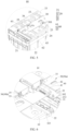
FIG. 1 is a plan view of a battery pack of the present disclosure; -
FIG. 2 is an enlarged view of part I inFIG. 1 of the present disclosure; -
FIG. 3 is an enlarged view of part II inFIG. 1 of the present disclosure; -
FIG. 4 is a structural view of a battery module of the present disclosure; -
FIG. 5 is an enlarged view of part III inFIG.4 of the present disclosure; -
FIG. 6 is an enlarged view of part IV inFIG.4 of the present disclosure; -
FIG. 7 is an enlarged view of part V inFIG.4 of the present disclosure; -
FIG. 8 is a structural view of an end plate of the present disclosure; -
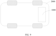
FIG. 9 is a structural view of an electricity-consumption device of the present disclosure. - Illustration of reference signs: 1000-battery pack, 10-battery management system, 20-battery module, 20a-first battery module, 20b-second battery module, 21-end plate, 211-first circuit board fixing seat, 212-second circuit board fixing seat, 22-battery cell, 23-connector, 24-binding tape, 25-positioning pin, 30-circuit board, 301-collection component, 302-reinforcement plate, 30a-first circuit board, 31-first rigid connecting portion, 311-adapter, 3111-second interface, 3112-second plug, 32-second rigid connecting portion, 33-flexible connecting portion, 30b-second circuit board, 35-flexible bending portion, 36- clearance hole, 40-connector assembly, 41-first interface, 42-first plug, 50- wire, 60-circuit board support, 61-support portion, 62-wing plate portion, 621-positioning strip, 63-positioning portion, 70-housing, 2000-electricity-consumption device.
- The following clearly and completely describes the technical solutions in the embodiments of the present disclosure with reference to the accompanying drawings in the embodiments of the present disclosure. Apparently, the described embodiments are some rather than all of the embodiments of the present disclosure. All other embodiments obtained by persons of ordinary skill in the art based on the embodiments of the present disclosure without creative efforts fall within the protection scope of the present disclosure.
- In the present disclosure, the terms such as "upper", "lower", "left", "right", "front", "rear", "top", "bottom", "inner", "outer", "vertical", "horizontal", "lateral", and "longitudinal" indicate orientation or position relationship based on the orientation or position relationship illustrated in the drawings. These terms are primarily intended to better describe the present disclosure and its embodiments and are not used to define the indicated device, element or component must have a particular orientation, or be constructed and operated in a particular orientation.
- Moreover, the above partial terms may be used to indicate other meanings in addition to the orientation or position relationship, for example, the term "upper" may also be used to indicate a certain dependency or connection relationship in some cases. To those of ordinary sill in the art, the specific meaning of the above terms in the present disclosure can be understood in the specific circumstances.
- In additional, the terms "installation", "set up", "dispose with", "connection", "connect to" should be understood in a broad sense. For example, they can be fixed connection, detachable connection, or integrated connection; they can be mechanical connection, or electrical connection; they can be directly connection, or they can be indirectly connection through an intermediate media, or they can be internal connection between two devices, two elements or two components. For those of ordinary skill in the art, the specific meaning of the above terms in the present disclosure can be understood according to the specific circumstances.
- In additional, the terms such as "the second", "the first" are primarily used to differentiate different devices, elements or components (specific types and constructions may be the same of different), and are not used to indicate or imply the relative importance and quantity of the indicated device, element or component. Unless otherwise stated, "plurality" means two or more.
- In the related art, voltage and temperature parameters of a battery pack are usually transmitted to the Battery Management System (BMS) through a wiring harness. However, a voltage and temperature collection terminal of a battery module is often positioned far away from the interface terminal of the BMS, which requires the wiring harness to have sufficient length, which leads to the wiring harness occupying too much internal space of the battery pack, resulting in a low utilization rate of the internal space of the battery space and a large number of wiring harness arrangements, complicated wiring harness and poor electrical safety. Therefore, the technical solution of the present disclosure is described below with reference to
Fig. 1 to Fig. 9 . - Referring to
Fig. 1 ,Fig. 4 andFig. 5 , the present disclosure discloses a battery pack, including abattery management system 10, a plurality ofbattery modules 20, a plurality ofcircuit boards 30 and a plurality ofconnector assemblies 40. The battery management system is also called the "brain" of a battery operating system, to send and receive information of the battery and each external port, and then to transmit the work command after in-depth analysis and processing of information. - As illustrated in
Fig. 4 andFig. 5 , thebattery module 20 is an energy storage component in the battery pack. Eachbattery module 20 includes a plurality ofbattery cells 22 sequentially arranged along a length direction of thebattery module 20.End plates 21 are respectively provided at two end portions of thebattery module 20 along a length direction of thebattery module 20. The plurality ofbattery cells 22 are located between the twoend plates 21. A plurality ofconnectors 23 are arranged at the top of thebattery module 20 and adjacent to thecircuit board 30. Eachconnector 23 is electrically connected to a positive terminal of one of adjacent twobattery cells 22 and a negative terminal of the other one of the adjacent twobattery cells 22, to connect the plurality ofbattery cells 22 in series, thereby meeting the operational requirements of thebattery module 20. The battery module20 also includes abinding tape 24. Thebinding tape 24 encircles the twoend plates 21 and the plurality ofbattery cells 22 to realize binding of the plurality ofbattery cells 22, so as to stabilize the structure of the formedbattery module 20. The battery pack can be provided with the plurality ofbattery modules 20, and thebattery modules 20 can be arranged in sequence to form a module string. The module string can extend along a length direction of the battery pack. - The
circuit boards 30 correspond one-to-one with thebattery modules 20. Onecircuit board 30 is arranged at the top of eachbattery module 20. Thecircuit board 30 is connected to eachbattery cell 22 in thebattery module 20 to collect operating data from eachbattery cell 22. Specifically, the plurality ofconnectors 23 as illustrated inFig. 5 are arranged on both sides of the top of thebattery module 20. Thecircuit board 30 is arranged at the middle of the top of thebattery module 20. Theconnectors 23 are arranged on both sides of thecircuit board 30 in the width direction of thecircuit board 30, and are arranged at intervals along the length direction of thecircuit board 30. Thecircuit board 30 is electrically connected to theconnectors 23 viacollection components 301, and thecollection components 301 are connected to theconnectors 23 in one-to-one correspondence. Thecircuit board 30 collects operating data from eachbattery cell 22 through thecollection component 301. The operation data is selected from the group consisting of voltage data, current data, and temperature data. - As illustrated in
Fig. 6 , theconnector assembly 40 includes afirst interface 41 and afirst plug 42. One of two adjacent circuit boards is connected to thefirst interface 41, and the other one is connected to thefirst plug 42. The twoadjacent circuit boards 30 are connected to each other through theconnector assembly 40 so that theplurality circuit boards 30 are connected in series to form a circuit board string. - The circuit board string is connected to the
battery management system 10 to transmit the operating data such as voltage data, current data and temperature data of eachbattery cell 22 in thebattery module 20 to thebattery management system 10. Compared with the collection method through the wiring harness, the collection method through thecircuit board 30 is more space-saving, cost-effective and more reliable connection. Occupying smaller space is conducive to improving the space utilization rate inside the battery. At the same time, compared with the complex wiring harness layout, it can improve the safety of the electricity. - Alternatively" as illustrated in
Fig. 4 andFig. 7 , thecircuit board 30 connected with thebattery management system 10 has a first rigid connectingportion 31 at one end of thecircuit board 30 facing thebattery management system 10. The first rigid connectingportion 31 includes anadaptor 311, which is connected to thebattery management system 10 via awire 50. The provision of the first rigid connectingportion 31 can strengthen the rigidity of the end position of thecircuit board 30, so that the end of thecircuit board 30 has better structural stability, thereby ensuring that the structure of thecircuit board 30 is resistant to deformation. - Alternatively, as illustrated in
Fig. 1 andFig. 3 , theadaptor 311 includes asecond interface 3111 and asecond plug 3112 connected with each other. Thesecond interface 3111 or thesecond plug 3112 is provided on thewire 50, so that the connection and detachment of thewire 50 and the first rigid connectingportion 31 are facilitated through the detachable design between thewire 50 and theadaptor 311. - Alternatively" as illustrated in
Fig. 4 andFig. 7 , theend plate 21 of thebattery module 20 adjacent to thebattery management system 10 corresponding to thecircuit board 30 provided with the first rigid connectingportion 31, is provided with a first circuitboard fixing seat 211 connected with the first rigid connectingportion 31. The first circuitboard fixing seat 211 can be connected to theend plate 21 through a pin or the like. The first rigid connectingportion 31 can be connected to the first circuitboard fixing seat 211 through a bolt or other fastening types, further ensuring the connection stability of thecircuit board 30. - Alternatively" as illustrated in
Fig. 4 ,Fig. 6 andFig. 7 , one end of onecircuit board 30 facing adjacent anothercircuit board 30 is provided with a second rigid connectingportion 32. The second rigid connectingportion 32 is connected to the anothercircuit board 30 through theconnector assembly 40. The arrangement of the second rigid connectingportion 32 can also strengthen the rigidity of the end position of thecircuit board 30, so that the end of thecircuit board 30 has better structural stability. - Alternatively" as illustrated in
Fig. 6 , one of theend plates 21 of the battery module (20) away from thebattery management system 10 corresponding to thecircuit board 30 provided with the second rigid connectingportion 32, a top of which is provided with a second circuitboard fixing seat 212 connected with the second rigid connectingportion 32. The structure of the second circuitboard fixing seat 212 can be the same as or different from the first circuit board fixing seat 211). The second circuitboard fixing seat 212 can also be connected to theend plate 21 by means such as a pin. The second rigid connectingportion 32 can be connected to the second circuitboard fixing seat 212 by means such as a bolt, further ensuring the connection stability of thecircuit board 30. - More specifically, the
battery module 20 adjacent to thebattery management system 10 is afirst battery module 20a. Thecircuit board 30 provided on thefirst battery module 20a is afirst circuit board 30a. The middle part of thefirst circuit board 30a is a flexible connectingportion 33. The two ends of thefirst circuit board 30a are respectively the first rigid connectingportion 31 and the second rigid connectingportion 32 connected to the flexible connectingportion 33. The flexible connectingportion 33 is connected to eachbattery cell 22 of thefirst battery module 20a, so that thefirst circuit board 30a can ensure flexibility while ensuring rigidity at both ends, thereby ensuring the connection stability with theadjacent circuit board 30 and thewire 50. - One of the
end plates 21 of thefirst battery module 20a is provided with a first circuitboard fixing seat 211 to connect to the first rigid connectingportion 31, and the other is provided with a second circuitboard fixing seat 212 to connect to the second rigid connectingportion 32, thereby ensuring connection stability. - Alternatively, one
circuit board 30 has aflexible bending portion 35 at one end of the onecircuit board 30 facing adjacent anothercircuit board 30. Theflexible bending portion 35 is suspended above installation reserved mounting gap between the twoadjacent battery modules 20, and theflexible bending portion 35 connects to the anothercircuit board 30 through theconnector assembly 40. Theflexible bending portion 35 makes thecircuit board 30 has a flexible deformation part. Aposition or shape of theflexible bending portion 35 can be adjusted to accommodate changes in position or distance between the twoadjacent battery modules 20, thus facilitating the connection of the twoadjacent battery modules 20. At the same time, thecircuit board 30 can reserve a redundant part through the flexible bending 35 to prevent the connection failure between the twointerconnected circuit boards 30 caused by mutual pulling due to abnormal shaking of the battery pack and other external factors. - Alternatively, as illustrated in
Fig. 4 andFig. 6 , one of theend plates 21 of thebattery module 20 corresponding to the onecircuit board 30 having theflexible bending portion 35, is spaced apart from theflexible bending portion 35 in the height direction of thebattery module 20. This can prevent theend plate 21 from squeezing and interfering with theflexible bending portion 35, and reserve enough space for theflexible bending portion 35 to fully deform to adapt to the changes in position or distance between theadjacent battery modules 20. - More specifically, the
battery module 20 includes afirst battery module 20a and asecond battery module 20b sequentially arranged along the length direction of the battery pack. Thecircuit board 30 includes thefirst circuit board 30a arranged at the top of thefirst battery module 20a and thesecond circuit board 30b arranged at the top of thesecond battery module 20b. Thesecond circuit board 30b includes a flexible connectingportion 33 and aflexible bending portion 35 connected to each other. Theflexible bending portion 33 of thesecond circuit board 30b is connected to eachbattery cell 22 of thesecond battery module 20b, and thesecond circuit board 30b is connected to thefirst circuit board 30a through theflexible bending portion 35 and theconnector assembly 40. - Furthermore, as mentioned above, the battery pack in this disclosure can be formed into a module string by only two
battery modules 20, that is, the aforementionedfirst battery module 20a and thesecond battery module 20b are sequentially arranged to form the module string. The battery pack can have a plurality of module strings arranged side by side to ensure the capacity of the battery pack. The top of thefirst battery module 20a is provided with thefirst circuit board 30a, and thefirst circuit board 30a is rigidly reinforced at both ends to ensure good connection stability with thefirst battery module 20a, thewire 50 and thesecond circuit board 30b. The top of thesecond battery module 20b is provided with thesecond circuit board 30b. Thesecond circuit board 30b is flexible and adjustable through theflexible bending portion 35 to ensure the connection effectiveness between thesecond circuit board 30b and thefirst circuit board 30a, and to prevent the connection failure between thesecond circuit board 30b and thefirst circuit board 30a by the redundant part reserved by theflexible bending portion 35. - Alternatively, the module string may also include three or
more battery modules 20, such as a plurality offirst battery modules 20a and onesecond battery module 20b, or onefirst battery module 20a and a plurality ofsecond battery modules 20b, etc., which are not described in detail here. - Alternatively, as illustrated in
Figs. 4 to 6 , the battery pack also includes a plurality of circuit board supports 60. One circuit board support 60 is arranged at the top of eachbattery module 20. The circuit board support 60 includes asupport portion 61 and awing portion 62 connected to each other. Thesupport portion 61 is arranged between thecircuit board 30 and thebattery module 20. Thewing portion 62 is staggered with thecircuit board 30. Thesupport portion 61 provides a structural support to thecircuit board 30 to maintain the structural stability and deformation resistance of thecircuit board 30. - Alternatively, as illustrated in
Figs 4 to 6 , thesupport portion 61 is arranged between the flexible connectingportion 33 ofcircuit board 30 and thebattery module 20. Thewing portion 62 has apositioning strip 621 at a side closer to theflexible bending portion 35 of thecircuit board 30. Thepositioning trip 621 extends towards thecircuit board 30 to position thecircuit board 30 along the width direction of the battery pack. More specifically, for thesecond circuit board 30b, thewing portion 62 can achieve prepositioning of theflexible bending portion 35 through thepositioning strip 621, facilitating its rapid connection to thefirst circuit board 30a. - Alternatively, the
wing portion 62 has apositioning portion 63 extending from the top of thebattery module 20 to the bottom of thebattery module 20 at an edge of thewing plate 62 away from thesupport portion 61. The positioningportion 63 is configured to position thebattery cells 22 in thebattery module 20 in the width direction of the battery pack. The positioningportion 63 can work with the bindingtape 24 to further fix the position of thebattery cells 22, preventing thebattery cells 22 from abnormal shaking and detaching from the original positions, thereby ensuring the overall structural stability of thebattery module 20. - Alternatively, as illustrated in the
Fig. 5 , a top of thebattery module 20, adjacent to thecircuit board 30, is provided with apositioning pin 25, thecircuit board 30 has a positioning hole. Thepositioning pin 25 are positioned through the positioning holes. In this way, the abnormal sliding of thecircuit board 30 can be prevented, especially to prevent thecircuit board 30 from creeping along the length direction of the battery pack. Furthermore, the positioning pins 25 can be set multiple along the length direction of the battery pack, and the positioning holes on thecircuit board 30 are set multiple, with multiple positioning holes corresponding to multiple positioning pins 25 one by one to improve the positioning effect. - Alternatively, as illustrated in
Fig. 5 , thecircuit board 30 has a plurality ofclearance holes 36, and the plurality ofclearance holes 36 correspond one- to- one with a plurality of explosion-proof valves arranged on the plurality ofbattery cells 22 in thebattery module 20, to reserve the pressure relief space required by the explosion-proof valve when thebattery cells 22 need to release pressure. - Alternatively, the
circuit boards 30 are flexible circuit boards, the overall material of which is soft and easy to layout, and the wire diameter of which is small to save layout space. - Alternatively, the plurality of
battery modules 20 are arranged in an array. The plurality ofcircuit boards 30 are arranged in an array. The plurality ofcircuit boards 30 in the same column connected in series to form a circuit board string. Circuit board strings are arranged in parallel at intervals along the width direction of battery pack. Thebattery management system 10 is connected in parallel with the plurality of circuit board strings, so that the battery pack has a larger storage capacity and can effectively collect working condition data such as voltage data, current data and temperature data. - Alternatively, the battery pack may further include a
housing 70. Thebattery management system 10, thebattery modules 20 and thecircuit boards 30 are all arranged in thehousing 70. Thehousing 70 provides mounting basis and masking protection for related components of the battery pack. - The disclosure also discloses an electricity-consumption device, which includes the
aforementioned battery pack 1000. The electricity-consumption device can be an electric vehicle, electric toy, electric tool, electric car, ship and spacecraft, mobile phone, portable device, personal digital assistant (PDA), laptop computer, etc. Taking avehicle 2000 shown inFig. 9 as an example, thebattery pack 1000 can be installed in the vehicle to power it, further details are not provided here. - It should be noted that the foregoing examples are provided solely for the purpose of illustrating the technical solutions of the present invention and are not intended as limitations. Although a detailed description of the present invention has been provided with reference to the aforementioned examples, those skilled in the art should understand that they may still modify the technical solutions disclosed in the aforementioned examples, or make equivalent substitutions for some or all of the technical features; and such modifications or substitutions do not cause the essence of the corresponding technical solutions to deviate from the scope of the technical solutions of the present invention as illustrated in the examples.
Claims (15)
- A battery pack, comprising:a battery management system (10) ;a plurality of battery modules (20), each battery module (20) comprising a plurality of battery cells (22) sequentially arranged along a length direction of the battery module (20);a plurality of circuit boards (30), one circuit board (30) being arranged at the top of each battery module (20), the circuit board (30) connecting each battery cell (22) in the battery module (20) to collect operating data from each battery cell (22);a plurality of connector assemblies (40), each connector assembly (40) comprising a first interface (41) and a first plug (42) connected to each other, one of two adjacent circuit boards (30) being connected to the first interface (41), and the other one being connected to the first plug (42); the two adjacent circuit boards (30) being connected to each other through the connector assembly (40) , so that the plurality of circuit boards (30) are connected in series to form a circuit board string; andthe circuit board string being connected to the battery management system (10) to transmit the operating data of each battery cell (22) in each battery module (20) to the battery management system (10).
- The battery pack of claim 1, wherein a plurality of connectors (23) are arranged at the top of the battery module (20) and adjacent to the circuit board, each connector (23) is electrically connected to a positive terminal of one of adjacent two battery cells (22) and a negative terminal of the other one of the adjacent two battery cells (22), to connect the plurality of battery cells (22) in series;the circuit board (30) is arranged at the middle of the top of the battery module (20), the connectors (23) are arranged on both sides of the circuit board (30) in a width direction and arranged at intervals along a length direction of the circuit board (30), the circuit board (30) is electrically connected to the connectors (23) via collection components, and the collection components (301) are connected to the connectors (23) in one-to-one correspondence; andthe circuit board (30) collects operating data from each battery cell (22) through the collection components (301).
- The battery pack of claim 1, wherein each battery module (20) comprises end plates (21) and a binding tape(24);
the end plates (21) are respectively provided at two end portions of the battery module (20) along the length direction of the battery module (20); the plurality of battery cells (22) are located between the two end plates (21), and the binding tape (24) encircles the two end plates (21) and the plurality of battery cells (22). - The battery pack of claim 4, wherein the circuit board (30) connected with the battery management system (10) has a first rigid connecting portion (31) at one end of the circuit board (30) facing the battery management system (10);the first rigid connecting portion (31) comprises an adapter (311), and the adapter (311) is connected to the battery management system (10) via a wire (50);the adapter (311) comprises a second interface (3111) and a second plug (3112) connected to each other; andthe second interface (3111) or the second plug (3112) is connected to the wire (50).
- The battery pack of claim 5, wherein the end plate (21) of the battery module (20) adjacent to the battery management system (10) corresponding to the circuit board (30) provided with the first rigid connecting portion (31), is provided with a first circuit board fixing seat (211) connected with the first rigid connecting portion (31).
- The battery pack of claim 5, wherein one end of one circuit board (30) facing adjacent another circuit board (30) is provided with a second rigid connecting portion (32), and the second rigid connecting portion (32) is connected to the another circuit board (30) through the connector assembly (40).
- The battery pack of claim 8, wherein one of the end plates (21) of the battery module (20) away from the battery management system (10) corresponding to the circuit board (30) provided with the second rigid connecting portion (32), a top of which is provided with a second circuit board fixing seat (211) connected with the second rigid connecting portion (32).
- The battery pack of claim 5, wherein one circuit board (30) has a flexible bending portion (35) at one end of the one circuit board (30) facing adjacent another circuit board (30);
the flexible bending portion (35) is suspended above a reserved mounting gap between the two adjacent battery modules (20), and the flexible bending portion (35) connects to the another circuit board (30) through the connector assembly(40). - The battery pack of claim 10, wherein one of the end plates (21) of the battery module (20) corresponding to the one circuit board (30) having the flexible bending portion (35), is spaced apart from the flexible bending portion (35) in the height direction of the battery module (20).
- The battery pack of claim 1, further comprising a plurality of circuit board supports (60), one circuit board support (60) is arranged at the top of each battery module (20);the circuit board support (60) comprising a support portion (61) and a wing portion (62) connected to each other;wherein the support portion (61) is arranged between the circuit board (30) and the battery module (20), and the wing portion (60) is staggered with the circuit board (30).
- The battery pack of claim 12, wherein the support portion (61) is arranged between the circuit board (30) and the battery module (20), and the wing plate portion (62) has a positioning strip (621) on a side closer to the circuit board (30), the positioning strip (621) extends towards the circuit board (30) to position the circuit board (30) along the width direction of the battery module (20).
- The battery pack of claim 13, wherein the wing portion (62) has a positioning portion (63) extending from the top of the battery module (20) to the bottom of the battery module (20) at an edge of the wing plate (62) away from the support portion (61), and the positioning portion (63) is configured to position the battery cells (22) in the battery module (20) in the width direction of the battery pack.
- The battery pack of claim 1, wherein a top of the battery module (20), adjacent to the circuit board (30), is provided with positioning pins (25);
the circuit board (30) has positioning holes, and the positioning pins (25) are positioned through the positioning holes. - The battery pack of claim 1, wherein the circuit board (30) has a plurality of clearance holes (36), and the plurality of clearance holes (36) correspond one-to-one with a plurality of explosion-proof valves arranged on the plurality of battery cells (22) in the battery module (20).
- An electricity-consumption device, comprising a battery pack as claimed in any one of claims 1 to 19.
Applications Claiming Priority (1)
| Application Number | Priority Date | Filing Date | Title |
|---|---|---|---|
| CN202311649170.8A CN117977123A (en) | 2023-12-01 | 2023-12-01 | Battery pack and electrical equipment |
Publications (1)
| Publication Number | Publication Date |
|---|---|
| EP4564518A1 true EP4564518A1 (en) | 2025-06-04 |
Family
ID=90854323
Family Applications (1)
| Application Number | Title | Priority Date | Filing Date |
|---|---|---|---|
| EP24216466.3A Pending EP4564518A1 (en) | 2023-12-01 | 2024-11-29 | Battery pack and electricity-consumption device |
Country Status (5)
| Country | Link |
|---|---|
| US (1) | US20250183495A1 (en) |
| EP (1) | EP4564518A1 (en) |
| CN (1) | CN117977123A (en) |
| AU (1) | AU2024388708A1 (en) |
| WO (1) | WO2025112673A1 (en) |
Families Citing this family (5)
| Publication number | Priority date | Publication date | Assignee | Title |
|---|---|---|---|---|
| CN117977123A (en) * | 2023-12-01 | 2024-05-03 | 厦门海辰储能科技股份有限公司 | Battery pack and electrical equipment |
| CN118693449B (en) * | 2024-08-16 | 2024-11-08 | 深圳海辰储能科技有限公司 | Energy storage device and electric equipment |
| CN118693476B (en) * | 2024-08-16 | 2024-12-13 | 深圳海辰储能科技有限公司 | Energy storage device and electric equipment |
| CN120165189B (en) * | 2025-05-16 | 2025-09-02 | 浙江晶科储能有限公司 | Battery connection system of energy storage battery, energy storage battery device and electrical equipment |
| CN120749303A (en) * | 2025-09-05 | 2025-10-03 | 浙江晶科储能有限公司 | Battery device, energy storage system and electric equipment |
Citations (3)
| Publication number | Priority date | Publication date | Assignee | Title |
|---|---|---|---|---|
| WO2023128461A1 (en) * | 2021-12-27 | 2023-07-06 | 주식회사 엘지에너지솔루션 | Battery pack and energy storage device comprising same |
| WO2023158186A1 (en) * | 2022-02-16 | 2023-08-24 | 주식회사 엘지에너지솔루션 | Battery module containing insulating oil, and battery pack comprising same |
| CN219779143U (en) * | 2023-06-27 | 2023-09-29 | 宁德时代新能源科技股份有限公司 | Battery modules, battery packs and electrical devices |
Family Cites Families (7)
| Publication number | Priority date | Publication date | Assignee | Title |
|---|---|---|---|---|
| CN109638209A (en) * | 2018-12-17 | 2019-04-16 | 安捷利电子科技(苏州)有限公司 | A kind of battery signal acquisition harness and its bending technique with bending structure |
| KR20220129391A (en) * | 2021-03-16 | 2022-09-23 | 삼성에스디아이 주식회사 | battery pack |
| CN214848917U (en) * | 2021-03-31 | 2021-11-23 | 力神动力电池系统有限公司 | Battery module |
| CN218472233U (en) * | 2022-09-28 | 2023-02-10 | 湖北亿纬动力有限公司 | A CCS component and battery pack |
| CN218782309U (en) * | 2022-10-25 | 2023-03-31 | 湖北亿纬动力有限公司 | Signal acquisition device and battery module |
| CN219267788U (en) * | 2023-03-24 | 2023-06-27 | 合肥国轩高科动力能源有限公司 | Single voltage and temperature acquisition device for switching between battery modules |
| CN117977123A (en) * | 2023-12-01 | 2024-05-03 | 厦门海辰储能科技股份有限公司 | Battery pack and electrical equipment |
-
2023
- 2023-12-01 CN CN202311649170.8A patent/CN117977123A/en active Pending
-
2024
- 2024-08-16 AU AU2024388708A patent/AU2024388708A1/en active Pending
- 2024-08-16 WO PCT/CN2024/112828 patent/WO2025112673A1/en active Pending
- 2024-11-29 EP EP24216466.3A patent/EP4564518A1/en active Pending
- 2024-11-29 US US18/963,806 patent/US20250183495A1/en active Pending
Patent Citations (3)
| Publication number | Priority date | Publication date | Assignee | Title |
|---|---|---|---|---|
| WO2023128461A1 (en) * | 2021-12-27 | 2023-07-06 | 주식회사 엘지에너지솔루션 | Battery pack and energy storage device comprising same |
| WO2023158186A1 (en) * | 2022-02-16 | 2023-08-24 | 주식회사 엘지에너지솔루션 | Battery module containing insulating oil, and battery pack comprising same |
| CN219779143U (en) * | 2023-06-27 | 2023-09-29 | 宁德时代新能源科技股份有限公司 | Battery modules, battery packs and electrical devices |
Also Published As
| Publication number | Publication date |
|---|---|
| AU2024388708A1 (en) | 2026-04-16 |
| CN117977123A (en) | 2024-05-03 |
| WO2025112673A1 (en) | 2025-06-05 |
| US20250183495A1 (en) | 2025-06-05 |
Similar Documents
| Publication | Publication Date | Title |
|---|---|---|
| EP4564518A1 (en) | Battery pack and electricity-consumption device | |
| KR20200144422A (en) | Battery module and battery pack including the same | |
| KR102595716B1 (en) | Compact power relay assembly with high reliability | |
| CN219067174U (en) | A battery pack and electric vehicle | |
| CN218887477U (en) | Signal acquisition assembly and battery module | |
| EP3930084B1 (en) | Connection assembly, battery module, battery pack, device, and manufacturing method | |
| CN118402118A (en) | Submerged cooling battery module, battery pack including same, and vehicle | |
| CN218827660U (en) | Box body assembly for energy storage device, energy storage device and energy storage device control system | |
| CN218101500U (en) | Battery module structure | |
| CN217848195U (en) | Battery pack and power device | |
| CN100477335C (en) | Battery and assembled rack battery system | |
| CN222581410U (en) | Battery pack and vehicle | |
| CN221150112U (en) | Sampling assembly and battery pack equipped therewith | |
| CN219960188U (en) | Control box and battery pack | |
| CN219457865U (en) | Battery modules and battery packs | |
| CN214280155U (en) | Data acquisition device and battery module | |
| CN218343271U (en) | Electrically integrated modules for battery packs, battery packs and power units | |
| CN117060016A (en) | Battery cell | |
| CN213565456U (en) | A BMS management system installation structure and battery pack | |
| CN116315395A (en) | battery pack | |
| CN115911720A (en) | Battery pack and vehicle | |
| CN223502044U (en) | End plates, batteries and electrical devices | |
| CN112582760A (en) | Data acquisition device and battery module | |
| CN223884552U (en) | A battery box assembly, a battery box assembly stacked structure, and a power battery system. | |
| EP4560787A1 (en) | Battery module and vehicle |
Legal Events
| Date | Code | Title | Description |
|---|---|---|---|
| PUAI | Public reference made under article 153(3) epc to a published international application that has entered the european phase |
Free format text: ORIGINAL CODE: 0009012 |
|
| STAA | Information on the status of an ep patent application or granted ep patent |
Free format text: STATUS: REQUEST FOR EXAMINATION WAS MADE |
|
| AK | Designated contracting states |
Kind code of ref document: A1 Designated state(s): AL AT BE BG CH CY CZ DE DK EE ES FI FR GB GR HR HU IE IS IT LI LT LU LV MC ME MK MT NL NO PL PT RO RS SE SI SK SM TR |
|
| 17P | Request for examination filed |
Effective date: 20250502 |
|
| RAP1 | Party data changed (applicant data changed or rights of an application transferred) |
Owner name: HITHIUM TECH HK LIMITED |
|
| STAA | Information on the status of an ep patent application or granted ep patent |
Free format text: STATUS: EXAMINATION IS IN PROGRESS |
|
| 17Q | First examination report despatched |
Effective date: 20251204 |