EP4564498A1 - Apparatus and method for removing residual electrolyte from a secondary battery - Google Patents
Apparatus and method for removing residual electrolyte from a secondary battery Download PDFInfo
- Publication number
- EP4564498A1 EP4564498A1 EP24192125.3A EP24192125A EP4564498A1 EP 4564498 A1 EP4564498 A1 EP 4564498A1 EP 24192125 A EP24192125 A EP 24192125A EP 4564498 A1 EP4564498 A1 EP 4564498A1
- Authority
- EP
- European Patent Office
- Prior art keywords
- case
- electrolyte
- absorption member
- moving
- electrolyte absorption
- Prior art date
- Legal status (The legal status is an assumption and is not a legal conclusion. Google has not performed a legal analysis and makes no representation as to the accuracy of the status listed.)
- Pending
Links
Images




Classifications
-
- H—ELECTRICITY
- H01—ELECTRIC ELEMENTS
- H01M—PROCESSES OR MEANS, e.g. BATTERIES, FOR THE DIRECT CONVERSION OF CHEMICAL ENERGY INTO ELECTRICAL ENERGY
- H01M10/00—Secondary cells; Manufacture thereof
- H01M10/04—Construction or manufacture in general
- H01M10/0404—Machines for assembling batteries
- H01M10/0409—Machines for assembling batteries for cells with wound electrodes
-
- H—ELECTRICITY
- H01—ELECTRIC ELEMENTS
- H01M—PROCESSES OR MEANS, e.g. BATTERIES, FOR THE DIRECT CONVERSION OF CHEMICAL ENERGY INTO ELECTRICAL ENERGY
- H01M50/00—Constructional details or processes of manufacture of the non-active parts of electrochemical cells other than fuel cells, e.g. hybrid cells
- H01M50/60—Arrangements or processes for filling or topping-up with liquids; Arrangements or processes for draining liquids from casings
- H01M50/691—Arrangements or processes for draining liquids from casings; Cleaning battery or cell casings
-
- B—PERFORMING OPERATIONS; TRANSPORTING
- B08—CLEANING
- B08B—CLEANING IN GENERAL; PREVENTION OF FOULING IN GENERAL
- B08B1/00—Cleaning by methods involving the use of tools
- B08B1/10—Cleaning by methods involving the use of tools characterised by the type of cleaning tool
- B08B1/14—Wipes; Absorbent members, e.g. swabs or sponges
-
- B—PERFORMING OPERATIONS; TRANSPORTING
- B08—CLEANING
- B08B—CLEANING IN GENERAL; PREVENTION OF FOULING IN GENERAL
- B08B1/00—Cleaning by methods involving the use of tools
- B08B1/30—Cleaning by methods involving the use of tools by movement of cleaning members over a surface
-
- B—PERFORMING OPERATIONS; TRANSPORTING
- B65—CONVEYING; PACKING; STORING; HANDLING THIN OR FILAMENTARY MATERIAL
- B65H—HANDLING THIN OR FILAMENTARY MATERIAL, e.g. SHEETS, WEBS, CABLES
- B65H5/00—Feeding articles separated from piles; Feeding articles to machines
- B65H5/06—Feeding articles separated from piles; Feeding articles to machines by rollers or balls, e.g. between rollers
- B65H5/062—Feeding articles separated from piles; Feeding articles to machines by rollers or balls, e.g. between rollers between rollers or balls
-
- H—ELECTRICITY
- H01—ELECTRIC ELEMENTS
- H01M—PROCESSES OR MEANS, e.g. BATTERIES, FOR THE DIRECT CONVERSION OF CHEMICAL ENERGY INTO ELECTRICAL ENERGY
- H01M10/00—Secondary cells; Manufacture thereof
- H01M10/04—Construction or manufacture in general
- H01M10/0404—Machines for assembling batteries
-
- H—ELECTRICITY
- H01—ELECTRIC ELEMENTS
- H01M—PROCESSES OR MEANS, e.g. BATTERIES, FOR THE DIRECT CONVERSION OF CHEMICAL ENERGY INTO ELECTRICAL ENERGY
- H01M10/00—Secondary cells; Manufacture thereof
- H01M10/04—Construction or manufacture in general
- H01M10/0422—Cells or battery with cylindrical casing
-
- H—ELECTRICITY
- H01—ELECTRIC ELEMENTS
- H01M—PROCESSES OR MEANS, e.g. BATTERIES, FOR THE DIRECT CONVERSION OF CHEMICAL ENERGY INTO ELECTRICAL ENERGY
- H01M10/00—Secondary cells; Manufacture thereof
- H01M10/05—Accumulators with non-aqueous electrolyte
- H01M10/052—Li-accumulators
-
- H—ELECTRICITY
- H01—ELECTRIC ELEMENTS
- H01M—PROCESSES OR MEANS, e.g. BATTERIES, FOR THE DIRECT CONVERSION OF CHEMICAL ENERGY INTO ELECTRICAL ENERGY
- H01M10/00—Secondary cells; Manufacture thereof
- H01M10/05—Accumulators with non-aqueous electrolyte
- H01M10/058—Construction or manufacture
-
- H—ELECTRICITY
- H01—ELECTRIC ELEMENTS
- H01M—PROCESSES OR MEANS, e.g. BATTERIES, FOR THE DIRECT CONVERSION OF CHEMICAL ENERGY INTO ELECTRICAL ENERGY
- H01M50/00—Constructional details or processes of manufacture of the non-active parts of electrochemical cells other than fuel cells, e.g. hybrid cells
- H01M50/10—Primary casings; Jackets or wrappings
- H01M50/102—Primary casings; Jackets or wrappings characterised by their shape or physical structure
- H01M50/107—Primary casings; Jackets or wrappings characterised by their shape or physical structure having curved cross-section, e.g. round or elliptic
-
- H—ELECTRICITY
- H01—ELECTRIC ELEMENTS
- H01M—PROCESSES OR MEANS, e.g. BATTERIES, FOR THE DIRECT CONVERSION OF CHEMICAL ENERGY INTO ELECTRICAL ENERGY
- H01M50/00—Constructional details or processes of manufacture of the non-active parts of electrochemical cells other than fuel cells, e.g. hybrid cells
- H01M50/10—Primary casings; Jackets or wrappings
- H01M50/147—Lids or covers
- H01M50/166—Lids or covers characterised by the methods of assembling casings with lids
- H01M50/167—Lids or covers characterised by the methods of assembling casings with lids by crimping
-
- Y—GENERAL TAGGING OF NEW TECHNOLOGICAL DEVELOPMENTS; GENERAL TAGGING OF CROSS-SECTIONAL TECHNOLOGIES SPANNING OVER SEVERAL SECTIONS OF THE IPC; TECHNICAL SUBJECTS COVERED BY FORMER USPC CROSS-REFERENCE ART COLLECTIONS [XRACs] AND DIGESTS
- Y02—TECHNOLOGIES OR APPLICATIONS FOR MITIGATION OR ADAPTATION AGAINST CLIMATE CHANGE
- Y02E—REDUCTION OF GREENHOUSE GAS [GHG] EMISSIONS, RELATED TO ENERGY GENERATION, TRANSMISSION OR DISTRIBUTION
- Y02E60/00—Enabling technologies; Technologies with a potential or indirect contribution to GHG emissions mitigation
- Y02E60/10—Energy storage using batteries
Definitions
- the disclosure relates to an apparatus for and method of removing an electrolyte from a case during a process of manufacturing a secondary battery.
- a cylindrical secondary battery includes a cylindrical electrode assembly, a cylindrical case (or can) accommodating the electrode assembly and an electrolyte, and a cap assembly coupled to an opening of one side of the can to seal the case and electrically connected to the electrode assembly to electrically connect an external component to the electrode assembly.
- the process of manufacturing the cylindrical secondary battery includes inserting a process of forming a beading part in a case to inject an electrolyte after inserting the electrode assembly into the cylindrical case.
- the electrolyte may remain in the beading part, and the residual electrolyte may cause damage to a current collector, a gasket, a cap plate, etc. that are coupled to the beading part depending on the electrolyte injection process.
- an amount of residual electrolyte accumulated in the beading part may increase to cause dimensional abnormalities after molding, contamination of an upper portion of the case, contaminations of molding equipment, etc., thereby causing difficulties for continuous production, etc.
- aspects of some embodiments of the present disclosure provide an apparatus and a method for effectively removing an electrolyte remaining in a beading part of a cylindrical secondary battery.
- an apparatus is configured to remove a residual electrolyte from a beading part of a case of a cylindrical secondary battery, the case may be configured to prevent separation of an electrode assembly.
- the apparatus may comprise an electrolyte absorption member providing part configured to provide an electrolyte absorption member to the case, a case moving part configured to move the case after the case has received an injection of an electrolyte, and an electrolyte absorption member moving part configured to move an area of the electrolyte absorption member onto the beading part of the case to absorb at least some of the residual electrolyte from the beading part.
- the electrolyte absorption member may include nonwoven fabric.
- the electrolyte absorption member providing part may be configured to move the electrolyte absorption member by unwinding the electrolyte absorption member from an unwinding roll so as to be wound around a winding roll.
- the electrolyte absorption member may include a flat plate sheet or uneven sheet into which the electrolyte is absorbed.
- the case moving part may include a case rotation part configured to rotate the case.
- the case moving part may be configured to move the case in a first direction
- the electrolyte absorption member moving part may include a jig configured to move the electrolyte absorption member in a second direction that is orthogonal to the first direction
- the jig may be configured to be rotatable (or to rotate).
- a bottom surface of the jig may be flat.
- a lower end of the jig may have a protruding blade (or may have protruding blade shape).
- a method for removing a residual electrolyte from a case including an electrolyte, an electrode assembly, and a beading part.
- the method comprises moving the case to contact an electrolyte absorption member, and moving an area of the electrolyte absorption member onto the beading part to absorb the residual electrolyte on the beading part.
- the electrolyte absorption member may include nonwoven fabric.
- the electrolyte absorption member may move in a roll-to-roll manner to provide the electrolyte absorption member.
- the electrolyte absorption member may include a flat plate sheet or uneven sheet for absorbing the electrolyte.
- Rotation of the case may be performed together with linear movement of the case.
- the case may move in a first direction
- the electrolyte absorption member may move in a second direction that is orthogonal to the first direction
- Moving an area of the electrolyte absorption member may include rotating a jig.
- a bottom surface of the jig may be flat.
- a lower end of the jig may have a protruding blade (or may have a protruding blade shape).
- Embodiments of the present disclosure may, however, be embodied in many different forms and should not be construed as being limited to the embodiments set forth herein; rather, these embodiments are provided so that those skilled in the art thoroughly understand the present disclosure. Rather, these embodiments are provided so that this disclosure will be thorough and complete, and will fully convey the scope of the present disclosure to those skilled in the art.
- first As used herein, terms such as “first,” “second,” etc. are used to describe various members, components, areas, layers, and/or portions. However, it is obvious that the members, components, areas, layers, and/or portions should not be defined by these terms. The terms do not mean a particular order, up and down, or superiority, and are used only for distinguishing one member, component, region, layer, or portion from another member, component, region, layer, or portion. Thus, a first member, component, region, layer, or portion which will be described may also refer to a second member, component, region, layer, or portion, without departing from the teaching of the present disclosure.
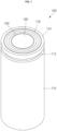
- FIG. 1 illustrates a perspective view of an example of a cylindrical secondary battery to which an apparatus and method for removing a residual electrolyte are applied according to some embodiments.
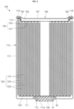
- FIG. 2 illustrates a cross-sectional view of the cylindrical secondary battery of FIG. 1 .
- a cylindrical secondary battery 100 may include a case 110, an electrode assembly 120 inside the case 110, a terminal 150 coupled to a terminal hole 111a defined in one end, e.g., a lower end, of the case 110, and a cap plate 160 that seals an opening defined in an opposite end, e.g., an upper end, of the case 110.
- the case 110 may include a circular bottom part 111 and a side part 112 extending a predetermined length upward from an edge of the bottom part 111.
- the bottom part 111 and the side part 112 of the case 110 may be integrated with each other.
- the circular bottom part 111 may have a flat circular plate shape and may be provided with a terminal hole 111a passing through a central portion of the circular bottom part 111.
- the terminal 150 may be inserted into and coupled to the terminal hole 111a of the bottom part 111.
- a first gasket 115 for sealing and electrical insulation may be further interposed between the terminal hole 111a and the terminal 150.
- the first gasket 115 may block contact between the terminal 150 and the case 110 to electrically separate the terminal 150 and the case 110 from each other.
- the terminal hole 111a of the bottom part 111 of the case 110 may be sealed by the first gasket 115.
- the first gasket 115 may be made of a resin material such as polyethylene (PE), polypropylene (PP), polyethylene terephthalate (PET), or the like.
- an upper portion of the case 110 may be opened during a manufacturing process.
- the electrode assembly 120 and an electrolyte may be inserted through an opened upper portion of the case 110.
- the cap plate 160 may be coupled to the opened upper portion to seal the inside of the case 110.
- the electrolyte may serve to facilitate movement of lithium ions between a positive electrode plate (e.g., a first electrode plate 121) and a negative electrode plate (e.g., a second electrode plate 122), which constitute the electrode assembly 120.
- the electrolyte may be a non-aqueous organic electrolyte such as a mixture of lithium salt and a high-purity organic solvent. Furthermore, the electrolyte may be a polymer using a polymer electrolyte or a solid electrolyte, and the type of the electrolyte is not limited.
- the case 110 may be made of steel, a steel alloy, aluminum, an aluminum alloy, or an equivalent thereof, but the material thereof is not limited thereto.
- a beading part 113 recessed inward may be defined in the case 110 at a lower portion of the case (or can) 110 with respect to the cap plate 160 to prevent the cap assembly from being separated to the outside.
- a inwardly bent crimping part 114 may be provided at an upper portion of the case (or can) 110. After the electrode assembly 120 is inserted through the opened lower end of the case 110, the beading part 113 may be provided to prevent the electrode assembly 120 from being separated from the case 110.
- the electrode assembly 120 may include a first electrode plate 121, a second electrode plate 122, and a separator 123.
- the first electrode plate 121 may be a positive electrode plate
- the second electrode plate 122 may be a negative electrode plate, or vice versa.
- the first electrode plate 121 will be referred to as the positive electrode plate
- the second electrode plate 122 will be referred to as the negative electrode plate.
- the first electrode plate 121 may be provided by applying a positive electrode active material made of transition metal oxide on at least one surface of plate-shaped metal foil made of aluminum (Al).
- the first electrode plate 121 may be provided with a positive electrode non-coating portion, which is not coated with the positive electrode active material, on a lower end thereof.
- the positive electrode non-coating portion may protrude downward from the electrode assembly 120.
- the positive electrode non-coating portion may further protrude downward than the second electrode plate 122 and the separator 123.
- the second electrode plate 122 may be coated with a negative electrode active material such as graphite or carbon on at least one surface of plate-shaped metal foil made of copper (Cu) or nickel (Ni).
- the second electrode plate 122 may be provided with a negative electrode non-coating portion, which is not coated with the negative electrode active material, on an upper end thereof.
- the negative electrode non-coating portion may protrude toward an upper side of the electrode assembly 120.
- the negative electrode non-coating portion of the second electrode plate 122 may further protrude upward than the first electrode plate 121 and the separator 123.
- the separator 123 may be made of a material such as polyethylene (PE) or polypropylene (PP), but the embodiments are not limited thereto.
- the separator 123 may be disposed between the first electrode plate 121 and the second electrode plate 122 to prevent a short circuit while allowing movement of lithium ions.
- the electrode assembly 120 may be wound from a winding front end in a substantially cylindrical shape after the first electrode plate 121, the second electrode plate 122, and the separator 123 are stacked.
- the positive electrode non-coating portion that is not coated with the positive electrode active material may protrude downward from the first electrode plate 121, and the negative electrode non-coating portion that is not coated with the negative electrode active material may protrude upward from the second electrode plate 122.
- a first current collector plate 130 may be a circular metal plate having a shape corresponding to a bottom surface of the electrode assembly 120.
- a planar size of the first current collector plate 130 may be equal to or less than a size of the bottom surface of the electrode assembly 120.
- the first current collector plate 130 may be made of aluminum (Al).
- the first current collector plate 130 may be fixed and electrically connected to the first electrode plate 121 exposed to the lower side of the electrode assembly 120, e.g., by welding the top surface of the first current collector plate 130 in contact with the bottom surface of the electrode assembly 120.
- the first current collector plate 130 may be fixed and electrically connected to the terminal 150 through welding in a state in which the bottom surface of the first current collector plate 130 is in contact with the top surface of the terminal 150.
- the first current collector plate 130 may serve as a path for a current flow between the first electrode plate 121 of the electrode assembly 120 and the terminal 150.
- the second current collector plate 140 may include a circular planar part 141 corresponding to the top surface of the electrode assembly 120 and an extension part 142 extending upward from an edge of the planar part 141.
- the planar part 141 may have a circular plate shape corresponding to the shape of the top surface of the electrode assembly 120, and a bottom surface of the planar part 141 may be in contact with the top surface of the electrode assembly 120.
- the bottom surface of the planar part 141 may be fixed and electrically connected to the second electrode plate 122 exposed to the upper side of the electrode assembly 120, e.g., by welding, so as to be in contact with the top surface of the electrode assembly 120.
- the extension part 142 may extend upward from an edge of the planar part 141.
- the extension part 142 may be in contact with and may be coupled to the beading part 113 of the case 110.
- the extension part 142 may be welded in contact with an inner surface of the beading part 113 of the case 110.
- the extension part 142 may be provided as a plurality of parts spaced apart from each other along the edge of the planar part 141.
- the second current collector plate 140 may serve as a path for current to flow between the second electrode plate 122 of the electrode assembly 120 and the case 110.
- the case 110 may be a negative electrode terminal.
- the terminal 150 may be inserted into a terminal hole 111a provided in the bottom part 111 of the case 110 and electrically connected to the first electrode collector plate 130.
- the terminal 150 may be a positive electrode terminal.
- the terminal 150 and the case 110 may have different polarities.
- the terminal 150 may be made of the same or similar material as each of the first current collector plate 130 and the first electrode plate 121.
- a diameter of a portion of the terminal 150 that is exposed to a lower side of the case 110, and/or a diameter disposed inside the case 110 may be greater than a diameter of the terminal 150 disposed in the terminal hole 111a.
- the terminal 150 may include a head 51, which is a portion exposed to the lower side of the case 110, and a coupling part 52, which is a portion disposed inside the case 110 to face the electrode assembly 120.
- the terminal 150 may be coupled to the terminal hole 111a of the case 110 inward from the outside.
- the head 51 may be disposed outside the case 110.
- the coupling part 52 may be compressed and deformed (e.g., compressed and molded) by riveting.
- the first gasket 115 may be pressed in an upper portion of the bottom part 111.
- the head 51 may be in contact with the lower portion of the bottom part 111 with the first gasket 115 therebetween.
- the first gasket 115 may be interposed between the terminal 150 and the terminal hole 111a to electrically insulate the terminal 150 and the case from each other and seal the terminal 150 and the case 110.
- the terminal 150 may be electrically connected to the first electrode plate 121 of the electrode assembly 120 through the first current collector plate 130.
- the first current collector plate 130 may serve as a path for current to flow between the first electrode plate 121 of the electrode assembly 120 and the terminal 150.
- the terminal 150 may be a positive electrode terminal.
- the cap plate 160 may be provided as a circular metal plate and may be coupled to an upper end of the case 110. A top surface of the cap plate 160 may be exposed to the outside. The cap plate 160 may be coupled to the upper end of the case 110 such that the second gasket 116 prevents electrical contact with the case 110. Because the cap plate 160 is not electrically connected to the positive electrode or the negative electrode of the electrode assembly 120, there may be no separate electrical polarity.
- the cap plate 160 may be made of aluminum, an aluminum alloy, or equivalent.
- the cap plate 160 may be provided as a metal plate and have a thickness of about 0.2 mm to about 1.5 mm.
- the cap plate 160 may include a center area 161 and an edge area 162, and the edge area 162 of the cap plate 160 may be disposed between the beading part 113 of the case 110 and the crimping part 114.
- the cap plate 160 may be seated on an upper portion such that the second gasket 116 is disposed on an upper portion of the beading part 113 of the case 110.
- the crimping part 114 of the case 110 may be bent to the inside of the cap plate 160 in a radial direction to press the second gasket 116, thereby fixing the cap plate 160 to the case 110.
- the second gasket 116 may be made of a resin material such as polyethylene (PE), polypropylene (PP), polyethylene terephthalate (PET), or the like.
- the second gasket 116 may press the case 110 and the cap plate 160 to seal a gap between the case 110 and the cap plate 160, thereby preventing the cap plate 160 from being separated from the case 110.
- the cap plate 160 may include a vent 163 defined in the central area 161 so as to be opened by a breaking pressure.
- the vent may be a notch defined from a top surface to a bottom surface of the cap plate 160.
- FIG. 3 illustrates a schematic view of the apparatus for removing the residual electrolyte according to embodiments
- FIG. 4 illustrates a schematic view of an electrolyte absorption member providing part of the apparatus for removing the residual electrolyte according to some embodiments.
- the electrolyte absorption member providing part 11 may provide an electrolyte absorption member 13 capable of absorbing the electrolyte remaining in the case 110, e.g., electrolyte remaining in the beading part 113 of the case 110.
- the electrolyte absorption member 13 may be a nonwoven fabric capable of absorbing the electrolyte, and the electrolyte absorption member providing part 11 may be configured to sequentially supply a non-woven fabric extending length-wise in a roll-to-roll manner.
- the electrolyte absorption member providing part 11 may include an unwinding roll 15 configured to unwind the electrolyte absorption member, i.e., the nonwoven fabric 13, and a winding roll 17 configured to wind the nonwoven fabric 13 from the unwinding roll 15.
- the nonwoven fabric 13 may be supplied while moving in a direction of the arrow depicted in FIG. 4 by rotation of the unwinding roll 15 and the winding roll 17.
- the electrolyte absorption member 13 may have a shape of a flat sheet or a shape of uneven sheet and electrolyte absorption member 13 may be capable of absorbing the electrolyte.
- the case moving part 21 may be configured to move the case 110 in a first direction D1.
- the case moving part 21 may be configured to sequentially move the case 110 to an area on which an electrolyte absorption process is performed.
- the case moving part 21 may be configured to move the case 110 in which the electrode assembly 120 is coupled, the beading part 113 is provided, and the electrolyte is injected.
- the case moving part 21 may be implemented using various driving devices capable of moving the case 110, such as a conveyor belt-based device or a robot device.
- the case moving part 21 may include a rotation part 23 configured to rotate the case 110 about a rotating axis X.
- the electrolyte absorption member moving part may be configured to move the nonwoven fabric 13 in a vertical direction D2 of the case 110.
- the electrolyte absorption member moving part may include a jig 31 configured to move in the vertical direction D2 of the case 110.
- the jig 31 may be configured to move in the vertical direction by an actuator and may be configured to be at least partially inserted into the case 110 while moving downward in FIG. 3 to press the nonwoven fabric 13. That is, as illustrated in FIG. 5 , the jig 31 may move in the downward direction D2 to press the nonwoven fabric 13, thereby causing deformation, that is, movement of the nonwoven fabric 13.
- the nonwoven fabric 13 may be folded to the beading part 113 within the case 110.
- the electrolyte remaining in the beading part 113 may be absorbed into the nonwoven fabric 13.
- a lower end of the jig 31 that is in contact with the nonwoven fabric 13 may be provided to be flat, thereby increasing in contact area with the nonwoven fabric 13, and as a result, absorption of the electrolyte may be promoted.
- the case 110 may rotate in the direction of the arrow to promote the absorption of the residual electrolyte.
- the jig 31 may move upward as indicated by an arrow as illustrated in FIG. 6 .
- the nonwoven fabric 13 may return to the position that the nonwoven fabric 13 was in before the pressing.
- the residual electrolyte in the case 110 may be removed, and the case moving part 21 may move under the jig 31 of the next case 110.
- the nonwoven fabric 13 may move by the operation of the unwinding roll 15 and the winding roll 15, thereby moving the portion of the nonwoven fabric 13 that absorbs the electrolyte. Then, the electrolyte may be absorbed again by moving the jig 31 downward.
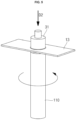
- FIG. 7 illustrates a view of a jig of an apparatus for removing a residual electrolyte according to other embodiments.
- a lower end of the jig 41 may include a protruding blade 43.
- the jig 41 may be configured to be movable in a vertical direction, similar to the embodiment described above.
- the protruding blade 43 may implement a structure that is capable of effectively pressing a nonwoven fabric 13.
- the jig 41 may be configured to rotate in a direction of an arrow around a vertical axis.
- the nonwoven fabric 13 may be effectively pressed through rotation of the jig 41 having the protruding blade 43, and thus, an electrolyte remaining in a beading part 113 may be effectively absorbed.
- the jig 41 may not rotate, but a case 110 accommodating an electrode assembly 120 may rotate instead of the jig 41.
- the electrolyte remaining in the beading part 113 may be effectively absorbed.
- the jig 41 may rotate in a first direction, and the case 110 may rotate in a second direction opposite to the first direction, and thus, the electrolyte remaining in the beading part 113 may be more effectively absorbed into a nonwoven fabric 13.
- the electrolyte remaining in the beading part of the cylindrical secondary battery may be removed through the residual electrode absorption device including the electrode absorption member providing part, the case moving part, and the electrolyte absorption member moving part.
Landscapes
- Chemical & Material Sciences (AREA)
- Chemical Kinetics & Catalysis (AREA)
- Electrochemistry (AREA)
- General Chemical & Material Sciences (AREA)
- Engineering & Computer Science (AREA)
- Manufacturing & Machinery (AREA)
- Mechanical Engineering (AREA)
- Cell Separators (AREA)
- Secondary Cells (AREA)
Abstract
An apparatus configured to remove a residual electrolyte from a beading part (113) of a case (110) of a cylindrical secondary battery (100), the case (110) being configured to prevent or reduce separation of an electrode assembly (120). The apparatus includes an electrolyte absorption member providing part (11) configured to provide an electrolyte absorption member (13) to the case (110), a case moving part (21) for coupling to the electrode assembly (120), wherein the case moving part (21) is configured to move the case (110) after the case (110) has received an injection of an electrolyte, and an electrolyte absorption member moving part (31) configured to move an area (161) of the electrolyte absorption member (13) onto the beading part (113) of the case (110) to absorb at least some of the residual electrolyte from the beading part (113).
Description
- The disclosure relates to an apparatus for and method of removing an electrolyte from a case during a process of manufacturing a secondary battery.
- A cylindrical secondary battery includes a cylindrical electrode assembly, a cylindrical case (or can) accommodating the electrode assembly and an electrolyte, and a cap assembly coupled to an opening of one side of the can to seal the case and electrically connected to the electrode assembly to electrically connect an external component to the electrode assembly.
- The process of manufacturing the cylindrical secondary battery includes inserting a process of forming a beading part in a case to inject an electrolyte after inserting the electrode assembly into the cylindrical case. The electrolyte may remain in the beading part, and the residual electrolyte may cause damage to a current collector, a gasket, a cap plate, etc. that are coupled to the beading part depending on the electrolyte injection process. In particular, if the beading part having a wide flat area is formed, an amount of residual electrolyte accumulated in the beading part may increase to cause dimensional abnormalities after molding, contamination of an upper portion of the case, contaminations of molding equipment, etc., thereby causing difficulties for continuous production, etc. Thus, it is desirable to remove the electrolyte remaining in the case, e.g., the beading part of the case, after the electrolyte injection.
- The above-described information disclosed in the technology that serves as the background of the present disclosure is only for improving understanding of the background of the present disclosure and thus may include information that does not constitute the related art.
- Aspects of some embodiments of the present disclosure provide an apparatus and a method for effectively removing an electrolyte remaining in a beading part of a cylindrical secondary battery.
- According to some embodiments, an apparatus is configured to remove a residual electrolyte from a beading part of a case of a cylindrical secondary battery, the case may be configured to prevent separation of an electrode assembly. The apparatus may comprise an electrolyte absorption member providing part configured to provide an electrolyte absorption member to the case, a case moving part configured to move the case after the case has received an injection of an electrolyte, and an electrolyte absorption member moving part configured to move an area of the electrolyte absorption member onto the beading part of the case to absorb at least some of the residual electrolyte from the beading part.
- The electrolyte absorption member may include nonwoven fabric.
- The electrolyte absorption member providing part may be configured to move the electrolyte absorption member by unwinding the electrolyte absorption member from an unwinding roll so as to be wound around a winding roll.
- The electrolyte absorption member may include a flat plate sheet or uneven sheet into which the electrolyte is absorbed.
- The case moving part may include a case rotation part configured to rotate the case.
- The case moving part may be configured to move the case in a first direction, and the electrolyte absorption member moving part may include a jig configured to move the electrolyte absorption member in a second direction that is orthogonal to the first direction.
- The jig may be configured to be rotatable (or to rotate).
- A bottom surface of the jig may be flat.
- A lower end of the jig may have a protruding blade (or may have protruding blade shape).
- According to some embodiments, a method is provided for removing a residual electrolyte from a case including an electrolyte, an electrode assembly, and a beading part. The method comprises moving the case to contact an electrolyte absorption member, and moving an area of the electrolyte absorption member onto the beading part to absorb the residual electrolyte on the beading part.
- The electrolyte absorption member may include nonwoven fabric.
- The electrolyte absorption member may move in a roll-to-roll manner to provide the electrolyte absorption member.
- The electrolyte absorption member may include a flat plate sheet or uneven sheet for absorbing the electrolyte.
- Rotation of the case may be performed together with linear movement of the case.
- The case may move in a first direction, and the electrolyte absorption member may move in a second direction that is orthogonal to the first direction.
- Moving an area of the electrolyte absorption member may include rotating a jig.
- A bottom surface of the jig may be flat.
- A lower end of the jig may have a protruding blade (or may have a protruding blade shape).
- All embodiments described in this specification may be advantageously combined with one another to the extent that their respective features are compatible. In particular, the expressions "according to an embodiment," "in an embodiment," "an embodiment of the invention provides" etc. mean that the respective features may or may not be part of specific embodiments of the present invention.
- The accompanying drawings are included to provide a further understanding of the present disclosure, and are incorporated in and constitute a part of this specification. The drawings illustrate exemplary embodiments of the present disclosure and, together with the description, serve to explain principles of the present disclosure.
-
FIG. 1 illustrates a perspective view illustrating an example of a cylindrical secondary battery to which an apparatus for and method of removing a residual electrolyte may be applied according to some embodiments. -
FIG. 2 illustrates a cross-sectional view of the cylindrical secondary battery ofFIG. 1 . -
FIG. 3 illustrates a schematic view of the apparatus for removing the residual electrolyte according to some embodiments. -
FIG. 4 illustrates a schematic view of an electrolyte absorption member providing part of the apparatus for removing the residual electrolyte according to some embodiments. -
FIG. 5 illustrates a view of a state in which a jig of the apparatus for removing the residual electrolyte presses nonwoven fabric according to some embodiments. -
FIG. 6 illustrates a view of a state in which a jig of the apparatus for removing the residual electrolyte moves vertically so that the nonwoven fabric returns to its original position according to some embodiments. -
FIG. 7 illustrates a view of a jig of an apparatus for removing a residual electrolyte according to some embodiments. - Hereinafter, embodiments will be described in detail with reference to the accompanying drawings.
- Embodiments of the present disclosure may, however, be embodied in many different forms and should not be construed as being limited to the embodiments set forth herein; rather, these embodiments are provided so that those skilled in the art thoroughly understand the present disclosure. Rather, these embodiments are provided so that this disclosure will be thorough and complete, and will fully convey the scope of the present disclosure to those skilled in the art.
- In addition, in the following drawings, the thickness or size of each layer is exaggerated for convenience and clarity of description, and the same reference numerals in the drawings refer to the same elements. As used herein, the term "and/or" includes any and all combinations of one or more of the associated listed items. In this specification, it will also be understood that if a member A is referred to as being connected to a member B, the member A can be directly connected to the member B or indirectly connected to the member B with a member B therebetween.
- The terms used in this specification are for illustrative purposes of the present disclosure only and should not be construed to limit the meaning or the scope of the present disclosure. As used in this specification, a singular form may, unless definitely indicating a particular case in terms of the context, include a plural form. Also, the expressions "comprise" and/or "comprising" used in this specification neither define the mentioned shapes, numbers, processes, operations, members, elements, and/or groups of these, nor exclude the presence or addition of one or more other different shapes, numbers, processes, operations, members, elements, and/or groups of these, or addition of these. The term "and/or" used herein includes any and all combinations of one or more of the associated listed items.
- As used herein, terms such as "first," "second," etc. are used to describe various members, components, areas, layers, and/or portions. However, it is obvious that the members, components, areas, layers, and/or portions should not be defined by these terms. The terms do not mean a particular order, up and down, or superiority, and are used only for distinguishing one member, component, region, layer, or portion from another member, component, region, layer, or portion. Thus, a first member, component, region, layer, or portion which will be described may also refer to a second member, component, region, layer, or portion, without departing from the teaching of the present disclosure.
- Spatially relative terms, such as "below", "beneath", "lower", "above", "upper" and the like, used herein for ease of description to describe one element or feature's relationship to another element(s) or feature(s) as illustrated in the figures. These spatially relative terms are intended for easy comprehension of the prevent invention according to various process states or usage states of the prevent invention, and thus, the present disclosure is not limited thereto. For example, an element or feature shown in the drawings is turned inside out, the element or feature described as "beneath" or "below" may change into "above" or "upper". Thus, the term "below" may encompass the term "above" or "below".
-
FIG. 1 illustrates a perspective view of an example of a cylindrical secondary battery to which an apparatus and method for removing a residual electrolyte are applied according to some embodiments.FIG. 2 illustrates a cross-sectional view of the cylindrical secondary battery ofFIG. 1 . - Referring to
FIGS. 1 and2 , a cylindricalsecondary battery 100 may include acase 110, anelectrode assembly 120 inside thecase 110, a terminal 150 coupled to aterminal hole 111a defined in one end, e.g., a lower end, of thecase 110, and acap plate 160 that seals an opening defined in an opposite end, e.g., an upper end, of thecase 110. - The
case 110 may include a circularbottom part 111 and aside part 112 extending a predetermined length upward from an edge of thebottom part 111. Thebottom part 111 and theside part 112 of thecase 110 may be integrated with each other. - The circular
bottom part 111 may have a flat circular plate shape and may be provided with aterminal hole 111a passing through a central portion of the circularbottom part 111. The terminal 150 may be inserted into and coupled to theterminal hole 111a of thebottom part 111. Afirst gasket 115 for sealing and electrical insulation may be further interposed between theterminal hole 111a and the terminal 150. Thefirst gasket 115 may block contact between the terminal 150 and thecase 110 to electrically separate the terminal 150 and thecase 110 from each other. Theterminal hole 111a of thebottom part 111 of thecase 110 may be sealed by thefirst gasket 115. Thefirst gasket 115 may be made of a resin material such as polyethylene (PE), polypropylene (PP), polyethylene terephthalate (PET), or the like. - In the cylindrical
secondary battery 100, an upper portion of thecase 110 may be opened during a manufacturing process. In some embodiments, during a process of manufacturing the cylindricalsecondary battery 100, theelectrode assembly 120 and an electrolyte may be inserted through an opened upper portion of thecase 110. As described above, after the electrolyte and theelectrode assembly 120 are inserted into thecase 110, thecap plate 160 may be coupled to the opened upper portion to seal the inside of thecase 110. Here, the electrolyte may serve to facilitate movement of lithium ions between a positive electrode plate (e.g., a first electrode plate 121) and a negative electrode plate (e.g., a second electrode plate 122), which constitute theelectrode assembly 120. The electrolyte may be a non-aqueous organic electrolyte such as a mixture of lithium salt and a high-purity organic solvent. Furthermore, the electrolyte may be a polymer using a polymer electrolyte or a solid electrolyte, and the type of the electrolyte is not limited. - The
case 110 may be made of steel, a steel alloy, aluminum, an aluminum alloy, or an equivalent thereof, but the material thereof is not limited thereto. In some embodiments, abeading part 113 recessed inward may be defined in thecase 110 at a lower portion of the case (or can) 110 with respect to thecap plate 160 to prevent the cap assembly from being separated to the outside. In some embodiments, a inwardly bent crimpingpart 114 may be provided at an upper portion of the case (or can) 110. After theelectrode assembly 120 is inserted through the opened lower end of thecase 110, thebeading part 113 may be provided to prevent theelectrode assembly 120 from being separated from thecase 110. - The
electrode assembly 120 may include afirst electrode plate 121, asecond electrode plate 122, and aseparator 123. Thefirst electrode plate 121 may be a positive electrode plate, and thesecond electrode plate 122 may be a negative electrode plate, or vice versa. Hereinafter, for convenience of description, thefirst electrode plate 121 will be referred to as the positive electrode plate, and thesecond electrode plate 122 will be referred to as the negative electrode plate. - The
first electrode plate 121 may be provided by applying a positive electrode active material made of transition metal oxide on at least one surface of plate-shaped metal foil made of aluminum (Al). In some embodiments, thefirst electrode plate 121 may be provided with a positive electrode non-coating portion, which is not coated with the positive electrode active material, on a lower end thereof. The positive electrode non-coating portion may protrude downward from theelectrode assembly 120. In some embodiments, the positive electrode non-coating portion may further protrude downward than thesecond electrode plate 122 and theseparator 123. - The
second electrode plate 122 may be coated with a negative electrode active material such as graphite or carbon on at least one surface of plate-shaped metal foil made of copper (Cu) or nickel (Ni). In some embodiments, thesecond electrode plate 122 may be provided with a negative electrode non-coating portion, which is not coated with the negative electrode active material, on an upper end thereof. The negative electrode non-coating portion may protrude toward an upper side of theelectrode assembly 120. In some embodiments, the negative electrode non-coating portion of thesecond electrode plate 122 may further protrude upward than thefirst electrode plate 121 and theseparator 123. - The
separator 123 may be made of a material such as polyethylene (PE) or polypropylene (PP), but the embodiments are not limited thereto. Theseparator 123 may be disposed between thefirst electrode plate 121 and thesecond electrode plate 122 to prevent a short circuit while allowing movement of lithium ions. - The
electrode assembly 120 may be wound from a winding front end in a substantially cylindrical shape after thefirst electrode plate 121, thesecond electrode plate 122, and theseparator 123 are stacked. In some embodiments, in theelectrode assembly 120, the positive electrode non-coating portion that is not coated with the positive electrode active material may protrude downward from thefirst electrode plate 121, and the negative electrode non-coating portion that is not coated with the negative electrode active material may protrude upward from thesecond electrode plate 122. - A first
current collector plate 130 may be a circular metal plate having a shape corresponding to a bottom surface of theelectrode assembly 120. A planar size of the firstcurrent collector plate 130 may be equal to or less than a size of the bottom surface of theelectrode assembly 120. The firstcurrent collector plate 130 may be made of aluminum (Al). The firstcurrent collector plate 130 may be fixed and electrically connected to thefirst electrode plate 121 exposed to the lower side of theelectrode assembly 120, e.g., by welding the top surface of the firstcurrent collector plate 130 in contact with the bottom surface of theelectrode assembly 120. The firstcurrent collector plate 130 may be fixed and electrically connected to the terminal 150 through welding in a state in which the bottom surface of the firstcurrent collector plate 130 is in contact with the top surface of the terminal 150. The firstcurrent collector plate 130 may serve as a path for a current flow between thefirst electrode plate 121 of theelectrode assembly 120 and the terminal 150. - The second
current collector plate 140 may include a circular planar part 141 corresponding to the top surface of theelectrode assembly 120 and anextension part 142 extending upward from an edge of the planar part 141. - The planar part 141 may have a circular plate shape corresponding to the shape of the top surface of the
electrode assembly 120, and a bottom surface of the planar part 141 may be in contact with the top surface of theelectrode assembly 120. The bottom surface of the planar part 141 may be fixed and electrically connected to thesecond electrode plate 122 exposed to the upper side of theelectrode assembly 120, e.g., by welding, so as to be in contact with the top surface of theelectrode assembly 120. - The
extension part 142 may extend upward from an edge of the planar part 141. Theextension part 142 may be in contact with and may be coupled to thebeading part 113 of thecase 110. In some embodiments, theextension part 142 may be welded in contact with an inner surface of thebeading part 113 of thecase 110. In some embodiments, theextension part 142 may be provided as a plurality of parts spaced apart from each other along the edge of the planar part 141. The secondcurrent collector plate 140 may serve as a path for current to flow between thesecond electrode plate 122 of theelectrode assembly 120 and thecase 110. In some embodiments, thecase 110 may be a negative electrode terminal. - The terminal 150 may be inserted into a
terminal hole 111a provided in thebottom part 111 of thecase 110 and electrically connected to the firstelectrode collector plate 130. In some embodiments, the terminal 150 may be a positive electrode terminal. The terminal 150 and thecase 110 may have different polarities. The terminal 150 may be made of the same or similar material as each of the firstcurrent collector plate 130 and thefirst electrode plate 121. In the terminal 150, a diameter of a portion of the terminal 150 that is exposed to a lower side of thecase 110, and/or a diameter disposed inside thecase 110, may be greater than a diameter of the terminal 150 disposed in theterminal hole 111a. - The terminal 150 may include a
head 51, which is a portion exposed to the lower side of thecase 110, and acoupling part 52, which is a portion disposed inside thecase 110 to face theelectrode assembly 120. The terminal 150 may be coupled to theterminal hole 111a of thecase 110 inward from the outside. In some embodiments, thehead 51 may be disposed outside thecase 110. In some embodiments, thecoupling part 52 may be compressed and deformed (e.g., compressed and molded) by riveting. Thus, thefirst gasket 115 may be pressed in an upper portion of thebottom part 111. In some embodiments, thehead 51 may be in contact with the lower portion of thebottom part 111 with thefirst gasket 115 therebetween. In some embodiments, thefirst gasket 115 may be interposed between the terminal 150 and theterminal hole 111a to electrically insulate the terminal 150 and the case from each other and seal the terminal 150 and thecase 110. The terminal 150 may be electrically connected to thefirst electrode plate 121 of theelectrode assembly 120 through the firstcurrent collector plate 130. - With the above-described structure, the first
current collector plate 130 may serve as a path for current to flow between thefirst electrode plate 121 of theelectrode assembly 120 and the terminal 150. In some embodiments, the terminal 150 may be a positive electrode terminal. - The
cap plate 160 may be provided as a circular metal plate and may be coupled to an upper end of thecase 110. A top surface of thecap plate 160 may be exposed to the outside. Thecap plate 160 may be coupled to the upper end of thecase 110 such that thesecond gasket 116 prevents electrical contact with thecase 110. Because thecap plate 160 is not electrically connected to the positive electrode or the negative electrode of theelectrode assembly 120, there may be no separate electrical polarity. Thecap plate 160 may be made of aluminum, an aluminum alloy, or equivalent. Thecap plate 160 may be provided as a metal plate and have a thickness of about 0.2 mm to about 1.5 mm. - The
cap plate 160 may include acenter area 161 and anedge area 162, and theedge area 162 of thecap plate 160 may be disposed between thebeading part 113 of thecase 110 and the crimpingpart 114. In some embodiments, thecap plate 160 may be seated on an upper portion such that thesecond gasket 116 is disposed on an upper portion of thebeading part 113 of thecase 110. Thereafter, the crimpingpart 114 of thecase 110 may be bent to the inside of thecap plate 160 in a radial direction to press thesecond gasket 116, thereby fixing thecap plate 160 to thecase 110. Thesecond gasket 116 may be made of a resin material such as polyethylene (PE), polypropylene (PP), polyethylene terephthalate (PET), or the like. Thesecond gasket 116 may press thecase 110 and thecap plate 160 to seal a gap between thecase 110 and thecap plate 160, thereby preventing thecap plate 160 from being separated from thecase 110. - The
cap plate 160 may include avent 163 defined in thecentral area 161 so as to be opened by a breaking pressure. The vent may be a notch defined from a top surface to a bottom surface of thecap plate 160. -
FIG. 3 illustrates a schematic view of the apparatus for removing the residual electrolyte according to embodiments, andFIG. 4 illustrates a schematic view of an electrolyte absorption member providing part of the apparatus for removing the residual electrolyte according to some embodiments. - Referring to
FIG. 4 , the electrolyte absorptionmember providing part 11 may provide anelectrolyte absorption member 13 capable of absorbing the electrolyte remaining in thecase 110, e.g., electrolyte remaining in thebeading part 113 of thecase 110. Theelectrolyte absorption member 13 may be a nonwoven fabric capable of absorbing the electrolyte, and the electrolyte absorptionmember providing part 11 may be configured to sequentially supply a non-woven fabric extending length-wise in a roll-to-roll manner. In some embodiments, as illustrated inFIG. 4 , the electrolyte absorptionmember providing part 11 may include an unwindingroll 15 configured to unwind the electrolyte absorption member, i.e., thenonwoven fabric 13, and a windingroll 17 configured to wind thenonwoven fabric 13 from the unwindingroll 15. Thenonwoven fabric 13 may be supplied while moving in a direction of the arrow depicted inFIG. 4 by rotation of the unwindingroll 15 and the windingroll 17. - The
electrolyte absorption member 13 may have a shape of a flat sheet or a shape of uneven sheet andelectrolyte absorption member 13 may be capable of absorbing the electrolyte. - The
case moving part 21 may be configured to move thecase 110 in a first direction D1. For example, as schematically illustrated inFIG. 3 , thecase moving part 21 may be configured to sequentially move thecase 110 to an area on which an electrolyte absorption process is performed. For example, thecase moving part 21 may be configured to move thecase 110 in which theelectrode assembly 120 is coupled, thebeading part 113 is provided, and the electrolyte is injected. Thecase moving part 21 may be implemented using various driving devices capable of moving thecase 110, such as a conveyor belt-based device or a robot device. In some embodiments, thecase moving part 21 may include arotation part 23 configured to rotate thecase 110 about a rotating axis X. - The electrolyte absorption member moving part may be configured to move the
nonwoven fabric 13 in a vertical direction D2 of thecase 110. The electrolyte absorption member moving part may include ajig 31 configured to move in the vertical direction D2 of thecase 110. Thejig 31 may be configured to move in the vertical direction by an actuator and may be configured to be at least partially inserted into thecase 110 while moving downward inFIG. 3 to press thenonwoven fabric 13. That is, as illustrated inFIG. 5 , thejig 31 may move in the downward direction D2 to press thenonwoven fabric 13, thereby causing deformation, that is, movement of thenonwoven fabric 13. Thus, thenonwoven fabric 13 may be folded to thebeading part 113 within thecase 110. As a result, the electrolyte remaining in thebeading part 113 may be absorbed into thenonwoven fabric 13. In some embodiments, a lower end of thejig 31 that is in contact with thenonwoven fabric 13 may be provided to be flat, thereby increasing in contact area with thenonwoven fabric 13, and as a result, absorption of the electrolyte may be promoted. In some embodiments, thecase 110 may rotate in the direction of the arrow to promote the absorption of the residual electrolyte. - After the absorption of the residual electrolyte is achieved, the
jig 31 may move upward as indicated by an arrow as illustrated inFIG. 6 . Thus, thenonwoven fabric 13 may return to the position that thenonwoven fabric 13 was in before the pressing. In some embodiments, the residual electrolyte in thecase 110 may be removed, and thecase moving part 21 may move under thejig 31 of thenext case 110. In some embodiments, thenonwoven fabric 13 may move by the operation of the unwindingroll 15 and the windingroll 15, thereby moving the portion of thenonwoven fabric 13 that absorbs the electrolyte. Then, the electrolyte may be absorbed again by moving thejig 31 downward. -
FIG. 7 illustrates a view of a jig of an apparatus for removing a residual electrolyte according to other embodiments. As illustrated inFIG. 7 , a lower end of thejig 41 may include a protrudingblade 43. Thejig 41 may be configured to be movable in a vertical direction, similar to the embodiment described above. The protrudingblade 43 may implement a structure that is capable of effectively pressing anonwoven fabric 13. In some embodiments, thejig 41 may be configured to rotate in a direction of an arrow around a vertical axis. Thenonwoven fabric 13 may be effectively pressed through rotation of thejig 41 having the protrudingblade 43, and thus, an electrolyte remaining in abeading part 113 may be effectively absorbed. Thejig 41 may not rotate, but acase 110 accommodating anelectrode assembly 120 may rotate instead of thejig 41. In some embodiments, as thecase 110 rotates, the electrolyte remaining in thebeading part 113 may be effectively absorbed. In some examples, thejig 41 may rotate in a first direction, and thecase 110 may rotate in a second direction opposite to the first direction, and thus, the electrolyte remaining in thebeading part 113 may be more effectively absorbed into anonwoven fabric 13. - According to the embodiments of the present disclosure, the electrolyte remaining in the beading part of the cylindrical secondary battery may be removed through the residual electrode absorption device including the electrode absorption member providing part, the case moving part, and the electrolyte absorption member moving part.
- The above-mentioned embodiment is merely an embodiment of the cylindrical secondary battery, and thus, the present disclosure is not limited to the foregoing embodiment, and also it will be understood by those of ordinary skill in the art that various changes in form and details may be made therein without departing from the scope of the present disclosure as defined by the appended claims and equivalents thereto.
Claims (15)
- An apparatus configured to remove a residual electrolyte from a beading part (113) of a case (110) of a cylindrical secondary battery (100), wherein the case (110) is configured to prevent separation of an electrode assembly (120), the apparatus comprising:an electrolyte absorption member providing part (11) configured to provide an electrolyte absorption member (13) to the case (110);a case moving part (21) configured to move the case (110) after the case (110) has received an injection of an electrolyte; andan electrolyte absorption member moving part configured to move an area (161) of the electrolyte absorption member (13) onto the beading part (113) of the case (110) to absorb at least some of the residual electrolyte from the beading part (113).
- The apparatus as claimed in claim 1, wherein the electrolyte absorption member (13) comprises a nonwoven fabric.
- The apparatus as claimed in claim 1 or 2, further comprising an unwinding roll (15) and a winding roll (17), wherein the electrolyte absorption member providing part (11) is configured to unwind the electrolyte absorption member (13) from the unwinding roll (15) and wind the electrolyte absorption member (13) around the winding roll (17).
- The apparatus as claimed in any one of the preceding claims, wherein the electrolyte absorption member (13) comprises a flat plate sheet or uneven sheet for absorbing the electrolyte.
- The apparatus as claimed in any one of the preceding claims, wherein the case moving part (21) comprises a case rotation part (23) configured to rotate the case (110).
- The apparatus as claimed in any one of the preceding claims, wherein the case moving part (21) is configured to move case (110) in a first direction (D1), and
the electrolyte absorption member moving part comprises a jig (31, 41) configured to move the electrolyte absorption member (13) in a second direction (D2) that is orthogonal to the first direction (D1). - The apparatus as claimed in claim 6, wherein the jig (31, 41) is configured to be rotatable.
- The apparatus as claimed in claim 6 or 7, wherein a bottom surface of the jig (31) is flat or wherein a lower end of the jig (41) has a protruding blade (43).
- A method of removing a residual electrolyte from a case (110) including an electrolyte, an electrode assembly (120), and a beading part (113), the method comprising:moving the case (110) to contact an electrolyte absorption member (13); andmoving an area (161) of the electrolyte absorption member (13) onto the beading part (113) to absorb the residual electrolyte on the beading part (113).
- The method as claimed in claim 9, wherein the electrolyte absorption member (13) comprises nonwoven fabric, and/or a flat plate sheet or uneven sheet for absorbing the electrolyte.
- The method as claimed in claim 9 or 10, wherein the electrolyte absorption member (13) moves in a roll-to-roll (15) manner.
- The method as claimed in any one of claims 9 to 11, wherein moving the case (110) comprises rotation of the case (110) and linear movement of the case (110).
- The method as claimed in any one of claims 9 to 12, wherein moving the case (110) comprises moving the case (110) in a first direction (D1), and
moving the area (161) of the electrolyte absorption member (13) comprises moving the area (161) of the electrolyte absorption member (13) a second direction (D2) that is orthogonal to the first direction (D1). - The method as claimed in claim 13, wherein moving the area (161) of the electrolyte absorption member (13) comprises rotating a jig (31, 41).
- The method as claimed in claim 14, wherein a bottom surface of the jig (31) is flat or wherein a lower end of the jig (41) has a protruding blade (43).
Applications Claiming Priority (1)
| Application Number | Priority Date | Filing Date | Title |
|---|---|---|---|
| KR1020230172071A KR20250083656A (en) | 2023-12-01 | 2023-12-01 | Apparatus and method for removing remaining electrolyte for secondary battery |
Publications (1)
| Publication Number | Publication Date |
|---|---|
| EP4564498A1 true EP4564498A1 (en) | 2025-06-04 |
Family
ID=92171907
Family Applications (1)
| Application Number | Title | Priority Date | Filing Date |
|---|---|---|---|
| EP24192125.3A Pending EP4564498A1 (en) | 2023-12-01 | 2024-07-31 | Apparatus and method for removing residual electrolyte from a secondary battery |
Country Status (4)
| Country | Link |
|---|---|
| US (1) | US20250183503A1 (en) |
| EP (1) | EP4564498A1 (en) |
| KR (1) | KR20250083656A (en) |
| CN (1) | CN120089916A (en) |
Citations (2)
| Publication number | Priority date | Publication date | Assignee | Title |
|---|---|---|---|---|
| JP2001110452A (en) * | 1999-10-07 | 2001-04-20 | Sony Corp | Manufacturing method of non-aqueous electrolyte battery |
| JP2020187937A (en) * | 2019-05-15 | 2020-11-19 | 株式会社豊田自動織機 | Method of manufacturing power storage module |
Family Cites Families (3)
| Publication number | Priority date | Publication date | Assignee | Title |
|---|---|---|---|---|
| JPH07263028A (en) * | 1994-03-25 | 1995-10-13 | Fuji Photo Film Co Ltd | Nonaqueous secondary battery |
| EP4112812A4 (en) * | 2020-02-26 | 2024-04-10 | ENTEK Asia Inc | Nonwoven fabric for lead acid storage batteries, said nonwoven fabric using glass fibers and thermally fusible binder fibers |
| KR20230067335A (en) * | 2021-11-09 | 2023-05-16 | 에스케이온 주식회사 | Manufacturing method for battery cell stack |
-
2023
- 2023-12-01 KR KR1020230172071A patent/KR20250083656A/en active Pending
-
2024
- 2024-05-23 US US18/673,281 patent/US20250183503A1/en active Pending
- 2024-07-31 EP EP24192125.3A patent/EP4564498A1/en active Pending
- 2024-08-02 CN CN202411055897.8A patent/CN120089916A/en active Pending
Patent Citations (2)
| Publication number | Priority date | Publication date | Assignee | Title |
|---|---|---|---|---|
| JP2001110452A (en) * | 1999-10-07 | 2001-04-20 | Sony Corp | Manufacturing method of non-aqueous electrolyte battery |
| JP2020187937A (en) * | 2019-05-15 | 2020-11-19 | 株式会社豊田自動織機 | Method of manufacturing power storage module |
Non-Patent Citations (1)
| Title |
|---|
| HEIMES HEINER ET AL: "PRODUCTION PROCESS OF A LITHIUM-ION BATTERY CELL", 19 April 2023 (2023-04-19), pages 1 - 25, XP093241988, Retrieved from the Internet <URL:https://www.researchgate.net/publication/370105596> [retrieved on 20250122] * |
Also Published As
| Publication number | Publication date |
|---|---|
| US20250183503A1 (en) | 2025-06-05 |
| KR20250083656A (en) | 2025-06-10 |
| CN120089916A (en) | 2025-06-03 |
Similar Documents
| Publication | Publication Date | Title |
|---|---|---|
| EP4468506A1 (en) | Secondary battery | |
| JP7687776B2 (en) | Rivet structure for electrode terminal, secondary battery including same, battery pack, and automobile | |
| KR102853424B1 (en) | Secondary Battery | |
| US8263251B2 (en) | Insulating plate of nonaqueous electrolyte secondary cell, nonaqueous electrolyte secondary cell, and method for producing insulating plate of nonaqueous electrolyte secondary cell | |
| KR102577169B1 (en) | Cylindrical secondary battery | |
| KR102702547B1 (en) | Cylindrical secondary battery | |
| JP2013077484A (en) | Secondary battery | |
| KR20230089196A (en) | Secondary Battery | |
| KR102911702B1 (en) | Cylindrical secondary battery | |
| US7687199B2 (en) | Secondary battery | |
| EP4593165A1 (en) | Cylindrical secondary battery | |
| CN116569407A (en) | Secondary battery, and battery pack and vehicle including the same | |
| CN116686158A (en) | Secondary battery and battery pack and vehicle including the same | |
| KR20170087325A (en) | Cylindrical battery can, secondary battery comprising the same and fabricating methods thereof | |
| KR102804867B1 (en) | Secondary battery | |
| US20250183503A1 (en) | Apparatus and method for removing residual electrolyte from a secondary battery | |
| KR102614640B1 (en) | Cylindrical secondary battery | |
| EP4496066A1 (en) | Cylindrical secondary battery | |
| EP4492543A1 (en) | Cylindrical secondary battery and method for forming current collector plate | |
| US20250349948A1 (en) | Battery cell and manufacturing method of the same | |
| US20250070331A1 (en) | Secondary battery | |
| US20250070326A1 (en) | Secondary battery | |
| US20230361392A1 (en) | Cylindrical secondary battery | |
| KR20250125567A (en) | Secondary battery | |
| JP2024038930A (en) | Battery manufacturing method |
Legal Events
| Date | Code | Title | Description |
|---|---|---|---|
| PUAI | Public reference made under article 153(3) epc to a published international application that has entered the european phase |
Free format text: ORIGINAL CODE: 0009012 |
|
| STAA | Information on the status of an ep patent application or granted ep patent |
Free format text: STATUS: REQUEST FOR EXAMINATION WAS MADE |
|
| 17P | Request for examination filed |
Effective date: 20240731 |
|
| AK | Designated contracting states |
Kind code of ref document: A1 Designated state(s): AL AT BE BG CH CY CZ DE DK EE ES FI FR GB GR HR HU IE IS IT LI LT LU LV MC ME MK MT NL NO PL PT RO RS SE SI SK SM TR |