EP4564394A1 - Core for circuit breaker mechanism and circuit breaker mechanism - Google Patents
Core for circuit breaker mechanism and circuit breaker mechanism Download PDFInfo
- Publication number
- EP4564394A1 EP4564394A1 EP23213227.4A EP23213227A EP4564394A1 EP 4564394 A1 EP4564394 A1 EP 4564394A1 EP 23213227 A EP23213227 A EP 23213227A EP 4564394 A1 EP4564394 A1 EP 4564394A1
- Authority
- EP
- European Patent Office
- Prior art keywords
- yoke
- limb
- magnetic part
- circuit breaker
- air gap
- Prior art date
- Legal status (The legal status is an assumption and is not a legal conclusion. Google has not performed a legal analysis and makes no representation as to the accuracy of the status listed.)
- Pending
Links
Images



Classifications
-
- H—ELECTRICITY
- H01—ELECTRIC ELEMENTS
- H01H—ELECTRIC SWITCHES; RELAYS; SELECTORS; EMERGENCY PROTECTIVE DEVICES
- H01H71/00—Details of the protective switches or relays covered by groups H01H73/00 - H01H83/00
- H01H71/10—Operating or release mechanisms
- H01H71/12—Automatic release mechanisms with or without manual release
- H01H71/24—Electromagnetic mechanisms
- H01H71/2436—Electromagnetic mechanisms with a holding and a releasing magnet, the holding force being limited due to saturation of the holding magnet
-
- H—ELECTRICITY
- H01—ELECTRIC ELEMENTS
- H01H—ELECTRIC SWITCHES; RELAYS; SELECTORS; EMERGENCY PROTECTIVE DEVICES
- H01H71/00—Details of the protective switches or relays covered by groups H01H73/00 - H01H83/00
- H01H71/10—Operating or release mechanisms
- H01H71/12—Automatic release mechanisms with or without manual release
- H01H71/24—Electromagnetic mechanisms
- H01H71/32—Electromagnetic mechanisms having permanently magnetised part
- H01H71/321—Electromagnetic mechanisms having permanently magnetised part characterised by the magnetic circuit or active magnetic elements
Definitions
- the invention relates to a core for a circuit breaker mechanism and a circuit breaker mechanism designed for a high current bus bars.
- Document EP2431991A1 discloses an electromechanical release mechanism to be used in a circuit interrupting device such as a circuit breaker mechanism and in particular in a DC (direct current) circuit interrupting device.
- the object of the invention shown in this document is a release mechanism for a circuit interrupting device comprising a ferromagnetic main frame through which can flow a current and a ferromagnetic movable core designed to be translated in an opening of the main frame between a first position in which the circuit interrupting device remains closed and a second position in which the circuit interrupting device is opened.
- the said release mechanism is designed to use the flux generated inside the main frame by the current flowing through it to displace the movable core between its first and second positions.
- the release mechanism further comprises at least two permanent magnets mounted on the main frame on each side of the opening and relatively oriented so as to generate a unidirectional unique magnetic flux inside the main frame and the movable core, the said magnetic flux creating a first force on the movable core that tends to maintain it in its first position.
- the permanent magnets, the movable core and the main frame are further conformed so that the movable core is displaced from its first position into its second position when a first current flowing through the main frame and generating a first flux inside the main frame and the movable core in the same direction as the magnetic flux exceeds a first limit value or when a second current flowing through the main frame and generating a second flux inside the main frame and the movable core in the direction opposite to the magnetic flux exceeds a second limit value, the said second limit value being different than the first limit value.
- a first embodiment of the present invention is a core for a circuit breaker mechanism.
- the core comprising a first limb, a second limb, a first yoke, a second yoke, a third yoke. Between the first limb and the second limb there are the first yoke, the second yoke and the third yoke.
- the third yoke has a smaller cross-section area then the second yoke.
- the second yoke comprises a first air gap and at least one opening. Edges of the first air gap are tilted such that the first air gap forms a trapezoid.
- the third yoke comprises a second air gap.
- the at least one opening is located near the first limb and/or the second limb.
- the at least one opening has a rectangular shape.
- the at least one opening axis is perpendicular to a plane formed by the first limb and the second limb.
- a second embodiment of the present invention is a circuit breaker mechanism.
- the circuit breaker mechanism comprising a core, a movable armature and a bus bar.
- the core comprising a first limb, a second limb, a first yoke, a second yoke, a third yoke. Between the first limb and the second limb there are the first yoke, the second yoke and the third yoke.
- the third yoke has a smaller cross-section area then the second yoke.
- the second yoke comprises a first air gap. Edges of the first air gap are tilted such that the first air gap forms a trapezoid.
- the third yoke comprises a second air gap.
- the movable armature comprising a first magnetic part, a second magnetic part, a magnetic separator made of a paramagnetic material, a sliding mechanism configured for providing a sliding movement of the movable armature.
- the first magnetic part has such a shape that it may adjoin to the third yoke over the second air gap.
- the second magnetic part has such a shape that it may be placed in the first air gap.
- the first magnetic part is separated from the second magnetic part with the magnetic separator.
- the bus bar is placed in a window formed by the first limb, the second limb, the first yoke, and the second yoke.
- the moveable armature is configured such that it may move between a first position and a second position, where in the first position the first magnetic part adjoins the third yoke and there is a first gap between the second magnetic part and the second yoke, and in the second position there is a second gap between the first magnetic part and the third yoke and the second magnetic part adjoins the second yoke.
- the movable armature is configured such that it is in the first position.
- there is at least one permanent magnet wherein each of the at least one permanent magnet are placed such, that a magnetic flux in one direction is amplified and in other direction is attenuate.
- the core is as described in claims 1-5, wherein the at least one permanent magnet is located in an opening in the second yoke, preferably there are two permanent magnets and two openings in the second yoke, in each opening there is one permanent magnet.
- each of the at least one permanent magnet is placed such that a first magnetic pole point toward the first limb and a second magnetic pole points towards the second limb.
- the first magnetic part is in a form of a bar.
- the second magnetic part is in a form of a triangle or trapezoid block.
- the second magnetic part comprises an additional opening in which the permanent magnet is placed.
- the sliding mechanism comprises a spring configured such that the movable armature is being forced toward the first position.
- the at least one ring made of a diamagnetic metal, preferably copper, is placed on the third yoke.
- circuit breaker mechanism designed for a high current bus bars with an asymmetrical characteristics, which practically acts as a single current direction circuit breaker mechanism.
- a design according to the invention further allows to lower the activation current of the circuit breaker mechanism and it is suitable to use in a currently used circuit breaker mechanisms.
- the general idea behind this invention is to provide at least one magnet such that the it will either reduce a magnetic flux in a second yoke 4 or the magnetic flux will be increased. It will depend on a current flow direction in a bus bar 11.
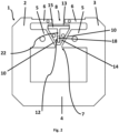
- a first place is located in the second yoke 4. Due to other mechanical limitations, such as mounting holes, edge 10 of a first air gap 7 etc. a final location has been determined where openings 9 are located, however, if redesigned, the openings 9 might be placed in other parts of the second yoke 4, as shown in fig. 1 .
- Other suitable place is located in a second magnetic part 14 of a movable armature 14, as shown in fig. 2 . It should be noted that both locations for permanent magnets may be used in the same circuit breaker mechanism.
- the core 1 has been designed such that it may be implemented in currently used circuit breaker mechanisms.
- a core 1 for a circuit breaker mechanism comprising a first limb 2, a second limb 3, a first yoke 4, a second yoke 5, a third yoke 6. Between the first limb 2 and the second limb 3 there are the first yoke 4, the second yoke 5 and the third yoke 6.
- the third yoke 6 has a smaller cross-section area then the second yoke 5.
- the second yoke 5 comprises a first air gap 7 and at least one opening 9, preferably at least one opening 9 is located near the first limb 2 and/or the second limb 3. Edges 10 of the first air gap 7 are tilted such that the first air gap 7 forms a trapezoid.
- the third yoke 6 comprises a second air gap 8.
- the at least one opening 9 has a rectangular shape. Such shape allows to use the permanent magnet 18 with a standard bar shape.
- the at least one opening 9 axis is perpendicular to a plane formed by the first limb 2 and the second limb 3.
- Such opening 9 enables an easier manufacturing process by providing easy access to the opening, even when the core 1 is placed in the circuit breaker mechanism.
- the movable armature 12 comprising a first magnetic part 13, a second magnetic part 14, a magnetic separator 15 made of a non-magnetic material, such as a paramagnetic material.
- a sliding mechanism 20 is configured for providing a sliding movement of the movable armature 12.
- the first magnetic part 13 has such a shape that it may adjoin to the third yoke 6 over the second air gap 8.
- the second magnetic part 14 has such a shape that it may be placed in the first air gap 7.
- the first magnetic part 13 is separated from the second magnetic part 14 with the magnetic separator 15.
- the bus bar 11 is placed in a window formed by the first limb 2, the second limb 3, the first yoke 4, and the second yoke 5.
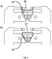
- the moveable armature 12 is configured such that it may move between a first position 16 and a second position 17, where in the first position 16 the first magnetic part 13 adjoins the third yoke 6 and there is a first gap between the second magnetic part 14 and the second yoke 5, and in the second position 17 there is a second gap between the first magnetic part 13 and the third yoke 6 and the second magnetic part 14 adjoins the second yoke 5, as shown in fig. 3 .
- the movable armature 12 when the current flowing through the bus bar 11 is lower than a threshold current, the movable armature 12 is configured such that it is in the first position 16. Such result may be achieved gravitationally or mechanically and the person skilled in the art will know how to achieve it.
- the circuit breaker mechanism works as follows.
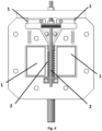
- the current flows through the bus bar 11 (or more bus bars 11 as shown on fig. 4 ), which generates a magnetic flux in the core 1.
- a magnetic flux runs through the first limb 2, the first yoke 3, the second limb 3 and it will split into the second yoke 5 and the third yoke 6. Since the movable armature 12 is in the first position 16, the first magnetic part 13 is closer to the third yoke 6, over the second air gap 8, than the second magnetic part 14 to the edges 10 of the first air gap 7 in the second yoke 5.
- both the first magnetic part 13 and the second magnetic part 14 acts as electromagnets being attracted to, respectively, the third yoke 6 and the second yoke 5.
- the magnetic flux also increases. Due to the fact that the third yoke 6 has a smaller cross section than the second yoke 5, the saturation of the third yoke 6 will happen faster and after that increase in the current running through the bus bar 11 will only increase the magnetic flux in the second yoke 5 which will increase the attraction force in the electromagnet made of the second magnetic part 14. In the high enough current the attraction force generated by the second magnetic part 14 will be greater than the attraction force generated by the first magnetic part 13 and the movable armature 12 will move to the second position 17 and further activate a switch - the switch and further mechanical and electrical circuits are not shown since those are known for the person skilled in the art.
- both magnetic fluxes running through the third yoke 6 and the second yoke 5 are separated between the first limb 2 and the second limb 3.
- the prior art circuit breaker mechanism will have a characteristic as shown on fig. 5 . It is apparent that the characteristic is symmetrical and the same values appears for the same current regardless of a direction of the current flowing through the bus bar 11.
- a first graph 23 shows a force acting on the movable armature 12 toward the first position 17.
- a second graph 24 shows a force acting on the movable armature 12 toward the second position 18.
- a third graph 25 shows a sum of the first graph 23 and the second graph 24. It may be seen that up to approx. 1500 A the sum has a positive value (more force toward the first position 17) and after that it quickly become more negative (more force towards the second position 18) which will cause the movable armature 12 to change position.
- the top line is a force generated by the first electromagnet made of the first magnetic part 13 and the third yoke 4.
- the bottom line is the force generated by the second electromagnet made of the second magnetic part 14 and the second yoke 5. It should be noted that the bottom line shows a negative force since it is pointing toward the opposite direction.
- the middle line is a sum of forces acting on the movable armature 12. It should be noted that up to approx. 1400 A forces are balanced and after that the force generated by the second electromagnet is greater which will result in movement of the movable armature 12 to the second position 17. It should be noted that it is an example and other values may be archived. It should also be noted that the force generated by a spring 21 is not discussed here and the spring 21 will be elaborated more hereinafter.
- the permanent magnet 18 is introduced in at least one place.
- fig. 1 it is shown that the permanent magnets 18 are placed in the second yoke 5, however it should be noted that one permanent magnets 18, or more than two, may be used.
- the permanent magnet 18 is located in the second magnetic part 14. Regardless of the variant the result is the same - the magnetic flux running though the second yoke 5 is weekend, in one direction, and boosted in the other direction. In such a case the asymmetrical characteristics, as shown on fig. 6 and 7 , are achieved - fig. 6 and 7 will be discussed more hereinafter.
- the circuit breaker mechanism according to the invention is a unidirectional circuit breaker mechanism.
- the other benefit is that an activation current may also be lowered. Additionally such solution may be used in the currently manufactured circuit breakers which is additionally beneficial.
- the core 1 as described previously is used in the circuit breaker mechanism.
- the at least one permanent magnet 18 is located in an opening 9 in the second yoke 5.
- one of the openings 9 is located near the first limb 2, and the other of the openings 9 is located near the second limb 3.
- placing the permanent magnet 18 in the opening is solution directed to the assembling of the circuit breaker mechanism rather than toward the core idea.
- Other solutions directed toward placing the permanent magnet 18 in designated place may be developed.
- the one solution proposed in this specification is directed toward the use of, in principle, the core 1 of the same general shape as previously and should not be treated as essential feature of this invention.
- each of the at least one permanent magnet 18 is placed such that a first magnetic pole point toward the first limb 2 and a second magnetic pole points towards the second limb 3. In this case a result will be better than in the case in which the first magnetic pole and the second magnetic pole are tilted with respect to the magnetic flux in the second yoke 5.
- the first magnetic part 13 is in a form of a bar.
- the second magnetic part 14 is in a form of a triangle or trapezoid block, however other shapes may be suitable. One may even consider the second magnetic part 14 in a bar shape, however proposed shape provides a greater cross section for the magnetic flux.
- the second magnetic part 14 comprises an additional opening 22 in which the permanent magnet 18 is placed.
- the permanent magnet 18 As previously mentioned other solutions directed toward placing the permanent magnet 18 in designated place may be developed.
- the one solution proposed in this specification is directed toward the use of, in principle, the second magnetic part 14 of the same general shape as previously and should not be treated as essential feature of this invention.
- opening 9 and the additional opening 22 both may have other shapes or may be a slit, as long as those structures enables the permanent magnet 18 to be placed in the designated place.
- the sliding mechanism 20 comprises a spring 21 configured such that the movable armature 12 is being forced toward the first position 16.
- the spring 21 is providing means for the movable armature 12 to be configured such that it is in the first position 16 when the current flowing through the bus bar 11 is lower than the threshold current.
- the second electromagnet generates the force that must be grater than the force generated by the first electromagnet and the spring 21.
- the spring 21 may be used to fine tune the circuit breaker mechanism so that the threshold current is higher. Other parameters may also be used for tuning the circuit breaker mechanism.
- Those parameters are: strength of the permanent magnet 18, the permanent magnet 18 size (a width and an area - the best results are achieved when the area of the permanent magnet 18 is as big as possible in relation to the cross section of the second yoke 5), as well as other geometrical parameters of both the first air gap 7, the second air gap 8, opening 9 and additional opening 22.
- the purpose of such ring 19 is that, during a change of the magnetic flux in the third yoke 6, eddy currents are generated in the ring 19 which generate another magnetic flux, in the opposite direction.
- the ring 19 causes that a rapid current changes will activate the circuit breaker mechanism faster due to lower magnetic flux in the third yoke 6 and thus lower force generated by the first electromagnet.
- Fig. 6 shows a diagram of forces in a circuit breaker mechanism with two magnets while fig. 7 shows a diagram of forces in a circuit breaker mechanism with one magnet, wherein in both fig. 6 and 7 X axis represents a current and the Y axis represents a force - if the force is greater than 0, then the movable armature 12 stays in the first position 16 and when the force is less than 0 then the movable armature 12 moves toward the second position 17.
- each graph on fig. 6 and 7 is a sum of forces in the same meaning as in the fig. 5 but in a modified circuit breaker.
- a fourth graph 26 shows a sum of forces acting on the movable armature 12 in the first position 17
- a fifth graph 27 shows a sum of forces acting on the movable armature 12 when the movable armature 12 is moved 0,2 mm toward the second position 18 from the first position 17
- a the sixth graph 28 shows a sum of forces acting on the movable armature 12 when the movable armature is in the second position 18.
- a seventh graph 29 shows a sum of forces acting on the movable armature 12 in the first position 17
- a eighth graph 30 shows a sum of forces acting on the movable armature 12 when the movable armature 12 is moved 0,3 mm toward the second position 18 from the first position 17
- a ninth graph 31 shows a sum of forces acting on the movable armature 12 when the movable armature 12 is in the second position 18.
- fourth graph 26 and seventh graph 29 shows a sum of forces acting on the movable armature 12 in the first position 17.
- the movable armature 12 is moving toward the second position 18 due to the negative sum of the forces.
- the sum of forces may be represented as in fifth graph 27 and eighth graph 30 - after even the smallest movement toward the second position 18 the first air gap 7 is getting smaller and the second air gap 8 is getting larger and thus the sum of forces become even more negative.
- the movable armature 12 is in the second position 18, as shown in sixth graph 28 and ninth graph 31 practically any positive current will generate enough flux to keep the movable armature 12 in the second position 18.
- the movable armature 12 will go back to the first position 17 after the current will reach 0A.
Landscapes
- Physics & Mathematics (AREA)
- Electromagnetism (AREA)
- Breakers (AREA)
Abstract
The invention relates to a core for a circuit breaker mechanism and a circuit breaker mechanism designed for a high current bus bars.
A core for a circuit breaker mechanism comprising: a first limb (2), a second limb (3), a first yoke (4), a second yoke (5), a third yoke (6); wherein between the first limb (2) and the second limb (3) there are the first yoke (4), the second yoke (5) and the third yoke (6), wherein the third yoke (6) has a smaller cross-section area then the second yoke (5), wherein the second yoke (5) comprises a first air gap (7) and at least one opening (9), where edges (10) of the first air gap (7) are tilted such that the first air gap (7) forms a trapezoid, and wherein the third yoke (6) comprises a second air gap (8).
Description
- The invention relates to a core for a circuit breaker mechanism and a circuit breaker mechanism designed for a high current bus bars.
DocumentEP2431991A1 discloses an electromechanical release mechanism to be used in a circuit interrupting device such as a circuit breaker mechanism and in particular in a DC (direct current) circuit interrupting device. The object of the invention shown in this document is a release mechanism for a circuit interrupting device comprising a ferromagnetic main frame through which can flow a current and a ferromagnetic movable core designed to be translated in an opening of the main frame between a first position in which the circuit interrupting device remains closed and a second position in which the circuit interrupting device is opened. The said release mechanism is designed to use the flux generated inside the main frame by the current flowing through it to displace the movable core between its first and second positions. The release mechanism further comprises at least two permanent magnets mounted on the main frame on each side of the opening and relatively oriented so as to generate a unidirectional unique magnetic flux inside the main frame and the movable core, the said magnetic flux creating a first force on the movable core that tends to maintain it in its first position. The permanent magnets, the movable core and the main frame are further conformed so that the movable core is displaced from its first position into its second position when a first current flowing through the main frame and generating a first flux inside the main frame and the movable core in the same direction as the magnetic flux exceeds a first limit value or when a second current flowing through the main frame and generating a second flux inside the main frame and the movable core in the direction opposite to the magnetic flux exceeds a second limit value, the said second limit value being different than the first limit value. - A first embodiment of the present invention is a core for a circuit breaker mechanism. The core comprising a first limb, a second limb, a first yoke, a second yoke, a third yoke. Between the first limb and the second limb there are the first yoke, the second yoke and the third yoke. The third yoke has a smaller cross-section area then the second yoke. The second yoke comprises a first air gap and at least one opening. Edges of the first air gap are tilted such that the first air gap forms a trapezoid. The third yoke comprises a second air gap.
- Preferably the at least one opening is located near the first limb and/or the second limb.
- Preferably there are two openings, wherein preferably one of the openings is located near the first limb, and where the other openings is located near the second limb.
- Preferably the at least one opening has a rectangular shape.
- Preferably the at least one opening axis is perpendicular to a plane formed by the first limb and the second limb.
- A second embodiment of the present invention is a circuit breaker mechanism. The circuit breaker mechanism comprising a core, a movable armature and a bus bar. The core comprising a first limb, a second limb, a first yoke, a second yoke, a third yoke. Between the first limb and the second limb there are the first yoke, the second yoke and the third yoke. The third yoke has a smaller cross-section area then the second yoke. The second yoke comprises a first air gap. Edges of the first air gap are tilted such that the first air gap forms a trapezoid. The third yoke comprises a second air gap. The movable armature comprising a first magnetic part, a second magnetic part, a magnetic separator made of a paramagnetic material, a sliding mechanism configured for providing a sliding movement of the movable armature. The first magnetic part has such a shape that it may adjoin to the third yoke over the second air gap. The second magnetic part has such a shape that it may be placed in the first air gap. The first magnetic part is separated from the second magnetic part with the magnetic separator. The bus bar is placed in a window formed by the first limb, the second limb, the first yoke, and the second yoke. The moveable armature is configured such that it may move between a first position and a second position, where in the first position the first magnetic part adjoins the third yoke and there is a first gap between the second magnetic part and the second yoke, and in the second position there is a second gap between the first magnetic part and the third yoke and the second magnetic part adjoins the second yoke. When the current flowing through the bus bar is lower than a threshold current, the movable armature is configured such that it is in the first position. In the second yoke and/or the second magnetic part there is at least one permanent magnet, wherein each of the at least one permanent magnet are placed such, that a magnetic flux in one direction is amplified and in other direction is attenuate.
- Preferably the core is as described in claims 1-5, wherein the at least one permanent magnet is located in an opening in the second yoke, preferably there are two permanent magnets and two openings in the second yoke, in each opening there is one permanent magnet.
- Preferably each of the at least one permanent magnet is placed such that a first magnetic pole point toward the first limb and a second magnetic pole points towards the second limb.
- Preferably the first magnetic part is in a form of a bar.
- Preferably the second magnetic part is in a form of a triangle or trapezoid block.
- Preferably the second magnetic part comprises an additional opening in which the permanent magnet is placed.
- Preferably the sliding mechanism comprises a spring configured such that the movable armature is being forced toward the first position.
- Preferably the at least one ring made of a diamagnetic metal, preferably copper, is placed on the third yoke.
- It is the purpose of the present invention to provide circuit breaker mechanism designed for a high current bus bars with an asymmetrical characteristics, which practically acts as a single current direction circuit breaker mechanism. A design according to the invention further allows to lower the activation current of the circuit breaker mechanism and it is suitable to use in a currently used circuit breaker mechanisms.
- Preferred embodiments of the invention are described below by way of example with reference to the following drawings, where:
- Fig. 1
- shows a simplified view of a first embodiment where two permanent magnets are used,
- Fig. 2
- shows a simplified view of a first embodiment where one permanent magnet is used,
- Fig. 3
- shows two positions of a movable armature,
- Fig. 4
- shows a circuit breaker mechanism with all necessary elements,
- Fig. 5
- shows a diagram of forces in a prior art circuit breaker mechanism,
- Fig. 6
- shows a diagram of forces in a circuit breaker mechanism with two magnets,
- Fig. 7
- shows a diagram of forces in a circuit breaker mechanism with one magnet.
- The general idea behind this invention is to provide at least one magnet such that the it will either reduce a magnetic flux in a
second yoke 4 or the magnetic flux will be increased. It will depend on a current flow direction in a bus bar 11. - During tests it appears that two locations for magnets are suitable. A first place is located in the
second yoke 4. Due to other mechanical limitations, such as mounting holes,edge 10 of afirst air gap 7 etc. a final location has been determined whereopenings 9 are located, however, if redesigned, theopenings 9 might be placed in other parts of thesecond yoke 4, as shown infig. 1 . Other suitable place is located in a secondmagnetic part 14 of amovable armature 14, as shown infig. 2 . It should be noted that both locations for permanent magnets may be used in the same circuit breaker mechanism. - For the first embodiment the
core 1 has been designed such that it may be implemented in currently used circuit breaker mechanisms. Acore 1 for a circuit breaker mechanism comprising afirst limb 2, asecond limb 3, afirst yoke 4, asecond yoke 5, athird yoke 6. Between thefirst limb 2 and thesecond limb 3 there are thefirst yoke 4, thesecond yoke 5 and thethird yoke 6. Thethird yoke 6 has a smaller cross-section area then thesecond yoke 5. Thesecond yoke 5 comprises afirst air gap 7 and at least oneopening 9, preferably at least oneopening 9 is located near thefirst limb 2 and/or thesecond limb 3.Edges 10 of thefirst air gap 7 are tilted such that thefirst air gap 7 forms a trapezoid. Thethird yoke 6 comprises asecond air gap 8. - In yet another example there are two
openings 9, wherein preferably one of theopenings 9 is located near thefirst limb 2, and where theother openings 9 is located near thesecond limb 3. Insuch core 1 two smallerpermanent magnets 18 may be used. - In another example the at least one
opening 9 has a rectangular shape. Such shape allows to use thepermanent magnet 18 with a standard bar shape. - In yet another example the at least one opening 9 axis is perpendicular to a plane formed by the
first limb 2 and thesecond limb 3.Such opening 9 enables an easier manufacturing process by providing easy access to the opening, even when thecore 1 is placed in the circuit breaker mechanism. - In general a circuit breaker mechanism is proposed which comprises a
core 1, amovable armature 12 and a bus bar 11. Thecore 1 comprising afirst limb 2, asecond limb 3, afirst yoke 4, asecond yoke 5, and athird yoke 6. Between thefirst limb 2 and thesecond limb 3 there are thefirst yoke 4, thesecond yoke 5 and thethird yoke 6. Thethird yoke 6 has a smaller cross-section area then thesecond yoke 5. Thesecond yoke 5 comprises afirst air gap 7, where edges 10 of thefirst air gap 7 are tilted such that thefirst air gap 7 forms a trapezoid. Thethird yoke 6 comprises asecond air gap 8. Themovable armature 12 comprising a firstmagnetic part 13, a secondmagnetic part 14, a magnetic separator 15 made of a non-magnetic material, such as a paramagnetic material. A sliding mechanism 20 is configured for providing a sliding movement of themovable armature 12. The firstmagnetic part 13 has such a shape that it may adjoin to thethird yoke 6 over thesecond air gap 8. The secondmagnetic part 14 has such a shape that it may be placed in thefirst air gap 7. The firstmagnetic part 13 is separated from the secondmagnetic part 14 with the magnetic separator 15. The bus bar 11 is placed in a window formed by thefirst limb 2, thesecond limb 3, thefirst yoke 4, and thesecond yoke 5. Themoveable armature 12 is configured such that it may move between afirst position 16 and asecond position 17, where in thefirst position 16 the firstmagnetic part 13 adjoins thethird yoke 6 and there is a first gap between the secondmagnetic part 14 and thesecond yoke 5, and in thesecond position 17 there is a second gap between the firstmagnetic part 13 and thethird yoke 6 and the secondmagnetic part 14 adjoins thesecond yoke 5, as shown infig. 3 . In thesecond yoke 5 and/or the secondmagnetic part 14 there is at least onepermanent magnet 18, wherein each of the at least onepermanent magnet 18 are placed such, that a magnetic flux in one direction is amplified and in other direction is attenuated. It should be noted that, when the current flowing through the bus bar 11 is lower than a threshold current, themovable armature 12 is configured such that it is in thefirst position 16. Such result may be achieved gravitationally or mechanically and the person skilled in the art will know how to achieve it. - In a
fig. 4 all necessary parts of the circuit breaker mechanisms are shown, especially bus bars 11 and mechanical, such as sliding mechanism 20 and spring 21. Such parts are however typical in already used circuits breakers and, for a clarity of disclosure, are not shown infig. 1-3 . - The circuit breaker mechanism according to the invention works as follows. The current flows through the bus bar 11 (or more bus bars 11 as shown on
fig. 4 ), which generates a magnetic flux in thecore 1. For now, for a purpose of the explanation, it is assumed that there are no permanent magnets and basically a prior art circuit breaker mechanism is described. In such a case a magnetic flux runs through thefirst limb 2, thefirst yoke 3, thesecond limb 3 and it will split into thesecond yoke 5 and thethird yoke 6. Since themovable armature 12 is in thefirst position 16, the firstmagnetic part 13 is closer to thethird yoke 6, over thesecond air gap 8, than the secondmagnetic part 14 to theedges 10 of thefirst air gap 7 in thesecond yoke 5. - Due to the magnetic flux running through the
second yoke 5 and thethird yoke 6 both the firstmagnetic part 13 and the secondmagnetic part 14 acts as electromagnets being attracted to, respectively, thethird yoke 6 and thesecond yoke 5. - In the case of an increasing current running through the bus bar 11 the magnetic flux also increases. Due to the fact that the
third yoke 6 has a smaller cross section than thesecond yoke 5, the saturation of thethird yoke 6 will happen faster and after that increase in the current running through the bus bar 11 will only increase the magnetic flux in thesecond yoke 5 which will increase the attraction force in the electromagnet made of the secondmagnetic part 14. In the high enough current the attraction force generated by the secondmagnetic part 14 will be greater than the attraction force generated by the firstmagnetic part 13 and themovable armature 12 will move to thesecond position 17 and further activate a switch - the switch and further mechanical and electrical circuits are not shown since those are known for the person skilled in the art. It should also be noted that due to the magnetic separator 15, made of a non-magnetic material such as a plastic, both magnetic fluxes running through thethird yoke 6 and thesecond yoke 5 are separated between thefirst limb 2 and thesecond limb 3. - The prior art circuit breaker mechanism will have a characteristic as shown on
fig. 5 . It is apparent that the characteristic is symmetrical and the same values appears for the same current regardless of a direction of the current flowing through the bus bar 11. Afirst graph 23 shows a force acting on themovable armature 12 toward thefirst position 17. Asecond graph 24 shows a force acting on themovable armature 12 toward thesecond position 18. Athird graph 25 shows a sum of thefirst graph 23 and thesecond graph 24. It may be seen that up to approx. 1500 A the sum has a positive value (more force toward the first position 17) and after that it quickly become more negative (more force towards the second position 18) which will cause themovable armature 12 to change position. - The top line is a force generated by the first electromagnet made of the first
magnetic part 13 and thethird yoke 4. The bottom line is the force generated by the second electromagnet made of the secondmagnetic part 14 and thesecond yoke 5. It should be noted that the bottom line shows a negative force since it is pointing toward the opposite direction. The middle line is a sum of forces acting on themovable armature 12. It should be noted that up to approx. 1400 A forces are balanced and after that the force generated by the second electromagnet is greater which will result in movement of themovable armature 12 to thesecond position 17. It should be noted that it is an example and other values may be archived. It should also be noted that the force generated by a spring 21 is not discussed here and the spring 21 will be elaborated more hereinafter. - In the disclosed invention the
permanent magnet 18 is introduced in at least one place. Onfig. 1 it is shown that thepermanent magnets 18 are placed in thesecond yoke 5, however it should be noted that onepermanent magnets 18, or more than two, may be used. In the other embodiment shown onfig. 2 thepermanent magnet 18 is located in the secondmagnetic part 14. Regardless of the variant the result is the same - the magnetic flux running though thesecond yoke 5 is weekend, in one direction, and boosted in the other direction. In such a case the asymmetrical characteristics, as shown onfig. 6 and7 , are achieved -fig. 6 and7 will be discussed more hereinafter. - The first consequence of the use of the
permanent magnets 18 is that, in practical application, the circuit breaker mechanism according to the invention is a unidirectional circuit breaker mechanism. The other benefit is that an activation current may also be lowered. Additionally such solution may be used in the currently manufactured circuit breakers which is additionally beneficial. - In the preferred example the
core 1 as described previously is used in the circuit breaker mechanism. The at least onepermanent magnet 18 is located in anopening 9 in thesecond yoke 5. Preferably there are twopermanent magnets 18 and twoopenings 9 in thesecond yoke 5, in eachopening 9 there is onepermanent magnet 18. As shown onfig. 1 one of theopenings 9 is located near thefirst limb 2, and the other of theopenings 9 is located near thesecond limb 3. It should be however noted that placing thepermanent magnet 18 in the opening is solution directed to the assembling of the circuit breaker mechanism rather than toward the core idea. Other solutions directed toward placing thepermanent magnet 18 in designated place may be developed. The one solution proposed in this specification is directed toward the use of, in principle, thecore 1 of the same general shape as previously and should not be treated as essential feature of this invention. - In yet another preferred example each of the at least one
permanent magnet 18 is placed such that a first magnetic pole point toward thefirst limb 2 and a second magnetic pole points towards thesecond limb 3. In this case a result will be better than in the case in which the first magnetic pole and the second magnetic pole are tilted with respect to the magnetic flux in thesecond yoke 5. Some variations of thepermanent magnets 18 orientation are allowable, however, as stated hereinbefore, the magnetic flux in one direction must be amplified and in other direction must be attenuate. - In another example the first
magnetic part 13 is in a form of a bar. - In another example the second
magnetic part 14 is in a form of a triangle or trapezoid block, however other shapes may be suitable. One may even consider the secondmagnetic part 14 in a bar shape, however proposed shape provides a greater cross section for the magnetic flux. - In another example the second
magnetic part 14 comprises anadditional opening 22 in which thepermanent magnet 18 is placed. As previously mentioned other solutions directed toward placing thepermanent magnet 18 in designated place may be developed. The one solution proposed in this specification is directed toward the use of, in principle, the secondmagnetic part 14 of the same general shape as previously and should not be treated as essential feature of this invention. - It should be understood that in the case of the
opening 9 and theadditional opening 22 both may have other shapes or may be a slit, as long as those structures enables thepermanent magnet 18 to be placed in the designated place. - In another example the sliding mechanism 20 comprises a spring 21 configured such that the
movable armature 12 is being forced toward thefirst position 16. The spring 21 is providing means for themovable armature 12 to be configured such that it is in thefirst position 16 when the current flowing through the bus bar 11 is lower than the threshold current. On the other hand the second electromagnet generates the force that must be grater than the force generated by the first electromagnet and the spring 21. The spring 21 may be used to fine tune the circuit breaker mechanism so that the threshold current is higher. Other parameters may also be used for tuning the circuit breaker mechanism. Those parameters are: strength of thepermanent magnet 18, thepermanent magnet 18 size (a width and an area - the best results are achieved when the area of thepermanent magnet 18 is as big as possible in relation to the cross section of the second yoke 5), as well as other geometrical parameters of both thefirst air gap 7, thesecond air gap 8,opening 9 andadditional opening 22. - In yet another example at least one ring 19 made of a diamagnetic metal, preferably copper, is placed on the
third yoke 6. The purpose of such ring 19 is that, during a change of the magnetic flux in thethird yoke 6, eddy currents are generated in the ring 19 which generate another magnetic flux, in the opposite direction. The ring 19 causes that a rapid current changes will activate the circuit breaker mechanism faster due to lower magnetic flux in thethird yoke 6 and thus lower force generated by the first electromagnet. -
Fig. 6 shows a diagram of forces in a circuit breaker mechanism with two magnets whilefig. 7 shows a diagram of forces in a circuit breaker mechanism with one magnet, wherein in bothfig. 6 and7 X axis represents a current and the Y axis represents a force - if the force is greater than 0, then themovable armature 12 stays in thefirst position 16 and when the force is less than 0 then themovable armature 12 moves toward thesecond position 17. The person skilled in the art will know that when themovable armature 12 moves toward thesecond position 17 the force acting on the moveable armature also increases due to the fact thefirst air gap 7 decreases, which results in more "negative" force, while thesecond air gap 8 increases which results in less "positive" force. It should be noted that each graph onfig. 6 and7 is a sum of forces in the same meaning as in thefig. 5 but in a modified circuit breaker. - Abovementioned diagrams should be compared to the prior art circuits as shown in
fig. 5 . It should be noted that the diagram shown infig. 6 and7 are not symmetrical. Infig. 6 diagram reaches 0, that is a point of imbalance, at aprox. 1500A and -7000A. Infig. 7 diagram reaches 0 at aprox. 1350A and -6000A. It should be noted that the value 1350A is lower than typical 1500A - the present invention may also be applied to lower a current needed to activate the circuit breaker. - In
fig. 6 afourth graph 26 shows a sum of forces acting on themovable armature 12 in thefirst position 17, afifth graph 27 shows a sum of forces acting on themovable armature 12 when themovable armature 12 is moved 0,2 mm toward thesecond position 18 from thefirst position 17, a thesixth graph 28 shows a sum of forces acting on themovable armature 12 when the movable armature is in thesecond position 18. - In
fig. 7 aseventh graph 29 shows a sum of forces acting on themovable armature 12 in thefirst position 17, aeighth graph 30 shows a sum of forces acting on themovable armature 12 when themovable armature 12 is moved 0,3 mm toward thesecond position 18 from thefirst position 17, and aninth graph 31 shows a sum of forces acting on themovable armature 12 when themovable armature 12 is in thesecond position 18. - As it may be seen in both
fig. 6 and7 fourth graph 26 andseventh graph 29 shows a sum of forces acting on themovable armature 12 in thefirst position 17. After the current reaches a threshold value themovable armature 12 is moving toward thesecond position 18 due to the negative sum of the forces. At the beginning the sum of forces may be represented as infifth graph 27 and eighth graph 30 - after even the smallest movement toward thesecond position 18 thefirst air gap 7 is getting smaller and thesecond air gap 8 is getting larger and thus the sum of forces become even more negative. After themovable armature 12 is in thesecond position 18, as shown insixth graph 28 andninth graph 31 practically any positive current will generate enough flux to keep themovable armature 12 in thesecond position 18. Themovable armature 12 will go back to thefirst position 17 after the current will reach 0A. - 1
- core
- 2
- first limb
- 3
- second limb
- 4
- first yoke
- 5
- second yoke
- 6
- third yoke
- 7
- first air gap
- 8
- second air gap
- 9
- opening
- 10
- edge of the first air gap
- 11
- bus bar
- 12
- movable armature
- 13
- first magnetic part
- 14
- second magnetic part
- 15
- magnetic separator
- 16
- first position of the movable armature
- 17
- second position of the movable armature
- 18
- permanent magnet
- 19
- ring
- 20
- sliding mechanism
- 21
- spring
- 22
- additional opening
Claims (13)
- A core for a circuit breaker mechanism comprising:a first limb (2),a second limb (3),a first yoke (4),a second yoke (5),a third yoke (6);wherein between the first limb (2) and the second limb (3) there are the first yoke (4), the second yoke (5) and the third yoke (6), whereinthe third yoke (6) has a smaller cross-section area then the second yoke (5),wherein the second yoke (5) comprises a first air gap (7) and at least one opening (9), where edges (10) of the first air gap (7) are tilted such that the first air gap (7) forms a trapezoid, andwherein the third yoke (6) comprises a second air gap (8).
- The core according to claim 1, characterized in that the at least one opening (9) is located near the first limb (2) and/or the second limb (3).
- The core according to claim 1 or 2, characterized in that there are two openings (9), wherein preferably one of the openings (9) is located near the first limb (2), and where the other openings (9) is located near the second limb (3).
- The core according to anyone of the previous claims, characterized in that the at least one opening (9) has a rectangular shape.
- The core according to anyone of the previous claims, characterized in that the at least one opening (9) axis is perpendicular to a plane formed by the first limb (2) and the second limb (3).
- A circuit breaker mechanism comprising a core (1), a movable armature (12) and a bus bar (11), wherein the core (1) comprising:a first limb (2),a second limb (3),a first yoke (4),a second yoke (5),a third yoke (6);wherein between the first limb (2) and the second limb (3) there are the first yoke (4), the second yoke (5) and the third yoke (6), whereinthe third yoke (6) has a smaller cross-section area then the second yoke (5),wherein the second yoke (5) comprises a first air gap (7), where edges (10) of the first air gap (7) are tilted such that the first air gap (7) forms a trapezoid, andwherein the third yoke (6) comprises a second air gap (8),wherein the movable armature (12) comprising:a first magnetic part (13),a second magnetic part (14),a magnetic separator (15) made of a paramagnetic material,a sliding mechanism (20) configured for providing a sliding movement of the movable armature (12);wherein the first magnetic part (13) has such a shape that it may adjoin to the third yoke (6) over the second air gap (8),wherein the second magnetic part (14) has such a shape that it may be placed in the first air gap (7),wherein the first magnetic part (13) is separated from the second magnetic part (14) with the magnetic separator (15),the bus bar (11) is placed in a window formed by the first limb (2), the second limb (3), the first yoke (4), and the second yoke (5),wherein the moveable armature (12) is configured such that it may move between a first position (16) and a second position (17), where in the first position (16) the first magnetic part (13) adjoins the third yoke (6) and there is a first gap between the second magnetic part (14) and the second yoke (5), and in the second position (17) there is a second gap between the first magnetic part (13) and the third yoke (6) and the second magnetic part (14) adjoins the second yoke (5),wherein, when the current flowing through the bus bar (11) is lower than a threshold current, the movable armature (12) is configured such that it is in the first position (16),wherein in the second yoke (5) and/or the second magnetic part (14) there is at least one permanent magnet (18), wherein each of the at least one permanent magnet (18) are placed such, that a magnetic flux in one direction is amplified and in other direction is attenuate.
- The circuit breaker mechanism according to claim 6, characterized in that the core (1) is as described in claims 1-5, wherein the at least one permanent magnet (18) is located in an opening (9) in the second yoke (5), preferably there are two permanent magnets (18) and two openings (9) in the second yoke (5), in each opening (9) there is one permanent magnet (18).
- The circuit breaker mechanism according to claim 6 or 7, characterized in that each of the at least one permanent magnet (18) is placed such that a first magnetic pole point toward the first limb (2) and a second magnetic pole points towards the second limb (3).
- The circuit breaker mechanism according to anyone of claims 6-8, characterized in that the first magnetic part (13) is in a form of a bar.
- The circuit breaker mechanism according to anyone of claims 6-9, characterized in that the second magnetic part (14) is in a form of a triangle or trapezoid block.
- The circuit breaker mechanism according to anyone of claims 6-10, characterized in that the second magnetic part (14) comprises an additional opening (22) in which the permanent magnet (18) is placed.
- The circuit breaker mechanism according to anyone of claims 6-11, characterized in that the sliding mechanism (20) comprises a spring (21) configured such that the movable armature (12) is being forced toward the first position (16).
- The circuit breaker mechanism according to anyone of claims 6-12, characterized in that the at least one ring (19) made of a diamagnetic metal, preferably copper, is placed on the third yoke (6).
Priority Applications (1)
| Application Number | Priority Date | Filing Date | Title |
|---|---|---|---|
| EP23213227.4A EP4564394A1 (en) | 2023-11-30 | 2023-11-30 | Core for circuit breaker mechanism and circuit breaker mechanism |
Applications Claiming Priority (1)
| Application Number | Priority Date | Filing Date | Title |
|---|---|---|---|
| EP23213227.4A EP4564394A1 (en) | 2023-11-30 | 2023-11-30 | Core for circuit breaker mechanism and circuit breaker mechanism |
Publications (1)
| Publication Number | Publication Date |
|---|---|
| EP4564394A1 true EP4564394A1 (en) | 2025-06-04 |
Family
ID=89029857
Family Applications (1)
| Application Number | Title | Priority Date | Filing Date |
|---|---|---|---|
| EP23213227.4A Pending EP4564394A1 (en) | 2023-11-30 | 2023-11-30 | Core for circuit breaker mechanism and circuit breaker mechanism |
Country Status (1)
| Country | Link |
|---|---|
| EP (1) | EP4564394A1 (en) |
Citations (4)
| Publication number | Priority date | Publication date | Assignee | Title |
|---|---|---|---|---|
| DE19715114A1 (en) * | 1997-04-11 | 1998-10-22 | Aeg Niederspannungstech Gmbh | Overcurrent trigger for fast DC switch |
| EP2431991A1 (en) | 2010-09-20 | 2012-03-21 | Sécheron SA | Release mechanism for circuit interrupting device |
| CN113161210A (en) * | 2021-04-19 | 2021-07-23 | 武汉长海电气科技开发有限公司 | Double-magnetic-circuit heavy-current release of circuit breaker |
| EP3971933A1 (en) * | 2019-05-16 | 2022-03-23 | Mitsubishi Electric Corporation | Overcurrent tripping device, and circuit breaker in which overcurrent tripping device is used |
-
2023
- 2023-11-30 EP EP23213227.4A patent/EP4564394A1/en active Pending
Patent Citations (4)
| Publication number | Priority date | Publication date | Assignee | Title |
|---|---|---|---|---|
| DE19715114A1 (en) * | 1997-04-11 | 1998-10-22 | Aeg Niederspannungstech Gmbh | Overcurrent trigger for fast DC switch |
| EP2431991A1 (en) | 2010-09-20 | 2012-03-21 | Sécheron SA | Release mechanism for circuit interrupting device |
| EP3971933A1 (en) * | 2019-05-16 | 2022-03-23 | Mitsubishi Electric Corporation | Overcurrent tripping device, and circuit breaker in which overcurrent tripping device is used |
| CN113161210A (en) * | 2021-04-19 | 2021-07-23 | 武汉长海电气科技开发有限公司 | Double-magnetic-circuit heavy-current release of circuit breaker |
Similar Documents
| Publication | Publication Date | Title |
|---|---|---|
| EP2472539B1 (en) | Electromagnetic relay | |
| KR100568906B1 (en) | Electromagnetic actuator | |
| EP0871192B1 (en) | Magnetic actuator | |
| EP1490884B1 (en) | Resettable switching device | |
| KR101362009B1 (en) | Hybrid electromagnetic actuator | |
| CN103650089B (en) | Electromagnetic operating device and employ the opening and closing device of this device | |
| JPH01225025A (en) | Electromagnetic tripper | |
| EP2434503B1 (en) | Magnetic actuator with a non-magnetic insert | |
| EP4564394A1 (en) | Core for circuit breaker mechanism and circuit breaker mechanism | |
| JP7380455B2 (en) | electromagnetic relay | |
| US20020171519A1 (en) | Clapper-type electromagnet assembly having v-shaped air gap for use in a circuit breaker trip unit | |
| US3673529A (en) | Magnetic actuator | |
| JP7374173B2 (en) | Solenoid assembly with reduced release time | |
| JP4975319B2 (en) | Vacuum circuit breaker | |
| US5631614A (en) | Magnetic self-latching electric contact | |
| HU215878B (en) | Electrical circuit breaker with electromagnetic actuator for high ratings | |
| RU2795269C1 (en) | Polarized high-speed electromagnet | |
| CN109716471B (en) | Low-voltage switchgear with electromagnetic contact load support | |
| KR102726585B1 (en) | Electromagnetic actuator and electrical switching unit including this actuator | |
| JPH04312733A (en) | Electromagnetic trip device for circuit breaker | |
| CN101523525A (en) | Electromagnet device | |
| EP3059749A1 (en) | Circuit breaker including current path geometries that increase contact self-popping level | |
| JP2006120917A (en) | Electromagnetic actuator | |
| JPH0223965B2 (en) | ||
| JPS63156305A (en) | Dash-pot type electromagnet |
Legal Events
| Date | Code | Title | Description |
|---|---|---|---|
| STAA | Information on the status of an ep patent application or granted ep patent |
Free format text: STATUS: UNKNOWN |
|
| PUAI | Public reference made under article 153(3) epc to a published international application that has entered the european phase |
Free format text: ORIGINAL CODE: 0009012 |
|
| STAA | Information on the status of an ep patent application or granted ep patent |
Free format text: STATUS: THE APPLICATION HAS BEEN PUBLISHED |
|
| AK | Designated contracting states |
Kind code of ref document: A1 Designated state(s): AL AT BE BG CH CY CZ DE DK EE ES FI FR GB GR HR HU IE IS IT LI LT LU LV MC ME MK MT NL NO PL PT RO RS SE SI SK SM TR |
|
| STAA | Information on the status of an ep patent application or granted ep patent |
Free format text: STATUS: REQUEST FOR EXAMINATION WAS MADE |
|
| 17P | Request for examination filed |
Effective date: 20251128 |