EP4564315A1 - Lidar based road condition estimation for passenger vehicles - Google Patents
Lidar based road condition estimation for passenger vehicles Download PDFInfo
- Publication number
- EP4564315A1 EP4564315A1 EP23213120.1A EP23213120A EP4564315A1 EP 4564315 A1 EP4564315 A1 EP 4564315A1 EP 23213120 A EP23213120 A EP 23213120A EP 4564315 A1 EP4564315 A1 EP 4564315A1
- Authority
- EP
- European Patent Office
- Prior art keywords
- road
- vehicle
- data points
- data
- condition
- Prior art date
- Legal status (The legal status is an assumption and is not a legal conclusion. Google has not performed a legal analysis and makes no representation as to the accuracy of the status listed.)
- Pending
Links
Images



Classifications
-
- B—PERFORMING OPERATIONS; TRANSPORTING
- B60—VEHICLES IN GENERAL
- B60W—CONJOINT CONTROL OF VEHICLE SUB-UNITS OF DIFFERENT TYPE OR DIFFERENT FUNCTION; CONTROL SYSTEMS SPECIALLY ADAPTED FOR HYBRID VEHICLES; ROAD VEHICLE DRIVE CONTROL SYSTEMS FOR PURPOSES NOT RELATED TO THE CONTROL OF A PARTICULAR SUB-UNIT
- B60W40/00—Estimation or calculation of non-directly measurable driving parameters for road vehicle drive control systems not related to the control of a particular sub unit, e.g. by using mathematical models
- B60W40/02—Estimation or calculation of non-directly measurable driving parameters for road vehicle drive control systems not related to the control of a particular sub unit, e.g. by using mathematical models related to ambient conditions
- B60W40/06—Road conditions
-
- G—PHYSICS
- G06—COMPUTING OR CALCULATING; COUNTING
- G06V—IMAGE OR VIDEO RECOGNITION OR UNDERSTANDING
- G06V20/00—Scenes; Scene-specific elements
- G06V20/50—Context or environment of the image
- G06V20/56—Context or environment of the image exterior to a vehicle by using sensors mounted on the vehicle
- G06V20/588—Recognition of the road, e.g. of lane markings; Recognition of the vehicle driving pattern in relation to the road
-
- B—PERFORMING OPERATIONS; TRANSPORTING
- B60—VEHICLES IN GENERAL
- B60W—CONJOINT CONTROL OF VEHICLE SUB-UNITS OF DIFFERENT TYPE OR DIFFERENT FUNCTION; CONTROL SYSTEMS SPECIALLY ADAPTED FOR HYBRID VEHICLES; ROAD VEHICLE DRIVE CONTROL SYSTEMS FOR PURPOSES NOT RELATED TO THE CONTROL OF A PARTICULAR SUB-UNIT
- B60W10/00—Conjoint control of vehicle sub-units of different type or different function
- B60W10/20—Conjoint control of vehicle sub-units of different type or different function including control of steering systems
-
- B—PERFORMING OPERATIONS; TRANSPORTING
- B60—VEHICLES IN GENERAL
- B60W—CONJOINT CONTROL OF VEHICLE SUB-UNITS OF DIFFERENT TYPE OR DIFFERENT FUNCTION; CONTROL SYSTEMS SPECIALLY ADAPTED FOR HYBRID VEHICLES; ROAD VEHICLE DRIVE CONTROL SYSTEMS FOR PURPOSES NOT RELATED TO THE CONTROL OF A PARTICULAR SUB-UNIT
- B60W10/00—Conjoint control of vehicle sub-units of different type or different function
- B60W10/22—Conjoint control of vehicle sub-units of different type or different function including control of suspension systems
-
- B—PERFORMING OPERATIONS; TRANSPORTING
- B60—VEHICLES IN GENERAL
- B60W—CONJOINT CONTROL OF VEHICLE SUB-UNITS OF DIFFERENT TYPE OR DIFFERENT FUNCTION; CONTROL SYSTEMS SPECIALLY ADAPTED FOR HYBRID VEHICLES; ROAD VEHICLE DRIVE CONTROL SYSTEMS FOR PURPOSES NOT RELATED TO THE CONTROL OF A PARTICULAR SUB-UNIT
- B60W30/00—Purposes of road vehicle drive control systems not related to the control of a particular sub-unit, e.g. of systems using conjoint control of vehicle sub-units
- B60W30/14—Adaptive cruise control
- B60W30/143—Speed control
-
- B—PERFORMING OPERATIONS; TRANSPORTING
- B60—VEHICLES IN GENERAL
- B60W—CONJOINT CONTROL OF VEHICLE SUB-UNITS OF DIFFERENT TYPE OR DIFFERENT FUNCTION; CONTROL SYSTEMS SPECIALLY ADAPTED FOR HYBRID VEHICLES; ROAD VEHICLE DRIVE CONTROL SYSTEMS FOR PURPOSES NOT RELATED TO THE CONTROL OF A PARTICULAR SUB-UNIT
- B60W30/00—Purposes of road vehicle drive control systems not related to the control of a particular sub-unit, e.g. of systems using conjoint control of vehicle sub-units
- B60W30/18—Propelling the vehicle
- B60W30/18009—Propelling the vehicle related to particular drive situations
- B60W30/18109—Braking
- B60W30/18127—Regenerative braking
-
- B—PERFORMING OPERATIONS; TRANSPORTING
- B60—VEHICLES IN GENERAL
- B60W—CONJOINT CONTROL OF VEHICLE SUB-UNITS OF DIFFERENT TYPE OR DIFFERENT FUNCTION; CONTROL SYSTEMS SPECIALLY ADAPTED FOR HYBRID VEHICLES; ROAD VEHICLE DRIVE CONTROL SYSTEMS FOR PURPOSES NOT RELATED TO THE CONTROL OF A PARTICULAR SUB-UNIT
- B60W40/00—Estimation or calculation of non-directly measurable driving parameters for road vehicle drive control systems not related to the control of a particular sub unit, e.g. by using mathematical models
- B60W40/12—Estimation or calculation of non-directly measurable driving parameters for road vehicle drive control systems not related to the control of a particular sub unit, e.g. by using mathematical models related to parameters of the vehicle itself, e.g. tyre models
-
- G—PHYSICS
- G01—MEASURING; TESTING
- G01S—RADIO DIRECTION-FINDING; RADIO NAVIGATION; DETERMINING DISTANCE OR VELOCITY BY USE OF RADIO WAVES; LOCATING OR PRESENCE-DETECTING BY USE OF THE REFLECTION OR RERADIATION OF RADIO WAVES; ANALOGOUS ARRANGEMENTS USING OTHER WAVES
- G01S17/00—Systems using the reflection or reradiation of electromagnetic waves other than radio waves, e.g. lidar systems
- G01S17/88—Lidar systems specially adapted for specific applications
- G01S17/89—Lidar systems specially adapted for specific applications for mapping or imaging
-
- G—PHYSICS
- G06—COMPUTING OR CALCULATING; COUNTING
- G06V—IMAGE OR VIDEO RECOGNITION OR UNDERSTANDING
- G06V10/00—Arrangements for image or video recognition or understanding
- G06V10/20—Image preprocessing
- G06V10/26—Segmentation of patterns in the image field; Cutting or merging of image elements to establish the pattern region, e.g. clustering-based techniques; Detection of occlusion
-
- G—PHYSICS
- G06—COMPUTING OR CALCULATING; COUNTING
- G06V—IMAGE OR VIDEO RECOGNITION OR UNDERSTANDING
- G06V20/00—Scenes; Scene-specific elements
- G06V20/50—Context or environment of the image
- G06V20/56—Context or environment of the image exterior to a vehicle by using sensors mounted on the vehicle
-
- B—PERFORMING OPERATIONS; TRANSPORTING
- B60—VEHICLES IN GENERAL
- B60W—CONJOINT CONTROL OF VEHICLE SUB-UNITS OF DIFFERENT TYPE OR DIFFERENT FUNCTION; CONTROL SYSTEMS SPECIALLY ADAPTED FOR HYBRID VEHICLES; ROAD VEHICLE DRIVE CONTROL SYSTEMS FOR PURPOSES NOT RELATED TO THE CONTROL OF A PARTICULAR SUB-UNIT
- B60W2420/00—Indexing codes relating to the type of sensors based on the principle of their operation
- B60W2420/40—Photo, light or radio wave sensitive means, e.g. infrared sensors
- B60W2420/408—Radar; Laser, e.g. lidar
-
- B—PERFORMING OPERATIONS; TRANSPORTING
- B60—VEHICLES IN GENERAL
- B60W—CONJOINT CONTROL OF VEHICLE SUB-UNITS OF DIFFERENT TYPE OR DIFFERENT FUNCTION; CONTROL SYSTEMS SPECIALLY ADAPTED FOR HYBRID VEHICLES; ROAD VEHICLE DRIVE CONTROL SYSTEMS FOR PURPOSES NOT RELATED TO THE CONTROL OF A PARTICULAR SUB-UNIT
- B60W2420/00—Indexing codes relating to the type of sensors based on the principle of their operation
- B60W2420/50—Magnetic or electromagnetic sensors
- B60W2420/503—Hall effect or magnetoresistive, i.e. active wheel speed sensors
-
- B—PERFORMING OPERATIONS; TRANSPORTING
- B60—VEHICLES IN GENERAL
- B60W—CONJOINT CONTROL OF VEHICLE SUB-UNITS OF DIFFERENT TYPE OR DIFFERENT FUNCTION; CONTROL SYSTEMS SPECIALLY ADAPTED FOR HYBRID VEHICLES; ROAD VEHICLE DRIVE CONTROL SYSTEMS FOR PURPOSES NOT RELATED TO THE CONTROL OF A PARTICULAR SUB-UNIT
- B60W2540/00—Input parameters relating to occupants
- B60W2540/18—Steering angle
-
- B—PERFORMING OPERATIONS; TRANSPORTING
- B60—VEHICLES IN GENERAL
- B60W—CONJOINT CONTROL OF VEHICLE SUB-UNITS OF DIFFERENT TYPE OR DIFFERENT FUNCTION; CONTROL SYSTEMS SPECIALLY ADAPTED FOR HYBRID VEHICLES; ROAD VEHICLE DRIVE CONTROL SYSTEMS FOR PURPOSES NOT RELATED TO THE CONTROL OF A PARTICULAR SUB-UNIT
- B60W2552/00—Input parameters relating to infrastructure
Definitions
- the current disclosure relates to a method for enabling estimation of a condition of a road.
- the disclosure relates further to a vehicle system configured to perform said and to a vehicle comprising such a vehicle system.
- the disclosure relates to a method performed by a vehicle system for enabling estimation of a condition of a road, the method comprising obtaining, from a sensor mounted on a vehicle, first data comprising a first plurality of data points, wherein each of the first plurality of data points comprises longitudinal, lateral and vertical coordinates representing respective dimensions of a part of the road at a first time, obtaining a second plurality of data points, wherein each of the second plurality of data points comprises longitudinal, lateral and vertical coordinates representing respective dimensions of the part of the road at a second time, wherein the first time is more recent than the second time, segmenting the first plurality of data points into a plurality of segmented data areas based on the longitudinal and lateral coordinates of the first plurality of data points, and estimating a respective vertical position in each segmented data area based on the vertical coordinates of the second plurality of data points and a motion state of the vehicle at the second time.
- condition of the road at a first time can be efficiently estimated with accuracy by combining motion state and longitudinal, lateral and vertical coordinates representing respective dimensions of a part of the road at a second time, wherein the first time is more recent than the second time.
- a current time instant will be referred as a first time while a previous time instant will be referred as a second time.
- the sensor mounted in the vehicle may be a three-dimensional (3D) sensor.
- the sensor may be mounted in a front part of the vehicle such that is arranged to detect a part of the road that is ahead of the vehicle.
- the sensor may be mounted in any other suitable part of the vehicle and may be any other suitable kind of sensor. This is a very efficient way of obtaining the longitudinal, lateral and vertical coordinates representing respective dimensions of the part of the road.
- the method may further comprise estimating the condition of the road based on the estimated respective vertical positions.
- the method may also comprise calculating a mean of the vertical coordinates of the first plurality of data points for each segmented data area based on vertical coordinates of the first plurality of data points and the condition of the road may be estimated based on the calculated means.
- Segmenting the first plurality of data points into a plurality of segmented data areas may comprise dividing a representation of the part of the road into the plurality of segmented data areas and assigning each of the first plurality of data points to a segmented data area based on the longitudinal and lateral coordinates of the first plurality of data points.
- the sensor may comprise one or more Light Detection and Ranging, LIDAR, sensors.
- LIDAR Light Detection and Ranging
- the motion state of the vehicle may be estimated based on sensor data received from one or more motion tracking sensor and/or rotation wheel speed sensors of the vehicle.
- the sensor data may be received from an inertial measurement unit, IMU, and/or from a wheel speed sensor, WSS.
- IMU inertial measurement unit
- WSS wheel speed sensor
- the motion state of the vehicle may comprise at least one of a longitudinal velocity, a lateral velocity, a roll angle, a pitch angle and a yaw angle of the vehicle.
- the condition of the road may comprise at least one of a curvature of the road, an inclination of the road, a banking of the road, an anomaly of the road, and a smoothness of the road, wherein the anomaly of the road may comprise at least one of a road bump, an undulation, a pothole and a manhole cover.
- the method may further comprise adjusting a regenerative braking force of the vehicle based on the estimated condition.
- the method may also comprise adjusting a steering, a suspension and/or a speed of the vehicle based on the estimated condition.
- the method may further comprise adjusting a speed profile based on the estimated condition.
- the method may also comprise obtaining second data indicative of a steering angle to estimate segmented data areas among the plurality of segmented data areas where the vehicle might travel and wherein estimating the condition of the road is further based on the estimated segmented areas.
- the disclosure also relates to a vehicle system comprising a memory and a controller configured to perform the method, and to a vehicle comprising said vehicle system.
- Lidar sensors transmit light pulses at certain known angles and receive the returned light after reflection, thereby being able to calculate the distance to objects in the real world.
- a cloud of points or point cloud in the form of three-dimensional (3D) coordinates (longitudinal, lateral and vertical coordinates representing respective dimensions of the real world) measurements can be calculated from the transmitted and received light pulses.
- the longitudinal, lateral and vertical coordinates can be accurate up to a centimetre, which along with the Inertial Measurement Unit, IMU and wheel speed sensors assist for detecting the condition of the road relative to the vehicle both in current and future time instants.
- the disclosure relates to the estimation of road conditions such as geometrical profile of the road along longitudinal (road inclination) and lateral (road banking) direction of vehicle motion, as well as road anomaly detection (like road bumps, waviness, potholes, manhole covers). This allows to improve driving safety, ride comfort, vehicle stability and electric vehicle energy efficiency through accurate LiDAR-based estimation of road anomaly and road geometrical profile.
- Detection of road anomaly might be used to increase ride comfort by adjusting the suspension, e.g. spring and dampers, actively. Air drag in electric vehicles can be reduced by keeping the vehicle close to ground on high-speed flat roads with no anomalies.
- Detection of decreasing road gradient or descending inclination ahead in the horizon might be used to recover electric energy in an optimal way while driving at medium to high speeds.
- the regenerative braking force magnitude can be adjusted based on the road slopes ahead. If the road slope will be uphill, the regenerative braking force magnitude can be reduced before the vehicle starts going uphill. If the road slope is downhill, the regenerative braking force magnitude can be increased before the vehicle starts going downhill. Good knowledge of road inclination ahead can be used to plan the vehicle speed profile in the most energy efficient way. Road gradient (either decreasing or increasing) estimated in front of the vehicle can be used in electrical energy consumption calculations either directly in real time algorithms running onboard the computer in the car or indirectly by sending these altitude variations of the road to a map in cloud computer. Similarly, estimation of the road banking earlier in the driving direction horizon could be used in predictive roll stability control.
- This disclosure has the advantage of being computationally efficient and perceive road feature in accuracy to the order of 1 centimetre. These advantages are achieved by employing traditional geometrical logic and non- linear filtering techniques.
- FIG. 1 illustrates a block diagram of a vehicle system 102 according to the disclosure.
- the vehicle system 102 may comprise a processing unit 104, a memory 106, a sensor unit 108, and a communication unit 110.
- the processing unit 104 is connected to the memory 106, the sensor unit 108, and the communication unit 110.
- the communication unit 110 may transmit and receive information via Bluetooth, through a wireless communication network, for example, a 4G network, and/or using any other suitable communication technology.
- the sensor unit 108 may comprise sensors such as Lidar, IMU (accelerometer & gyroscope), wheel speed sensors, steering wheel sensor, etc.
- Figure 2 illustrates a flowchart schematically depicting a method a method for enabling estimation of a condition of a road according to the disclosure.
- the method of Figure 2 may be performed by the vehicle system 102 of Figure 1 .
- the vehicle system obtains, from a sensor mounted on a vehicle, first data comprising a first plurality of data points.
- Each of the first plurality of data points comprises longitudinal, lateral and vertical coordinates representing respective dimensions of a part of the road at a first time.
- the sensor may be a three-dimensional (3D) sensor.
- the 3D sensor may be a lidar sensor which is part of the sensor unit 108.
- the lidar sensor may scan the road extending in front of the vehicle and generate the first plurality of data points.
- the vehicle system obtains a second plurality of data points, wherein each of the second plurality of data points comprises longitudinal, lateral and vertical coordinates representing respective dimensions of the part of the road at a second time, and wherein the first time is more recent than the second time.
- the second plurality of data points may be stored in a memory or in a data base that the vehicle system can access.
- the first plurality of data points is segmented into a plurality of segmented data areas or grids based on the longitudinal and lateral coordinates of the first plurality of data points.
- a respective vertical position is estimated in each segmented data area based on the vertical coordinates of the second plurality of data points and a motion state of the vehicle at the second time.
- the motion state of the vehicle may be estimated based on sensor data received from one or more motion tracking sensor and/or rotation wheel speed sensors of the vehicle.
- the sensor data may be received from the IMU, and/or from the WSS of the sensor unit 108.
- the motion state of the vehicle may comprise at least one of a longitudinal velocity, a lateral velocity, a roll angle, a pitch angle and a yaw angle of the vehicle.
- the method of Figure 2 may further comprise, after step 208, another step of estimating the condition of the road based on the estimated respective vertical positions.
- the condition of the road may comprise at least one of a curvature of the road, an inclination of the road as shown in Figures 3A and 3B , a banking of the road as shown in Figure 4 , an anomaly of the road, and a smoothness of the road, wherein the anomaly of the road may comprise at least one of a road bump 502 as shown in Figure 5B , an undulation, a pothole 500 as shown in Figure 5A and a manhole cover.
- the smoothness of the road also called pavement smoothness or roughness of the road, is a measure of minute elevation changes in the pavement surface that indicates the drivers' comfort. It may be estimated using a pavement profile (a measure of minute elevation changes in the pavement surface). Pavement profiles can be visualized as imaginary lines "drawn" along the surfaces of the pavement. Normally, pavement profiles are measured either longitudinally (down the road) or transversely (across the road).
- the method of Figure 2 may comprise calculating a mean of the vertical coordinates of the first plurality of data points for each segmented data area based on vertical coordinates of the first plurality of data points after step 206.
- step 208 may comprise estimating the condition of the road based also on the calculated means.
- the method of Figure 2 may further comprise adjusting a regenerative braking force of the vehicle based on the estimated condition, and/or adjusting a steering, a suspension and/or a speed of the vehicle based on the estimated condition, and/or adjusting a speed profile based on the estimated condition.
- the method may also comprise obtaining second data indicative of a steering angle to estimate segmented data areas among the plurality of segmented data areas where the vehicle might travel and wherein estimating the condition of the road is further based on the estimated segmented areas.
- the step 206 of Figure 2 may comprise dividing a representation of the part of the road into the plurality of segmented data areas and assigning each of the first plurality of data points to a segmented data area based on the longitudinal and lateral coordinates of the first plurality of data points.
- Figure 6 shows how a representation of a part of the road in front of the vehicle can be divided into the plurality of segmented data areas 610.
- the terms grids, virtual grids and segmented data areas will be used through the description to indicate the same.
- Figure 6 shows the representation of a part of the road that has been divided into a plurality of 50-centimetre x 50-centimetre grids 610. This is just a non-limiting example and the representation of the road may be divided into the plurality of segmented data areas in any other way.
- the array of grids shown in Figure 6 is represented using a system of reference having as origin the vehicle 300 as shown in Figures 3A-3B , 4, and 5A-5B wherein the x axis, y axis and z axis respectively represent in Figures 3A, 3B , 4 and 6 a longitudinal direction, a lateral direction, and a vertical direction.
- the longitudinal, lateral and vertical coordinates of the data points represent respective dimensions of the road in the x, y and z axis.
- the z axis is perpendicular to the array of grids.
- Figure 6 also shows the front right tire position 630 and the front left tire position 620 of the vehicle 300.
- the vertical coordinate can be used to determine whether a data point received from the lidar at a time t belongs to the road surface and not to a static or a dynamic object around or over the road surface.
- the data points with lowest values in the vertical coordinate below a certain threshold have the highest probability of belonging to the road and will form the first plurality of data points.
- the longitudinal and lateral coordinates of the first plurality of data points can be used then to assign each of the first plurality of data points to one of the grids 610 of Figure 6 .
- a second plurality of data points is obtained, wherein the second plurality of points comprise longitudinal, lateral and vertical coordinates representing respective dimensions of the part of the road at a second time t-1, wherein the first time is more recent than the second time.
- the grids comprising data points that belong to the first time t and to the second tie t-1 are indicated as 702 in Figures 7 , 8 and 9
- the grids that comprise data points that belong to the first plurality of data points but do not comprise data points that belong to the second plurality of data points are indicated as 704 in Figures 7 , 8 and 9 .
- the motion states of the vehicle (such as longitudinal velocity, lateral velocity, roll angle 430, pitch angle 330, yaw angle) for previous second time t-1 (in previous 100 milliseconds lidar measurement time stamp), are calculated by processing IMU and Wheel Speed Sensor (WSS) data.
- WSS Wheel Speed Sensor
- a mean Z t -1 of the vertical coordinates of the second plurality of points in each grid 610 can be used to calculate an estimated vertical position by propagating each Z t -1 to current time instant t with the transformation model as indicated below in Equation 1:
- Z ⁇ t 0.1 ⁇ v t ⁇ 1 x v t ⁇ 1 y v t ⁇ 1 z ⁇ Z ⁇ t ⁇ 1
- Equation 1 the term 0.1 is a constant, v t ⁇ 1 x , v t ⁇ 1 y , v t ⁇ 1 z represent the following motion states of the vehicle: vehicle's longitudinal velocity along x axis, lateral velocity along y axis and vertical velocity along z axis respectively.
- the velocities v t ⁇ 1 x , v t ⁇ 1 y , v t ⁇ 1 z may be obtained by fusion of IMU and WSS sensor data.
- ⁇ t in each grid 610 represents the estimation of the respective vertical position in the corresponding grid or segmented data area based on the vertical coordinates of the second plurality of data points and the motion state of the vehicle at the second time t-1.
- the estimated respective vertical positions can be used to estimate the condition of the road.
- a measured value Z t or mean of the vertical coordinates of the first plurality of data points for each segmented data area can be calculated based on vertical coordinates of the first plurality of data points.
- the mean Z t of the vertical coordinates of the first plurality of data points for each segmented data area 610 is obtained by calculating the mean of all the data points in said segmented data area 610 that belong to the first plurality of data points.
- a steering wheel sensor may provide second data indicative of a steering angle to estimate segmented data areas among the plurality of segmented data areas where the vehicle might travel and wherein estimating the condition of the road is further based on the estimated segmented areas.
- Z ⁇ t left , first and Z ⁇ t right first indicate the estimated grids where the vehicle might travel closest to the vehicle and Z ⁇ t right , last Z ⁇ t left , last indicate the estimated grids where the vehicle might travel farthest to the vehicle on the left and right sides respectively.
- a predicted height of the road h road ahead or estimated inclination of the road can be obtained from Z t observation extending along the X axis using below Equations 3-5 and as shown in Figures 4A and 4B:
- h road ahead is the estimated inclination of the road
- ⁇ h observed grids 310 is a height difference component as shown in Figures 3A-3B and is based only on lidar measurements
- ⁇ h vehicle is a
- ⁇ b observed grids 1 last ⁇ first ⁇ Z ⁇ t left , last ⁇ Z ⁇ t right , last + Z ⁇ t left , last ⁇ 1 ⁇ Z ⁇ t right , last ⁇ 1 + ... + Z ⁇ t left , first + 1 ⁇ Z ⁇ t right , first + 1 + Z ⁇ t left , first ⁇ Z ⁇ t right , first )
- b road ahead is the lateral inclination
- ⁇ b observed grids is a bank difference component based only on lidar measurements
- ⁇ b vehicle 410 is a compensation due to the current roll angle ( ⁇ vehicle ⁇ vehicle
- the methods, systems and components described herein may comprise, in whole or in part, a combination of analogue and digital circuits and/or one or more appropriately programmed processors (e.g., one or more microprocessors including central processing units (CPU)) and associated memory, which may include stored operating system software, firmware and/or application software executable by the processor(s) for controlling operation thereof and/or for performing the particular algorithms represented by the various functions and/or operations described herein, including interaction between and/or cooperation with each other as well as transmitters and receivers.
- processors e.g., one or more microprocessors including central processing units (CPU)
- CPU central processing units
- processors may be included in a single ASIC (Application-Specific Integrated Circuitry), or several processors and various digital hardware may be distributed among several separate components, whether individually packaged or assembled into a SoC (System-on-a-Chip).
- ASIC Application-Specific Integrated Circuitry
- SoC System-on-a-Chip
- the systems, methods and components described, and/or any other arrangement, unit, system, device or module described herein may for instance be implemented in one or several arbitrary nodes comprised in the host vehicle and/or one or more separate devices.
- a node may comprise an electronic control unit (ECU) or any suitable electronic device, which may be a main or central node.
- ECU electronice control unit
- the these may further comprise or be arranged or configured to cooperate with any type of storage device or storage arrangement known in the art, which may for example be used for storing input or output data associated with the functions and/or operations described herein.
- the systems, components and methods described herein may further comprise any computer hardware and software and/or electrical hardware known in the art configured to enable communication therebetween.
Landscapes
- Engineering & Computer Science (AREA)
- Physics & Mathematics (AREA)
- Mechanical Engineering (AREA)
- Transportation (AREA)
- Automation & Control Theory (AREA)
- General Physics & Mathematics (AREA)
- Theoretical Computer Science (AREA)
- Multimedia (AREA)
- Mathematical Physics (AREA)
- Chemical & Material Sciences (AREA)
- Combustion & Propulsion (AREA)
- Remote Sensing (AREA)
- Radar, Positioning & Navigation (AREA)
- Electromagnetism (AREA)
- Computer Networks & Wireless Communication (AREA)
- Traffic Control Systems (AREA)
- Control Of Driving Devices And Active Controlling Of Vehicle (AREA)
Abstract
Description
- The current disclosure relates to a method for enabling estimation of a condition of a road. The disclosure relates further to a vehicle system configured to perform said and to a vehicle comprising such a vehicle system.
- It is well known to provide road conditions such as inclination, altitude and banking angles using map service providers or on-board vehicle state estimation algorithms that use vehicle motion sensors such as Inertial Measurement Unit (IMU) and wheel speed sensors. However, these kind of sensors introduce delays and offsets in the estimation of the road condition and cannot provide information about a condition of the upcoming parts of the road in the forward driving direction. Furthermore, when using map service providers, the availability and accuracy of the road condition depends on the resolution and the features included in the map.
- Road damages and anomaly detection have been recently investigated using camera images. However, its accuracy is limited, especially in low visibility situations. Suspension signals like vehicle ride height, and vertical accelerations can also be used to estimate the condition of the part of the road wherein the vehicle is located at the moment of measurement, but cannot be used to estimate the condition of the road ahead of the vehicle.
- It is also known to use image processing algorithms to estimate future conditions of the road. But these kind of systems use complex deep learning algorithms which are relatively computationally expensive.
- The disclosure relates to a method performed by a vehicle system for enabling estimation of a condition of a road, the method comprising obtaining, from a sensor mounted on a vehicle, first data comprising a first plurality of data points, wherein each of the first plurality of data points comprises longitudinal, lateral and vertical coordinates representing respective dimensions of a part of the road at a first time, obtaining a second plurality of data points, wherein each of the second plurality of data points comprises longitudinal, lateral and vertical coordinates representing respective dimensions of the part of the road at a second time, wherein the first time is more recent than the second time, segmenting the first plurality of data points into a plurality of segmented data areas based on the longitudinal and lateral coordinates of the first plurality of data points, and estimating a respective vertical position in each segmented data area based on the vertical coordinates of the second plurality of data points and a motion state of the vehicle at the second time. In this way, the condition of the road at a first time can be efficiently estimated with accuracy by combining motion state and longitudinal, lateral and vertical coordinates representing respective dimensions of a part of the road at a second time, wherein the first time is more recent than the second time. Through the disclosure, a current time instant will be referred as a first time while a previous time instant will be referred as a second time.
- The sensor mounted in the vehicle may be a three-dimensional (3D) sensor. The sensor may be mounted in a front part of the vehicle such that is arranged to detect a part of the road that is ahead of the vehicle. The sensor may be mounted in any other suitable part of the vehicle and may be any other suitable kind of sensor. This is a very efficient way of obtaining the longitudinal, lateral and vertical coordinates representing respective dimensions of the part of the road.
- The method may further comprise estimating the condition of the road based on the estimated respective vertical positions.
- The method may also comprise calculating a mean of the vertical coordinates of the first plurality of data points for each segmented data area based on vertical coordinates of the first plurality of data points and the condition of the road may be estimated based on the calculated means.
- Segmenting the first plurality of data points into a plurality of segmented data areas may comprise dividing a representation of the part of the road into the plurality of segmented data areas and assigning each of the first plurality of data points to a segmented data area based on the longitudinal and lateral coordinates of the first plurality of data points.
- The sensor may comprise one or more Light Detection and Ranging, LIDAR, sensors.
- The motion state of the vehicle may be estimated based on sensor data received from one or more motion tracking sensor and/or rotation wheel speed sensors of the vehicle.
- The sensor data may be received from an inertial measurement unit, IMU, and/or from a wheel speed sensor, WSS.
- The motion state of the vehicle may comprise at least one of a longitudinal velocity, a lateral velocity, a roll angle, a pitch angle and a yaw angle of the vehicle.
- The condition of the road may comprise at least one of a curvature of the road, an inclination of the road, a banking of the road, an anomaly of the road, and a smoothness of the road, wherein the anomaly of the road may comprise at least one of a road bump, an undulation, a pothole and a manhole cover.
- The method may further comprise adjusting a regenerative braking force of the vehicle based on the estimated condition.
- The method may also comprise adjusting a steering, a suspension and/or a speed of the vehicle based on the estimated condition.
- The method may further comprise adjusting a speed profile based on the estimated condition.
- The method may also comprise obtaining second data indicative of a steering angle to estimate segmented data areas among the plurality of segmented data areas where the vehicle might travel and wherein estimating the condition of the road is further based on the estimated segmented areas.
- The disclosure also relates to a vehicle system comprising a memory and a controller configured to perform the method, and to a vehicle comprising said vehicle system.
- Lidar sensors transmit light pulses at certain known angles and receive the returned light after reflection, thereby being able to calculate the distance to objects in the real world. A cloud of points or point cloud in the form of three-dimensional (3D) coordinates (longitudinal, lateral and vertical coordinates representing respective dimensions of the real world) measurements can be calculated from the transmitted and received light pulses. The longitudinal, lateral and vertical coordinates can be accurate up to a centimetre, which along with the Inertial Measurement Unit, IMU and wheel speed sensors assist for detecting the condition of the road relative to the vehicle both in current and future time instants.
- The disclosure relates to the estimation of road conditions such as geometrical profile of the road along longitudinal (road inclination) and lateral (road banking) direction of vehicle motion, as well as road anomaly detection (like road bumps, waviness, potholes, manhole covers). This allows to improve driving safety, ride comfort, vehicle stability and electric vehicle energy efficiency through accurate LiDAR-based estimation of road anomaly and road geometrical profile.
- Detection of road anomaly might be used to increase ride comfort by adjusting the suspension, e.g. spring and dampers, actively. Air drag in electric vehicles can be reduced by keeping the vehicle close to ground on high-speed flat roads with no anomalies.
- Detection of decreasing road gradient or descending inclination ahead in the horizon might be used to recover electric energy in an optimal way while driving at medium to high speeds.
- For instance, the regenerative braking force magnitude can be adjusted based on the road slopes ahead. If the road slope will be uphill, the regenerative braking force magnitude can be reduced before the vehicle starts going uphill. If the road slope is downhill, the regenerative braking force magnitude can be increased before the vehicle starts going downhill. Good knowledge of road inclination ahead can be used to plan the vehicle speed profile in the most energy efficient way. Road gradient (either decreasing or increasing) estimated in front of the vehicle can be used in electrical energy consumption calculations either directly in real time algorithms running onboard the computer in the car or indirectly by sending these altitude variations of the road to a map in cloud computer. Similarly, estimation of the road banking earlier in the driving direction horizon could be used in predictive roll stability control.
- This disclosure has the advantage of being computationally efficient and perceive road feature in accuracy to the order of 1 centimetre. These advantages are achieved by employing traditional geometrical logic and non- linear filtering techniques.
-
-
Figure 1 illustrates a block diagram of a vehicle system according to the disclosure. -
Figure 2 illustrates a flowchart schematically depicting a method for enabling estimation of a condition of a road according to the disclosure. -
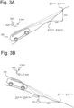
Figures 3A and 3B illustrate schematically a vehicle and how to estimate a road inclination according to an embodiment of the disclosure. -
Figure 4 illustrates schematically a vehicle and how to estimate a road banking according to an embodiment of the disclosure. -
Figures 5A and 5B illustrate schematically a vehicle and how to estimate a pothole or a road bump according to an embodiment of the disclosure. -
Figure 6 illustrates schematically an initialization of the segmented data areas representing a road according to an embodiment of the disclosure. -
Figures 7 ,8 and9 illustrate schematically the segmented data areas with current and previous detected data. -
Figure 1 illustrates a block diagram of avehicle system 102 according to the disclosure. Thevehicle system 102 may comprise aprocessing unit 104, a memory 106, asensor unit 108, and acommunication unit 110. Theprocessing unit 104 is connected to the memory 106, thesensor unit 108, and thecommunication unit 110. Thecommunication unit 110 may transmit and receive information via Bluetooth, through a wireless communication network, for example, a 4G network, and/or using any other suitable communication technology. Thesensor unit 108 may comprise sensors such as Lidar, IMU (accelerometer & gyroscope), wheel speed sensors, steering wheel sensor, etc. -
Figure 2 illustrates a flowchart schematically depicting a method a method for enabling estimation of a condition of a road according to the disclosure. The method ofFigure 2 may be performed by thevehicle system 102 ofFigure 1 . - In
step 202 of the method, the vehicle system obtains, from a sensor mounted on a vehicle, first data comprising a first plurality of data points. Each of the first plurality of data points comprises longitudinal, lateral and vertical coordinates representing respective dimensions of a part of the road at a first time. The sensor may be a three-dimensional (3D) sensor. For instance, the 3D sensor may be a lidar sensor which is part of thesensor unit 108. The lidar sensor may scan the road extending in front of the vehicle and generate the first plurality of data points. - In
step 204 of the method, the vehicle system obtains a second plurality of data points, wherein each of the second plurality of data points comprises longitudinal, lateral and vertical coordinates representing respective dimensions of the part of the road at a second time, and wherein the first time is more recent than the second time. The second plurality of data points may be stored in a memory or in a data base that the vehicle system can access. - In
step 206, the first plurality of data points is segmented into a plurality of segmented data areas or grids based on the longitudinal and lateral coordinates of the first plurality of data points. - In
step 208, a respective vertical position is estimated in each segmented data area based on the vertical coordinates of the second plurality of data points and a motion state of the vehicle at the second time. The motion state of the vehicle may be estimated based on sensor data received from one or more motion tracking sensor and/or rotation wheel speed sensors of the vehicle. The sensor data may be received from the IMU, and/or from the WSS of thesensor unit 108. The motion state of the vehicle may comprise at least one of a longitudinal velocity, a lateral velocity, a roll angle, a pitch angle and a yaw angle of the vehicle. - The method of
Figure 2 may further comprise, afterstep 208, another step of estimating the condition of the road based on the estimated respective vertical positions. - The condition of the road may comprise at least one of a curvature of the road, an inclination of the road as shown in
Figures 3A and 3B , a banking of the road as shown inFigure 4 , an anomaly of the road, and a smoothness of the road, wherein the anomaly of the road may comprise at least one of aroad bump 502 as shown inFigure 5B , an undulation, apothole 500 as shown inFigure 5A and a manhole cover. The smoothness of the road, also called pavement smoothness or roughness of the road, is a measure of minute elevation changes in the pavement surface that indicates the drivers' comfort. It may be estimated using a pavement profile (a measure of minute elevation changes in the pavement surface). Pavement profiles can be visualized as imaginary lines "drawn" along the surfaces of the pavement. Normally, pavement profiles are measured either longitudinally (down the road) or transversely (across the road). - In an alternative embodiment, the method of
Figure 2 may comprise calculating a mean of the vertical coordinates of the first plurality of data points for each segmented data area based on vertical coordinates of the first plurality of data points afterstep 206. In this alternative embodiment, step 208 may comprise estimating the condition of the road based also on the calculated means. - The method of
Figure 2 may further comprise adjusting a regenerative braking force of the vehicle based on the estimated condition, and/or adjusting a steering, a suspension and/or a speed of the vehicle based on the estimated condition, and/or adjusting a speed profile based on the estimated condition. - Furthermore, the method may also comprise obtaining second data indicative of a steering angle to estimate segmented data areas among the plurality of segmented data areas where the vehicle might travel and wherein estimating the condition of the road is further based on the estimated segmented areas.
- The
step 206 ofFigure 2 may comprise dividing a representation of the part of the road into the plurality of segmented data areas and assigning each of the first plurality of data points to a segmented data area based on the longitudinal and lateral coordinates of the first plurality of data points. -
Figure 6 shows how a representation of a part of the road in front of the vehicle can be divided into the plurality ofsegmented data areas 610. The terms grids, virtual grids and segmented data areas will be used through the description to indicate the same.Figure 6 shows the representation of a part of the road that has been divided into a plurality of 50-centimetre x 50-centimetre grids 610. This is just a non-limiting example and the representation of the road may be divided into the plurality of segmented data areas in any other way. The array of grids shown inFigure 6 is represented using a system of reference having as origin thevehicle 300 as shown inFigures 3A-3B ,4, and 5A-5B wherein the x axis, y axis and z axis respectively represent inFigures 3A, 3B ,4 and6 a longitudinal direction, a lateral direction, and a vertical direction. The longitudinal, lateral and vertical coordinates of the data points represent respective dimensions of the road in the x, y and z axis. AsFigure 6 shows a top view, the z axis is perpendicular to the array of grids.Figure 6 also shows the frontright tire position 630 and the frontleft tire position 620 of thevehicle 300. - The vertical coordinate can be used to determine whether a data point received from the lidar at a time t belongs to the road surface and not to a static or a dynamic object around or over the road surface. The data points with lowest values in the vertical coordinate below a certain threshold have the highest probability of belonging to the road and will form the first plurality of data points. The longitudinal and lateral coordinates of the first plurality of data points can be used then to assign each of the first plurality of data points to one of the
grids 610 ofFigure 6 . - A second plurality of data points is obtained, wherein the second plurality of points comprise longitudinal, lateral and vertical coordinates representing respective dimensions of the part of the road at a second time t-1, wherein the first time is more recent than the second time. The grids comprising data points that belong to the first time t and to the second tie t-1 are indicated as 702 in
Figures 7 ,8 and9 , and the grids that comprise data points that belong to the first plurality of data points but do not comprise data points that belong to the second plurality of data points are indicated as 704 inFigures 7 ,8 and9 . - As said, the motion states of the vehicle (such as longitudinal velocity, lateral velocity,
roll angle 430,pitch angle 330, yaw angle) for previous second time t-1 (in previous 100 milliseconds lidar measurement time stamp), are calculated by processing IMU and Wheel Speed Sensor (WSS) data. In this way, a mean Z t-1 of the vertical coordinates of the second plurality of points in eachgrid 610 can be used to calculate an estimated vertical position by propagating each Z t-1 to current time instant t with the transformation model as indicated below in Equation 1:
- In
Equation 1, the term 0.1 is a constant,

- In this way, Ẑt in each
grid 610 represents the estimation of the respective vertical position in the corresponding grid or segmented data area based on the vertical coordinates of the second plurality of data points and the motion state of the vehicle at the second time t-1. - The estimated respective vertical positions can be used to estimate the condition of the road.
- A measured value Zt or mean of the vertical coordinates of the first plurality of data points for each segmented data area can be calculated based on vertical coordinates of the first plurality of data points. The mean Zt of the vertical coordinates of the first plurality of data points for each
segmented data area 610 is obtained by calculating the mean of all the data points in saidsegmented data area 610 that belong to the first plurality of data points. - Then the grid's estimated respective vertical position or mean Ẑt can be combined or fused with Zt . This combination or fusion will give a grid's mean height
Zt .Equation 2 shows the simplest possible fusion or combination of Ẑt and Zt by averaging them as below:
- A steering wheel sensor may provide second data indicative of a steering angle to estimate segmented data areas among the plurality of segmented data areas where the vehicle might travel and wherein estimating the condition of the road is further based on the estimated segmented areas. In
Figures 7 and8 ,


- A predicted height of the road hroad ahead or estimated inclination of the road can be obtained from
Z t observation extending along the X axis using below Equations 3-5 and as shown in Figures 4A and 4B:


where, hroad ahead is the estimated inclination of the road,Δh observed grids 310 is a height difference component as shown inFigures 3A-3B and is based only on lidar measurements, Δhvehicle is a compensation due to current pitch angle 330 (θvehicle ) of the vehicle as shown inFigures 3A-3B and is obtained by integration of IMU gyroscope pitch rate, andΔd observed grids 320 is the length of extension of the grids from last until first as indicated inFigure 5 . - The lateral inclination broad ahead , also called forward road bank measurement or height difference in lateral direction of the vehicle, is calculated in a similar way using Equations 6-8 wherein the different parameters of Equations 6-8 are shown in
Figure 4 :


Δb vehicle 410 is a compensation due to the current roll angle (ϕvehicle ) 430 of the vehicle obtained by integration of IMU gyroscope pitch rate, andfront wheel base 420 is the distance between the centre of the front tires. - If a grid's mean
Z t and variance values are observed to be deviating beyond certain threshold to their adjacent grids, this indicates road anomalies, either abump 502 or apothole 500, along the driving direction, as inFigures 5A, 5B and9 . - Those skilled in the art will appreciate that the methods, systems and components described herein may comprise, in whole or in part, a combination of analogue and digital circuits and/or one or more appropriately programmed processors (e.g., one or more microprocessors including central processing units (CPU)) and associated memory, which may include stored operating system software, firmware and/or application software executable by the processor(s) for controlling operation thereof and/or for performing the particular algorithms represented by the various functions and/or operations described herein, including interaction between and/or cooperation with each other as well as transmitters and receivers. One or more of such processors, as well as other digital hardware, may be included in a single ASIC (Application-Specific Integrated Circuitry), or several processors and various digital hardware may be distributed among several separate components, whether individually packaged or assembled into a SoC (System-on-a-Chip).
- Furthermore, the systems, methods and components described, and/or any other arrangement, unit, system, device or module described herein may for instance be implemented in one or several arbitrary nodes comprised in the host vehicle and/or one or more separate devices. In that regard, such a node may comprise an electronic control unit (ECU) or any suitable electronic device, which may be a main or central node. It should also be noted that the these may further comprise or be arranged or configured to cooperate with any type of storage device or storage arrangement known in the art, which may for example be used for storing input or output data associated with the functions and/or operations described herein. The systems, components and methods described herein may further comprise any computer hardware and software and/or electrical hardware known in the art configured to enable communication therebetween.
- While the disclosure has been described with reference to exemplary embodiments, it will be understood by those skilled in the art that various changes may be made and equivalents may be substituted for elements thereof without departing from the scope of the disclosure. In addition, many modifications may be made to adapt a particular situation or material to the teachings of the disclosure without departing from the essential scope thereof. Therefore, it is intended that the disclosure not be limited to the particular embodiments disclosed, but that the disclosure will include all embodiments falling within the scope of the appended claims.
Claims (15)
- A method performed by a vehicle system for enabling estimation of a condition of a road, the method comprising:obtaining, from a sensor mounted on a vehicle, first data comprising a first plurality of data points, wherein each of the first plurality of data points comprises longitudinal, lateral and vertical coordinates representing respective dimensions of a part of the road at a first time;obtaining a second plurality of data points, wherein each of the second plurality of data points comprises longitudinal, lateral and vertical coordinates representing respective dimensions of the part of the road at a second time, wherein the first time is more recent than the second time;segmenting the first plurality of data points into a plurality of segmented data areas based on the longitudinal and lateral coordinates of the first plurality of data points; andestimating a respective vertical position in each segmented data area based on the vertical coordinates of the second plurality of data points and a motion state of the vehicle at the second time.
- The method according to claim 1, further comprising estimating the condition of the road based on the estimated respective vertical positions.
- The method according to claim 2, further comprising calculating a mean of the vertical coordinates of the first plurality of data points for each segmented data area based on vertical coordinates of the first plurality of data points and wherein the condition of the road is estimated based on the calculated means.
- The method according to any of the previous claims, wherein segmenting the first plurality of data points into a plurality of segmented data areas comprises dividing a representation of the part of the road into the plurality of segmented data areas and assigning each of the first plurality of data points to a segmented data area based on the longitudinal and lateral coordinates of the first plurality of data points.
- The method according to any of the previous claims, wherein the sensor comprises one or more Light Detection and Ranging, LIDAR, sensors.
- The method according to any of the previous claims, wherein the motion state of the vehicle is estimated based on sensor data received from one or more motion tracking sensor and/or rotation wheel speed sensors of the vehicle.
- The method according to claim 6, wherein the sensor data is received from an inertial measurement unit, IMU, and/or from a wheel speed sensor, WSS.
- The method according to any of the previous claims, wherein the motion state of the vehicle comprises at least one of a longitudinal velocity, a lateral velocity, a roll angle, a pitch angle and a yaw angle of the vehicle.
- The method according to claim 2 or any previous claim dependent on claim 2, wherein the condition of the road comprises at least one of a curvature of the road, an inclination of the road, a banking of the road, an anomaly of the road, and a smoothness of the road, wherein the anomaly of the road comprises at least one of a road bump, an undulation, a pothole and a manhole cover.
- The method according to claim 2 or any previous claim dependent on claim 2, further comprising adjusting a regenerative braking force of the vehicle based on the estimated condition.
- The method according to claim 2 or any previous claim dependent on claim 2, further comprising adjusting a steering, a suspension and/or a speed of the vehicle based on the estimated condition.
- The method according to claim 2 or any previous claim dependent on claim 2, further comprising adjusting a speed profile based on the estimated condition.
- The method according to claim 2 or any previous claim dependent on claim 2, further comprising obtaining second data indicative of a steering angle to estimate segmented data areas among the plurality of segmented data areas where the vehicle might travel and wherein estimating the condition of the road is further based on the estimated segmented areas.
- A vehicle system comprising a memory and a controller configured to perform the method according to any of the previous claims.
- A vehicle comprising the vehicle system according to claim 14.
Priority Applications (2)
| Application Number | Priority Date | Filing Date | Title |
|---|---|---|---|
| EP23213120.1A EP4564315A1 (en) | 2023-11-29 | 2023-11-29 | Lidar based road condition estimation for passenger vehicles |
| US18/961,534 US20250171028A1 (en) | 2023-11-29 | 2024-11-27 | Lidar based Road Condition Estimation for Passenger Vehicles |
Applications Claiming Priority (1)
| Application Number | Priority Date | Filing Date | Title |
|---|---|---|---|
| EP23213120.1A EP4564315A1 (en) | 2023-11-29 | 2023-11-29 | Lidar based road condition estimation for passenger vehicles |
Publications (1)
| Publication Number | Publication Date |
|---|---|
| EP4564315A1 true EP4564315A1 (en) | 2025-06-04 |
Family
ID=89029559
Family Applications (1)
| Application Number | Title | Priority Date | Filing Date |
|---|---|---|---|
| EP23213120.1A Pending EP4564315A1 (en) | 2023-11-29 | 2023-11-29 | Lidar based road condition estimation for passenger vehicles |
Country Status (2)
| Country | Link |
|---|---|
| US (1) | US20250171028A1 (en) |
| EP (1) | EP4564315A1 (en) |
Citations (2)
| Publication number | Priority date | Publication date | Assignee | Title |
|---|---|---|---|---|
| US20110060478A1 (en) * | 2009-09-09 | 2011-03-10 | Gm Global Technology Operations, Inc. | Vehicular terrain detection system and method |
| US20220324421A1 (en) * | 2020-12-23 | 2022-10-13 | ClearMotion, Inc. | Systems and methods for terrain-based insights for advanced driver assistance systems |
-
2023
- 2023-11-29 EP EP23213120.1A patent/EP4564315A1/en active Pending
-
2024
- 2024-11-27 US US18/961,534 patent/US20250171028A1/en active Pending
Patent Citations (2)
| Publication number | Priority date | Publication date | Assignee | Title |
|---|---|---|---|---|
| US20110060478A1 (en) * | 2009-09-09 | 2011-03-10 | Gm Global Technology Operations, Inc. | Vehicular terrain detection system and method |
| US20220324421A1 (en) * | 2020-12-23 | 2022-10-13 | ClearMotion, Inc. | Systems and methods for terrain-based insights for advanced driver assistance systems |
Also Published As
| Publication number | Publication date |
|---|---|
| US20250171028A1 (en) | 2025-05-29 |
Similar Documents
| Publication | Publication Date | Title |
|---|---|---|
| US9645250B2 (en) | Fail operational vehicle speed estimation through data fusion of 6-DOF IMU, GPS, and radar | |
| US7366602B2 (en) | Roll stability control system for an automotive vehicle using an external environmental sensing system | |
| EP2372304B1 (en) | Vehicle position recognition system | |
| JP5269024B2 (en) | Road surface state estimation device and road surface state estimation method | |
| CN108137091B (en) | Wheel slip angle estimation device and method | |
| CN113361121A (en) | Road adhesion coefficient estimation method based on time-space synchronization and information fusion | |
| US12545283B2 (en) | Architecture for variable motion control envelope | |
| US20210046928A1 (en) | Vehicle control system | |
| US12427991B2 (en) | Method for detecting surface gradient of unstructured road based on lidar | |
| US20180037082A1 (en) | Method for compensating for an inclination | |
| GB2427712A (en) | Lateral and longitudinal velocity determination for an automotive vehicle | |
| CN101793528A (en) | Use sensor fusion to estimate the system and method in path, track | |
| CN111770864A (en) | vehicle control device | |
| JP7646834B2 (en) | External Recognition System | |
| JP2007022117A (en) | Vehicle stabilization control system | |
| US12586385B2 (en) | System and method for occlusion detection in autonomous vehicle operation | |
| US20230311931A1 (en) | Systems and methods for control state estimation of vehicles | |
| CN116552562A (en) | Vehicle control device, storage medium storing computer program for vehicle control, and vehicle control method | |
| EP1022577B1 (en) | On-board GPS sensor systems | |
| CN112693454B (en) | Self-adaptive track generation method and system | |
| EP4420947A1 (en) | Vehicle control device, vehicle control method, and vehicle control system | |
| EP4306375B1 (en) | Vehicle control device, vehicle control method, and vehicle control system | |
| KR102046994B1 (en) | Estimation method of longitudinal and lateral road angle, and center of gravity position of vehicle and apparatus using the same | |
| US20250171028A1 (en) | Lidar based Road Condition Estimation for Passenger Vehicles | |
| CN119872250B (en) | Torque limiting method, electronic equipment and vehicle |
Legal Events
| Date | Code | Title | Description |
|---|---|---|---|
| PUAI | Public reference made under article 153(3) epc to a published international application that has entered the european phase |
Free format text: ORIGINAL CODE: 0009012 |
|
| STAA | Information on the status of an ep patent application or granted ep patent |
Free format text: STATUS: THE APPLICATION HAS BEEN PUBLISHED |
|
| AK | Designated contracting states |
Kind code of ref document: A1 Designated state(s): AL AT BE BG CH CY CZ DE DK EE ES FI FR GB GR HR HU IE IS IT LI LT LU LV MC ME MK MT NL NO PL PT RO RS SE SI SK SM TR |
|
| STAA | Information on the status of an ep patent application or granted ep patent |
Free format text: STATUS: REQUEST FOR EXAMINATION WAS MADE |
|
| 17P | Request for examination filed |
Effective date: 20251204 |
|
| GRAP | Despatch of communication of intention to grant a patent |
Free format text: ORIGINAL CODE: EPIDOSNIGR1 |
|
| STAA | Information on the status of an ep patent application or granted ep patent |
Free format text: STATUS: GRANT OF PATENT IS INTENDED |
|
| INTG | Intention to grant announced |
Effective date: 20260312 |