EP4564138A1 - System and method for monitoring touch events in a cockpit display - Google Patents
System and method for monitoring touch events in a cockpit display Download PDFInfo
- Publication number
- EP4564138A1 EP4564138A1 EP24215922.6A EP24215922A EP4564138A1 EP 4564138 A1 EP4564138 A1 EP 4564138A1 EP 24215922 A EP24215922 A EP 24215922A EP 4564138 A1 EP4564138 A1 EP 4564138A1
- Authority
- EP
- European Patent Office
- Prior art keywords
- touch
- display
- user
- touch event
- touch input
- Prior art date
- Legal status (The legal status is an assumption and is not a legal conclusion. Google has not performed a legal analysis and makes no representation as to the accuracy of the status listed.)
- Pending
Links
Images



Classifications
-
- B—PERFORMING OPERATIONS; TRANSPORTING
- B60—VEHICLES IN GENERAL
- B60K—ARRANGEMENT OR MOUNTING OF PROPULSION UNITS OR OF TRANSMISSIONS IN VEHICLES; ARRANGEMENT OR MOUNTING OF PLURAL DIVERSE PRIME-MOVERS IN VEHICLES; AUXILIARY DRIVES FOR VEHICLES; INSTRUMENTATION OR DASHBOARDS FOR VEHICLES; ARRANGEMENTS IN CONNECTION WITH COOLING, AIR INTAKE, GAS EXHAUST OR FUEL SUPPLY OF PROPULSION UNITS IN VEHICLES
- B60K35/00—Instruments specially adapted for vehicles; Arrangement of instruments in or on vehicles
-
- B—PERFORMING OPERATIONS; TRANSPORTING
- B60—VEHICLES IN GENERAL
- B60K—ARRANGEMENT OR MOUNTING OF PROPULSION UNITS OR OF TRANSMISSIONS IN VEHICLES; ARRANGEMENT OR MOUNTING OF PLURAL DIVERSE PRIME-MOVERS IN VEHICLES; AUXILIARY DRIVES FOR VEHICLES; INSTRUMENTATION OR DASHBOARDS FOR VEHICLES; ARRANGEMENTS IN CONNECTION WITH COOLING, AIR INTAKE, GAS EXHAUST OR FUEL SUPPLY OF PROPULSION UNITS IN VEHICLES
- B60K35/00—Instruments specially adapted for vehicles; Arrangement of instruments in or on vehicles
- B60K35/10—Input arrangements, i.e. from user to vehicle, associated with vehicle functions or specially adapted therefor
-
- B—PERFORMING OPERATIONS; TRANSPORTING
- B60—VEHICLES IN GENERAL
- B60K—ARRANGEMENT OR MOUNTING OF PROPULSION UNITS OR OF TRANSMISSIONS IN VEHICLES; ARRANGEMENT OR MOUNTING OF PLURAL DIVERSE PRIME-MOVERS IN VEHICLES; AUXILIARY DRIVES FOR VEHICLES; INSTRUMENTATION OR DASHBOARDS FOR VEHICLES; ARRANGEMENTS IN CONNECTION WITH COOLING, AIR INTAKE, GAS EXHAUST OR FUEL SUPPLY OF PROPULSION UNITS IN VEHICLES
- B60K35/00—Instruments specially adapted for vehicles; Arrangement of instruments in or on vehicles
- B60K35/20—Output arrangements, i.e. from vehicle to user, associated with vehicle functions or specially adapted therefor
- B60K35/21—Output arrangements, i.e. from vehicle to user, associated with vehicle functions or specially adapted therefor using visual output, e.g. blinking lights or matrix displays
- B60K35/22—Display screens
-
- B—PERFORMING OPERATIONS; TRANSPORTING
- B64—AIRCRAFT; AVIATION; COSMONAUTICS
- B64D—EQUIPMENT FOR FITTING IN OR TO AIRCRAFT; FLIGHT SUITS; PARACHUTES; ARRANGEMENT OR MOUNTING OF POWER PLANTS OR PROPULSION TRANSMISSIONS IN AIRCRAFT
- B64D43/00—Arrangements or adaptations of instruments
-
- G—PHYSICS
- G02—OPTICS
- G02B—OPTICAL ELEMENTS, SYSTEMS OR APPARATUS
- G02B27/00—Optical systems or apparatus not provided for by any of the groups G02B1/00 - G02B26/00, G02B30/00
- G02B27/0093—Optical systems or apparatus not provided for by any of the groups G02B1/00 - G02B26/00, G02B30/00 with means for monitoring data relating to the user, e.g. head-tracking, eye-tracking
-
- G—PHYSICS
- G02—OPTICS
- G02B—OPTICAL ELEMENTS, SYSTEMS OR APPARATUS
- G02B27/00—Optical systems or apparatus not provided for by any of the groups G02B1/00 - G02B26/00, G02B30/00
- G02B27/01—Head-up displays
- G02B27/0101—Head-up displays characterised by optical features
-
- G—PHYSICS
- G06—COMPUTING OR CALCULATING; COUNTING
- G06F—ELECTRIC DIGITAL DATA PROCESSING
- G06F3/00—Input arrangements for transferring data to be processed into a form capable of being handled by the computer; Output arrangements for transferring data from processing unit to output unit, e.g. interface arrangements
- G06F3/01—Input arrangements or combined input and output arrangements for interaction between user and computer
- G06F3/011—Arrangements for interaction with the human body, e.g. for user immersion in virtual reality
- G06F3/013—Eye tracking input arrangements
-
- G—PHYSICS
- G06—COMPUTING OR CALCULATING; COUNTING
- G06F—ELECTRIC DIGITAL DATA PROCESSING
- G06F3/00—Input arrangements for transferring data to be processed into a form capable of being handled by the computer; Output arrangements for transferring data from processing unit to output unit, e.g. interface arrangements
- G06F3/01—Input arrangements or combined input and output arrangements for interaction between user and computer
- G06F3/017—Gesture based interaction, e.g. based on a set of recognized hand gestures
-
- G—PHYSICS
- G06—COMPUTING OR CALCULATING; COUNTING
- G06F—ELECTRIC DIGITAL DATA PROCESSING
- G06F3/00—Input arrangements for transferring data to be processed into a form capable of being handled by the computer; Output arrangements for transferring data from processing unit to output unit, e.g. interface arrangements
- G06F3/01—Input arrangements or combined input and output arrangements for interaction between user and computer
- G06F3/03—Arrangements for converting the position or the displacement of a member into a coded form
- G06F3/041—Digitisers, e.g. for touch screens or touch pads, characterised by the transducing means
- G06F3/0412—Digitisers structurally integrated in a display
-
- G—PHYSICS
- G06—COMPUTING OR CALCULATING; COUNTING
- G06F—ELECTRIC DIGITAL DATA PROCESSING
- G06F3/00—Input arrangements for transferring data to be processed into a form capable of being handled by the computer; Output arrangements for transferring data from processing unit to output unit, e.g. interface arrangements
- G06F3/01—Input arrangements or combined input and output arrangements for interaction between user and computer
- G06F3/048—Interaction techniques based on graphical user interfaces [GUI]
-
- G—PHYSICS
- G06—COMPUTING OR CALCULATING; COUNTING
- G06F—ELECTRIC DIGITAL DATA PROCESSING
- G06F3/00—Input arrangements for transferring data to be processed into a form capable of being handled by the computer; Output arrangements for transferring data from processing unit to output unit, e.g. interface arrangements
- G06F3/01—Input arrangements or combined input and output arrangements for interaction between user and computer
- G06F3/048—Interaction techniques based on graphical user interfaces [GUI]
- G06F3/0484—Interaction techniques based on graphical user interfaces [GUI] for the control of specific functions or operations, e.g. selecting or manipulating an object, an image or a displayed text element, setting a parameter value or selecting a range
- G06F3/04842—Selection of displayed objects or displayed text elements
-
- G—PHYSICS
- G06—COMPUTING OR CALCULATING; COUNTING
- G06F—ELECTRIC DIGITAL DATA PROCESSING
- G06F3/00—Input arrangements for transferring data to be processed into a form capable of being handled by the computer; Output arrangements for transferring data from processing unit to output unit, e.g. interface arrangements
- G06F3/01—Input arrangements or combined input and output arrangements for interaction between user and computer
- G06F3/048—Interaction techniques based on graphical user interfaces [GUI]
- G06F3/0487—Interaction techniques based on graphical user interfaces [GUI] using specific features provided by the input device, e.g. functions controlled by the rotation of a mouse with dual sensing arrangements, or of the nature of the input device, e.g. tap gestures based on pressure sensed by a digitiser
- G06F3/0488—Interaction techniques based on graphical user interfaces [GUI] using specific features provided by the input device, e.g. functions controlled by the rotation of a mouse with dual sensing arrangements, or of the nature of the input device, e.g. tap gestures based on pressure sensed by a digitiser using a touch-screen or digitiser, e.g. input of commands through traced gestures
-
- B—PERFORMING OPERATIONS; TRANSPORTING
- B60—VEHICLES IN GENERAL
- B60K—ARRANGEMENT OR MOUNTING OF PROPULSION UNITS OR OF TRANSMISSIONS IN VEHICLES; ARRANGEMENT OR MOUNTING OF PLURAL DIVERSE PRIME-MOVERS IN VEHICLES; AUXILIARY DRIVES FOR VEHICLES; INSTRUMENTATION OR DASHBOARDS FOR VEHICLES; ARRANGEMENTS IN CONNECTION WITH COOLING, AIR INTAKE, GAS EXHAUST OR FUEL SUPPLY OF PROPULSION UNITS IN VEHICLES
- B60K2360/00—Indexing scheme associated with groups B60K35/00 or B60K37/00 relating to details of instruments or dashboards
- B60K2360/143—Touch sensitive instrument input devices
-
- B—PERFORMING OPERATIONS; TRANSPORTING
- B60—VEHICLES IN GENERAL
- B60K—ARRANGEMENT OR MOUNTING OF PROPULSION UNITS OR OF TRANSMISSIONS IN VEHICLES; ARRANGEMENT OR MOUNTING OF PLURAL DIVERSE PRIME-MOVERS IN VEHICLES; AUXILIARY DRIVES FOR VEHICLES; INSTRUMENTATION OR DASHBOARDS FOR VEHICLES; ARRANGEMENTS IN CONNECTION WITH COOLING, AIR INTAKE, GAS EXHAUST OR FUEL SUPPLY OF PROPULSION UNITS IN VEHICLES
- B60K2360/00—Indexing scheme associated with groups B60K35/00 or B60K37/00 relating to details of instruments or dashboards
- B60K2360/143—Touch sensitive instrument input devices
- B60K2360/1438—Touch screens
-
- B—PERFORMING OPERATIONS; TRANSPORTING
- B60—VEHICLES IN GENERAL
- B60K—ARRANGEMENT OR MOUNTING OF PROPULSION UNITS OR OF TRANSMISSIONS IN VEHICLES; ARRANGEMENT OR MOUNTING OF PLURAL DIVERSE PRIME-MOVERS IN VEHICLES; AUXILIARY DRIVES FOR VEHICLES; INSTRUMENTATION OR DASHBOARDS FOR VEHICLES; ARRANGEMENTS IN CONNECTION WITH COOLING, AIR INTAKE, GAS EXHAUST OR FUEL SUPPLY OF PROPULSION UNITS IN VEHICLES
- B60K2360/00—Indexing scheme associated with groups B60K35/00 or B60K37/00 relating to details of instruments or dashboards
- B60K2360/18—Information management
- B60K2360/199—Information management for avoiding maloperation
-
- G—PHYSICS
- G02—OPTICS
- G02B—OPTICAL ELEMENTS, SYSTEMS OR APPARATUS
- G02B27/00—Optical systems or apparatus not provided for by any of the groups G02B1/00 - G02B26/00, G02B30/00
- G02B27/01—Head-up displays
- G02B27/0101—Head-up displays characterised by optical features
- G02B2027/0138—Head-up displays characterised by optical features comprising image capture systems, e.g. camera
-
- G—PHYSICS
- G02—OPTICS
- G02B—OPTICAL ELEMENTS, SYSTEMS OR APPARATUS
- G02B27/00—Optical systems or apparatus not provided for by any of the groups G02B1/00 - G02B26/00, G02B30/00
- G02B27/01—Head-up displays
- G02B27/0101—Head-up displays characterised by optical features
- G02B2027/014—Head-up displays characterised by optical features comprising information/image processing systems
Definitions
- the subject matter disclosed herein relates to the field of flight displays and, in particular, to a system and method for monitoring touch events in flight displays.
- Flight displays often utilize touchscreens across all segments of aviation.
- the sensing algorithms of the touchscreens may incorrectly register a touch point for multiple reasons.
- the impact of inadvertent touch may result in an extended task time and/or may result in an unintended input that may impact more critical aircraft system setting(s), configuration(s), and/or control(s).
- the system includes one or more user interface devices including a display and a user input device, where the user input device includes a touchscreen interface configured to receive a user touch input.
- the display includes one or more display touch sensors configured to detect spatial-temporal touch event data associated with the user touch input.
- the system includes one or more user monitoring devices including one or more eye tracking sensors configured to detect an eye gaze of a user viewing the display and one or more body tracking sensors configured to detect body movement of the user viewing the display.
- the system includes one or more controllers communicatively coupled to the one or more user monitoring devices and the one or more user interface devices.
- the one or more controllers include one or more processors configured to execute a set of program instructions stored in memory.
- the memory includes a touch event algorithm configured to detect inadvertent touch events.
- the set of program instructions configured to cause the one or more processors to receive eye gaze data of the user viewing the display from the one or more eye tracking sensors.
- the set of program instructions configured to cause the one or more processors to receive body movement data of the user viewing the display from the one or more body tracking sensors.
- the set of program instructions configured to cause the one or more processors to receive the spatial-temporal touch event data of the user viewing the display from the one or more display touch sensors.
- the set of program instructions configured to cause the one or more processors to compare the spatial-temporal touch event data with touch event signature data in a touch event signature database. In embodiments, the set of program instructions configured to cause the one or more processors to determine whether the received user touch input is an inadvertent touch event based on the compared spatial-temporal touch event data and at least one of the eye gaze data or the body movement data. In embodiments, upon determining the received user touch input is an inadvertent touch, the set of program instructions are configured to cause the one or more processors to perform a first set of one or more avionic system actions.
- the set of program instructions are configured to cause the one or more processors to perform a second set of one or more avionic system actions, wherein the second set of one or more avionic system actions are different than the first set of one or more avionic system actions.
- the first set of one or more avionic system actions may include ignoring the user touch input by not providing the received user touch input to an avionics system.
- the first set of one or more avionic system actions may include generating one or more control signals configured to cause the display to display an on-screen pop-up, wherein the on-screen pop-up allows the user to confirm whether the user touch input is an inadvertent touch.
- the second set of one or more avionic system actions may include providing the received user touch input to one or more avionic systems.
- the set of program instructions may be further configured to cause the one or more processors to adjust one or more selectable buttons on a graphical user interface of the display.
- the received user touch input is an inadvertent touch
- the received user touch input is an inadvertent touch
- the received user touch input is an inadvertent touch
- the received user touch input is an intentional touch
- the one or more eye tracking sensors may include one or more eye tracking cameras.
- the one or more body tracking sensors may include one or more body tracking cameras.
- the one or more eye tracking sensors and the one or more body tracking sensors may be integrated into a common interface.
- the one or more eye tracking sensors and the one or more body tracking sensors may be separated.
- the method includes receiving one or more inputs from a user via a touchscreen interface of one or more user interface devices, where the one or more user interface devices include a display.
- the method includes detecting an eye gaze of the user viewing the display using one or more eye tracking sensors.
- the method includes detecting body movement of the user viewing the display using one or more body tracking sensors.
- the method includes receiving spatial-temporal touch event data of the user viewing the display from one or more display touch sensors.
- the method includes comparing the spatial-temporal touch event data with touch event signature data in a touch event signature database.
- the method includes determining whether the received user touch input is an inadvertent touch event based on the compared spatial-temporal touch event data and at least one of detected eye gaze data from the one or more eye tracking sensors or detected body movement data from the one or more body tracking sensors.
- the method upon determining the received user touch input is an inadvertent touch, the method includes performing a first set of one or more avionic system actions.
- the method upon determining the received user touch input is an intentional touch, includes performing a second set of one or more avionic system actions, wherein the second set of one or more avionic system actions are different than the first set of one or more avionic system actions.
- the first set of one or more avionic system actions may include ignoring the user touch input by not providing the received user touch input to an avionics system.
- the first set of one or more avionic system actions may include generating one or more control signals configured to cause the display to display an on-screen pop-up, wherein the on-screen pop-up allows the user to confirm whether the user touch input is an inadvertent touch.
- the first set of one or more avionic system actions may include providing the received user touch input to one or more avionic systems.
- the method may further include adjusting one or more selectable buttons on a graphical user interface of the display.
- a letter following a reference numeral is intended to reference an embodiment of the feature or element that may be similar, but not necessarily identical, to a previously described element or feature bearing the same reference numeral (e.g., 1, 1a, 1b).
- reference numeral e.g. 1, 1a, 1b
- Such shorthand notations are used for purposes of convenience only and should not be construed to limit the disclosure in any way unless expressly stated to the contrary.
- any reference to “one embodiment” or “some embodiments” means that a particular element, feature, structure, or characteristic described in connection with the embodiment is included in at least one embodiment disclosed herein.
- the appearances of the phrase “in some embodiments” in various places in the specification are not necessarily all referring to the same embodiment, and embodiments may include one or more of the features expressly described or inherently present herein, or any combination of or sub-combination of two or more such features, along with any other features which may not necessarily be expressly described or inherently present in the instant disclosure.
- Flight displays often utilize touchscreens across all segments of aviation.
- the sensing algorithms of the touchscreens may incorrectly register a touch point for multiple reasons.
- the occurrence of such inadvertent touch is important in a cockpit environment.
- the impact of inadvertent touch may result in an extended task time and/or may result in an unintended input that may impact more critical aircraft system setting(s), configuration(s), and/or control(s) (e.g., incorrect selection of a waypoint or value, unintended toggle of a soft switch, or the like).
- control(s) e.g., incorrect selection of a waypoint or value, unintended toggle of a soft switch, or the like.
- the system and method should track a viewer's eye gaze.
- the system and method may track body movements (e.g., hand movements, or the like).
- the system and method provide a valid touch event confidence state level (e.g., high probability, medium probability, or low probability). For example, based on the confidence state level of the touch event, the system and method may perform one or more predetermined actions. For instance, where a low confidence state level is determined, the detected event(s) may be ignored. In another instance, where a high confidence state level is determined, the detected event(s) may be executed.
- the system and method should help to declutter keyable touch input graphics. For example, the keyable input graphics may be subdued, scaled down, or hidden from the display screen when no intent for touch is detected.
- interaction with a touch display requires direct and intentional viewing of the target immediately prior to touch selection, as well as a coordinated movement of the viewer's arm/hand.
- a given cockpit layout is highly engineered and provides a controlled environment with flight displays being placed at exacting locations with fixed sizes and orientations to each crew position.
- the tracking of a viewer's eye gaze (and/or body movements) is enabled to allow the system and method to utilize the tracked eye gaze (and/or body movements) to validate a touch event before communicating it to the aircraft system to thus, decrease the occurrence of inadvertent touch events.
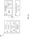
- FIG. 1A illustrates a simplified block diagram of an aircraft 100 including a system 101 for monitoring touch events in a cockpit display, in accordance with one or more embodiments of the present disclosure.
- FIG. 1B illustrates a simplified schematic of an aircraft cockpit 103 including the system 101 for monitoring touch events in a cockpit display, in accordance with one or more embodiments of the disclosure.
- the aircraft 100 may include an aircraft controller 102.
- the aircraft controller 102 may include one or more processors 104, memory 106 configured to store one or more program instructions, and/or one or more communication interfaces 110.
- the aircraft 100 may include an avionics environment such as, but not limited to, a cockpit 103.
- the aircraft controller 102 may be coupled (e.g., physically, electrically, and/or communicatively) to one or more display devices 112. Referring now to FIG.
- the avionics environment may include any number of display devices 112 (e.g., one, two, three, or more displays) such as, but not limited to, one or more head-down displays (HDDs) 112, one or more head-up displays (HUDs) 112, one or more multi-function displays (MFDs), one or more adaptive flight displays (AFDs) 112, one or more primary flight displays (PFDs) 112, one or more electronic flight bags (EFBs) 112, or the like.
- display devices 112 e.g., one, two, three, or more displays
- HDDs head-down displays
- HUDs head-up displays
- MFDs multi-function displays
- AFDs adaptive flight displays
- PFDs primary flight displays
- EFBs electronic flight bags
- the aircraft controller 102 may be coupled (e.g., physically, electrically, and/or communicatively) to one or more user input devices 114.
- the one or more display devices 112 may be coupled to the one or more user input devices 114.
- the one or more display devices 112 may be coupled to the one or more user input devices by a transmission medium that may include wireline and/or wireless portions.
- the one or more display devices 112 may include and/or be configured to interact with one or more user input devices 114.
- the one or more user input devices 114 may include a touchscreen interface.
- the display device 112 may be integrated with a touchscreen interface 114, such as, but not limited to, a capacitive touchscreen, a resistive touchscreen, a surface acoustic based touchscreen, an infrared based touchscreen, or the like.
- a touchscreen interface 114 such as, but not limited to, a capacitive touchscreen, a resistive touchscreen, a surface acoustic based touchscreen, an infrared based touchscreen, or the like.
- any touchscreen interface capable of integration with the display portion of a display device is suitable for implementation in the present invention.
- the one or more input devices 114 may further include, but are not limited to, a keyboard, a keypad, a lever, a knob, a scroll wheel, a track ball, a switch, a dial, a sliding bar, a scroll bar, a slide, a handle, a touch pad, a paddle, a steering wheel, a joystick, a bezel input device, or the like.
- the display devices 112 may include, but are not limited to, a liquid crystal display (LCD), a light-emitting diode (LED) based display, an organic light-emitting diode (OLED) based display, an electroluminescent display (ELD), an electronic paper (E-ink) display, a plasma display panel (PDP), a display light processing (DLP) display, a micro-LED display, a quantum dot electroluminescent (QD-EL) display, or the like.
- LCD liquid crystal display
- LED light-emitting diode
- OLED organic light-emitting diode
- ELD electroluminescent display
- E-ink electronic paper
- PDP plasma display panel
- DLP display light processing
- micro-LED micro-LED display
- QD-EL quantum dot electroluminescent
- the one or more display devices 112 and the one or more user input devices 114 may be standalone components within the aircraft 100. It is noted herein, however, that the one or more display devices 112 and the one or more user input devices may be integrated within one or more common user interfaces 116. Where the one or more display devices 112 and the one or more user input devices 114 are housed within the one or more common user interfaces 116, the aircraft controller 102 and/or the one or more common user interfaces may be standalone components. It is noted herein, however, that the aircraft controller 102 and/or the one or more common user interfaces 116 may be integrated within one or more common housings or chassis.
- the display 112 may be configured to display an avionics graphical user interface (GUI) including one or more keyable icons.
- GUI avionics graphical user interface
- the one or more keyable icons may be selected via the touchscreen interface of the user input device 114.
- inadvertent selection of one of the one or more keyable icons may result in an unintended input that may impact more critical aircraft system setting(s), configuration(s), and/or control(s).
- the system 101 may include one or more user monitoring devices 118.
- the one or more user monitoring devices 118 may be communicatively coupled to the aircraft controller 102.
- the one or more user monitoring devices 118 may be configured to monitor a user for one or more touch event parameters.
- the one or more user monitoring devices 118 may be configured to monitor a crew member's (e.g., pilot, co-pilot, or the like) eye gaze (or fixation).
- the one or more user monitoring devices 118 may be configured to monitor a crew member's (e.g., pilot, co-pilot, or the like) body movement (e.g., arms, hands, shoulders, or the like).
- the one or more user monitoring devices 118 may be configured to monitor a crew member's (e.g., pilot, co-pilot, or the like) body posture.
- the user monitoring device 118 may include one or more eye tracking sensors 120 configured to detect a current gaze of a user viewing the display 112.
- the one or more eye tracking sensors 120 may include one or more eye tracking cameras 120 coupled to one or more portions of a cockpit (such as the cockpit 103 shown in FIG. 1B ), where the one or more eye tracking cameras 120 are configured to generate at least one of one or more images 121 or one or more videos 121 including the user's eye gaze.
- the one or more eye tracking cameras 120 may include at least one camera 120 mounted straight facing (e.g., in front of) the pilot.
- the one or more eye tracking cameras 120 may include at least one camera 120 mounted to the left and/or right of the pilot.
- the one or more eye tracking cameras 120 may include at least one camera 120 mounted above the pilot (e.g., facing downward). It is noted that the camera 120 may be mounted in any suitable location within the cockpit to accurately capture one or more images and/or videos 121 of the eye gaze of the pilot.
- the one or more eye tracking sensors 120 may include one or more structured light emitters along with one or more image sensors with digital processing algorithms configured to track at least one of head, hand, and/or eye positions.
- the user monitoring device 118 may include one or more body movement tracking sensors 122 configured to detect body movement of a user using the display 112.
- the one or more body movement tracking sensors 122 may include one or more body movement tracking cameras 122 coupled to one or more portions of a cockpit (such as the cockpit 103 shown in FIG. 1B ), where the one or more body movement tracking cameras 122 are configured to generate at least one of one or more images 121 or one or more videos 121 including the user's body movement (e.g., movement of the arms, head, shoulders, or the like).
- the one or more body movement tracking cameras 122 may include at least one camera 122 mounted straight facing (e.g., in front of) the pilot.
- the one or more body movement tracking cameras 122 may include at least one camera 122 mounted to the left and/or right of the pilot. In another instance, the one or more body movement tracking cameras 122 may include at least one camera 122 mounted above the pilot (e.g., facing downward). It is noted that the camera 122 may be mounted in any suitable location within the cockpit to accurately capture one or more images and/or videos 121 of a user's body movement (e.g., movement of the arms, head, shoulders, or the like).
- the one or more body movement tracking sensors 122 may include, but are not limited to, one or more thermal sensors (e.g., thermal imaging cameras), one or more visible cameras (e.g., LIDAR cameras), one or more radar devices, one or more time of flight sensors, one or more body worn sensors (e.g., on arms, wrist, hand(s), head, or the like).
- thermal sensors e.g., thermal imaging cameras
- visible cameras e.g., LIDAR cameras
- radar devices e.g., one or more radar devices
- time of flight sensors e.g., on arms, wrist, hand(s), head, or the like.
- FIG. 1A depicts the eye tracking sensors 120 and the body movement tracking sensor 122 as separate components, it is contemplated herein that eye tracking sensor 120 and the body movement tracking sensor 122 may be a single sensor configured to detect both eye gaze and body movement. Rather, FIGS. 1A-1B are provided merely for illustrative purposes and shall not be construed as limiting the scope of the present disclosure.
- the system 101 may include one or more display touch sensors 123.
- the touchscreen interface of the user input device 114 may include one or more display touch sensors 123.
- the one or more display touch sensors 123 may be configured to detect user interaction with the touchscreen interface of the user input device 114.
- the one or more display touch sensors 123 may be configured to detect touch events between the user and the touchscreen interface of the user input device 114.
- the system 101 may include a touch event signature database 125.
- the aircraft controller 102 may include the touch event signature database 125 stored in memory 106.
- the touch event signature database 125 may be stored in a remote database and be communicatively coupled to the aircraft controller 102.
- the touch event signature database 125 may include one or more valid touch event signatures that indicate an intentional touch event has occurred. In this regard, a comparison between the detected touch event from the display touch sensor 123 and the touch event signatures of the database 125 may be used to determine whether the touch was intentional (e.g., valid) or inadvertent (e.g., invalid).
- the aircraft controller 102 may include a touch event algorithm 124 stored in memory 106.
- the one or more processors 104 may be configured to validate a touch event between the pilot and the touchscreen interface 114 using the touch event algorithm 124.
- the touch event algorithm 124 of the one or more processors 104 may be configured to validate one or more touch events based on at least one of the user's eye gaze from the eye gaze sensors 120, the user's body movement from the body movement sensors 122, or the display touch data from the display touch sensors 123.
- the one or more processors 104 may be configured to perform one or more actions based on touch event validation data from the touch event algorithm 124.
- the one or more processors 104 may ignore the detected touch event when the touch event algorithm 124 identifies an inadvertent touch, as discussed further herein. In another instance, the one or more processors 104 may request an on-screen confirmation of detected touch event when the touch event algorithm 124 identifies a possible inadvertent touch, as discussed further herein. In another instance, the one or more processors 104 may execute the detected touch event when the touch event algorithm 124 identifies a valid touch, as discussed further herein. By way of another example, the one or more processors 104 may be configured to adjust the display 112 based on touch event validation data from the touch event algorithm 124.
- the one or more processors 104 may decrease a size of the GUI (or one or more selectable icons of the GUI) when the touch event algorithm 124 identifies an inadvertent touch (or possible inadvertent touch), as discussed further herein. In another instance, the one or more processors 104 may decrease a transparency of the GUI (or one or more selectable icons of the GUI) when the touch event algorithm 124 identifies an inadvertent touch (or possible inadvertent touch), as discussed further herein.
- the one or more processors 104 may hide the GUI (or one or more selectable icons of the GUI) when the touch event algorithm 124 identifies a inadvertent/invalid touch (or possible inadvertent touch), as discussed further herein.
- the one or more processors 104 may increase a size of the GUI (or one or more selectable icons of the GUI) when the touch event algorithm 124 identifies a valid/intentional touch, as discussed further herein.
- the one or more processors 104 may sharpen the appearance of the GUI (or one or more selectable icons of the GUI) when the touch event algorithm 124 identifies a valid/intentional touch, as discussed further herein.
- FIGS. 2A-2C one or more confidence states of the touch event validation of the touch event algorithm 124 of the system 101 are shown.
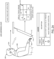
- FIG. 2A illustrates a low confidence state of the system for monitoring touch events in a cockpit display, in accordance with one or more embodiments of the disclosure.
- FIG. 2B illustrates a medium confidence state of the system for monitoring touch events in a cockpit display, in accordance with one or more embodiments of the disclosure.
- FIG. 2C illustrates a high confidence state of the system for monitoring touch events in a cockpit display, in accordance with one or more embodiments of the disclosure.
- a given cockpit layout is highly engineered and provides a controlled environment with flight displays being placed at exacting locations with fixed sizes and orientations to each crew position.
- the system 101 is able to monitor the one or more touch event parameters to validate a touch event before communicating it to the aircraft system and decrease the occurrence of inadvertent touch events.
- the system 101 may be configured to identify two or more inadvertent touch events based on at least one of the user's eye gaze from the eye gaze sensors 120, the user's body movement from the body movement sensors 122, or the display touch data from the display touch sensors 123. For example, in a non-limiting example, two or more inadvertent touch events may be identified where the eye gaze sensors 120 detect that the user's eye gaze is not directed towards the display 112. By way of another non-limiting example, two or more inadvertent touch events may be identified where the body movement sensors 122 detect that that user's body position does not match the criteria for a touch event.
- a user's body position may not match the criteria for a touch event when the user's arm is not extended towards the display 112. In another instance, a user's body position may not match the criteria for a touch event when the user's body is turned away from the display 112 (e.g., a user's head may be tilted down in the direction of displays).
- two or more inadvertent touch events may be identified where the display sensors 123 identify no matches between the detected touch event(s) and touch event signatures stored in the touch event signature database 125.
- the system 101 may be configured to assign a confidence state level, using the touch event algorithm 124, based on the touch event data. It is contemplated herein that reference to "low”, “medium”, and “high” confidence states is merely for illustrative purposes and shall not be construed as limiting the scope of the present disclosure. For example, the confidence states may be referred to as a first confidence state, a second confidence state, a third confidence state, or the like.
- a low confidence state is shown.
- the term "low confidence state” may be defined as a state where no valid touch event is detected (e.g., only inadvertent touch events are detected), in accordance with one or more embodiments of the present disclosure.
- a user's 200 eye gaze 204 may not be directed towards the display 112
- the user's 200 arms/hands 206 may not be extended towards the display 112
- the user's 200 body 208 may not be directed towards the display.
- the display touch sensors 123 may detect sporadic touch events 210 (e.g., touch events spaced sporadically throughout the display), where the sporadic touch events 210 do not match any of the touch event signatures stored in the database 125.
- one or more processors 104 may be configured to perform one or more actions based on touch event validation data from the touch event algorithm 124. In one non-limiting example, the one or more processors 104 may ignore the detected touch event when the touch event algorithm 124 identifies an inadvertent touch.
- the one or more processors 104 may be further configured to adjust the display 112 based on touch event validation data from the touch event algorithm 124.
- the one or more processors 104 may decrease a size of the GUI (or one or more selectable icons of the GUI) when the touch event algorithm 124 identifies an inadvertent touch.
- the one or more processors 104 may decrease a transparency of the GUI (or one or more selectable icons of the GUI) when the touch event algorithm 124 identifies an inadvertent touch.
- the one or more processors 104 may hide the GUI (or one or more selectable icons of the GUI) when the touch event algorithm 124 identifies a inadvertent/invalid touch.
- medium confidence state may be defined as a state where possible valid touch event(s) is/are detected, in accordance with one or more embodiments of the present disclosure.
- a user's 212 eye gaze 214 may be directed towards the display 112, the user's 212 arms/hands 216 may not be extended towards the display 112, and the user's 212 body 218 may be directed towards the display.
- the display touch sensors 123 may detect sporadic touch events 220 (e.g., touch events spaced sporadically throughout the display), where the sporadic touch events 220 do not match any of the touch event signatures stored in the database 125 and a grouping 222 of touch events.
- some of the touch event parameters indicate that a valid/intentional touch event occurred (e.g., eye gaze toward display, body towards display, and grouping of touch events 222), while some of the touch event parameters indicate that an inadvertent/invalid touch event occurred (e.g., sporadic touch events 220 and arms/hands not extended towards display 112).
- a valid/intentional touch event e.g., eye gaze toward display, body towards display, and grouping of touch events 222
- an inadvertent/invalid touch event e.g., sporadic touch events 220 and arms/hands not extended towards display 112
- one or more processors 104 may be configured to perform one or more actions based on touch event validation data from the touch event algorithm 124. In one non-limiting example, the one or more processors 104 may ignore the detected touch event when the touch event algorithm 124 identifies a possible inadvertent touch. In another non-limiting example, the one or more processors 104 may request an on-screen confirmation of detected touch event when the touch event algorithm 124 identifies a possible inadvertent touch.
- the one or more processors 104 may be further configured to adjust the display 112 based on touch event validation data from the touch event algorithm 124.
- the one or more processors 104 may decrease a size of the GUI (or one or more selectable icons of the GUI) when the touch event algorithm 124 identifies a possible inadvertent touch.
- the one or more processors 104 may decrease a transparency of the GUI (or one or more selectable icons of the GUI) when the touch event algorithm 124 identifies a possible inadvertent touch.
- the one or more processors 104 may hide the GUI (or one or more selectable icons of the GUI) when the touch event algorithm 124 identifies a possible inadvertent touch.
- high confidence state may be defined as a state where valid touch event(s) is/are detected, in accordance with one or more embodiments of the present disclosure.
- a user's 224 eye gaze 226 may be directed towards the display 112
- the user's 224 arms/hands 228 may be extended towards the display 112
- the user's 224 body 230 may be directed towards the display.
- the display touch sensors 123 may detect a blob 232 that matches a touch event signature stored in the database 125.
- the one or more processors 104 may execute the detected touch event when the touch event algorithm 124 identifies a valid touch.
- the one or more processors 104 may be further configured to adjust the display 112 based on touch event validation data from the touch event algorithm 124. In one instance, the one or more processors 104 may increase a size of the GUI (or one or more selectable icons of the GUI) when the touch event algorithm 124 identifies a valid/intentional touch. In another instance, the one or more processors 104 may sharpen the appearance of the GUI (or one or more selectable icons of the GUI) when the touch event algorithm 124 identifies a valid/intentional touch.
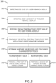
- FIG. 3 illustrates a flow diagram depicting a method or process 300 of monitoring touch events, in accordance with one or more embodiments of the present disclosure.
- the eye gaze of a user viewing a display may be detected.
- the body movement of a user viewing a display may be detected.
- spatial-temporal touch event data of a user viewing a display may be detected.
- the spatial-temporal touch event data may be compared to data within a touch event signature database.
- inadvertent touches may be determined.
- a first set of one or more avionics system actions may be performed.
- a second set of one or more avionics system actions may be performed.
- embodiments of the methods disclosed herein may include one or more of the steps described herein. Further, such steps may be carried out in any desired order and two or more of the steps may be carried out simultaneously with one another. Two or more of the steps disclosed herein may be combined in a single step, and in some embodiments, one or more of the steps may be carried out as two or more sub-steps. Further, other steps or sub-steps may be carried in addition to, or as substitutes to, one or more of the steps disclosed herein.
- one or more embodiments of the present disclosure are directed to a touch event monitoring system for an aircraft cockpit, it is noted herein that the system and method may be directed for monitoring a touch event for any type of vehicle operator environment.
- the one or more components of system 101 may be communicatively coupled to the various other components of system 101 in any manner known in the art.
- the one or more processors 104 may be communicatively coupled to each other and other components via a wireline (e.g., copper wire, fiber optic cable, and the like) or wireless connection (e.g., RF coupling, IR coupling, WiMax, Bluetooth, 3G, 4G, 4G LTE, 5G, and the like).
- the controller 102 may be communicatively coupled to one or more components of the system 100 via any wireline or wireless connection known in the art.
- the one or more processors 104 may include any one or more processing elements known in the art. In this sense, the one or more processors 104 may include any microprocessor device configured to execute algorithms and/or program instructions. In general, the term "processor" may be broadly defined to encompass any device having one or more processing elements, which execute a set of program instructions from a non-transitory memory medium (e.g., the memory 106), where the one or more sets of program instructions are configured to cause the one or more processors 104 to carry out any of one or more process steps.
- a non-transitory memory medium e.g., the memory 106
- the memory 106 may include any storage medium known in the art suitable for storing the one or more sets of program instructions executable by the associated one or more processors 104.
- the memory 106 may include a non-transitory memory medium.
- the memory 106 may include, but is not limited to, a read-only memory (ROM), a random access memory (RAM), a magnetic or optical memory device (e.g., disk), a magnetic tape, a solid state drive, and the like.
- the memory 106 may be configured to provide display information to the user device.
- the memory 106 may be configured to store user input information from one or more user input devices.
- the memory 106 may be housed in a common controller housing with the one or more processors 104.
- the memory 106 may, alternatively or in addition, be located remotely with respect to the spatial location of the processors 104 and/or the one or more controllers 102.
- the one or more processors 104, the one or more controllers 102 may access a remote database, accessible through a network (e.g., internet, intranet, and the like) via one or more communication interfaces.
- a network e.g., internet, intranet, and the like
- the one or more communication interfaces may be operatively configured to communicate with one or more components of the one or more controllers 102 and/or the one or more components of the system.
- the one or more communication interfaces may also be coupled (e.g., physically, electrically, and/or communicatively) with the one or more processors 104 to facilitate data transfer between components of the one or more components of the one or more controllers 102 and/or the one or more components of the system 101 and the one or more processors 104.
- the one or more communication interfaces may be configured to retrieve data from the one or more processors 104, or other devices, transmit data for storage in the memory 106, retrieve data from storage in the memory 106, or the like.
Landscapes
- Engineering & Computer Science (AREA)
- Theoretical Computer Science (AREA)
- General Engineering & Computer Science (AREA)
- Physics & Mathematics (AREA)
- General Physics & Mathematics (AREA)
- Human Computer Interaction (AREA)
- Chemical & Material Sciences (AREA)
- Combustion & Propulsion (AREA)
- Transportation (AREA)
- Mechanical Engineering (AREA)
- Optics & Photonics (AREA)
- Aviation & Aerospace Engineering (AREA)
- User Interface Of Digital Computer (AREA)
Abstract
A system for monitoring touch events in a cockpit display includes one or more user monitoring devices (116) including eye tracking sensors (120) and body tracking sensors (122). The system includes a controller (102) including a touch event algorithm configured to determine inadvertent touch events. The controller may receive eye gaze and body movement data of the user viewing the display (112). The controller may receive the spatial-temporal touch event data and compare the spatial-temporal touch event data with touch event signature data in a touch event signature database. The controller may determine whether the received user touch input is an inadvertent touch event. Upon determining the user touch input is an inadvertent touch, the controller may perform a first set of avionic system actions and upon determining the user touch input is an intentional touch, the controller may perform a second set of avionic system actions.
Description
- The subject matter disclosed herein relates to the field of flight displays and, in particular, to a system and method for monitoring touch events in flight displays.
- Flight displays often utilize touchscreens across all segments of aviation. The sensing algorithms of the touchscreens may incorrectly register a touch point for multiple reasons. The impact of inadvertent touch may result in an extended task time and/or may result in an unintended input that may impact more critical aircraft system setting(s), configuration(s), and/or control(s). As such, there is a need for a system and method to reduce the likelihood of inadvertent touch events and decrease the possibility of inadvertent touch events from occurring.
- A system for monitoring touch events in a cockpit display is disclosed, in accordance with one or more embodiments of the present disclosure. In embodiments, the system includes one or more user interface devices including a display and a user input device, where the user input device includes a touchscreen interface configured to receive a user touch input. In embodiments, the display includes one or more display touch sensors configured to detect spatial-temporal touch event data associated with the user touch input. In embodiments, the system includes one or more user monitoring devices including one or more eye tracking sensors configured to detect an eye gaze of a user viewing the display and one or more body tracking sensors configured to detect body movement of the user viewing the display. In embodiments, the system includes one or more controllers communicatively coupled to the one or more user monitoring devices and the one or more user interface devices. In embodiments, the one or more controllers include one or more processors configured to execute a set of program instructions stored in memory. In embodiments, the memory includes a touch event algorithm configured to detect inadvertent touch events. In embodiments, the set of program instructions configured to cause the one or more processors to receive eye gaze data of the user viewing the display from the one or more eye tracking sensors. In embodiments, the set of program instructions configured to cause the one or more processors to receive body movement data of the user viewing the display from the one or more body tracking sensors. In embodiments, the set of program instructions configured to cause the one or more processors to receive the spatial-temporal touch event data of the user viewing the display from the one or more display touch sensors. In embodiments, the set of program instructions configured to cause the one or more processors to compare the spatial-temporal touch event data with touch event signature data in a touch event signature database. In embodiments, the set of program instructions configured to cause the one or more processors to determine whether the received user touch input is an inadvertent touch event based on the compared spatial-temporal touch event data and at least one of the eye gaze data or the body movement data. In embodiments, upon determining the received user touch input is an inadvertent touch, the set of program instructions are configured to cause the one or more processors to perform a first set of one or more avionic system actions. In embodiments, upon determining the received user touch input is a intentional touch, the set of program instructions are configured to cause the one or more processors to perform a second set of one or more avionic system actions, wherein the second set of one or more avionic system actions are different than the first set of one or more avionic system actions.
- In some embodiments, the first set of one or more avionic system actions may include ignoring the user touch input by not providing the received user touch input to an avionics system.
- In some embodiments, the first set of one or more avionic system actions may include generating one or more control signals configured to cause the display to display an on-screen pop-up, wherein the on-screen pop-up allows the user to confirm whether the user touch input is an inadvertent touch.
- In some embodiments, the second set of one or more avionic system actions may include providing the received user touch input to one or more avionic systems.
- In some embodiments, the set of program instructions may be further configured to cause the one or more processors to adjust one or more selectable buttons on a graphical user interface of the display.
- In some embodiments, upon determining the received user touch input is an inadvertent touch, decrease a size of the one or more selectable buttons on the graphical user interface of the display.
- In some embodiments, upon determining the received user touch input is an inadvertent touch, decrease a brightness of the one or more selectable buttons on the graphical user interface of the display.
- In some embodiments, upon determining the received user touch input is an inadvertent touch, hide the one or more selectable buttons on the graphical user interface of the display.
- In some embodiments, upon determining the received user touch input is an intentional touch, increase a size of the one or more selectable buttons on the graphical user interface of the display.
- In some embodiments, upon determining the received user touch input is an intentional touch, increase a brightness of the one or more selectable buttons on the graphical user interface of the display.
- In some embodiments, the one or more eye tracking sensors may include one or more eye tracking cameras.
- In some embodiments, the one or more body tracking sensors may include one or more body tracking cameras.
- In some embodiments, the one or more eye tracking sensors and the one or more body tracking sensors may be integrated into a common interface.
- In some embodiments, the one or more eye tracking sensors and the one or more body tracking sensors may be separated.
- A method for monitoring touch events in a cockpit display is disclosed, in accordance with one or more embodiments of the present disclosure. In embodiments, the method includes receiving one or more inputs from a user via a touchscreen interface of one or more user interface devices, where the one or more user interface devices include a display. In embodiments, the method includes detecting an eye gaze of the user viewing the display using one or more eye tracking sensors. In embodiments, the method includes detecting body movement of the user viewing the display using one or more body tracking sensors. In embodiments, the method includes receiving spatial-temporal touch event data of the user viewing the display from one or more display touch sensors. In embodiments, the method includes comparing the spatial-temporal touch event data with touch event signature data in a touch event signature database. In embodiments, the method includes determining whether the received user touch input is an inadvertent touch event based on the compared spatial-temporal touch event data and at least one of detected eye gaze data from the one or more eye tracking sensors or detected body movement data from the one or more body tracking sensors. In embodiments, upon determining the received user touch input is an inadvertent touch, the method includes performing a first set of one or more avionic system actions. In embodiments, upon determining the received user touch input is an intentional touch, the method includes performing a second set of one or more avionic system actions, wherein the second set of one or more avionic system actions are different than the first set of one or more avionic system actions.
- In some embodiments, the first set of one or more avionic system actions may include ignoring the user touch input by not providing the received user touch input to an avionics system.
- In some embodiments, the first set of one or more avionic system actions may include generating one or more control signals configured to cause the display to display an on-screen pop-up, wherein the on-screen pop-up allows the user to confirm whether the user touch input is an inadvertent touch.
- In some embodiments, the first set of one or more avionic system actions may include providing the received user touch input to one or more avionic systems.
- In some embodiments, the method may further include adjusting one or more selectable buttons on a graphical user interface of the display.
- This Summary is provided solely as an introduction to subject matter that is fully described in the Detailed Description and Drawings. The Summary should not be considered to describe essential features nor be used to determine the scope of the Claims. Moreover, it is to be understood that both the foregoing Summary and the following Detailed Description are examples and explanatory only and are not necessarily restrictive of the subject matter claimed.
- The detailed description is described with reference to the accompanying figures. The use of the same reference numbers in different instances in the description and the figures may indicate similar or identical items. Various embodiments or examples ("examples") of the disclosure are disclosed in the following detailed description and the accompanying drawings. The drawings are not necessarily to scale. In general, operations of disclosed processes may be performed in an arbitrary order, unless otherwise provided in the claims. In the drawings:
-
FIG. 1A illustrates a simplified block diagram of an aircraft including a system for monitoring touch events in a cockpit display, in accordance with one or more embodiments of the disclosure. -
FIG. 1B illustrates a simplified schematic of an aircraft cockpit including the system for monitoring touch events in a cockpit display, in accordance with one or more embodiments of the disclosure. -
FIG. 2A illustrates a low confidence state of the system for monitoring touch events in a cockpit display, in accordance with one or more embodiments of the disclosure. -
FIG. 2B illustrates a medium confidence state of the system for monitoring touch events in a cockpit display, in accordance with one or more embodiments of the disclosure. -
FIG. 2C illustrates a high confidence state of the system for monitoring touch events in a cockpit display, in accordance with one or more embodiments of the disclosure. -
FIG. 3 illustrates a flowchart depicting a method or process for monitoring touch events in a cockpit display, in accordance with one or more embodiments of the disclosure. - Reference will now be made in detail to the subject matter disclosed, which is illustrated in the accompanying drawings.
- Before explaining one or more embodiments of the disclosure in detail, it is to be understood the embodiments are not limited in their application to the details of construction and the arrangement of the components or steps or methodologies set forth in the following description or illustrated in the drawings. In the following detailed description of embodiments, numerous specific details may be set forth in order to provide a more thorough understanding of the disclosure. However, it will be apparent to one of ordinary skill in the art having the benefit of the instant disclosure the embodiments disclosed herein may be practiced without some of these specific details. In other instances, well-known features may not be described in detail to avoid unnecessarily complicating the instant disclosure.
- As used herein a letter following a reference numeral is intended to reference an embodiment of the feature or element that may be similar, but not necessarily identical, to a previously described element or feature bearing the same reference numeral (e.g., 1, 1a, 1b). Such shorthand notations are used for purposes of convenience only and should not be construed to limit the disclosure in any way unless expressly stated to the contrary.
- Further, unless expressly stated to the contrary, "or" refers to an inclusive or and not to an exclusive or. For example, a condition A or B is satisfied by any one of the following: A is true (or present) and B is false (or not present), A is false (or not present) and B is true (or present), and both A and B are true (or present).
- In addition, use of "a" or "an" may be employed to describe elements and components of embodiments disclosed herein. This is done merely for convenience and "a" and "an" are intended to include "one" or "at least one," and the singular also includes the plural unless it is obvious that it is meant otherwise.
- Finally, as used herein any reference to "one embodiment" or "some embodiments" means that a particular element, feature, structure, or characteristic described in connection with the embodiment is included in at least one embodiment disclosed herein. The appearances of the phrase "in some embodiments" in various places in the specification are not necessarily all referring to the same embodiment, and embodiments may include one or more of the features expressly described or inherently present herein, or any combination of or sub-combination of two or more such features, along with any other features which may not necessarily be expressly described or inherently present in the instant disclosure.
- Flight displays often utilize touchscreens across all segments of aviation. The sensing algorithms of the touchscreens may incorrectly register a touch point for multiple reasons. The occurrence of such inadvertent touch is important in a cockpit environment. For example, the impact of inadvertent touch may result in an extended task time and/or may result in an unintended input that may impact more critical aircraft system setting(s), configuration(s), and/or control(s) (e.g., incorrect selection of a waypoint or value, unintended toggle of a soft switch, or the like). There is therefore a need for a system and method to reduce the likelihood of inadvertent touch events and decrease the possibility of inadvertent touch events from occurring.
- As such, it would be desirable to provide a system and method for monitoring touch events in a cockpit display that cure one or more of the shortfalls of the previous approaches discussed above. The system and method should track a viewer's eye gaze. In some embodiments, the system and method may track body movements (e.g., hand movements, or the like). The system and method provide a valid touch event confidence state level (e.g., high probability, medium probability, or low probability). For example, based on the confidence state level of the touch event, the system and method may perform one or more predetermined actions. For instance, where a low confidence state level is determined, the detected event(s) may be ignored. In another instance, where a high confidence state level is determined, the detected event(s) may be executed. The system and method should help to declutter keyable touch input graphics. For example, the keyable input graphics may be subdued, scaled down, or hidden from the display screen when no intent for touch is detected.
- It is contemplated that interaction with a touch display requires direct and intentional viewing of the target immediately prior to touch selection, as well as a coordinated movement of the viewer's arm/hand. A given cockpit layout is highly engineered and provides a controlled environment with flight displays being placed at exacting locations with fixed sizes and orientations to each crew position. In this regard, the tracking of a viewer's eye gaze (and/or body movements) is enabled to allow the system and method to utilize the tracked eye gaze (and/or body movements) to validate a touch event before communicating it to the aircraft system to thus, decrease the occurrence of inadvertent touch events.
-
FIG. 1A illustrates a simplified block diagram of anaircraft 100 including asystem 101 for monitoring touch events in a cockpit display, in accordance with one or more embodiments of the present disclosure.FIG. 1B illustrates a simplified schematic of anaircraft cockpit 103 including thesystem 101 for monitoring touch events in a cockpit display, in accordance with one or more embodiments of the disclosure. - Referring now to
FIG. 1A , theaircraft 100 may include anaircraft controller 102. Theaircraft controller 102 may include one ormore processors 104,memory 106 configured to store one or more program instructions, and/or one or more communication interfaces 110. - The
aircraft 100 may include an avionics environment such as, but not limited to, acockpit 103. Theaircraft controller 102 may be coupled (e.g., physically, electrically, and/or communicatively) to one ormore display devices 112. Referring now toFIG. 1B , the avionics environment (e.g., the cockpit 103) may include any number of display devices 112 (e.g., one, two, three, or more displays) such as, but not limited to, one or more head-down displays (HDDs) 112, one or more head-up displays (HUDs) 112, one or more multi-function displays (MFDs), one or more adaptive flight displays (AFDs) 112, one or more primary flight displays (PFDs) 112, one or more electronic flight bags (EFBs) 112, or the like. - The
aircraft controller 102 may be coupled (e.g., physically, electrically, and/or communicatively) to one or moreuser input devices 114. The one ormore display devices 112 may be coupled to the one or moreuser input devices 114. For example, the one ormore display devices 112 may be coupled to the one or more user input devices by a transmission medium that may include wireline and/or wireless portions. The one ormore display devices 112 may include and/or be configured to interact with one or moreuser input devices 114. - The one or more
user input devices 114 may include a touchscreen interface. For example, thedisplay device 112 may be integrated with atouchscreen interface 114, such as, but not limited to, a capacitive touchscreen, a resistive touchscreen, a surface acoustic based touchscreen, an infrared based touchscreen, or the like. In a general sense, any touchscreen interface capable of integration with the display portion of a display device is suitable for implementation in the present invention. - The one or
more input devices 114 may further include, but are not limited to, a keyboard, a keypad, a lever, a knob, a scroll wheel, a track ball, a switch, a dial, a sliding bar, a scroll bar, a slide, a handle, a touch pad, a paddle, a steering wheel, a joystick, a bezel input device, or the like. - The
display devices 112 may include, but are not limited to, a liquid crystal display (LCD), a light-emitting diode (LED) based display, an organic light-emitting diode (OLED) based display, an electroluminescent display (ELD), an electronic paper (E-ink) display, a plasma display panel (PDP), a display light processing (DLP) display, a micro-LED display, a quantum dot electroluminescent (QD-EL) display, or the like. Those skilled in the art should recognize that a variety of display devices may be suitable for implementation in the present invention and the particular choice of display device may depend on a variety of factors, including, but not limited to, form factor, cost, and the like. In a general sense, any display device capable of integration with the user input device (e.g., touchscreen, bezel mounted interface, keyboard, mouse, and the like) is suitable for implementation in the present invention. - The one or
more display devices 112 and the one or moreuser input devices 114 may be standalone components within theaircraft 100. It is noted herein, however, that the one ormore display devices 112 and the one or more user input devices may be integrated within one or morecommon user interfaces 116. Where the one ormore display devices 112 and the one or moreuser input devices 114 are housed within the one or morecommon user interfaces 116, theaircraft controller 102 and/or the one or more common user interfaces may be standalone components. It is noted herein, however, that theaircraft controller 102 and/or the one or morecommon user interfaces 116 may be integrated within one or more common housings or chassis. - The
display 112 may be configured to display an avionics graphical user interface (GUI) including one or more keyable icons. For example, the one or more keyable icons may be selected via the touchscreen interface of theuser input device 114. As previously discussed herein, inadvertent selection of one of the one or more keyable icons may result in an unintended input that may impact more critical aircraft system setting(s), configuration(s), and/or control(s). - The
system 101 may include one or moreuser monitoring devices 118. The one or moreuser monitoring devices 118 may be communicatively coupled to theaircraft controller 102. For example, the one or moreuser monitoring devices 118 may be configured to monitor a user for one or more touch event parameters. In one instance, the one or moreuser monitoring devices 118 may be configured to monitor a crew member's (e.g., pilot, co-pilot, or the like) eye gaze (or fixation). In another instance, the one or moreuser monitoring devices 118 may be configured to monitor a crew member's (e.g., pilot, co-pilot, or the like) body movement (e.g., arms, hands, shoulders, or the like). In another instance, the one or moreuser monitoring devices 118 may be configured to monitor a crew member's (e.g., pilot, co-pilot, or the like) body posture. - The
user monitoring device 118 may include one or moreeye tracking sensors 120 configured to detect a current gaze of a user viewing thedisplay 112. For example, the one or moreeye tracking sensors 120 may include one or moreeye tracking cameras 120 coupled to one or more portions of a cockpit (such as thecockpit 103 shown inFIG. 1B ), where the one or moreeye tracking cameras 120 are configured to generate at least one of one ormore images 121 or one ormore videos 121 including the user's eye gaze. In one instance, the one or moreeye tracking cameras 120 may include at least onecamera 120 mounted straight facing (e.g., in front of) the pilot. In another instance, the one or moreeye tracking cameras 120 may include at least onecamera 120 mounted to the left and/or right of the pilot. In another instance, the one or moreeye tracking cameras 120 may include at least onecamera 120 mounted above the pilot (e.g., facing downward). It is noted that thecamera 120 may be mounted in any suitable location within the cockpit to accurately capture one or more images and/orvideos 121 of the eye gaze of the pilot. - By way of another example, the one or more
eye tracking sensors 120 may include one or more structured light emitters along with one or more image sensors with digital processing algorithms configured to track at least one of head, hand, and/or eye positions. - The
user monitoring device 118 may include one or more bodymovement tracking sensors 122 configured to detect body movement of a user using thedisplay 112. For example, the one or more bodymovement tracking sensors 122 may include one or more bodymovement tracking cameras 122 coupled to one or more portions of a cockpit (such as thecockpit 103 shown inFIG. 1B ), where the one or more bodymovement tracking cameras 122 are configured to generate at least one of one ormore images 121 or one ormore videos 121 including the user's body movement (e.g., movement of the arms, head, shoulders, or the like). In one instance, the one or more bodymovement tracking cameras 122 may include at least onecamera 122 mounted straight facing (e.g., in front of) the pilot. In another instance, the one or more bodymovement tracking cameras 122 may include at least onecamera 122 mounted to the left and/or right of the pilot. In another instance, the one or more bodymovement tracking cameras 122 may include at least onecamera 122 mounted above the pilot (e.g., facing downward). It is noted that thecamera 122 may be mounted in any suitable location within the cockpit to accurately capture one or more images and/orvideos 121 of a user's body movement (e.g., movement of the arms, head, shoulders, or the like). - By way of another example, the one or more body
movement tracking sensors 122 may include, but are not limited to, one or more thermal sensors (e.g., thermal imaging cameras), one or more visible cameras (e.g., LIDAR cameras), one or more radar devices, one or more time of flight sensors, one or more body worn sensors (e.g., on arms, wrist, hand(s), head, or the like). - Although
FIG. 1A depicts theeye tracking sensors 120 and the bodymovement tracking sensor 122 as separate components, it is contemplated herein thateye tracking sensor 120 and the bodymovement tracking sensor 122 may be a single sensor configured to detect both eye gaze and body movement. Rather,FIGS. 1A-1B are provided merely for illustrative purposes and shall not be construed as limiting the scope of the present disclosure. - The
system 101 may include one or moredisplay touch sensors 123. For example, the touchscreen interface of theuser input device 114 may include one or moredisplay touch sensors 123. The one or moredisplay touch sensors 123 may be configured to detect user interaction with the touchscreen interface of theuser input device 114. For example, the one or moredisplay touch sensors 123 may be configured to detect touch events between the user and the touchscreen interface of theuser input device 114. - The
system 101 may include a touchevent signature database 125. For example, theaircraft controller 102 may include the touchevent signature database 125 stored inmemory 106. By way of another example, the touchevent signature database 125 may be stored in a remote database and be communicatively coupled to theaircraft controller 102. The touchevent signature database 125 may include one or more valid touch event signatures that indicate an intentional touch event has occurred. In this regard, a comparison between the detected touch event from thedisplay touch sensor 123 and the touch event signatures of thedatabase 125 may be used to determine whether the touch was intentional (e.g., valid) or inadvertent (e.g., invalid). - The
aircraft controller 102 may include atouch event algorithm 124 stored inmemory 106. For example, the one ormore processors 104 may be configured to validate a touch event between the pilot and thetouchscreen interface 114 using thetouch event algorithm 124. For instance, as discussed further herein, thetouch event algorithm 124 of the one ormore processors 104 may be configured to validate one or more touch events based on at least one of the user's eye gaze from theeye gaze sensors 120, the user's body movement from thebody movement sensors 122, or the display touch data from thedisplay touch sensors 123. By way of another example, the one ormore processors 104 may be configured to perform one or more actions based on touch event validation data from thetouch event algorithm 124. In one instance, the one ormore processors 104 may ignore the detected touch event when thetouch event algorithm 124 identifies an inadvertent touch, as discussed further herein. In another instance, the one ormore processors 104 may request an on-screen confirmation of detected touch event when thetouch event algorithm 124 identifies a possible inadvertent touch, as discussed further herein. In another instance, the one ormore processors 104 may execute the detected touch event when thetouch event algorithm 124 identifies a valid touch, as discussed further herein. By way of another example, the one ormore processors 104 may be configured to adjust thedisplay 112 based on touch event validation data from thetouch event algorithm 124. In one instance, the one ormore processors 104 may decrease a size of the GUI (or one or more selectable icons of the GUI) when thetouch event algorithm 124 identifies an inadvertent touch (or possible inadvertent touch), as discussed further herein. In another instance, the one ormore processors 104 may decrease a transparency of the GUI (or one or more selectable icons of the GUI) when thetouch event algorithm 124 identifies an inadvertent touch (or possible inadvertent touch), as discussed further herein. In another instance, the one ormore processors 104 may hide the GUI (or one or more selectable icons of the GUI) when thetouch event algorithm 124 identifies a inadvertent/invalid touch (or possible inadvertent touch), as discussed further herein. In another instance, the one ormore processors 104 may increase a size of the GUI (or one or more selectable icons of the GUI) when thetouch event algorithm 124 identifies a valid/intentional touch, as discussed further herein. In another instance, the one ormore processors 104 may sharpen the appearance of the GUI (or one or more selectable icons of the GUI) when thetouch event algorithm 124 identifies a valid/intentional touch, as discussed further herein. - Referring now to
FIGS. 2A-2C , one or more confidence states of the touch event validation of thetouch event algorithm 124 of thesystem 101 are shown. For example,FIG. 2A illustrates a low confidence state of the system for monitoring touch events in a cockpit display, in accordance with one or more embodiments of the disclosure.FIG. 2B illustrates a medium confidence state of the system for monitoring touch events in a cockpit display, in accordance with one or more embodiments of the disclosure.FIG. 2C illustrates a high confidence state of the system for monitoring touch events in a cockpit display, in accordance with one or more embodiments of the disclosure. - As previously mentioned herein, it is contemplated that interaction with a touch display requires direct and intentional viewing of the target immediately prior to touch selection. A given cockpit layout is highly engineered and provides a controlled environment with flight displays being placed at exacting locations with fixed sizes and orientations to each crew position. In this regard, the
system 101 is able to monitor the one or more touch event parameters to validate a touch event before communicating it to the aircraft system and decrease the occurrence of inadvertent touch events. - The
system 101 may be configured to identify two or more inadvertent touch events based on at least one of the user's eye gaze from theeye gaze sensors 120, the user's body movement from thebody movement sensors 122, or the display touch data from thedisplay touch sensors 123. For example, in a non-limiting example, two or more inadvertent touch events may be identified where theeye gaze sensors 120 detect that the user's eye gaze is not directed towards thedisplay 112. By way of another non-limiting example, two or more inadvertent touch events may be identified where thebody movement sensors 122 detect that that user's body position does not match the criteria for a touch event. In one instance, a user's body position may not match the criteria for a touch event when the user's arm is not extended towards thedisplay 112. In another instance, a user's body position may not match the criteria for a touch event when the user's body is turned away from the display 112 (e.g., a user's head may be tilted down in the direction of displays). By way of another non-limiting example, two or more inadvertent touch events may be identified where thedisplay sensors 123 identify no matches between the detected touch event(s) and touch event signatures stored in the touchevent signature database 125. - The
system 101 may be configured to assign a confidence state level, using thetouch event algorithm 124, based on the touch event data. It is contemplated herein that reference to "low", "medium", and "high" confidence states is merely for illustrative purposes and shall not be construed as limiting the scope of the present disclosure. For example, the confidence states may be referred to as a first confidence state, a second confidence state, a third confidence state, or the like. - Referring to
FIG. 2A , a low confidence state is shown. For purposes of the present disclosure, the term "low confidence state" may be defined as a state where no valid touch event is detected (e.g., only inadvertent touch events are detected), in accordance with one or more embodiments of the present disclosure. - For example, in a non-limiting example, a user's 200
eye gaze 204 may not be directed towards thedisplay 112, the user's 200 arms/hands 206 may not be extended towards thedisplay 112, and the user's 200body 208 may not be directed towards the display. Further, thedisplay touch sensors 123 may detect sporadic touch events 210 (e.g., touch events spaced sporadically throughout the display), where thesporadic touch events 210 do not match any of the touch event signatures stored in thedatabase 125. - When a low confidence state is detected, one or
more processors 104 may be configured to perform one or more actions based on touch event validation data from thetouch event algorithm 124. In one non-limiting example, the one ormore processors 104 may ignore the detected touch event when thetouch event algorithm 124 identifies an inadvertent touch. - When a low confidence is detected, the one or
more processors 104 may be further configured to adjust thedisplay 112 based on touch event validation data from thetouch event algorithm 124. In one instance, the one ormore processors 104 may decrease a size of the GUI (or one or more selectable icons of the GUI) when thetouch event algorithm 124 identifies an inadvertent touch. In another instance, the one ormore processors 104 may decrease a transparency of the GUI (or one or more selectable icons of the GUI) when thetouch event algorithm 124 identifies an inadvertent touch. In another instance, the one ormore processors 104 may hide the GUI (or one or more selectable icons of the GUI) when thetouch event algorithm 124 identifies a inadvertent/invalid touch. - Referring to
FIG. 2B , a medium confidence state is shown. For purposes of the present disclosure, the term "medium confidence state" may be defined as a state where possible valid touch event(s) is/are detected, in accordance with one or more embodiments of the present disclosure. - For example, in a non-limiting example, a user's 212
eye gaze 214 may be directed towards thedisplay 112, the user's 212 arms/hands 216 may not be extended towards thedisplay 112, and the user's 212body 218 may be directed towards the display. Further, thedisplay touch sensors 123 may detect sporadic touch events 220 (e.g., touch events spaced sporadically throughout the display), where thesporadic touch events 220 do not match any of the touch event signatures stored in thedatabase 125 and agrouping 222 of touch events. In this regard, some of the touch event parameters indicate that a valid/intentional touch event occurred (e.g., eye gaze toward display, body towards display, and grouping of touch events 222), while some of the touch event parameters indicate that an inadvertent/invalid touch event occurred (e.g.,sporadic touch events 220 and arms/hands not extended towards display 112). - When a medium confidence state is detected, one or
more processors 104 may be configured to perform one or more actions based on touch event validation data from thetouch event algorithm 124. In one non-limiting example, the one ormore processors 104 may ignore the detected touch event when thetouch event algorithm 124 identifies a possible inadvertent touch. In another non-limiting example, the one ormore processors 104 may request an on-screen confirmation of detected touch event when thetouch event algorithm 124 identifies a possible inadvertent touch. - When a medium confidence state is detected, the one or
more processors 104 may be further configured to adjust thedisplay 112 based on touch event validation data from thetouch event algorithm 124. In one instance, the one ormore processors 104 may decrease a size of the GUI (or one or more selectable icons of the GUI) when thetouch event algorithm 124 identifies a possible inadvertent touch. In another instance, the one ormore processors 104 may decrease a transparency of the GUI (or one or more selectable icons of the GUI) when thetouch event algorithm 124 identifies a possible inadvertent touch. In another instance, the one ormore processors 104 may hide the GUI (or one or more selectable icons of the GUI) when thetouch event algorithm 124 identifies a possible inadvertent touch. - Referring to
FIG. 2C , a high confidence state is shown. For purposes of the present disclosure, the term "high confidence state" may be defined as a state where valid touch event(s) is/are detected, in accordance with one or more embodiments of the present disclosure. - For example, in a non-limiting example, a user's 224
eye gaze 226 may be directed towards thedisplay 112, the user's 224 arms/hands 228 may be extended towards thedisplay 112, and the user's 224body 230 may be directed towards the display. Further, thedisplay touch sensors 123 may detect a blob 232 that matches a touch event signature stored in thedatabase 125. - When a high confidence state is detected, the one or
more processors 104 may execute the detected touch event when thetouch event algorithm 124 identifies a valid touch. - When a high confidence state is detected, the one or
more processors 104 may be further configured to adjust thedisplay 112 based on touch event validation data from thetouch event algorithm 124. In one instance, the one ormore processors 104 may increase a size of the GUI (or one or more selectable icons of the GUI) when thetouch event algorithm 124 identifies a valid/intentional touch. In another instance, the one ormore processors 104 may sharpen the appearance of the GUI (or one or more selectable icons of the GUI) when thetouch event algorithm 124 identifies a valid/intentional touch. -
FIG. 3 illustrates a flow diagram depicting a method orprocess 300 of monitoring touch events, in accordance with one or more embodiments of the present disclosure. In astep 302, the eye gaze of a user viewing a display may be detected. In astep 304, the body movement of a user viewing a display may be detected. In astep 306, spatial-temporal touch event data of a user viewing a display may be detected. In astep 308, the spatial-temporal touch event data may be compared to data within a touch event signature database. In astep 310, inadvertent touches may be determined. Upon determination of an inadvertent touch, in astep 312, a first set of one or more avionics system actions may be performed. Upon determination of a intentional touch, in astep 314, a second set of one or more avionics system actions may be performed. - It is to be understood that embodiments of the methods disclosed herein may include one or more of the steps described herein. Further, such steps may be carried out in any desired order and two or more of the steps may be carried out simultaneously with one another. Two or more of the steps disclosed herein may be combined in a single step, and in some embodiments, one or more of the steps may be carried out as two or more sub-steps. Further, other steps or sub-steps may be carried in addition to, or as substitutes to, one or more of the steps disclosed herein.
- Although one or more embodiments of the present disclosure are directed to a touch event monitoring system for an aircraft cockpit, it is noted herein that the system and method may be directed for monitoring a touch event for any type of vehicle operator environment.
- It is noted herein that the one or more components of
system 101 may be communicatively coupled to the various other components ofsystem 101 in any manner known in the art. For example, the one ormore processors 104 may be communicatively coupled to each other and other components via a wireline (e.g., copper wire, fiber optic cable, and the like) or wireless connection (e.g., RF coupling, IR coupling, WiMax, Bluetooth, 3G, 4G, 4G LTE, 5G, and the like). By way of another example, thecontroller 102 may be communicatively coupled to one or more components of thesystem 100 via any wireline or wireless connection known in the art. - The one or
more processors 104 may include any one or more processing elements known in the art. In this sense, the one ormore processors 104 may include any microprocessor device configured to execute algorithms and/or program instructions. In general, the term "processor" may be broadly defined to encompass any device having one or more processing elements, which execute a set of program instructions from a non-transitory memory medium (e.g., the memory 106), where the one or more sets of program instructions are configured to cause the one ormore processors 104 to carry out any of one or more process steps. - The
memory 106 may include any storage medium known in the art suitable for storing the one or more sets of program instructions executable by the associated one ormore processors 104. For example, thememory 106 may include a non-transitory memory medium. For instance, thememory 106 may include, but is not limited to, a read-only memory (ROM), a random access memory (RAM), a magnetic or optical memory device (e.g., disk), a magnetic tape, a solid state drive, and the like. Thememory 106 may be configured to provide display information to the user device. In addition, thememory 106 may be configured to store user input information from one or more user input devices. Thememory 106 may be housed in a common controller housing with the one ormore processors 104. Thememory 106 may, alternatively or in addition, be located remotely with respect to the spatial location of theprocessors 104 and/or the one ormore controllers 102. For instance, the one ormore processors 104, the one ormore controllers 102 may access a remote database, accessible through a network (e.g., internet, intranet, and the like) via one or more communication interfaces. - The one or more communication interfaces may be operatively configured to communicate with one or more components of the one or
more controllers 102 and/or the one or more components of the system. For example, the one or more communication interfaces may also be coupled (e.g., physically, electrically, and/or communicatively) with the one ormore processors 104 to facilitate data transfer between components of the one or more components of the one ormore controllers 102 and/or the one or more components of thesystem 101 and the one ormore processors 104. For instance, the one or more communication interfaces may be configured to retrieve data from the one ormore processors 104, or other devices, transmit data for storage in thememory 106, retrieve data from storage in thememory 106, or the like. - Although inventive concepts have been described with reference to the embodiments illustrated in the attached drawing figures, equivalents may be employed, and substitutions made herein without departing from the scope of the claims. Components illustrated and described herein are merely examples of a system/device and components that may be used to implement embodiments of the inventive concepts and may be replaced with other devices and components without departing from the scope of the claims. Furthermore, any dimensions, degrees, and/or numerical ranges provided herein are to be understood as non-limiting examples unless otherwise specified in the claims.
Claims (15)
- A system, the system comprising:one or more user interface devices (116) including a display (112) and a user input device (114), the user input device including a touchscreen interface configured to receive a user touch input, the display including one or more display touch sensors (123) configured to detect spatial-temporal touch event data associated with the user touch input;one or more user monitoring devices (118), the one or more user monitoring devices including one or more eye tracking sensors (120) configured to detect an eye gaze of a user viewing the display, the one or more user monitoring devices including one or more body tracking sensors (122) configured to detect body movement of the user viewing the display; andone or more controllers (102) communicatively coupled to the one or more user monitoring devices and the one or more user interface devices, the one or more controllers including one or more processors configured to execute a set of program instructions stored in memory, the memory including a touch event algorithm configured to detect inadvertent touch events, the set of program instructions configured to cause the one or more processors to:receive eye gaze data of the user viewing the display from the one or more eye tracking sensors;receive body movement data of the user viewing the display from the one or more body tracking sensors;receive the spatial-temporal touch event data of the user viewing the display from the one or more display touch sensors;compare the spatial-temporal touch event data with touch event signature data in a touch event signature database;determine whether the received user touch input is an inadvertent touch event based on the compared spatial-temporal touch event data and at least one of the eye gaze data or the body movement data;upon determining the received user touch input is an inadvertent touch, perform a first set of one or more avionic system actions; andupon determining the received user touch input is an intentional touch, perform a second set of one or more avionic system actions, wherein the second set of one or more avionic system actions are different than the first set of one or more avionic system actions.
- The system of Claim 1, wherein the first set of one or more avionic system actions comprise:ignoring the user touch input by not providing the received user touch input to an avionics system; and/orgenerating one or more control signals configured to cause the display to display an on-screen pop-up, wherein the on-screen pop-up allows the user to confirm whether the user touch input is an inadvertent touch.
- The system of Claim 1 or 2, wherein the second set of one or more avionic system actions comprise:
providing the received user touch input to one or more avionic systems. - The system of Claim 1, 2 or 3, wherein the set of program instructions are further configured to cause the one or more processors to:
adjust one or more selectable buttons on a graphical user interface of the display (112). - The system of Claim 4, wherein upon determining the received user touch input is an inadvertent touch, the set of program instructions are further configured to cause the one or more processors to:decrease a size of the one or more selectable buttons on the graphical user interface of the display (112); and/ordecrease a brightness of the one or more selectable buttons on the graphical user interface of the display; and/orhide the one or more selectable buttons on the graphical user interface of the display.
- The system of Claim 4 or 5, wherein upon determining the received user touch input is an intentional touch, the set of program instructions are further configured to cause the one or more processors to:increase a size of the one or more selectable buttons on the graphical user interface of the display (112); and/orincrease a brightness of the one or more selectable buttons on the graphical user interface of the display.
- The system of any preceding Claim, wherein the one or more eye tracking sensors (120) includes one or more eye tracking cameras.
- The system of any preceding Claim, wherein the one or more body tracking sensors (112) includes one or more body tracking cameras.
- The system of any preceding Claim, wherein the one or more eye tracking sensors (120) and the one or more body tracking sensors (122) are integrated into a common interface.
- The system of any preceding Claim, wherein the one or more eye tracking (120) sensors and the one or more body tracking sensors (122) are separated.
- A method, the method comprising:receiving one or more inputs from a user via a touchscreen interface of one or more user interface devices, the one or more user interface devices including a display;detecting an eye gaze of the user viewing the display using one or more eye tracking sensors;detecting body movement of the user viewing the display using one or more body tracking sensors;receiving spatial-temporal touch event data of the user viewing the display from one or more display touch sensors;comparing the spatial-temporal touch event data with touch event signature data in a touch event signature database;determining whether the received user touch input is an inadvertent touch event based on the compared spatial-temporal touch event data and at least one of detected eye gaze data from the one or more eye tracking sensors or detected body movement data from the one or more body tracking sensors;upon determining the received user touch input is an inadvertent touch, performing a first set of one or more avionic system actions; andupon determining the received user touch input is an intentional touch, performing a second set of one or more avionic system actions, wherein the second set of one or more avionic system actions are different than the first set of one or more avionic system actions.
- The method of Claim 11, wherein the first set of one or more avionic system actions comprise:
ignoring the user touch input by not providing the received user touch input to an avionics system. - The method of Claim 11 or 12, wherein the first set of one or more avionic system actions comprise:
generating one or more control signals configured to cause the display to display an on-screen pop-up, wherein the on-screen pop-up allows the user to confirm whether the user touch input is an inadvertent touch. - The method of Claim 11, 12 or 13, wherein the first set of one or more avionic system actions comprise:
providing the received user touch input to one or more avionic systems. - The method of Claim 11, 12, 13 or 14, further comprising:
adjusting one or more selectable buttons on a graphical user interface of the display.
Applications Claiming Priority (1)
| Application Number | Priority Date | Filing Date | Title |
|---|---|---|---|
| US18/523,089 US12430022B2 (en) | 2023-11-29 | 2023-11-29 | System and method for monitoring touch events in a cockpit display |
Publications (1)
| Publication Number | Publication Date |
|---|---|
| EP4564138A1 true EP4564138A1 (en) | 2025-06-04 |
Family
ID=93705087
Family Applications (1)
| Application Number | Title | Priority Date | Filing Date |
|---|---|---|---|
| EP24215922.6A Pending EP4564138A1 (en) | 2023-11-29 | 2024-11-27 | System and method for monitoring touch events in a cockpit display |
Country Status (2)
| Country | Link |
|---|---|
| US (1) | US12430022B2 (en) |
| EP (1) | EP4564138A1 (en) |
Citations (3)
| Publication number | Priority date | Publication date | Assignee | Title |
|---|---|---|---|---|
| US20140043241A1 (en) * | 2012-08-07 | 2014-02-13 | Honeywell International Inc. | System and method for reducing the effects of inadvertent touch on a touch screen controller |
| US20170364207A1 (en) * | 2016-06-20 | 2017-12-21 | Ge Aviation Systems Limited | Correction of vibration-induced error for touch screen display in an aircraft |
| US20220397975A1 (en) * | 2021-06-09 | 2022-12-15 | Bayerische Motoren Werke Aktiengesellschaft | Method, apparatus, and computer program for touch stabilization |
Family Cites Families (17)
| Publication number | Priority date | Publication date | Assignee | Title |
|---|---|---|---|---|
| US7239311B2 (en) * | 2002-09-26 | 2007-07-03 | The United States Government As Represented By The Secretary Of The Navy | Global visualization process (GVP) and system for implementing a GVP |
| US9274598B2 (en) | 2003-08-25 | 2016-03-01 | International Business Machines Corporation | System and method for selecting and activating a target object using a combination of eye gaze and key presses |
| WO2011011025A1 (en) * | 2009-07-24 | 2011-01-27 | Research In Motion Limited | Method and apparatus for a touch-sensitive display |
| US9507418B2 (en) * | 2010-01-21 | 2016-11-29 | Tobii Ab | Eye tracker based contextual action |
| US20120194552A1 (en) * | 2010-02-28 | 2012-08-02 | Osterhout Group, Inc. | Ar glasses with predictive control of external device based on event input |
| US20130050133A1 (en) | 2011-08-30 | 2013-02-28 | Nokia Corporation | Method and apparatus for precluding operations associated with accidental touch inputs |
| US20130145304A1 (en) | 2011-12-02 | 2013-06-06 | International Business Machines Corporation | Confirming input intent using eye tracking |
| US9671566B2 (en) * | 2012-06-11 | 2017-06-06 | Magic Leap, Inc. | Planar waveguide apparatus with diffraction element(s) and system employing same |
| US9189064B2 (en) | 2012-09-05 | 2015-11-17 | Apple Inc. | Delay of display event based on user gaze |
| US9733739B1 (en) | 2012-09-11 | 2017-08-15 | Amazon Technologies, Inc. | Reducing inadvertent actions on a computing device |
| US20140240242A1 (en) * | 2013-02-26 | 2014-08-28 | Honeywell International Inc. | System and method for interacting with a touch screen interface utilizing a hover gesture controller |
| JP6165979B2 (en) | 2013-11-01 | 2017-07-19 | インテル コーポレイション | Gaze-assisted touch screen input |
| US9829995B1 (en) | 2014-04-28 | 2017-11-28 | Rockwell Collins, Inc. | Eye tracking to move the cursor within view of a pilot |
| GB2528245A (en) | 2014-07-04 | 2016-01-20 | Jaguar Land Rover Ltd | Apparatus and method for determining an intended target |
| US20170090608A1 (en) | 2015-09-30 | 2017-03-30 | Apple Inc. | Proximity Sensor with Separate Near-Field and Far-Field Measurement Capability |
| US10572007B2 (en) | 2017-12-15 | 2020-02-25 | International Business Machines Corporation | Preventing unintended input |
| CN114003123B (en) | 2020-07-28 | 2025-05-06 | 华为技术有限公司 | Control moving method and electronic device |
-
2023
- 2023-11-29 US US18/523,089 patent/US12430022B2/en active Active
-
2024
- 2024-11-27 EP EP24215922.6A patent/EP4564138A1/en active Pending
Patent Citations (3)
| Publication number | Priority date | Publication date | Assignee | Title |
|---|---|---|---|---|
| US20140043241A1 (en) * | 2012-08-07 | 2014-02-13 | Honeywell International Inc. | System and method for reducing the effects of inadvertent touch on a touch screen controller |
| US20170364207A1 (en) * | 2016-06-20 | 2017-12-21 | Ge Aviation Systems Limited | Correction of vibration-induced error for touch screen display in an aircraft |
| US20220397975A1 (en) * | 2021-06-09 | 2022-12-15 | Bayerische Motoren Werke Aktiengesellschaft | Method, apparatus, and computer program for touch stabilization |
Also Published As
| Publication number | Publication date |
|---|---|
| US20250173058A1 (en) | 2025-05-29 |
| US12430022B2 (en) | 2025-09-30 |
Similar Documents
| Publication | Publication Date | Title |
|---|---|---|
| US11816296B2 (en) | External user interface for head worn computing | |
| US11886638B2 (en) | External user interface for head worn computing | |
| US20210055790A1 (en) | Information processing apparatus, information processing system, information processing method, and recording medium | |
| US12008168B2 (en) | Method for operating a mobile terminal using a gesture recognition and control device, gesture recognition and control device, motor vehicle, and an output apparatus that can be worn on the head | |
| JP6899655B2 (en) | Disturbance resistant touch screen | |
| US20070198141A1 (en) | Cockpit display system | |
| CN105584368A (en) | System For Information Transmission In A Motor Vehicle | |
| CN106030460B (en) | Use gesture guide device, moving body of moving body uses gesture guiding system and moving body uses gesture bootstrap technique | |
| US20170293351A1 (en) | Head mounted display linked to a touch sensitive input device | |
| US20170100664A1 (en) | External user interface for head worn computing | |
| CN104820491A (en) | A system and method for providing a three-dimensional, gesture based interface for use in flight deck applications | |
| US20170068322A1 (en) | Gesture recognition control device | |
| US10642348B2 (en) | Display device and image display method | |
| US20150323988A1 (en) | Operating apparatus for an electronic device | |
| CN110869882B (en) | Method for operating a display device for a motor vehicle and motor vehicle | |
| WO2017015093A1 (en) | External user interface for head worn computing | |
| EP2741171A1 (en) | Method, human-machine interface and vehicle | |
| WO2018058309A1 (en) | Control method, control device, electronic device, and aerial vehicle control system | |
| CN115503605A (en) | Vehicle display system, control method thereof, and computer-readable storage medium | |
| US12430022B2 (en) | System and method for monitoring touch events in a cockpit display | |
| JP4686708B2 (en) | Pointing system and pointing method | |
| US20200379558A1 (en) | Method And A System For Visual Human-Machine Interaction | |
| CN106289305A (en) | Display device for mounting on vehicle | |
| US20140358334A1 (en) | Aircraft instrument cursor control using multi-touch deep sensors | |
| US20140006996A1 (en) | Visual proximity keyboard |
Legal Events
| Date | Code | Title | Description |
|---|---|---|---|
| PUAI | Public reference made under article 153(3) epc to a published international application that has entered the european phase |
Free format text: ORIGINAL CODE: 0009012 |
|
| STAA | Information on the status of an ep patent application or granted ep patent |
Free format text: STATUS: THE APPLICATION HAS BEEN PUBLISHED |
|
| AK | Designated contracting states |
Kind code of ref document: A1 Designated state(s): AL AT BE BG CH CY CZ DE DK EE ES FI FR GB GR HR HU IE IS IT LI LT LU LV MC ME MK MT NL NO PL PT RO RS SE SI SK SM TR |
|
| STAA | Information on the status of an ep patent application or granted ep patent |
Free format text: STATUS: REQUEST FOR EXAMINATION WAS MADE |
|
| 17P | Request for examination filed |
Effective date: 20251202 |