EP4564102A1 - Heating device and image forming apparatus - Google Patents
Heating device and image forming apparatus Download PDFInfo
- Publication number
- EP4564102A1 EP4564102A1 EP24205204.1A EP24205204A EP4564102A1 EP 4564102 A1 EP4564102 A1 EP 4564102A1 EP 24205204 A EP24205204 A EP 24205204A EP 4564102 A1 EP4564102 A1 EP 4564102A1
- Authority
- EP
- European Patent Office
- Prior art keywords
- planar heater
- holder
- heating device
- belt
- flange
- Prior art date
- Legal status (The legal status is an assumption and is not a legal conclusion. Google has not performed a legal analysis and makes no representation as to the accuracy of the status listed.)
- Pending
Links
Images





Classifications
-
- G—PHYSICS
- G03—PHOTOGRAPHY; CINEMATOGRAPHY; ANALOGOUS TECHNIQUES USING WAVES OTHER THAN OPTICAL WAVES; ELECTROGRAPHY; HOLOGRAPHY
- G03G—ELECTROGRAPHY; ELECTROPHOTOGRAPHY; MAGNETOGRAPHY
- G03G15/00—Apparatus for electrographic processes using a charge pattern
- G03G15/20—Apparatus for electrographic processes using a charge pattern for fixing, e.g. by using heat
- G03G15/2003—Apparatus for electrographic processes using a charge pattern for fixing, e.g. by using heat using heat
- G03G15/2014—Apparatus for electrographic processes using a charge pattern for fixing, e.g. by using heat using heat using contact heat
- G03G15/2053—Structural details of heat elements, e.g. structure of roller or belt, eddy current, induction heating
-
- G—PHYSICS
- G03—PHOTOGRAPHY; CINEMATOGRAPHY; ANALOGOUS TECHNIQUES USING WAVES OTHER THAN OPTICAL WAVES; ELECTROGRAPHY; HOLOGRAPHY
- G03G—ELECTROGRAPHY; ELECTROPHOTOGRAPHY; MAGNETOGRAPHY
- G03G15/00—Apparatus for electrographic processes using a charge pattern
- G03G15/20—Apparatus for electrographic processes using a charge pattern for fixing, e.g. by using heat
- G03G15/2003—Apparatus for electrographic processes using a charge pattern for fixing, e.g. by using heat using heat
- G03G15/2014—Apparatus for electrographic processes using a charge pattern for fixing, e.g. by using heat using heat using contact heat
- G03G15/2039—Apparatus for electrographic processes using a charge pattern for fixing, e.g. by using heat using heat using contact heat with means for controlling the fixing temperature
- G03G15/2042—Apparatus for electrographic processes using a charge pattern for fixing, e.g. by using heat using heat using contact heat with means for controlling the fixing temperature specially for the axial heat partition
-
- G—PHYSICS
- G03—PHOTOGRAPHY; CINEMATOGRAPHY; ANALOGOUS TECHNIQUES USING WAVES OTHER THAN OPTICAL WAVES; ELECTROGRAPHY; HOLOGRAPHY
- G03G—ELECTROGRAPHY; ELECTROPHOTOGRAPHY; MAGNETOGRAPHY
- G03G15/00—Apparatus for electrographic processes using a charge pattern
- G03G15/20—Apparatus for electrographic processes using a charge pattern for fixing, e.g. by using heat
- G03G15/2003—Apparatus for electrographic processes using a charge pattern for fixing, e.g. by using heat using heat
- G03G15/2014—Apparatus for electrographic processes using a charge pattern for fixing, e.g. by using heat using heat using contact heat
- G03G15/2064—Apparatus for electrographic processes using a charge pattern for fixing, e.g. by using heat using heat using contact heat combined with pressure
-
- G—PHYSICS
- G03—PHOTOGRAPHY; CINEMATOGRAPHY; ANALOGOUS TECHNIQUES USING WAVES OTHER THAN OPTICAL WAVES; ELECTROGRAPHY; HOLOGRAPHY
- G03G—ELECTROGRAPHY; ELECTROPHOTOGRAPHY; MAGNETOGRAPHY
- G03G2215/00—Apparatus for electrophotographic processes
- G03G2215/20—Details of the fixing device or porcess
- G03G2215/2003—Structural features of the fixing device
- G03G2215/2016—Heating belt
- G03G2215/2035—Heating belt the fixing nip having a stationary belt support member opposing a pressure member
Definitions
- Embodiments of the present invention relate to a heating device such as a fixing device including a planar heater and an image forming apparatus including the heating device, such as a copier, a printer, a facsimile machine, or a multifunction peripheral having at least two of copying, printing, and facsimile functions.
- a heating device such as a fixing device including a planar heater and an image forming apparatus including the heating device, such as a copier, a printer, a facsimile machine, or a multifunction peripheral having at least two of copying, printing, and facsimile functions.
- One type of heating device such as a fixing device in an image forming apparatus such as a copier or a printer in the related art uses a planar heater (a resistive heat generator) as a heater to heat a fixing belt (For example, see Japanese Unexamined Patent Application Publication No. 2020-52347 ).
- Japanese Unexamined Patent Application Publication No. 2020-52347 discloses the fixing device including a fixing belt, a pressure roller as a pressure rotator, a planar heater that is pressed against the pressure roller via the fixing belt, a holder (that is a heater holder) to hold the planar heater, a stay to hold and reinforce the holder, a pair of flanges that are supports to hold both ends of the stay in a width direction, and an apparatus frame (i.e., a housing) to slidably hold the flanges in a pressure direction.
- a driver drives and rotates the pressure roller
- the fixing belt rotates in accordance with the rotation of the pressure roller by friction therebetween generated at a fixing nip.
- the planar heater heats the fixing belt.
- a sheet bearing a toner image is conveyed to the fixing nip, and heat and pressure in the fixing nip fixes the toner image onto the sheet.
- planar heater, the holder, and the stay are assembled to make a sub-assembly unit, and the flanges are relatively moved in the width direction to assemble the flanges to the sub-assembly unit.
- the related art has problems in that a partially deformed flange can be assembled to the sub-assembly unit, or the flange can be assembled to the sub-assembly unit including the planar heater that is not correctly set to the holder.
- the problem may cause the planar heater to be set out of alignment with the fixing nip or damage of the planar heater or the holder.
- an object of the present invention is to provide a heating device that enables the flange to be correctly assembled to the sub-assembly unit in which the planar heater, the holder, and the stay are assembled and an image forming apparatus including the heating device.
- a heating device according to claim 1 Advantageous embodiments are defined by the dependent claims.
- the heating device includes a planar heater, a belt, a pressure rotator, a holder, a stay, a pair of flanges, a housing, and biasing members.
- the planar heater extends in a width direction and heats the belt.
- the pressure rotator is pressed against the planar heater via the belt to form a nip through which a sheet is conveyed.
- the holder has a recess to hold the planar heater in the width direction.
- the stay holds the holder.
- the pair of flanges hold both ends of the stay and both ends of the belt in the width direction. At least one of the pair of flanges includes a tubular portion, a restricting member, and a bridging portion.
- the tubular portion faces an inner circumferential surface of the belt and has a cutout at a portion corresponding to the nip.
- the restricting member is contactable with an edge of the belt to restrict movement of the belt in the width direction and has a cutout at a portion corresponding to the nip.
- the bridging portion bridges and closes the cutout of the restricting member.
- the bridging portion is outside the tubular portion in the width direction and has a gap with the planar heater smaller than a depth of the recess.
- the housing holds the pair of flanges movable with respect to the pressure rotator.
- the biasing members bias the pair of flanges toward the pressure rotator.
- the heating device that enables the flange to be correctly assembled to the sub-assembly unit in which the planar heater, the holder, and the stay are assembled and the image forming apparatus including the heating device can be provided.
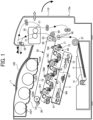
- the image forming apparatus 1 is a tandem-type color printer.
- the image forming apparatus 1 includes a bottle housing 101 in an upper portion of the image forming apparatus 1.
- the bottle housing 101 accommodates four toner bottles 102Y, 102M, 102C, and 102K containing fresh yellow, magenta, cyan, and black toners, respectively, and is detachably attached to the bottle housing 101 for replacement.
- an intermediate transfer unit 85 is disposed under the bottle housing 101. Facing an intermediate transfer belt 78 of the intermediate transfer unit 85, image forming devices 4Y, 4M, 4C, and 4K are arranged side by side to form toner images of yellow, magenta, cyan, and black, respectively.
- the image forming devices 4Y, 4M, 4C, and 4K include photoconductor drums 5Y, 5M, 5C, and 5K, respectively.
- Each of the photoconductor drums 5Y, 5M, 5C, and 5K is surrounded by a charger 75, a developing device 76, a cleaner 77, and a discharger.
- Image forming processes including a charging process, an exposure process, a developing process, a primary transfer process, and a cleaning process are performed on an outer circumferential surface of each of the photoconductor drums 5Y, 5M, 5C, and 5K, forming yellow, magenta, cyan, and black toner images on the photoconductor drums 5Y, 5M, 5C, and 5K, respectively.
- a motor drives and rotates the photoconductor drums 5Y, 5M, 5C, and 5K clockwise in FIG. 1 .
- the chargers 75 uniformly charge the surfaces of the photoconductor drums 5Y, 5M, 5C, and 5K, respectively, which is referred to as the charging process.
- each of the photoconductor drums 5Y, 5M, 5C, and 5K reaches an irradiation position at which an exposure device 3 irradiates and scans the photoconductor drums 5Y, 5M, 5C, and 5K with laser beams L, irradiating and scanning the photoconductor drums 5Y, 5M, 5C, and 5K with the laser beams L forms electrostatic latent images according to yellow, magenta, cyan, and black image data in the exposure process.
- the irradiated and scanned outer circumferential surface of each of the photoconductor drums 5Y, 5M, 5C, and 5K reaches a developing position at which the developing device 76 is disposed opposite each of the photoconductor drums 5Y, 5M, 5C, and 5K, and the developing device 76 develops the electrostatic latent image formed on the respective photoconductor drums 5Y, 5M, 5C, and 5K, thus forming yellow, magenta, cyan, and black toner images on the photoconductor drums 5Y, 5M, 5C, and 5K in the developing process.
- the yellow, magenta, cyan, and black toner images formed on the photoconductor drums 5Y, 5M, 5C, and 5K reach primary transfer nips formed between the photoconductor drums 5Y, 5M, 5C, and 5K and the intermediate transfer belt 78 by four primary transfer bias rollers 79Y, 79M, 79C, and 79K pressed against the four photoconductor drums 5Y, 5M, 5C, and 5K via the intermediate transfer belt 78, respectively, and the yellow, magenta, cyan, and black toner images are primarily transferred onto the intermediate transfer belt 78 in a primary transfer process. After the primary transfer process, residual toner failed to be transferred onto the intermediate transfer belt 78 remains on the photoconductor drums 5Y, 5M, 5C, and 5K slightly.
- the residual toner on each of the photoconductor drums 5Y, 5M, 5C, and 5K reaches a cleaning position at which the cleaner 77 is disposed opposite each of the photoconductor drums 5Y, 5M, 5C, and 5K, and a cleaning blade of the cleaner 77 mechanically collects the residual toner from each of the photoconductor drums 5Y, 5M, 5C, and 5K in the cleaning process.
- each of the photoconductor drums 5Y, 5M, 5C, and 5K reaches a discharging position at which the discharger is disposed opposite each of the photoconductor drums 5Y, 5M, 5C, and 5K, and the discharger eliminates residual potential from each of the photoconductor drums 5Y, 5M, 5C, and 5K.
- the yellow, magenta, cyan, and black toner images formed on the photoconductor drums 5Y, 5M, 5C, and 5K in the developing process are primarily transferred onto an outer circumferential surface of the intermediate transfer belt 78 such that the yellow, magenta, cyan, and black toner images are superimposed on a same position on the intermediate transfer belt 78.
- a color toner image is formed on the intermediate transfer belt 78.
- the intermediate transfer unit 85 includes the intermediate transfer belt 78, the four primary transfer bias rollers 79Y, 79M, 79C, and 79K, a secondary transfer backup roller 82, a cleaning backup roller 83, a tension roller 84, and an intermediate transfer belt cleaner 80.
- the intermediate transfer belt 78 is stretched taut across and supported by the three rollers, that is, the secondary transfer backup roller 82, the cleaning backup roller 83, and the tension roller 84.
- One of the three rollers, that is, the secondary transfer backup roller 82 drives and rotates the intermediate transfer belt 78 in a rotation direction indicated by an arrow in FIG. 1 .
- the four primary transfer bias rollers 79Y, 79M, 79C, and 79K sandwich the intermediate transfer belt 78 together with the four photoconductor drums 5Y, 5M, 5C, and 5K, respectively, thus forming the four primary transfer nips between the intermediate transfer belt 78 and the photoconductor drums 5Y, 5M, 5C, and 5K.
- Each of the primary transfer bias rollers 79Y, 79M, 79C, and 79K is applied with a primary transfer bias having a polarity opposite the polarity of the electric charge of toner.
- the intermediate transfer belt 78 is moved in the direction indicated by the arrow in FIG. 1 and sequentially passes through the primary transfer nips formed by the primary transfer bias rollers 79Y, 79M, 79C, and 79K.
- the yellow, magenta, cyan, and black toner images on the photoconductor drums 5Y, 5M, 5C, and 5K are primarily transferred to and superimposed on the intermediate transfer belt 78, thereby forming the color toner image.
- the intermediate transfer belt 78 bearing the color toner image reaches a position opposite a secondary transfer roller 89.
- the secondary transfer backup roller 82 and the secondary transfer roller 89 press against each other via the intermediate transfer belt 78, and the contact portion therebetween is referred to as a secondary transfer nip below.
- the four color toner image formed on the intermediate transfer belt 78 is transferred onto the sheet P conveyed to the position of the secondary transfer nip. At this time, untransferred toner that is not transferred onto the sheet P remains on the surface of the intermediate transfer belt 78.
- the intermediate transfer belt 78 reaches a position opposite the intermediate transfer belt cleaner 80. At the position, the intermediate transfer belt cleaner 80 collects the untransferred toner from the intermediate transfer belt 78.
- the sheet P conveyed through the secondary transfer nip is conveyed from a sheet feeder 12 disposed in a lower portion of the body of the image forming apparatus 1 through a feed roller 97, a registration roller pair 98 (e.g., a timing roller pair).
- the sheet feeder 12 contains a stack of multiple sheets P such as sheets of paper stacked on top of one another.
- the feed roller 97 rotates counterclockwise in FIG. 1 , the feed roller 97 feeds an uppermost sheet P in the sheet feeder 12 to a roller nip between the registration roller pair 98.
- the registration roller pair 98 stops rotating temporarily, stopping the sheet P with a leading edge of the sheet P nipped in the roller nip between the registration roller pair 98. Subsequently, the registration roller pair 98 rotates to convey the sheet P to the secondary transfer nip, timed to coincide with the arrival of the color toner image on the intermediate transfer belt 78. Thus, the desired color toner image is transferred onto the sheet P.
- the sheet P is conveyed to a fixing device 20.
- a fixing belt 22 and a pressure roller 31 apply heat and pressure to the sheet P to fix the transferred color toner image on the sheet P, which is referred to as a fixing process.
- the sheet P bearing the fixed toner image is conveyed through a roller nip formed by an output roller pair 99 and ejected by the output roller pair 99 onto an outside of the image forming apparatus 1.
- the sheets P ejected by the output roller pair 99 are sequentially stacked as output images on a stack section 100.
- the following describes a configuration and operation of the fixing device 20 as the heating device incorporated in the image forming apparatus 1.
- the fixing device 20 as the heating device includes a fixing belt 22 as a belt, a stay 30 as a reinforcement, a planar heater 24 as a heater, a holder 23, a pair of flanges 42, a pressure roller 31 as a pressure rotator, and a temperature sensor 40 as a temperature detector.
- the fixing device 20 can be attached to and detached from the body of the image forming apparatus 1 by rotating an opening and closing cover 110 (see FIG. 1 ) on a hinge 110a in the body of the image forming apparatus 1.
- the fixing belt 22, the planar heater 24, the holder 23, the stay 30, and the pair of flanges 42 are assembled to form a fixing sub-assembly unit 21 as a single unit (see FIG. 4 ).
- the fixing belt 22 as a fixing rotator is an endless belt that is in contact with an outer circumferential surface of the pressure roller 31 and driven to rotate by rotation of the pressure roller 31.
- the fixing belt 22 is a thin, flexible endless belt driven to rotate counterclockwise in FIG. 2 , that is, in a rotation direction indicated by an arrow in FIG. 2 .
- the fixing belt 22 includes a base layer having an inner circumferential surface (i.e., a sliding contact surface of the fixing belt 22 sliding over the planar heater 24), an elastic layer coating the base layer, and a release layer coating the elastic layer, which define a total thickness of the fixing belt 22 not greater than 1 mm.
- the base layer of the fixing belt 22 has a thickness in a range of from 30 ⁇ m to 50 ⁇ m and is made of metal, such as nickel or stainless steel, or resin such as polyimide.
- the elastic layer of the fixing belt 22 has a thickness of 100 ⁇ m to 300 ⁇ m and is made of rubber such as silicone rubber, foamable silicone rubber, or fluoro rubber.
- the elastic layer absorbs slight surface asperities of the fixing belt 22 at a fixing nip formed between the fixing belt 22 and the pressure roller 31, facilitating even heat conduction from the fixing belt 22 to the color toner image T on the sheet P and thereby preventing formation of an orange peel image on the sheet P.
- the release layer of the fixing belt 22 has a thickness in a range of from 5 ⁇ m to 50 ⁇ m and is made of material such as tetrafluoroethylene-perfluoroalkyl vinyl ether copolymer (PFA), polytetrafluoroethylene (PTFE), polyimide, polyether imide, and polyether sulfone (PES).
- PFA tetrafluoroethylene-perfluoroalkyl vinyl ether copolymer
- PTFE polytetrafluoroethylene
- PES polyether sulfone
- the planar heater 24, the holder 23 and the stay 30 are disposed inside a loop of the fixing belt 22, the planar heater 24, the holder 23 and the stay 30 are disposed
- the planar heater 24 is disposed so as to extend in a width direction that is a direction perpendicular to the surface of the paper on which FIG. 2 is drawn.
- the planar heater 24 contacts the inner circumferential surface of the fixing belt 22.
- the planar heater 24 is pressed against the pressure roller 31 via the fixing belt 22 to form the fixing nip through which the sheet P is conveyed.
- the planar heater 24 is disposed inside the loop formed by the fixing belt 22 such that the inner circumferential surface of the fixing belt 22 slides over the planar heater 24. Pressing the planar heater 24 against the pressure roller 31 via the fixing belt 22 forms the fixing nip through which the sheet P is conveyed.
- the planar heater 24 functions as a nip formation pad that is a member forming the fixing nip.
- the planar heater 24 may include a surface layer or a sheet made of low friction material such as PTFE on the surface of the planar heater 24 to reduce sliding friction between the fixing belt 22 and the planar heater 24.
- the holder 23 holds the planar heater 24.
- the holder 23 has a recess 23a (see FIGS. 12A, 12B , 13A, and 13B ).
- the planar heater 24 is fitted into the recess 23a to hold the planar heater 24 in the width direction.
- the stay 30 holds the holder 23 holding the planar heater 24.
- the fixing device 20 includes a housing 43 including a first frame 43a.
- the first frame 43a holds both ends of the stay 30 holding the planar heater 24 and the holder 23 in the width direction (see FIG. 3 ) via the flanges 42.
- the planar heater 24 (the resistor pattern 26) disposed inside the loop of the fixing belt 22 directly heats the fixing belt 22.
- the outer circumferential surface of the fixing belt 22 heated by the planar heater 24 heats the toner image T on the sheet P.
- the output of the planar heater 24 is controlled based on the temperature of the outer circumferential surface of the fixing belt 22 detected by the temperature sensor 40.
- the temperature sensor 40 is a thermopile or a thermistor disposed opposite the outer circumferential surface of the fixing belt 22.
- the planar heater 24 controlled as described above heats the fixing belt 22 to a desired fixing temperature.
- the fixing device 20 in the present embodiment includes the temperature sensor 40 that directly detects the fixing temperature of the fixing belt 22, the fixing device 20 may include a temperature sensor such as a thermostat or a thermistor that detects the surface temperature of the planar heater 24 to indirectly detect the fixing temperature of the fixing belt 22 (see FIG. 21 ).
- the temperature sensor in contact with the planar heater 24 can also function as a safety device for preventing an excessive temperature rise in the planar heater 24.
- the pair of flanges 42 as guides guide both ends of the inner circumferential surface of the fixing belt 22 in the width direction of the fixing belt 22 such that the fixing belt 22 maintains a substantially cylindrical posture.
- the two flanges 42 are made of a heat-resistant resin material and are fitted into both sides of the housing 43 in the width direction of the housing 43 of the fixing device 20 so that the flanges 42 can slide and move along both sides.
- Each of the flanges 42 includes a tubular portion 42a and a restricting member 42b as a stopper.
- the tubular portion 42a holds the fixing belt 22 to maintain the substantially cylindrical posture thereof.
- the restricting member 42b restricts the motion or skew of the fixing belt 22 in the width direction thereof.
- the fixing device 20 includes compression springs 52 as biasing members. Biasing forces of the compression springs 52 press the flanges 42, respectively. As a result, the fixing belt 22, the planar heater 24, the holder 23, and the stay 30 are pressed against the pressure roller 31 by the biasing forces.
- the flanges 42 support both end portions of the fixing belt 22 in the width direction of the fixing belt 22 except for both end portions corresponding to the fixing nip so that the planar heater 24 can form the fixing nip.
- the inner circumferential surface of the fixing belt 22 is loosely contacted only by the flanges 42 at respective ends of the fixing belt 22 in the width direction thereof and the planar heater 24.
- the fixing device 20 includes the stay 30 that is disposed inside the loop of the fixing belt 22 so as to be in contact with the pressure roller 31 via the holder 23, the planar heater 24, and the fixing belt 22.
- the stay 30 reinforces the holder 23 and the planar heater 24 forming the fixing nip to enhance the mechanical strength of the holder 23 and the planar heater 24.
- the housing 43 holds the stay 30 via the flanges 42. (See FIGS. 2 , 5 , 8 , 12A, and 12B )
- the stay 30 receiving the pressure from the pressure roller 31 via the holder 23, the planar heater 24, and the fixing belt 22 prevents a disadvantage that the pressure from the pressure roller 31 largely deforms the planar heater 24 (and the holder 23) at the fixing nip.
- the stay 30 is made of metal having an increased mechanical strength, such as stainless steel or iron, to achieve the above-described function.
- the holder 23 may be made of resin or metal.
- the holder 23 is made of resin that has rigidity to prevent the holder 23 from bending even if the holder 23 receives pressure from the pressure roller 31, and the resin preferably has heat resistance and thermal insulation.
- the resin may be liquid crystal polymer (LCP), polyamide imide (PAI), polyether sulfone (PES), polyphenylene sulfide (PPS), polyether nitrile (PEN), and polyether ether ketone (PEEK).
- LCP liquid crystal polymer
- PAI polyamide imide
- PES polyether sulfone
- PPS polyphenylene sulfide
- PEN polyether nitrile
- PEEK polyether ether ketone
- liquid crystal polymer (LCP) is used as the material of the holder 23.
- the pressure roller 31 as the pressure rotator includes a cored bar 32 (serving as an axial portion) and an elastic layer 33 coating the cored bar 32.
- the pressure roller 31 is driven and rotated clockwise in FIG. 2 by a drive motor.
- the cored bar 32 of the pressure roller 31 has a hollow structure made of metal.
- the elastic layer 33 of the pressure roller 31 is made of material such as foamable silicone rubber, silicone rubber, or fluoro rubber.
- a thin release layer made of PFA or PTFE may be provided on the surface of the elastic layer 33.
- the pressure roller 31 is pressed against the fixing belt 22 to form a desired nip between the fixing belt 22 and the pressure roller 31.
- a gear 45 is attached to the pressure roller 31 and engages a driving gear of the drive motor so that the pressure roller 31 is driven and rotated clockwise in FIG. 2 , that is, a direction indicated by the arrow in FIG. 2 .
- Both ends of the pressure roller 31 in the width direction of the pressure roller 31 are rotatably supported by the housing 43 of the fixing device 20 through bearings, respectively.
- the housing 43 as the frame of the fixing device 20 in the present embodiment includes two frames that are the first frame 43a and a second frame 43b.
- the first frame 43a and the second frame 43b can be separated from each other.
- the first frame 43a functions as a main portion of the housing 43 and has a substantially U-shaped cross section.
- the first frame 43a has guides 43x that fit into grooves 42b1 formed in the flanges 42 of the fixing sub-assembly unit 21 and bearing portions to receive a shaft of the pressure roller 31.
- the pressure roller 31 and the fixing sub-assembly unit 21 are assembled to the first frame 43a.
- the second frame 43b is a lid-shaped frame that is installed (joined) to the first frame 43a so as to cover the fixing sub-assembly unit 21.
- biasing members are interposed between the flanges 42 of the fixing sub-assembly unit 21 and the second frame 43b.
- the compression springs 52 function as biasing members that press the pair of flanges 42 against the pressure roller 31 as the pressure rotator.
- the planar heater 24 in the present embodiment includes a base 25, the resistor patterns 26 (the resistive heat generators), conductor patterns 27 (relay portions), power supply electrodes 28 as electrodes.
- the base 25 has a front surface facing the inner circumferential surface of the fixing belt 22 in the fixing nip. At least the front surface of the base 25 is made of an insulative material. In the present embodiment, the base 25 is entirely made of the insulative material (aluminum nitride (AlN) in the present embodiment).
- AlN aluminum nitride
- the resistor patterns 26 are formed on the front surface of the base 25. Similarly, the conductor patterns 27 are also formed on the front surface of the base 25. A current flows through the resistor pattern 26 (that is, energizing the resistor pattern 26), the resistance of the resistor pattern 26 generates heat, and the resistor pattern 26 functions as the resistive heat generator.
- the resistor pattern 26 is formed by applying and screen-printing a paste prepared to have a desired resistance value to the surface of the base 25 and baking the paste after screen-printing.
- Each of the conductor patterns 27 electrically couples between the resistor patterns 26 or between the resistor pattern 26 and the power supply electrode 28 to function as the relay portion that flows the current input from the power supply electrode 28 to the resistor pattern 26.
- the conductor pattern 27 is formed by applying and screen-printing a paste having high conductivity to the surface of the base 25 and baking the paste after screen-printing.
- the power supply electrode 28 is electrically coupled to the conductor pattern 27 and is formed to couple to an external terminal that is a contact 29a1 of a terminal 29a of a connector 29 (see FIG. 7 ). Accordingly, even when the surface layer having electrical insulating properties and low friction properties is formed on the entire surface of the planar heater 24, a part of the surface layer over the power supply electrode 28 is removed to expose the power supply electrode 28 and supply power to the power supply electrode 28.
- the power supply electrode 28 is made of a silver-based material such as silver (Ag) or silver palladium (AgPd) in order to reduce heat generation due to energization.
- the power supply electrode 28 is formed by screen-printing the material on the surface of the base 25 and baking the material after screen-printing.
- the connector 29 is mounted so as to sandwich an end of the holder 23 holding the planar heater 24 in the width direction. After the fixing sub-assembly unit 21 as illustrated in FIG. 3 is installed in the housing 43, the connector 29 is set on one end of the fixing sub-assembly unit 21 as illustrated in FIG. 12B .
- the connector 29 has a U-shaped cross sectional shape in a cross section orthogonal to the width direction.
- the connector 29 includes the terminals 29a disposed inside the U-shaped cross sectional shape.
- the contacts 29a1 of the terminals 29a are electrically connected to the power supply electrodes 28 of the planar heater 24.
- the above-described configuration enables the power supply in the body of the image forming apparatus 1 to supply the electric power to resistor patterns 26 of the planar heater 24 via harnesses 90, the terminals 29a, and the power supply electrodes 28.
- the connector 29 and the harnesses 90 are held by clamps on the outer surface of the housing 43 (the second frame 43b) of the fixing device 20.
- the image forming apparatus 1 includes a body side connector coupled to the power supply.
- the harnesses 90 are coupled to a second connector on the fixing device 20.
- the second connector is connected to and disconnected from the body side connector in conjunction with an operation of attaching and detaching the fixing device 20 to and from the body of the image forming apparatus 1.
- a power switch on the body of the image forming apparatus 1 supplies power to the planar heater 24, and the motor starts driving and rotating the pressure roller 31 clockwise in FIG. 2 , that is, in a direction indicated by an arrow in FIG. 2 . Due to friction between the pressure roller 31 and the fixing belt 22, rotating the pressure roller 31 drives and rotates the fixing belt 22 counterclockwise in FIG. 2 .
- the sheet P is fed from the sheet feeder 12, and the color toner image is transferred onto the sheet P at the position of the secondary transfer roller 89.
- the sheet P bears an unfixed color image.
- the sheet P bearing the unfixed toner image T is conveyed in a direction indicated by an arrow Y10 while the sheet P is guided by a guide plate and enters the fixing nip formed between the fixing belt 22 and the pressure roller 31 pressed against the fixing belt 22.
- the stay 30 reinforces the planar heater 24 (and the holder 23).
- the toner image T is fixed on a surface of the sheet P under heat from the fixing belt 22 heated by the planar heater 24 and pressure exerted from the pressure roller 31 and the planar heater 24 (and the holder 23). Thereafter, the sheet P is ejected from the fixing nip and conveyed in a direction indicated by an arrow Y11 in FIG. 2 .
- the following describes a configuration and operation of the fixing device 20 as the heating device in detail.
- the fixing device 20 as the heating device includes the planar heater 24, the fixing belt 22, the pressure roller 31, the holder 23, the stay 30, the pair of flanges 42, the housing 43, the compression springs 52.
- the planar heater 24 has a substantially rectangular parallelepiped shape extending in the width direction that is the horizontal direction in FIG. 12 and the direction perpendicular to the paper surface on which FIGS. 2 , 11A, and 11B are drawn.
- the planar heater 24 heats the fixing belt 22, and the fixing belt 22 heats the toner image to fix the toner image on the face of the sheet P.
- the pressure roller 31 as the pressure rotator is pressed against the planar heater 24 via the fixing belt 22 to form the fixing nip in which the sheet P is conveyed.
- the holder 23 holds the entirety of the planar heater 24 extending in the width direction.
- the holder 23 in the present embodiment is made of resin.
- the stay 30 holds the holder 23 and also functions as a reinforcement to reinforce the mechanical strength of the holder 23.
- the stay 30 in the present embodiment is made of metal.
- the stay 30 has a U-shaped cross section.
- the stay 30 has projections at both ends in the width direction, and the projections disposed at the end of the stay 30 are fitted into the flange 42 as illustrated in FIG. 8 .
- the pair of flanges 42 is configured to hold both ends of the stay 30 in the width direction and to hold both ends of the fixing belt 22 in the width direction.
- the housing 43 holds the pair of flanges 42 so as to be movable in the horizontal direction in FIGS. 2 and 15 . Moving the flange 42 in the horizontal direction changes the distance between the flange 42 and the pressure roller 31.
- the compression springs 52 function as biasing members that bias the pair of flanges 42 in a direction approaching the pressure roller 31 as the pressure rotator.
- the flange 42 in the present embodiment includes the tubular portion 42a and the restricting member 42b that have a cutout 42c.
- the restricting member 42b has grooves 42b 1 and includes a bridging portion 42b2.
- the tubular portion 42a of the flange 42 faces the inner circumferential surface of the fixing belt 22 to maintain the substantially tubular posture of the fixing belt 22. Since the tubular portion 42a has the cutout 42c, the sectional shape of the outer peripheral surface of the tubular portion 42a is not a perfect circle and is an arc.
- the restricting member 42b of the flange 42 contacts an edge of the fixing belt 22 to restrict the movement of the fixing belt 22 in the width direction.
- the restricting member 42b has a wall that is adjacent to the tubular portion 42a and sufficiently larger than the tubular portion 42a so that the wall contacts the edge of the fixing belt 22.
- the cutout 42c of the flange 42 extends over the tubular portion 42a and the restricting member 42b and is formed at a portion corresponding to the fixing nip.
- the cutout 42c functions as a clearance portion so that the contact between the fixing belt 22 and the pressure roller 31 favorably forms the fixing nip.
- the bridging portion 42b2 bridges and closes the cutout 42c at a position adjacent to the outer face of the restricting member 42b in the width direction (i.e., the right end of the restricting member 42b in FIG. 10 , a face opposite to the inner face of the restricting member 42b adjacent to the tubular portion 42a, the face away from the fixing belt 22).
- the inner portion of the restricting member 42b in the width direction has a substantially U-shaped cross section formed by the cutout 42c
- the outer portion of the restricting member 42b in the width direction has a substantially square cross section formed by the bridging portion 42b2.
- the position of the bridging portion 42b2 is outside the fixing nip between the fixing belt 22 and the pressure roller 31 and outside the tubular portion 42a.
- the flange 42 including the bridging portion 42b2 which is formed as described above, is less likely to cause deformation due to resin-molding (deformation in which both tips of the U shape are closed, see the flange 142 in FIG. 16 ) than the flange not including the bridging portion 42b2. Further, the flange 42 including the bridging portion 42b2 has a larger mechanical strength than the flange not including the bridging portion 42b2.
- the flange 42 including the bridging portion 42b2 can prevent the disadvantage that the planar heater 24 is set to be deviated from the fixing nip, does not typically function, and causes a fixing failure as in the comparative example illustrated in FIG. 16 .
- the planar heater 24 is correctly set to face the fixing nip as illustrated in FIG. 15 and correctly functions.
- the flange 42 may include a taper 42b2T having a taper angle of about 30° to 60° on a wall face downstream in a mounting direction (the left wall of the flange in FIG. 12C ).
- the taper 42b2T enhances the workability when the flange 42 in the present embodiment is relatively moved in the width direction to assemble the flange 42 to the sub-assembly of the holder 23, the stay 30, and the planar heater 24 that is wrongly assembled to the holder 23.
- the taper 42b2T of the flange 42 is set to be larger than the thickness of the planar heater 24.
- the restricting member 42b of the flange 42 has grooves 42b1 formed on portions adjacent to both ends of the bridging portion 42b2 (i.e., an upper portion and a lower portion of the restricting member 42b in FIG. 10 ).
- the guides 43x of the housing 43 slide on the grooves 42b1 and fitted to the grooves 42b 1.
- the compression spring 52 is disposed between the second frame 43b and each of the flanges 42.
- the compression springs 52 press the flanges 42, and the flanges 42 move along the guides 43x (that slide on the grooves 42b1) in a pressing direction to press the fixing belt 22 against the pressure roller 31.
- the fixing device 20 of the present embodiment is designed to have a gap M between the bridging portion 42b2 and the planar heater 24 in a direction orthogonal to the width direction and a sheet conveyance direction that is smaller than a depth N of the recess 23a in the holder 23 into which the planar heater 24 is fitted (M ⁇ N).
- the depth N may be referred to as a heater restricting height.
- the sheet conveyance direction is defined as the direction in which the sheet P is conveyed in the fixing device 20.
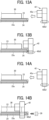
- the bridging portion 42b2 of the flange 42 interferes with the end face of the planar heater 24 that is not correctly set on the holder 23 and is separated from the bottom of the recess 23a (in other words, rides on the end of the holder 23) as illustrated in FIGS. 11B and 13B .
- the worker who assembles the flange 42 to the sub-assembly including the planar heater 24 and the holder 23 can notice that the planar heater 24 is not correctly set on the holder 23.
- the "gap between the bridging portion and the planar heater” is defined as a gap measured under a condition that the belt such as the fixing belt 22 is pressed against the pressure rotator such as the pressure roller 31 to form a nip.
- the "gap between the bridging portion and the planar heater” is measured under the condition that the planar heater, the holder, and the stay are moved to be close to the flange.
- the depth (N) of the recess in the holder into which the planar heater is fitted is defined as the deepest depth if the depth (N) varies depending on a position in the recess.
- the depth (N) is measured more preferably at a position facing the flange or at a position outside of the flange than at the position of the center of the holder in the width direction.
- the above-described structure can prevent the disadvantage that the flange 42 is assembled to the sub-assembly in which the planar heater 24 is not correctly set on the holder 23 when the flange 42 is relatively moved to the sub-assembly in which the planar heater 24, the holder 23, and the stay 30 are assembled to assemble the flange 42 to the sub-assembly because the gap M between the bridging portion 42b2 and the planar heater 24 is smaller than the depth N of the recess 23a in the holder 23.
- the above-described structure also prevents the disadvantage that the planar heater 24 or the holder 23 is damaged by one end of the planar heater 24 that rides on the end of the holder and contacts the pressure roller 31 or the holder 23 with a strong force when the nip is formed.
- the bridging portion 42b2 functions to prevent the planar heater 24 from falling off from the fixing sub-assembly unit 21 even when some forces are applied to the fixing sub-assembly unit 21 by releasing (or reducing) the pressure of the pressure roller 31 with respect to the fixing belt 22 after the fixing device 20 is incorporated in the image forming apparatus.
- FIGS. 14A and 14B are diagrams illustrating the action to attach a flange according to a comparative example to the fixing sub-assembly unit.
- the gap M between the bridging portion 42b2 and the planar heater 24 is larger than the depth N of the recess 23a in the holder 23 (M > N).
- the connector 29 cannot be attached so as to sandwich the planar heater 24 and the holder 23.
- the planar heater 24, the holder 23, and the connector 29 may collide with each other and be damaged.
- the connector 29 includes the terminals 29a contacting the power supply electrodes 28 as the electrodes of the planar heater 24.
- the connector 29 is mounted on the planar heater 24 and the holder 23 in a predetermined mounting direction that is the direction indicated by the arrow in FIG. 7 and the direction orthogonal to the width direction so as to sandwich the planar heater 24 and the holder 23.
- W the thickness of the planar heater 24 - the depth N of the recess 23a.
- the flange 42 is designed to be longer than the holder 23 in the sheet conveyance direction of the sheet P that is the vertical direction in FIGS. 11A and 11B .
- the thickness of the flange 42 is thicker than the thickness of the holder 23. The above-described configuration enables the flanges 42 to stably hold the holder 23 holding the planar heater 24 via the stay 30.
- the fixing device 20 includes the fixing sub-assembly unit 21 in which the fixing belt 22, the planar heater 24, the holder 23, the stay 30, and the pair of flanges 42 are unitized (sub-assembled) to enhance the entire assembly workability.
- the above-described structure effectively exhibits the effect of providing the bridging portion 42b2 in the flange 42 and the effect of configuring the gap M between the bridging portion 42b2 and the planar heater 24 to be smaller than the depth N of the recess 23a in the holder 23 as described above at the time of assembling the fixing sub-assembly unit 21.
- the fixing device 20 Similar to the fixing device illustrated in FIGS. 12A and 12B , the fixing device 20 according to the first modification includes the connector 29 disposed in the vicinity of the flange 42.
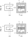
- the bridging portion 42b2 of the flange 42 in the fixing device 20 has projections 42x to restrict the movement of the planar heater 24 in the horizontal direction in FIG. 17 that is a direction orthogonal to the mounting direction of the connector 29 that is the direction indicated by the white arrow in FIG. 17 .
- the projection 42x is a boss having a hemispherical tip and is formed so as to project from an inner face of the bridging portion 42b2, the inner face facing the planar heater 24, toward the planar heater 24.
- the projection 42x in the present embodiment does not contact the planar heater 24.
- the projections 42x disposed as described above prevent the heater from separating from the heater holder by a certain amount or more.
- the projections 42x are disposed at positions different from contacting positions at which the contacts 29a1 of the terminals 29a of the connector 29 are in contact with the power supply electrodes 28. Attaching the flange 42 to the planar heater 24 as illustrated in FIGS. 12A and 12B is likely to cause the projection 42x to come into contact with the power supply electrode 28 and damage the power supply electrode 28. The above-described structure prevents the disadvantage caused by the damage of the power supply electrode 28 of the planar heater 24.
- two projections 42x are formed so as to sandwich a portion indicated by an alternate long and short dash line in FIG. 17 at which the terminals 29a are in contact with the power supply electrodes 28 in the mounting direction indicated by the white arrow.
- two projections 42x are disposed so as to sandwich the range X in which the terminals 29a are disposed.
- the contacting positions of the terminals 29a contacting the electrodes 28 in the mounting direction are between the two projections 42x in the mounting direction.
- the bridging portion 42b2 may have one projection 42x formed downstream from the range X in the mounting direction indicated by the white arrow.
- the one projection 42x may be downstream from the contact positions of the terminals 29a contacting the electrodes 28 in the mounting direction.
- the holder 23 in the first modification may have notches 23a1 (clearance portions) corresponding to the projections 42x in a wall of the holder 23 at a widthwise end of the holder 23 to avoid interference between the projections 42x and the holder 23 caused by attaching the flange 42 to the holder 23.
- the fixing device 20 in the second modification includes a flat spring 42z as an elastic body disposed on the flange 42.
- the flat spring 42z is disposed on the bridging portion 42b2 and functions as the elastic body pressing the planar heater 24 to fit into the recess 23a of the holder 23 when the flange 42 is relatively moved and attached to the holder 23 holding the planar heater 24.
- the flat spring 42z is formed so as to apply a force (an elastic force) in the direction indicated by an arrow in FIG. 19B to the planar heater 24 when the flat spring 42z comes into contact with the planar heater 24 in the process of attaching the flange 42 to the holder 23.
- the flat spring 42z pushes the planar heater 24 riding on the holder 23 (in other words, the planar heater 24 floating from the holder 23) into the recess 23a in the process of attaching the flange 42 to the holder 23 as illustrated in FIGS. 19A to 19C . Then the planar heater 24 is correctly set to the holder 23.
- the flat spring 42z in the second modification is preferably disposed at a position different from the contacting positions at which the contacts 29a1 of the terminals 29a of the connector 29 are in contact with the power supply electrodes 28. Attaching the flange 42 to the holder 23 holding the planar heater 24 as illustrated in FIGS. 19A to 19C is likely to cause the flat spring 42z to come into contact with the power supply electrode 28 and damage the power supply electrode 28. The above-described structure prevents the disadvantage caused by the damage of the power supply electrode 28 of the planar heater 24.
- an elastic portion 42b20 functioning as an elastic body in the same manner as the flat spring 42z in FIG. 19 may be integrally formed on the bridging portion 42b2 of the flange 42.
- the elastic portion 42b20 may be a resin spring integrally molded with the flange 42.
- the elastic portion 42b20 may be made of rubber and attached to the flange 42.
- the fixing device 20 includes thermostats 49 (or thermistors) arranged at intervals in the width direction to detect surface temperatures of the planar heater 24.
- the thermostats 49 detect the surface temperatures of the planar heater 24 to indirectly detect the fixing temperature of the fixing belt 22 and control the fixing temperature, in addition to function as a safety device for preventing an excessive temperature rise in the planar heater 24.
- the thermostats 49 also function as pushers to push the planar heater 24 to the pressure roller 31 as the pressure rotator.
- the thermostat 49 is configured to bias and contact the upper face of the planar heater 24 in FIG. 21 , that is, the face opposite to another face forming the nip, by a predetermined contact pressure.
- the fixing device 20 may include one thermostat 49 on one end of the planar heater 24 in the width direction.
- the connector 29 is preferably disposed at one end of the holder 23 closer to the thermostat 49 than the other end of the holder 23 (that is, the right side portion of the holder 23 in FIG. 21B ).
- the thermostat 49 functioning as the pusher and the bridging portion 42b2 of the flange 42 generates a force pushing the planar heater 24 to the recess 23a of the holder 23, which enhances the fitting performance of the connector 29 mounted so as to sandwich the planar heater 24 and the holder 23.
- the flange 42 may have the taper formed on the downstream side wall of the flange 42 in the mounting direction of the flange 42 to enhance the mounting performance of the flange 42.
- the flange 42 that is set on one end of the holder 23 closer to the thermostat 49 than the other end of the holder 23 preferably has the taper larger than a taper of the flange 42 set on the other end of the holder 23.
- a force of the thermostat 49 functioning as the pusher pushes one end of the planar heater 24 that is closer to the thermostat 49 than the other end of the planar heater 24 and separates one end of the planar heater 24 from the holder 23 farther than the other end of the planar heater 24, which is likely to cause difficulty to attach the flange 42 to the holder 23.
- a thermistor may be used as the pusher.
- the flange 42 in the fixing device 20 as the heating device according to the fourth modification has a pair of facing portions 42w that face the bridging portion 42b2 via both ends of the holder 23 in a short-side direction of the holder 23 (that are both ends of the holder 23 in the vertical direction in FIG. 22 ).
- both ends of the holder 23 in the short-side direction of the holder 23 that is the vertical direction in FIG. 22 are sandwiched between the bridging portion 42b2 and the facing portions 42w with a clearance therebetween.
- the pair of facing portions 43w are formed such that a sectional shape of the flange 42 having a space to set the holder 23 is a substantially convex shape.
- the pair of facing portions 42w function as holder restricting portions that restrict the movement of the holder 23 in the short-side direction.
- the bridging portion 42b2 of the flange 42 interferes with the end face of the planar heater 24 that is not correctly set on the holder 23 and is separated from the bottom of the recess 23a.
- the worker who assembles the flange 42 to the sub-assembly including the planar heater 24 and the holder 23 can notice that the planar heater 24 is not correctly set on the holder 23.
- FIG. 23 is a side view of a flange 42 according to a comparative example of the flange 42 of FIG. 22 .
- the flange 42 in FIG. 23 has one facing portion 42w facing one end of the holder 23 in the short-side direction of the holder 23 and no facing portion facing the other end of the holder 23 in the short-side direction of the holder 23.
- the planar heater 24 is not correctly set and floats from the holder 23
- the holder 23 can change the posture to be inclined and not be fixed, and the flange 42 can be assembled to the holder 23.
- the bridging portion 42b2 of the flange 42 does not interfere with the end face of the planar heater 24, and the worker who assembles the flange to the fixing sub-assembly unit cannot notice that the planar heater 24 is not correctly set on the holder 23. For this reason, it is useful to form the pair of facing portions 42w in the flange 42 as illustrated in FIG. 22 .
- the clearance between the facing portion 42w and the holder 23 is designed in consideration of thermal expansions of related members so that the facing portion 42w does not contact the holder 23 even when the planar heater 24 generates heat (even when the fixing device 20 is in operation).
- the clearance between the facing portion 42w and the holder 23 is designed so that each of the pair of facing portions 42w is separated from the holder 23 during heat generation of the planar heater. Designing the clearance as described above can prevent the disadvantage that the facing portion 42w and the holder 23 are deformed by contacting each other during the operation of the fixing device 20 (during the fixing process).
- the fixing device 20 as the heating device according to the fifth modification includes a thermal equalizer 60, and the holder 23 holds the planar heater 24 via the thermal equalizer 60.
- the thermal equalizer 60 is a plate made of a high thermal conductive material such as aluminum, copper, silver, graphene, or graphite and is fitted to the recess 23a of the holder 23 together with the planar heater 24.
- the thermal equalizer 60 is formed so as to be in contact with substantially the entire surface of the planar heater 24.
- the thermal equalizer 60 disposed as described above reduces temperature unevenness (heating unevenness) in the planar heater 24 itself and the fixing belt 22 heated by the planar heater 24.
- the fixing device 20 may include second thermal equalizers 61 made of the high thermal conductive material that is the same material of the thermal equalizer 60 in addition to the thermal equalizer 60 disposed in the recess 23a and interposed between the holder 23 and the planar heater 24 as illustrated in FIG. 24B .
- the second thermal equalizers 61 are interposed between the thermal equalizer 60 and the holder 23.
- the planar heater 24 includes the resistor patterns 26 such as the resistive heat generators arranged in the width direction
- each of the second thermal equalizer 61 is arranged so as to cover the ends of the adjacent resistor patterns 26 and the gap between the adjacent resistor patterns 26 as illustrated in FIG. 24B .
- Graphene is a flaky powder. Graphene has a planar hexagonal lattice structure of carbon atoms, as illustrated in FIG. 25 .
- the graphene sheet is typically a single layer.
- the graphene sheet may contain impurities in a single layer of carbon or may have a fullerene structure.
- the fullerene structures are generally recognized as compounds including an even number of carbon atoms, which form a cage-like fused ring polycyclic system with five and six membered rings, including, for example, C60, C70, and C80 fullerenes or other closed cage structures having three-coordinate carbon atoms.
- Graphene sheets are artificially made by, for example, a chemical vapor deposition (CVD) method.
- the graphene sheet is commercially available.
- the size and thickness of the graphene sheet or the number of layers of the graphite sheet described below are measured by, for example, a transmission electron microscope (TEM).
- TEM transmission electron microscope
- Graphite obtained by multilayering graphene has a large thermal conduction anisotropy.
- graphite has a crystal structure formed by layering a number of layers each having a condensed six membered ring layer plane of carbon atoms extending in a planar shape.
- adjacent carbon atoms in the layer are coupled by a covalent bond
- carbon atoms between layers are coupled by a van der Waals bond.
- the covalent bond has a larger bonding force than a van der Waals bond. Therefore, there is a large anisotropy between the bond between carbon atoms in a layer and the bond between carbon atoms in different layers.
- each of the thermal equalizer 60 and the second thermal equalizer 61 that are made of graphite has the heat transfer efficiency in the width direction larger than the heat transfer efficiency in the thickness direction of the thermal equalizer 60 and the second thermal equalizer 61 (that is, the vertical direction in FIGS. 24A and 24B ), reducing the heat transferred to the holder 23. Accordingly, the above-described structure can efficiently decrease the temperature unevenness of the planar heater 24 in the width direction and can minimize the heat transferred to the holder 23.
- Each of the thermal equalizer 60 and the second thermal equalizer 61 that are made of graphite are not oxidized at about 700 degrees or lower and has an excellent heat resistance.
- the physical properties and dimensions of the graphite sheet may be appropriately changed according to the function required for the thermal equalizer 60 and the second thermal equalizer 61.
- the anisotropy of the thermal conduction can be increased by using high-purity graphite or single-crystal graphite or increasing the thickness of the graphite sheet.
- Using a thin graphite sheet can reduce the thermal capacity of the fixing device 20 so that the fixing device 20 can perform high speed printing.
- a width of the thermal equalizer 60 or a width of the second thermal equalizer 61 may be increased in response to a large width of the fixing nip N or a large width of the planar heater 24.
- the number of layers of the graphite sheet is preferably 11 or more.
- the graphite sheet may partially include a single layer portion and a multilayer portion.
- the flange 42 can be correctly assembled to the sub-assembly in which the planar heater 24, the holder 23, the stay 30, and the thermal equalizer 60 are assembled.
- the flange 42 of the fixing device 20 as the heating device according to the sixth modification includes the tubular portion 42a having thick portions 42a1 facing each other to form the cutout 42c and the restricting member 42b having a stepped portion 42b3 formed in accordance with the end shape of the stay 30.
- the restricting member 42b of the flange 42 in the sixth modification also has the bridging portion 42b2 so as to close the cutout 42c at a position outside the tubular portion 42a in the width direction.
- the fixing device 20 is designed to have the gap M between the bridging portion 42b2 and the planar heater 24 that is smaller than the depth N of the recess 23a in the holder 23 into which the planar heater 24 is fitted.
- the above-described flange 42 can be also correctly assembled to the sub-assembly in which the planar heater 24, the holder 23, and the stay 30 are assembled.
- the fixing device 20 as the heating device according to the present embodiment includes the planar heater 24 extending in the width direction, the fixing belt 22 as the belt heated by the planar heater 24, the pressure roller 31 as the pressure rotator pressed against the planar heater 24 via the fixing belt 22 to form the nip in which the sheet P is conveyed, the holder 23 to hold the planar heater 24 in the width direction, the stay 30 holding the holder 23, the pair of flanges 42 to hold both ends of the stay 30 in the width direction and to hold both ends of the fixing belt 22 in the width direction, the housing 43 holding the pair of flanges 42 so as to be movable in a direction to change a distance between each of the pair of flanges 42 and the pressure roller 31, and the compression springs 52 as biasing members that bias the pair of flanges 42 in a direction approaching the pressure roller 31.
- At least one of the pair of flanges 42 includes the tubular portion 42a facing the inner circumferential surface of the fixing belt 22 and having the cutout 42c at a portion corresponding to the nip, the restricting member 42b contacting the edge of the fixing belt 22 to restrict the movement of the fixing belt 22 in the width direction and having the cutout 42c at a portion corresponding to the nip, and the bridging portion 42b2 disposed so as to close the cutout 42c at the position of the restricting member 42b outside the tubular portion 42a in the width direction.
- the fixing device 20 is designed to have the gap M between the bridging portion 42b2 and the planar heater 24 that is smaller than the depth N of the recess 23a in the holder 23 into which the planar heater 24 is fitted.
- the flange 42 can be correctly assembled to the sub-assembly in which the planar heater 24, the holder 23, and the stay 30 are assembled.
- the present invention is applied to the fixing device 20 using the pressure roller 31 as the pressure rotator, but the present invention can also be applied to a fixing device using a pressure belt as the pressure rotator.
- the present invention is applied to the fixing device 20 as the heating device installed in the electrophotographic image forming apparatus 1.
- the heating device to which the present invention is applied is not limited to this, and the present invention can be applied to a drying device (a device for drying ink on a sheet coated with ink) as a heating device installed in an inkjet image forming apparatus, a fixing device (a device for thermally bonding two laminate sheets) as a heating device installed in a laminate processing apparatus.
- the width direction is defined as a direction being perpendicular to a direction of conveying the sheet P and parallel to the axial direction of the fixing belt 22 and the pressure roller 31.
- the width direction is also the direction in which the heater extends.
- aspects of the present invention may be applicable to, for example, combinations of first to fifteenth aspects as follows.
- a heating device in a first aspect, includes a planar heater, a belt, a pressure rotator, a holder, a stay, a pair of flanges, a housing, and biasing members.
- the planar heater extends in a width direction and heats the belt.
- the pressure rotator is pressed against the planar heater via the belt to form a nip through which a sheet is conveyed.
- the holder has a recess to hold the planar heater in the width direction.
- the stay holds the holder.
- the pair of flanges hold both ends of the stay and both ends of the belt in the width direction. At least one of the pair of flanges includes a tubular portion, a restricting member, and a bridging portion.
- the tubular portion faces an inner circumferential surface of the belt and has a cutout at a portion corresponding to the nip.
- the restricting member is contactable with an edge of the belt to restrict movement of the belt in the width direction and has a cutout at a portion corresponding to the nip.
- the bridging portion bridges and closes the cutout of the restricting member.
- the bridging portion is outside the tubular portion in the width direction and has a gap with the planar heater smaller than a depth of the recess.
- the housing holds the pair of flanges movable with respect to the pressure rotator.
- the biasing members bias the pair of flanges toward the pressure rotator.
- the belt, the planar heater, the holder, the stay, and the pair of flanges in the heating device according to the first aspect form a single unit.
- the heating device according to the first aspect or the second aspect further includes a connector including terminals contacting electrodes of the planar heater, and the connector is mounted on the planar heater and the holder in a mounting direction, and the connector sandwiches the planar heater and the holder.
- the heating device further includes a projection projecting from the bridging portion toward the planar heater, and the projection is disposed at a position different from contacting positions of the terminals contacting the electrodes in the mounting direction.
- the heating device further includes another projection projecting from the bridging portion toward the planar heater, and said another projection is disposed at a position different from the contacting positions in the mounting direction.
- the contacting positions are between the projection and said another projection in the mounting direction
- the projection in the heating device according to the fourth aspect is disposed downstream from the contact positions.
- the flange in the heating device is longer than the holder in a conveyance direction of the sheet.
- the flange is thicker than the holder in a pressing direction of the pressure rotator pressing against the planar heater.
- the heating device according to any one of the first to seventh aspects further includes an elastic body disposed on the bridging portion of the flange to press the planar heater toward the recess of the holder.
- the heating device according to any one of the first to eighth aspects further includes a pusher pushing the planar heater to the pressure rotator.
- the pusher in the heating device according to the ninth aspect includes at least one of a thermistor or a thermostat to push one face of the planar heater opposite to another face forming the nip.
- the housing in the heating device has guides to guide the pair of flanges, and one of the guides slides on a groove formed in a portion of the restricting member adjacent to the bridging portion and is fitted to the groove.
- the flange in the heating device has a pair of facing portions facing both ends of the holder in a short-side direction of the holder, respectively, and each of the pair of facing portions faces the bridging portion.
- each of the pair of facing portions in the heating device according to the twelfth aspect is separated from the holder during heat generation of the planar heater.
- a fixing device includes the heating device according to any one of the first to thirteenth aspects.
- an image forming apparatus includes the heating device according to any one of the first to thirteenth aspects
Landscapes
- Physics & Mathematics (AREA)
- General Physics & Mathematics (AREA)
- Fixing For Electrophotography (AREA)
Abstract
A heating device (20) includes a planar heater (24), a belt (22), a pressure rotator (31) pressed against the planar heater (24) to form a nip, a holder (23) having a recess to hold the planar heater (24), a stay (30), a pair of flanges (42) holding both ends of the stay (30) and the belt (22), a housing (43), and biasing members (52). At least one of the pair of flanges (42) includes a tubular portion (42a) facing an inner surface of the belt (22) and having a cutout corresponding to the nip, a restricting member (42b) being contactable with an edge of the belt (22) and having a cutout corresponding to the nip, and a bridging portion (42b2) on the restricting member (42b) outside the tubular portion (42a). A gap between the bridging portion (42b2) and the planar heater (24) is smaller than a depth of the recess.
Description
- Embodiments of the present invention relate to a heating device such as a fixing device including a planar heater and an image forming apparatus including the heating device, such as a copier, a printer, a facsimile machine, or a multifunction peripheral having at least two of copying, printing, and facsimile functions.
- One type of heating device such as a fixing device in an image forming apparatus such as a copier or a printer in the related art uses a planar heater (a resistive heat generator) as a heater to heat a fixing belt (For example, see
Japanese Unexamined Patent Application Publication No. 2020-52347 - Specifically,
Japanese Unexamined Patent Application Publication No. 2020-52347 - The planar heater, the holder, and the stay are assembled to make a sub-assembly unit, and the flanges are relatively moved in the width direction to assemble the flanges to the sub-assembly unit. At this time, the related art has problems in that a partially deformed flange can be assembled to the sub-assembly unit, or the flange can be assembled to the sub-assembly unit including the planar heater that is not correctly set to the holder. The problem may cause the planar heater to be set out of alignment with the fixing nip or damage of the planar heater or the holder.
- In order to solve the problems described above, an object of the present invention is to provide a heating device that enables the flange to be correctly assembled to the sub-assembly unit in which the planar heater, the holder, and the stay are assembled and an image forming apparatus including the heating device. In order to achieve this object, there is provided a heating device according to
claim 1. Advantageous embodiments are defined by the dependent claims. - Advantageously, the heating device includes a planar heater, a belt, a pressure rotator, a holder, a stay, a pair of flanges, a housing, and biasing members. The planar heater extends in a width direction and heats the belt. The pressure rotator is pressed against the planar heater via the belt to form a nip through which a sheet is conveyed. The holder has a recess to hold the planar heater in the width direction. The stay holds the holder. The pair of flanges hold both ends of the stay and both ends of the belt in the width direction. At least one of the pair of flanges includes a tubular portion, a restricting member, and a bridging portion. The tubular portion faces an inner circumferential surface of the belt and has a cutout at a portion corresponding to the nip. The restricting member is contactable with an edge of the belt to restrict movement of the belt in the width direction and has a cutout at a portion corresponding to the nip. The bridging portion bridges and closes the cutout of the restricting member. The bridging portion is outside the tubular portion in the width direction and has a gap with the planar heater smaller than a depth of the recess. The housing holds the pair of flanges movable with respect to the pressure rotator. The biasing members bias the pair of flanges toward the pressure rotator.
- According to one aspect of the present invention, the heating device that enables the flange to be correctly assembled to the sub-assembly unit in which the planar heater, the holder, and the stay are assembled and the image forming apparatus including the heating device can be provided.
- A more complete appreciation of embodiments of the present disclosure and many of the attendant advantages and features thereof can be readily obtained and understood from the following detailed description with reference to the accompanying drawings, wherein:
-
FIG. 1 is a diagram illustrating an overall configuration of an image forming apparatus according to an embodiment of the present invention; -
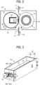
FIG. 2 is a diagram illustrating a configuration of a fixing device incorporated in the image forming apparatus ofFIG. 1 ; -
FIG. 3 is a perspective view of the fixing device ofFIG. 2 ; -
FIG. 4 is a perspective view of a fixing sub-assembly unit of a fixing device; -
FIG. 5 is an exploded view of the fixing device ofFIG. 3 ; -
FIG. 6A is a schematic top view of a planar heater; -
FIG. 6B is a schematic side view of the planar heater ofFIG. 6A ; -
FIG. 7 is a perspective view of a connector attached to a holder holding a planar heater; -
FIG. 8 is an exploded view illustrating a connector, a holder, a flange, and a stay; -
FIG. 9 is a perspective view of a flange; -
FIG. 10 is a side view of the flange ofFIG. 9 to illustrate a cutout; -
FIG. 11A is a side view of a flange, a stay, a holder, and a planar heater that is correctly set in the holder, viewed in an axial direction; -
FIG. 11B is a side view of a flange, a stay, a holder, and a planar heater that is wrongly set in the holder and rides on one end of the holder, viewed in an axial direction; -
FIGS. 12A and 12B are diagrams illustrating action to attach a flange to a sub-assembly unit in which a planar heater is correctly assembled to a holder held by a stay; -
FIG. 12C is a diagram illustrating a flange having a taper that enhances workability; -
FIGS. 13A and 13B are diagrams illustrating action to attach a flange to a sub-assembly unit including a planar heater that rides on a holder and is assembled to the holder held by a stay; -
FIGS. 14A and 14B are diagrams illustrating action to attach a flange according to a comparative example including a bridging portion that forms a large gap between the planar heater and the bridging portion to a sub-assembly unit including a planar heater that rides on a holder and is assembled to the holder held by a stay; -
FIG. 15 is a schematic view of a part of a fixing device as viewed in an axial direction; -
FIG. 16 is a schematic view of a part of a fixing device according to a comparative example, as viewed in an axial direction; -
FIG. 17 is a side view of a flange according to a first modification, a holder holding a planar heater, and a connector coupled to the planar heater, as viewed in an axial direction; -
FIG. 18 is a side view of a flange as another embodiment ofFIG. 17 , a holder holding a planar heater, and a connector coupled to the planar heater, as viewed in an axial direction; -
FIGS. 19A to 19C are diagrams illustrating action to attach a flange according to a second modification to a sub-assembly unit including a planar heater that rides on a holder and is assembled to the holder held by a stay; -
FIG. 20 is a cross-sectional view of a flange as another embodiment ofFIGS. 19A to 19C ; -
FIGS. 21A and 21B are schematic diagrams of a configuration according to a third modification including a thermostat as a pusher pushing a planar heater; -
FIG. 22 is a side view of a flange according to a fourth modification, a stay, a holder, and a planar heater, as viewed in an axial direction; -
FIG. 23 is a side view of a flange according to a comparative example of the flange ofFIG. 22 ; -
FIGS. 24A and 24B are schematic diagrams of a configuration according to a fifth modification including a thermal equalizer; -
FIG. 25 is a schematic diagram illustrating a two-dimensional atomic crystal structure of graphene; -
FIG. 26 is a schematic diagram illustrating a three-dimensional atomic crystal structure of graphite; and -
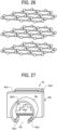
FIG. 27 is a perspective view of a flange according to a sixth modification. - The accompanying drawings are intended to depict embodiments of the present disclosure and should not be interpreted to limit the scope thereof. The accompanying drawings are not to be considered as drawn to scale unless explicitly noted. Also, identical or similar reference numerals designate identical or similar components throughout the several views.
- In describing embodiments illustrated in the drawings, specific terminology is employed for the sake of clarity. However, the disclosure of this specification is not intended to be limited to the specific terminology so selected and it is to be understood that each specific element includes all technical equivalents that have a similar function, operate in a similar manner, and achieve a similar result.
- Referring now to the drawings, embodiments of the present disclosure are described below. As used herein, the singular forms "a," "an," and "the" are intended to include the plural forms as well, unless the context clearly indicates otherwise.
- Embodiments of the present invention are described below in detail with reference to the drawings. Like reference signs are assigned to identical or equivalent components and a description of those components may be simplified or omitted.
- Initially with reference to
FIG. 1 , a configuration and operation of animage forming apparatus 1 according to an embodiment of the present invention is described below. - As illustrated in
FIG. 1 , theimage forming apparatus 1 according to the present embodiment is a tandem-type color printer. Theimage forming apparatus 1 includes abottle housing 101 in an upper portion of theimage forming apparatus 1. Thebottle housing 101 accommodates fourtoner bottles bottle housing 101 for replacement. - Under the
bottle housing 101, anintermediate transfer unit 85 is disposed. Facing anintermediate transfer belt 78 of theintermediate transfer unit 85,image forming devices - The
image forming devices photoconductor drums charger 75, a developingdevice 76, a cleaner 77, and a discharger. Image forming processes including a charging process, an exposure process, a developing process, a primary transfer process, and a cleaning process are performed on an outer circumferential surface of each of the photoconductor drums 5Y, 5M, 5C, and 5K, forming yellow, magenta, cyan, and black toner images on the photoconductor drums 5Y, 5M, 5C, and 5K, respectively. - A motor drives and rotates the photoconductor drums 5Y, 5M, 5C, and 5K clockwise in
FIG. 1 . Thechargers 75 uniformly charge the surfaces of the photoconductor drums 5Y, 5M, 5C, and 5K, respectively, which is referred to as the charging process. - After the charging process, the charged outer circumferential surface of each of the photoconductor drums 5Y, 5M, 5C, and 5K reaches an irradiation position at which an
exposure device 3 irradiates and scans the photoconductor drums 5Y, 5M, 5C, and 5K with laser beams L, irradiating and scanning the photoconductor drums 5Y, 5M, 5C, and 5K with the laser beams L forms electrostatic latent images according to yellow, magenta, cyan, and black image data in the exposure process. - After the exposure process, the irradiated and scanned outer circumferential surface of each of the photoconductor drums 5Y, 5M, 5C, and 5K reaches a developing position at which the developing
device 76 is disposed opposite each of the photoconductor drums 5Y, 5M, 5C, and 5K, and the developingdevice 76 develops the electrostatic latent image formed on therespective photoconductor drums - After the developing process, the yellow, magenta, cyan, and black toner images formed on the photoconductor drums 5Y, 5M, 5C, and 5K reach primary transfer nips formed between the
photoconductor drums intermediate transfer belt 78 by four primarytransfer bias rollers photoconductor drums intermediate transfer belt 78, respectively, and the yellow, magenta, cyan, and black toner images are primarily transferred onto theintermediate transfer belt 78 in a primary transfer process. After the primary transfer process, residual toner failed to be transferred onto theintermediate transfer belt 78 remains on the photoconductor drums 5Y, 5M, 5C, and 5K slightly. - After the primary transfer process, the residual toner on each of the photoconductor drums 5Y, 5M, 5C, and 5K reaches a cleaning position at which the cleaner 77 is disposed opposite each of the photoconductor drums 5Y, 5M, 5C, and 5K, and a cleaning blade of the cleaner 77 mechanically collects the residual toner from each of the photoconductor drums 5Y, 5M, 5C, and 5K in the cleaning process.
- Finally, the cleaned outer circumferential surface of each of the photoconductor drums 5Y, 5M, 5C, and 5K reaches a discharging position at which the discharger is disposed opposite each of the photoconductor drums 5Y, 5M, 5C, and 5K, and the discharger eliminates residual potential from each of the photoconductor drums 5Y, 5M, 5C, and 5K.
- Thus, a series of image forming processes performed on the photoconductor drums 5Y, 5M, 5C, and 5K is finished.
- The yellow, magenta, cyan, and black toner images formed on the photoconductor drums 5Y, 5M, 5C, and 5K in the developing process are primarily transferred onto an outer circumferential surface of the
intermediate transfer belt 78 such that the yellow, magenta, cyan, and black toner images are superimposed on a same position on theintermediate transfer belt 78. Thus, a color toner image is formed on theintermediate transfer belt 78. - The
intermediate transfer unit 85 includes theintermediate transfer belt 78, the four primarytransfer bias rollers transfer backup roller 82, a cleaningbackup roller 83, atension roller 84, and an intermediatetransfer belt cleaner 80. Theintermediate transfer belt 78 is stretched taut across and supported by the three rollers, that is, the secondarytransfer backup roller 82, the cleaningbackup roller 83, and thetension roller 84. One of the three rollers, that is, the secondarytransfer backup roller 82, drives and rotates theintermediate transfer belt 78 in a rotation direction indicated by an arrow inFIG. 1 . - The four primary
transfer bias rollers intermediate transfer belt 78 together with the fourphotoconductor drums intermediate transfer belt 78 and the photoconductor drums 5Y, 5M, 5C, and 5K. Each of the primarytransfer bias rollers - The
intermediate transfer belt 78 is moved in the direction indicated by the arrow inFIG. 1 and sequentially passes through the primary transfer nips formed by the primarytransfer bias rollers intermediate transfer belt 78, thereby forming the color toner image. - Subsequently, the
intermediate transfer belt 78 bearing the color toner image reaches a position opposite asecondary transfer roller 89. At the position, the secondarytransfer backup roller 82 and thesecondary transfer roller 89 press against each other via theintermediate transfer belt 78, and the contact portion therebetween is referred to as a secondary transfer nip below. The four color toner image formed on theintermediate transfer belt 78 is transferred onto the sheet P conveyed to the position of the secondary transfer nip. At this time, untransferred toner that is not transferred onto the sheet P remains on the surface of theintermediate transfer belt 78. - The
intermediate transfer belt 78 reaches a position opposite the intermediatetransfer belt cleaner 80. At the position, the intermediatetransfer belt cleaner 80 collects the untransferred toner from theintermediate transfer belt 78. - Thus, a series of transfer processes performed on the
intermediate transfer belt 78 is completed. - The sheet P conveyed through the secondary transfer nip is conveyed from a
sheet feeder 12 disposed in a lower portion of the body of theimage forming apparatus 1 through afeed roller 97, a registration roller pair 98 (e.g., a timing roller pair). Specifically, thesheet feeder 12 contains a stack of multiple sheets P such as sheets of paper stacked on top of one another. As thefeed roller 97 rotates counterclockwise inFIG. 1 , thefeed roller 97 feeds an uppermost sheet P in thesheet feeder 12 to a roller nip between theregistration roller pair 98. - The
registration roller pair 98 stops rotating temporarily, stopping the sheet P with a leading edge of the sheet P nipped in the roller nip between theregistration roller pair 98. Subsequently, theregistration roller pair 98 rotates to convey the sheet P to the secondary transfer nip, timed to coincide with the arrival of the color toner image on theintermediate transfer belt 78. Thus, the desired color toner image is transferred onto the sheet P. - After the
secondary transfer roller 89 transfers the color toner image onto the sheet P at the secondary transfer nip, the sheet P is conveyed to a fixingdevice 20. In the fixingdevice 20, a fixingbelt 22 and apressure roller 31 apply heat and pressure to the sheet P to fix the transferred color toner image on the sheet P, which is referred to as a fixing process. - After the fixing process, the sheet P bearing the fixed toner image is conveyed through a roller nip formed by an
output roller pair 99 and ejected by theoutput roller pair 99 onto an outside of theimage forming apparatus 1. The sheets P ejected by theoutput roller pair 99 are sequentially stacked as output images on astack section 100. - Thus, a series of image forming processes performed by the
image forming apparatus 1 is completed. - Referring to
FIGS. 2 to 8 , the following describes a configuration and operation of the fixingdevice 20 as the heating device incorporated in theimage forming apparatus 1. - With reference to
FIGS. 2 to 5 , the fixingdevice 20 as the heating device includes a fixingbelt 22 as a belt, astay 30 as a reinforcement, aplanar heater 24 as a heater, aholder 23, a pair offlanges 42, apressure roller 31 as a pressure rotator, and atemperature sensor 40 as a temperature detector. The fixingdevice 20 can be attached to and detached from the body of theimage forming apparatus 1 by rotating an opening and closing cover 110 (seeFIG. 1 ) on ahinge 110a in the body of theimage forming apparatus 1. In the present embodiment, the fixingbelt 22, theplanar heater 24, theholder 23, thestay 30, and the pair offlanges 42 are assembled to form a fixingsub-assembly unit 21 as a single unit (seeFIG. 4 ). - The fixing
belt 22 as a fixing rotator is an endless belt that is in contact with an outer circumferential surface of thepressure roller 31 and driven to rotate by rotation of thepressure roller 31. The fixingbelt 22 is a thin, flexible endless belt driven to rotate counterclockwise inFIG. 2 , that is, in a rotation direction indicated by an arrow inFIG. 2 . The fixingbelt 22 includes a base layer having an inner circumferential surface (i.e., a sliding contact surface of the fixingbelt 22 sliding over the planar heater 24), an elastic layer coating the base layer, and a release layer coating the elastic layer, which define a total thickness of the fixingbelt 22 not greater than 1 mm. - The base layer of the fixing
belt 22 has a thickness in a range of from 30 µm to 50 µm and is made of metal, such as nickel or stainless steel, or resin such as polyimide. - The elastic layer of the fixing
belt 22 has a thickness of 100 µm to 300 µm and is made of rubber such as silicone rubber, foamable silicone rubber, or fluoro rubber. The elastic layer absorbs slight surface asperities of the fixingbelt 22 at a fixing nip formed between the fixingbelt 22 and thepressure roller 31, facilitating even heat conduction from the fixingbelt 22 to the color toner image T on the sheet P and thereby preventing formation of an orange peel image on the sheet P. - The release layer of the fixing
belt 22 has a thickness in a range of from 5 µm to 50 µm and is made of material such as tetrafluoroethylene-perfluoroalkyl vinyl ether copolymer (PFA), polytetrafluoroethylene (PTFE), polyimide, polyether imide, and polyether sulfone (PES). The release layer facilitates separation or peeling-off of toner of the color toner image T on the sheet P from the fixingbelt 22. - Inside a loop of the fixing
belt 22, theplanar heater 24, theholder 23 and thestay 30 are disposed - The
planar heater 24 is disposed so as to extend in a width direction that is a direction perpendicular to the surface of the paper on whichFIG. 2 is drawn. Theplanar heater 24 contacts the inner circumferential surface of the fixingbelt 22. Theplanar heater 24 is pressed against thepressure roller 31 via the fixingbelt 22 to form the fixing nip through which the sheet P is conveyed. Theplanar heater 24 is disposed inside the loop formed by the fixingbelt 22 such that the inner circumferential surface of the fixingbelt 22 slides over theplanar heater 24. Pressing theplanar heater 24 against thepressure roller 31 via the fixingbelt 22 forms the fixing nip through which the sheet P is conveyed. As described above, theplanar heater 24 functions as a nip formation pad that is a member forming the fixing nip. Theplanar heater 24 may include a surface layer or a sheet made of low friction material such as PTFE on the surface of theplanar heater 24 to reduce sliding friction between the fixingbelt 22 and theplanar heater 24. - In addition, the
planar heater 24 includes resistor patterns 26 (seeFIGS. 6A and 6B ) formed on a portion that is in sliding contact with the inner circumferential surface of the fixingbelt 22. A power supply supplies electric power to theresistor patterns 26 that are resistive heat generators, and each of theresistor patterns 26 generates heat according to the resistance of theresistor pattern 26 to heat the fixingbelt 22. As described above, theplanar heater 24 also functions as a heating unit (heating body) that heats the fixingbelt 22. - In the present embodiment, the
holder 23 holds theplanar heater 24. Theholder 23 has arecess 23a (seeFIGS. 12A, 12B ,13A, and 13B ). Theplanar heater 24 is fitted into therecess 23a to hold theplanar heater 24 in the width direction. - The
stay 30 holds theholder 23 holding theplanar heater 24. The fixingdevice 20 includes ahousing 43 including afirst frame 43a. Thefirst frame 43a holds both ends of thestay 30 holding theplanar heater 24 and theholder 23 in the width direction (seeFIG. 3 ) via theflanges 42. - As described above, the planar heater 24 (the resistor pattern 26) disposed inside the loop of the fixing
belt 22 directly heats the fixingbelt 22. The outer circumferential surface of the fixingbelt 22 heated by theplanar heater 24 heats the toner image T on the sheet P. The output of theplanar heater 24 is controlled based on the temperature of the outer circumferential surface of the fixingbelt 22 detected by thetemperature sensor 40. Thetemperature sensor 40 is a thermopile or a thermistor disposed opposite the outer circumferential surface of the fixingbelt 22. Theplanar heater 24 controlled as described above heats the fixingbelt 22 to a desired fixing temperature. - Although the fixing
device 20 in the present embodiment includes thetemperature sensor 40 that directly detects the fixing temperature of the fixingbelt 22, the fixingdevice 20 may include a temperature sensor such as a thermostat or a thermistor that detects the surface temperature of theplanar heater 24 to indirectly detect the fixing temperature of the fixing belt 22 (seeFIG. 21 ). In such a case, the temperature sensor in contact with theplanar heater 24 can also function as a safety device for preventing an excessive temperature rise in theplanar heater 24. - Referring to
FIG. 5 andFIG. 9 , the pair offlanges 42 as guides guide both ends of the inner circumferential surface of the fixingbelt 22 in the width direction of the fixingbelt 22 such that the fixingbelt 22 maintains a substantially cylindrical posture. - Specifically, the two
flanges 42 are made of a heat-resistant resin material and are fitted into both sides of thehousing 43 in the width direction of thehousing 43 of the fixingdevice 20 so that theflanges 42 can slide and move along both sides. Each of theflanges 42 includes atubular portion 42a and a restrictingmember 42b as a stopper. Thetubular portion 42a holds the fixingbelt 22 to maintain the substantially cylindrical posture thereof. The restrictingmember 42b restricts the motion or skew of the fixingbelt 22 in the width direction thereof. - In addition, as illustrated in
FIG. 3 , the fixingdevice 20 according to the present embodiment includes compression springs 52 as biasing members. Biasing forces of the compression springs 52 press theflanges 42, respectively. As a result, the fixingbelt 22, theplanar heater 24, theholder 23, and thestay 30 are pressed against thepressure roller 31 by the biasing forces. - The
flanges 42 support both end portions of the fixingbelt 22 in the width direction of the fixingbelt 22 except for both end portions corresponding to the fixing nip so that theplanar heater 24 can form the fixing nip. - As described above, the inner circumferential surface of the fixing
belt 22 is loosely contacted only by theflanges 42 at respective ends of the fixingbelt 22 in the width direction thereof and theplanar heater 24. No other component, such as a belt guide, contacts the inner circumferential surface of the fixingbelt 22 to guide the fixingbelt 22 as it rotates. - The fixing
device 20 according to the present embodiment includes thestay 30 that is disposed inside the loop of the fixingbelt 22 so as to be in contact with thepressure roller 31 via theholder 23, theplanar heater 24, and the fixingbelt 22. Thestay 30 reinforces theholder 23 and theplanar heater 24 forming the fixing nip to enhance the mechanical strength of theholder 23 and theplanar heater 24. Thehousing 43 holds thestay 30 via theflanges 42. (SeeFIGS. 2 ,5 ,8 ,12A, and 12B ) - The
stay 30 receiving the pressure from thepressure roller 31 via theholder 23, theplanar heater 24, and the fixingbelt 22 prevents a disadvantage that the pressure from thepressure roller 31 largely deforms the planar heater 24 (and the holder 23) at the fixing nip. Preferably, thestay 30 is made of metal having an increased mechanical strength, such as stainless steel or iron, to achieve the above-described function. - The
holder 23 may be made of resin or metal. Preferably, theholder 23 is made of resin that has rigidity to prevent theholder 23 from bending even if theholder 23 receives pressure from thepressure roller 31, and the resin preferably has heat resistance and thermal insulation. The resin may be liquid crystal polymer (LCP), polyamide imide (PAI), polyether sulfone (PES), polyphenylene sulfide (PPS), polyether nitrile (PEN), and polyether ether ketone (PEEK). In the present embodiment, liquid crystal polymer (LCP) is used as the material of theholder 23. - Referring to
FIG. 2 , thepressure roller 31 as the pressure rotator includes a cored bar 32 (serving as an axial portion) and anelastic layer 33 coating the coredbar 32. Thepressure roller 31 is driven and rotated clockwise inFIG. 2 by a drive motor. - The cored
bar 32 of thepressure roller 31 has a hollow structure made of metal. Theelastic layer 33 of thepressure roller 31 is made of material such as foamable silicone rubber, silicone rubber, or fluoro rubber. A thin release layer made of PFA or PTFE may be provided on the surface of theelastic layer 33. Thepressure roller 31 is pressed against the fixingbelt 22 to form a desired nip between the fixingbelt 22 and thepressure roller 31. As illustrated inFIG. 3 , agear 45 is attached to thepressure roller 31 and engages a driving gear of the drive motor so that thepressure roller 31 is driven and rotated clockwise inFIG. 2 , that is, a direction indicated by the arrow inFIG. 2 . Both ends of thepressure roller 31 in the width direction of thepressure roller 31 are rotatably supported by thehousing 43 of the fixingdevice 20 through bearings, respectively. - Referring to
FIGS. 3 to 5 , thehousing 43 as the frame of the fixingdevice 20 in the present embodiment includes two frames that are thefirst frame 43a and asecond frame 43b. Thefirst frame 43a and thesecond frame 43b can be separated from each other. - Specifically, the
first frame 43a functions as a main portion of thehousing 43 and has a substantially U-shaped cross section. Thefirst frame 43a hasguides 43x that fit into grooves 42b1 formed in theflanges 42 of the fixingsub-assembly unit 21 and bearing portions to receive a shaft of thepressure roller 31. Thepressure roller 31 and the fixingsub-assembly unit 21 are assembled to thefirst frame 43a. Thesecond frame 43b is a lid-shaped frame that is installed (joined) to thefirst frame 43a so as to cover the fixingsub-assembly unit 21. When thesecond frame 43b is set on thefirst frame 43a, compression springs 52 (seeFIG. 5 ) as biasing members are interposed between theflanges 42 of the fixingsub-assembly unit 21 and thesecond frame 43b. The compression springs 52 function as biasing members that press the pair offlanges 42 against thepressure roller 31 as the pressure rotator. - Referring to
FIGS. 6A and 6B , theplanar heater 24 in the present embodiment includes abase 25, the resistor patterns 26 (the resistive heat generators), conductor patterns 27 (relay portions),power supply electrodes 28 as electrodes. - The
base 25 has a front surface facing the inner circumferential surface of the fixingbelt 22 in the fixing nip. At least the front surface of thebase 25 is made of an insulative material. In the present embodiment, thebase 25 is entirely made of the insulative material (aluminum nitride (AlN) in the present embodiment). - The
resistor patterns 26 are formed on the front surface of thebase 25. Similarly, theconductor patterns 27 are also formed on the front surface of thebase 25. A current flows through the resistor pattern 26 (that is, energizing the resistor pattern 26), the resistance of theresistor pattern 26 generates heat, and theresistor pattern 26 functions as the resistive heat generator. Theresistor pattern 26 is formed by applying and screen-printing a paste prepared to have a desired resistance value to the surface of thebase 25 and baking the paste after screen-printing. - Each of the
conductor patterns 27 electrically couples between theresistor patterns 26 or between theresistor pattern 26 and thepower supply electrode 28 to function as the relay portion that flows the current input from thepower supply electrode 28 to theresistor pattern 26. Theconductor pattern 27 is formed by applying and screen-printing a paste having high conductivity to the surface of thebase 25 and baking the paste after screen-printing. - The
power supply electrode 28 is electrically coupled to theconductor pattern 27 and is formed to couple to an external terminal that is a contact 29a1 of a terminal 29a of a connector 29 (seeFIG. 7 ). Accordingly, even when the surface layer having electrical insulating properties and low friction properties is formed on the entire surface of theplanar heater 24, a part of the surface layer over thepower supply electrode 28 is removed to expose thepower supply electrode 28 and supply power to thepower supply electrode 28. - The
power supply electrode 28 is made of a silver-based material such as silver (Ag) or silver palladium (AgPd) in order to reduce heat generation due to energization. In the present embodiment, thepower supply electrode 28 is formed by screen-printing the material on the surface of thebase 25 and baking the material after screen-printing. - Referring to
FIGS. 7 ,8 , and12B , theconnector 29 is mounted so as to sandwich an end of theholder 23 holding theplanar heater 24 in the width direction. After the fixingsub-assembly unit 21 as illustrated inFIG. 3 is installed in thehousing 43, theconnector 29 is set on one end of the fixingsub-assembly unit 21 as illustrated inFIG. 12B . - The
connector 29 has a U-shaped cross sectional shape in a cross section orthogonal to the width direction. Theconnector 29 includes theterminals 29a disposed inside the U-shaped cross sectional shape. When theconnector 29 is attached to theholder 23 so as to sandwich theholder 23, the contacts 29a1 of theterminals 29a are electrically connected to thepower supply electrodes 28 of theplanar heater 24. The above-described configuration enables the power supply in the body of theimage forming apparatus 1 to supply the electric power toresistor patterns 26 of theplanar heater 24 viaharnesses 90, theterminals 29a, and thepower supply electrodes 28. - In the present embodiment, the
connector 29 and theharnesses 90 are held by clamps on the outer surface of the housing 43 (thesecond frame 43b) of the fixingdevice 20. Theimage forming apparatus 1 includes a body side connector coupled to the power supply. Theharnesses 90 are coupled to a second connector on the fixingdevice 20. The second connector is connected to and disconnected from the body side connector in conjunction with an operation of attaching and detaching the fixingdevice 20 to and from the body of theimage forming apparatus 1. - A description is provided of a regular fixing process to fix the toner image T on the sheet P, which is performed by the fixing
device 20 having the construction described above. - Turning on a power switch on the body of the
image forming apparatus 1 supplies power to theplanar heater 24, and the motor starts driving and rotating thepressure roller 31 clockwise inFIG. 2 , that is, in a direction indicated by an arrow inFIG. 2 . Due to friction between thepressure roller 31 and the fixingbelt 22, rotating thepressure roller 31 drives and rotates the fixingbelt 22 counterclockwise inFIG. 2 . - Thereafter, the sheet P is fed from the
sheet feeder 12, and the color toner image is transferred onto the sheet P at the position of thesecondary transfer roller 89. As a result, the sheet P bears an unfixed color image. As illustrated inFIG. 2 , the sheet P bearing the unfixed toner image T is conveyed in a direction indicated by an arrow Y10 while the sheet P is guided by a guide plate and enters the fixing nip formed between the fixingbelt 22 and thepressure roller 31 pressed against the fixingbelt 22. - The
stay 30 reinforces the planar heater 24 (and the holder 23). The toner image T is fixed on a surface of the sheet P under heat from the fixingbelt 22 heated by theplanar heater 24 and pressure exerted from thepressure roller 31 and the planar heater 24 (and the holder 23). Thereafter, the sheet P is ejected from the fixing nip and conveyed in a direction indicated by an arrow Y11 inFIG. 2 . - The following describes a configuration and operation of the fixing
device 20 as the heating device in detail. - As described above with reference to
FIGS. 2 to 8 , the fixingdevice 20 as the heating device includes theplanar heater 24, the fixingbelt 22, thepressure roller 31, theholder 23, thestay 30, the pair offlanges 42, thehousing 43, the compression springs 52. - The
planar heater 24 has a substantially rectangular parallelepiped shape extending in the width direction that is the horizontal direction inFIG. 12 and the direction perpendicular to the paper surface on whichFIGS. 2 ,11A, and 11B are drawn. Theplanar heater 24 heats the fixingbelt 22, and the fixingbelt 22 heats the toner image to fix the toner image on the face of the sheet P. - The
pressure roller 31 as the pressure rotator is pressed against theplanar heater 24 via the fixingbelt 22 to form the fixing nip in which the sheet P is conveyed. Theholder 23 holds the entirety of theplanar heater 24 extending in the width direction. Theholder 23 in the present embodiment is made of resin. Thestay 30 holds theholder 23 and also functions as a reinforcement to reinforce the mechanical strength of theholder 23. Thestay 30 in the present embodiment is made of metal. Thestay 30 has a U-shaped cross section. Thestay 30 has projections at both ends in the width direction, and the projections disposed at the end of thestay 30 are fitted into theflange 42 as illustrated inFIG. 8 . - The pair of
flanges 42 is configured to hold both ends of thestay 30 in the width direction and to hold both ends of the fixingbelt 22 in the width direction. Thehousing 43 holds the pair offlanges 42 so as to be movable in the horizontal direction inFIGS. 2 and15 . Moving theflange 42 in the horizontal direction changes the distance between theflange 42 and thepressure roller 31. The compression springs 52 function as biasing members that bias the pair offlanges 42 in a direction approaching thepressure roller 31 as the pressure rotator. - Referring to
FIGS. 9 and10 , theflange 42 in the present embodiment includes thetubular portion 42a and the restrictingmember 42b that have acutout 42c. The restrictingmember 42b hasgrooves 42btubular portion 42a of theflange 42 faces the inner circumferential surface of the fixingbelt 22 to maintain the substantially tubular posture of the fixingbelt 22. Since thetubular portion 42a has thecutout 42c, the sectional shape of the outer peripheral surface of thetubular portion 42a is not a perfect circle and is an arc. - The restricting
member 42b of theflange 42 contacts an edge of the fixingbelt 22 to restrict the movement of the fixingbelt 22 in the width direction. The restrictingmember 42b has a wall that is adjacent to thetubular portion 42a and sufficiently larger than thetubular portion 42a so that the wall contacts the edge of the fixingbelt 22. Thecutout 42c of theflange 42 extends over thetubular portion 42a and the restrictingmember 42b and is formed at a portion corresponding to the fixing nip. Thecutout 42c functions as a clearance portion so that the contact between the fixingbelt 22 and thepressure roller 31 favorably forms the fixing nip. - Referring to
FIGS. 9 and10 , the bridging portion 42b2 bridges and closes thecutout 42c at a position adjacent to the outer face of the restrictingmember 42b in the width direction (i.e., the right end of the restrictingmember 42b inFIG. 10 , a face opposite to the inner face of the restrictingmember 42b adjacent to thetubular portion 42a, the face away from the fixing belt 22). In other words, the inner portion of the restrictingmember 42b in the width direction has a substantially U-shaped cross section formed by thecutout 42c, and the outer portion of the restrictingmember 42b in the width direction has a substantially square cross section formed by the bridging portion 42b2. In the width direction, the position of the bridging portion 42b2 is outside the fixing nip between the fixingbelt 22 and thepressure roller 31 and outside thetubular portion 42a. - The
flange 42 including the bridging portion 42b2, which is formed as described above, is less likely to cause deformation due to resin-molding (deformation in which both tips of the U shape are closed, see theflange 142 inFIG. 16 ) than the flange not including the bridging portion 42b2. Further, theflange 42 including the bridging portion 42b2 has a larger mechanical strength than the flange not including the bridging portion 42b2. - When the
flange 42 is moved in the width direction relative to a sub-assembly in which theplanar heater 24, theholder 23, and thestay 30 are assembled as illustrated inFIG. 12A to assemble theflange 42 to the sub-assembly as illustrated inFIGS. 12A and 12B , disadvantage that aflange 142 that is partially deformed is assembled to the sub-assembly as illustrated inFIG. 16 is less likely to occur. As a result, the normal flange having no deformation is assembled to the sub-assembly as illustrated inFIG. 15 . - Accordingly, the
flange 42 including the bridging portion 42b2 can prevent the disadvantage that theplanar heater 24 is set to be deviated from the fixing nip, does not typically function, and causes a fixing failure as in the comparative example illustrated inFIG. 16 . In the present embodiment, theplanar heater 24 is correctly set to face the fixing nip as illustrated inFIG. 15 and correctly functions. - As illustrated in
FIG. 12C , theflange 42 may include a taper 42b2T having a taper angle of about 30° to 60° on a wall face downstream in a mounting direction (the left wall of the flange inFIG. 12C ). The taper 42b2T enhances the workability when theflange 42 in the present embodiment is relatively moved in the width direction to assemble theflange 42 to the sub-assembly of theholder 23, thestay 30, and theplanar heater 24 that is wrongly assembled to theholder 23. In particular, since theplanar heater 24 is relatively weak against impact, it is preferable that the taper 42b2T of theflange 42 is set to be larger than the thickness of theplanar heater 24. - As illustrated in
FIGS. 9 and10 , the restrictingmember 42b of theflange 42 has grooves 42b1 formed on portions adjacent to both ends of the bridging portion 42b2 (i.e., an upper portion and a lower portion of the restrictingmember 42b inFIG. 10 ). Theguides 43x of the housing 43 (seeFIGS. 3 and5 ) slide on the grooves 42b1 and fitted to thegrooves 42b - As described above with reference to
FIG. 5 , thecompression spring 52 is disposed between thesecond frame 43b and each of theflanges 42. The compression springs 52 press theflanges 42, and theflanges 42 move along theguides 43x (that slide on the grooves 42b1) in a pressing direction to press the fixingbelt 22 against thepressure roller 31. - Referring to
FIGS. 11A and12A , the fixingdevice 20 of the present embodiment is designed to have a gap M between the bridging portion 42b2 and theplanar heater 24 in a direction orthogonal to the width direction and a sheet conveyance direction that is smaller than a depth N of therecess 23a in theholder 23 into which theplanar heater 24 is fitted (M < N). The depth N may be referred to as a heater restricting height. The sheet conveyance direction is defined as the direction in which the sheet P is conveyed in the fixingdevice 20. - In the above-described configuration, the bridging portion 42b2 of the
flange 42 interferes with the end face of theplanar heater 24 that is not correctly set on theholder 23 and is separated from the bottom of therecess 23a (in other words, rides on the end of the holder 23) as illustrated inFIGS. 11B and13B . As a result, the worker who assembles theflange 42 to the sub-assembly including theplanar heater 24 and theholder 23 can notice that theplanar heater 24 is not correctly set on theholder 23. The worker correctly resets theplanar heater 24 on theholder 23 and correctly assembles theflange 42 to the sub-assembly as illustrated inFIGS. 12A and 12B . - In the present specification, the "gap between the bridging portion and the planar heater" is defined as a gap measured under a condition that the belt such as the fixing
belt 22 is pressed against the pressure rotator such as thepressure roller 31 to form a nip. In other words, the "gap between the bridging portion and the planar heater" is measured under the condition that the planar heater, the holder, and the stay are moved to be close to the flange. - In the present specification, "the depth (N) of the recess in the holder into which the planar heater is fitted" is defined as the deepest depth if the depth (N) varies depending on a position in the recess. However, the depth (N) is measured more preferably at a position facing the flange or at a position outside of the flange than at the position of the center of the holder in the width direction.
- The above-described structure can prevent the disadvantage that the
flange 42 is assembled to the sub-assembly in which theplanar heater 24 is not correctly set on theholder 23 when theflange 42 is relatively moved to the sub-assembly in which theplanar heater 24, theholder 23, and thestay 30 are assembled to assemble theflange 42 to the sub-assembly because the gap M between the bridging portion 42b2 and theplanar heater 24 is smaller than the depth N of therecess 23a in theholder 23. As a result, the above-described structure also prevents the disadvantage that theplanar heater 24 or theholder 23 is damaged by one end of theplanar heater 24 that rides on the end of the holder and contacts thepressure roller 31 or theholder 23 with a strong force when the nip is formed. - The bridging portion 42b2 functions to prevent the
planar heater 24 from falling off from the fixingsub-assembly unit 21 even when some forces are applied to the fixingsub-assembly unit 21 by releasing (or reducing) the pressure of thepressure roller 31 with respect to the fixingbelt 22 after the fixingdevice 20 is incorporated in the image forming apparatus. -
FIGS. 14A and 14B are diagrams illustrating the action to attach a flange according to a comparative example to the fixing sub-assembly unit. In the comparative example, the gap M between the bridging portion 42b2 and theplanar heater 24 is larger than the depth N of therecess 23a in the holder 23 (M > N). As a result, when theflange 42 is assembled to the fixing sub-assembly unit in which theplanar heater 24 is not correctly set on the holder and rides on the holder, the bridging portion 42b2 of theflange 42 does not interfere with the end face of theplanar heater 24 as illustrated inFIG. 14B . Accordingly, the worker assembles the flange to the fixing sub-assembly unit without noticing that theplanar heater 24 is not correctly set on theholder 23. - In such a case, as illustrated in
FIG. 14 b , theconnector 29 cannot be attached so as to sandwich theplanar heater 24 and theholder 23. Theplanar heater 24, theholder 23, and theconnector 29 may collide with each other and be damaged. - As described above with reference to
FIG. 7 , theconnector 29 includes theterminals 29a contacting thepower supply electrodes 28 as the electrodes of theplanar heater 24. Theconnector 29 is mounted on theplanar heater 24 and theholder 23 in a predetermined mounting direction that is the direction indicated by the arrow inFIG. 7 and the direction orthogonal to the width direction so as to sandwich theplanar heater 24 and theholder 23. - The
planar heater 24 has a substantially rectangular cross section when viewed in the mounting direction that is the direction indicated by the arrow inFIG. 9 and protrudes from theholder 23 by a predetermined length W (= the thickness of the planar heater 24 - the depth N of therecess 23a). The above-described configuration is less likely to cause the disadvantage that theplanar heater 24 is caught on the inner face of theconnector 29 on which theterminals 29a are disposed and damaged when theconnector 29 is mounted on theplanar heater 24 and theholder 23. - Referring to
FIGS. 11A and 11B , theflange 42 is designed to be longer than theholder 23 in the sheet conveyance direction of the sheet P that is the vertical direction inFIGS. 11A and 11B . In a pressing direction in which thepressure roller 31 as the pressure rotator presses against the fixing belt and the planar heater (that is the horizontal direction inFIGS. 11A and 11B ), the thickness of theflange 42 is thicker than the thickness of theholder 23. The above-described configuration enables theflanges 42 to stably hold theholder 23 holding theplanar heater 24 via thestay 30. - As described above with reference to
FIG. 4 , the fixingdevice 20 according to the present embodiment includes the fixingsub-assembly unit 21 in which the fixingbelt 22, theplanar heater 24, theholder 23, thestay 30, and the pair offlanges 42 are unitized (sub-assembled) to enhance the entire assembly workability. The above-described structure effectively exhibits the effect of providing the bridging portion 42b2 in theflange 42 and the effect of configuring the gap M between the bridging portion 42b2 and theplanar heater 24 to be smaller than the depth N of therecess 23a in theholder 23 as described above at the time of assembling the fixingsub-assembly unit 21. - The following describes a first modification of the present embodiment.
- Similar to the fixing device illustrated in
FIGS. 12A and 12B , the fixingdevice 20 according to the first modification includes theconnector 29 disposed in the vicinity of theflange 42. - As illustrated in
FIG. 17 , the bridging portion 42b2 of theflange 42 in the fixingdevice 20 according to the first modification hasprojections 42x to restrict the movement of theplanar heater 24 in the horizontal direction inFIG. 17 that is a direction orthogonal to the mounting direction of theconnector 29 that is the direction indicated by the white arrow inFIG. 17 . Specifically, theprojection 42x is a boss having a hemispherical tip and is formed so as to project from an inner face of the bridging portion 42b2, the inner face facing theplanar heater 24, toward theplanar heater 24. However, theprojection 42x in the present embodiment does not contact theplanar heater 24. - The
projections 42x disposed as described above prevent the heater from separating from the heater holder by a certain amount or more. - In the mounting direction indicated by the white arrow in
FIG. 17 , theprojections 42x are disposed at positions different from contacting positions at which the contacts 29a1 of theterminals 29a of theconnector 29 are in contact with thepower supply electrodes 28. Attaching theflange 42 to theplanar heater 24 as illustrated inFIGS. 12A and 12B is likely to cause theprojection 42x to come into contact with thepower supply electrode 28 and damage thepower supply electrode 28. The above-described structure prevents the disadvantage caused by the damage of thepower supply electrode 28 of theplanar heater 24. - In the present embodiment, two
projections 42x are formed so as to sandwich a portion indicated by an alternate long and short dash line inFIG. 17 at which theterminals 29a are in contact with thepower supply electrodes 28 in the mounting direction indicated by the white arrow. Specifically, twoprojections 42x are disposed so as to sandwich the range X in which theterminals 29a are disposed. In other word, the contacting positions of theterminals 29a contacting theelectrodes 28 in the mounting direction are between the twoprojections 42x in the mounting direction. - In contrast, as illustrated in
FIG. 18 , the bridging portion 42b2 may have oneprojection 42x formed downstream from the range X in the mounting direction indicated by the white arrow. In other words, the oneprojection 42x may be downstream from the contact positions of theterminals 29a contacting theelectrodes 28 in the mounting direction. - The
holder 23 in the first modification may have notches 23a1 (clearance portions) corresponding to theprojections 42x in a wall of theholder 23 at a widthwise end of theholder 23 to avoid interference between theprojections 42x and theholder 23 caused by attaching theflange 42 to theholder 23. - The following describes a second modification of the present embodiment.
- As illustrated in
FIGS. 19A to 19C , the fixingdevice 20 in the second modification includes aflat spring 42z as an elastic body disposed on theflange 42. - As illustrated in
FIGS. 19A to 19C , theflat spring 42z is disposed on the bridging portion 42b2 and functions as the elastic body pressing theplanar heater 24 to fit into therecess 23a of theholder 23 when theflange 42 is relatively moved and attached to theholder 23 holding theplanar heater 24. Specifically, theflat spring 42z is formed so as to apply a force (an elastic force) in the direction indicated by an arrow inFIG. 19B to theplanar heater 24 when theflat spring 42z comes into contact with theplanar heater 24 in the process of attaching theflange 42 to theholder 23. - As a result, the
flat spring 42z pushes theplanar heater 24 riding on the holder 23 (in other words, theplanar heater 24 floating from the holder 23) into therecess 23a in the process of attaching theflange 42 to theholder 23 as illustrated inFIGS. 19A to 19C . Then theplanar heater 24 is correctly set to theholder 23. - In the mounting direction of the
connector 29, theflat spring 42z in the second modification is preferably disposed at a position different from the contacting positions at which the contacts 29a1 of theterminals 29a of theconnector 29 are in contact with thepower supply electrodes 28. Attaching theflange 42 to theholder 23 holding theplanar heater 24 as illustrated inFIGS. 19A to 19C is likely to cause theflat spring 42z to come into contact with thepower supply electrode 28 and damage thepower supply electrode 28. The above-described structure prevents the disadvantage caused by the damage of thepower supply electrode 28 of theplanar heater 24. - As illustrated in
FIG. 20 , an elastic portion 42b20 functioning as an elastic body in the same manner as theflat spring 42z inFIG. 19 may be integrally formed on the bridging portion 42b2 of theflange 42. For example, the elastic portion 42b20 may be a resin spring integrally molded with theflange 42. The elastic portion 42b20 may be made of rubber and attached to theflange 42. - The following describes a third modification.
- As illustrated in
FIG. 21A , the fixingdevice 20 according to the third modification includes thermostats 49 (or thermistors) arranged at intervals in the width direction to detect surface temperatures of theplanar heater 24. - The
thermostats 49 detect the surface temperatures of theplanar heater 24 to indirectly detect the fixing temperature of the fixingbelt 22 and control the fixing temperature, in addition to function as a safety device for preventing an excessive temperature rise in theplanar heater 24. Thethermostats 49 also function as pushers to push theplanar heater 24 to thepressure roller 31 as the pressure rotator. Specifically, thethermostat 49 is configured to bias and contact the upper face of theplanar heater 24 inFIG. 21 , that is, the face opposite to another face forming the nip, by a predetermined contact pressure. - Pushing the
planar heater 24 toward thepressure roller 31 as described above favorably forms the nip. - As illustrated in
FIG. 21B , the fixingdevice 20 according to the third modification may include onethermostat 49 on one end of theplanar heater 24 in the width direction. In this case, theconnector 29 is preferably disposed at one end of theholder 23 closer to thethermostat 49 than the other end of the holder 23 (that is, the right side portion of theholder 23 inFIG. 21B ). In the above-described configuration, thethermostat 49 functioning as the pusher and the bridging portion 42b2 of theflange 42 generates a force pushing theplanar heater 24 to therecess 23a of theholder 23, which enhances the fitting performance of theconnector 29 mounted so as to sandwich theplanar heater 24 and theholder 23. - The
flange 42 may have the taper formed on the downstream side wall of theflange 42 in the mounting direction of theflange 42 to enhance the mounting performance of theflange 42. In the fixing device including thethermostat 49 on one end of theholder 23 as illustrated inFIG. 21B , theflange 42 that is set on one end of theholder 23 closer to thethermostat 49 than the other end of theholder 23 preferably has the taper larger than a taper of theflange 42 set on the other end of theholder 23. This is because a force of thethermostat 49 functioning as the pusher pushes one end of theplanar heater 24 that is closer to thethermostat 49 than the other end of theplanar heater 24 and separates one end of theplanar heater 24 from theholder 23 farther than the other end of theplanar heater 24, which is likely to cause difficulty to attach theflange 42 to theholder 23. Instead of thethermostat 49, a thermistor may be used as the pusher. - The following describes a fourth modification.
- As illustrated in
FIG. 22 , theflange 42 in the fixingdevice 20 as the heating device according to the fourth modification has a pair of facingportions 42w that face the bridging portion 42b2 via both ends of theholder 23 in a short-side direction of the holder 23 (that are both ends of theholder 23 in the vertical direction inFIG. 22 ). - In other words, in the cross section of the
flange 42 according to the fourth modification that is set to theholder 23 holding theplanar heater 24, in the cross section taken along the direction orthogonal to the width direction, both ends of theholder 23 in the short-side direction of theholder 23 that is the vertical direction inFIG. 22 are sandwiched between the bridging portion 42b2 and the facingportions 42w with a clearance therebetween. The pair of facing portions 43w are formed such that a sectional shape of theflange 42 having a space to set theholder 23 is a substantially convex shape. - The pair of facing
portions 42w function as holder restricting portions that restrict the movement of theholder 23 in the short-side direction. In the flange having the pair of facingportions 42w, the bridging portion 42b2 of theflange 42 interferes with the end face of theplanar heater 24 that is not correctly set on theholder 23 and is separated from the bottom of therecess 23a. As a result, the worker who assembles theflange 42 to the sub-assembly including theplanar heater 24 and theholder 23 can notice that theplanar heater 24 is not correctly set on theholder 23. -
FIG. 23 is a side view of aflange 42 according to a comparative example of theflange 42 ofFIG. 22 . Theflange 42 inFIG. 23 has one facingportion 42w facing one end of theholder 23 in the short-side direction of theholder 23 and no facing portion facing the other end of theholder 23 in the short-side direction of theholder 23. In this case, when theplanar heater 24 is not correctly set and floats from theholder 23, theholder 23 can change the posture to be inclined and not be fixed, and theflange 42 can be assembled to theholder 23. As a result, the bridging portion 42b2 of theflange 42 does not interfere with the end face of theplanar heater 24, and the worker who assembles the flange to the fixing sub-assembly unit cannot notice that theplanar heater 24 is not correctly set on theholder 23. For this reason, it is useful to form the pair of facingportions 42w in theflange 42 as illustrated inFIG. 22 . - The clearance between the facing
portion 42w and theholder 23 is designed in consideration of thermal expansions of related members so that the facingportion 42w does not contact theholder 23 even when theplanar heater 24 generates heat (even when the fixingdevice 20 is in operation). In other words, the clearance between the facingportion 42w and theholder 23 is designed so that each of the pair of facingportions 42w is separated from theholder 23 during heat generation of the planar heater. Designing the clearance as described above can prevent the disadvantage that the facingportion 42w and theholder 23 are deformed by contacting each other during the operation of the fixing device 20 (during the fixing process). - The following describes a fifth modification.
- As illustrated in
FIG. 24A , the fixingdevice 20 as the heating device according to the fifth modification includes athermal equalizer 60, and theholder 23 holds theplanar heater 24 via thethermal equalizer 60. - The
thermal equalizer 60 is a plate made of a high thermal conductive material such as aluminum, copper, silver, graphene, or graphite and is fitted to therecess 23a of theholder 23 together with theplanar heater 24. Thethermal equalizer 60 is formed so as to be in contact with substantially the entire surface of theplanar heater 24. Thethermal equalizer 60 disposed as described above reduces temperature unevenness (heating unevenness) in theplanar heater 24 itself and the fixingbelt 22 heated by theplanar heater 24. - In order to further enhance the effect of reducing such temperature unevenness, the fixing
device 20 may include secondthermal equalizers 61 made of the high thermal conductive material that is the same material of thethermal equalizer 60 in addition to thethermal equalizer 60 disposed in therecess 23a and interposed between theholder 23 and theplanar heater 24 as illustrated inFIG. 24B . The secondthermal equalizers 61 are interposed between thethermal equalizer 60 and theholder 23. When theplanar heater 24 includes theresistor patterns 26 such as the resistive heat generators arranged in the width direction, each of the secondthermal equalizer 61 is arranged so as to cover the ends of theadjacent resistor patterns 26 and the gap between theadjacent resistor patterns 26 as illustrated inFIG. 24B . - Graphene is a flaky powder. Graphene has a planar hexagonal lattice structure of carbon atoms, as illustrated in
FIG. 25 . The graphene sheet is typically a single layer. The graphene sheet may contain impurities in a single layer of carbon or may have a fullerene structure. The fullerene structures are generally recognized as compounds including an even number of carbon atoms, which form a cage-like fused ring polycyclic system with five and six membered rings, including, for example, C60, C70, and C80 fullerenes or other closed cage structures having three-coordinate carbon atoms. Graphene sheets are artificially made by, for example, a chemical vapor deposition (CVD) method. The graphene sheet is commercially available. The size and thickness of the graphene sheet or the number of layers of the graphite sheet described below are measured by, for example, a transmission electron microscope (TEM). - Graphite obtained by multilayering graphene has a large thermal conduction anisotropy. As illustrated in
FIG. 26 , graphite has a crystal structure formed by layering a number of layers each having a condensed six membered ring layer plane of carbon atoms extending in a planar shape. Among carbon atoms in this crystal structure, adjacent carbon atoms in the layer are coupled by a covalent bond, and carbon atoms between layers are coupled by a van der Waals bond. The covalent bond has a larger bonding force than a van der Waals bond. Therefore, there is a large anisotropy between the bond between carbon atoms in a layer and the bond between carbon atoms in different layers. That is, each of thethermal equalizer 60 and the secondthermal equalizer 61 that are made of graphite has the heat transfer efficiency in the width direction larger than the heat transfer efficiency in the thickness direction of thethermal equalizer 60 and the second thermal equalizer 61 (that is, the vertical direction inFIGS. 24A and 24B ), reducing the heat transferred to theholder 23. Accordingly, the above-described structure can efficiently decrease the temperature unevenness of theplanar heater 24 in the width direction and can minimize the heat transferred to theholder 23. Each of thethermal equalizer 60 and the secondthermal equalizer 61 that are made of graphite are not oxidized at about 700 degrees or lower and has an excellent heat resistance. The physical properties and dimensions of the graphite sheet may be appropriately changed according to the function required for thethermal equalizer 60 and the secondthermal equalizer 61. For example, the anisotropy of the thermal conduction can be increased by using high-purity graphite or single-crystal graphite or increasing the thickness of the graphite sheet. Using a thin graphite sheet can reduce the thermal capacity of the fixingdevice 20 so that the fixingdevice 20 can perform high speed printing. A width of thethermal equalizer 60 or a width of the secondthermal equalizer 61 may be increased in response to a large width of the fixing nip N or a large width of theplanar heater 24. From the viewpoint of increasing mechanical strength, the number of layers of the graphite sheet is preferably 11 or more. The graphite sheet may partially include a single layer portion and a multilayer portion. - In the fixing device configured as described above, the
flange 42 can be correctly assembled to the sub-assembly in which theplanar heater 24, theholder 23, thestay 30, and thethermal equalizer 60 are assembled. - The following describes a sixth modification.
- As illustrated in
FIG. 27 , theflange 42 of the fixingdevice 20 as the heating device according to the sixth modification includes thetubular portion 42a having thick portions 42a1 facing each other to form thecutout 42c and the restrictingmember 42b having a stepped portion 42b3 formed in accordance with the end shape of thestay 30. - The restricting
member 42b of theflange 42 in the sixth modification also has the bridging portion 42b2 so as to close thecutout 42c at a position outside thetubular portion 42a in the width direction. The fixingdevice 20 is designed to have the gap M between the bridging portion 42b2 and theplanar heater 24 that is smaller than the depth N of therecess 23a in theholder 23 into which theplanar heater 24 is fitted. - The above-described
flange 42 can be also correctly assembled to the sub-assembly in which theplanar heater 24, theholder 23, and thestay 30 are assembled. - As described above, the fixing
device 20 as the heating device according to the present embodiment includes theplanar heater 24 extending in the width direction, the fixingbelt 22 as the belt heated by theplanar heater 24, thepressure roller 31 as the pressure rotator pressed against theplanar heater 24 via the fixingbelt 22 to form the nip in which the sheet P is conveyed, theholder 23 to hold theplanar heater 24 in the width direction, thestay 30 holding theholder 23, the pair offlanges 42 to hold both ends of thestay 30 in the width direction and to hold both ends of the fixingbelt 22 in the width direction, thehousing 43 holding the pair offlanges 42 so as to be movable in a direction to change a distance between each of the pair offlanges 42 and thepressure roller 31, and the compression springs 52 as biasing members that bias the pair offlanges 42 in a direction approaching thepressure roller 31. At least one of the pair offlanges 42 includes thetubular portion 42a facing the inner circumferential surface of the fixingbelt 22 and having thecutout 42c at a portion corresponding to the nip, the restrictingmember 42b contacting the edge of the fixingbelt 22 to restrict the movement of the fixingbelt 22 in the width direction and having thecutout 42c at a portion corresponding to the nip, and the bridging portion 42b2 disposed so as to close thecutout 42c at the position of the restrictingmember 42b outside thetubular portion 42a in the width direction. The fixingdevice 20 is designed to have the gap M between the bridging portion 42b2 and theplanar heater 24 that is smaller than the depth N of therecess 23a in theholder 23 into which theplanar heater 24 is fitted. - In the fixing device configured as described above, the
flange 42 can be correctly assembled to the sub-assembly in which theplanar heater 24, theholder 23, and thestay 30 are assembled. - In the present embodiment, the present invention is applied to the fixing
device 20 using thepressure roller 31 as the pressure rotator, but the present invention can also be applied to a fixing device using a pressure belt as the pressure rotator. - In the present embodiment, the present invention is applied to the fixing
device 20 as the heating device installed in the electrophotographicimage forming apparatus 1. However, the heating device to which the present invention is applied is not limited to this, and the present invention can be applied to a drying device (a device for drying ink on a sheet coated with ink) as a heating device installed in an inkjet image forming apparatus, a fixing device (a device for thermally bonding two laminate sheets) as a heating device installed in a laminate processing apparatus. - Such cases also provide substantially the same effects as the effects described above.
- Note that embodiments of the present invention are not limited to the above-described embodiments, and it is apparent that the above-described embodiments can be appropriately modified within the scope of the technical idea of the present invention in addition to what is suggested in the above-described embodiments. The number, position, and shape of the components described above are not limited to those embodiments described above. Desirable number, position, and shape can be determined to perform the present invention.
- In the present invention, the width direction is defined as a direction being perpendicular to a direction of conveying the sheet P and parallel to the axial direction of the fixing
belt 22 and thepressure roller 31. The width direction is also the direction in which the heater extends. - Note that aspects of the present invention may be applicable to, for example, combinations of first to fifteenth aspects as follows.
- In a first aspect, a heating device includes a planar heater, a belt, a pressure rotator, a holder, a stay, a pair of flanges, a housing, and biasing members. The planar heater extends in a width direction and heats the belt. The pressure rotator is pressed against the planar heater via the belt to form a nip through which a sheet is conveyed. The holder has a recess to hold the planar heater in the width direction. The stay holds the holder. The pair of flanges hold both ends of the stay and both ends of the belt in the width direction. At least one of the pair of flanges includes a tubular portion, a restricting member, and a bridging portion. The tubular portion faces an inner circumferential surface of the belt and has a cutout at a portion corresponding to the nip. The restricting member is contactable with an edge of the belt to restrict movement of the belt in the width direction and has a cutout at a portion corresponding to the nip. The bridging portion bridges and closes the cutout of the restricting member. The bridging portion is outside the tubular portion in the width direction and has a gap with the planar heater smaller than a depth of the recess. The housing holds the pair of flanges movable with respect to the pressure rotator. The biasing members bias the pair of flanges toward the pressure rotator.
- In a second aspect, the belt, the planar heater, the holder, the stay, and the pair of flanges in the heating device according to the first aspect form a single unit.
- In a third aspect, the heating device according to the first aspect or the second aspect further includes a connector including terminals contacting electrodes of the planar heater, and the connector is mounted on the planar heater and the holder in a mounting direction, and the connector sandwiches the planar heater and the holder.
- In a fourth aspect, the heating device according to the third aspect further includes a projection projecting from the bridging portion toward the planar heater, and the projection is disposed at a position different from contacting positions of the terminals contacting the electrodes in the mounting direction.
- In a fifth aspect, the heating device according to the fourth aspect further includes another projection projecting from the bridging portion toward the planar heater, and said another projection is disposed at a position different from the contacting positions in the mounting direction. The contacting positions are between the projection and said another projection in the mounting direction
- In a sixth aspect, the projection in the heating device according to the fourth aspect is disposed downstream from the contact positions.
- In a seventh aspect, the flange in the heating device according to any one of the first to sixth aspects is longer than the holder in a conveyance direction of the sheet. The flange is thicker than the holder in a pressing direction of the pressure rotator pressing against the planar heater.
- In an eighth aspect, the heating device according to any one of the first to seventh aspects further includes an elastic body disposed on the bridging portion of the flange to press the planar heater toward the recess of the holder.
- In a ninth aspect, the heating device according to any one of the first to eighth aspects further includes a pusher pushing the planar heater to the pressure rotator.
- In a tenth aspect, the pusher in the heating device according to the ninth aspect includes at least one of a thermistor or a thermostat to push one face of the planar heater opposite to another face forming the nip.
- In an eleventh aspect, the housing in the heating device according to any one of the first to tenth aspects has guides to guide the pair of flanges, and one of the guides slides on a groove formed in a portion of the restricting member adjacent to the bridging portion and is fitted to the groove.
- In a twelfth aspect, the flange in the heating device according to any one of the first to eleventh aspects has a pair of facing portions facing both ends of the holder in a short-side direction of the holder, respectively, and each of the pair of facing portions faces the bridging portion.
- In a thirteenth aspect, each of the pair of facing portions in the heating device according to the twelfth aspect is separated from the holder during heat generation of the planar heater.
- In a fourteenth aspect, a fixing device includes the heating device according to any one of the first to thirteenth aspects.
- In a fifteenth aspect, an image forming apparatus includes the heating device according to any one of the first to thirteenth aspects
Claims (15)
- A heating device (20) comprising:a planar heater (24) extending in a width direction;a belt (22) heated by the planar heater (24);a pressure rotator (31) pressed against the planar heater (24) via the belt (22) to form a nip through which a sheet (P) is conveyed;a holder (23) having a recess (23a) to hold the planar heater (24) in the width direction;a stay (30) holding the holder (23);a pair of flanges (42) to hold both ends of the stay (30) and both ends of the belt (22) in the width direction,at least one of the pair of flanges (42) including:a tubular portion (42a) facing an inner circumferential surface of the belt (22) and having a cutout (42c) at a portion corresponding to the nip;a restricting member (42b) contactable with an edge of the belt (22) to restrict movement of the belt (22) in the width direction, the restricting member having a cutout (42c) at a portion corresponding to the nip; anda bridging portion (42b2), bridging and closing the cutout (42c) of the restricting member (42b), outside the tubular portion (42a) in the width direction, the bridging portion (42b2) having a gap with the planar heater (24) smaller than a depth of the recess (23a);a housing (43) holding the pair of flanges (42) movable with respect to the pressure rotator (31); andbiasing members (52) biasing the pair of flanges (42) toward the pressure rotator (31).
- The heating device (20) according to claim 1,
wherein the belt (22), the planar heater (24), the holder (23), the stay (30), and the pair of flanges (42) form a single unit (21). - The heating device (20) according to claim 1 or 2, further comprisinga connector (29) including terminals (29a) contacting electrodes (28) of the planar heater (24),wherein the connector (29) is mounted on the planar heater (24) and the holder (23) in a mounting direction, andthe connector (29) sandwiches the planar heater (24) and the holder (23).
- The heating device (20) according to claim 3, further comprising
a projection (42x) projecting from the bridging portion (42b2) toward the planar heater (24), the projection (42x) disposed at a position different from contacting positions of the terminals (29a) contacting the electrodes (28) in the mounting direction. - The heating device (20) according to claim 4, further comprisinganother projection (42x) projecting from the bridging portion (42b2) toward the planar heater (24), said another projection (42x) ) disposed at a position different from the contacting positions in the mounting direction,wherein the contacting positions are between the projection (42x) and said another projection (42x) in the mounting direction.
- The heating device (20) according to claim 4,
wherein the projection (42x) is disposed at a position downstream from the contact positions in the mounting direction. - The heating device (20) according to any one of claims 1 to 6,wherein the flange (42) is longer than the holder (23) in a conveyance direction of the sheet, andthe flange (42) is thicker than the holder (23) in a pressing direction of the pressure rotator (31) pressing against the planar heater (24).
- The heating device (20) according to any one of claims 1 to 7, further comprising
an elastic body (42z) disposed on the bridging portion (42b2) of the flange (42) to press the planar heater (24) toward the recess (23a) of the holder (23). - The heating device (20) according to any one of claims 1 to 8, further comprising
a pusher (49) pushing the planar heater (24) to the pressure rotator (31). - The heating device (20) according to claim 9,
wherein the pusher (49) includes at least one of a thermistor or a thermostat (49) to push one face of the planar heater (24) opposite to another face forming the nip. - The heating device (20) according to any one of claims 1 to 10,wherein the housing (43) has guides (43x) to guide the pair of flanges (42), andone of the guides (43x) slides on a groove (42b1) formed in a portion of the restricting member (42b) adjacent to the bridging portion (42b2) and is fitted to the groove (42b1).
- The heating device (20) according to any one of claims 1 to 11,wherein the flange (42) has a pair of facing portions (42w) facing both ends of the holder (23) in a short-side direction of the holder (23), respectively, andeach of the pair of facing portions (42w) faces the bridging portion (42b2).
- The heating device (20) according to claim 12,
wherein each of the pair of facing portions (42w) is separated from the holder (23) during heat generation of the planar heater (24). - A fixing device (20) comprising
the heating device (20) according to any one of claims 1 to 13. - An image forming apparatus (1) comprising
the heating device (20) according to any one of claims 1 to 13.
Applications Claiming Priority (2)
| Application Number | Priority Date | Filing Date | Title |
|---|---|---|---|
| JP2023202378 | 2023-11-30 | ||
| JP2024055754A JP2025088684A (en) | 2023-11-30 | 2024-03-29 | Heating device and image forming apparatus |
Publications (1)
| Publication Number | Publication Date |
|---|---|
| EP4564102A1 true EP4564102A1 (en) | 2025-06-04 |
Family
ID=93037191
Family Applications (1)
| Application Number | Title | Priority Date | Filing Date |
|---|---|---|---|
| EP24205204.1A Pending EP4564102A1 (en) | 2023-11-30 | 2024-10-08 | Heating device and image forming apparatus |
Country Status (1)
| Country | Link |
|---|---|
| EP (1) | EP4564102A1 (en) |
Citations (3)
| Publication number | Priority date | Publication date | Assignee | Title |
|---|---|---|---|---|
| US20150168881A1 (en) * | 2013-12-18 | 2015-06-18 | Canon Kabushiki Kaisha | Fixing device |
| JP2020052347A (en) | 2018-09-28 | 2020-04-02 | 株式会社リコー | Heating member, belt heating device, fixing device, and image forming device |
| US20210278790A1 (en) * | 2018-09-28 | 2021-09-09 | Ricoh Company, Ltd. | Heating device, belt heating device, fixing device, and image forming apparatus |
-
2024
- 2024-10-08 EP EP24205204.1A patent/EP4564102A1/en active Pending
Patent Citations (3)
| Publication number | Priority date | Publication date | Assignee | Title |
|---|---|---|---|---|
| US20150168881A1 (en) * | 2013-12-18 | 2015-06-18 | Canon Kabushiki Kaisha | Fixing device |
| JP2020052347A (en) | 2018-09-28 | 2020-04-02 | 株式会社リコー | Heating member, belt heating device, fixing device, and image forming device |
| US20210278790A1 (en) * | 2018-09-28 | 2021-09-09 | Ricoh Company, Ltd. | Heating device, belt heating device, fixing device, and image forming apparatus |
Similar Documents
| Publication | Publication Date | Title |
|---|---|---|
| US11971674B2 (en) | Heating device, fixing device, and image forming apparatus | |
| US11940748B2 (en) | Heating device including a plurality of pad positioning portions and image forming apparatus incorporating the heating device | |
| CN113196182A (en) | Heating device, belt heating device, fixing device, and image forming apparatus | |
| US11921448B2 (en) | Fixing device and image forming apparatus incorporating same | |
| EP4276541B1 (en) | Heating device, fixing device, and image forming apparatus | |
| US12117749B2 (en) | Fixing device and image forming apparatus incorporating same | |
| EP4404001B1 (en) | Fixing device and image forming apparatus | |
| US12372903B2 (en) | Fixing device and image forming apparatus | |
| US12181815B2 (en) | Fixing device including separator with contact portion and image forming apparatus | |
| US11982960B2 (en) | Heating device, fixing device, and image forming apparatus | |
| US12436486B2 (en) | Fixing device including a conductor contacting an inner surface of a fixing rotator | |
| US20240248427A1 (en) | Heating device, fixing device, and image forming apparatus | |
| US12353159B2 (en) | Fixing device and image forming apparatus | |
| US12092978B2 (en) | Fixing device and image forming apparatus incorporating the same | |
| EP4617788A1 (en) | Fixing device and image forming apparatus incorporating the same | |
| US12631994B2 (en) | Heating device, fixing device, image forming apparatus, laminator, and thermocompression device with a gap between a temperature detector and a thermal conductor | |
| US12585214B2 (en) | Heating device, fixing device, drier, laminate processing apparatus, and image forming apparatus | |
| EP4579359A1 (en) | Heating device, fixing device, and image forming apparatus | |
| US20250028267A1 (en) | Heating device, fixing device, image forming apparatus, laminator, and thermocompression device | |
| US20240302773A1 (en) | Fixing device and image forming apparatus incorporating the same | |
| JP2025088684A (en) | Heating device and image forming apparatus | |
| EP4468086A1 (en) | Heating device and image forming apparatus | |
| WO2023166359A1 (en) | Fixing device and image forming apparatus incorporating same |
Legal Events
| Date | Code | Title | Description |
|---|---|---|---|
| PUAI | Public reference made under article 153(3) epc to a published international application that has entered the european phase |
Free format text: ORIGINAL CODE: 0009012 |
|
| STAA | Information on the status of an ep patent application or granted ep patent |
Free format text: STATUS: REQUEST FOR EXAMINATION WAS MADE |
|
| 17P | Request for examination filed |
Effective date: 20241008 |
|
| AK | Designated contracting states |
Kind code of ref document: A1 Designated state(s): AL AT BE BG CH CY CZ DE DK EE ES FI FR GB GR HR HU IE IS IT LI LT LU LV MC ME MK MT NL NO PL PT RO RS SE SI SK SM TR |