EP4564075A1 - Lens driving device, camera device, and optical instrument - Google Patents
Lens driving device, camera device, and optical instrument Download PDFInfo
- Publication number
- EP4564075A1 EP4564075A1 EP23846732.8A EP23846732A EP4564075A1 EP 4564075 A1 EP4564075 A1 EP 4564075A1 EP 23846732 A EP23846732 A EP 23846732A EP 4564075 A1 EP4564075 A1 EP 4564075A1
- Authority
- EP
- European Patent Office
- Prior art keywords
- holder
- disposed
- magnet
- ball
- coil
- Prior art date
- Legal status (The legal status is an assumption and is not a legal conclusion. Google has not performed a legal analysis and makes no representation as to the accuracy of the status listed.)
- Pending
Links
Images






Classifications
-
- G—PHYSICS
- G03—PHOTOGRAPHY; CINEMATOGRAPHY; ANALOGOUS TECHNIQUES USING WAVES OTHER THAN OPTICAL WAVES; ELECTROGRAPHY; HOLOGRAPHY
- G03B—APPARATUS OR ARRANGEMENTS FOR TAKING PHOTOGRAPHS OR FOR PROJECTING OR VIEWING THEM; APPARATUS OR ARRANGEMENTS EMPLOYING ANALOGOUS TECHNIQUES USING WAVES OTHER THAN OPTICAL WAVES; ACCESSORIES THEREFOR
- G03B13/00—Viewfinders; Focusing aids for cameras; Means for focusing for cameras; Autofocus systems for cameras
- G03B13/32—Means for focusing
- G03B13/34—Power focusing
- G03B13/36—Autofocus systems
-
- G—PHYSICS
- G02—OPTICS
- G02B—OPTICAL ELEMENTS, SYSTEMS OR APPARATUS
- G02B7/00—Mountings, adjusting means, or light-tight connections, for optical elements
- G02B7/02—Mountings, adjusting means, or light-tight connections, for optical elements for lenses
- G02B7/04—Mountings, adjusting means, or light-tight connections, for optical elements for lenses with mechanism for focusing or varying magnification
- G02B7/09—Mountings, adjusting means, or light-tight connections, for optical elements for lenses with mechanism for focusing or varying magnification adapted for automatic focusing or varying magnification
-
- H—ELECTRICITY
- H04—ELECTRIC COMMUNICATION TECHNIQUE
- H04N—PICTORIAL COMMUNICATION, e.g. TELEVISION
- H04N23/00—Cameras or camera modules comprising electronic image sensors; Control thereof
- H04N23/50—Constructional details
- H04N23/55—Optical parts specially adapted for electronic image sensors; Mounting thereof
-
- G—PHYSICS
- G02—OPTICS
- G02B—OPTICAL ELEMENTS, SYSTEMS OR APPARATUS
- G02B27/00—Optical systems or apparatus not provided for by any of the groups G02B1/00 - G02B26/00, G02B30/00
- G02B27/64—Imaging systems using optical elements for stabilisation of the lateral and angular position of the image
-
- G—PHYSICS
- G02—OPTICS
- G02B—OPTICAL ELEMENTS, SYSTEMS OR APPARATUS
- G02B27/00—Optical systems or apparatus not provided for by any of the groups G02B1/00 - G02B26/00, G02B30/00
- G02B27/64—Imaging systems using optical elements for stabilisation of the lateral and angular position of the image
- G02B27/646—Imaging systems using optical elements for stabilisation of the lateral and angular position of the image compensating for small deviations, e.g. due to vibration or shake
-
- G—PHYSICS
- G03—PHOTOGRAPHY; CINEMATOGRAPHY; ANALOGOUS TECHNIQUES USING WAVES OTHER THAN OPTICAL WAVES; ELECTROGRAPHY; HOLOGRAPHY
- G03B—APPARATUS OR ARRANGEMENTS FOR TAKING PHOTOGRAPHS OR FOR PROJECTING OR VIEWING THEM; APPARATUS OR ARRANGEMENTS EMPLOYING ANALOGOUS TECHNIQUES USING WAVES OTHER THAN OPTICAL WAVES; ACCESSORIES THEREFOR
- G03B13/00—Viewfinders; Focusing aids for cameras; Means for focusing for cameras; Autofocus systems for cameras
- G03B13/18—Focusing aids
-
- G—PHYSICS
- G03—PHOTOGRAPHY; CINEMATOGRAPHY; ANALOGOUS TECHNIQUES USING WAVES OTHER THAN OPTICAL WAVES; ELECTROGRAPHY; HOLOGRAPHY
- G03B—APPARATUS OR ARRANGEMENTS FOR TAKING PHOTOGRAPHS OR FOR PROJECTING OR VIEWING THEM; APPARATUS OR ARRANGEMENTS EMPLOYING ANALOGOUS TECHNIQUES USING WAVES OTHER THAN OPTICAL WAVES; ACCESSORIES THEREFOR
- G03B17/00—Details of cameras or camera bodies; Accessories therefor
- G03B17/02—Bodies
- G03B17/12—Bodies with means for supporting objectives, supplementary lenses, filters, masks, or turrets
-
- G—PHYSICS
- G03—PHOTOGRAPHY; CINEMATOGRAPHY; ANALOGOUS TECHNIQUES USING WAVES OTHER THAN OPTICAL WAVES; ELECTROGRAPHY; HOLOGRAPHY
- G03B—APPARATUS OR ARRANGEMENTS FOR TAKING PHOTOGRAPHS OR FOR PROJECTING OR VIEWING THEM; APPARATUS OR ARRANGEMENTS EMPLOYING ANALOGOUS TECHNIQUES USING WAVES OTHER THAN OPTICAL WAVES; ACCESSORIES THEREFOR
- G03B3/00—Focusing arrangements of general interest for cameras, projectors or printers
- G03B3/10—Power-operated focusing
-
- G—PHYSICS
- G03—PHOTOGRAPHY; CINEMATOGRAPHY; ANALOGOUS TECHNIQUES USING WAVES OTHER THAN OPTICAL WAVES; ELECTROGRAPHY; HOLOGRAPHY
- G03B—APPARATUS OR ARRANGEMENTS FOR TAKING PHOTOGRAPHS OR FOR PROJECTING OR VIEWING THEM; APPARATUS OR ARRANGEMENTS EMPLOYING ANALOGOUS TECHNIQUES USING WAVES OTHER THAN OPTICAL WAVES; ACCESSORIES THEREFOR
- G03B30/00—Camera modules comprising integrated lens units and imaging units, specially adapted for being embedded in other devices, e.g. mobile phones or vehicles
-
- G—PHYSICS
- G03—PHOTOGRAPHY; CINEMATOGRAPHY; ANALOGOUS TECHNIQUES USING WAVES OTHER THAN OPTICAL WAVES; ELECTROGRAPHY; HOLOGRAPHY
- G03B—APPARATUS OR ARRANGEMENTS FOR TAKING PHOTOGRAPHS OR FOR PROJECTING OR VIEWING THEM; APPARATUS OR ARRANGEMENTS EMPLOYING ANALOGOUS TECHNIQUES USING WAVES OTHER THAN OPTICAL WAVES; ACCESSORIES THEREFOR
- G03B5/00—Adjustment of optical system relative to image or object surface other than for focusing
-
- G—PHYSICS
- G03—PHOTOGRAPHY; CINEMATOGRAPHY; ANALOGOUS TECHNIQUES USING WAVES OTHER THAN OPTICAL WAVES; ELECTROGRAPHY; HOLOGRAPHY
- G03B—APPARATUS OR ARRANGEMENTS FOR TAKING PHOTOGRAPHS OR FOR PROJECTING OR VIEWING THEM; APPARATUS OR ARRANGEMENTS EMPLOYING ANALOGOUS TECHNIQUES USING WAVES OTHER THAN OPTICAL WAVES; ACCESSORIES THEREFOR
- G03B5/00—Adjustment of optical system relative to image or object surface other than for focusing
- G03B5/02—Lateral adjustment of lens
-
- H—ELECTRICITY
- H02—GENERATION; CONVERSION OR DISTRIBUTION OF ELECTRIC POWER
- H02K—DYNAMO-ELECTRIC MACHINES
- H02K33/00—Motors with reciprocating, oscillating or vibrating magnet, armature or coil system
- H02K33/18—Motors with reciprocating, oscillating or vibrating magnet, armature or coil system with coil systems moving upon intermittent or reversed energisation thereof by interaction with a fixed field system, e.g. permanent magnets
-
- H—ELECTRICITY
- H02—GENERATION; CONVERSION OR DISTRIBUTION OF ELECTRIC POWER
- H02K—DYNAMO-ELECTRIC MACHINES
- H02K41/00—Propulsion systems in which a rigid body is moved along a path due to dynamo-electric interaction between the body and a magnetic field travelling along the path
- H02K41/02—Linear motors; Sectional motors
- H02K41/035—DC motors; Unipolar motors
- H02K41/0352—Unipolar motors
- H02K41/0354—Lorentz force motors, e.g. voice coil motors
- H02K41/0356—Lorentz force motors, e.g. voice coil motors moving along a straight path
-
- H—ELECTRICITY
- H04—ELECTRIC COMMUNICATION TECHNIQUE
- H04N—PICTORIAL COMMUNICATION, e.g. TELEVISION
- H04N23/00—Cameras or camera modules comprising electronic image sensors; Control thereof
- H04N23/57—Mechanical or electrical details of cameras or camera modules specially adapted for being embedded in other devices
-
- G—PHYSICS
- G03—PHOTOGRAPHY; CINEMATOGRAPHY; ANALOGOUS TECHNIQUES USING WAVES OTHER THAN OPTICAL WAVES; ELECTROGRAPHY; HOLOGRAPHY
- G03B—APPARATUS OR ARRANGEMENTS FOR TAKING PHOTOGRAPHS OR FOR PROJECTING OR VIEWING THEM; APPARATUS OR ARRANGEMENTS EMPLOYING ANALOGOUS TECHNIQUES USING WAVES OTHER THAN OPTICAL WAVES; ACCESSORIES THEREFOR
- G03B2205/00—Adjustment of optical system relative to image or object surface other than for focusing
- G03B2205/0007—Movement of one or more optical elements for control of motion blur
-
- G—PHYSICS
- G03—PHOTOGRAPHY; CINEMATOGRAPHY; ANALOGOUS TECHNIQUES USING WAVES OTHER THAN OPTICAL WAVES; ELECTROGRAPHY; HOLOGRAPHY
- G03B—APPARATUS OR ARRANGEMENTS FOR TAKING PHOTOGRAPHS OR FOR PROJECTING OR VIEWING THEM; APPARATUS OR ARRANGEMENTS EMPLOYING ANALOGOUS TECHNIQUES USING WAVES OTHER THAN OPTICAL WAVES; ACCESSORIES THEREFOR
- G03B2205/00—Adjustment of optical system relative to image or object surface other than for focusing
- G03B2205/0007—Movement of one or more optical elements for control of motion blur
- G03B2205/0015—Movement of one or more optical elements for control of motion blur by displacing one or more optical elements normal to the optical axis
-
- G—PHYSICS
- G03—PHOTOGRAPHY; CINEMATOGRAPHY; ANALOGOUS TECHNIQUES USING WAVES OTHER THAN OPTICAL WAVES; ELECTROGRAPHY; HOLOGRAPHY
- G03B—APPARATUS OR ARRANGEMENTS FOR TAKING PHOTOGRAPHS OR FOR PROJECTING OR VIEWING THEM; APPARATUS OR ARRANGEMENTS EMPLOYING ANALOGOUS TECHNIQUES USING WAVES OTHER THAN OPTICAL WAVES; ACCESSORIES THEREFOR
- G03B2205/00—Adjustment of optical system relative to image or object surface other than for focusing
- G03B2205/0053—Driving means for the movement of one or more optical element
- G03B2205/0069—Driving means for the movement of one or more optical element using electromagnetic actuators, e.g. voice coils
Definitions
- This embodiment relates to a lens driving device, a camera device, and an optical instrument.
- a camera device is a device that takes pictures or videos of a subject and is mounted in optical instruments such as smartphones, drones, and vehicles.
- the camera device has an auto focus function that automatically adjusts a focus depending on a distance to the subject.
- an optical image stabilization function is applied to prevent the focus from being shaken due to a user's hand shake.
- Patent Document 1 KR 10-2015-0118005 A
- This embodiment is to provide a camera device having a minimized size in an optical axis direction even through an auto focus function and an optical image stabilization function are provided.
- a lens driving device may comprise: a base; a first holder disposed in the base; a second holder disposed in the first holder; a bobbin disposed in the second holder; a first driving unit configured to move the first holder in a z-axis direction along an optical axis; a second driving unit configured to move the second holder in a y-axis direction perpendicular to the z-axis direction; and a third driving unit configured to move the bobbin in an x-axis direction perpendicular to the z-axis direction and the y-axis direction, wherein each of the first to third driving units may comprise a coil and a magnet, the first driving unit may comprise a coil coupled to one of the base and the first holder and a magnet coupled to the other of the base and the first holder, the second driving unit may comprise a coil coupled to one of the base and the second holder and a magnet coupled to the other of the base and the second holder, and the third driving unit
- the first holder and the second holder may be separated from each other.
- a first sidewall of the first holder and a first sidewall of the second holder may overlap each other in the x-axis direction and may be disposed at one side of the bobbin.
- the lens driving device may further comprise a first ball disposed between a second sidewall of the first holder and a second sidewall of the base.
- the lens driving device may further comprise a second ball disposed between a first sidewall of the first holder and a first sidewall of the second holder.
- the lens driving device may further comprise a third ball disposed between a second sidewall of the second holder and the bobbin.
- a lens driving device may comprise: a fixed unit; a first movable unit moving in a z-axis direction along an optical axis relative to the fixed unit; a second movable unit moving in a y-axis direction perpendicular to the z-axis direction; and a third movable unit moving in an x-axis direction perpendicular to the y-axis direction, wherein a first ball may be disposed between a second sidewall of the first movable unit and a second sidewall of the fixed unit, a second ball may be disposed between a first sidewall of the first movable unit and a first sidewall of the second movable unit, and a third ball may be disposed between a second sidewall of the second movable unit and the third movable unit.
- a lens driving device may comprise: a base; a first holder moving in a z-axis direction along an optical axis relative to the base; a second holder moving in a y-axis direction perpendicular to the z-axis direction; and a bobbin moving in an x-axis direction perpendicular to the y-axis direction, wherein a first ball may be disposed between a second sidewall of the first holder and a second sidewall of the base; a second ball may be disposed between a first sidewall of the first holder and a first sidewall of the second holder, a third ball may be disposed between a second sidewall of the second holder and the bobbin, and the first holder and the second holder may be spaced apart from each other.
- a lens driving device may comprise: a base; a first holder disposed in the base; a second holder disposed in the first holder; a third holder disposed in the second holder; a first driving unit configured to move the first holder in a direction along an optical axis; a second driving unit configured to move the second holder in a first direction perpendicular to the optical axis; a third driving unit configured to move the third holder in a second direction perpendicular to both the optical axis and the first direction; a first ball disposed between the base and the first holder; a second ball disposed between the first holder and the second holder; and a third ball disposed between the second holder and the third holder, wherein the third ball may be disposed between the second holder and the third holder in the first direction.
- the second ball may be disposed between the first holder and the second holder in the second direction.
- the first driving unit may comprise: a first magnet disposed on the first holder and a first coil that interacts with the first magnet; the second driving unit may comprise a second magnet disposed on the second holder and a second coil that interacts with the second magnet; and the third driving unit may comprise a third magnet disposed on the third holder and a third coil that interacts with the third magnet.
- the lens driving device may comprise a substrate disposed on the base, wherein the substrate may comprise a first portion and a third portion, which are disposed to be opposite to each other, and a second portion configured to connect the first portion to the third portion, wherein the first coil may be disposed at the first portion of the substrate.
- the second coil may be disposed at the second portion of the substrate, and the third coil may be disposed at the third portion of the substrate.
- the lens driving device may comprise: a first yoke disposed at a position corresponding to the first magnet at the first portion of the substrate; a second yoke disposed at a position corresponding to the second magnet at the second portion of the substrate; and a third yoke disposed at a position corresponding to the third magnet at the third portion of the substrate.
- the third ball may be disposed between an inner surface of the second holder and an outer surface of the third holder.
- An entire area from a lower end to an upper end of the third ball may overlap the second holder and the third holder in the first direction.
- the third ball When viewed from the outside of the third holder, the third ball may overlap the third magnet in a horizontal direction.
- the first holder may comprise a hole, and the second magnet may be disposed in the hole of the first holder to overlap the first holder in the first direction.
- the second holder may comprise a hole, and the third magnet may be disposed in the hole of the second holder to overlap the second holder in the second direction.
- the base may comprise a first sidewall and a second sidewall, which are disposed to be opposite to each other, and a third sidewall and a fourth sidewall, which are disposed to be opposite to each other, the second coil may be disposed at a position corresponding to the third sidewall, and a distance between the optical axis and the fourth sidewall of the base may be less than a distance between the optical axis and the third sidewall of the base.
- the second holder may comprise a portion disposed between the first holder and the third holder in the second direction.
- the first holder may not overlap the second holder and the third holder in a direction along the optical axis.
- a camera device may comprise: a printed circuit board; an image sensor disposed on the printed circuit board; the lens driving device disposed on the printed circuit board; and a lens coupled to the lens driving device.
- An optical instrument may comprise: a main body; the camera device disposed on the main body according to claim 14; and a display disposed in the main body to output one or more of videos and images captured by the camera device.
- the auto focus function and the optical image stabilization function may be performed in the camera device having the minimized size in the optical axis direction.
- both the auto focus function and the optical image stabilization function may be performed even in the camera device that does not protrude from the smartphone.
- the camera device having the minimized size in the horizontal and vertical directions perpendicular to the optical axis may be provided.
- first, second, A, B, (a), (b), etc. may be used. These terms are only intended to distinguish one component from another and are not intended to limit the nature, order, or sequence of the component.
- a component when a component is described as being 'connected', 'coupled', or 'linked' to another component, it may comprise not only cases where the component is 'connected', 'coupled', or 'linked' directly to the other component, but also cases in which the component is 'connected', 'coupled', or 'linked' by another component between the component and the other component.
- the 'optical axis (see reference symbol OA of FIG 18 , etc.) direction' used below is defined as the optical axis direction of a lens and/or image sensor coupled to a lens driving device.
- the 'vertical direction' used below may be a direction parallel to or the same direction as the optical axis.
- the vertical direction may correspond to a 'z-axis direction'.
- the "horizontal direction' used below may refer to a direction perpendicular to the vertical direction. That is, the horizontal direction may be a direction perpendicular to the optical axis.
- the horizontal direction may comprise an 'x-axis direction' and a 'y-axis direction'.
- the 'auto focus (AF) function' used below may be defined as a function that automatically focuses on a subject by adjusting a distance from an image sensor by moving a lens along the optical axis according to a distance to the subject so that a clear image of the subject is obtained on the image sensor.
- a 'closed-loop auto focus (CLAF) control' is defined as controlling a position of the lens by detecting a distance between the image sensor and the lens to provide feedback in real time, thereby improving accuracy of focus adjustment.
- the 'optical image stabilization (OIS) function' used below is defined as a function that moves or tilts the lens in the direction perpendicular to the optical axis to offset hand shake in order to prevent images or videos from being shaken due to the user's hand shake.
- a 'CLAF (closed-loop auto focus) control' is defined as detecting a position of the lens with respect to the image sensor and controlling the feedback of the lens position in real time to improve accuracy of image stabilization.
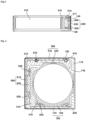
- FIG 1 is a perspective view of a lens driving device according to this embodiment
- FIG 2 is a cross-sectional view taken along line A-A of FIG 1
- FIG 3 is a cross-sectional view taken along line B-B of FIG 1
- FIG 4 is a cross-sectional view taken in a direction perpendicular to an optical axis of the lens driving device according to this embodiment
- FIG 5 is a cross-sectional perspective view illustrating an arranged structure of a first ball in the lens driving device according to this embodiment
- FIG 6 is a cross-sectional perspective view illustrating an arranged structure of a second ball in the lens driving device according to this embodiment
- FIG 7 is a cross-sectional perspective view illustrating an arranged structure of a third ball in the lens driving device according to this embodiment
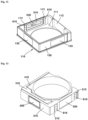
- FIG 8 is an exploded perspective view of the lens driving device according to this embodiment
- FIG 9 is an exploded perspective view of the lens driving device when viewed in a direction different from that in FIG 8
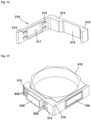
- FIG 10 is a perspective view illustrating a
- a lens driving device 10 may be a voice coil motor (VCM).
- the lens driving device 10 may be a lens driving motor.
- the lens driving device 10 may be a lens driving actuator.
- the lens driving device 10 may comprise an AF module.
- the lens driving device 10 may comprise an OIS module.
- the lens driving device 10 may comprise a fixed unit 100.
- the fixed unit 100 may be a portion that is relatively fixed when the movable unit moves.
- the movable unit may move relative to the fixed unit 100.
- the lens driving device 10 may comprise a base 110.
- the fixed unit 100 may comprise the base 110.
- the base 110 may be disposed below a first holder 210.
- the base 110 may be disposed under a second holder 310.
- the base 110 may be disposed under a third holder 410.
- the base 110 may be coupled to a cover 140.
- the first holder 210, the second holder 310, and the third holder 410 may be disposed on the base 110.
- the first holder 210, the second holder 310, and the third holder 410 may be disposed on a lower plate 111 of the base 110.
- the base 110 may comprise the lower plate 111.
- the base 110 may comprise a side plate 112.
- the side plate 112 of the base 110 may be a 'side portion'.
- the side plate 112 of the base 110 may extend from a top surface of the lower plate 111.
- the side plate 112 of the base 110 may comprise a plurality of side plates.
- the side plate 112 of the base 110 may comprise four side plates.
- the base 110 may comprise a first side portion and a second side portion, which are disposed opposite to each other, and a third side portion and a fourth side portion, which are disposed opposite to each other.
- the second coil 610 may be disposed at a position corresponding to the third side portion of the base 110.
- a distance between an optical axis and the fourth side portion of the base 110 may be closer than a distance between the optical axis and the third side portion of the base 110. That is, the optical axis may be disposed to be biased from a central axis of the base 110 to the fourth side portion of the base 110.
- the base 110 may comprise a groove 113.
- the groove 113 may be a 'first ball accommodation groove'.
- the first ball 810 may be disposed in the groove 113.
- the groove 113 may be in direct contact with the first ball 810.
- the groove 113 may be disposed in an optical axis direction.
- the groove 113 may comprise a plurality of grooves.
- the groove 113 may comprise two grooves.
- the two grooves may be disposed parallel to each other.
- the groove 113 may comprise a first groove that is in contact with the first ball 810 at two points, and a second groove that is in contact with the first ball 810 at one point.
- both the first groove and the second groove may be in contact with the first ball 810 at two points.
- the lens driving device 10 may comprise a substrate 120.
- the fixed unit 100 may comprise a substrate 120.
- the substrate 120 may be disposed on the base 110.
- the substrate 120 may be disposed on the side plate 112 of the base 110.
- the substrate 120 may be disposed on an outer surface of the side plate 112 of the base 112.
- the substrate 120 may be a circuit board.
- the substrate 120 may be a printed circuit board.
- the substrate 120 may comprise a flexible printed circuit board (FPCB).
- the substrate 120 may be disposed parallel to the optical axis.
- the substrate 120 may be folded.
- the substrate 120 may be folded several times.
- the substrate 120 may be folded twice.
- the substrate 120 may comprise a first portion and a third portion, which are disposed opposite each other, and a second portion connecting the first portion to the third portion.
- the first coil 510 may be disposed on the first portion of the substrate 120.
- the second coil 610 may be disposed on the second portion of the substrate 120.
- the third coil 710 may be disposed on the third portion of the substrate 120.
- the substrate 120 may comprise a body part.
- the coils 510, 610, and 710 may be disposed in the body part.
- the substrate 120 may comprise a terminal part 121.
- the terminal part 121 may extend downward from the body part.
- the terminal part 121 may be disposed at a lower portion of the substrate 120.
- the terminal part 121 may protrude downward from the base 110.
- the terminal part 121 may comprise a terminal.
- the terminal part 121 may comprise a plurality of terminals.
- the plurality of terminals of the substrate 120 may be electrically connected to a driver IC 530.
- the plurality of terminals of the substrate 120 may be electrically connected to a sensor 630 and a sensor 730.
- the plurality of terminals of the substrate 120 may be electrically connected to the second coil 610 and the third coil 710.
- the terminal part 121 may be coupled to a printed circuit board 50.
- the lens driving device 10 may comprise a yoke 130.
- the fixed unit 100 may comprise the yoke 130.
- the yoke 130 may be an 'attractive member'.
- the yoke 130 may be made of a metal. Attractive force may be generated between the yoke 130 and each of magnets 520, 620, and 720.
- the balls 810, 820, and 830 may be pressed by the attractive force between the yoke 130 and the magnets 520, 620, and 720.
- the yoke 130 may be disposed on the substrate 120.
- the yoke 130 may be disposed on an outer surface of the substrate 120.
- the yoke 130 may comprise a plurality of yokes.
- the yoke 130 may comprise three yokes.
- the yoke 130 may comprise first to third yokes 131, 132, and 133.
- the first to third yokes 131, 132, and 133 may be spaced apart from each other.
- the yoke 130 may comprise the first yoke 131.
- the first yoke 131 may be an 'AF yoke'.
- the first yoke 131 may be disposed at the first portion of the substrate 120.
- the first yoke 131 may be disposed on an outer surface of the first portion of the substrate 120.
- the first yoke 131 may be disposed at a position corresponding to the first magnet 520. Attractive force may be generated between the first yoke 131 and the first magnet 520.
- the first ball 810 may be pressed by the attractive force between the first yoke 131 and the first magnet 520.
- the first ball 810 may be pressed between the first holder 210 and the base 110 by the attractive force between the first yoke 131 and the first magnet 520.
- the yoke 130 may comprise the second yoke 132.
- the second yoke 132 may be an 'OIS-x yoke'.
- the second yoke 132 may be disposed at the second portion of the substrate 120.
- the second yoke 132 may be disposed on an outer surface of the second portion of the substrate 120.
- the second yoke 132 may be disposed at a position corresponding to the second magnet 620.
- Attractive force may be generated between the second yoke 132 and the second magnet 620.
- the second ball 820 may be pressed by the attractive force between the second yoke 132 and the second magnet 620.
- the second ball 820 may be pressed between the second holder 310 and the first holder 210 by the attractive force between the second yoke 132 and the second magnet 620.
- the yoke 130 may comprise the third yoke 133.
- the third yoke 133 may be an 'OIS-y yoke'.
- the third yoke 133 may be disposed at the second portion of the substrate 120.
- the third yoke 133 may be disposed on the outer surface of the second portion of the substrate 120.
- the third yoke 133 may be disposed at a position corresponding to the third magnet 720.
- Attractive force may be generated between the third yoke 133 and the third magnet 720.
- the third ball 830 may be pressed by the attractive force between the third yoke 133 and the third magnet 720.
- the third ball 830 may be pressed between the third holder 410 and the second holder 310 by the attractive force between the third yoke 133 and the third magnet 720.
- the lens driving device 10 may comprise the cover 140.
- the fixed unit 100 may comprise the cover 140.
- the cover 140 may be disposed on the base 110.
- the cover 140 may be coupled to the base 110.
- the cover 140 may be fixed to the base 110.
- the cover 140 may accommodate the first holder 210 therein.
- the cover 140 may accommodate the second holder 310 therein.
- the cover 140 may accommodate the third holder 410 therein.
- the cover 140 may be a shield member.
- the cover 140 may be a shield may.
- the cover 140 may comprise the upper plate 141.
- the upper plate 141 may be disposed on the movable unit. Upward movement of the movable unit may be limited by the movable unit that is in contact with the upper plate 141.
- the upper plate 141 may comprise a hole through which light passes.
- the cover 140 may comprise the side plate 142.
- the side plate 142 may extend from the upper plate 141.
- the side plate 142 may be disposed on the base 110.
- the side plate 142 may be disposed on a stepped portion that protrudes from a lower end of the outer surface of the base 110.
- the side plate 142 may comprise a plurality of side plates.
- the side plate 142 may comprise four side plates.
- the side plate 142 may comprise a first side plate and a second side plate, which are disposed opposite each other, and a third side plate and a fourth side plate, which are disposed opposite each other.
- the lens driving device 10 may comprise the movable unit.
- the movable unit may be disposed on the fixed unit 100.
- the movable unit may be disposed within the fixed unit 100.
- the movable unit may be disposed on the fixed unit 100.
- the movable unit may be movably disposed on the fixed unit 100.
- the movable unit may move relative to the fixed unit 100 by the driving unit.
- the movable unit may move during an AF operation.
- the movable unit may move during an OIS operation.
- a lens may be coupled to the movable unit.
- the lens driving device 10 may comprise a first movable unit 200.
- the first movable unit 200 may be an 'AF movable unit'.
- the first movable unit 200 may be disposed on the fixed unit 100.
- the first movable unit 200 may be disposed within the fixed unit 100.
- the first movable unit 200 may be disposed on the fixed unit 100.
- the first movable unit 200 may be disposed between the fixed unit 100 and the second movable unit 300.
- the first movable unit 200 may be disposed between the fixed unit 100 and the third movable unit 400.
- the first movable unit 200 may be movably disposed on the fixed unit 100.
- the first movable unit 200 may move in the optical axis direction with respect to the fixed unit 100 by the first driving unit 500.
- the first movable unit 200 may move during the AF operation
- the lens driving device 10 may comprise the first holder 210.
- the first movable unit 200 may comprise the first holder 210.
- the first holder 210 may be an 'AF holder'.
- the first holder 210 may be an 'AF carrier'.
- the first holder 210 may be disposed within the base 110.
- the first holder 210 may be disposed on the base 110.
- the first holder 210 may be disposed inside the cover 140.
- the first holder 210 may be disposed between the base 110 and the second holder 310.
- the first holder 210 may be disposed between the base 110 and the third holder 410.
- the first holder 210 may be disposed to be movable in the optical axis direction.
- the first holder 210 may not overlap both the second holder 310 and the third holder 410.
- the first holder 210 may overlap the second holder 310 and the third holder 410 in a direction perpendicular to the optical axis.
- a stopper may be disposed on the first holder 210.
- the stopper of the first holder 210 may overlap at least one of the second holder 310 and the third holder 410 in the optical axis direction.
- the first holder 210 may comprise a hole 211.
- the hole 211 may be a 'second holder avoidance hole'.
- the hole 211 may be defined in the side plate of the first holder 210.
- the hole 211 may pass through the first holder 210 in the direction perpendicular to the optical axis.
- the hole 211 may be defined as a groove that is recessed from a top surface of the first holder 210 or as a groove that is recessed from a bottom surface.
- a portion of the second holder 310 may be disposed in the hole 211.
- the second magnet 620 may be disposed in the hole 211.
- the first holder 210 may comprise a first groove 212.
- the first groove 212 may be a 'first ball accommodation groove'.
- the first ball 810 may be disposed in the first groove 212.
- the first groove 212 may be in direct contact with the first ball 810.
- the first groove 212 may be disposed in the optical axis direction.
- the first groove 212 may comprise a plurality of grooves.
- the first groove 212 may comprise two grooves.
- the two grooves may be disposed parallel to each other.
- the first groove 212 may comprise a first groove that is in contact with the first ball 810 at two points, and a second groove that is in contact with the first ball 810 at one point. As a modified example, both the first groove and the second groove may be in contact with the first ball 810 at two points.
- the first holder 210 may comprise a second groove 213.
- the second groove 213 may be a 'second ball accommodation groove'.
- the second ball 820 may be disposed in the second groove 213.
- the second groove 213 may be in direct contact with the second ball 820.
- the second groove 213 may be disposed in the direction perpendicular to the optical axis.
- the second groove 213 may comprise a plurality of grooves.
- the second groove 213 may comprise four grooves.
- the second groove 213 may comprise a first groove that is in contact with the second ball 820 at two points and a second groove that is in contact with the second ball 820 at one point. As a modified example, both the first groove and the second groove may be in contact with the second ball 820 at two points.
- the first holder 210 may comprise a groove 214.
- the groove 214 may be a 'magnet accommodation groove'.
- the groove 214 may be defined in the outer surface of the first holder 210.
- the first magnet 520 may be disposed in the groove 214.
- the groove 214 may be defined in a shape corresponding to the first magnet 520.
- the first holder 210 may comprise a groove 215.
- the groove 215 may be defined concavely in an inner surface of the first holder 210.
- the third holder 410 may be disposed in the groove 215.
- the first magnet 520 may be disposed at an opposite side of the groove 215.
- the lens driving device 10 may comprise the second movable unit 300.
- the second movable unit 300 may be an 'OIS-x movable unit'.
- the second movable unit 300 may be disposed on the fixed unit 100.
- the second movable unit 300 may be disposed within the fixed unit 100.
- the second movable unit 300 may be disposed on the fixed unit 100.
- the second movable unit 300 may be disposed within the first movable unit 200.
- the second movable unit 300 may be disposed between the fixed unit 100 and the third movable unit 400.
- the second movable unit 300 may be disposed between the first movable unit 200 and the third movable unit 400.
- the second movable unit 300 may be disposed to be movable.
- the second movable unit 300 may move in the x-axis direction perpendicular to the optical axis with respect to the fixed unit 100 and the first movable unit 200 by the second driving unit 600.
- the second movable unit 300 may move during the OIS operation.
- the lens driving device 10 may comprise the second holder 310.
- the second movable unit 300 may comprise the second holder 310.
- the second holder 310 may be an 'OIS-x holder'.
- the second holder 310 may be an 'OIS-x carrier'.
- the second holder 310 may be disposed within the first holder 210.
- the second holder 310 may be disposed within the base 110.
- the second holder 310 may be disposed on the base 110.
- the second holder 310 may be disposed inside the cover 140.
- the second holder 310 may be disposed between the base 110 and the third holder 410.
- the second holder 310 may be disposed between the first holder 210 and the third holder 410.
- the second holder 310 may be disposed to be movable in the x-axis direction perpendicular to the optical axis.
- the second holder 310 may comprise a portion disposed between the first holder 210 and the third holder 410 in the second direction.
- the second holder 310 may comprise a hole 311.
- the hole 311 may be a 'third holder avoidance hole'.
- the hole 311 may be defined in a side plate of the second holder 310.
- the hole 311 may pass through the second holder 310 in the direction perpendicular to the optical axis.
- the hole 311 may be defined as a groove that is recessed from a top surface of the first holder 310 or as a groove that is recessed from a bottom surface.
- a portion of the third holder 410 may be disposed in the hole 311.
- the third magnet 720 may be disposed in the hole 311.
- the second holder 310 may comprise a first groove 312.
- the first groove 312 may be a 'second ball accommodation groove'.
- the second ball 820 may be disposed in the first groove 312.
- the first groove 312 may be in direct contact with the second ball 820.
- the first groove 312 may be disposed in the direction perpendicular to the optical axis.
- the first groove 312 may comprise a plurality of grooves.
- the first groove 312 may comprise four grooves.
- the first groove 312 may comprise a first groove that is in contact with the second ball 820 at two points and a second groove that is in contact with the second ball 820 at one point. As a modified example, both the first groove and the second groove may be in contact with the second ball 820 at two points.
- the second holder 310 may comprise a second groove 313.
- the second groove 313 may be a 'third ball accommodation groove'.
- the third ball 830 may be disposed in the second groove 313.
- the second groove 313 may be in direct contact with the third ball 830.
- the second groove 313 may be disposed in the direction perpendicular to the optical axis.
- the second groove 313 may comprise a plurality of grooves.
- the second groove 313 may comprise four grooves.
- the second groove 313 may comprise a first groove that is in contact with the third ball 830 at two points and a second groove that in contact with the third ball 830 at one point. As a modified example, both the first groove and the second groove may be in contact with the third ball 830 at two points.
- the second holder 310 may comprise a groove 314.
- the groove 314 may be a 'magnet accommodation groove'.
- the groove 314 may be defined in an outer surface of the second holder 310.
- the second magnet 620 may be disposed in the groove 314.
- the groove 314 may be defined in a shape corresponding to the second magnet 620.
- the lens driving device 10 may comprise a third movable unit 400.
- the third movable unit 400 may be an 'OIS-y movable unit'.
- the third movable unit 400 may be disposed on the fixed unit 100.
- the third movable unit 400 may be disposed within the fixed unit 100.
- the third movable unit 400 may be disposed on the fixed unit 100.
- the third movable unit 400 may be disposed within the first movable unit 200.
- the third movable unit 400 may be disposed within the second movable unit 300.
- the third movable unit 400 may be disposed to be movable.
- the third movable unit 400 may move in the y-axis direction perpendicular to both the optical axis and the x-axis with respect to the fixed unit 100, the first movable unit 200, and the second movable unit 300 by the third driving unit 700.
- the third movable unit 400 may move during the OIS operation.
- the lens driving device 10 may comprise a third holder 410.
- the third movable unit 400 may comprise the third holder 410.
- the third holder 410 may be a 'bobbin'.
- the third holder 410 may be an 'OIS-y holder'.
- the third holder 410 may be an 'OIS-y carrier'.
- the third holder 410 may be disposed within the second holder 310.
- the third holder 410 may be disposed within the first holder 210.
- the third holder 410 may be disposed within the base 110.
- the third holder 410 may be disposed on the base 110.
- the third holder 410 may be disposed inside the cover 140.
- the third holder 410 may be disposed to be movable in the y-axis direction perpendicular to both the optical axis and the x-axis.
- the third holder 410 may comprise a groove 411.
- the groove 411 may be a 'third ball accommodation groove'.
- the third ball 830 may be disposed in the groove 411.
- the groove 411 may be in direct contact with the third ball 830.
- the groove 411 may be defined in the direction perpendicular to the optical axis.
- the groove 411 may comprise a plurality of grooves.
- the groove 411 may comprise four grooves.
- the groove 411 may comprise a first groove that is in contact with the third ball 830 at two points, and a second groove that is in contact with the third ball 830 at one point. As a modified example, both the first groove and the second groove may be in contact with the third ball 830 at two points.
- the third holder 410 may comprise a groove 414.
- the groove 414 may be a 'magnet accommodation groove'.
- the groove 414 may be defined in an outer surface of the third holder 410.
- the third magnet 720 may be disposed in the groove 414.
- the groove 414 may be defined in a shape corresponding to the third magnet 720.
- the lens driving device 10 may comprise a driving unit.
- the driving unit may move the movable unit relative to the fixed unit.
- the driving unit may comprise an AF driving unit.
- the driving unit may comprise an OIS driving unit.
- the driving unit may comprise a coil and a magnet.
- the lens driving device 10 may comprise the first driving unit 500.
- the first driving unit 500 may be an 'AF driving unit'.
- the first driving unit 500 may move the first holder 210 in the optical axis direction.
- the first driving unit 500 may move the first holder 210 in the optical axis direction through electromagnetic force.
- the first driving unit 500 may comprise a coil and a magnet.
- the lens driving device 10 may comprise a first coil 510.
- the first driving unit 500 may comprise the first coil 510.
- the first coil 510 may be an 'AF coil'.
- the first coil 510 may interact with the first magnet 520.
- the first coil 510 may move the first magnet 520 in the optical axis direction.
- the first coil 510 may move the first magnet 520 in the optical axis direction through the interaction with the first magnet 520.
- the first coil 510 may face the first magnet 520.
- the first coil 510 may face the first magnet 520.
- the first coil 510 may be disposed at a position corresponding to the first magnet 520.
- the first coil 510 may overlap the first magnet 520 in the direction perpendicular to the optical axis.
- the first coil 510 may be disposed on the substrate 120.
- the first coil 510 may be disposed on the base 110.
- the first coil 510 may be disposed on the fixed unit 100.
- the lens driving device 10 may comprise the first magnet 520.
- the first driving unit 500 may comprise the first magnet 520.
- the first magnet 520 may be an 'AF magnet'.
- the first magnet 520 may be disposed on the first holder 210.
- the first magnet 520 may be disposed on an outer surface of the first holder 210.
- the first magnet 520 may be fixed to the first holder 210.
- the first magnet 520 may be coupled to the first holder 210.
- the first magnet 520 may be bonded to the first holder 210 with an adhesive.
- the first magnet 520 may be disposed inside the cover 140.
- the first magnet 520 may interact with the first coil 510.
- the first magnet 520 may electromagnetically interact with the first coil 510.
- the first magnet 520 may be disposed at a position corresponding to the first coil 510.
- the first magnet 520 may face the first coil 510.
- the first magnet 520 may be opposite to the first coil 510.
- the first magnet 520 may overlap the first coil 510 in the direction perpendicular to the optical axis.
- the first magnet 520 may be a four-pole magnet.
- the first magnet 520 may comprise a four-pole magnetization magnet.
- the first magnet 520 may comprise a first magnet part comprising a N pole and a S pole, and a second magnet part comprising a N pole and a S pole.
- the first magnet part and the second magnet part may be disposed vertically.
- the first magnet part and the second magnet part may be spaced apart from each other in the vertical direction, and a neutral part may be disposed between the first magnet part and the second magnet part.
- the lens driving device 10 may comprise a driver IC 530.
- the first driving unit 500 may comprise the driver IC 530.
- the driver IC 530 may be an 'AF driver IC'.
- the driver IC 530 may be disposed on the substrate 120.
- the driver IC 530 may comprise a sensing part that detects the first magnet 520.
- the sensing part may comprise a Hall element (Hall IC).
- the sensing part may comprise a Hall sensor.
- the driver IC 530 may be electrically connected to the first coil 510.
- the driver IC 530 may supply current to the first coil 510.
- the driver IC 530 may detect movement of the first magnet 520. A movement amount or position of the first magnet 520 detected by the driver IC 530 may be used for feedback of auto focus driving.
- the driver IC 530 may be disposed within the first coil 510.
- the driver IC 530 may overlap the neutral part of the first magnet 520 in the direction perpendicular to the optical axis.
- the driver IC 530 may be disposed on the outside of the first coil 510.
- the lens driving device 10 may comprise a Hall sensor. That is, the lens driving device 10 may comprise the Hall sensor instead of the driver IC 530.
- the lens driving device 10 may comprise the second driving unit 600.
- the second driving unit 600 may be an 'OIS-x driving unit'.
- the second driving unit 600 may move the second holder 310 in the first direction perpendicular to the optical axis.
- the second driving unit 600 may move the second holder 310 in a first direction perpendicular to the optical axis through electromagnetic force.
- the second driving unit 600 may comprise a coil and a magnet.
- the lens driving device 10 may comprise the second coil 610.
- the second driving unit 600 may comprise the second coil 610.
- the second coil 610 may be an 'OIS-x coil'.
- the second coil 610 may interact with the second magnet 620.
- the second coil 610 may move the second magnet 620 in the x-axis direction perpendicular to the optical axis.
- the second coil 610 may move the second magnet 620 in the x-axis direction through the interaction with the second magnet 620.
- the second coil 610 may face the second magnet 620.
- the second coil 610 may be opposite to the second magnet 620.
- the second coil 610 may be disposed at a position corresponding to the second magnet 620.
- the second coil 610 may overlap the second magnet 620 in the direction perpendicular to the optical axis.
- the second coil 610 may be disposed on the substrate 120.
- the second coil 610 may be disposed on the base 110.
- the second coil 610 may be disposed on the fixed unit 100.
- the lens driving device 10 may comprise the second magnet 620.
- the second driving unit 600 may comprise the second magnet 620.
- the second magnet 620 may be an 'OIS-x magnet'.
- the second magnet 620 may be disposed on the second holder 310.
- the second magnet 620 may be disposed on an outer surface of the second holder 310.
- the second magnet 620 may be fixed to the second holder 310.
- the second magnet 620 may be coupled to the second holder 310.
- the second magnet 620 may be bonded to the second holder 310 with an adhesive.
- the second magnet 620 may be disposed inside the cover 140.
- the second magnet 620 may interact with the second coil 610.
- the second magnet 620 may electromagnetically interact with the second coil 610.
- the second magnet 620 may be disposed at a position corresponding to the second coil 610.
- the second magnet 620 may face the second coil 610.
- the second magnet 620 may be opposite to the second coil 610.
- the second magnet 620 may overlap the second coil 610 in the direction perpendicular to the optical axis.
- the second magnet 620 may be disposed in the hole 211 of the first holder 210.
- the second magnet 620 may overlap the first holder 210 in the first direction.
- the second magnet 620 may overlap the first holder 210 in the optical axis direction.
- the second magnet 610 may be a four-pole magnet.
- the second magnet 620 may comprise a four-pole magnetization magnet.
- the second magnet 620 may comprise a first magnet part comprising a N pole and a S pole, and a second magnet part comprising a N pole and a S pole.
- the first magnet part and the second magnet part may be disposed horizontally.
- the first magnet part and the second magnet part may be spaced apart from each other in the horizontal direction, and a neutral part may be disposed between the first magnet part and the second magnet part.
- the lens driving device 10 may comprise the sensor 630.
- the second driving unit 600 may comprise the sensor 630.
- the sensor 630 may be an 'OIS-x sensor'.
- the sensor 630 may be disposed on the substrate 120.
- the sensor 630 may comprise a Hall sensor.
- the sensor 630 may detect the second magnet 620.
- the sensor 630 may detect magnetic force of the second magnet 620.
- the sensor 630 may be disposed within the second coil 610.
- the sensor 630 may overlap the second coil 610 in the optical axis direction.
- the sensor 630 may face the second magnet 620.
- the sensor 630 may be disposed at a position corresponding to the second magnet 620.
- the sensor 630 may detect movement of the second magnet 620.
- An amount of movement or position of the second magnet 620 detected by the sensor 630 may be used for feedback of the optical image stabilization driving in the x-axis direction.
- the lens driving device 10 may comprise the third driving unit 700.
- the third driving unit 700 may be an 'OIS-y driving unit'.
- the third driving unit 700 may move the third holder 410 in a second direction that is perpendicular to both the optical axis and the first direction.
- the third driving unit 700 may move the third holder 410 in the second direction perpendicular to both the optical axis and the first direction through electromagnetic force.
- the third driving unit 700 may comprise a coil and a magnet.
- the lens driving device 10 may comprise the third coil 710.
- the third driving unit 700 may comprise the third coil 710.
- the third coil 710 may be an 'OIS-y coil'.
- the third coil 710 may interact with the third magnet 720.
- the third coil 710 may be disposed at an opposite side of the first coil 510 with respect to the optical axis.
- the third coil 710 may move the third magnet 720 in the y-axis direction perpendicular to both the optical axis and the x-axis.
- the third coil 710 may move the third magnet 720 in the y-axis direction through interaction with the third magnet 720.
- the third coil 710 may face the third magnet 720.
- the third coil 710 may be opposite to the third magnet 720.
- the third coil 710 may be disposed at a position corresponding to the third magnet 720.
- the third coil 710 may overlap the third magnet 720 in the direction perpendicular to the optical axis.
- the third coil 710 may be disposed on the substrate 120.
- the third coil 710 may be disposed on the base 110.
- the third coil 710 may be disposed on the fixed unit 100.
- the lens driving device 10 may comprise the third magnet 720.
- the third driving unit 700 may comprise the third magnet 720.
- the third magnet 720 may be an 'OIS-y magnet'.
- the third magnet 720 may be disposed on the third holder 410.
- the third magnet 720 may be disposed on an outer surface of the third holder 410.
- the third magnet 720 may be fixed to the third holder 410.
- the third magnet 720 may be coupled to the third holder 410.
- the third magnet 720 may be bonded to the third holder 410 with an adhesive.
- the third magnet 720 may be disposed inside the cover 140.
- the third magnet 720 may interact with the third coil 710.
- the third magnet 720 may electromagnetically interact with the third coil 710.
- the third magnet 720 may be disposed at a position corresponding to the third coil 710.
- the third magnet 720 may face the third coil 710.
- the third magnet 720 may be opposite to the third coil 710.
- the third magnet 720 may overlap the third coil 710 in the direction perpendicular to the optical axis.
- the third magnet 720 may be disposed in the hole 311 of the second holder 310.
- the third magnet 720 may overlap the second holder 310 in the second direction.
- the third magnet 720 may overlap the second holder 310 in the optical axis direction.
- the third magnet 720 may be a four-pole magnet.
- the third magnet 720 may comprise a four-pole magnetization magnet.
- the third magnet 720 may comprise a first magnet part comprising a N pole and a S pole, and a second magnet part comprising a N pole and a S pole.
- the first magnet part and the second magnet part may be disposed horizontally.
- the first magnet part and the second magnet part may be spaced apart from each other in the horizontal direction, and a neutral part may be disposed between the first magnet part and the second magnet part.
- a distance between the third coil 710 and the third magnet 720 may be maintained constantly.
- the lens driving device 10 may comprise the sensor 730.
- the third driving unit 700 may comprise the sensor 730.
- the sensor 730 may be an 'OIS-y sensor'.
- the sensor 730 may be disposed on the substrate 120.
- the sensor 730 may comprise a Hall sensor.
- the sensor 730 may detect the third magnet 720.
- the sensor 730 may detect magnetic force of the third magnet 720.
- the sensor 730 may be disposed within the third coil 710.
- the sensor 730 may overlap with the third coil 710 in the optical axis direction.
- the sensor 730 may face the third magnet 720.
- the sensor 730 may be disposed at a position corresponding to the third magnet 720.
- the sensor 730 may detect movement of the third magnet 720.
- An amount of movement or position of the third magnet 720 detected by the sensor 730 may be used for feedback of the optical image stabilization driving in the y-axis direction.
- the lens driving device 10 may comprise a guide member.
- the guide member may comprise a ball.
- the guide member may comprise a pin.
- the guide member may comprise a cylindrical member. The guide member may guide the movement of the movable unit relative to the fixed unit 100 in a specific direction.
- the lens driving device 10 may comprise the first ball 810.
- the first ball 810 may be an 'AF guide ball'.
- the first ball 810 may guide the movement of the first holder 210 relative to the base 110 in the optical axis direction.
- the first ball 810 may be disposed between the base 110 and the first holder 210.
- the first ball 810 may be disposed between the base 110 and the first holder 210 in the first direction.
- the first ball 810 may be disposed in the groove 113 of the base 110.
- the first ball 810 may be disposed in the first groove 212 of the first holder 210.
- the first ball 810 may comprise a first-1 ball that is in contact with the base 110 and the first holder 210 at four points, and a first-2 ball that is in contact with the base 110 and the first holder 210 at three points.
- the first ball 810 may be a spherical shape.
- the first ball 810 may be made of a metal. Grease may be applied to a surface of the first ball 810.
- the first ball 810 may comprise a plurality of balls.
- the first ball 810 may comprise six balls. Three first balls 810 may be disposed at one side of the first magnet 520, and the remaining three first balls 810 may be disposed at the other side of the first magnet 520.
- the lens driving device 10 may comprise the second ball 820.
- the second ball 820 may be an 'OIS-x guide ball'.
- the second ball 820 may guide the movement of the second holder 310 relative to the first holder 210 in the x-axis direction.
- the second ball 820 may be disposed between the first holder 210 and the second holder 310.
- the second ball 820 may be disposed between the first holder 210 and the second holder 310 in the second direction.
- An entire area from a lower end to an upper end of the second ball 820 may overlap both the first holder 210 and the second holder 310 in the second direction.
- An entire area of the second ball 820 may overlap the first holder 210 and the second holder 310 in the second direction.
- the second ball 820 may be disposed between an inner surface of the first holder 210 and an outer surface of the second holder 310. When viewed from the outside of the second holder 310, the second ball 820 may overlap the second magnet
- the second ball 820 may be disposed in the second groove 213 of the first holder 210.
- the second ball 820 may be disposed in the first groove 312 of the second holder 310.
- the second ball 820 may comprise a first-1t ball that is in contact with the first holder 210 and the second holder 310 at four points, and a first-2 ball that is in contact with the first holder 210 and the second holder 310 at three points.
- the second ball 820 may have a spherical shape.
- the second ball 820 may be made of a metal. Grease may be applied to a surface of the second ball 820.
- the second ball 820 may comprise a plurality of balls.
- the second ball 820 may comprise four balls. Two second balls 820 may be disposed at one side of the second magnet 620, and the remaining two second balls 820 may be disposed at the other side of the second magnet 620.
- the lens driving device 10 may comprise the third ball 830.
- the third ball 830 may be an 'OIS-y guide ball'.
- the third ball 830 may guide the movement of the third holder 410 relative to the second holder 310 in the y-axis direction.
- the third ball 830 may be disposed between the second holder 310 and the third holder 410.
- the third ball 830 may be disposed between the second holder 310 and the third holder 410 in the first direction.
- An entire area from a lower end to an upper end of the third ball 830 may overlap both the second holder 310 and the third holder 410 in the first direction.
- the third ball 830 may be disposed between an inner surface of the second holder 310 and an outer surface of the third holder 410.
- the third ball 830 may overlap the third magnet 720 in the horizontal direction.
- the horizontal direction may be any direction perpendicular to the optical axis.
- at least a portion of the third ball 830 may overlap the third magnet 720 in the second direction.
- a portion of the third ball 830 may overlap the second holder 310 in the first direction. Another portion of the third ball 830 may overlap the third holder 410 in the first direction. A portion of the third ball 830 may overlap the second holder 310 toward an upper side in the first direction. Another portion of the third ball 830 may overlap the third holder 410 toward an upper side in the first direction. A portion of the third ball 830 may overlap the second holder 310 toward a lower side in the first direction. Another portion of the third ball 830 may overlap the third holder 410 toward the lower side in the first direction.
- the third ball 830 may be disposed in the second groove 313 of the second holder 310.
- the third ball 830 may be disposed in the groove 411 of the third holder 410.
- the third ball 830 may comprise a first-1 ball that is in contact with the second holder 310 and the third holder 410 at four points, and a first-2 ball that is in contact with the second holder 310 and the third holder 410 at three points.
- the third ball 830 may be a spherical shape.
- the third ball 830 may be made of a metal. Grease may be applied to a surface of the third ball 830.
- the third ball 830 may comprise a plurality of balls.
- the third ball 830 may comprise four balls. Two third balls 830 may be disposed at one side of the third magnet 630, and the remaining two third balls 830 may be disposed at the other side of the third magnet 630.
- FIGS. 18 to 20 are views for explaining the auto focus driving of the lens driving device according to this embodiment.
- FIG 18 is a cross-sectional view illustrating a configuration of the movable unit in an initial state in which current is not applied to a first coil.
- FIG 19 is a cross-sectional view illustrating a state in which forward current is applied to the first coil so that the movable unit moves upward in the optical axis direction.
- FIG 20 is a cross-sectional view illustrating a state in which reverse current is applied to the first coil so that the moving part moves downward in the optical axis direction.
- the movable unit may be disposed at a position spaced apart from both the upper plate 141 of the cover 140 and the base 110 in an initial position at which no current is applied to the first coil 510.
- the movable unit may be the first movable unit 200.
- the movable unit may comprise first to third movable units 200, 300, and 400.
- the first magnet 520 When forward current is applied to the first coil 510, the first magnet 520 may move upward in the optical axis direction due to the electromagnetic interaction between the first coil 510 and the first magnet 520 (see reference symbol A of FIG 19 ).
- the first holder 210 may move upward in the optical axis direction together with the first magnet 520.
- the second holder 310, the third holder 410, and the lens together with the first holder 210 may move upward in the optical axis direction.
- a distance between the lens and the image sensor may be changed, so that a focus of an image formed on the image sensor through the lens may be adjusted.
- the first magnet 520 When reverse current is applied to the first coil 510, the first magnet 520 may move downward in the optical axis direction due to the electromagnetic interaction between the first coil 510 and the first magnet 520 (see reference symbol B of FIG 20 ).
- the first holder 210 may move downward in the optical axis direction together with the first magnet 520.
- the second holder 310, the third holder 410, and the lens together with the first holder 210 may move downward in the optical axis direction.
- a distance between the lens and the image sensor may be changed, so that a focus of an image formed on the image sensor through the lens may be adjusted.
- the sensing part of the driver IC 530 may detect the amount of movement or position of the first magnet 520 by detecting strength of magnetic fields of the first magnet 520.
- the movement amount or position of the first magnet 520 detected by the driver IC 530 may be used for an auto focus feedback control.
- optical image stabilization (OIS) operation of the lens driving device according to this embodiment is described with reference to the drawings.
- FIGS. 21 to 23 are views for explaining the optical image stabilization driving of the lens driving device according to this embodiment.
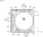
- FIG 21 is a cross-sectional view illustrating a configuration of the movable unit in the initial state in which current is not applied to the second coil and the third coil.
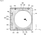
- FIG 22 is a cross-sectional view illustrating a state in which current is applied to the second coil so that the second movable unit and the third movable unit move in the x-axis direction perpendicular to the optical axis.
- FIG 23 is a cross-sectional view illustrating a state in which current is applied to the third coil so that the third movable unit moves in the y-axis direction perpendicular to both the optical axis and the x-axis.
- the movable unit may be disposed at an initial position at which no current is applied to the second coil 610 and the third coil 710.
- the movable unit may be the second movable unit 300 and the third movable unit 400.
- the movable unit may comprise first to third movable units 200, 300, and 400.
- the second magnet 620 When current is applied to the second coil 610, the second magnet 620 may move in the x-axis direction perpendicular to the optical axis due to the electromagnetic interaction between the second coil 610 and the second magnet 620 (see reference symbol A of FIG 22 ).
- the second holder 310 may move in the x-axis direction together with the second magnet 620.
- the third holder 410 and the lens together with the second holder 310 may move in the x-axis direction.
- the forward current is applied to the second coil 610
- the second magnet 620, the second holder 310, the third holder 410, and the lens may move in one direction along the x-axis.
- the reverse current is applied to the second coil 610, the second magnet 620, the second holder 310, the third holder 410, and the lens may move in the other direction along the x-axis.
- the third magnet 720 When current is applied to the third coil 710, the third magnet 720 may move in the y-axis direction perpendicular to the optical axis due to the electromagnetic interaction between the third coil 710 and the third magnet 720 (see reference symbol B of FIG 23 ).
- the third holder 410 may move in the y-axis direction together with the third magnet 720.
- the lens may move in the y-axis direction together with the third holder 410.
- the forward current is applied to the third coil 710
- the third magnet 720, the third holder 410, and the lens may move in one direction along the y-axis.
- the reverse current when the reverse current is applied to the third coil 710, the third magnet 720, the third holder 410, and the lens may move in the other direction along the y-axis.
- the sensor 630 may detect an amount of movement or position of the second magnet 620 by detecting strength of magnetic fields of the second magnet 620.
- the movement amount or position of the second magnet 620 detected by the sensor 630 may be used for an optical image stabilization feedback control in the x-axis direction.
- the sensor 730 may detect an amount of movement or position of the third magnet 720 by detecting strength of magnetic fields of the third magnet 720.
- the movement amount or position of the third magnet 720 detected by the sensor 730 may be used for an optical image stabilization feedback control in the y-axis direction.
- FIG 24 is an exploded perspective view of the camera device according to this embodiment.
- a camera device 10A may comprise a camera module.
- the camera device 10A may comprise a lens module 20.
- the lens module 20 may comprise at least one lens.
- the lens may be disposed at a position corresponding to the image sensor 60.
- the lens module 20 may comprise a lens and a barrel.
- the lens module 20 may be coupled to the holder 210 of the lens driving device 10.
- the lens module 20 may be attached to the holder 210 by screw coupling and/or an adhesive.
- the lens module 20 may move to be integrated with the holder 210.
- the camera device 10A may comprise a filter 30.
- the filter 30 may serve to block light having a specific frequency band from passing through the lens module 20 from being incident into the image sensor 60.
- the filter 30 may be disposed parallel to a x-y plane.
- the filter 30 may be disposed between the lens module 20 and the image sensor 60.
- the filter 30 may be disposed on a sensor base 40.
- the filter 30 may be disposed on the base 110.
- the filter 30 may comprise an infrared filter.
- the infrared filter may block light in an infrared region from being incident into the image sensor 60.
- the camera device 10A may comprise the sensor base 40.
- the sensor base 40 may be disposed between the lens driving device 10 and the printed circuit board 50.
- the sensor base 40 may comprise a protrusion 41 on which the filter 30 is disposed.
- An opening may be defined in a portion of the sensor base 40 on which the filter 30 is disposed so that light passing through the filter 30 is incident into the image sensor 60.
- An adhesive member may bond or adhere the base 310 of the lens driving device 10 to the sensor base 40.
- the adhesive member may additionally serve to prevent foreign substances from being introduced into the lens driving device 10.
- the adhesive material may comprise one or more of epoxy, a thermosetting adhesive, and a UV-curable adhesive.
- the camera device 10A may comprise a printed circuit board (PCB) 50.
- the printed circuit board 50 may be a substrate or a circuit board.
- the lens driving device 10 may be disposed on the printed circuit board 50.
- the sensor base 40 may be disposed between the printed circuit board 50 and the lens driving device 10.
- the printed circuit board 50 may be electrically connected to the lens driving device 10.
- the image sensor 60 may be disposed on the printed circuit board 50.
- the printed circuit board 50 may be provided with various circuits, components, control units, etc. to convert an image formed on the image sensor 60 into an electrical signal and transmit the electrical signal to an external device.
- the camera device 10A may comprise the image sensor 60.
- the image sensor 60 may be configured to form an image by the incident light passing through the lens and the filter 30.
- the image sensor 60 may be mounted on the printed circuit board 50.
- the image sensor 60 may be electrically connected to the printed circuit board 50.
- the image sensor 60 may be coupled to the printed circuit board 50 using a surface mounting technology (SMT).
- SMT surface mounting technology
- the image sensor 60 may be coupled to the printed circuit board 50 by a flip chip technology.
- the image sensor 60 may be disposed so that the optical axis is aligned with the lens. That is, the optical axis of the image sensor 60 and the optical axis of the lens may be aligned with each other.
- the image sensor 60 may convert light irradiated onto an effective image area of the image sensor 60 into an electrical signal.
- the image sensor 60 may be any one of a charge coupled device (CCD), a metal oxide semi-conductor (MOS), a CPD, and a CID.
- CCD charge coupled device
- MOS metal oxide semi-conductor
- CPD CPD
- CID CID
- the camera device 10A may comprise a motion sensor 70.
- the motion sensor 70 may be mounted on the printed circuit board 50.
- the motion sensor 70 may be electrically connected to a control unit 80 through a circuit pattern provided on the printed circuit board 50.
- the motion sensor 70 may output rotational angular velocity information due to the movement of the camera device 10A.
- the motion sensor 70 may comprise a two-axis or three-axis gyro sensor or an angular velocity sensor.
- the camera device 10A may comprise the control unit 80.
- the control unit 80 may be disposed on the printed circuit board 50.
- the control unit 80 may be electrically connected to the coil 330 of the lens driving device 10.
- the control unit 80 may individually control a direction, intensity, and amplitude of current supplied to the coil 330.
- the control unit 80 may control the lens driving device 10 to perform the auto focus function and/or the optical image stabilization function. Furthermore, the control unit 80 may perform the auto focus feedback control and/or the optical image stabilization feedback control for the lens driving device 10.
- the camera device 10A may comprise a connector 90.
- the connector 90 may be electrically connected to the printed circuit board 50.
- the connector 90 may comprise a port for electrical connection with an external device.
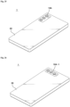
- FIG 25 is a perspective view of an optical instrument according to this embodiment
- FIG 26 is a perspective view illustrating a modified example of an optical instrument.
- An optical instrument 1 may comprise one or more of a mobile phone, a cellular phone, a portable terminal, a mobile terminal, a smart phone, a smart pad, a portable smart device, a digital camera, a laptop computer, a digital broadcasting terminal, a personal digital assistants (PDA), a portable multimedia player (PMP), and a navigation device.
- the optical instrument 1 may comprise any device for taking images or photographs.
- the optical instrument 1 may comprise a main body 20.
- the optical instrument 1 may comprise a camera device 10A.
- the camera device 10A may be disposed on the main body 20.
- the camera device 10A may photograph a subject.
- the optical instrument 1 may comprise a display.
- the display may be disposed on the main body 20.
- the display may output one or more of images and videos captured by the camera device 10A.
- the display may be disposed on a first surface of the main body 20.
- the camera device 10A may be disposed on one or more of a first surface of the main body 20 and a second surface opposite to the first surface.
- the camera device 10A may be provided with a triple camera disposed in a vertical direction.
- the camera device 10A-1 may have a triple camera disposed in a horizontal direction.
Landscapes
- Physics & Mathematics (AREA)
- General Physics & Mathematics (AREA)
- Engineering & Computer Science (AREA)
- Optics & Photonics (AREA)
- Signal Processing (AREA)
- Multimedia (AREA)
- Power Engineering (AREA)
- Chemical & Material Sciences (AREA)
- Electromagnetism (AREA)
- Combustion & Propulsion (AREA)
- Lens Barrels (AREA)
- Adjustment Of Camera Lenses (AREA)
- Studio Devices (AREA)
Abstract
The embodiment relates to a lens driving device comprising: a base; a first holder disposed in the base; a second holder disposed in the first holder; a bobbin disposed in the second holder; a first driving unit for moving the first holder in a z-axis direction along an optical axis; a second driving unit for moving the second holder in a y-axis direction perpendicular to the z-axis direction; and a third driving unit for moving the bobbin in an x-axis direction perpendicular to both the z-axis direction and the y-axis direction. Each of the first to third driving units includes a coil and a magnet.
Description
- This embodiment relates to a lens driving device, a camera device, and an optical instrument.
- A camera device is a device that takes pictures or videos of a subject and is mounted in optical instruments such as smartphones, drones, and vehicles.
- The camera device has an auto focus function that automatically adjusts a focus depending on a distance to the subject. In addition, an optical image stabilization function is applied to prevent the focus from being shaken due to a user's hand shake.
- However, in order to place constitutions such as the magnet and the coil that perform the auto focus function and the optical image stabilization function, a camera having a size larger than a thickness of the smartphone in an optical axis direction is required to cause a problem in which the camera mounted on the smartphone protrudes more than other portions of the smartphone.
(Patent Document 1)KR 10-2015-0118005 A - This embodiment is to provide a camera device having a minimized size in an optical axis direction even through an auto focus function and an optical image stabilization function are provided.
- A lens driving device according to this embodiment may comprise: a base; a first holder disposed in the base; a second holder disposed in the first holder; a bobbin disposed in the second holder; a first driving unit configured to move the first holder in a z-axis direction along an optical axis; a second driving unit configured to move the second holder in a y-axis direction perpendicular to the z-axis direction; and a third driving unit configured to move the bobbin in an x-axis direction perpendicular to the z-axis direction and the y-axis direction, wherein each of the first to third driving units may comprise a coil and a magnet, the first driving unit may comprise a coil coupled to one of the base and the first holder and a magnet coupled to the other of the base and the first holder, the second driving unit may comprise a coil coupled to one of the base and the second holder and a magnet coupled to the other of the base and the second holder, and the third driving unit may comprise a coil coupled to one of the base and the bobbin and a magnet coupled to the other of the base and the bobbin.
- The first holder and the second holder may be separated from each other.
- A first sidewall of the first holder and a first sidewall of the second holder may overlap each other in the x-axis direction and may be disposed at one side of the bobbin.
- The lens driving device may further comprise a first ball disposed between a second sidewall of the first holder and a second sidewall of the base.
- The lens driving device may further comprise a second ball disposed between a first sidewall of the first holder and a first sidewall of the second holder.
- The lens driving device may further comprise a third ball disposed between a second sidewall of the second holder and the bobbin.
- A lens driving device according to this embodiment may comprise: a fixed unit; a first movable unit moving in a z-axis direction along an optical axis relative to the fixed unit; a second movable unit moving in a y-axis direction perpendicular to the z-axis direction; and a third movable unit moving in an x-axis direction perpendicular to the y-axis direction, wherein a first ball may be disposed between a second sidewall of the first movable unit and a second sidewall of the fixed unit, a second ball may be disposed between a first sidewall of the first movable unit and a first sidewall of the second movable unit, and a third ball may be disposed between a second sidewall of the second movable unit and the third movable unit.
- A lens driving device according to this embodiment may comprise: a base; a first holder moving in a z-axis direction along an optical axis relative to the base; a second holder moving in a y-axis direction perpendicular to the z-axis direction; and a bobbin moving in an x-axis direction perpendicular to the y-axis direction, wherein a first ball may be disposed between a second sidewall of the first holder and a second sidewall of the base; a second ball may be disposed between a first sidewall of the first holder and a first sidewall of the second holder, a third ball may be disposed between a second sidewall of the second holder and the bobbin, and the first holder and the second holder may be spaced apart from each other.
- A lens driving device according to this embodiment may comprise: a base; a first holder disposed in the base; a second holder disposed in the first holder; a third holder disposed in the second holder; a first driving unit configured to move the first holder in a direction along an optical axis; a second driving unit configured to move the second holder in a first direction perpendicular to the optical axis; a third driving unit configured to move the third holder in a second direction perpendicular to both the optical axis and the first direction; a first ball disposed between the base and the first holder; a second ball disposed between the first holder and the second holder; and a third ball disposed between the second holder and the third holder, wherein the third ball may be disposed between the second holder and the third holder in the first direction.
- The second ball may be disposed between the first holder and the second holder in the second direction.
- The first driving unit may comprise: a first magnet disposed on the first holder and a first coil that interacts with the first magnet; the second driving unit may comprise a second magnet disposed on the second holder and a second coil that interacts with the second magnet; and the third driving unit may comprise a third magnet disposed on the third holder and a third coil that interacts with the third magnet.
- The lens driving device may comprise a substrate disposed on the base, wherein the substrate may comprise a first portion and a third portion, which are disposed to be opposite to each other, and a second portion configured to connect the first portion to the third portion, wherein the first coil may be disposed at the first portion of the substrate. The second coil may be disposed at the second portion of the substrate, and the third coil may be disposed at the third portion of the substrate.
- The lens driving device may comprise: a first yoke disposed at a position corresponding to the first magnet at the first portion of the substrate; a second yoke disposed at a position corresponding to the second magnet at the second portion of the substrate; and a third yoke disposed at a position corresponding to the third magnet at the third portion of the substrate.
- The third ball may be disposed between an inner surface of the second holder and an outer surface of the third holder.
- An entire area from a lower end to an upper end of the third ball may overlap the second holder and the third holder in the first direction.
- When viewed from the outside of the third holder, the third ball may overlap the third magnet in a horizontal direction.
- The first holder may comprise a hole, and the second magnet may be disposed in the hole of the first holder to overlap the first holder in the first direction.
- The second holder may comprise a hole, and the third magnet may be disposed in the hole of the second holder to overlap the second holder in the second direction.
- The base may comprise a first sidewall and a second sidewall, which are disposed to be opposite to each other, and a third sidewall and a fourth sidewall, which are disposed to be opposite to each other, the second coil may be disposed at a position corresponding to the third sidewall, and a distance between the optical axis and the fourth sidewall of the base may be less than a distance between the optical axis and the third sidewall of the base.
- The second holder may comprise a portion disposed between the first holder and the third holder in the second direction.
- The first holder may not overlap the second holder and the third holder in a direction along the optical axis.
- A camera device according to this embodiment may comprise: a printed circuit board; an image sensor disposed on the printed circuit board; the lens driving device disposed on the printed circuit board; and a lens coupled to the lens driving device.
- An optical instrument according to this embodiment may comprise: a main body; the camera device disposed on the main body according to claim 14; and a display disposed in the main body to output one or more of videos and images captured by the camera device.
- According to this embodiment, the auto focus function and the optical image stabilization function may be performed in the camera device having the minimized size in the optical axis direction.
- That is, according to this embodiment, both the auto focus function and the optical image stabilization function may be performed even in the camera device that does not protrude from the smartphone.
- Furthermore, according to this embodiment, the camera device having the minimized size in the horizontal and vertical directions perpendicular to the optical axis may be provided.
-
-
FIG 1 is a perspective view of a lens driving device according to this embodiment. -
FIG 2 is a cross-sectional view taken along line A-A ofFIG 1 . -
FIG 3 is a cross-sectional view taken along line B-B ofFIG 1 . -
FIG 4 is a cross-sectional view taken in a direction perpendicular to an optical axis of the lens driving device according to this embodiment. -
FIG 5 is a cross-sectional perspective view illustrating an arranged structure of a first ball in the lens driving device according to this embodiment. -
FIG 6 is a cross-sectional perspective view illustrating an arranged structure of a second ball in the lens driving device according to this embodiment. -
FIG 7 is a cross-sectional perspective view illustrating an arranged structure of a third ball in the lens driving device according to this embodiment. -
FIG 8 is an exploded perspective view of the lens driving device according to this embodiment. -
FIG 9 is an exploded perspective view of the lens driving device when viewed in a direction different from that inFIG 8 . -
FIG 10 is a perspective view illustrating a state in which a cover is omitted in the lens driving device according to this embodiment. -
FIG 11 is a perspective view illustrating a fixed unit of the lens driving device according to this embodiment. -
FIG 12 is a perspective view when the lens driving device that is in the state ofFIG 11 is viewed in a direction different from that inFIG 11 . -
FIG 13 is a perspective view illustrating a movable unit of the lens driving device according to this embodiment. -
FIG 14 is a perspective view illustrating a first holder of the lens driving device according to this embodiment. -
FIG 15 is a perspective view illustrating a second movable unit and a third movable unit of the lens driving device according to this embodiment. -
FIG 16 is a perspective view illustrating a second holder of the lens driving device according to this embodiment. -
FIG 17 is a perspective view illustrating a third movable unit of the lens driving device according to this embodiment. -
FIGS. 18 to 20 are views for explaining auto focus driving of the lens driving device according to this embodiment.FIG 18 is a cross-sectional view illustrating a configuration of the movable unit in an initial state in which current is not applied to a first coil.FIG 19 is a cross-sectional view illustrating a state in which forward current is applied to a first coil so that the movable unit moves upward in the optical axis direction.FIG 20 is a cross-sectional view illustrating a state in which reverse current is applied to the first coil so that the movable unit moves downward in the optical axis direction. -
FIGS. 21 to 23 are views for explaining optical image stabilization driving of the lens driving device according to this embodiment.FIG 21 is a cross-sectional view illustrating a configuration of the movable unit in the initial state in which current is not applied to a second coil and a third coil.FIG 22 is a cross-sectional view illustrating a state in which current is applied to the second coil so that the second movable unit and the third movable unit move in an x-axis direction perpendicular to the optical axis.FIG 23 is a cross-sectional view illustrating a state in which current is applied to the third coil so that the third movable unit moves in a y-axis direction perpendicular to both the optical axis and an x-axis. -
FIG 24 is an exploded perspective view of the camera device according to this embodiment. -
FIG 25 is a perspective view of an optical instrument according to this embodiment. -
FIG 26 is a perspective view illustrating a modified example of an optical instrument. - Hereinafter, preferred embodiments of the present invention will be described in detail with reference to the accompanying drawings.
- However, the technical idea of the present invention is not limited to some of the embodiments described, but may be implemented in various different forms, and one or more of the components in embodiments may be selectively combined or substituted for use even within the scope of the technical idea of the present invention.
- In addition, terms (comprising technical and scientific terms) used in the embodiments of the present invention may be interpreted as having a meaning that may be generally understood by a person of ordinary skill in the technical field to which the present invention belongs, unless explicitly and specifically defined and described, and the terms that are commonly used, such as terms defined in a dictionary, may be interpreted in consideration of the contextual meaning of the relevant technology.
- In addition, the terms used in the embodiments of the present invention are for the purpose of describing the embodiments and are not intended to limit the present invention.
- In this specification, the singular may also comprise the plural unless specifically stated otherwise in the phrase, and when it is described as "A and (or at least one) of B, C", it may comprise one or more of all combinations that may be combined with A, B, C.
- In addition, in describing components of the embodiments of the present invention, the terms such as first, second, A, B, (a), (b), etc. may be used. These terms are only intended to distinguish one component from another and are not intended to limit the nature, order, or sequence of the component.
- In addition, when a component is described as being 'connected', 'coupled', or 'linked' to another component, it may comprise not only cases where the component is 'connected', 'coupled', or 'linked' directly to the other component, but also cases in which the component is 'connected', 'coupled', or 'linked' by another component between the component and the other component.
- In addition, when described as being formed or arranged "above (upper)" or "below (lower)" each component, "above (upper)" or "below (lower)" comprises not only the case where the two components are in direct contact with each other, but also the case in which one or more other components are formed or arranged between the two components. In addition, when expressed as "above (upper)" or "below (lower)", it may comprise the meaning of not only the upward direction but also the downward direction based on one component.
- The 'optical axis (see reference symbol OA of
FIG 18 , etc.) direction' used below is defined as the optical axis direction of a lens and/or image sensor coupled to a lens driving device. - The 'vertical direction' used below may be a direction parallel to or the same direction as the optical axis. The vertical direction may correspond to a 'z-axis direction'. The "horizontal direction' used below may refer to a direction perpendicular to the vertical direction. That is, the horizontal direction may be a direction perpendicular to the optical axis. Thus, the horizontal direction may comprise an 'x-axis direction' and a 'y-axis direction'.
- The 'auto focus (AF) function' used below may be defined as a function that automatically focuses on a subject by adjusting a distance from an image sensor by moving a lens along the optical axis according to a distance to the subject so that a clear image of the subject is obtained on the image sensor. In addition, a 'closed-loop auto focus (CLAF) control' is defined as controlling a position of the lens by detecting a distance between the image sensor and the lens to provide feedback in real time, thereby improving accuracy of focus adjustment.
- The 'optical image stabilization (OIS) function' used below is defined as a function that moves or tilts the lens in the direction perpendicular to the optical axis to offset hand shake in order to prevent images or videos from being shaken due to the user's hand shake. In addition, a 'CLAF (closed-loop auto focus) control' is defined as detecting a position of the lens with respect to the image sensor and controlling the feedback of the lens position in real time to improve accuracy of image stabilization.
- Hereinafter, a configuration of the lens driving device according to this embodiment is described with reference to the drawings.
-
FIG 1 is a perspective view of a lens driving device according to this embodiment,FIG 2 is a cross-sectional view taken along line A-A ofFIG 1 ,FIG 3 is a cross-sectional view taken along line B-B ofFIG 1 ,FIG 4 is a cross-sectional view taken in a direction perpendicular to an optical axis of the lens driving device according to this embodiment,FIG 5 is a cross-sectional perspective view illustrating an arranged structure of a first ball in the lens driving device according to this embodiment,FIG 6 is a cross-sectional perspective view illustrating an arranged structure of a second ball in the lens driving device according to this embodiment,FIG 7 is a cross-sectional perspective view illustrating an arranged structure of a third ball in the lens driving device according to this embodiment,FIG 8 is an exploded perspective view of the lens driving device according to this embodiment,FIG 9 is an exploded perspective view of the lens driving device when viewed in a direction different from that inFIG 8 ,FIG 10 is a perspective view illustrating a state in which a cover is omitted in the lens driving device according to this embodiment,FIG 11 is a perspective view illustrating a fixed unit of the lens driving device according to this embodiment,FIG 12 is a perspective view when the lens driving device that is in the state ofFIG 11 is viewed in a direction different from that inFIG 11 ,FIG 13 is a perspective view illustrating a movable unit of the lens driving device according to this embodiment,FIG 14 is a perspective view illustrating a first holder of the lens driving device according to this embodiment,FIG 15 is a perspective view illustrating a second movable unit and a third movable unit of the lens driving device according to this embodiment,FIG 16 is a perspective view illustrating a second holder of the lens driving device according to this embodiment, andFIG 17 is a perspective view illustrating a third movable unit of the lens driving device according to this embodiment. - A
lens driving device 10 may be a voice coil motor (VCM). Thelens driving device 10 may be a lens driving motor. Thelens driving device 10 may be a lens driving actuator. Thelens driving device 10 may comprise an AF module. Thelens driving device 10 may comprise an OIS module. - The
lens driving device 10 may comprise a fixedunit 100. The fixedunit 100 may be a portion that is relatively fixed when the movable unit moves. The movable unit may move relative to the fixedunit 100. - The
lens driving device 10 may comprise abase 110. The fixedunit 100 may comprise thebase 110. The base 110 may be disposed below afirst holder 210. The base 110 may be disposed under asecond holder 310. The base 110 may be disposed under athird holder 410. The base 110 may be coupled to acover 140. Thefirst holder 210, thesecond holder 310, and thethird holder 410 may be disposed on thebase 110. Thefirst holder 210, thesecond holder 310, and thethird holder 410 may be disposed on alower plate 111 of thebase 110. - The base 110 may comprise the
lower plate 111. The base 110 may comprise aside plate 112. Theside plate 112 of the base 110 may be a 'side portion'. Theside plate 112 of the base 110 may extend from a top surface of thelower plate 111. Theside plate 112 of the base 110 may comprise a plurality of side plates. Theside plate 112 of the base 110 may comprise four side plates. The base 110 may comprise a first side portion and a second side portion, which are disposed opposite to each other, and a third side portion and a fourth side portion, which are disposed opposite to each other. Here, thesecond coil 610 may be disposed at a position corresponding to the third side portion of thebase 110. A distance between an optical axis and the fourth side portion of the base 110 may be closer than a distance between the optical axis and the third side portion of thebase 110. That is, the optical axis may be disposed to be biased from a central axis of the base 110 to the fourth side portion of thebase 110. - The base 110 may comprise a
groove 113. Thegroove 113 may be a 'first ball accommodation groove'. Thefirst ball 810 may be disposed in thegroove 113. Thegroove 113 may be in direct contact with thefirst ball 810. Thegroove 113 may be disposed in an optical axis direction. Thegroove 113 may comprise a plurality of grooves. Thegroove 113 may comprise two grooves. The two grooves may be disposed parallel to each other. Thegroove 113 may comprise a first groove that is in contact with thefirst ball 810 at two points, and a second groove that is in contact with thefirst ball 810 at one point. As a modified example, both the first groove and the second groove may be in contact with thefirst ball 810 at two points. - The
lens driving device 10 may comprise asubstrate 120. The fixedunit 100 may comprise asubstrate 120. Thesubstrate 120 may be disposed on thebase 110. Thesubstrate 120 may be disposed on theside plate 112 of thebase 110. Thesubstrate 120 may be disposed on an outer surface of theside plate 112 of thebase 112. Thesubstrate 120 may be a circuit board. Thesubstrate 120 may be a printed circuit board. Thesubstrate 120 may comprise a flexible printed circuit board (FPCB). Thesubstrate 120 may be disposed parallel to the optical axis. Thesubstrate 120 may be folded. Thesubstrate 120 may be folded several times. Thesubstrate 120 may be folded twice. - The
substrate 120 may comprise a first portion and a third portion, which are disposed opposite each other, and a second portion connecting the first portion to the third portion. Here, thefirst coil 510 may be disposed on the first portion of thesubstrate 120. Thesecond coil 610 may be disposed on the second portion of thesubstrate 120. Thethird coil 710 may be disposed on the third portion of thesubstrate 120. - The
substrate 120 may comprise a body part. Thecoils substrate 120 may comprise aterminal part 121. Theterminal part 121 may extend downward from the body part. Theterminal part 121 may be disposed at a lower portion of thesubstrate 120. Theterminal part 121 may protrude downward from thebase 110. Theterminal part 121 may comprise a terminal. Theterminal part 121 may comprise a plurality of terminals. The plurality of terminals of thesubstrate 120 may be electrically connected to adriver IC 530. The plurality of terminals of thesubstrate 120 may be electrically connected to asensor 630 and asensor 730. The plurality of terminals of thesubstrate 120 may be electrically connected to thesecond coil 610 and thethird coil 710. Theterminal part 121 may be coupled to a printedcircuit board 50. - The
lens driving device 10 may comprise ayoke 130. The fixedunit 100 may comprise theyoke 130. Theyoke 130 may be an 'attractive member'. Theyoke 130 may be made of a metal. Attractive force may be generated between theyoke 130 and each ofmagnets balls yoke 130 and themagnets yoke 130 may be disposed on thesubstrate 120. Theyoke 130 may be disposed on an outer surface of thesubstrate 120. - The
yoke 130 may comprise a plurality of yokes. Theyoke 130 may comprise three yokes. Theyoke 130 may comprise first tothird yokes third yokes - The
yoke 130 may comprise thefirst yoke 131. Thefirst yoke 131 may be an 'AF yoke'. Thefirst yoke 131 may be disposed at the first portion of thesubstrate 120. Thefirst yoke 131 may be disposed on an outer surface of the first portion of thesubstrate 120. Thefirst yoke 131 may be disposed at a position corresponding to thefirst magnet 520. Attractive force may be generated between thefirst yoke 131 and thefirst magnet 520. Thefirst ball 810 may be pressed by the attractive force between thefirst yoke 131 and thefirst magnet 520. Thefirst ball 810 may be pressed between thefirst holder 210 and the base 110 by the attractive force between thefirst yoke 131 and thefirst magnet 520. - The
yoke 130 may comprise thesecond yoke 132. Thesecond yoke 132 may be an 'OIS-x yoke'. Thesecond yoke 132 may be disposed at the second portion of thesubstrate 120. Thesecond yoke 132 may be disposed on an outer surface of the second portion of thesubstrate 120. Thesecond yoke 132 may be disposed at a position corresponding to thesecond magnet 620. Attractive force may be generated between thesecond yoke 132 and thesecond magnet 620. Thesecond ball 820 may be pressed by the attractive force between thesecond yoke 132 and thesecond magnet 620. Thesecond ball 820 may be pressed between thesecond holder 310 and thefirst holder 210 by the attractive force between thesecond yoke 132 and thesecond magnet 620. - The
yoke 130 may comprise thethird yoke 133. Thethird yoke 133 may be an 'OIS-y yoke'. Thethird yoke 133 may be disposed at the second portion of thesubstrate 120. Thethird yoke 133 may be disposed on the outer surface of the second portion of thesubstrate 120. Thethird yoke 133 may be disposed at a position corresponding to thethird magnet 720. Attractive force may be generated between thethird yoke 133 and thethird magnet 720. Thethird ball 830 may be pressed by the attractive force between thethird yoke 133 and thethird magnet 720. Thethird ball 830 may be pressed between thethird holder 410 and thesecond holder 310 by the attractive force between thethird yoke 133 and thethird magnet 720. - The
lens driving device 10 may comprise thecover 140. The fixedunit 100 may comprise thecover 140. Thecover 140 may be disposed on thebase 110. Thecover 140 may be coupled to thebase 110. Thecover 140 may be fixed to thebase 110. Thecover 140 may accommodate thefirst holder 210 therein. Thecover 140 may accommodate thesecond holder 310 therein. Thecover 140 may accommodate thethird holder 410 therein. Thecover 140 may be a shield member. Thecover 140 may be a shield may. - The
cover 140 may comprise theupper plate 141. Theupper plate 141 may be disposed on the movable unit. Upward movement of the movable unit may be limited by the movable unit that is in contact with theupper plate 141. Theupper plate 141 may comprise a hole through which light passes. - The
cover 140 may comprise theside plate 142. Theside plate 142 may extend from theupper plate 141. Theside plate 142 may be disposed on thebase 110. Theside plate 142 may be disposed on a stepped portion that protrudes from a lower end of the outer surface of thebase 110. Theside plate 142 may comprise a plurality of side plates. Theside plate 142 may comprise four side plates. Theside plate 142 may comprise a first side plate and a second side plate, which are disposed opposite each other, and a third side plate and a fourth side plate, which are disposed opposite each other. - The
lens driving device 10 may comprise the movable unit. The movable unit may be disposed on the fixedunit 100. The movable unit may be disposed within the fixedunit 100. The movable unit may be disposed on the fixedunit 100. The movable unit may be movably disposed on the fixedunit 100. The movable unit may move relative to the fixedunit 100 by the driving unit. The movable unit may move during an AF operation. The movable unit may move during an OIS operation. A lens may be coupled to the movable unit. - The
lens driving device 10 may comprise a firstmovable unit 200. The firstmovable unit 200 may be an 'AF movable unit'. The firstmovable unit 200 may be disposed on the fixedunit 100. The firstmovable unit 200 may be disposed within the fixedunit 100. The firstmovable unit 200 may be disposed on the fixedunit 100. The firstmovable unit 200 may be disposed between thefixed unit 100 and the secondmovable unit 300. The firstmovable unit 200 may be disposed between thefixed unit 100 and the thirdmovable unit 400. The firstmovable unit 200 may be movably disposed on the fixedunit 100. The firstmovable unit 200 may move in the optical axis direction with respect to the fixedunit 100 by thefirst driving unit 500. The firstmovable unit 200 may move during the AF operation - The
lens driving device 10 may comprise thefirst holder 210. The firstmovable unit 200 may comprise thefirst holder 210. Thefirst holder 210 may be an 'AF holder'. Thefirst holder 210 may be an 'AF carrier'. Thefirst holder 210 may be disposed within thebase 110. Thefirst holder 210 may be disposed on thebase 110. Thefirst holder 210 may be disposed inside thecover 140. Thefirst holder 210 may be disposed between the base 110 and thesecond holder 310. Thefirst holder 210 may be disposed between the base 110 and thethird holder 410. Thefirst holder 210 may be disposed to be movable in the optical axis direction. - In the optical axis direction, the
first holder 210 may not overlap both thesecond holder 310 and thethird holder 410. Thefirst holder 210 may overlap thesecond holder 310 and thethird holder 410 in a direction perpendicular to the optical axis. As a modified example, a stopper may be disposed on thefirst holder 210. Here, the stopper of thefirst holder 210 may overlap at least one of thesecond holder 310 and thethird holder 410 in the optical axis direction. - The
first holder 210 may comprise ahole 211. Thehole 211 may be a 'second holder avoidance hole'. Thehole 211 may be defined in the side plate of thefirst holder 210. Thehole 211 may pass through thefirst holder 210 in the direction perpendicular to the optical axis. Thehole 211 may be defined as a groove that is recessed from a top surface of thefirst holder 210 or as a groove that is recessed from a bottom surface. A portion of thesecond holder 310 may be disposed in thehole 211. Thesecond magnet 620 may be disposed in thehole 211. - The
first holder 210 may comprise afirst groove 212. Thefirst groove 212 may be a 'first ball accommodation groove'. Thefirst ball 810 may be disposed in thefirst groove 212. Thefirst groove 212 may be in direct contact with thefirst ball 810. Thefirst groove 212 may be disposed in the optical axis direction. Thefirst groove 212 may comprise a plurality of grooves. Thefirst groove 212 may comprise two grooves. The two grooves may be disposed parallel to each other. Thefirst groove 212 may comprise a first groove that is in contact with thefirst ball 810 at two points, and a second groove that is in contact with thefirst ball 810 at one point. As a modified example, both the first groove and the second groove may be in contact with thefirst ball 810 at two points. - The
first holder 210 may comprise asecond groove 213. Thesecond groove 213 may be a 'second ball accommodation groove'. Thesecond ball 820 may be disposed in thesecond groove 213. Thesecond groove 213 may be in direct contact with thesecond ball 820. Thesecond groove 213 may be disposed in the direction perpendicular to the optical axis. Thesecond groove 213 may comprise a plurality of grooves. Thesecond groove 213 may comprise four grooves. Thesecond groove 213 may comprise a first groove that is in contact with thesecond ball 820 at two points and a second groove that is in contact with thesecond ball 820 at one point. As a modified example, both the first groove and the second groove may be in contact with thesecond ball 820 at two points. - The
first holder 210 may comprise agroove 214. Thegroove 214 may be a 'magnet accommodation groove'. Thegroove 214 may be defined in the outer surface of thefirst holder 210. Thefirst magnet 520 may be disposed in thegroove 214. Thegroove 214 may be defined in a shape corresponding to thefirst magnet 520. - The
first holder 210 may comprise agroove 215. Thegroove 215 may be defined concavely in an inner surface of thefirst holder 210. Thethird holder 410 may be disposed in thegroove 215. Thefirst magnet 520 may be disposed at an opposite side of thegroove 215. - The
lens driving device 10 may comprise the secondmovable unit 300. The secondmovable unit 300 may be an 'OIS-x movable unit'. The secondmovable unit 300 may be disposed on the fixedunit 100. The secondmovable unit 300 may be disposed within the fixedunit 100. The secondmovable unit 300 may be disposed on the fixedunit 100. The secondmovable unit 300 may be disposed within the firstmovable unit 200. The secondmovable unit 300 may be disposed between thefixed unit 100 and the thirdmovable unit 400. The secondmovable unit 300 may be disposed between the firstmovable unit 200 and the thirdmovable unit 400. The secondmovable unit 300 may be disposed to be movable. The secondmovable unit 300 may move in the x-axis direction perpendicular to the optical axis with respect to the fixedunit 100 and the firstmovable unit 200 by thesecond driving unit 600. The secondmovable unit 300 may move during the OIS operation. - The
lens driving device 10 may comprise thesecond holder 310. The secondmovable unit 300 may comprise thesecond holder 310. Thesecond holder 310 may be an 'OIS-x holder'. Thesecond holder 310 may be an 'OIS-x carrier'. Thesecond holder 310 may be disposed within thefirst holder 210. Thesecond holder 310 may be disposed within thebase 110. Thesecond holder 310 may be disposed on thebase 110. Thesecond holder 310 may be disposed inside thecover 140. Thesecond holder 310 may be disposed between the base 110 and thethird holder 410. Thesecond holder 310 may be disposed between thefirst holder 210 and thethird holder 410. Thesecond holder 310 may be disposed to be movable in the x-axis direction perpendicular to the optical axis. Thesecond holder 310 may comprise a portion disposed between thefirst holder 210 and thethird holder 410 in the second direction. - The
second holder 310 may comprise ahole 311. Thehole 311 may be a 'third holder avoidance hole'. Thehole 311 may be defined in a side plate of thesecond holder 310. Thehole 311 may pass through thesecond holder 310 in the direction perpendicular to the optical axis. Thehole 311 may be defined as a groove that is recessed from a top surface of thefirst holder 310 or as a groove that is recessed from a bottom surface. A portion of thethird holder 410 may be disposed in thehole 311. Thethird magnet 720 may be disposed in thehole 311. - The
second holder 310 may comprise afirst groove 312. Thefirst groove 312 may be a 'second ball accommodation groove'. Thesecond ball 820 may be disposed in thefirst groove 312. Thefirst groove 312 may be in direct contact with thesecond ball 820. Thefirst groove 312 may be disposed in the direction perpendicular to the optical axis. Thefirst groove 312 may comprise a plurality of grooves. Thefirst groove 312 may comprise four grooves. Thefirst groove 312 may comprise a first groove that is in contact with thesecond ball 820 at two points and a second groove that is in contact with thesecond ball 820 at one point. As a modified example, both the first groove and the second groove may be in contact with thesecond ball 820 at two points. - The
second holder 310 may comprise asecond groove 313. Thesecond groove 313 may be a 'third ball accommodation groove'. Thethird ball 830 may be disposed in thesecond groove 313. Thesecond groove 313 may be in direct contact with thethird ball 830. Thesecond groove 313 may be disposed in the direction perpendicular to the optical axis. Thesecond groove 313 may comprise a plurality of grooves. Thesecond groove 313 may comprise four grooves. Thesecond groove 313 may comprise a first groove that is in contact with thethird ball 830 at two points and a second groove that in contact with thethird ball 830 at one point. As a modified example, both the first groove and the second groove may be in contact with thethird ball 830 at two points. - The
second holder 310 may comprise agroove 314. Thegroove 314 may be a 'magnet accommodation groove'. Thegroove 314 may be defined in an outer surface of thesecond holder 310. Thesecond magnet 620 may be disposed in thegroove 314. Thegroove 314 may be defined in a shape corresponding to thesecond magnet 620. - The
lens driving device 10 may comprise a thirdmovable unit 400. The thirdmovable unit 400 may be an 'OIS-y movable unit'. The thirdmovable unit 400 may be disposed on the fixedunit 100. The thirdmovable unit 400 may be disposed within the fixedunit 100. The thirdmovable unit 400 may be disposed on the fixedunit 100. The thirdmovable unit 400 may be disposed within the firstmovable unit 200. The thirdmovable unit 400 may be disposed within the secondmovable unit 300. The thirdmovable unit 400 may be disposed to be movable. The thirdmovable unit 400 may move in the y-axis direction perpendicular to both the optical axis and the x-axis with respect to the fixedunit 100, the firstmovable unit 200, and the secondmovable unit 300 by thethird driving unit 700. The thirdmovable unit 400 may move during the OIS operation. - The
lens driving device 10 may comprise athird holder 410. The thirdmovable unit 400 may comprise thethird holder 410. Thethird holder 410 may be a 'bobbin'. Thethird holder 410 may be an 'OIS-y holder'. Thethird holder 410 may be an 'OIS-y carrier'. Thethird holder 410 may be disposed within thesecond holder 310. Thethird holder 410 may be disposed within thefirst holder 210. Thethird holder 410 may be disposed within thebase 110. Thethird holder 410 may be disposed on thebase 110. Thethird holder 410 may be disposed inside thecover 140. Thethird holder 410 may be disposed to be movable in the y-axis direction perpendicular to both the optical axis and the x-axis. - The
third holder 410 may comprise agroove 411. Thegroove 411 may be a 'third ball accommodation groove'. Thethird ball 830 may be disposed in thegroove 411. Thegroove 411 may be in direct contact with thethird ball 830. Thegroove 411 may be defined in the direction perpendicular to the optical axis. Thegroove 411 may comprise a plurality of grooves. Thegroove 411 may comprise four grooves. Thegroove 411 may comprise a first groove that is in contact with thethird ball 830 at two points, and a second groove that is in contact with thethird ball 830 at one point. As a modified example, both the first groove and the second groove may be in contact with thethird ball 830 at two points. - The
third holder 410 may comprise agroove 414. Thegroove 414 may be a 'magnet accommodation groove'. Thegroove 414 may be defined in an outer surface of thethird holder 410. Thethird magnet 720 may be disposed in thegroove 414. Thegroove 414 may be defined in a shape corresponding to thethird magnet 720. - The
lens driving device 10 may comprise a driving unit. The driving unit may move the movable unit relative to the fixed unit. The driving unit may comprise an AF driving unit. The driving unit may comprise an OIS driving unit. The driving unit may comprise a coil and a magnet. - The
lens driving device 10 may comprise thefirst driving unit 500. Thefirst driving unit 500 may be an 'AF driving unit'. Thefirst driving unit 500 may move thefirst holder 210 in the optical axis direction. Thefirst driving unit 500 may move thefirst holder 210 in the optical axis direction through electromagnetic force. Thefirst driving unit 500 may comprise a coil and a magnet. - The
lens driving device 10 may comprise afirst coil 510. Thefirst driving unit 500 may comprise thefirst coil 510. Thefirst coil 510 may be an 'AF coil'. Thefirst coil 510 may interact with thefirst magnet 520. Thefirst coil 510 may move thefirst magnet 520 in the optical axis direction. Thefirst coil 510 may move thefirst magnet 520 in the optical axis direction through the interaction with thefirst magnet 520. Thefirst coil 510 may face thefirst magnet 520. Thefirst coil 510 may face thefirst magnet 520. Thefirst coil 510 may be disposed at a position corresponding to thefirst magnet 520. Thefirst coil 510 may overlap thefirst magnet 520 in the direction perpendicular to the optical axis. Thefirst coil 510 may be disposed on thesubstrate 120. Thefirst coil 510 may be disposed on thebase 110. Thefirst coil 510 may be disposed on the fixedunit 100. - The
lens driving device 10 may comprise thefirst magnet 520. Thefirst driving unit 500 may comprise thefirst magnet 520. Thefirst magnet 520 may be an 'AF magnet'. Thefirst magnet 520 may be disposed on thefirst holder 210. Thefirst magnet 520 may be disposed on an outer surface of thefirst holder 210. Thefirst magnet 520 may be fixed to thefirst holder 210. Thefirst magnet 520 may be coupled to thefirst holder 210. Thefirst magnet 520 may be bonded to thefirst holder 210 with an adhesive. Thefirst magnet 520 may be disposed inside thecover 140. Thefirst magnet 520 may interact with thefirst coil 510. Thefirst magnet 520 may electromagnetically interact with thefirst coil 510. Thefirst magnet 520 may be disposed at a position corresponding to thefirst coil 510. Thefirst magnet 520 may face thefirst coil 510. Thefirst magnet 520 may be opposite to thefirst coil 510. Thefirst magnet 520 may overlap thefirst coil 510 in the direction perpendicular to the optical axis. - The
first magnet 520 may be a four-pole magnet. Thefirst magnet 520 may comprise a four-pole magnetization magnet. Thefirst magnet 520 may comprise a first magnet part comprising a N pole and a S pole, and a second magnet part comprising a N pole and a S pole. The first magnet part and the second magnet part may be disposed vertically. The first magnet part and the second magnet part may be spaced apart from each other in the vertical direction, and a neutral part may be disposed between the first magnet part and the second magnet part. - The
lens driving device 10 may comprise adriver IC 530. Thefirst driving unit 500 may comprise thedriver IC 530. Thedriver IC 530 may be an 'AF driver IC'. Thedriver IC 530 may be disposed on thesubstrate 120. Thedriver IC 530 may comprise a sensing part that detects thefirst magnet 520. The sensing part may comprise a Hall element (Hall IC). The sensing part may comprise a Hall sensor. Thedriver IC 530 may be electrically connected to thefirst coil 510. Thedriver IC 530 may supply current to thefirst coil 510. Thedriver IC 530 may detect movement of thefirst magnet 520. A movement amount or position of thefirst magnet 520 detected by thedriver IC 530 may be used for feedback of auto focus driving. - The
driver IC 530 may be disposed within thefirst coil 510. Thedriver IC 530 may overlap the neutral part of thefirst magnet 520 in the direction perpendicular to the optical axis. As a modified example, thedriver IC 530 may be disposed on the outside of thefirst coil 510. - As a modified example, the
lens driving device 10 may comprise a Hall sensor. That is, thelens driving device 10 may comprise the Hall sensor instead of thedriver IC 530. - The
lens driving device 10 may comprise thesecond driving unit 600. Thesecond driving unit 600 may be an 'OIS-x driving unit'. Thesecond driving unit 600 may move thesecond holder 310 in the first direction perpendicular to the optical axis. Thesecond driving unit 600 may move thesecond holder 310 in a first direction perpendicular to the optical axis through electromagnetic force. Thesecond driving unit 600 may comprise a coil and a magnet. - The
lens driving device 10 may comprise thesecond coil 610. Thesecond driving unit 600 may comprise thesecond coil 610. Thesecond coil 610 may be an 'OIS-x coil'. Thesecond coil 610 may interact with thesecond magnet 620. Thesecond coil 610 may move thesecond magnet 620 in the x-axis direction perpendicular to the optical axis. Thesecond coil 610 may move thesecond magnet 620 in the x-axis direction through the interaction with thesecond magnet 620. Thesecond coil 610 may face thesecond magnet 620. Thesecond coil 610 may be opposite to thesecond magnet 620. Thesecond coil 610 may be disposed at a position corresponding to thesecond magnet 620. Thesecond coil 610 may overlap thesecond magnet 620 in the direction perpendicular to the optical axis. Thesecond coil 610 may be disposed on thesubstrate 120. Thesecond coil 610 may be disposed on thebase 110. Thesecond coil 610 may be disposed on the fixedunit 100. - The
lens driving device 10 may comprise thesecond magnet 620. Thesecond driving unit 600 may comprise thesecond magnet 620. Thesecond magnet 620 may be an 'OIS-x magnet'. Thesecond magnet 620 may be disposed on thesecond holder 310. Thesecond magnet 620 may be disposed on an outer surface of thesecond holder 310. Thesecond magnet 620 may be fixed to thesecond holder 310. Thesecond magnet 620 may be coupled to thesecond holder 310. Thesecond magnet 620 may be bonded to thesecond holder 310 with an adhesive. Thesecond magnet 620 may be disposed inside thecover 140. Thesecond magnet 620 may interact with thesecond coil 610. Thesecond magnet 620 may electromagnetically interact with thesecond coil 610. Thesecond magnet 620 may be disposed at a position corresponding to thesecond coil 610. Thesecond magnet 620 may face thesecond coil 610. Thesecond magnet 620 may be opposite to thesecond coil 610. Thesecond magnet 620 may overlap thesecond coil 610 in the direction perpendicular to the optical axis. - The
second magnet 620 may be disposed in thehole 211 of thefirst holder 210. Thesecond magnet 620 may overlap thefirst holder 210 in the first direction. Thesecond magnet 620 may overlap thefirst holder 210 in the optical axis direction. - The
second magnet 610 may be a four-pole magnet. Thesecond magnet 620 may comprise a four-pole magnetization magnet. Thesecond magnet 620 may comprise a first magnet part comprising a N pole and a S pole, and a second magnet part comprising a N pole and a S pole. The first magnet part and the second magnet part may be disposed horizontally. The first magnet part and the second magnet part may be spaced apart from each other in the horizontal direction, and a neutral part may be disposed between the first magnet part and the second magnet part. - In this embodiment, even when the
second magnet 620 moves due to the interaction between thesecond coil 610 and thesecond magnet 620, a distance between thesecond coil 610 and thesecond magnet 620 may be maintained constantly. - The
lens driving device 10 may comprise thesensor 630. Thesecond driving unit 600 may comprise thesensor 630. Thesensor 630 may be an 'OIS-x sensor'. Thesensor 630 may be disposed on thesubstrate 120. Thesensor 630 may comprise a Hall sensor. Thesensor 630 may detect thesecond magnet 620. Thesensor 630 may detect magnetic force of thesecond magnet 620. Thesensor 630 may be disposed within thesecond coil 610. Thesensor 630 may overlap thesecond coil 610 in the optical axis direction. Thesensor 630 may face thesecond magnet 620. Thesensor 630 may be disposed at a position corresponding to thesecond magnet 620. Thesensor 630 may detect movement of thesecond magnet 620. An amount of movement or position of thesecond magnet 620 detected by thesensor 630 may be used for feedback of the optical image stabilization driving in the x-axis direction. - The
lens driving device 10 may comprise thethird driving unit 700. Thethird driving unit 700 may be an 'OIS-y driving unit'. Thethird driving unit 700 may move thethird holder 410 in a second direction that is perpendicular to both the optical axis and the first direction. Thethird driving unit 700 may move thethird holder 410 in the second direction perpendicular to both the optical axis and the first direction through electromagnetic force. Thethird driving unit 700 may comprise a coil and a magnet. - The
lens driving device 10 may comprise thethird coil 710. Thethird driving unit 700 may comprise thethird coil 710. Thethird coil 710 may be an 'OIS-y coil'. Thethird coil 710 may interact with thethird magnet 720. Thethird coil 710 may be disposed at an opposite side of thefirst coil 510 with respect to the optical axis. - The
third coil 710 may move thethird magnet 720 in the y-axis direction perpendicular to both the optical axis and the x-axis. Thethird coil 710 may move thethird magnet 720 in the y-axis direction through interaction with thethird magnet 720. Thethird coil 710 may face thethird magnet 720. Thethird coil 710 may be opposite to thethird magnet 720. Thethird coil 710 may be disposed at a position corresponding to thethird magnet 720. Thethird coil 710 may overlap thethird magnet 720 in the direction perpendicular to the optical axis. Thethird coil 710 may be disposed on thesubstrate 120. Thethird coil 710 may be disposed on thebase 110. Thethird coil 710 may be disposed on the fixedunit 100. - The
lens driving device 10 may comprise thethird magnet 720. Thethird driving unit 700 may comprise thethird magnet 720. Thethird magnet 720 may be an 'OIS-y magnet'. Thethird magnet 720 may be disposed on thethird holder 410. Thethird magnet 720 may be disposed on an outer surface of thethird holder 410. Thethird magnet 720 may be fixed to thethird holder 410. Thethird magnet 720 may be coupled to thethird holder 410. Thethird magnet 720 may be bonded to thethird holder 410 with an adhesive. Thethird magnet 720 may be disposed inside thecover 140. Thethird magnet 720 may interact with thethird coil 710. Thethird magnet 720 may electromagnetically interact with thethird coil 710. Thethird magnet 720 may be disposed at a position corresponding to thethird coil 710. Thethird magnet 720 may face thethird coil 710. Thethird magnet 720 may be opposite to thethird coil 710. Thethird magnet 720 may overlap thethird coil 710 in the direction perpendicular to the optical axis. - The
third magnet 720 may be disposed in thehole 311 of thesecond holder 310. Thethird magnet 720 may overlap thesecond holder 310 in the second direction. Thethird magnet 720 may overlap thesecond holder 310 in the optical axis direction. - The
third magnet 720 may be a four-pole magnet. Thethird magnet 720 may comprise a four-pole magnetization magnet. Thethird magnet 720 may comprise a first magnet part comprising a N pole and a S pole, and a second magnet part comprising a N pole and a S pole. The first magnet part and the second magnet part may be disposed horizontally. The first magnet part and the second magnet part may be spaced apart from each other in the horizontal direction, and a neutral part may be disposed between the first magnet part and the second magnet part. - In this embodiment, even when the
third magnet 720 moves due to the interaction between thethird coil 710 and thethird magnet 720, a distance between thethird coil 710 and thethird magnet 720 may be maintained constantly. - The
lens driving device 10 may comprise thesensor 730. Thethird driving unit 700 may comprise thesensor 730. Thesensor 730 may be an 'OIS-y sensor'. Thesensor 730 may be disposed on thesubstrate 120. Thesensor 730 may comprise a Hall sensor. Thesensor 730 may detect thethird magnet 720. Thesensor 730 may detect magnetic force of thethird magnet 720. Thesensor 730 may be disposed within thethird coil 710. Thesensor 730 may overlap with thethird coil 710 in the optical axis direction. Thesensor 730 may face thethird magnet 720. Thesensor 730 may be disposed at a position corresponding to thethird magnet 720. Thesensor 730 may detect movement of thethird magnet 720. An amount of movement or position of thethird magnet 720 detected by thesensor 730 may be used for feedback of the optical image stabilization driving in the y-axis direction. - The
lens driving device 10 may comprise a guide member. The guide member may comprise a ball. The guide member may comprise a pin. The guide member may comprise a cylindrical member. The guide member may guide the movement of the movable unit relative to the fixedunit 100 in a specific direction. - The
lens driving device 10 may comprise thefirst ball 810. Thefirst ball 810 may be an 'AF guide ball'. Thefirst ball 810 may guide the movement of thefirst holder 210 relative to the base 110 in the optical axis direction. Thefirst ball 810 may be disposed between the base 110 and thefirst holder 210. Thefirst ball 810 may be disposed between the base 110 and thefirst holder 210 in the first direction. Thefirst ball 810 may be disposed in thegroove 113 of thebase 110. Thefirst ball 810 may be disposed in thefirst groove 212 of thefirst holder 210. Thefirst ball 810 may comprise a first-1 ball that is in contact with thebase 110 and thefirst holder 210 at four points, and a first-2 ball that is in contact with thebase 110 and thefirst holder 210 at three points. Thefirst ball 810 may be a spherical shape. Thefirst ball 810 may be made of a metal. Grease may be applied to a surface of thefirst ball 810. - The
first ball 810 may comprise a plurality of balls. Thefirst ball 810 may comprise six balls. Threefirst balls 810 may be disposed at one side of thefirst magnet 520, and the remaining threefirst balls 810 may be disposed at the other side of thefirst magnet 520. - The
lens driving device 10 may comprise thesecond ball 820. Thesecond ball 820 may be an 'OIS-x guide ball'. Thesecond ball 820 may guide the movement of thesecond holder 310 relative to thefirst holder 210 in the x-axis direction. Thesecond ball 820 may be disposed between thefirst holder 210 and thesecond holder 310. Thesecond ball 820 may be disposed between thefirst holder 210 and thesecond holder 310 in the second direction. An entire area from a lower end to an upper end of thesecond ball 820 may overlap both thefirst holder 210 and thesecond holder 310 in the second direction. An entire area of thesecond ball 820 may overlap thefirst holder 210 and thesecond holder 310 in the second direction. Thesecond ball 820 may be disposed between an inner surface of thefirst holder 210 and an outer surface of thesecond holder 310. When viewed from the outside of thesecond holder 310, thesecond ball 820 may overlap thesecond magnet 620 in the horizontal direction. - The
second ball 820 may be disposed in thesecond groove 213 of thefirst holder 210. Thesecond ball 820 may be disposed in thefirst groove 312 of thesecond holder 310. Thesecond ball 820 may comprise a first-1t ball that is in contact with thefirst holder 210 and thesecond holder 310 at four points, and a first-2 ball that is in contact with thefirst holder 210 and thesecond holder 310 at three points. Thesecond ball 820 may have a spherical shape. Thesecond ball 820 may be made of a metal. Grease may be applied to a surface of thesecond ball 820. - The
second ball 820 may comprise a plurality of balls. Thesecond ball 820 may comprise four balls. Twosecond balls 820 may be disposed at one side of thesecond magnet 620, and the remaining twosecond balls 820 may be disposed at the other side of thesecond magnet 620. - The
lens driving device 10 may comprise thethird ball 830. Thethird ball 830 may be an 'OIS-y guide ball'. Thethird ball 830 may guide the movement of thethird holder 410 relative to thesecond holder 310 in the y-axis direction. Thethird ball 830 may be disposed between thesecond holder 310 and thethird holder 410. Thethird ball 830 may be disposed between thesecond holder 310 and thethird holder 410 in the first direction. An entire area from a lower end to an upper end of thethird ball 830 may overlap both thesecond holder 310 and thethird holder 410 in the first direction. Thethird ball 830 may be disposed between an inner surface of thesecond holder 310 and an outer surface of thethird holder 410. When viewed from the outside of thethird holder 410, thethird ball 830 may overlap thethird magnet 720 in the horizontal direction. Here, the horizontal direction may be any direction perpendicular to the optical axis. When viewed from a top surface, at least a portion of thethird ball 830 may overlap thethird magnet 720 in the second direction. - A portion of the
third ball 830 may overlap thesecond holder 310 in the first direction. Another portion of thethird ball 830 may overlap thethird holder 410 in the first direction. A portion of thethird ball 830 may overlap thesecond holder 310 toward an upper side in the first direction. Another portion of thethird ball 830 may overlap thethird holder 410 toward an upper side in the first direction. A portion of thethird ball 830 may overlap thesecond holder 310 toward a lower side in the first direction. Another portion of thethird ball 830 may overlap thethird holder 410 toward the lower side in the first direction. - The
third ball 830 may be disposed in thesecond groove 313 of thesecond holder 310. Thethird ball 830 may be disposed in thegroove 411 of thethird holder 410. Thethird ball 830 may comprise a first-1 ball that is in contact with thesecond holder 310 and thethird holder 410 at four points, and a first-2 ball that is in contact with thesecond holder 310 and thethird holder 410 at three points. Thethird ball 830 may be a spherical shape. Thethird ball 830 may be made of a metal. Grease may be applied to a surface of thethird ball 830. - The
third ball 830 may comprise a plurality of balls. Thethird ball 830 may comprise four balls. Twothird balls 830 may be disposed at one side of thethird magnet 630, and the remaining twothird balls 830 may be disposed at the other side of thethird magnet 630. - Hereinafter, the auto focus (AF) driving of the lens driving device according to this embodiment is described with reference to the drawings.
-
FIGS. 18 to 20 are views for explaining the auto focus driving of the lens driving device according to this embodiment.FIG 18 is a cross-sectional view illustrating a configuration of the movable unit in an initial state in which current is not applied to a first coil.FIG 19 is a cross-sectional view illustrating a state in which forward current is applied to the first coil so that the movable unit moves upward in the optical axis direction.FIG 20 is a cross-sectional view illustrating a state in which reverse current is applied to the first coil so that the moving part moves downward in the optical axis direction. - The movable unit may be disposed at a position spaced apart from both the
upper plate 141 of thecover 140 and the base 110 in an initial position at which no current is applied to thefirst coil 510. Here, the movable unit may be the firstmovable unit 200. In addition, the movable unit may comprise first to thirdmovable units - When forward current is applied to the
first coil 510, thefirst magnet 520 may move upward in the optical axis direction due to the electromagnetic interaction between thefirst coil 510 and the first magnet 520 (see reference symbol A ofFIG 19 ). Here, thefirst holder 210 may move upward in the optical axis direction together with thefirst magnet 520. Furthermore, thesecond holder 310, thethird holder 410, and the lens together with thefirst holder 210 may move upward in the optical axis direction. Thus, a distance between the lens and the image sensor may be changed, so that a focus of an image formed on the image sensor through the lens may be adjusted. - When reverse current is applied to the
first coil 510, thefirst magnet 520 may move downward in the optical axis direction due to the electromagnetic interaction between thefirst coil 510 and the first magnet 520 (see reference symbol B ofFIG 20 ). Here, thefirst holder 210 may move downward in the optical axis direction together with thefirst magnet 520. Furthermore, thesecond holder 310, thethird holder 410, and the lens together with thefirst holder 210 may move downward in the optical axis direction. Thus, a distance between the lens and the image sensor may be changed, so that a focus of an image formed on the image sensor through the lens may be adjusted. - During the movement process of the
first magnet 520, the sensing part of thedriver IC 530 may detect the amount of movement or position of thefirst magnet 520 by detecting strength of magnetic fields of thefirst magnet 520. The movement amount or position of thefirst magnet 520 detected by thedriver IC 530 may be used for an auto focus feedback control. - Hereinafter, an optical image stabilization (OIS) operation of the lens driving device according to this embodiment is described with reference to the drawings.
-
FIGS. 21 to 23 are views for explaining the optical image stabilization driving of the lens driving device according to this embodiment.FIG 21 is a cross-sectional view illustrating a configuration of the movable unit in the initial state in which current is not applied to the second coil and the third coil.FIG 22 is a cross-sectional view illustrating a state in which current is applied to the second coil so that the second movable unit and the third movable unit move in the x-axis direction perpendicular to the optical axis.FIG 23 is a cross-sectional view illustrating a state in which current is applied to the third coil so that the third movable unit moves in the y-axis direction perpendicular to both the optical axis and the x-axis. - As illustrated in
FIG 21 , the movable unit may be disposed at an initial position at which no current is applied to thesecond coil 610 and thethird coil 710. Here, the movable unit may be the secondmovable unit 300 and the thirdmovable unit 400. In addition, the movable unit may comprise first to thirdmovable units - When current is applied to the
second coil 610, thesecond magnet 620 may move in the x-axis direction perpendicular to the optical axis due to the electromagnetic interaction between thesecond coil 610 and the second magnet 620 (see reference symbol A ofFIG 22 ). Here, thesecond holder 310 may move in the x-axis direction together with thesecond magnet 620. Furthermore, thethird holder 410 and the lens together with thesecond holder 310 may move in the x-axis direction. In more detail, when the forward current is applied to thesecond coil 610, thesecond magnet 620, thesecond holder 310, thethird holder 410, and the lens may move in one direction along the x-axis. In addition, when the reverse current is applied to thesecond coil 610, thesecond magnet 620, thesecond holder 310, thethird holder 410, and the lens may move in the other direction along the x-axis. - When current is applied to the
third coil 710, thethird magnet 720 may move in the y-axis direction perpendicular to the optical axis due to the electromagnetic interaction between thethird coil 710 and the third magnet 720 (see reference symbol B ofFIG 23 ). Here, thethird holder 410 may move in the y-axis direction together with thethird magnet 720. Furthermore, the lens may move in the y-axis direction together with thethird holder 410. In more detail, when the forward current is applied to thethird coil 710, thethird magnet 720, thethird holder 410, and the lens may move in one direction along the y-axis. In addition, when the reverse current is applied to thethird coil 710, thethird magnet 720, thethird holder 410, and the lens may move in the other direction along the y-axis. - The
sensor 630 may detect an amount of movement or position of thesecond magnet 620 by detecting strength of magnetic fields of thesecond magnet 620. The movement amount or position of thesecond magnet 620 detected by thesensor 630 may be used for an optical image stabilization feedback control in the x-axis direction. Thesensor 730 may detect an amount of movement or position of thethird magnet 720 by detecting strength of magnetic fields of thethird magnet 720. The movement amount or position of thethird magnet 720 detected by thesensor 730 may be used for an optical image stabilization feedback control in the y-axis direction. - Hereinafter, a camera device according to this embodiment is described with reference to the drawings.
-
FIG 24 is an exploded perspective view of the camera device according to this embodiment. - A
camera device 10A may comprise a camera module. - The
camera device 10A may comprise alens module 20. Thelens module 20 may comprise at least one lens. The lens may be disposed at a position corresponding to theimage sensor 60. Thelens module 20 may comprise a lens and a barrel. Thelens module 20 may be coupled to theholder 210 of thelens driving device 10. Thelens module 20 may be attached to theholder 210 by screw coupling and/or an adhesive. Thelens module 20 may move to be integrated with theholder 210. - The
camera device 10A may comprise afilter 30. Thefilter 30 may serve to block light having a specific frequency band from passing through thelens module 20 from being incident into theimage sensor 60. Thefilter 30 may be disposed parallel to a x-y plane. Thefilter 30 may be disposed between thelens module 20 and theimage sensor 60. Thefilter 30 may be disposed on asensor base 40. As a modified example, thefilter 30 may be disposed on thebase 110. Thefilter 30 may comprise an infrared filter. The infrared filter may block light in an infrared region from being incident into theimage sensor 60. - The
camera device 10A may comprise thesensor base 40. Thesensor base 40 may be disposed between thelens driving device 10 and the printedcircuit board 50. Thesensor base 40 may comprise aprotrusion 41 on which thefilter 30 is disposed. An opening may be defined in a portion of thesensor base 40 on which thefilter 30 is disposed so that light passing through thefilter 30 is incident into theimage sensor 60. An adhesive member may bond or adhere thebase 310 of thelens driving device 10 to thesensor base 40. The adhesive member may additionally serve to prevent foreign substances from being introduced into thelens driving device 10. The adhesive material may comprise one or more of epoxy, a thermosetting adhesive, and a UV-curable adhesive. - The
camera device 10A may comprise a printed circuit board (PCB) 50. The printedcircuit board 50 may be a substrate or a circuit board. Thelens driving device 10 may be disposed on the printedcircuit board 50. Thesensor base 40 may be disposed between the printedcircuit board 50 and thelens driving device 10. The printedcircuit board 50 may be electrically connected to thelens driving device 10. Theimage sensor 60 may be disposed on the printedcircuit board 50. The printedcircuit board 50 may be provided with various circuits, components, control units, etc. to convert an image formed on theimage sensor 60 into an electrical signal and transmit the electrical signal to an external device. - The
camera device 10A may comprise theimage sensor 60. Theimage sensor 60 may be configured to form an image by the incident light passing through the lens and thefilter 30. Theimage sensor 60 may be mounted on the printedcircuit board 50. Theimage sensor 60 may be electrically connected to the printedcircuit board 50. For example, theimage sensor 60 may be coupled to the printedcircuit board 50 using a surface mounting technology (SMT). As another example, theimage sensor 60 may be coupled to the printedcircuit board 50 by a flip chip technology. Theimage sensor 60 may be disposed so that the optical axis is aligned with the lens. That is, the optical axis of theimage sensor 60 and the optical axis of the lens may be aligned with each other. Theimage sensor 60 may convert light irradiated onto an effective image area of theimage sensor 60 into an electrical signal. Theimage sensor 60 may be any one of a charge coupled device (CCD), a metal oxide semi-conductor (MOS), a CPD, and a CID. - The
camera device 10A may comprise amotion sensor 70. Themotion sensor 70 may be mounted on the printedcircuit board 50. Themotion sensor 70 may be electrically connected to acontrol unit 80 through a circuit pattern provided on the printedcircuit board 50. Themotion sensor 70 may output rotational angular velocity information due to the movement of thecamera device 10A. Themotion sensor 70 may comprise a two-axis or three-axis gyro sensor or an angular velocity sensor. - The
camera device 10A may comprise thecontrol unit 80. Thecontrol unit 80 may be disposed on the printedcircuit board 50. Thecontrol unit 80 may be electrically connected to the coil 330 of thelens driving device 10. Thecontrol unit 80 may individually control a direction, intensity, and amplitude of current supplied to the coil 330. Thecontrol unit 80 may control thelens driving device 10 to perform the auto focus function and/or the optical image stabilization function. Furthermore, thecontrol unit 80 may perform the auto focus feedback control and/or the optical image stabilization feedback control for thelens driving device 10. - The
camera device 10A may comprise aconnector 90. Theconnector 90 may be electrically connected to the printedcircuit board 50. Theconnector 90 may comprise a port for electrical connection with an external device. - Hereinafter, an optical instrument according to this embodiment is described with reference to the drawings.
-
FIG 25 is a perspective view of an optical instrument according to this embodiment, andFIG 26 is a perspective view illustrating a modified example of an optical instrument. - An
optical instrument 1 may comprise one or more of a mobile phone, a cellular phone, a portable terminal, a mobile terminal, a smart phone, a smart pad, a portable smart device, a digital camera, a laptop computer, a digital broadcasting terminal, a personal digital assistants (PDA), a portable multimedia player (PMP), and a navigation device. Theoptical instrument 1 may comprise any device for taking images or photographs. - The
optical instrument 1 may comprise amain body 20. Theoptical instrument 1 may comprise acamera device 10A. Thecamera device 10A may be disposed on themain body 20. Thecamera device 10A may photograph a subject. Theoptical instrument 1 may comprise a display. The display may be disposed on themain body 20. The display may output one or more of images and videos captured by thecamera device 10A. The display may be disposed on a first surface of themain body 20. Thecamera device 10A may be disposed on one or more of a first surface of themain body 20 and a second surface opposite to the first surface. As illustrated inFIG 22 , thecamera device 10A may be provided with a triple camera disposed in a vertical direction. As illustrated inFIG 23 , thecamera device 10A-1 may have a triple camera disposed in a horizontal direction. - Although the embodiment of the inventive concept is described with reference to the accompanying drawings, those with ordinary skill in the technical field of the inventive concept pertains will be understood that the present disclosure may be carried out in other specific forms without changing the technical idea or essential features. Therefore, the above-disclosed embodiments are to be considered illustrative and not restrictive.
Claims (10)
- A lens driving device comprising:a base;a first holder disposed in the base;a second holder disposed in the first holder;a bobbin disposed in the second holder;a first driving unit configured to move the first holder in a z-axis direction along an optical axis;a second driving unit configured to move the second holder in a y-axis direction perpendicular to the z-axis direction; anda third driving unit configured to move the bobbin in an x-axis direction perpendicular to the z-axis direction and the y-axis direction,wherein each of the first to third driving units comprises a coil and a magnet,wherein the first driving unit comprises a coil coupled with one of the base and the first holder and a magnet coupled with the other of the base and the first holder,wherein the second driving unit comprises a coil coupled with one of the base and the second holder and a magnet coupled with the other of the base and the second holder, andwherein the third driving unit comprises a coil coupled with one of the base and the bobbin and a magnet coupled with the other of the base and the bobbin.
- The lens driving device of claim 1, wherein the first holder and the second holder are separated from each other.
- The lens driving device of claim 1, wherein a first sidewall of the first holder and a first sidewall of the second holder are overlapped with each other in the x-axis direction and are disposed at one side of the bobbin.
- The lens driving device of claim 1, comprising a first ball disposed between a second sidewall of the first holder and a second sidewall of the base.
- The lens driving device of claim 1, comprising a second ball disposed between a first sidewall of the first holder and a first sidewall of the second holder.
- The lens driving device of claim 1, comprising a third ball disposed between a second sidewall of the second holder and the bobbin.
- The lens driving device of claim 6, wherein the third ball is disposed between the second holder and the bobbin in the x-axis direction.
- The lens driving device of claim 5, wherein the second ball is disposed between the first holder and the second holder in the y-axis direction.
- The lens driving device of claim 1, wherein the first holder comprises a hole, and
wherein the magnet of the second driving unit is disposed on the hole of the first holder to be overlapped with the first holder in the x-axis direction. - A lens driving device comprising:a base;a first holder disposed in the base;a second holder disposed in the first holder;a third holder disposed in the second holder;a first driving unit configured to move the first holder in a direction along an optical axis;a second driving unit configured to move the second holder in a first direction perpendicular to the optical axis;a third driving unit configured to move the third holder in a second direction perpendicular to both the optical axis and the first direction;a first ball disposed between the base and the first holder;a second ball disposed between the first holder and the second holder; anda third ball disposed between the second holder and the third holder,wherein the third ball is disposed between the second holder and the third holder in the first direction.
Applications Claiming Priority (2)
| Application Number | Priority Date | Filing Date | Title |
|---|---|---|---|
| KR1020220092830A KR20240014982A (en) | 2022-07-26 | 2022-07-26 | A lens driving device, a camera device and an optical apparatus |
| PCT/KR2023/004648 WO2024025071A1 (en) | 2022-07-26 | 2023-04-06 | Lens driving device, camera device, and optical instrument |
Publications (1)
| Publication Number | Publication Date |
|---|---|
| EP4564075A1 true EP4564075A1 (en) | 2025-06-04 |
Family
ID=89706906
Family Applications (1)
| Application Number | Title | Priority Date | Filing Date |
|---|---|---|---|
| EP23846732.8A Pending EP4564075A1 (en) | 2022-07-26 | 2023-04-06 | Lens driving device, camera device, and optical instrument |
Country Status (6)
| Country | Link |
|---|---|
| US (1) | US20260029687A1 (en) |
| EP (1) | EP4564075A1 (en) |
| JP (1) | JP2025524061A (en) |
| KR (1) | KR20240014982A (en) |
| CN (1) | CN119768724A (en) |
| WO (1) | WO2024025071A1 (en) |
Families Citing this family (1)
| Publication number | Priority date | Publication date | Assignee | Title |
|---|---|---|---|---|
| KR102941361B1 (en) * | 2023-04-06 | 2026-03-20 | 주식회사 옵트론텍 | Image shake correcting module |
Family Cites Families (6)
| Publication number | Priority date | Publication date | Assignee | Title |
|---|---|---|---|---|
| JP2008233526A (en) * | 2007-03-20 | 2008-10-02 | Tamron Co Ltd | Actuator for preventing image shake and camera equipped therewith |
| JP5570301B2 (en) * | 2010-05-27 | 2014-08-13 | キヤノン株式会社 | Image stabilization apparatus and optical apparatus |
| KR101771778B1 (en) | 2014-04-11 | 2017-08-25 | 삼성전기주식회사 | Camera module |
| KR102140296B1 (en) * | 2015-11-13 | 2020-07-31 | 삼성전기주식회사 | Lens driving apparatus and camera module including the same |
| KR102485461B1 (en) * | 2017-08-07 | 2023-01-06 | 엘지이노텍 주식회사 | Lens driving device, camera module and optical apparatus |
| KR102494329B1 (en) * | 2020-11-18 | 2023-02-06 | 삼성전기주식회사 | Camera module |
-
2022
- 2022-07-26 KR KR1020220092830A patent/KR20240014982A/en active Pending
-
2023
- 2023-04-06 EP EP23846732.8A patent/EP4564075A1/en active Pending
- 2023-04-06 CN CN202380055985.5A patent/CN119768724A/en active Pending
- 2023-04-06 WO PCT/KR2023/004648 patent/WO2024025071A1/en not_active Ceased
- 2023-04-06 US US18/996,725 patent/US20260029687A1/en active Pending
- 2023-04-06 JP JP2025504083A patent/JP2025524061A/en active Pending
Also Published As
| Publication number | Publication date |
|---|---|
| JP2025524061A (en) | 2025-07-25 |
| US20260029687A1 (en) | 2026-01-29 |
| KR20240014982A (en) | 2024-02-02 |
| WO2024025071A1 (en) | 2024-02-01 |
| CN119768724A (en) | 2025-04-04 |
Similar Documents
| Publication | Publication Date | Title |
|---|---|---|
| EP4564075A1 (en) | Lens driving device, camera device, and optical instrument | |
| EP4597189A1 (en) | Lens driving device, camera device, and optical device | |
| EP4495675A1 (en) | Lens driving device, camera device, and optical instrument | |
| CN120092197A (en) | Lens driving device, camera device and optical equipment | |
| KR20240021063A (en) | A lens driving device, a camera device and an optical apparatus | |
| EP4589379A1 (en) | Lens-driving device, camera device, and optical device | |
| EP4597216A1 (en) | Lens driving device, camera device, and optical device | |
| EP4632478A1 (en) | Lens driving device, camera device, and optics | |
| EP4582846A1 (en) | Lens driving device, camera module, and optical instrument | |
| EP4571414A1 (en) | Lens driving device, camera device, and optical device | |
| EP4657151A1 (en) | Lens driving apparatus, camera device, and optical device | |
| KR20250035879A (en) | A lens driving device, a camera device and an optical apparatus | |
| KR20240037817A (en) | A lens driving device, a camera device and an optical apparatus | |
| KR20260036770A (en) | A lens driving device, a camera device and an optical apparatus | |
| KR20240170025A (en) | A lens driving device, a camera device and an optical apparatus | |
| KR20250137432A (en) | A lens module, a camera device and an optical apparatus | |
| KR20250156990A (en) | A camera device and an optical apparatus | |
| KR20250116539A (en) | A camera device and an optical apparatus | |
| KR20240159760A (en) | A lens driving device, a camera device and an optical apparatus | |
| KR20240128372A (en) | A lens driving device, a camera device and an optical apparatus | |
| EP4694159A1 (en) | Lens actuator, camera device, and optical instrument | |
| CN121605648A (en) | Camera devices and optical devices | |
| JP2025535177A (en) | Lens drive device, camera device and optical equipment | |
| KR20240148199A (en) | A lens driving device, a camera device and an optical apparatus | |
| KR20240112127A (en) | A lens driving device, a camera device and an optical apparatus |
Legal Events
| Date | Code | Title | Description |
|---|---|---|---|
| STAA | Information on the status of an ep patent application or granted ep patent |
Free format text: STATUS: THE INTERNATIONAL PUBLICATION HAS BEEN MADE |
|
| PUAI | Public reference made under article 153(3) epc to a published international application that has entered the european phase |
Free format text: ORIGINAL CODE: 0009012 |
|
| STAA | Information on the status of an ep patent application or granted ep patent |
Free format text: STATUS: REQUEST FOR EXAMINATION WAS MADE |
|
| 17P | Request for examination filed |
Effective date: 20250114 |
|
| AK | Designated contracting states |
Kind code of ref document: A1 Designated state(s): AL AT BE BG CH CY CZ DE DK EE ES FI FR GB GR HR HU IE IS IT LI LT LU LV MC ME MK MT NL NO PL PT RO RS SE SI SK SM TR |
|
| DAV | Request for validation of the european patent (deleted) | ||
| DAX | Request for extension of the european patent (deleted) |