EP4564033A1 - Displayed power correction method and device - Google Patents
Displayed power correction method and device Download PDFInfo
- Publication number
- EP4564033A1 EP4564033A1 EP24208346.7A EP24208346A EP4564033A1 EP 4564033 A1 EP4564033 A1 EP 4564033A1 EP 24208346 A EP24208346 A EP 24208346A EP 4564033 A1 EP4564033 A1 EP 4564033A1
- Authority
- EP
- European Patent Office
- Prior art keywords
- battery
- voltage
- target
- designed
- power
- Prior art date
- Legal status (The legal status is an assumption and is not a legal conclusion. Google has not performed a legal analysis and makes no representation as to the accuracy of the status listed.)
- Granted
Links
Images


Classifications
-
- G—PHYSICS
- G01—MEASURING; TESTING
- G01R—MEASURING ELECTRIC VARIABLES; MEASURING MAGNETIC VARIABLES
- G01R31/00—Arrangements for testing electric properties; Arrangements for locating electric faults; Arrangements for electrical testing characterised by what is being tested not provided for elsewhere
- G01R31/36—Arrangements for testing, measuring or monitoring the electrical condition of accumulators or electric batteries, e.g. capacity or state of charge [SoC]
- G01R31/374—Arrangements for testing, measuring or monitoring the electrical condition of accumulators or electric batteries, e.g. capacity or state of charge [SoC] with means for correcting the measurement for temperature or ageing
-
- G—PHYSICS
- G06—COMPUTING OR CALCULATING; COUNTING
- G06F—ELECTRIC DIGITAL DATA PROCESSING
- G06F11/00—Error detection; Error correction; Monitoring
- G06F11/30—Monitoring
- G06F11/3058—Monitoring arrangements for monitoring environmental properties or parameters of the computing system or of the computing system component, e.g. monitoring of power, currents, temperature, humidity, position, vibrations
-
- G—PHYSICS
- G01—MEASURING; TESTING
- G01R—MEASURING ELECTRIC VARIABLES; MEASURING MAGNETIC VARIABLES
- G01R31/00—Arrangements for testing electric properties; Arrangements for locating electric faults; Arrangements for electrical testing characterised by what is being tested not provided for elsewhere
- G01R31/36—Arrangements for testing, measuring or monitoring the electrical condition of accumulators or electric batteries, e.g. capacity or state of charge [SoC]
- G01R31/3644—Constructional arrangements
- G01R31/3646—Constructional arrangements for indicating electrical conditions or variables, e.g. visual or audible indicators
-
- G—PHYSICS
- G01—MEASURING; TESTING
- G01R—MEASURING ELECTRIC VARIABLES; MEASURING MAGNETIC VARIABLES
- G01R31/00—Arrangements for testing electric properties; Arrangements for locating electric faults; Arrangements for electrical testing characterised by what is being tested not provided for elsewhere
- G01R31/36—Arrangements for testing, measuring or monitoring the electrical condition of accumulators or electric batteries, e.g. capacity or state of charge [SoC]
- G01R31/382—Arrangements for monitoring battery or accumulator variables, e.g. SoC
- G01R31/3842—Arrangements for monitoring battery or accumulator variables, e.g. SoC combining voltage and current measurements
-
- G—PHYSICS
- G06—COMPUTING OR CALCULATING; COUNTING
- G06F—ELECTRIC DIGITAL DATA PROCESSING
- G06F11/00—Error detection; Error correction; Monitoring
- G06F11/30—Monitoring
- G06F11/3089—Monitoring arrangements determined by the means or processing involved in sensing the monitored data, e.g. interfaces, connectors, sensors, probes, agents
-
- G—PHYSICS
- G06—COMPUTING OR CALCULATING; COUNTING
- G06F—ELECTRIC DIGITAL DATA PROCESSING
- G06F11/00—Error detection; Error correction; Monitoring
- G06F11/30—Monitoring
- G06F11/32—Monitoring with visual or acoustical indication of the functioning of the machine
-
- H—ELECTRICITY
- H01—ELECTRIC ELEMENTS
- H01M—PROCESSES OR MEANS, e.g. BATTERIES, FOR THE DIRECT CONVERSION OF CHEMICAL ENERGY INTO ELECTRICAL ENERGY
- H01M10/00—Secondary cells; Manufacture thereof
- H01M10/42—Methods or arrangements for servicing or maintenance of secondary cells or secondary half-cells
- H01M10/4207—Methods or arrangements for servicing or maintenance of secondary cells or secondary half-cells for several batteries or cells simultaneously or sequentially
-
- H—ELECTRICITY
- H01—ELECTRIC ELEMENTS
- H01M—PROCESSES OR MEANS, e.g. BATTERIES, FOR THE DIRECT CONVERSION OF CHEMICAL ENERGY INTO ELECTRICAL ENERGY
- H01M10/00—Secondary cells; Manufacture thereof
- H01M10/42—Methods or arrangements for servicing or maintenance of secondary cells or secondary half-cells
- H01M10/4221—Methods or arrangements for servicing or maintenance of secondary cells or secondary half-cells with battery type recognition
-
- H—ELECTRICITY
- H01—ELECTRIC ELEMENTS
- H01M—PROCESSES OR MEANS, e.g. BATTERIES, FOR THE DIRECT CONVERSION OF CHEMICAL ENERGY INTO ELECTRICAL ENERGY
- H01M10/00—Secondary cells; Manufacture thereof
- H01M10/42—Methods or arrangements for servicing or maintenance of secondary cells or secondary half-cells
- H01M10/425—Structural combination with electronic components, e.g. electronic circuits integrated to the outside of the casing
-
- H—ELECTRICITY
- H01—ELECTRIC ELEMENTS
- H01M—PROCESSES OR MEANS, e.g. BATTERIES, FOR THE DIRECT CONVERSION OF CHEMICAL ENERGY INTO ELECTRICAL ENERGY
- H01M10/00—Secondary cells; Manufacture thereof
- H01M10/42—Methods or arrangements for servicing or maintenance of secondary cells or secondary half-cells
- H01M10/48—Accumulators combined with arrangements for measuring, testing or indicating the condition of cells, e.g. the level or density of the electrolyte
- H01M10/482—Accumulators combined with arrangements for measuring, testing or indicating the condition of cells, e.g. the level or density of the electrolyte for several batteries or cells simultaneously or sequentially
-
- H—ELECTRICITY
- H01—ELECTRIC ELEMENTS
- H01M—PROCESSES OR MEANS, e.g. BATTERIES, FOR THE DIRECT CONVERSION OF CHEMICAL ENERGY INTO ELECTRICAL ENERGY
- H01M10/00—Secondary cells; Manufacture thereof
- H01M10/42—Methods or arrangements for servicing or maintenance of secondary cells or secondary half-cells
- H01M10/48—Accumulators combined with arrangements for measuring, testing or indicating the condition of cells, e.g. the level or density of the electrolyte
- H01M10/488—Cells or batteries combined with indicating means for external visualization of the condition, e.g. by change of colour or of light density
-
- H—ELECTRICITY
- H02—GENERATION; CONVERSION OR DISTRIBUTION OF ELECTRIC POWER
- H02J—ELECTRIC POWER NETWORKS; CIRCUIT ARRANGEMENTS OR SYSTEMS FOR SUPPLYING OR DISTRIBUTING ELECTRIC POWER; SYSTEMS FOR STORING ELECTRIC ENERGY
- H02J7/00—Circuit arrangements for charging or discharging batteries or for supplying loads from batteries
- H02J7/80—Circuit arrangements for charging or discharging batteries or for supplying loads from batteries including monitoring or indicating arrangements
-
- H—ELECTRICITY
- H02—GENERATION; CONVERSION OR DISTRIBUTION OF ELECTRIC POWER
- H02J—ELECTRIC POWER NETWORKS; CIRCUIT ARRANGEMENTS OR SYSTEMS FOR SUPPLYING OR DISTRIBUTING ELECTRIC POWER; SYSTEMS FOR STORING ELECTRIC ENERGY
- H02J7/00—Circuit arrangements for charging or discharging batteries or for supplying loads from batteries
- H02J7/80—Circuit arrangements for charging or discharging batteries or for supplying loads from batteries including monitoring or indicating arrangements
- H02J7/82—Control of state of charge [SOC]
-
- H—ELECTRICITY
- H01—ELECTRIC ELEMENTS
- H01M—PROCESSES OR MEANS, e.g. BATTERIES, FOR THE DIRECT CONVERSION OF CHEMICAL ENERGY INTO ELECTRICAL ENERGY
- H01M10/00—Secondary cells; Manufacture thereof
- H01M10/42—Methods or arrangements for servicing or maintenance of secondary cells or secondary half-cells
- H01M10/425—Structural combination with electronic components, e.g. electronic circuits integrated to the outside of the casing
- H01M2010/4271—Battery management systems including electronic circuits, e.g. control of current or voltage to keep battery in healthy state, cell balancing
-
- H—ELECTRICITY
- H01—ELECTRIC ELEMENTS
- H01M—PROCESSES OR MEANS, e.g. BATTERIES, FOR THE DIRECT CONVERSION OF CHEMICAL ENERGY INTO ELECTRICAL ENERGY
- H01M10/00—Secondary cells; Manufacture thereof
- H01M10/42—Methods or arrangements for servicing or maintenance of secondary cells or secondary half-cells
- H01M10/425—Structural combination with electronic components, e.g. electronic circuits integrated to the outside of the casing
- H01M2010/4278—Systems for data transfer from batteries, e.g. transfer of battery parameters to a controller, data transferred between battery controller and main controller
-
- Y—GENERAL TAGGING OF NEW TECHNOLOGICAL DEVELOPMENTS; GENERAL TAGGING OF CROSS-SECTIONAL TECHNOLOGIES SPANNING OVER SEVERAL SECTIONS OF THE IPC; TECHNICAL SUBJECTS COVERED BY FORMER USPC CROSS-REFERENCE ART COLLECTIONS [XRACs] AND DIGESTS
- Y02—TECHNOLOGIES OR APPLICATIONS FOR MITIGATION OR ADAPTATION AGAINST CLIMATE CHANGE
- Y02E—REDUCTION OF GREENHOUSE GAS [GHG] EMISSIONS, RELATED TO ENERGY GENERATION, TRANSMISSION OR DISTRIBUTION
- Y02E60/00—Enabling technologies; Technologies with a potential or indirect contribution to GHG emissions mitigation
- Y02E60/10—Energy storage using batteries
Definitions
- This invention relates to a displayed power correction method and device.
- the electronic device may be a notebook computer or the like.
- electronic devices may need to operate in extremely low temperature environments.
- the correct power of the electronic device may not be detected due to the influence of temperature, and thus the battery power of the electronic device may not show a linear decrease. Therefore, when an electronic device is used at extremely low temperatures, the displayed battery power may be inaccurate, causing the electronic device to shut down abnormally.
- this invention provides a displayed power correction method and device.
- a displayed power correction method adapted to a target battery with a battery temperature lower than a threshold temperature, is performed by a controller and includes: determining whether the target battery is a first type battery or a second type battery according to designed power of the target battery; lowering displayed power of the first type battery according to a first default rate when the target battery is the first type battery and a battery cell voltage of the target battery is lower than a threshold voltage,; and lowering displayed power of the second type battery according to a second default rate when the target battery is the second type battery and a capacity parameter or a voltage parameter of the target battery is higher than a default value,.
- a displayed power correction device adapted to a target battery with a battery temperature lower than a threshold temperature, includes: a power indicator and a controller.
- the power indicator is configured to read designed power of the target battery.
- the controller is connected to the power indicator and configured to perform the displayed power correction method described above.
- the abnormal shut down of the electronic device due to inaccurate displayed power may be avoided.
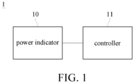
- FIG. 1 is a block diagram illustrating a displayed power correction device according to an embodiment of the present invention.
- the displayed power correction device 1 is adapted to a target battery with a battery temperature lower than a threshold temperature.
- the threshold temperature is -10°C.
- the displayed power correction device 1 includes a power indicator 10 and a controller 11.
- the power indicator 10 is connected to the controller 11.
- the power indicator 10 may be a voltmeter, an ammeter and/or a processor.
- the power indicator 10 is configured to read a gauge of the target battery to obtain designed power of the target battery, meaning the rated capacity of the target battery.
- the designed power may include a designed voltage and a designed current.
- the controller 11 may include one or more processors, said processor is, for example, a central processing unit, a graphics processing unit (GPU), a microcontroller, a programmable logic controller (PLC) or any other processor with signal processing functions.
- the controller 11 is configured to correct displayed power corresponding to the target battery based on the designed power read by the power indicator 10.
- FIG. 2 is a flowchart illustrating a displayed power correction method according to an embodiment of the present invention.
- the displayed power correction method includes: step S101: obtaining the designed power of the target battery; step S103: determining whether the target battery is a first type battery or a second type battery according to the designed power of the target battery; when the determination result of step S103 is "first type battery", performing step S105: determining whether a battery cell voltage is lower than a threshold voltage; when the determination result of step S105 is "yes”, performing step S107: lowering displayed power of the first type battery according to a first default rate; when the determination result of step S105 is "no", performing step S101; when the determination result of step S103 is "second type battery”, performing step S109: determining whether a capacity parameter or a voltage parameter is higher than a default value; when the determination result of step S109 is "
- step S101 the controller 11 receives the designed power of the target battery from the power indicator 10.
- step S103 the controller 11 determines whether the target battery is the first type battery or the second type battery according to the designed power of the target battery.
- the first type battery is a cylindrical battery
- the second type battery is a prismatic battery.
- the controller 11 determines whether the target battery is the first type battery is the first type battery.
- the controller 11 further performs step S105 to determine whether the battery cell voltage of any one of a plurality of battery cells of the target battery is lower than the threshold voltage.
- the threshold voltage is 3 volts.
- the controller 11 determines that the battery cell voltage is lower than the threshold voltage, the controller 11 performs step S107 to lower the displayed power of the target battery according to the first default rate.
- the controller 11 determines that the battery cell voltage is not lower than the threshold voltage, the controller 11 performs step S101 again.
- the controller 11 determines whether the capacity parameter or the voltage parameter is higher than the default value.
- the capacity parameter may be a difference value between a current full charge capacity and a previous full charge capacity.
- the default value corresponding to the capacity parameter may be 150mAh/hour.
- the current full charge capacity may be the full charge capacity of the target battery at the moment, and the previous full charge capacity may be the previously normal full charge capacity of the target battery (for example, the full charge capacity of the target battery when the target battery is sent out of the factory).
- the voltage parameter may be a current voltage of the target battery, and the default value corresponding to the voltage parameter may be a default battery dead voltage.
- step S111 When the controller 11 determines that the capacity parameter or the voltage parameter of the target battery is higher than the corresponding default values, the controller 11 performs step S111 to lower the displayed power of the target battery according to the second default rate. On the contrary, when the controller 11 determines that the capacity parameter and the voltage parameter of the target battery both are not higher than the corresponding default values, the controller 11 performs step S101 again.
- the first default rate may be different from the second default rate. Further, the first default rate may be lower than the second default rate. For example, the first default rate may be lowering the displayed power by 1% every 20 seconds, and the second default rate may be lowering the displayed power by 1% every 15 seconds.
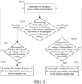
- FIG. 3 is a flowchart illustrating a displayed power correction method according to another embodiment of the present invention.
- the displayed power correction method includes: step S201: obtaining the designed power of the target battery; step S203: determining whether the target battery is the first type battery or the second type battery according to the designed power of the target battery; when the determination result of step S203 is "first type battery", performing step S205: determining whether the battery cell voltage is lower than the threshold voltage; when the determination result of step S205 is "yes”, performing step S207: lowering the displayed power of the first type battery according to the first default rate; when the determination result of step S205 is "no", performing step S201; when the determination result of step S203 is "second type battery", performing step S209: determining whether a current voltage is higher than the default battery dead voltage and an electric capacity of the target battery is unreadable; when the determination result of step S209 is "yes”, performing step S211: lowering the displayed power of
- Steps S201, S203, S205, S207 and S211 of FIG. 3 may be the same as steps S101, S103, S105, S107 and S111 of FIG. 2 , respectively, their descriptions are not repeated herein.
- step S209 the controller 11 determines whether the current voltage of the target battery is higher than the default battery dead voltage and is unable to read the electric capacity of the target battery, wherein the implementation of determining whether the current voltage of the target battery is higher than the default battery dead voltage is described above.
- the controller 11 being unable to read the electric capacity of the target battery may refer to when the target battery does not report battery capacity to the battery voltameter, which causes the controller 11 to be unable to read the electric capacity of the target battery from battery voltameter.
- the controller 11 determines that the current voltage is higher than the default battery dead voltage and the target battery does not report the battery capacity, the controller 11 performs step S211.
- step S211 may be performed when the current voltage is higher than the default battery dead voltage and the electric capacity of the target battery is unreadable.
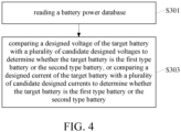
- FIG. 4 is a flowchart illustrating determining battery type according to an embodiment of the present invention.
- FIG. 4 may be regarded as a detailed flowchart of an embodiment of step S103 of FIG. 2 and step S203 of FIG. 3 . As shown in FIG.
- the method of determining battery type includes: step S301: reading a battery power database, wherein the battery power database comprises a candidate designed voltage and a candidate designed current of each of the first type battery and the second type battery; and step S303: comparing the designed voltage of the target battery with the candidate designed voltages to determine whether the target battery is the first type battery or the second type battery, or comparing the designed current of the target battery with the candidate designed currents to determine whether the target battery is the first type battery or the second type battery.
- the designed power of the target battery may include the designed voltage and the designed current.
- the battery power database stores the candidate designed voltage and the candidate designed current of the first type battery and the candidate designed voltage and the candidate designed current of the second type battery.
- the method of storing the candidate designed voltages and the candidate designed currents may be implemented as table 1 below, but the present invention is not limited thereto. Table 1 battery type candidate designed voltage candidate designed current first type battery first candidate designed voltage first candidate designed current second type battery second candidate designed voltage second candidate designed current
- step S301 the controller 11 reads the battery power database.
- step S303 the controller 11 compares the designed voltage of the target battery with the first candidate designed voltage and the second candidate designed voltage. When the comparison result shows that the designed voltage of the target battery is the same as the first candidate designed voltage, the controller 11 may determine that the target battery is the first type battery.
- step S303 the controller 11 compares the designed current of the target battery with the first candidate designed current and the second candidate designed current.
- the controller 11 may determine that the target battery is the first type battery.
- FIG. 5 shows displayed power of not applying the displayed power correction method and device of the present invention
- FIG. 6 shows displayed power of applying the displayed power correction method and device of the present invention.
- the vertical axis in FIG. 5 and FIG. 6 is power (%)
- the horizontal axis in FIG. 5 and FIG. 6 is temperature.
- portion P1 when the displayed power correction method and device of the present invention is not applied and when the ambient temperature lowers to the range of -20°C and -30°C, the power the target battery is displayed abnormally (that is, missing data points).
- the abnormal shut down of the electronic device due to inaccurate displayed power may be avoided.
Landscapes
- Engineering & Computer Science (AREA)
- General Physics & Mathematics (AREA)
- Physics & Mathematics (AREA)
- Theoretical Computer Science (AREA)
- Chemical Kinetics & Catalysis (AREA)
- Electrochemistry (AREA)
- General Chemical & Material Sciences (AREA)
- Chemical & Material Sciences (AREA)
- Manufacturing & Machinery (AREA)
- Quality & Reliability (AREA)
- General Engineering & Computer Science (AREA)
- Power Engineering (AREA)
- Microelectronics & Electronic Packaging (AREA)
- Computing Systems (AREA)
- Charge And Discharge Circuits For Batteries Or The Like (AREA)
- Tests Of Electric Status Of Batteries (AREA)
- Secondary Cells (AREA)
Abstract
Description
- This invention relates to a displayed power correction method and device.
- As personalized electronic devices become more and more popular, these electronic devices have been applied in various fields. For example, the electronic device may be a notebook computer or the like.
- In some more extreme cases, electronic devices may need to operate in extremely low temperature environments. However, in an extremely low temperature environment, the correct power of the electronic device may not be detected due to the influence of temperature, and thus the battery power of the electronic device may not show a linear decrease. Therefore, when an electronic device is used at extremely low temperatures, the displayed battery power may be inaccurate, causing the electronic device to shut down abnormally.
- Accordingly, this invention provides a displayed power correction method and device.
- According to one or more embodiment of this invention, a displayed power correction method, adapted to a target battery with a battery temperature lower than a threshold temperature, is performed by a controller and includes: determining whether the target battery is a first type battery or a second type battery according to designed power of the target battery; lowering displayed power of the first type battery according to a first default rate when the target battery is the first type battery and a battery cell voltage of the target battery is lower than a threshold voltage,; and lowering displayed power of the second type battery according to a second default rate when the target battery is the second type battery and a capacity parameter or a voltage parameter of the target battery is higher than a default value,.
- According to one or more embodiment of this invention, a displayed power correction device, adapted to a target battery with a battery temperature lower than a threshold temperature, includes: a power indicator and a controller. The power indicator is configured to read designed power of the target battery. The controller is connected to the power indicator and configured to perform the displayed power correction method described above.
- In view of the above description, according to one or more embodiments of the displayed power correction method and device of the present invention, even if an electronic device (for example, a laptop) equipped with the target battery is used under extreme low temperature, the abnormal shut down of the electronic device due to inaccurate displayed power may be avoided.
- The present invention will become more fully understood from the detailed description given hereinbelow and the accompanying drawings which are given by way of illustration only and thus are not limitative of the present invention and wherein:
-
FIG. 1 is a block diagram illustrating a displayed power correction device according to an embodiment of the present invention; -
FIG. 2 is a flowchart illustrating a displayed power correction method according to an embodiment of the present invention; -
FIG. 3 is a flowchart illustrating a displayed power correction method according to another embodiment of the present invention; -
FIG. 4 is a flowchart illustrating determining battery type according to an embodiment of the present invention; -
FIG. 5 shows displayed power of not applying the displayed power correction method and device of the present invention; and -
FIG. 6 shows displayed power of applying the displayed power correction method and device of the present invention. - In the following detailed description, for purposes of explanation, numerous specific details are set forth in order to provide a thorough understanding of the disclosed embodiments. According to the description, claims and the drawings disclosed in the specification, one skilled in the art may easily understand the concepts and features of the present invention. The following embodiments further illustrate various aspects of the present invention, but are not meant to limit the scope of the present invention.
- Please refer to
FIG. 1 , whereinFIG. 1 is a block diagram illustrating a displayed power correction device according to an embodiment of the present invention. The displayedpower correction device 1 is adapted to a target battery with a battery temperature lower than a threshold temperature. For example, the threshold temperature is -10°C. A shown inFIG. 1 , the displayedpower correction device 1 includes apower indicator 10 and acontroller 11. Thepower indicator 10 is connected to thecontroller 11. - The
power indicator 10 may be a voltmeter, an ammeter and/or a processor. Thepower indicator 10 is configured to read a gauge of the target battery to obtain designed power of the target battery, meaning the rated capacity of the target battery. For example, the designed power may include a designed voltage and a designed current. Thecontroller 11 may include one or more processors, said processor is, for example, a central processing unit, a graphics processing unit (GPU), a microcontroller, a programmable logic controller (PLC) or any other processor with signal processing functions. Thecontroller 11 is configured to correct displayed power corresponding to the target battery based on the designed power read by thepower indicator 10. - To explain the displayed
power correction device 1 and the displayed power correction method in more detail, please refer toFIG. 1 andFIG. 2 , whereinFIG. 2 is a flowchart illustrating a displayed power correction method according to an embodiment of the present invention. As shown inFIG. 2 , the displayed power correction method includes: step S101: obtaining the designed power of the target battery; step S103: determining whether the target battery is a first type battery or a second type battery according to the designed power of the target battery; when the determination result of step S103 is "first type battery", performing step S105: determining whether a battery cell voltage is lower than a threshold voltage; when the determination result of step S105 is "yes", performing step S107: lowering displayed power of the first type battery according to a first default rate; when the determination result of step S105 is "no", performing step S101; when the determination result of step S103 is "second type battery", performing step S109: determining whether a capacity parameter or a voltage parameter is higher than a default value; when the determination result of step S109 is "yes", performing step S111: lowering displayed power of the second type battery according to a second default rate; and when the determination result of step S109 is "no", performing step S101. - In step S101, the
controller 11 receives the designed power of the target battery from thepower indicator 10. In step S103, thecontroller 11 determines whether the target battery is the first type battery or the second type battery according to the designed power of the target battery. For example, the first type battery is a cylindrical battery, and the second type battery is a prismatic battery. - When the
controller 11 determines that the target battery is the first type battery, thecontroller 11 further performs step S105 to determine whether the battery cell voltage of any one of a plurality of battery cells of the target battery is lower than the threshold voltage. For example, the threshold voltage is 3 volts. When thecontroller 11 determines that the battery cell voltage is lower than the threshold voltage, thecontroller 11 performs step S107 to lower the displayed power of the target battery according to the first default rate. On the contrary, when thecontroller 11 determines that the battery cell voltage is not lower than the threshold voltage, thecontroller 11 performs step S101 again. - When the
controller 11 determines that the target battery is the second type battery, thecontroller 11 further performs step S109 to determine whether the capacity parameter or the voltage parameter is higher than the default value. The capacity parameter may be a difference value between a current full charge capacity and a previous full charge capacity. The default value corresponding to the capacity parameter may be 150mAh/hour. The current full charge capacity may be the full charge capacity of the target battery at the moment, and the previous full charge capacity may be the previously normal full charge capacity of the target battery (for example, the full charge capacity of the target battery when the target battery is sent out of the factory). The voltage parameter may be a current voltage of the target battery, and the default value corresponding to the voltage parameter may be a default battery dead voltage. - When the
controller 11 determines that the capacity parameter or the voltage parameter of the target battery is higher than the corresponding default values, thecontroller 11 performs step S111 to lower the displayed power of the target battery according to the second default rate. On the contrary, when thecontroller 11 determines that the capacity parameter and the voltage parameter of the target battery both are not higher than the corresponding default values, thecontroller 11 performs step S101 again. - In an embodiment, the first default rate may be different from the second default rate. Further, the first default rate may be lower than the second default rate. For example, the first default rate may be lowering the displayed power by 1% every 20 seconds, and the second default rate may be lowering the displayed power by 1% every 15 seconds.
- Accordingly, even if an electronic device (for example, a laptop) equipped with the target battery is used under extreme low temperature, the abnormal shut down of the electronic device due to inaccurate displayed power may be avoided.
- Please refer to
FIG. 1 andFIG. 3 , whereinFIG. 3 is a flowchart illustrating a displayed power correction method according to another embodiment of the present invention. As shown inFIG. 3 , the displayed power correction method includes: step S201: obtaining the designed power of the target battery; step S203: determining whether the target battery is the first type battery or the second type battery according to the designed power of the target battery; when the determination result of step S203 is "first type battery", performing step S205: determining whether the battery cell voltage is lower than the threshold voltage; when the determination result of step S205 is "yes", performing step S207: lowering the displayed power of the first type battery according to the first default rate; when the determination result of step S205 is "no", performing step S201; when the determination result of step S203 is "second type battery", performing step S209: determining whether a current voltage is higher than the default battery dead voltage and an electric capacity of the target battery is unreadable; when the determination result of step S209 is "yes", performing step S211: lowering the displayed power of the second type battery according to the second default rate; and when the determination result of step S209 is "no", performing step S201. - Steps S201, S203, S205, S207 and S211 of
FIG. 3 may be the same as steps S101, S103, S105, S107 and S111 ofFIG. 2 , respectively, their descriptions are not repeated herein. - In step S209, the
controller 11 determines whether the current voltage of the target battery is higher than the default battery dead voltage and is unable to read the electric capacity of the target battery, wherein the implementation of determining whether the current voltage of the target battery is higher than the default battery dead voltage is described above. - The
controller 11 being unable to read the electric capacity of the target battery may refer to when the target battery does not report battery capacity to the battery voltameter, which causes thecontroller 11 to be unable to read the electric capacity of the target battery from battery voltameter. When thecontroller 11 determines that the current voltage is higher than the default battery dead voltage and the target battery does not report the battery capacity, thecontroller 11 performs step S211. In other words, step S211 may be performed when the current voltage is higher than the default battery dead voltage and the electric capacity of the target battery is unreadable. - Please refer to
FIG. 1 andFIG. 4 , whereinFIG. 4 is a flowchart illustrating determining battery type according to an embodiment of the present invention.FIG. 4 may be regarded as a detailed flowchart of an embodiment of step S103 ofFIG. 2 and step S203 ofFIG. 3 . As shown inFIG. 4 , the method of determining battery type includes: step S301: reading a battery power database, wherein the battery power database comprises a candidate designed voltage and a candidate designed current of each of the first type battery and the second type battery; and step S303: comparing the designed voltage of the target battery with the candidate designed voltages to determine whether the target battery is the first type battery or the second type battery, or comparing the designed current of the target battery with the candidate designed currents to determine whether the target battery is the first type battery or the second type battery. - As described above, the designed power of the target battery may include the designed voltage and the designed current. The battery power database stores the candidate designed voltage and the candidate designed current of the first type battery and the candidate designed voltage and the candidate designed current of the second type battery. For example, the method of storing the candidate designed voltages and the candidate designed currents may be implemented as table 1 below, but the present invention is not limited thereto.
Table 1 battery type candidate designed voltage candidate designed current first type battery first candidate designed voltage first candidate designed current second type battery second candidate designed voltage second candidate designed current - In step S301, the
controller 11 reads the battery power database. In step S303, thecontroller 11 compares the designed voltage of the target battery with the first candidate designed voltage and the second candidate designed voltage. When the comparison result shows that the designed voltage of the target battery is the same as the first candidate designed voltage, thecontroller 11 may determine that the target battery is the first type battery. - Or, in step S303, the
controller 11 compares the designed current of the target battery with the first candidate designed current and the second candidate designed current. When the comparison result shows that the designed current of the target battery is the same as the first candidate designed current, thecontroller 11 may determine that the target battery is the first type battery. - Please refer to
FIG. 5 and FIG. 6 , whereinFIG. 5 shows displayed power of not applying the displayed power correction method and device of the present invention, andFIG. 6 shows displayed power of applying the displayed power correction method and device of the present invention. The vertical axis inFIG. 5 and FIG. 6 is power (%), and the horizontal axis inFIG. 5 and FIG. 6 is temperature. - In
FIG. 5 , as shown by portion P1, when the displayed power correction method and device of the present invention is not applied and when the ambient temperature lowers to the range of -20°C and -30°C, the power the target battery is displayed abnormally (that is, missing data points). - In
FIG. 6 , as shown by portion P2, when the displayed power correction method and device of the present invention is applied, even if the ambient temperature lowers to the range of -30°C and -40°C, the power the target battery is still displayed normally (that is, no data point is missing). Therefore, the abnormal shut down of the electronic device due to inaccurate displayed power may be avoided - In view of the above description, according to one or more embodiments of the displayed power correction method and device of the present invention, even if an electronic device (for example, a laptop) equipped with the target battery is used under extreme low temperature, the abnormal shut down of the electronic device due to inaccurate displayed power may be avoided.
Claims (10)
- A displayed power correction method, adapted to a target battery with a battery temperature lower than a threshold temperature, performed by a controller (11) and comprising:determining (S103,S203) whether the target battery is a first type battery or a second type battery according to designed power of the target battery;lowering (S107,S207) displayed power of the first type battery according to a first default rate when the target battery is the first type battery and a battery cell voltage of the target battery is lower than a threshold voltage; andlowering (S111,S211) displayed power of the second type battery according to a second default rate when the target battery is the second type battery and a capacity parameter or a voltage parameter of the target battery is higher than a default value.
- The displayed power correction method according to claim 1, wherein the first type battery is a cylindrical battery, and the second type battery is a prismatic battery.
- The displayed power correction method according to claim 1, wherein the capacity parameter is a difference value between a current full charge capacity and a previous full charge capacity.
- The displayed power correction method according to claim 3, wherein the default value corresponding to the capacity parameter is 150mAh/hour.
- The displayed power correction method according to claim 1, wherein the voltage parameter is a current voltage, the default value is a default battery dead voltage, and lowering the displayed power of the second type battery according to the second default rate is performed when the current voltage is higher than the default battery dead voltage and electric capacity of the target battery is unreadable.
- The displayed power correction method according to claim 1, wherein the first default rate is lower than the second default rate.
- The displayed power correction method according to claim 1, wherein the designed power comprises a designed voltage and a designed current.
- The displayed power correction method according to claim 7, wherein determining whether the target battery is the first type battery or the second type battery according to the designed power of the target battery comprises:reading (S301) a battery power database, wherein the battery power database comprises a candidate designed voltage and a candidate designed current of each of the first type battery and the second type battery; andcomparing (S303) the designed voltage of the target battery with the candidate designed voltages to determine whether the target battery is the first type battery or the second type battery, or comparing the designed current of the target battery with the candidate designed currents to determine whether the target battery is the first type battery or the second type battery.
- The displayed power correction method according to claim 8, wherein the battery cell voltage is a voltage of any one of a plurality battery cells of the target battery.
- A displayed power correction device (1), adapted to a target battery with a battery temperature lower than a threshold temperature, comprising:a power indicator (10) configured to read designed power of the target battery; anda controller (11) connected to the power indicator (10), the controller (11) configured to perform the displayed power correction method according to any one of claims 1-9.
Applications Claiming Priority (1)
| Application Number | Priority Date | Filing Date | Title |
|---|---|---|---|
| CN202311616134.1A CN120066884A (en) | 2023-11-28 | 2023-11-28 | Display electric quantity correction method and device |
Publications (2)
| Publication Number | Publication Date |
|---|---|
| EP4564033A1 true EP4564033A1 (en) | 2025-06-04 |
| EP4564033B1 EP4564033B1 (en) | 2026-03-25 |
Family
ID=93258893
Family Applications (1)
| Application Number | Title | Priority Date | Filing Date |
|---|---|---|---|
| EP24208346.7A Active EP4564033B1 (en) | 2023-11-28 | 2024-10-23 | Displayed power correction method and device |
Country Status (3)
| Country | Link |
|---|---|
| US (1) | US20250172619A1 (en) |
| EP (1) | EP4564033B1 (en) |
| CN (1) | CN120066884A (en) |
Citations (2)
| Publication number | Priority date | Publication date | Assignee | Title |
|---|---|---|---|---|
| US5912544A (en) * | 1995-06-22 | 1999-06-15 | Hitachi Denshi Kabushiki Kaisha | Electronic equipment and method for enabling plural types of batteries to be selectively used |
| US20230093677A1 (en) * | 2021-09-22 | 2023-03-23 | Apple Inc. | Battery power capability prediction and correction |
-
2023
- 2023-11-28 CN CN202311616134.1A patent/CN120066884A/en active Pending
-
2024
- 2024-06-03 US US18/731,479 patent/US20250172619A1/en active Pending
- 2024-10-23 EP EP24208346.7A patent/EP4564033B1/en active Active
Patent Citations (2)
| Publication number | Priority date | Publication date | Assignee | Title |
|---|---|---|---|---|
| US5912544A (en) * | 1995-06-22 | 1999-06-15 | Hitachi Denshi Kabushiki Kaisha | Electronic equipment and method for enabling plural types of batteries to be selectively used |
| US20230093677A1 (en) * | 2021-09-22 | 2023-03-23 | Apple Inc. | Battery power capability prediction and correction |
Also Published As
| Publication number | Publication date |
|---|---|
| EP4564033B1 (en) | 2026-03-25 |
| CN120066884A (en) | 2025-05-30 |
| US20250172619A1 (en) | 2025-05-29 |
Similar Documents
| Publication | Publication Date | Title |
|---|---|---|
| US20200326379A1 (en) | Electronic device and method for detecting the state of health of a battery | |
| US6483274B2 (en) | Device and method for displaying charge capacity information of smart battery | |
| US11682346B2 (en) | Method, apparatus, and device for determining aging degree of pixel in display panel, and method, apparatus, and device for compensating display brightness of pixel | |
| US10545185B2 (en) | Apparatus and method for diagnosing current sensor | |
| US6518730B2 (en) | Power supply unit, battery electrical apparatus, and memory effect detection method | |
| EP4446764A1 (en) | Battery state management device and operation method thereof | |
| US20200366117A1 (en) | Control device for lithium ion secondary battery and control method thereof | |
| US8988046B2 (en) | Electronic device using rechargeable batteries and battery status control method applicable thereto | |
| US11811029B2 (en) | Charging method and battery pack | |
| US20240175937A1 (en) | Battery management apparatus and method | |
| EP4564033A1 (en) | Displayed power correction method and device | |
| US11280843B2 (en) | Method of determining an aging level of a battery | |
| CN103426478A (en) | Read circuit of flash memory | |
| KR20220124598A (en) | Smart battery device and its operation method | |
| US11593479B1 (en) | Systems and methods for detecting an attack on a battery management system | |
| CN116840703A (en) | Method, system and equipment for identifying battery self-discharge abnormality | |
| CN113740782B (en) | Wiring detection method | |
| US20190187737A1 (en) | Semiconductor device, sensor terminal, and semiconductor device control method | |
| CN111312167B (en) | Voltage output method, device, controller and storage medium | |
| CN118098119B (en) | Driving method and driving circuit of display panel and display device | |
| TWI857871B (en) | Displayed power correction method and device | |
| CN116710791A (en) | Battery management device and method | |
| WO2022092109A1 (en) | Power storage device, charging method, and program | |
| CN106991028B (en) | Method and system for processing temperature abnormity of computer | |
| JP2020092473A (en) | Battery control system, battery device, computer device, battery control method and program |
Legal Events
| Date | Code | Title | Description |
|---|---|---|---|
| PUAI | Public reference made under article 153(3) epc to a published international application that has entered the european phase |
Free format text: ORIGINAL CODE: 0009012 |
|
| STAA | Information on the status of an ep patent application or granted ep patent |
Free format text: STATUS: THE APPLICATION HAS BEEN PUBLISHED |
|
| AK | Designated contracting states |
Kind code of ref document: A1 Designated state(s): AL AT BE BG CH CY CZ DE DK EE ES FI FR GB GR HR HU IE IS IT LI LT LU LV MC ME MK MT NL NO PL PT RO RS SE SI SK SM TR |
|
| STAA | Information on the status of an ep patent application or granted ep patent |
Free format text: STATUS: REQUEST FOR EXAMINATION WAS MADE |
|
| 17P | Request for examination filed |
Effective date: 20250807 |
|
| GRAP | Despatch of communication of intention to grant a patent |
Free format text: ORIGINAL CODE: EPIDOSNIGR1 |
|
| STAA | Information on the status of an ep patent application or granted ep patent |
Free format text: STATUS: GRANT OF PATENT IS INTENDED |
|
| INTG | Intention to grant announced |
Effective date: 20251223 |
|
| RIC1 | Information provided on ipc code assigned before grant |
Ipc: G01R 31/374 20190101AFI20251212BHEP Ipc: H02J 7/00 20060101ALI20251212BHEP Ipc: H01M 10/42 20060101ALI20251212BHEP Ipc: H01M 10/48 20060101ALI20251212BHEP |
|
| GRAS | Grant fee paid |
Free format text: ORIGINAL CODE: EPIDOSNIGR3 |
|
| GRAA | (expected) grant |
Free format text: ORIGINAL CODE: 0009210 |
|
| STAA | Information on the status of an ep patent application or granted ep patent |
Free format text: STATUS: THE PATENT HAS BEEN GRANTED |
|
| AK | Designated contracting states |
Kind code of ref document: B1 Designated state(s): AL AT BE BG CH CY CZ DE DK EE ES FI FR GB GR HR HU IE IS IT LI LT LU LV MC ME MK MT NL NO PL PT RO RS SE SI SK SM TR |
|
| REG | Reference to a national code |
Ref country code: CH Ref legal event code: F10 Free format text: ST27 STATUS EVENT CODE: U-0-0-F10-F00 (AS PROVIDED BY THE NATIONAL OFFICE) Effective date: 20260325 Ref country code: GB Ref legal event code: FG4D |
|
| REG | Reference to a national code |
Ref country code: DE Ref legal event code: R096 Ref document number: 602024003438 Country of ref document: DE |
|
| REG | Reference to a national code |
Ref country code: IE Ref legal event code: FG4D |