EP4564010A1 - Dispensing device, mixing device, and analysis device - Google Patents
Dispensing device, mixing device, and analysis device Download PDFInfo
- Publication number
- EP4564010A1 EP4564010A1 EP23846242.8A EP23846242A EP4564010A1 EP 4564010 A1 EP4564010 A1 EP 4564010A1 EP 23846242 A EP23846242 A EP 23846242A EP 4564010 A1 EP4564010 A1 EP 4564010A1
- Authority
- EP
- European Patent Office
- Prior art keywords
- sample
- flow passage
- mixing
- dispensing
- pressing
- Prior art date
- Legal status (The legal status is an assumption and is not a legal conclusion. Google has not performed a legal analysis and makes no representation as to the accuracy of the status listed.)
- Pending
Links
Images








Classifications
-
- G—PHYSICS
- G01—MEASURING; TESTING
- G01N—INVESTIGATING OR ANALYSING MATERIALS BY DETERMINING THEIR CHEMICAL OR PHYSICAL PROPERTIES
- G01N1/00—Sampling; Preparing specimens for investigation
- G01N1/28—Preparing specimens for investigation including physical details of (bio-)chemical methods covered elsewhere, e.g. G01N33/50, C12Q
- G01N1/38—Diluting, dispersing or mixing samples
-
- B—PERFORMING OPERATIONS; TRANSPORTING
- B01—PHYSICAL OR CHEMICAL PROCESSES OR APPARATUS IN GENERAL
- B01F—MIXING, e.g. DISSOLVING, EMULSIFYING OR DISPERSING
- B01F25/00—Flow mixers; Mixers for falling materials, e.g. solid particles
- B01F25/40—Static mixers
- B01F25/42—Static mixers in which the mixing is affected by moving the components jointly in changing directions, e.g. in tubes provided with baffles or obstructions
- B01F25/43—Mixing tubes, e.g. wherein the material is moved in a radial or partly reversed direction
- B01F25/431—Straight mixing tubes with baffles or obstructions that do not cause substantial pressure drop; Baffles therefor
- B01F25/43197—Straight mixing tubes with baffles or obstructions that do not cause substantial pressure drop; Baffles therefor characterised by the mounting of the baffles or obstructions
- B01F25/431971—Mounted on the wall
-
- B—PERFORMING OPERATIONS; TRANSPORTING
- B01—PHYSICAL OR CHEMICAL PROCESSES OR APPARATUS IN GENERAL
- B01L—CHEMICAL OR PHYSICAL LABORATORY APPARATUS FOR GENERAL USE
- B01L3/00—Containers or dishes for laboratory use, e.g. laboratory glassware; Droppers
- B01L3/50—Containers for the purpose of retaining a material to be analysed, e.g. test tubes
- B01L3/502—Containers for the purpose of retaining a material to be analysed, e.g. test tubes with fluid transport, e.g. in multi-compartment structures
- B01L3/5027—Containers for the purpose of retaining a material to be analysed, e.g. test tubes with fluid transport, e.g. in multi-compartment structures by integrated microfluidic structures, i.e. dimensions of channels and chambers are such that surface tension forces are important, e.g. lab-on-a-chip
- B01L3/50273—Containers for the purpose of retaining a material to be analysed, e.g. test tubes with fluid transport, e.g. in multi-compartment structures by integrated microfluidic structures, i.e. dimensions of channels and chambers are such that surface tension forces are important, e.g. lab-on-a-chip characterised by the means or forces applied to move the fluids
-
- G—PHYSICS
- G01—MEASURING; TESTING
- G01N—INVESTIGATING OR ANALYSING MATERIALS BY DETERMINING THEIR CHEMICAL OR PHYSICAL PROPERTIES
- G01N35/00—Automatic analysis not limited to methods or materials provided for in any single one of groups G01N1/00 - G01N33/00; Handling materials therefor
- G01N35/08—Automatic analysis not limited to methods or materials provided for in any single one of groups G01N1/00 - G01N33/00; Handling materials therefor using a stream of discrete samples flowing along a tube system, e.g. flow injection analysis
-
- G—PHYSICS
- G01—MEASURING; TESTING
- G01N—INVESTIGATING OR ANALYSING MATERIALS BY DETERMINING THEIR CHEMICAL OR PHYSICAL PROPERTIES
- G01N35/00—Automatic analysis not limited to methods or materials provided for in any single one of groups G01N1/00 - G01N33/00; Handling materials therefor
- G01N35/10—Devices for transferring samples or any liquids to, in, or from, the analysis apparatus, e.g. suction devices, injection devices
-
- B—PERFORMING OPERATIONS; TRANSPORTING
- B01—PHYSICAL OR CHEMICAL PROCESSES OR APPARATUS IN GENERAL
- B01L—CHEMICAL OR PHYSICAL LABORATORY APPARATUS FOR GENERAL USE
- B01L2200/00—Solutions for specific problems relating to chemical or physical laboratory apparatus
- B01L2200/06—Fluid handling related problems
- B01L2200/0605—Metering of fluids
-
- B—PERFORMING OPERATIONS; TRANSPORTING
- B01—PHYSICAL OR CHEMICAL PROCESSES OR APPARATUS IN GENERAL
- B01L—CHEMICAL OR PHYSICAL LABORATORY APPARATUS FOR GENERAL USE
- B01L2200/00—Solutions for specific problems relating to chemical or physical laboratory apparatus
- B01L2200/06—Fluid handling related problems
- B01L2200/0673—Handling of plugs of fluid surrounded by immiscible fluid
-
- B—PERFORMING OPERATIONS; TRANSPORTING
- B01—PHYSICAL OR CHEMICAL PROCESSES OR APPARATUS IN GENERAL
- B01L—CHEMICAL OR PHYSICAL LABORATORY APPARATUS FOR GENERAL USE
- B01L2300/00—Additional constructional details
- B01L2300/08—Geometry, shape and general structure
- B01L2300/0861—Configuration of multiple channels and/or chambers in a single devices
- B01L2300/0867—Multiple inlets and one sample wells, e.g. mixing, dilution
-
- B—PERFORMING OPERATIONS; TRANSPORTING
- B01—PHYSICAL OR CHEMICAL PROCESSES OR APPARATUS IN GENERAL
- B01L—CHEMICAL OR PHYSICAL LABORATORY APPARATUS FOR GENERAL USE
- B01L2300/00—Additional constructional details
- B01L2300/14—Means for pressure control
-
- B—PERFORMING OPERATIONS; TRANSPORTING
- B01—PHYSICAL OR CHEMICAL PROCESSES OR APPARATUS IN GENERAL
- B01L—CHEMICAL OR PHYSICAL LABORATORY APPARATUS FOR GENERAL USE
- B01L2400/00—Moving or stopping fluids
- B01L2400/04—Moving fluids with specific forces or mechanical means
- B01L2400/0403—Moving fluids with specific forces or mechanical means specific forces
- B01L2400/043—Moving fluids with specific forces or mechanical means specific forces magnetic forces
-
- B—PERFORMING OPERATIONS; TRANSPORTING
- B01—PHYSICAL OR CHEMICAL PROCESSES OR APPARATUS IN GENERAL
- B01L—CHEMICAL OR PHYSICAL LABORATORY APPARATUS FOR GENERAL USE
- B01L2400/00—Moving or stopping fluids
- B01L2400/04—Moving fluids with specific forces or mechanical means
- B01L2400/0475—Moving fluids with specific forces or mechanical means specific mechanical means and fluid pressure
- B01L2400/0481—Moving fluids with specific forces or mechanical means specific mechanical means and fluid pressure squeezing of channels or chambers
-
- G—PHYSICS
- G01—MEASURING; TESTING
- G01N—INVESTIGATING OR ANALYSING MATERIALS BY DETERMINING THEIR CHEMICAL OR PHYSICAL PROPERTIES
- G01N35/00—Automatic analysis not limited to methods or materials provided for in any single one of groups G01N1/00 - G01N33/00; Handling materials therefor
- G01N35/10—Devices for transferring samples or any liquids to, in, or from, the analysis apparatus, e.g. suction devices, injection devices
- G01N2035/1027—General features of the devices
- G01N2035/1048—General features of the devices using the transfer device for another function
- G01N2035/1058—General features of the devices using the transfer device for another function for mixing
-
- G—PHYSICS
- G01—MEASURING; TESTING
- G01N—INVESTIGATING OR ANALYSING MATERIALS BY DETERMINING THEIR CHEMICAL OR PHYSICAL PROPERTIES
- G01N35/00—Automatic analysis not limited to methods or materials provided for in any single one of groups G01N1/00 - G01N33/00; Handling materials therefor
- G01N35/10—Devices for transferring samples or any liquids to, in, or from, the analysis apparatus, e.g. suction devices, injection devices
- G01N2035/1027—General features of the devices
- G01N2035/1048—General features of the devices using the transfer device for another function
- G01N2035/1062—General features of the devices using the transfer device for another function for testing the liquid while it is in the transfer device
Definitions
- the present invention relates to a dispensing device for dispensing a liquid sample, a mixing device, and an analysis device.
- Patent Document 1 Conventionally, as a technique for dispensing a sample, a dispensing device of Patent Document 1 is disclosed.
- the dispensing device of Patent Document 1 employs a configuration including one ceramic heater that heats a part of a washing fluid filling a flow passage to generate a gas bubble and another ceramic heater that heats a washing fluid at a position closer to a syringe piston pump side than the heating position of the one ceramic heater to generate another gas bubble in a state where a layer of the washing fluid is interposed between the gas bubble and the other gas bubble.
- Patent Document 1 JP-A-2005-3610
- the present invention has been made in consideration of the above-described circumstances, and it is an object of the present invention to provide a technique capable of improving the dispensing accuracy of a liquid sample.
- a dispensing device is a dispensing device for dispensing a liquid sample that includes a cylindrical first flow passage, a pressing portion, and a press control unit.
- the first flow passage is provided with a cylindrical main body portion, an opening portion formed at the main body portion, and a lid portion that closes the opening portion and has higher flexibility than the main body portion.
- a liquid first sample flows down the first flow passage.
- the pressing portion is for pressing the lid portion.
- the press control unit controls the pressing of the pressing portion against the lid portion.
- the first flow passage is provided with a sample injection port formed at an upstream side with respect to the lid portion, and an injection portion for injecting a gas between the sample injection port and the lid portion.
- a mixing device is a mixing device that includes the dispensing device of the present invention and mixes the first sample and a second sample.
- the mixing device includes a second flow passage connected to the first flow passage at a downstream side with respect to the lid portion, a cylindrical third flow passage for making the second sample flow down, a joining portion at which the second flow passage joins the third flow passage, and a mixing flow passage for generating a mixed sample in which the first sample and the second sample are mixed at a downstream side with respect to the joining portion.
- At least any of the first sample and the second sample contains a magnetic insulator, and the mixing flow passage internally includes an electromagnet.
- An analysis device is an analysis device that includes the mixing device of the present invention and analyzes the mixed sample.
- the analysis device includes an irradiation unit that irradiates the mixed sample adhered to the electromagnet with a light, a measurement unit that measures a reflected light of the light emitted by the irradiation unit, and a quantitative determination unit that determines a quantity of the mixed sample based on a result of the measurement by the measurement unit.
- the present invention can provide the technique capable of improving the dispensing accuracy of a liquid sample.
- Fig. 1 is a schematic diagram illustrating an example of an analysis device 100 of a first embodiment.
- the analysis device 100 includes a dispensing device 1, a mixing device 2, an information processing device 4, an imaging device 51, an irradiation unit 52, and a measurement unit 53.
- the analysis device 100 analyzes a sample, such as a liquid specimen.
- Fig. 2 is a diagram illustrating an example of the dispensing device 1 of the first embodiment. As illustrated in Fig. 2 , the dispensing device 1 dispenses a liquid sample 7. The dispensing device 1 is provided with a first flow passage 11, a pressing portion 12, and a press control unit 13.
- the first flow passage 11 the liquid sample 7 flows down.
- the first flow passage 11 is provided with a sample injection port 11a at an upstream side in a flow-down direction of the sample 7.
- the sample injection port 11a is, for example, provided with a sample injection device (not illustrated), and the sample injection device can inject the sample 7 into the first flow passage 11.
- the sample injection device is connected to the information processing device 4, and an injection timing, a flow-down speed, a flow-down amount, and the like of the sample 7 injected into the first flow passage 11 can be controlled by a processing unit 49 of the information processing device 4.
- the first flow passage 11 is provided with a cylindrical main body portion 14, an opening portion 15 formed at a sidewall of the main body portion 14, and a lid portion 16 that closes the opening portion 15 and has higher flexibility than the main body portion 14.
- the material of the main body portion 14 is, for example, glass.
- the opening portion 15 is an opening formed in a circular shape, a rectangular shape, or the like at a part of the sidewall of the main body portion 14.
- the material of the lid portion 16 is, for example, soft plastic, such as polyethylene, having higher flexibility than the main body portion 14.
- the inner surface of the lid portion 16 is preferably formed to be flush with the inner surface of the main body portion 14.
- the pressing portion 12 presses the lid portion 16 from the outside of the first flow passage 11. By pressing the lid portion 16 by the pressing portion 12, the lid portion 16 can be bent toward the inside of the first flow passage 11.
- the pressing portion 12 includes a plurality of blade portions 18 rotatable around a rotation shaft 17.
- the press control unit 13 controls the pressing of the pressing portion 12 against the lid portion 16.
- a motor that rotates the rotation shaft 17 of the pressing portion 12 at constant speed is used for the press control unit 13.
- the control of the pressing of the pressing portion 12 by the press control unit 13 can be controlled by the processing unit 49 of the information processing device 4.
- the first flow passage 11 is provided with an injection portion 19 for injecting a gas, such as air, between the sample injection port 11a and the lid portion 16 at the sidewall.
- a gas such as air
- the injection portion 19 is, for example, provided with a gas injection device (not illustrated), and the gas injection device can inject the gas into the first flow passage 11.
- the gas injection device is connected to the information processing device 4, and an injection timing, an injection amount, and the like of the gas injected into the first flow passage 11 can be controlled by, for example, the processing unit 49 of the information processing device 4.
- the first flow passage 11 is connected to the mixing device 2 at a downstream side with respect to the lid portion 16.
- the sample 7 is continuously injected into the first flow passage 11 from the sample injection port 11a.
- a predetermined amount of an air S is injected from the injection portion 19.
- the sample 7 injected into the first flow passage 11 is divided into a sample 7a at a downstream side and a sample 7b at an upstream side with respect to the injection portion 19 by the air S.
- a sample 7c remains in the air S between the sample 7a at the downstream side and the sample 7b at the upstream side with respect to the injection portion 19 in some cases. In this case, the dispensing accuracy of the sample 7a at the downstream side with respect to the injection portion 19 is reduced by the amount of the sample 7c remaining in the air S.
- the lid portion 16 is pressed by the pressing portion 12.
- the press control unit 13 rotates the rotation shaft 17, thereby pressing the lid portion 16 with the blade portion 18 provided at the rotation shaft 17. This allows the lid portion 16 to be bent to the inside of the first flow passage 11. Bending the lid portion 16 causes the sample 7c remaining in the air S to be extruded to the downstream side and integrated with the sample 7a at the downstream side. Therefore, the dispensing accuracy of the sample 7a at the downstream side can be improved.
- the press control unit 13 further rotates the rotation shaft 17 to separate the blade portion 18 provided at the rotation shaft 17 from the lid portion 16.
- the dispensing device 1 can sequentially dispense the sample 7.
- the pressing portion 12 for pressing the lid portion 16 and the press control unit 13 that controls the pressing of the pressing portion 12 against the lid portion 16 are provided. This allows the pressing portion 12 to bend the lid portion 16 to the inside of the first flow passage 11 when the air S flows down the lid portion 16. Therefore, the sample 7c remaining in the air S is extruded to the downstream side and integrated with the sample 7a at the downstream side. Accordingly, the dispensing accuracy of the sample 7 can be improved.
- the pressing portion 12 is provided with the plurality of blade portions 18 rotatable around the rotation shaft 17, and the press control unit 13 rotates the rotation shaft 17. This allows facilitating control of the pressing timing of the blade portion 18 against the lid portion 16. Therefore, the sample 7 can be dispensed with high efficiency.
- the inner surface of the lid portion 16 is flush with the inner surface of the main body portion 14. This allows the sample 7 to smoothly flow down inside the first flow passage 11 even after the air S is injected into the first flow passage 11 by the injection portion 19. Therefore, the sample 7c remaining in the air S is less likely to remain in the first flow passage 11. Consequently, by bending the lid portion 16, the sample 7c remaining in the air S is smoothly extruded to the downstream side and integrated with the sample 7a at the downstream side. Therefore, the dispensing accuracy of the sample 7 can be further improved.
- Fig. 5 is diagrams illustrating the dispensing device 1 of the first modification.
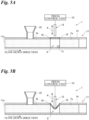
- the press control unit 13 allows the pressing portion 12 to move in directions intersecting with the flow-down direction of the sample 7 (directions of an arrow A in the diagram). This allows the pressing portion 12 to bend the lid portion 16 to the inside of the first flow passage 11 when the air S flows down the lid portion 16. Therefore, as illustrated in Fig. 5B , the sample 7c remaining in the air S is extruded to the downstream side and integrated with the sample 7a at the downstream side.
- the press control unit 13 allows the pressing portion 12 to move in the directions intersecting with the flow-down direction of the sample 7. This allows easily bending the lid portion 16 to the inside of the first flow passage 11 when the pressing portion 12 presses the lid portion 16.
- the sample 7c remaining in the air S is extruded to the downstream side and integrated with the sample 7a at the downstream side. Therefore, the dispensing accuracy of the sample 7a at the downstream side can be improved.
- Fig. 6 is a diagram illustrating the dispensing device 1 of the second modification.
- a plurality of the first flow passages 11 are provided, and one pressing portion 12 can simultaneously press the lid portions 16 provided at the respective first flow passages 11.
- the one pressing portion 12 is provided across a plurality of the lid portions 16, and can simultaneously press the plurality of lid portions 16.
- the pressing portion 12 allows, for example, the pressing portion 12 to move in directions intersecting with the flow-down direction of the sample 7 (a near side direction and a far side direction of the paper surface of Fig. 6 ).
- the plurality of first flow passages 11 are provided, and one pressing portion 12 can simultaneously press the plurality of lid portions 16. This allows simultaneously dispensing the sample 7 flowing down the plurality of first flow passages 11. Therefore, the sample 7 can be dispensed with high efficiency.
- Fig. 7 is a diagram illustrating an example of the mixing device 2 of the first embodiment.
- the mixing device 2 includes the dispensing device 1, and mixes the liquid sample 7 and a liquid sample 8.
- the mixing device 2 is connected to the first flow passage 11 of the dispensing device 1.
- the mixing device 2 is provided with a second flow passage 22, a third flow passage 23, a fourth flow passage 24, a joining portion 26, and a mixing flow passage 27.
- the fourth flow passage 24 may be omitted.
- a direction toward the mixing flow passage 27 is defined as the flow-down direction.
- the second flow passage 22 is connected to the first flow passage 11 of the dispensing device 1 at the downstream side with respect to the lid portion 16.
- the second flow passage 22 may be integrally formed with the first flow passage 11.
- the second flow passage 22 may be formed separately from the first flow passage 11 and connected via a connecting pipe that connects the first flow passage 11 to the second flow passage 22.
- a plurality of the second flow passages 22 may be provided.
- the third flow passage 23 the sample 8 different from the sample 7 flows down.
- the third flow passage 23 is formed in a cylindrical shape.
- the third flow passage 23 is transparent.
- the third flow passage 23 is provided with a sample injection port 23a to inject the sample 8.
- the sample injection port 23a is, for example, provided with a sample injection device (not illustrated), and the sample injection device can inject the sample into the third flow passage 23.
- the sample injection device is connected to the information processing device 4, and an injection timing, a flow-down speed, a flow-down amount, and the like of the sample injected into the third flow passage 23 can be controlled by, for example, the processing unit 49 of the information processing device 4.
- the third flow passage 23 is provided with an injection portion 29 for injecting a gas, such as air, at a sidewall at the downstream side with respect to the sample injection port 23a.
- a gas such as air
- the injection portion 29 is, for example, provided with a gas injection device (not illustrated), and the gas injection device can inject a gas into the third flow passage 23.
- the gas injection device is connected to the information processing device 4, and an injection timing, an injection amount, and the like of the gas injected into the third flow passage 23 can be controlled by, for example, the processing unit 49 of the information processing device 4.
- the third flow passage 23 is provided with the joining portion 26 for joining the second flow passage 22 at an end portion on the opposite side of the sample injection port 23a.
- a plurality of the third flow passages 23 may be provided.
- the third flow passage 23 is provided with a plurality of double truncated cone-shaped portions 28, each of which is formed with a pair of an enlarged width portion 281 enlarged in width from the upstream side toward the downstream side of the flow-down direction and a reduced width portion 282 provided continuously with the enlarged width portion 281 at the downstream side and reduced in width from the upstream side toward the downstream side.
- the plurality of double truncated cone-shaped portions 28 are continuously provided.
- One double truncated cone-shaped portion 28 has an internal volume of, for example, 1 mm as a known value.
- the mixing flow passage 27 generates a sample 9 in which the sample 7 and the sample 8 are mixed.
- the mixing flow passage 27 is provided at the downstream side of the flow-down direction with respect to the joining portion 26.
- the mixing flow passage 27 is formed in a cylindrical shape.
- the mixing flow passage 27 is provided with a plurality of protrusions 271 on the inner surface.
- the protrusions 271 are formed to be inclined toward the upstream side.
- the protrusions 271 are provided at predetermined intervals along the mixing flow passage 27.
- the protrusions 271 are provided alternately on both sides of the inner surface across a center axis along the flow-down direction.
- the sample 7 and the sample 8 flowing down the mixing flow passage 27 are disturbed to meander inside the flow passage by the plurality of protrusions 271, thereby allowing efficiently mixing the sample 7 and the sample 8 to generate the sample 9.
- the fourth flow passage 24 a fluid different from the sample 7 and the sample 8 flows down.
- the fluid flowing down the fourth flow passage 24 is, for example, a gas, such as air, an oil, a washing fluid, and a reagent.
- the fourth flow passage 24 joins the second flow passage 22.
- the fourth flow passage 24 is formed in a cylindrical shape.
- the fourth flow passage 24 is transparent.
- the fourth flow passage 24 is provided with an injection port 24a to inject the fluid.
- the injection port 24a is, for example, provided with an injection device (not illustrated), and the injection device can inject the fluid into the fourth flow passage 24.
- the injection device is connected to the information processing device 4, and an injection timing, a flow-down speed, a flow-down amount, and the like of the fluid injected into the fourth flow passage 24 can be controlled by, for example, the processing unit 49 of the information processing device 4.
- the fourth flow passage 24 is provided with the joining portion 26 for joining the second flow passage 22 at an end portion on the opposite side of the injection port 24a.
- the fourth flow passage 24 is provided with a plurality of double truncated cone-shaped portions 28, each of which is formed with a pair of an enlarged width portion 281 enlarged in width from the upstream side toward the downstream side of the flow-down direction and a reduced width portion 282 provided continuously with the enlarged width portion 281 at the downstream side and reduced in width from the upstream side toward the downstream side.
- the plurality of double truncated cone-shaped portions 28 are continuously provided.
- One double truncated cone-shaped portion 28 has an internal volume of, for example, 1 mm as a known value.
- the fourth flow passage 24 includes a fourth flow passage 241 in which a fluid inactive to the sample 7 and the sample 8 flows down.
- a fluid inactive to the sample 7 and the sample 8 flows down.
- the inactive fluid for example, air or an oil is used. This allows the inactive fluid to be interposed between the mixed samples 9. Accordingly, it can be avoided that the mixed samples 9 on both sides across the inactive fluid are mixed.
- Fig. 8 is diagrams for describing the method for dispensing a liquid sample using the third flow passage 23.
- the sample 8 is continuously injected into the third flow passage 23 from the sample injection port 23a. Then, by injecting a predetermined amount of the air S from the injection portion 29, the sample 8 injected into the third flow passage 23 is dispensed at a predetermined amount by the air S.
- the sample 8 fills one or the plurality of double truncated cone-shaped portions 28 at the downstream side with respect to the injection portion 29. Since the internal volume of the double truncated cone-shaped portion 28 is already known, the volume of the sample 8 inside the double truncated cone-shaped portion 28 can be obtained from the appearance without adding a scale to the third flow passage 23. Therefore, the dispensing efficiency of the sample 8 can be improved.
- the sample 8 can be sequentially dispensed by the third flow passage 23.
- the mixing device 2 may further include the imaging device 51 and the information processing device 4. This allows facilitating an estimation of the volume of the sample 8 dispensed by the third flow passage 23.
- the imaging device 51 takes an image of the double truncated cone-shaped portions 28 provided at the downstream side with respect to the injection portion 29.
- a camera is used for the imaging device 51.
- the information processing device 4 for example, a personal computer is used.
- the information processing device 4 includes, for example, an estimation unit 41. Further, the information processing device 4 may further include an input/output unit that inputs and outputs various kinds of information and a storage unit that stores the various kinds of information.
- the information processing device 4 preliminarily stores, for example, a relation between an image taken by the imaging device 51 and the volume of the sample 8 filling the double truncated cone-shaped portion 28.
- the estimation unit 41 estimates the volume of the sample inside the double truncated cone-shaped portion 28 based on the image taken by the imaging device 51.
- the estimation unit 41 refers to the relation between the image taken by the imaging device 51 and the volume of the sample 8 inside the double truncated cone-shaped portion 28 stored in the information processing device 4, thereby estimating the volume of the sample 8 inside the double truncated cone-shaped portion 28 based on the image of the imaging device 51. This allows facilitating an estimation of the volume of the sample 8 in the double truncated cone-shaped portion 28.
- FIG. 9 to Fig. 11 are diagrams illustrating an example of the method for mixing the sample 7 and the sample 8 using the mixing device 2 of the first embodiment.
- the sample 8 is continuously injected into the third flow passage 23 from the sample injection port 23a. Then, by injecting a predetermined amount of air from the injection portion 29, the sample 8 injected into the third flow passage 23 is dispensed at a predetermined amount by the air. The dispensed sample 8 is made to flow down to the joining portion 26.
- the sample 7 dispensed by the dispensing device 1 is made to flow down from the first flow passage 11 to the joining portion 26 via the second flow passage 22. Then, the sample 7 and the sample 8 are made to flow down to the mixing flow passage 27. Subsequently, the inactive fluid, such as air, is injected into the fourth flow passage 241 from the injection port 24a, and the inactive fluid, such as air, is made to flow down to the joining portion 26.
- the inactive fluid such as air
- the sample 7 and the sample 8 flowing down the mixing flow passage 27 are disturbed to meander inside the flow passage by the plurality of protrusions 271, thereby mixing the sample 7 and the sample 8.
- the sample 9 in which the sample 7 and the sample 8 are mixed is generated.
- the inactive fluid flowing down to the joining portion 26 flows down the mixing flow passage 27. Then, the sample 8 dispensed to the joining portion 26 is made to flow down, and the above-described procedure is repeated. Thus, the sample 7 and the sample 8 can be sequentially mixed by the mixing device 2.
- FIG. 12 is a diagram illustrating an example of the mixing device 2 of the first modification. At least any of the sample 7 and the sample 8 contains a magnetic insulator.
- the mixing flow passage 27 internally includes an electromagnet 272. Therefore, in a case where at least any of the sample 7 and the sample 8 contains a magnetic insulator, when the sample 7 and the sample 8 flow down the mixing flow passage 27, at least any of the sample 7 and the sample 8 can be adhered by the electromagnet 272.
- the electromagnet 272 provided inside the mixing flow passage 27 may be a magnet.
- the electromagnet 272 is connected to a current control device (not illustrated). When the current control device makes a current flow, the electromagnet 272 can cause the sample containing a magnetic insulator to be adhered by the electromagnet 272. When the current control device does not make a current flow, the electromagnet 272 can cause the sample adhered by the electromagnet 272 to be detached from the electromagnet 272.
- the fourth flow passage 24 further includes a fourth flow passage 242 in which a washing fluid for washing the electromagnet 272 flows down.
- a washing fluid for washing the electromagnet 272 flows down.
- water for example, water is used. This allows washing impurities and the like adhering to the electromagnet 272.
- the fourth flow passage 242 may be provided with a joining portion 26 for joining the mixing flow passage 27 at the upstream side with respect to the electromagnet 272.
- Fig. 13 is diagrams illustrating an example of the method for mixing the sample 7 and the sample 8 using the mixing device 2 of the first modification.
- the sample 7 contains an antigen 93.
- the sample 8 contains an antibody 92 bound to a magnetic insulator 91 via a binder.
- the sample 9 in which the antigen 93 is bound to the antibody 92 is generated.
- the sample 7 may contain an enzyme, and the sample 8 may contain a substrate. In this case, when the sample 7 and the sample 8 are mixed, the sample 9 in which the enzyme is bound to the substrate is generated.
- the sample 8 is continuously injected into the third flow passage 23 from the sample injection port 23a. Then, by injecting a predetermined amount of air from the injection portion 29, the sample 8 injected into the third flow passage 23 is dispensed at a predetermined amount by the air. The dispensed sample 8 is made to flow down to the joining portion 26, and is made to flow down to the mixing flow passage 27.
- the sample 8 contains the antibody 92 bound to the magnetic insulator 91 via the binder.
- a current is applied to the electromagnet 272, and the electromagnet 272 has a magnetic property. Therefore, as illustrated in Fig. 13B , when the sample 8 passes through the electromagnet 272, the magnetic insulator 91 contained in the sample 8 adheres to the electromagnet 272, and the sample 8 that does not adhere flows down to the downstream side with respect to the electromagnet 272.
- the sample 7 dispensed by the dispensing device 1 is made to flow down from the first flow passage 11 to the joining portion 26 via the second flow passage 22, and is made to flow down to the mixing flow passage 27.
- the sample 7 contains the antigen 93 capable of binding to the antibody 92.
- the sample 8 containing the magnetic insulator 91 is adhered by the electromagnet 272, and the sample 7 different from the adhered sample 8 is made to flow down to the electromagnet 272, thereby allowing the generation of the sample 9 in which the sample 7 and the sample 8 are mixed.
- a washing fluid is made to flow down the fourth flow passage 242 from the injection port 24a to the joining portion 26.
- the washing fluid flowing down to the joining portion 26 flows down the mixing flow passage 27 and washes the electromagnet 272.
- a measurement by the measurement unit 53 described later may be performed on the mixed sample 9. After the end of the measurement, the current to the electromagnet 272 is released, and the sample 9 is detached from the electromagnet 272. Then, it is only necessary to make the washing fluid flow down the mixing flow passage 27 again to wash the electromagnet 272.
- the sample 8 dispensed to the joining portion 26 is made to flow down, and the above-described procedure is repeated.
- the sample 7 and the sample 8 can be sequentially mixed by the mixing device 2.
- the mixing flow passage 27 for generating the sample 9 in which the sample 7 and the sample 8 are mixed is provided at the downstream side with respect to the joining portion 26, at least any of the sample 7 and the sample 8 contains the magnetic insulator, and the mixing flow passage 27 internally includes the electromagnet 272. Accordingly, for example, the sample 8 containing the magnetic insulator 91 is adhered by the electromagnet 272, and the sample 7 different from the adhered sample 8 is made to flow down to the electromagnet 272, thereby allowing the generation of the sample 9 in which the sample 7 and the sample 8 are mixed.
- the mixing flow passage 27 internally includes the electromagnet 272. This facilitates a recovery work of the sample 9 adhered to the electromagnet 272 after the generation of the sample 9 by mixing the sample 7 and the sample 8 in the mixing flow passage 27. Therefore, the generation of the sample 9 can be easily repeated.
- the third flow passage 23 is provided with the plurality of double truncated cone-shaped portions 28, each of which is formed with a pair of the enlarged width portion 281 enlarged in width from the upstream side toward the downstream side and the reduced width portion 282 provided continuously with the enlarged width portion 281 at the downstream side and reduced in width from the upstream side toward the downstream side. Accordingly, the volume of the sample 8 inside the double truncated cone-shaped portion 28 can be obtained from the appearance without adding a scale to the third flow passage 23. Therefore, the dispensing efficiency of the sample 8 can be improved.
- the analysis device 100 includes the dispensing device 1 and the mixing device 2, and analyzes the mixed sample 9.
- Fig. 15 is a diagram illustrating the analysis device 100 in which the mixing device 2 is provided with the irradiation unit 52 and the measurement unit 53.
- the mixing device 2 includes the irradiation unit 52 and the measurement unit 53.
- the electromagnet 272 is provided at the downstream side with respect to the protrusions 271.
- the irradiation unit 52 irradiates the sample 9 adhered to the electromagnet 272 with a light.
- the irradiation unit 52 emits a light having a predetermined wavelength, for example, an ultraviolet light, an infrared light, and a visible light.
- a publicly known wavelength measurement device is used, and the measurement unit 53 measures a wavelength of a reflected light of the light emitted by the irradiation unit 52.
- a publicly known light intensity measurement device is used, and the measurement unit 53 may measure an intensity of a reflected light of the light emitted by the irradiation unit 52.
- the information processing device 4 includes, for example, a quantitative determination unit 42.
- the information processing device 4 preliminarily stores, for example, a relation between a wavelength measured by the measurement unit 53 and a content of the mixed sample 9.
- the information processing device 4 can control the light irradiation by the irradiation unit 52, the measurement by the measurement unit 53, and the like with the processing unit 49.
- the quantitative determination unit 42 determines a quantity of the content of the mixed sample 9 based on the wavelength measured by the measurement unit 53.
- the quantitative determination unit 42 refers to the relation between the wavelength measured by the measurement unit 53 and the content of the mixed sample 9 stored in the information processing device 4, thereby determining the quantity of the content of the mixed sample 9 based on the wavelength measured by the measurement unit 53. This allows facilitating the quantitative determination of the content of the mixed sample 9. For example, the quantity of the content of the antibody, the antigen, the enzyme, the substrate, or the like contained in the sample 9 can be determined.
- the fourth flow passage 24 may further include, for example, a fourth flow passage 243 in which a liquid reagent 95 reactive to the mixed sample 9 flows down. This allows mixing the reagent 95 with the mixed sample 9.
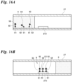
- FIG. 16 and Fig. 17 are diagrams illustrating an example of the method for measuring the mixed sample 9 using the analysis device 100 of the first embodiment.
- the sample 7 and the sample 8 flowing down the mixing flow passage 27 are disturbed to meander inside the flow passage by the plurality of protrusions 271, thereby generating the sample 9 in which the sample 7 and the sample 8 are mixed.
- the sample 9 in which the sample 7 and the sample 8 are mixed by the mixing flow passage 27 contains the magnetic insulator 91.
- the sample 9 in which the sample 7 and the sample 8 are mixed by the mixing flow passage 27 contains the magnetic insulator 91.
- the antibody 92 can be bound to the magnetic insulator 91 via the binder.
- the binder for example, streptavidin is used.
- the magnetic insulator 91 for example, yttrium iron garnet is used.
- the mixing flow passage 27 includes the electromagnet 272 at the downstream side with respect to the protrusion 271 on the inner surface. Therefore, in a case where the sample 9 in which the sample 7 and the sample 8 are mixed contains the magnetic insulator 91, when the sample 9 flows down the electromagnet 272, the sample 9 containing the magnetic insulator 91 is adhered by the electromagnet 272, and the sample 9 that does not adhere flows down to the downstream side with respect to the electromagnet 272.
- the reagent 95 is made to flow down from the fourth flow passage 243 to the joining portion 26, and is made to flow down to the mixing flow passage 27.
- the reagent 95 passes through the electromagnet 272, the reagent 95 is mixed with the sample 9 adhered to the electromagnet 272.
- the sample 9 mixed with the reagent 95 exhibits, for example, a color reaction.
- the irradiation unit 52 irradiates the sample 9 adhered to the electromagnet 272 with a light. Then, the measurement unit 53 measures the wavelength of a reflected light of the light emitted by the irradiation unit 52.
- the quantitative determination unit 42 refers to the relation between the wavelength measured by the measurement unit 53 and the content of the mixed sample 9 stored in the information processing device 4, thereby determining the quantity of the content of the mixed sample 9 based on the wavelength measured by the measurement unit 53. This allows facilitating the quantitative determination of the content of the mixed sample 9.
- the irradiation unit 52 that irradiates the sample 9 adhered to the electromagnet 272 with a light
- the measurement unit 53 that measures the wavelength of a reflected light of the irradiated light
- the quantitative determination unit 42 that determines the quantity of the mixed sample 9 based on the wavelength measured by the measurement unit 53 are provided. This allows facilitating the quantitative determination of the content of the mixed sample 9. Accordingly, the quantitative determination of the sample 9 can be quickly performed.
Landscapes
- Chemical & Material Sciences (AREA)
- Health & Medical Sciences (AREA)
- General Health & Medical Sciences (AREA)
- Analytical Chemistry (AREA)
- Life Sciences & Earth Sciences (AREA)
- Physics & Mathematics (AREA)
- Biochemistry (AREA)
- General Physics & Mathematics (AREA)
- Immunology (AREA)
- Pathology (AREA)
- Chemical Kinetics & Catalysis (AREA)
- Dispersion Chemistry (AREA)
- Hematology (AREA)
- Clinical Laboratory Science (AREA)
- Automatic Analysis And Handling Materials Therefor (AREA)
Abstract
Description
- The present invention relates to a dispensing device for dispensing a liquid sample, a mixing device, and an analysis device.
- Conventionally, as a technique for dispensing a sample, a dispensing device of
Patent Document 1 is disclosed. - The dispensing device of
Patent Document 1 employs a configuration including one ceramic heater that heats a part of a washing fluid filling a flow passage to generate a gas bubble and another ceramic heater that heats a washing fluid at a position closer to a syringe piston pump side than the heating position of the one ceramic heater to generate another gas bubble in a state where a layer of the washing fluid is interposed between the gas bubble and the other gas bubble. - Patent Document 1:
JP-A-2005-3610 - Incidentally, when a liquid sample is dispensed, the sample possibly remains inside a dispensing device. In the dispensing device of
Patent Document 1, the sample remaining inside the dispensing device is washed with the washing fluid. However, there are circumstances in which the accuracy of dispensing the sample is low due to the sample remaining inside the dispensing device. - Therefore, the present invention has been made in consideration of the above-described circumstances, and it is an object of the present invention to provide a technique capable of improving the dispensing accuracy of a liquid sample.
- A dispensing device according to the present invention is a dispensing device for dispensing a liquid sample that includes a cylindrical first flow passage, a pressing portion, and a press control unit. The first flow passage is provided with a cylindrical main body portion, an opening portion formed at the main body portion, and a lid portion that closes the opening portion and has higher flexibility than the main body portion. A liquid first sample flows down the first flow passage. The pressing portion is for pressing the lid portion. The press control unit controls the pressing of the pressing portion against the lid portion. The first flow passage is provided with a sample injection port formed at an upstream side with respect to the lid portion, and an injection portion for injecting a gas between the sample injection port and the lid portion.
- A mixing device according to the present invention is a mixing device that includes the dispensing device of the present invention and mixes the first sample and a second sample. The mixing device includes a second flow passage connected to the first flow passage at a downstream side with respect to the lid portion, a cylindrical third flow passage for making the second sample flow down, a joining portion at which the second flow passage joins the third flow passage, and a mixing flow passage for generating a mixed sample in which the first sample and the second sample are mixed at a downstream side with respect to the joining portion. At least any of the first sample and the second sample contains a magnetic insulator, and the mixing flow passage internally includes an electromagnet.
- An analysis device according to the present invention is an analysis device that includes the mixing device of the present invention and analyzes the mixed sample. The analysis device includes an irradiation unit that irradiates the mixed sample adhered to the electromagnet with a light, a measurement unit that measures a reflected light of the light emitted by the irradiation unit, and a quantitative determination unit that determines a quantity of the mixed sample based on a result of the measurement by the measurement unit.
- The present invention can provide the technique capable of improving the dispensing accuracy of a liquid sample.
-
-
Fig. 1 is a schematic diagram illustrating an example of an analysis device of a first embodiment. -
Fig. 2 is a diagram illustrating an example of a dispensing device of the first embodiment. -
Fig. 3 is diagrams for describing an example of a dispensing method using the dispensing device of the first embodiment,Fig. 3A is a diagram illustrating a state before dispensing by an injection portion, andFig. 3B is a diagram illustrating a state after dispensing by the injection portion. -
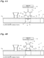
Fig. 4 is diagrams for describing an example of the dispensing method using the dispensing device of the first embodiment,Fig. 4A is a diagram illustrating a state in which a lid portion is pressed by a pressing portion, andFig. 4B is a diagram illustrating a state after the lid portion is pressed by the pressing portion. -
Fig. 5 is diagrams for describing an example of a dispensing method using a dispensing device of a first modification,Fig. 5A is a diagram illustrating a state before a lid portion is pressed by a pressing portion, andFig. 5B is a diagram illustrating a state in which the lid portion is pressed by the pressing portion. -
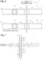
Fig. 6 is a diagram illustrating an example of a dispensing device of a second modification. -
Fig. 7 is a diagram illustrating an example of a mixing device of the first embodiment. -
Fig. 8 is diagrams for describing a method for dispensing a liquid sample using a third flow passage,Fig. 8A is a diagram illustrating a state before dispensing by an injection portion, andFig. 8B is a diagram illustrating a state after dispensing by the injection portion. -
Fig. 9 is a diagram illustrating an example of a method for mixing a sample and another sample by the mixing device of the first embodiment. -
Fig. 10 is a diagram illustrating an example of the method for mixing a sample and another sample by the mixing device of the first embodiment. -
Fig. 11 is a diagram illustrating an example of the method for mixing a sample and another sample by the mixing device of the first embodiment. -
Fig. 12 is a diagram illustrating an example of a mixing device of the first modification. -
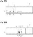
Fig. 13 is diagrams illustrating an example of a method for mixing a sample and another sample using the mixing device of the first modification,Fig. 13A is a diagram illustrating a state before a sample is adhered to an electromagnet, andFig. 13B is a diagram illustrating a state after the sample is adhered to the electromagnet. -
Fig. 14 is diagrams illustrating an example of the method for mixing a sample and another sample using the mixing device of the first modification,Fig. 14A is a diagram illustrating a state before the samples are mixed, andFig. 14B is a diagram illustrating a state after the samples are mixed. -
Fig. 15 is a diagram illustrating an analysis device in which a mixing device is provided with an irradiation unit and a measurement unit. -
Fig. 16 is diagrams illustrating an example of a method for measuring the mixed sample using the analysis device of the first embodiment,Fig. 16A is a diagram illustrating a state before the sample is adhered to an electromagnet, andFig. 16B is a diagram illustrating a state after the sample is adhered to the electromagnet. -
Fig. 17 is diagrams illustrating an example of the method for measuring the mixed sample using the analysis device of the first embodiment,Fig. 17A is a diagram illustrating a state before a reagent is mixed, andFig. 17B is a diagram illustrating a state after the reagent is mixed. -
Fig. 18 is a diagram illustrating an example of the method for measuring the mixed sample using the analysis device of the first embodiment. - The following describes embodiments of a dispensing device, a mixing device, and an analysis device to which the present invention is applied in detail with reference to the drawings.
-
Fig. 1 is a schematic diagram illustrating an example of ananalysis device 100 of a first embodiment. As illustrated inFig. 1 , theanalysis device 100 includes adispensing device 1, amixing device 2, aninformation processing device 4, animaging device 51, anirradiation unit 52, and ameasurement unit 53. Theanalysis device 100 analyzes a sample, such as a liquid specimen. -
Fig. 2 is a diagram illustrating an example of thedispensing device 1 of the first embodiment. As illustrated inFig. 2 , thedispensing device 1 dispenses aliquid sample 7. Thedispensing device 1 is provided with afirst flow passage 11, apressing portion 12, and apress control unit 13. - In the
first flow passage 11, theliquid sample 7 flows down. Thefirst flow passage 11 is provided with asample injection port 11a at an upstream side in a flow-down direction of thesample 7. Thesample injection port 11a is, for example, provided with a sample injection device (not illustrated), and the sample injection device can inject thesample 7 into thefirst flow passage 11. The sample injection device is connected to theinformation processing device 4, and an injection timing, a flow-down speed, a flow-down amount, and the like of thesample 7 injected into thefirst flow passage 11 can be controlled by aprocessing unit 49 of theinformation processing device 4. - The
first flow passage 11 is provided with a cylindricalmain body portion 14, an openingportion 15 formed at a sidewall of themain body portion 14, and alid portion 16 that closes the openingportion 15 and has higher flexibility than themain body portion 14. - The material of the
main body portion 14 is, for example, glass. The openingportion 15 is an opening formed in a circular shape, a rectangular shape, or the like at a part of the sidewall of themain body portion 14. The material of thelid portion 16 is, for example, soft plastic, such as polyethylene, having higher flexibility than themain body portion 14. The inner surface of thelid portion 16 is preferably formed to be flush with the inner surface of themain body portion 14. - The
pressing portion 12 presses thelid portion 16 from the outside of thefirst flow passage 11. By pressing thelid portion 16 by thepressing portion 12, thelid portion 16 can be bent toward the inside of thefirst flow passage 11. Thepressing portion 12 includes a plurality ofblade portions 18 rotatable around arotation shaft 17. - The
press control unit 13 controls the pressing of thepressing portion 12 against thelid portion 16. For thepress control unit 13, for example, a motor that rotates therotation shaft 17 of thepressing portion 12 at constant speed is used. By rotating therotation shaft 17 by thepress control unit 13, the pressing of theblade portion 18 against thelid portion 16 and the separation of theblade portion 18 from thelid portion 16 can be alternately performed. The control of the pressing of thepressing portion 12 by thepress control unit 13 can be controlled by theprocessing unit 49 of theinformation processing device 4. - The
first flow passage 11 is provided with aninjection portion 19 for injecting a gas, such as air, between thesample injection port 11a and thelid portion 16 at the sidewall. By injecting the gas from theinjection portion 19, a sample flowing down from thesample injection port 11a can be dispensed at a predetermined amount. Theinjection portion 19 is, for example, provided with a gas injection device (not illustrated), and the gas injection device can inject the gas into thefirst flow passage 11. The gas injection device is connected to theinformation processing device 4, and an injection timing, an injection amount, and the like of the gas injected into thefirst flow passage 11 can be controlled by, for example, theprocessing unit 49 of theinformation processing device 4. Thefirst flow passage 11 is connected to themixing device 2 at a downstream side with respect to thelid portion 16. - Next, a method for dispensing a liquid sample using the
dispensing device 1 is described. - As illustrated in
Fig. 3A , in the method for dispensing a sample using thedispensing device 1, thesample 7 is continuously injected into thefirst flow passage 11 from thesample injection port 11a. - As illustrated in
Fig. 3B , a predetermined amount of an air S is injected from theinjection portion 19. Thesample 7 injected into thefirst flow passage 11 is divided into asample 7a at a downstream side and asample 7b at an upstream side with respect to theinjection portion 19 by the air S. When the air S is injected from theinjection portion 19, asample 7c remains in the air S between thesample 7a at the downstream side and thesample 7b at the upstream side with respect to theinjection portion 19 in some cases. In this case, the dispensing accuracy of thesample 7a at the downstream side with respect to theinjection portion 19 is reduced by the amount of thesample 7c remaining in the air S. - As illustrated in
Fig. 4A , when thesample 7 is made to flow down and the air S flows down thelid portion 16, thelid portion 16 is pressed by thepressing portion 12. In detail, thepress control unit 13 rotates therotation shaft 17, thereby pressing thelid portion 16 with theblade portion 18 provided at therotation shaft 17. This allows thelid portion 16 to be bent to the inside of thefirst flow passage 11. Bending thelid portion 16 causes thesample 7c remaining in the air S to be extruded to the downstream side and integrated with thesample 7a at the downstream side. Therefore, the dispensing accuracy of thesample 7a at the downstream side can be improved. - Then, as illustrated in
Fig. 4B , thepress control unit 13 further rotates therotation shaft 17 to separate theblade portion 18 provided at therotation shaft 17 from thelid portion 16. - By repeating the above-described procedure, the
dispensing device 1 can sequentially dispense thesample 7. - According to the embodiment, the
pressing portion 12 for pressing thelid portion 16 and thepress control unit 13 that controls the pressing of thepressing portion 12 against thelid portion 16 are provided. This allows thepressing portion 12 to bend thelid portion 16 to the inside of thefirst flow passage 11 when the air S flows down thelid portion 16. Therefore, thesample 7c remaining in the air S is extruded to the downstream side and integrated with thesample 7a at the downstream side. Accordingly, the dispensing accuracy of thesample 7 can be improved. - According to the embodiment, the
pressing portion 12 is provided with the plurality ofblade portions 18 rotatable around therotation shaft 17, and thepress control unit 13 rotates therotation shaft 17. This allows facilitating control of the pressing timing of theblade portion 18 against thelid portion 16. Therefore, thesample 7 can be dispensed with high efficiency. - According to the embodiment, the inner surface of the
lid portion 16 is flush with the inner surface of themain body portion 14. This allows thesample 7 to smoothly flow down inside thefirst flow passage 11 even after the air S is injected into thefirst flow passage 11 by theinjection portion 19. Therefore, thesample 7c remaining in the air S is less likely to remain in thefirst flow passage 11. Consequently, by bending thelid portion 16, thesample 7c remaining in the air S is smoothly extruded to the downstream side and integrated with thesample 7a at the downstream side. Therefore, the dispensing accuracy of thesample 7 can be further improved. - Next, a first modification of the
dispensing device 1 is described.Fig. 5 is diagrams illustrating thedispensing device 1 of the first modification. As illustrated inFig. 5A , in thedispensing device 1, thepress control unit 13 allows thepressing portion 12 to move in directions intersecting with the flow-down direction of the sample 7 (directions of an arrow A in the diagram). This allows thepressing portion 12 to bend thelid portion 16 to the inside of thefirst flow passage 11 when the air S flows down thelid portion 16. Therefore, as illustrated inFig. 5B , thesample 7c remaining in the air S is extruded to the downstream side and integrated with thesample 7a at the downstream side. - According to the embodiment, the
press control unit 13 allows thepressing portion 12 to move in the directions intersecting with the flow-down direction of thesample 7. This allows easily bending thelid portion 16 to the inside of thefirst flow passage 11 when thepressing portion 12 presses thelid portion 16. By bending thelid portion 16, thesample 7c remaining in the air S is extruded to the downstream side and integrated with thesample 7a at the downstream side. Therefore, the dispensing accuracy of thesample 7a at the downstream side can be improved. - Next, a second modification of the
dispensing device 1 is described.Fig. 6 is a diagram illustrating thedispensing device 1 of the second modification. In thedispensing device 1, a plurality of thefirst flow passages 11 are provided, and one pressingportion 12 can simultaneously press thelid portions 16 provided at the respectivefirst flow passages 11. - The one pressing
portion 12 is provided across a plurality of thelid portions 16, and can simultaneously press the plurality oflid portions 16. Thepressing portion 12 allows, for example, thepressing portion 12 to move in directions intersecting with the flow-down direction of the sample 7 (a near side direction and a far side direction of the paper surface ofFig. 6 ). - According to the embodiment, the plurality of
first flow passages 11 are provided, and one pressingportion 12 can simultaneously press the plurality oflid portions 16. This allows simultaneously dispensing thesample 7 flowing down the plurality offirst flow passages 11. Therefore, thesample 7 can be dispensed with high efficiency. -
Fig. 7 is a diagram illustrating an example of themixing device 2 of the first embodiment. Themixing device 2 includes thedispensing device 1, and mixes theliquid sample 7 and aliquid sample 8. Themixing device 2 is connected to thefirst flow passage 11 of thedispensing device 1. - The
mixing device 2 is provided with asecond flow passage 22, athird flow passage 23, afourth flow passage 24, a joiningportion 26, and amixing flow passage 27. Thefourth flow passage 24 may be omitted. In themixing device 2, a direction toward the mixingflow passage 27 is defined as the flow-down direction. - The
second flow passage 22 is connected to thefirst flow passage 11 of thedispensing device 1 at the downstream side with respect to thelid portion 16. Thesecond flow passage 22 may be integrally formed with thefirst flow passage 11. Thesecond flow passage 22 may be formed separately from thefirst flow passage 11 and connected via a connecting pipe that connects thefirst flow passage 11 to thesecond flow passage 22. A plurality of thesecond flow passages 22 may be provided. - In the
third flow passage 23, thesample 8 different from thesample 7 flows down. Thethird flow passage 23 is formed in a cylindrical shape. Thethird flow passage 23 is transparent. Thethird flow passage 23 is provided with asample injection port 23a to inject thesample 8. Thesample injection port 23a is, for example, provided with a sample injection device (not illustrated), and the sample injection device can inject the sample into thethird flow passage 23. The sample injection device is connected to theinformation processing device 4, and an injection timing, a flow-down speed, a flow-down amount, and the like of the sample injected into thethird flow passage 23 can be controlled by, for example, theprocessing unit 49 of theinformation processing device 4. - The
third flow passage 23 is provided with aninjection portion 29 for injecting a gas, such as air, at a sidewall at the downstream side with respect to thesample injection port 23a. By injecting the gas from theinjection portion 29, thesample 8 flowing down from thesample injection port 23a can be dispensed at a predetermined amount. Theinjection portion 29 is, for example, provided with a gas injection device (not illustrated), and the gas injection device can inject a gas into thethird flow passage 23. The gas injection device is connected to theinformation processing device 4, and an injection timing, an injection amount, and the like of the gas injected into thethird flow passage 23 can be controlled by, for example, theprocessing unit 49 of theinformation processing device 4. - The
third flow passage 23 is provided with the joiningportion 26 for joining thesecond flow passage 22 at an end portion on the opposite side of thesample injection port 23a. A plurality of thethird flow passages 23 may be provided. - The
third flow passage 23 is provided with a plurality of double truncated cone-shapedportions 28, each of which is formed with a pair of anenlarged width portion 281 enlarged in width from the upstream side toward the downstream side of the flow-down direction and a reducedwidth portion 282 provided continuously with theenlarged width portion 281 at the downstream side and reduced in width from the upstream side toward the downstream side. The plurality of double truncated cone-shapedportions 28 are continuously provided. One double truncated cone-shapedportion 28 has an internal volume of, for example, 1 mm as a known value. - The mixing
flow passage 27 generates asample 9 in which thesample 7 and thesample 8 are mixed. The mixingflow passage 27 is provided at the downstream side of the flow-down direction with respect to the joiningportion 26. The mixingflow passage 27 is formed in a cylindrical shape. - The mixing
flow passage 27 is provided with a plurality ofprotrusions 271 on the inner surface. Theprotrusions 271 are formed to be inclined toward the upstream side. Theprotrusions 271 are provided at predetermined intervals along the mixingflow passage 27. Theprotrusions 271 are provided alternately on both sides of the inner surface across a center axis along the flow-down direction. Thesample 7 and thesample 8 flowing down the mixingflow passage 27 are disturbed to meander inside the flow passage by the plurality ofprotrusions 271, thereby allowing efficiently mixing thesample 7 and thesample 8 to generate thesample 9. - In the
fourth flow passage 24, a fluid different from thesample 7 and thesample 8 flows down. The fluid flowing down thefourth flow passage 24 is, for example, a gas, such as air, an oil, a washing fluid, and a reagent. Thefourth flow passage 24 joins thesecond flow passage 22. Thefourth flow passage 24 is formed in a cylindrical shape. Thefourth flow passage 24 is transparent. - The
fourth flow passage 24 is provided with aninjection port 24a to inject the fluid. Theinjection port 24a is, for example, provided with an injection device (not illustrated), and the injection device can inject the fluid into thefourth flow passage 24. The injection device is connected to theinformation processing device 4, and an injection timing, a flow-down speed, a flow-down amount, and the like of the fluid injected into thefourth flow passage 24 can be controlled by, for example, theprocessing unit 49 of theinformation processing device 4. - The
fourth flow passage 24 is provided with the joiningportion 26 for joining thesecond flow passage 22 at an end portion on the opposite side of theinjection port 24a. - The
fourth flow passage 24 is provided with a plurality of double truncated cone-shapedportions 28, each of which is formed with a pair of anenlarged width portion 281 enlarged in width from the upstream side toward the downstream side of the flow-down direction and a reducedwidth portion 282 provided continuously with theenlarged width portion 281 at the downstream side and reduced in width from the upstream side toward the downstream side. The plurality of double truncated cone-shapedportions 28 are continuously provided. One double truncated cone-shapedportion 28 has an internal volume of, for example, 1 mm as a known value. - The
fourth flow passage 24 includes afourth flow passage 241 in which a fluid inactive to thesample 7 and thesample 8 flows down. As the inactive fluid, for example, air or an oil is used. This allows the inactive fluid to be interposed between themixed samples 9. Accordingly, it can be avoided that themixed samples 9 on both sides across the inactive fluid are mixed. - Next, a method for dispensing a liquid sample using the
third flow passage 23 is described.Fig. 8 is diagrams for describing the method for dispensing a liquid sample using thethird flow passage 23. - As illustrated in
Fig. 8A , in the method for dispensing a sample using thethird flow passage 23, thesample 8 is continuously injected into thethird flow passage 23 from thesample injection port 23a. Then, by injecting a predetermined amount of the air S from theinjection portion 29, thesample 8 injected into thethird flow passage 23 is dispensed at a predetermined amount by the air S. - When the air S is injected from the
injection portion 29, thesample 8 fills one or the plurality of double truncated cone-shapedportions 28 at the downstream side with respect to theinjection portion 29. Since the internal volume of the double truncated cone-shapedportion 28 is already known, the volume of thesample 8 inside the double truncated cone-shapedportion 28 can be obtained from the appearance without adding a scale to thethird flow passage 23. Therefore, the dispensing efficiency of thesample 8 can be improved. - By repeating the above-described procedure, the
sample 8 can be sequentially dispensed by thethird flow passage 23. - The
mixing device 2 may further include theimaging device 51 and theinformation processing device 4. This allows facilitating an estimation of the volume of thesample 8 dispensed by thethird flow passage 23. - The
imaging device 51 takes an image of the double truncated cone-shapedportions 28 provided at the downstream side with respect to theinjection portion 29. For theimaging device 51, for example, a camera is used. - For the
information processing device 4, for example, a personal computer is used. Theinformation processing device 4 includes, for example, anestimation unit 41. Further, theinformation processing device 4 may further include an input/output unit that inputs and outputs various kinds of information and a storage unit that stores the various kinds of information. - The
information processing device 4 preliminarily stores, for example, a relation between an image taken by theimaging device 51 and the volume of thesample 8 filling the double truncated cone-shapedportion 28. - The
estimation unit 41 estimates the volume of the sample inside the double truncated cone-shapedportion 28 based on the image taken by theimaging device 51. For example, theestimation unit 41 refers to the relation between the image taken by theimaging device 51 and the volume of thesample 8 inside the double truncated cone-shapedportion 28 stored in theinformation processing device 4, thereby estimating the volume of thesample 8 inside the double truncated cone-shapedportion 28 based on the image of theimaging device 51. This allows facilitating an estimation of the volume of thesample 8 in the double truncated cone-shapedportion 28. - Next, an example of a method for mixing the
sample 7 and thesample 8 using themixing device 2 is described.Fig. 9 to Fig. 11 are diagrams illustrating an example of the method for mixing thesample 7 and thesample 8 using themixing device 2 of the first embodiment. - As illustrated in
Fig. 9 , in the mixing method using themixing device 2, thesample 8 is continuously injected into thethird flow passage 23 from thesample injection port 23a. Then, by injecting a predetermined amount of air from theinjection portion 29, thesample 8 injected into thethird flow passage 23 is dispensed at a predetermined amount by the air. The dispensedsample 8 is made to flow down to the joiningportion 26. - As illustrated in
Fig. 10 , thesample 7 dispensed by the dispensingdevice 1 is made to flow down from thefirst flow passage 11 to the joiningportion 26 via thesecond flow passage 22. Then, thesample 7 and thesample 8 are made to flow down to themixing flow passage 27. Subsequently, the inactive fluid, such as air, is injected into thefourth flow passage 241 from theinjection port 24a, and the inactive fluid, such as air, is made to flow down to the joiningportion 26. - As illustrated in
Fig. 11 , thesample 7 and thesample 8 flowing down the mixingflow passage 27 are disturbed to meander inside the flow passage by the plurality ofprotrusions 271, thereby mixing thesample 7 and thesample 8. Thus, thesample 9 in which thesample 7 and thesample 8 are mixed is generated. - The inactive fluid flowing down to the joining
portion 26 flows down the mixingflow passage 27. Then, thesample 8 dispensed to the joiningportion 26 is made to flow down, and the above-described procedure is repeated. Thus, thesample 7 and thesample 8 can be sequentially mixed by themixing device 2. - A first modification of the
mixing device 2 is described.Fig. 12 is a diagram illustrating an example of themixing device 2 of the first modification. At least any of thesample 7 and thesample 8 contains a magnetic insulator. - The mixing
flow passage 27 internally includes anelectromagnet 272. Therefore, in a case where at least any of thesample 7 and thesample 8 contains a magnetic insulator, when thesample 7 and thesample 8 flow down the mixingflow passage 27, at least any of thesample 7 and thesample 8 can be adhered by theelectromagnet 272. Theelectromagnet 272 provided inside the mixingflow passage 27 may be a magnet. - The
electromagnet 272 is connected to a current control device (not illustrated). When the current control device makes a current flow, theelectromagnet 272 can cause the sample containing a magnetic insulator to be adhered by theelectromagnet 272. When the current control device does not make a current flow, theelectromagnet 272 can cause the sample adhered by theelectromagnet 272 to be detached from theelectromagnet 272. - The
fourth flow passage 24 further includes afourth flow passage 242 in which a washing fluid for washing theelectromagnet 272 flows down. For the washing fluid, for example, water is used. This allows washing impurities and the like adhering to theelectromagnet 272. Thefourth flow passage 242 may be provided with a joiningportion 26 for joining the mixingflow passage 27 at the upstream side with respect to theelectromagnet 272. - Next, an example of a method for mixing the
sample 7 and thesample 8 using themixing device 2 of the first modification is described.Fig. 13 is diagrams illustrating an example of the method for mixing thesample 7 and thesample 8 using themixing device 2 of the first modification. In the following example, thesample 7 contains anantigen 93. Thesample 8 contains anantibody 92 bound to amagnetic insulator 91 via a binder. In this case, when thesample 7 and thesample 8 are mixed, thesample 9 in which theantigen 93 is bound to theantibody 92 is generated. In the present invention, for example, thesample 7 may contain an enzyme, and thesample 8 may contain a substrate. In this case, when thesample 7 and thesample 8 are mixed, thesample 9 in which the enzyme is bound to the substrate is generated. - In the mixing method using the
mixing device 2, thesample 8 is continuously injected into thethird flow passage 23 from thesample injection port 23a. Then, by injecting a predetermined amount of air from theinjection portion 29, thesample 8 injected into thethird flow passage 23 is dispensed at a predetermined amount by the air. The dispensedsample 8 is made to flow down to the joiningportion 26, and is made to flow down to themixing flow passage 27. - As illustrated in
Fig. 13A , thesample 8 contains theantibody 92 bound to themagnetic insulator 91 via the binder. A current is applied to theelectromagnet 272, and theelectromagnet 272 has a magnetic property. Therefore, as illustrated inFig. 13B , when thesample 8 passes through theelectromagnet 272, themagnetic insulator 91 contained in thesample 8 adheres to theelectromagnet 272, and thesample 8 that does not adhere flows down to the downstream side with respect to theelectromagnet 272. - Then, as illustrated in
Fig. 14A , thesample 7 dispensed by the dispensingdevice 1 is made to flow down from thefirst flow passage 11 to the joiningportion 26 via thesecond flow passage 22, and is made to flow down to themixing flow passage 27. Thesample 7 contains theantigen 93 capable of binding to theantibody 92. - Therefore, as illustrated in
Fig. 14B , when thesample 7 passes through theelectromagnet 272, theantigen 93 contained in thesample 7 binds to theantibody 92 adhered to theelectromagnet 272, and thesample 7 that does not bind flows down to the downstream side with respect to theelectromagnet 272. - Thus, the
sample 8 containing themagnetic insulator 91 is adhered by theelectromagnet 272, and thesample 7 different from the adheredsample 8 is made to flow down to theelectromagnet 272, thereby allowing the generation of thesample 9 in which thesample 7 and thesample 8 are mixed. - After the
mixed sample 9 is generated, a washing fluid is made to flow down thefourth flow passage 242 from theinjection port 24a to the joiningportion 26. The washing fluid flowing down to the joiningportion 26 flows down the mixingflow passage 27 and washes theelectromagnet 272. - After the washing with the washing fluid, a measurement by the
measurement unit 53 described later may be performed on themixed sample 9. After the end of the measurement, the current to theelectromagnet 272 is released, and thesample 9 is detached from theelectromagnet 272. Then, it is only necessary to make the washing fluid flow down the mixingflow passage 27 again to wash theelectromagnet 272. - Then, the
sample 8 dispensed to the joiningportion 26 is made to flow down, and the above-described procedure is repeated. Thus, thesample 7 and thesample 8 can be sequentially mixed by themixing device 2. - According to the embodiment, the mixing
flow passage 27 for generating thesample 9 in which thesample 7 and thesample 8 are mixed is provided at the downstream side with respect to the joiningportion 26, at least any of thesample 7 and thesample 8 contains the magnetic insulator, and the mixingflow passage 27 internally includes theelectromagnet 272. Accordingly, for example, thesample 8 containing themagnetic insulator 91 is adhered by theelectromagnet 272, and thesample 7 different from the adheredsample 8 is made to flow down to theelectromagnet 272, thereby allowing the generation of thesample 9 in which thesample 7 and thesample 8 are mixed. - According to the embodiment, the mixing
flow passage 27 internally includes theelectromagnet 272. This facilitates a recovery work of thesample 9 adhered to theelectromagnet 272 after the generation of thesample 9 by mixing thesample 7 and thesample 8 in themixing flow passage 27. Therefore, the generation of thesample 9 can be easily repeated. - According to the embodiment, the
third flow passage 23 is provided with the plurality of double truncated cone-shapedportions 28, each of which is formed with a pair of theenlarged width portion 281 enlarged in width from the upstream side toward the downstream side and the reducedwidth portion 282 provided continuously with theenlarged width portion 281 at the downstream side and reduced in width from the upstream side toward the downstream side. Accordingly, the volume of thesample 8 inside the double truncated cone-shapedportion 28 can be obtained from the appearance without adding a scale to thethird flow passage 23. Therefore, the dispensing efficiency of thesample 8 can be improved. - Next, the
analysis device 100 is described. Theanalysis device 100 includes thedispensing device 1 and themixing device 2, and analyzes themixed sample 9.Fig. 15 is a diagram illustrating theanalysis device 100 in which themixing device 2 is provided with theirradiation unit 52 and themeasurement unit 53. Themixing device 2 includes theirradiation unit 52 and themeasurement unit 53. Theelectromagnet 272 is provided at the downstream side with respect to theprotrusions 271. - The
irradiation unit 52 irradiates thesample 9 adhered to theelectromagnet 272 with a light. Theirradiation unit 52 emits a light having a predetermined wavelength, for example, an ultraviolet light, an infrared light, and a visible light. - For the
measurement unit 53, a publicly known wavelength measurement device is used, and themeasurement unit 53 measures a wavelength of a reflected light of the light emitted by theirradiation unit 52. For themeasurement unit 53, a publicly known light intensity measurement device is used, and themeasurement unit 53 may measure an intensity of a reflected light of the light emitted by theirradiation unit 52. - The
information processing device 4 includes, for example, aquantitative determination unit 42. Theinformation processing device 4 preliminarily stores, for example, a relation between a wavelength measured by themeasurement unit 53 and a content of themixed sample 9. Theinformation processing device 4 can control the light irradiation by theirradiation unit 52, the measurement by themeasurement unit 53, and the like with theprocessing unit 49. - The
quantitative determination unit 42 determines a quantity of the content of themixed sample 9 based on the wavelength measured by themeasurement unit 53. For example, thequantitative determination unit 42 refers to the relation between the wavelength measured by themeasurement unit 53 and the content of themixed sample 9 stored in theinformation processing device 4, thereby determining the quantity of the content of themixed sample 9 based on the wavelength measured by themeasurement unit 53. This allows facilitating the quantitative determination of the content of themixed sample 9. For example, the quantity of the content of the antibody, the antigen, the enzyme, the substrate, or the like contained in thesample 9 can be determined. - The
fourth flow passage 24 may further include, for example, afourth flow passage 243 in which aliquid reagent 95 reactive to themixed sample 9 flows down. This allows mixing thereagent 95 with themixed sample 9. - Next, an example of a method for measuring the
mixed sample 9 using theanalysis device 100 of the first embodiment is described.Fig. 16 andFig. 17 are diagrams illustrating an example of the method for measuring themixed sample 9 using theanalysis device 100 of the first embodiment. - As illustrated in
Fig. 16A , in the measuring method, thesample 7 and thesample 8 flowing down the mixingflow passage 27 are disturbed to meander inside the flow passage by the plurality ofprotrusions 271, thereby generating thesample 9 in which thesample 7 and thesample 8 are mixed. - At least any of the
sample 7 and thesample 8 contains themagnetic insulator 91. In this case, thesample 9 in which thesample 7 and thesample 8 are mixed by the mixingflow passage 27 contains themagnetic insulator 91. For example, in a case where thesample 7 contains theantibody 92 bound to theantigen 93 and thesample 8 contains themagnetic insulator 91 and the binder, when thesample 7 and thesample 8 are mixed via theprotrusions 271, theantibody 92 can be bound to themagnetic insulator 91 via the binder. As the binder, for example, streptavidin is used. As themagnetic insulator 91, for example, yttrium iron garnet is used. - The mixing
flow passage 27 includes theelectromagnet 272 at the downstream side with respect to theprotrusion 271 on the inner surface. Therefore, in a case where thesample 9 in which thesample 7 and thesample 8 are mixed contains themagnetic insulator 91, when thesample 9 flows down theelectromagnet 272, thesample 9 containing themagnetic insulator 91 is adhered by theelectromagnet 272, and thesample 9 that does not adhere flows down to the downstream side with respect to theelectromagnet 272. - Then, as illustrated in
Fig. 17A , thereagent 95 is made to flow down from thefourth flow passage 243 to the joiningportion 26, and is made to flow down to themixing flow passage 27. - As illustrated in
Fig. 17B , when thereagent 95 passes through theelectromagnet 272, thereagent 95 is mixed with thesample 9 adhered to theelectromagnet 272. Thesample 9 mixed with thereagent 95 exhibits, for example, a color reaction. - Then, as illustrated in
Fig. 18 , theirradiation unit 52 irradiates thesample 9 adhered to theelectromagnet 272 with a light. Then, themeasurement unit 53 measures the wavelength of a reflected light of the light emitted by theirradiation unit 52. - Then, for example, the
quantitative determination unit 42 refers to the relation between the wavelength measured by themeasurement unit 53 and the content of themixed sample 9 stored in theinformation processing device 4, thereby determining the quantity of the content of themixed sample 9 based on the wavelength measured by themeasurement unit 53. This allows facilitating the quantitative determination of the content of themixed sample 9. - According to the embodiment, the
irradiation unit 52 that irradiates thesample 9 adhered to theelectromagnet 272 with a light, themeasurement unit 53 that measures the wavelength of a reflected light of the irradiated light, and thequantitative determination unit 42 that determines the quantity of themixed sample 9 based on the wavelength measured by themeasurement unit 53 are provided. This allows facilitating the quantitative determination of the content of themixed sample 9. Accordingly, the quantitative determination of thesample 9 can be quickly performed. - While the embodiments of the present invention have been described above, these embodiments have been presented by way of example, and are not intended to limit the scope of the invention. These embodiments can be embodied in combination as necessary. Further, the present invention can be embodied in various novel embodiments in addition to the above-described embodiments. Therefore, for each of the above-described embodiments, various omissions, substitutions, and changes can be made without departing from the gist of the invention. Such novel embodiments and modifications fall within the scope and the gist of the invention and within the scope of the inventions described in the claims and their equivalents.
-
- 100:
- Analysis device
- 1:
- Dispensing device
- 11:
- First flow passage
- 11a:
- Sample injection port
- 12:
- Pressing portion
- 13:
- Press control unit
- 14:
- Main body portion
- 15:
- Opening portion
- 16:
- Lid portion
- 17:
- Rotation shaft
- 18:
- Blade portion
- 19:
- Injection portion
- 2:
- Mixing device
- 22:
- Second flow passage
- 23:
- Third flow passage
- 23a:
- Sample injection port
- 24:
- Fourth flow passage
- 24a:
- Injection port
- 241:
- Fourth flow passage
- 242:
- Fourth flow passage
- 243:
- Fourth flow passage
- 26:
- Joining portion
- 27:
- Mixing flow passage
- 271:
- Protrusion
- 272:
- Electromagnet
- 28:
- Double truncated cone-shaped portion
- 281:
- Enlarged width portion
- 282:
- Reduced width portion
- 29:
- Injection portion
- 4:
- Information processing device
- 41:
- Estimation unit
- 42:
- Quantitative determination unit
- 49:
- Processing unit
- 51:
- Imaging device
- 52:
- Irradiation unit
- 53:
- Measurement unit
- 7:
- Sample
- 8:
- Sample
- 9:
- Sample
- 91:
- Magnetic insulator
- 92:
- Antibody
- 93:
- Antigen
- 95:
- Reagent
Claims (6)
- A dispensing device for dispensing a liquid sample, comprising:a cylindrical first flow passage provided with a cylindrical main body portion, an opening portion formed at the main body portion, and a lid portion that closes the opening portion and has higher flexibility than the main body portion, a liquid first sample flowing down the first flow passage;a pressing portion for pressing the lid portion; anda press control unit that controls the pressing of the pressing portion against the lid portion, whereinthe first flow passage is provided with:a sample injection port formed at an upstream side with respect to the lid portion; andan injection portion for injecting a gas between the sample injection port and the lid portion.
- The dispensing device according to claim 1, whereinthe pressing portion includes a plurality of blade portions rotatable around a rotation shaft, andthe press control unit rotates the rotation shaft.
- The dispensing device according to claim 1, whereina plurality of the first flow passages are provided, andone pressing portion is configured to simultaneously press a plurality of the lid portions.
- A mixing device that includes the dispensing device according to claim 1 and mixes the first sample and a second sample, the mixing device comprising:a second flow passage connected to the first flow passage at a downstream side with respect to the lid portion;a cylindrical third flow passage for making the second sample flowing down;a joining portion at which the second flow passage joins the third flow passage; anda mixing flow passage for generating a mixed sample in which the first sample and the second sample are mixed at a downstream side with respect to the joining portion, whereinat least any of the first sample and the second sample contains a magnetic insulator, andthe mixing flow passage internally includes an electromagnet.
- The mixing device according to claim 4, wherein
the third flow passage is provided with a plurality of double truncated cone-shaped portions, and the double truncated cone-shaped portion is formed with a pair of an enlarged width portion enlarged in width from an upstream side toward a downstream side and a reduced width portion provided continuously with the enlarged width portion at the downstream side and reduced in width from the upstream side toward the downstream side. - An analysis device that includes the mixing device according to claim 4 and analyzes the mixed sample, the analysis device comprising:an irradiation unit that irradiates the mixed sample adhered to the electromagnet with a light;a measurement unit that measures a reflected light of the light emitted by the irradiation unit; anda quantitative determination unit that determines a quantity of the mixed sample based on a result of the measurement by the measurement unit.
Applications Claiming Priority (2)
| Application Number | Priority Date | Filing Date | Title |
|---|---|---|---|
| JP2022119730 | 2022-07-27 | ||
| PCT/JP2023/025746 WO2024024511A1 (en) | 2022-07-27 | 2023-07-12 | Dispensing device, mixing device, and analysis device |
Publications (2)
| Publication Number | Publication Date |
|---|---|
| EP4564010A1 true EP4564010A1 (en) | 2025-06-04 |
| EP4564010A4 EP4564010A4 (en) | 2026-08-05 |
Family
ID=89706290
Family Applications (1)
| Application Number | Title | Priority Date | Filing Date |
|---|---|---|---|
| EP23846242.8A Pending EP4564010A4 (en) | 2022-07-27 | 2023-07-12 | Dispensing device, mixing device and analysis device |
Country Status (3)
| Country | Link |
|---|---|
| EP (1) | EP4564010A4 (en) |
| JP (1) | JP7854669B2 (en) |
| WO (1) | WO2024024511A1 (en) |
Family Cites Families (7)
| Publication number | Priority date | Publication date | Assignee | Title |
|---|---|---|---|---|
| JPH09189704A (en) * | 1996-01-10 | 1997-07-22 | Hitachi Ltd | Automatic chemical analyzer |
| CN1093782C (en) * | 1996-07-26 | 2002-11-06 | 拜奥-多特公司 | Method and apparatus for dispensing liquid onto a substrate |
| JP2005003610A (en) | 2003-06-13 | 2005-01-06 | Olympus Corp | Dispenser, and automatic analyzer equipped with the same |
| EP1745851B1 (en) * | 2005-07-22 | 2015-02-25 | Tecan Trading AG | Process, device and computerprogramm product for the classification of a liquid |
| US8029744B2 (en) * | 2005-11-16 | 2011-10-04 | Hitachi, Ltd. | Method of liquid droplet formation and transport apparatus therefor and particle manipulating apparatus |
| US8852952B2 (en) * | 2008-05-03 | 2014-10-07 | Advanced Liquid Logic, Inc. | Method of loading a droplet actuator |
| JP2011137676A (en) * | 2009-12-28 | 2011-07-14 | Hitachi High-Technologies Corp | Dispensing apparatus, automatic analyzer, and method of measuring amount of liquid |
-
2023
- 2023-07-12 WO PCT/JP2023/025746 patent/WO2024024511A1/en not_active Ceased
- 2023-07-12 JP JP2024536954A patent/JP7854669B2/en active Active
- 2023-07-12 EP EP23846242.8A patent/EP4564010A4/en active Pending
Also Published As
| Publication number | Publication date |
|---|---|
| EP4564010A4 (en) | 2026-08-05 |
| JPWO2024024511A1 (en) | 2024-02-01 |
| WO2024024511A1 (en) | 2024-02-01 |
| JP7854669B2 (en) | 2026-05-07 |
Similar Documents
| Publication | Publication Date | Title |
|---|---|---|
| JP4683538B2 (en) | Analysis system and analysis method including microchip for analysis | |
| CN110441472B (en) | Flow cell with integrated manifold | |
| US20190033307A1 (en) | Analytical Measuring and Evaluation Method for Molecular Interactions | |
| AU768861B2 (en) | Reversible-flow conduit system | |
| CN100580454C (en) | Automatic analyzer and analysis method thereof | |
| CN101252993A (en) | Biosensor detection using droplet actuation, agitation, and evaporation | |
| US9551661B2 (en) | Assay chip | |
| CN1611946B (en) | Chemical analyzer, method for dispensing and dilution cup | |
| US20080273918A1 (en) | Fluidic connectors and microfluidic systems | |
| JP6334112B2 (en) | Automatic analyzer | |
| JPH0755817A (en) | Capsule chemical sample liquid analyzer and analysis method | |
| RU2725264C2 (en) | Fluid analysis system | |
| CN106489072A (en) | The rotating cylinder for analyzing biological sample with measuring room | |
| US10564093B2 (en) | Single injection competition assays | |
| EP2466315A2 (en) | Automated Analyzer | |
| Gubala et al. | Simple approach to study biomolecule adsorption in polymeric microfluidic channels | |
| Kim et al. | Pipetting-driven microfluidic immunohistochemistry to facilitate enhanced immunoreaction and effective use of antibodies | |
| JPWO2012172992A1 (en) | Sensor chip used in sample detection apparatus and sample detection apparatus using sensor chip | |
| JP2011158334A (en) | Analyzing method, analyzer, and analyzing program | |
| US20190286790A1 (en) | Biomarker quantification in a tissue sample | |
| EP1339496B1 (en) | Sample delivery system with laminar mixing for microvolume biosensing | |
| NL1006211C2 (en) | Analysis device. | |
| US20040028559A1 (en) | Sample delivery system with laminar mixing for microvolume biosensing | |
| JP7854669B2 (en) | Dispensing apparatus, mixing apparatus, and analytical apparatus | |
| EP1631829B1 (en) | Method and apparatus for characterization of interactions |
Legal Events
| Date | Code | Title | Description |
|---|---|---|---|
| STAA | Information on the status of an ep patent application or granted ep patent |
Free format text: STATUS: THE INTERNATIONAL PUBLICATION HAS BEEN MADE |
|
| PUAI | Public reference made under article 153(3) epc to a published international application that has entered the european phase |
Free format text: ORIGINAL CODE: 0009012 |
|
| STAA | Information on the status of an ep patent application or granted ep patent |
Free format text: STATUS: REQUEST FOR EXAMINATION WAS MADE |
|
| 17P | Request for examination filed |
Effective date: 20250109 |
|
| AK | Designated contracting states |
Kind code of ref document: A1 Designated state(s): AL AT BE BG CH CY CZ DE DK EE ES FI FR GB GR HR HU IE IS IT LI LT LU LV MC ME MK MT NL NO PL PT RO RS SE SI SK SM TR |
|
| DAV | Request for validation of the european patent (deleted) | ||
| DAX | Request for extension of the european patent (deleted) | ||
| A4 | Supplementary search report drawn up and despatched |
Effective date: 20260701 |
|
| RIC1 | Information provided on ipc code assigned before grant |
Ipc: G01N 35/02 20060101AFI20260630BHEP Ipc: G01N 35/08 20060101ALI20260630BHEP Ipc: G01N 35/10 20060101ALI20260630BHEP Ipc: G01N 1/38 20060101ALI20260630BHEP Ipc: B01L 3/00 20060101ALI20260630BHEP |