EP4563960A1 - Measuring device and method for measuring a spring force - Google Patents
Measuring device and method for measuring a spring force Download PDFInfo
- Publication number
- EP4563960A1 EP4563960A1 EP24214059.8A EP24214059A EP4563960A1 EP 4563960 A1 EP4563960 A1 EP 4563960A1 EP 24214059 A EP24214059 A EP 24214059A EP 4563960 A1 EP4563960 A1 EP 4563960A1
- Authority
- EP
- European Patent Office
- Prior art keywords
- spring
- packaging material
- force
- sample
- tube
- Prior art date
- Legal status (The legal status is an assumption and is not a legal conclusion. Google has not performed a legal analysis and makes no representation as to the accuracy of the status listed.)
- Pending
Links
Images


Classifications
-
- G—PHYSICS
- G01—MEASURING; TESTING
- G01L—MEASURING FORCE, STRESS, TORQUE, WORK, MECHANICAL POWER, MECHANICAL EFFICIENCY, OR FLUID PRESSURE
- G01L5/00—Apparatus for, or methods of, measuring force, work, mechanical power, or torque, specially adapted for specific purposes
- G01L5/0028—Force sensors associated with force applying means
- G01L5/0038—Force sensors associated with force applying means applying a pushing force
-
- G—PHYSICS
- G01—MEASURING; TESTING
- G01L—MEASURING FORCE, STRESS, TORQUE, WORK, MECHANICAL POWER, MECHANICAL EFFICIENCY, OR FLUID PRESSURE
- G01L5/00—Apparatus for, or methods of, measuring force, work, mechanical power, or torque, specially adapted for specific purposes
- G01L5/0057—Apparatus for, or methods of, measuring force, work, mechanical power, or torque, specially adapted for specific purposes measuring forces due to spring-shaped elements
-
- G—PHYSICS
- G01—MEASURING; TESTING
- G01L—MEASURING FORCE, STRESS, TORQUE, WORK, MECHANICAL POWER, MECHANICAL EFFICIENCY, OR FLUID PRESSURE
- G01L5/00—Apparatus for, or methods of, measuring force, work, mechanical power, or torque, specially adapted for specific purposes
- G01L5/0061—Force sensors associated with industrial machines or actuators
- G01L5/0076—Force sensors associated with manufacturing machines
-
- G—PHYSICS
- G01—MEASURING; TESTING
- G01N—INVESTIGATING OR ANALYSING MATERIALS BY DETERMINING THEIR CHEMICAL OR PHYSICAL PROPERTIES
- G01N3/00—Investigating strength properties of solid materials by application of mechanical stress
- G01N3/08—Investigating strength properties of solid materials by application of mechanical stress by applying steady tensile or compressive forces
-
- B—PERFORMING OPERATIONS; TRANSPORTING
- B29—WORKING OF PLASTICS; WORKING OF SUBSTANCES IN A PLASTIC STATE IN GENERAL
- B29C—SHAPING OR JOINING OF PLASTICS; SHAPING OF MATERIAL IN A PLASTIC STATE, NOT OTHERWISE PROVIDED FOR; AFTER-TREATMENT OF THE SHAPED PRODUCTS, e.g. REPAIRING
- B29C65/00—Joining or sealing of preformed parts, e.g. welding of plastics materials; Apparatus therefor
- B29C65/02—Joining or sealing of preformed parts, e.g. welding of plastics materials; Apparatus therefor by heating, with or without pressure
- B29C65/08—Joining or sealing of preformed parts, e.g. welding of plastics materials; Apparatus therefor by heating, with or without pressure using ultrasonic vibrations
-
- B—PERFORMING OPERATIONS; TRANSPORTING
- B29—WORKING OF PLASTICS; WORKING OF SUBSTANCES IN A PLASTIC STATE IN GENERAL
- B29C—SHAPING OR JOINING OF PLASTICS; SHAPING OF MATERIAL IN A PLASTIC STATE, NOT OTHERWISE PROVIDED FOR; AFTER-TREATMENT OF THE SHAPED PRODUCTS, e.g. REPAIRING
- B29C65/00—Joining or sealing of preformed parts, e.g. welding of plastics materials; Apparatus therefor
- B29C65/02—Joining or sealing of preformed parts, e.g. welding of plastics materials; Apparatus therefor by heating, with or without pressure
- B29C65/14—Joining or sealing of preformed parts, e.g. welding of plastics materials; Apparatus therefor by heating, with or without pressure using wave energy, i.e. electromagnetic radiation, or particle radiation
- B29C65/16—Laser beams
-
- B—PERFORMING OPERATIONS; TRANSPORTING
- B29—WORKING OF PLASTICS; WORKING OF SUBSTANCES IN A PLASTIC STATE IN GENERAL
- B29C—SHAPING OR JOINING OF PLASTICS; SHAPING OF MATERIAL IN A PLASTIC STATE, NOT OTHERWISE PROVIDED FOR; AFTER-TREATMENT OF THE SHAPED PRODUCTS, e.g. REPAIRING
- B29C65/00—Joining or sealing of preformed parts, e.g. welding of plastics materials; Apparatus therefor
- B29C65/02—Joining or sealing of preformed parts, e.g. welding of plastics materials; Apparatus therefor by heating, with or without pressure
- B29C65/34—Joining or sealing of preformed parts, e.g. welding of plastics materials; Apparatus therefor by heating, with or without pressure using heated elements which remain in the joint, e.g. "verlorenes Schweisselement"
- B29C65/36—Joining or sealing of preformed parts, e.g. welding of plastics materials; Apparatus therefor by heating, with or without pressure using heated elements which remain in the joint, e.g. "verlorenes Schweisselement" heated by induction
- B29C65/3604—Joining or sealing of preformed parts, e.g. welding of plastics materials; Apparatus therefor by heating, with or without pressure using heated elements which remain in the joint, e.g. "verlorenes Schweisselement" heated by induction characterised by the type of elements heated by induction which remain in the joint
- B29C65/3656—Joining or sealing of preformed parts, e.g. welding of plastics materials; Apparatus therefor by heating, with or without pressure using heated elements which remain in the joint, e.g. "verlorenes Schweisselement" heated by induction characterised by the type of elements heated by induction which remain in the joint being a layer of a multilayer part to be joined, e.g. for joining plastic-metal laminates
-
- B—PERFORMING OPERATIONS; TRANSPORTING
- B29—WORKING OF PLASTICS; WORKING OF SUBSTANCES IN A PLASTIC STATE IN GENERAL
- B29C—SHAPING OR JOINING OF PLASTICS; SHAPING OF MATERIAL IN A PLASTIC STATE, NOT OTHERWISE PROVIDED FOR; AFTER-TREATMENT OF THE SHAPED PRODUCTS, e.g. REPAIRING
- B29C65/00—Joining or sealing of preformed parts, e.g. welding of plastics materials; Apparatus therefor
- B29C65/02—Joining or sealing of preformed parts, e.g. welding of plastics materials; Apparatus therefor by heating, with or without pressure
- B29C65/34—Joining or sealing of preformed parts, e.g. welding of plastics materials; Apparatus therefor by heating, with or without pressure using heated elements which remain in the joint, e.g. "verlorenes Schweisselement"
- B29C65/36—Joining or sealing of preformed parts, e.g. welding of plastics materials; Apparatus therefor by heating, with or without pressure using heated elements which remain in the joint, e.g. "verlorenes Schweisselement" heated by induction
- B29C65/3672—Joining or sealing of preformed parts, e.g. welding of plastics materials; Apparatus therefor by heating, with or without pressure using heated elements which remain in the joint, e.g. "verlorenes Schweisselement" heated by induction characterised by the composition of the elements heated by induction which remain in the joint
- B29C65/3676—Joining or sealing of preformed parts, e.g. welding of plastics materials; Apparatus therefor by heating, with or without pressure using heated elements which remain in the joint, e.g. "verlorenes Schweisselement" heated by induction characterised by the composition of the elements heated by induction which remain in the joint being metallic
- B29C65/368—Joining or sealing of preformed parts, e.g. welding of plastics materials; Apparatus therefor by heating, with or without pressure using heated elements which remain in the joint, e.g. "verlorenes Schweisselement" heated by induction characterised by the composition of the elements heated by induction which remain in the joint being metallic with a polymer coating
-
- B—PERFORMING OPERATIONS; TRANSPORTING
- B29—WORKING OF PLASTICS; WORKING OF SUBSTANCES IN A PLASTIC STATE IN GENERAL
- B29C—SHAPING OR JOINING OF PLASTICS; SHAPING OF MATERIAL IN A PLASTIC STATE, NOT OTHERWISE PROVIDED FOR; AFTER-TREATMENT OF THE SHAPED PRODUCTS, e.g. REPAIRING
- B29C66/00—General aspects of processes or apparatus for joining preformed parts
- B29C66/40—General aspects of joining substantially flat articles, e.g. plates, sheets or web-like materials; Making flat seams in tubular or hollow articles; Joining single elements to substantially flat surfaces
- B29C66/41—Joining substantially flat articles ; Making flat seams in tubular or hollow articles
- B29C66/43—Joining a relatively small portion of the surface of said articles
- B29C66/432—Joining a relatively small portion of the surface of said articles for making tubular articles or closed loops, e.g. by joining several sheets ; for making hollow articles or hollow preforms
- B29C66/4322—Joining a relatively small portion of the surface of said articles for making tubular articles or closed loops, e.g. by joining several sheets ; for making hollow articles or hollow preforms by joining a single sheet to itself
-
- B—PERFORMING OPERATIONS; TRANSPORTING
- B29—WORKING OF PLASTICS; WORKING OF SUBSTANCES IN A PLASTIC STATE IN GENERAL
- B29C—SHAPING OR JOINING OF PLASTICS; SHAPING OF MATERIAL IN A PLASTIC STATE, NOT OTHERWISE PROVIDED FOR; AFTER-TREATMENT OF THE SHAPED PRODUCTS, e.g. REPAIRING
- B29C66/00—General aspects of processes or apparatus for joining preformed parts
- B29C66/40—General aspects of joining substantially flat articles, e.g. plates, sheets or web-like materials; Making flat seams in tubular or hollow articles; Joining single elements to substantially flat surfaces
- B29C66/49—Internally supporting the, e.g. tubular, article during joining
-
- B—PERFORMING OPERATIONS; TRANSPORTING
- B29—WORKING OF PLASTICS; WORKING OF SUBSTANCES IN A PLASTIC STATE IN GENERAL
- B29C—SHAPING OR JOINING OF PLASTICS; SHAPING OF MATERIAL IN A PLASTIC STATE, NOT OTHERWISE PROVIDED FOR; AFTER-TREATMENT OF THE SHAPED PRODUCTS, e.g. REPAIRING
- B29C66/00—General aspects of processes or apparatus for joining preformed parts
- B29C66/70—General aspects of processes or apparatus for joining preformed parts characterised by the composition, physical properties or the structure of the material of the parts to be joined; Joining with non-plastics material
- B29C66/71—General aspects of processes or apparatus for joining preformed parts characterised by the composition, physical properties or the structure of the material of the parts to be joined; Joining with non-plastics material characterised by the composition of the plastics material of the parts to be joined
-
- B—PERFORMING OPERATIONS; TRANSPORTING
- B29—WORKING OF PLASTICS; WORKING OF SUBSTANCES IN A PLASTIC STATE IN GENERAL
- B29C—SHAPING OR JOINING OF PLASTICS; SHAPING OF MATERIAL IN A PLASTIC STATE, NOT OTHERWISE PROVIDED FOR; AFTER-TREATMENT OF THE SHAPED PRODUCTS, e.g. REPAIRING
- B29C66/00—General aspects of processes or apparatus for joining preformed parts
- B29C66/70—General aspects of processes or apparatus for joining preformed parts characterised by the composition, physical properties or the structure of the material of the parts to be joined; Joining with non-plastics material
- B29C66/72—General aspects of processes or apparatus for joining preformed parts characterised by the composition, physical properties or the structure of the material of the parts to be joined; Joining with non-plastics material characterised by the structure of the material of the parts to be joined
- B29C66/723—General aspects of processes or apparatus for joining preformed parts characterised by the composition, physical properties or the structure of the material of the parts to be joined; Joining with non-plastics material characterised by the structure of the material of the parts to be joined being multi-layered
- B29C66/7232—General aspects of processes or apparatus for joining preformed parts characterised by the composition, physical properties or the structure of the material of the parts to be joined; Joining with non-plastics material characterised by the structure of the material of the parts to be joined being multi-layered comprising a non-plastics layer
- B29C66/72321—General aspects of processes or apparatus for joining preformed parts characterised by the composition, physical properties or the structure of the material of the parts to be joined; Joining with non-plastics material characterised by the structure of the material of the parts to be joined being multi-layered comprising a non-plastics layer consisting of metals or their alloys
-
- B—PERFORMING OPERATIONS; TRANSPORTING
- B29—WORKING OF PLASTICS; WORKING OF SUBSTANCES IN A PLASTIC STATE IN GENERAL
- B29C—SHAPING OR JOINING OF PLASTICS; SHAPING OF MATERIAL IN A PLASTIC STATE, NOT OTHERWISE PROVIDED FOR; AFTER-TREATMENT OF THE SHAPED PRODUCTS, e.g. REPAIRING
- B29C66/00—General aspects of processes or apparatus for joining preformed parts
- B29C66/70—General aspects of processes or apparatus for joining preformed parts characterised by the composition, physical properties or the structure of the material of the parts to be joined; Joining with non-plastics material
- B29C66/72—General aspects of processes or apparatus for joining preformed parts characterised by the composition, physical properties or the structure of the material of the parts to be joined; Joining with non-plastics material characterised by the structure of the material of the parts to be joined
- B29C66/723—General aspects of processes or apparatus for joining preformed parts characterised by the composition, physical properties or the structure of the material of the parts to be joined; Joining with non-plastics material characterised by the structure of the material of the parts to be joined being multi-layered
- B29C66/7232—General aspects of processes or apparatus for joining preformed parts characterised by the composition, physical properties or the structure of the material of the parts to be joined; Joining with non-plastics material characterised by the structure of the material of the parts to be joined being multi-layered comprising a non-plastics layer
- B29C66/72327—General aspects of processes or apparatus for joining preformed parts characterised by the composition, physical properties or the structure of the material of the parts to be joined; Joining with non-plastics material characterised by the structure of the material of the parts to be joined being multi-layered comprising a non-plastics layer consisting of natural products or their composites, not provided for in B29C66/72321 - B29C66/72324
- B29C66/72328—Paper
-
- B—PERFORMING OPERATIONS; TRANSPORTING
- B29—WORKING OF PLASTICS; WORKING OF SUBSTANCES IN A PLASTIC STATE IN GENERAL
- B29C—SHAPING OR JOINING OF PLASTICS; SHAPING OF MATERIAL IN A PLASTIC STATE, NOT OTHERWISE PROVIDED FOR; AFTER-TREATMENT OF THE SHAPED PRODUCTS, e.g. REPAIRING
- B29C66/00—General aspects of processes or apparatus for joining preformed parts
- B29C66/70—General aspects of processes or apparatus for joining preformed parts characterised by the composition, physical properties or the structure of the material of the parts to be joined; Joining with non-plastics material
- B29C66/72—General aspects of processes or apparatus for joining preformed parts characterised by the composition, physical properties or the structure of the material of the parts to be joined; Joining with non-plastics material characterised by the structure of the material of the parts to be joined
- B29C66/723—General aspects of processes or apparatus for joining preformed parts characterised by the composition, physical properties or the structure of the material of the parts to be joined; Joining with non-plastics material characterised by the structure of the material of the parts to be joined being multi-layered
- B29C66/7234—General aspects of processes or apparatus for joining preformed parts characterised by the composition, physical properties or the structure of the material of the parts to be joined; Joining with non-plastics material characterised by the structure of the material of the parts to be joined being multi-layered comprising a barrier layer
-
- B—PERFORMING OPERATIONS; TRANSPORTING
- B29—WORKING OF PLASTICS; WORKING OF SUBSTANCES IN A PLASTIC STATE IN GENERAL
- B29C—SHAPING OR JOINING OF PLASTICS; SHAPING OF MATERIAL IN A PLASTIC STATE, NOT OTHERWISE PROVIDED FOR; AFTER-TREATMENT OF THE SHAPED PRODUCTS, e.g. REPAIRING
- B29C66/00—General aspects of processes or apparatus for joining preformed parts
- B29C66/70—General aspects of processes or apparatus for joining preformed parts characterised by the composition, physical properties or the structure of the material of the parts to be joined; Joining with non-plastics material
- B29C66/72—General aspects of processes or apparatus for joining preformed parts characterised by the composition, physical properties or the structure of the material of the parts to be joined; Joining with non-plastics material characterised by the structure of the material of the parts to be joined
- B29C66/723—General aspects of processes or apparatus for joining preformed parts characterised by the composition, physical properties or the structure of the material of the parts to be joined; Joining with non-plastics material characterised by the structure of the material of the parts to be joined being multi-layered
- B29C66/7234—General aspects of processes or apparatus for joining preformed parts characterised by the composition, physical properties or the structure of the material of the parts to be joined; Joining with non-plastics material characterised by the structure of the material of the parts to be joined being multi-layered comprising a barrier layer
- B29C66/72341—General aspects of processes or apparatus for joining preformed parts characterised by the composition, physical properties or the structure of the material of the parts to be joined; Joining with non-plastics material characterised by the structure of the material of the parts to be joined being multi-layered comprising a barrier layer for gases
-
- B—PERFORMING OPERATIONS; TRANSPORTING
- B29—WORKING OF PLASTICS; WORKING OF SUBSTANCES IN A PLASTIC STATE IN GENERAL
- B29C—SHAPING OR JOINING OF PLASTICS; SHAPING OF MATERIAL IN A PLASTIC STATE, NOT OTHERWISE PROVIDED FOR; AFTER-TREATMENT OF THE SHAPED PRODUCTS, e.g. REPAIRING
- B29C66/00—General aspects of processes or apparatus for joining preformed parts
- B29C66/80—General aspects of machine operations or constructions and parts thereof
- B29C66/81—General aspects of the pressing elements, i.e. the elements applying pressure on the parts to be joined in the area to be joined, e.g. the welding jaws or clamps
- B29C66/816—General aspects of the pressing elements, i.e. the elements applying pressure on the parts to be joined in the area to be joined, e.g. the welding jaws or clamps characterised by the mounting of the pressing elements, e.g. of the welding jaws or clamps
- B29C66/8161—General aspects of the pressing elements, i.e. the elements applying pressure on the parts to be joined in the area to be joined, e.g. the welding jaws or clamps characterised by the mounting of the pressing elements, e.g. of the welding jaws or clamps said pressing elements being supported or backed-up by springs or by resilient material
- B29C66/81611—General aspects of the pressing elements, i.e. the elements applying pressure on the parts to be joined in the area to be joined, e.g. the welding jaws or clamps characterised by the mounting of the pressing elements, e.g. of the welding jaws or clamps said pressing elements being supported or backed-up by springs or by resilient material by resilient material
-
- B—PERFORMING OPERATIONS; TRANSPORTING
- B29—WORKING OF PLASTICS; WORKING OF SUBSTANCES IN A PLASTIC STATE IN GENERAL
- B29C—SHAPING OR JOINING OF PLASTICS; SHAPING OF MATERIAL IN A PLASTIC STATE, NOT OTHERWISE PROVIDED FOR; AFTER-TREATMENT OF THE SHAPED PRODUCTS, e.g. REPAIRING
- B29C66/00—General aspects of processes or apparatus for joining preformed parts
- B29C66/80—General aspects of machine operations or constructions and parts thereof
- B29C66/83—General aspects of machine operations or constructions and parts thereof characterised by the movement of the joining or pressing tools
- B29C66/834—General aspects of machine operations or constructions and parts thereof characterised by the movement of the joining or pressing tools moving with the parts to be joined
- B29C66/8341—Roller, cylinder or drum types; Band or belt types; Ball types
- B29C66/83411—Roller, cylinder or drum types
- B29C66/83413—Roller, cylinder or drum types cooperating rollers, cylinders or drums
-
- B—PERFORMING OPERATIONS; TRANSPORTING
- B29—WORKING OF PLASTICS; WORKING OF SUBSTANCES IN A PLASTIC STATE IN GENERAL
- B29C—SHAPING OR JOINING OF PLASTICS; SHAPING OF MATERIAL IN A PLASTIC STATE, NOT OTHERWISE PROVIDED FOR; AFTER-TREATMENT OF THE SHAPED PRODUCTS, e.g. REPAIRING
- B29C66/00—General aspects of processes or apparatus for joining preformed parts
- B29C66/80—General aspects of machine operations or constructions and parts thereof
- B29C66/84—Specific machine types or machines suitable for specific applications
- B29C66/849—Packaging machines
-
- B—PERFORMING OPERATIONS; TRANSPORTING
- B29—WORKING OF PLASTICS; WORKING OF SUBSTANCES IN A PLASTIC STATE IN GENERAL
- B29C—SHAPING OR JOINING OF PLASTICS; SHAPING OF MATERIAL IN A PLASTIC STATE, NOT OTHERWISE PROVIDED FOR; AFTER-TREATMENT OF THE SHAPED PRODUCTS, e.g. REPAIRING
- B29C66/00—General aspects of processes or apparatus for joining preformed parts
- B29C66/90—Measuring or controlling the joining process
- B29C66/92—Measuring or controlling the joining process by measuring or controlling the pressure, the force, the mechanical power or the displacement of the joining tools
- B29C66/922—Measuring or controlling the joining process by measuring or controlling the pressure, the force, the mechanical power or the displacement of the joining tools by measuring the pressure, the force, the mechanical power or the displacement of the joining tools
- B29C66/9221—Measuring or controlling the joining process by measuring or controlling the pressure, the force, the mechanical power or the displacement of the joining tools by measuring the pressure, the force, the mechanical power or the displacement of the joining tools by measuring the pressure, the force or the mechanical power
- B29C66/92211—Measuring or controlling the joining process by measuring or controlling the pressure, the force, the mechanical power or the displacement of the joining tools by measuring the pressure, the force, the mechanical power or the displacement of the joining tools by measuring the pressure, the force or the mechanical power with special measurement means or methods
-
- B—PERFORMING OPERATIONS; TRANSPORTING
- B29—WORKING OF PLASTICS; WORKING OF SUBSTANCES IN A PLASTIC STATE IN GENERAL
- B29C—SHAPING OR JOINING OF PLASTICS; SHAPING OF MATERIAL IN A PLASTIC STATE, NOT OTHERWISE PROVIDED FOR; AFTER-TREATMENT OF THE SHAPED PRODUCTS, e.g. REPAIRING
- B29C66/00—General aspects of processes or apparatus for joining preformed parts
- B29C66/90—Measuring or controlling the joining process
- B29C66/92—Measuring or controlling the joining process by measuring or controlling the pressure, the force, the mechanical power or the displacement of the joining tools
- B29C66/924—Measuring or controlling the joining process by measuring or controlling the pressure, the force, the mechanical power or the displacement of the joining tools by controlling or regulating the pressure, the force, the mechanical power or the displacement of the joining tools
- B29C66/9241—Measuring or controlling the joining process by measuring or controlling the pressure, the force, the mechanical power or the displacement of the joining tools by controlling or regulating the pressure, the force, the mechanical power or the displacement of the joining tools by controlling or regulating the pressure, the force or the mechanical power
-
- B—PERFORMING OPERATIONS; TRANSPORTING
- B29—WORKING OF PLASTICS; WORKING OF SUBSTANCES IN A PLASTIC STATE IN GENERAL
- B29K—INDEXING SCHEME ASSOCIATED WITH SUBCLASSES B29B, B29C OR B29D, RELATING TO MOULDING MATERIALS OR TO MATERIALS FOR MOULDS, REINFORCEMENTS, FILLERS OR PREFORMED PARTS, e.g. INSERTS
- B29K2705/00—Use of metals, their alloys or their compounds, for preformed parts, e.g. for inserts
- B29K2705/02—Aluminium
-
- B—PERFORMING OPERATIONS; TRANSPORTING
- B29—WORKING OF PLASTICS; WORKING OF SUBSTANCES IN A PLASTIC STATE IN GENERAL
- B29L—INDEXING SCHEME ASSOCIATED WITH SUBCLASS B29C, RELATING TO PARTICULAR ARTICLES
- B29L2031/00—Other particular articles
- B29L2031/712—Containers; Packaging elements or accessories, Packages
- B29L2031/7162—Boxes, cartons, cases
- B29L2031/7166—Cartons of the fruit juice or milk type, i.e. containers of polygonal cross sections formed by folding blanks into a tubular body with end-closing or contents-supporting elements, e.g. gable type containers
-
- G—PHYSICS
- G01—MEASURING; TESTING
- G01N—INVESTIGATING OR ANALYSING MATERIALS BY DETERMINING THEIR CHEMICAL OR PHYSICAL PROPERTIES
- G01N2203/00—Investigating strength properties of solid materials by application of mechanical stress
- G01N2203/02—Details not specific for a particular testing method
- G01N2203/026—Specifications of the specimen
- G01N2203/0288—Springs
- G01N2203/029—Leaf spring
Definitions
- the present invention relates to a measuring device for measuring a spring force of a spring in a pressing assembly of a tube forming and sealing device, to a system for setting the spring in a pressing assembly of a tube forming and sealing device, to a method for measuring the spring force of the spring in a pressing assembly of a tube forming and sealing device and to a method for setting the spring in a pressing assembly of a tube forming and sealing device.
- liquid or pourable food products such as fruit juice, UHT (ultra-high-temperature treated) milk, wine, tomato sauce, etc.
- UHT ultra-high-temperature treated milk
- wine tomato sauce
- etc. are sold in packages made of sterilized packaging material.
- a typical example is the parallelepiped-shaped package for liquid or pourable food products known as Tetra Brik Aseptic (registered trademark), which is made by sealing and folding laminated strip packaging material.
- the packaging material has a multilayer structure comprising a base layer, e.g. of paper, covered on both sides with layers of heat-seal plastic material, e.g. polyethylene.
- the packaging material also comprises a layer of oxygen-barrier material (an oxygen-barrier layer), e.g. an aluminum foil, which is superimposed on a layer of heat-seal plastic material, and is in turn covered with another layer of heat-seal plastic material forming the inner face of the package eventually contacting the food product.
- Packages of this sort are normally produced on fully automatic packaging machines, which advance a web of packaging material through a sterilization apparatus for sterilizing the web of packaging material at a sterilization station and to an isolation chamber (a closed and sterile environment) in which the sterilized web of packaging material is maintained and advanced.
- an isolation chamber a closed and sterile environment
- the web of packaging material is folded and sealed longitudinally at a tube forming station to form a tube having a longitudinal seam portion, the tube being further fed along a vertical advancing direction.
- the tube is filled with a pourable product, in particular a pourable food product, and is transversally sealed and subsequently cut along equally spaced transversal cross sections within a package forming apparatus of the packaging machine during advancement along the vertical advancing direction.
- a pourable product in particular a pourable food product
- each pillow package has a longitudinal sealing band, a top transversal sealing band and a bottom transversal sealing band.
- a typical packaging machine comprises a conveying device for advancing the web of packaging material, the sterilization apparatus for sterilizing the web of packaging material prior to its formation into the tube, a tube forming and sealing device configured to form the tube from the advancing web of packaging material and to longitudinally seal the tube, a filling device for filling the tube with the pourable product and the package forming apparatus adapted to form, transversally seal and cut individual packages from the tube of packaging material.
- the filling device comprises a filling pipe for continuously feeding, in use, the pourable product into the tube and a pressing assembly to exert a mechanical force on the tube during the sealing phase, in particular on the longitudinal seam portion.
- the pressing assembly comprises at least a pressure roller and at least a counter-pressure roller to exert the mechanical force onto the longitudinal seam portion from opposite sides thereof, wherein the counter-pressure roller is normally supported by the lower forming ring and the pressure roller is supported by the filling pipe.
- the pressure roller is arranged within the tube and connected to the filling pipe through a spring, preferably a leaf spring, exerting in use a spring force onto the longitudinal seam portion.
- the spring force applied onto the longitudinal seam portion because it could affect the longitudinal sealing quality.
- the spring is installed and set manually by an operator through a dynamometer once the web of packaging material has been removed from the area of the pressing assembly. Accordingly, the procedure is highly dependent on the operator's experience and can be prone to human error. Even though the known procedure for measuring the force of, installing and setting the spring works satisfactorily well, a desire is felt in the sector to further improve and simplify the procedure.
- An object of the present invention is to provide a system for setting a spring in a pressing assembly of a tube forming and sealing device addressing the drawbacks of the state of the art and being easy and economical to be manufactured.
- An object of the present invention is to provide a method for measuring the spring force of a spring in a pressing assembly of a tube forming and sealing device addressing the drawbacks of the state of the art and being easy and economical to be implemented.
- An object of the present invention is to provide a method for setting the spring in a pressing assembly of a tube forming and sealing device addressing the drawbacks of the state of the art and being easy and economical to be implemented.
- a measuring device for measuring a spring force of a spring in a pressing assembly of a tube forming and sealing device a system for setting the spring in a pressing assembly of a tube forming and sealing device, a method for measuring the spring force of the spring in a pressing assembly of a tube forming and sealing device and a method for setting the spring in a pressing assembly of a tube forming and sealing device according to the appended claims.
- packaging machine 1 indicates as a whole a packaging machine for producing sealed packages 2 of a pourable product, in particular a pourable food product, such as milk, milk drinks, yoghurt, yoghurt drinks, fruit juice, wine, tomato sauce, emulsions, beverages containing pulp, salt, sugar, etc.
- packaging machine 1 may be configured to produce packages 2 from a multilayer packaging material.
- a multilayer packaging material having heat seal properties i.e. portions of the multilayer packaging material can be sealed to one another).
- the multilayer packaging material may comprise at least one layer of fibrous material, such as e.g. paper or cardboard, and at least two layers of heat-seal plastic material, e.g. polyethylene, interposing the layer of fibrous material in between one another. Preferentially, one of these two layers of heat-seal plastic material may define the inner face of packages 2 contacting the pourable product.
- the multilayer packaging material may also comprise a layer of gas- and light-barrier material, e.g. aluminum foil or ethylene vinyl alcohol (EVOH) film, preferentially being arranged between one of the layers of the heat-seal plastic material and the layer of fibrous material.
- the packaging material may also comprise a further layer of heat-seal plastic material being interposed between the layer of gas- and light-barrier material and the layer of fibrous material.
- the multilayer packaging material may be provided in the form of a web 3.
- packaging machine 1 is configured to produce packages 2 by forming a tube 4 from the web 3, longitudinally sealing the tube 4, filling the tube 4 with the pourable product and to transversally seal, and preferentially transversally cut the tube 4.
- each package 2 extends along a longitudinal axis A and comprises at least a first transversal sealing band 5, and preferentially also a second transversal sealing band arranged at opposite ends of the package 2.
- each package 2 also comprises a longitudinal seam portion 6.
- each first transversal sealing band 5 and/or each second transversal sealing band are transversal (preferentially perpendicular) to the respective longitudinal seam portion 6.
- packaging machine 1 comprises a package forming apparatus 7 configured to at least partially form the tube 4, preferentially to also transversally seal and/or to transversally cut the tube 4, for obtaining the packages 2.
- packaging machine 1 comprises:
- the packaging machine 1 comprises an isolation chamber 11, preferentially delimiting an inner environment 12 from an outer environment.
- the inner environment 12 is a sterile (aseptic) environment, preferably containing a controlled atmosphere.
- the tube forming and sealing device 9 is at least partially arranged within the isolation chamber 11, in particular within the inner environment 12, and is configured to fold and longitudinally seal the tube 4 within the isolation chamber 11, in particular within the inner environment 12.
- the packaging machine 1 comprises a sterilization unit configured to sterilize the advancing web 3, preferentially the sterilization unit is arranged upstream of the tube forming and sealing device 9 along the conveying path P.
- the tube forming and sealing device 9 comprises at least two forming assemblies 13, 14 preferentially arranged within the isolation chamber 11, even more preferentially arranged within the inner environment 12, configured to gradually fold in cooperation with one another the web 3 into the tube 4, preferentially by overlapping opposite longitudinal edges of the web 3 with one another. Thereby, in use, the seam portion 6 is formed.
- the forming assemblies 13, 14 are spaced apart from, and parallel to, one another. Furthermore, the forming assemblies 13, 14 are arranged coaxial to one another.
- the tube forming and sealing device 9 comprises the forming assembly 13 and the forming assembly 14 placed along the conveying path P in succession (one after the other) carried by a fixed structure and interacting with the web 3 of packaging material.
- the forming assemblies 13, 14 are configured to fold the web 3 of packaging material gradually into the tube 4 (cylinder) and to superimpose a (first) lateral portion 3A of the web 3 of packaging material to a (second) lateral portion 3B of the web 3 of packaging material, opposite the (first) lateral portion 3A, to form the continuous tube 4.
- the forming assembly 14 is placed downstream of the forming assembly 13 along the conveying path P.
- the forming assembly 14 comprises a fixed forming ring 15 surrounding the web 3 of packaging material and supporting a number (for example, six) of rollers 16 cooperating to fold the web 3 of packaging material.
- the rollers 16 have respective lateral surfaces with substantial concave shape (i.e. the web 3 of packaging material encounters a diameter at the ends greater than a diameter at the center of the first rollers 16).
- the lateral surfaces of the rollers 16 define a compulsory passage for the web 3 of packaging material being folded. Between the forming ring 15 and the lateral surfaces of each rollers 16 are defined respective gaps 7.
- the tube forming and sealing device 9 comprises a sealing device 18 having a sealing head 19, preferentially arranged within the isolation chamber 11, even more preferentially within the inner environment 11, and, configured to longitudinally seal the tube 4, preferentially along the longitudinal seam portion 6.
- the forming assembly 14 is placed downstream of the sealing head 19 along the conveying path P.
- the longitudinal seam portion 6 is sealed by activation of the sealing head 18.
- the sealing head 19 is at least partially positioned within isolation chamber 11.
- the sealing head 19 is configured to transfer thermal energy to the tube 4, in particular to the longitudinal seam portion 6 for longitudinally sealing the tube 4.
- the sealing head 19 can be of the kind operating by means of induction heating and/or by a stream of a heated gas and/or by means of ultrasound and/or by laser heating and/or by any other means.
- the filling device 10 comprises a filling pipe 20 configured to direct the pourable product into the tube 4.
- the filling pipe 20 is at least partially placed within the tube 4 for continuously feeding, in use, the pourable product into the tube 4.
- the filling pipe 20 is in fluid connection with a pourable product storage tank (not shown), which is adapted to store for the pourable product to be packaged.
- the filling pipe 20 is configured to direct, in use, the pourable product into the tube 4.
- the tube forming and sealing device 9 comprises a pressing assembly 21 configured to exert a mechanical force on the tube 4 during the sealing phase.
- the pressing 21 assembly is configured to exert a mechanical force on the longitudinal seam portion 6 to ensure the longitudinal sealing of the tube 4.
- the pressing assembly 21 comprises at least a pressure roller 22 and at least a counter-pressure roller 23 adapted to exert the mechanical force onto the longitudinal seam portion 6 from opposite sides thereof.
- the longitudinal seam portion 6 is interposed between the pressure roller 22 and the counter-pressure roller 23.
- the counter-pressure roller 23 is supported by the forming ring 14.
- the pressure roller 22 is supported by the filling pipe 20.
- the pressure roller 22 is arranged within the tube 4. More in detail, the pressure roller 22 is supported by a spring 24 which is connected to the filling pipe 20.
- the spring 24 may comprise an elastic body, e.g. a bent (metal) plate as depicted in the figures.
- the elastic body may be configured to recover its original shape when released after being distorted.
- the spring 24 has a first end connected to the pressure roller 22.
- the spring 24 has a second end (opposite to the first end) connected to the filling pipe 20.
- the spring 24 is a (single) leaf spring 24.
- Figures 3 , 4 and 5 show a system 25 for setting the spring 24.
- the system 25 is configured to set the spring force applied by the spring 24 onto the longitudinal seam portion 6 to a predetermined value.
- the system 25 is enclosed in a case C.
- the system 25 is configured for setting the spring 24 during a stop phase of the packaging machine 1 once the web 3 of packaging material has been removed from the area of the pressing assembly 21.
- the system 25 comprises a measuring device 26 configured for measuring the spring force of the spring 24.
- the measuring device 26 comprises a force gauge 27, in particular a dynamometer 27, and an adapter element 28 which is realized to support the dynamometer 27.
- the dynamometer 27 is of the digital type.
- the (e.g. digital or analog) dynamometer 27 comprises a display D for visualizing the measured spring force.
- the dynamometer 27 is connected to a pin 29 protruding, in use, towards the spring 24.
- the pin 29 is configured, in use, to contact the spring 24, e.g. the elastic body thereof.
- the adapter element 28 is connected to a clamping element 30.
- the clamping element 30 is configured to be connected preferably to the forming ring 14 or any other support structure arranged in a fixed position with respect to the spring 24.
- the clamping element 30 is realized to be connected in a fixed manner (non-movable and non-releasable manner) to the forming ring 15 or to the support structure.
- the clamping element 30 has a substantially C shape with an upper portion having an upper flat surface 31 facing the dynamometer 27 and a lower substantially flat surface which in, use, is arranged in contact with an upper surface of the forming ring 15.
- the clamping element 30 further comprises an appendage 32 protruding from said lower surface and configured to engage the gap 17.
- the clamping element 30 is provided with fixing means 33 (for example a screw) for tightening the clamping element 30 onto the forming ring 15.
- the adapter element 28 further comprises a support 34 bracket for the dynamometer 27.
- the support bracket 34 has a substantially L shape with an upper flat surface for supporting the dynamometer 27 and a lower surface which, in use, slides on the upper surface 31.
- the adapter element 28 comprises a connection bracket 35 having a first part configured to be connected to a central part of the clamping element 30. Said first part is provided with a through slit for adjusting (and regulating) the height of the connection bracket 35 with respect to the clamping element 30 by means of fixing means 36. In other words, the position of the connection bracket 35 is adjustable with respect to the clamping element 30.
- connection bracket 35 further comprises a (second) part configured to be connected to the support bracket 34.
- the second part has an upper surface upon which, in use, slides the support bracket 34.
- Said second part is provided with a through slit having an oblong shape for enabling connection means 37 to slide within it.
- Connection means 37 are defined by a nut and a pin fixed to the support bracket 34 and protruding downwards from the support bracket 34.
- connection bracket 35 comprises a (third) part configured to be connected to the support bracket 34 by means of a loading device 38.
- the loading device 38 comprises an endless screw 38. The endless screw 38 is maneuvered (controlled) by an operator.
- the loading screw 38 is configured to control the movement of the pin 29 and gradually increase, in use, the force applied by the pin 29 onto the spring 24.
- the position of the support bracket 34 (and, consequently, of the dynamometer 27) with respect to the connection bracket 35 is controlled by operating the endless screw 38.
- the endless screw 38 is configured to control, in use, the movement of the support bracket 34 (and, consequently, of the dynamometer 27) along a direction Y from a retracted position in which the pin 29 does not contact the spring 24 to an intermediate position in which the pin 29 contacts the spring 24 and to a final position in which it is possible to check a predetermined spring force displayed by the dynamometer 27.
- the system 25 further comprises a load 42 shown in figure.
- the load 42 is couplable to a sample (portion) 40 of packaging material to define a sample 39 (i.e. the sample 39 is defined by the load 42 when connected to the sample 40 of packaging material) .
- the load 42 ranges from 20 gr to 100 gr; preferably, the load 42 ranges from 40 gr to 75 gr and even more preferably the load 42 is 50 gr.
- the load 42 is configured to be positioned in the area of the spring 24.
- the load 42 is configured to be positioned at the spring 24, e.g. at the end thereof connected to the roller 22.
- the load 42 is configured to exert, in use, a gravitational force indicative of the setting of the spring 24.
- the operator thanks to the load 42 can be able to objectively assess the correct setting of the spring 24.
- the sample 40 of packaging material comprises a first semi-portion of material that overlaps a second portion of material defining an overlapping region 41.
- the load 42 can be coupled to the sample 40 of packaging material in a releasable manner in order to substitute the attached sample 40 of packaging material.
- the overlapping region 41 has a thickness that is substantially equal to 1 mm.
- the sample 40 of packaging material is configured to reproduce the longitudinal seam portion 6 of the tube 4.
- the sample 40 of packaging material is realized to be interposed, in use, between the pressure roller 22 and the counter-pressure roller 23.
- the sample 40 of packaging material may not be part of the system 25. Different samples 40 of packaging material can be connected to the load 42.
- the endless screw 38 is configured to control, in use, the movement of the support bracket 34 (and, consequently, of the dynamometer 27) along the direction Y to the final position which corresponds a predetermined spring force displayed in the display D.
- the method to measure the spring force of the spring 24 by means of the system 25 comprises the following:
- the method may comprise one or more of:
- the method for setting the spring 24 by means of the system 25 may further comprise one or more of the following:
- the last step may be written as checking whether the sample 39 falls when the predetermined force is readable in the display D.
- the system 25 described above has multiple advantages; in particular, it has been demonstrated that the measured spring force is more precise and accurate, and the procedure is more repeatable and less operator dependent. Moreover, the adapter element 28 can be easily installed on many different forming assemblies 14.
Landscapes
- Chemical & Material Sciences (AREA)
- Analytical Chemistry (AREA)
- Physics & Mathematics (AREA)
- General Physics & Mathematics (AREA)
- Health & Medical Sciences (AREA)
- Life Sciences & Earth Sciences (AREA)
- Biochemistry (AREA)
- General Health & Medical Sciences (AREA)
- Immunology (AREA)
- Pathology (AREA)
- Containers And Plastic Fillers For Packaging (AREA)
Abstract
There is described a measuring device (26) for measuring the setting spring force of a spring (24) in a pressing assembly (21) of a tube forming and sealing device (9) with a force gauge (27), in particular a dynamometer (27), for measuring the spring force and provided with a pin (29) configured, in use, to contact the spring (24); an adapter element (28) comprising a loading device (38) configured to control a movement of the pin (29) and gradually increase, in use, the force applied by the pin (29) to the spring (24), and a clamping element (30), preferably with a substantially C shape, couplable in use to a support structure arranged in a fixed position with respect to the spring (24).
Description
- The present invention relates to a measuring device for measuring a spring force of a spring in a pressing assembly of a tube forming and sealing device, to a system for setting the spring in a pressing assembly of a tube forming and sealing device, to a method for measuring the spring force of the spring in a pressing assembly of a tube forming and sealing device and to a method for setting the spring in a pressing assembly of a tube forming and sealing device.
- As is known, many liquid or pourable food products, such as fruit juice, UHT (ultra-high-temperature treated) milk, wine, tomato sauce, etc., are sold in packages made of sterilized packaging material.
- A typical example is the parallelepiped-shaped package for liquid or pourable food products known as Tetra Brik Aseptic (registered trademark), which is made by sealing and folding laminated strip packaging material. The packaging material has a multilayer structure comprising a base layer, e.g. of paper, covered on both sides with layers of heat-seal plastic material, e.g. polyethylene. In the case of aseptic packages for long-storage products, such as UHT milk, the packaging material also comprises a layer of oxygen-barrier material (an oxygen-barrier layer), e.g. an aluminum foil, which is superimposed on a layer of heat-seal plastic material, and is in turn covered with another layer of heat-seal plastic material forming the inner face of the package eventually contacting the food product.
- Packages of this sort are normally produced on fully automatic packaging machines, which advance a web of packaging material through a sterilization apparatus for sterilizing the web of packaging material at a sterilization station and to an isolation chamber (a closed and sterile environment) in which the sterilized web of packaging material is maintained and advanced. During advancement of the web of packaging material through the isolation chamber, the web of packaging material is folded and sealed longitudinally at a tube forming station to form a tube having a longitudinal seam portion, the tube being further fed along a vertical advancing direction.
- For completing the forming operations, the tube is filled with a pourable product, in particular a pourable food product, and is transversally sealed and subsequently cut along equally spaced transversal cross sections within a package forming apparatus of the packaging machine during advancement along the vertical advancing direction.
- Pillow packages are so obtained, each pillow package has a longitudinal sealing band, a top transversal sealing band and a bottom transversal sealing band.
- A typical packaging machine comprises a conveying device for advancing the web of packaging material, the sterilization apparatus for sterilizing the web of packaging material prior to its formation into the tube, a tube forming and sealing device configured to form the tube from the advancing web of packaging material and to longitudinally seal the tube, a filling device for filling the tube with the pourable product and the package forming apparatus adapted to form, transversally seal and cut individual packages from the tube of packaging material.
- More in detail, the filling device comprises a filling pipe for continuously feeding, in use, the pourable product into the tube and a pressing assembly to exert a mechanical force on the tube during the sealing phase, in particular on the longitudinal seam portion. The pressing assembly comprises at least a pressure roller and at least a counter-pressure roller to exert the mechanical force onto the longitudinal seam portion from opposite sides thereof, wherein the counter-pressure roller is normally supported by the lower forming ring and the pressure roller is supported by the filling pipe. Normally, the pressure roller is arranged within the tube and connected to the filling pipe through a spring, preferably a leaf spring, exerting in use a spring force onto the longitudinal seam portion.
- One of the most important settings of the packaging machine is the spring force applied onto the longitudinal seam portion because it could affect the longitudinal sealing quality. Normally, the spring is installed and set manually by an operator through a dynamometer once the web of packaging material has been removed from the area of the pressing assembly. Accordingly, the procedure is highly dependent on the operator's experience and can be prone to human error. Even though the known procedure for measuring the force of, installing and setting the spring works satisfactorily well, a desire is felt in the sector to further improve and simplify the procedure.
- It is therefore an object of the present invention to provide a measuring device for measuring a spring force of a spring in a pressing assembly of a tube forming and sealing device addressing the drawbacks of the state of the art and being easy and economical to be manufactured.
- An object of the present invention is to provide a system for setting a spring in a pressing assembly of a tube forming and sealing device addressing the drawbacks of the state of the art and being easy and economical to be manufactured.
- An object of the present invention is to provide a method for measuring the spring force of a spring in a pressing assembly of a tube forming and sealing device addressing the drawbacks of the state of the art and being easy and economical to be implemented.
- An object of the present invention is to provide a method for setting the spring in a pressing assembly of a tube forming and sealing device addressing the drawbacks of the state of the art and being easy and economical to be implemented.
- According to the invention there are provided a measuring device for measuring a spring force of a spring in a pressing assembly of a tube forming and sealing device, a system for setting the spring in a pressing assembly of a tube forming and sealing device, a method for measuring the spring force of the spring in a pressing assembly of a tube forming and sealing device and a method for setting the spring in a pressing assembly of a tube forming and sealing device according to the appended claims.
- A non-limiting embodiment of the present invention will be described by way of example with reference to the accompanying drawings, in which:
-
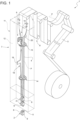
figure 1 is a schematic view of a packaging machine having a package forming apparatus with parts removed for clarity; -
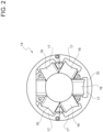
figure 2 is a plan view of a particular of the packaging machine offigure 1 with parts removed for clarity; -
figure 3 is a perspective view of case enclosing a system for setting the spring in a pressing assembly of a tube forming and sealing device realized according to the present invention; -
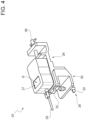
figure 4 is a perspective view of a measuring device realized according to the present invention; -
figure 5 is a perspective view of a sample of the system offigure 3 ; -
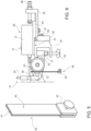
figure 6 and7 are lateral views of the measuring device offigure 4 and of the sample offigure 5 when in use onto the particular offigure 2 . - Number 1 indicates as a whole a packaging machine for producing sealed
packages 2 of a pourable product, in particular a pourable food product, such as milk, milk drinks, yoghurt, yoghurt drinks, fruit juice, wine, tomato sauce, emulsions, beverages containing pulp, salt, sugar, etc. In more detail, packaging machine 1 may be configured to producepackages 2 from a multilayer packaging material. Preferentially, a multilayer packaging material having heat seal properties (i.e. portions of the multilayer packaging material can be sealed to one another). - In further detail, the multilayer packaging material may comprise at least one layer of fibrous material, such as e.g. paper or cardboard, and at least two layers of heat-seal plastic material, e.g. polyethylene, interposing the layer of fibrous material in between one another. Preferentially, one of these two layers of heat-seal plastic material may define the inner face of
packages 2 contacting the pourable product. Moreover, the multilayer packaging material may also comprise a layer of gas- and light-barrier material, e.g. aluminum foil or ethylene vinyl alcohol (EVOH) film, preferentially being arranged between one of the layers of the heat-seal plastic material and the layer of fibrous material. Preferentially, the packaging material may also comprise a further layer of heat-seal plastic material being interposed between the layer of gas- and light-barrier material and the layer of fibrous material. - In further detail, the multilayer packaging material may be provided in the form of a
web 3. - Furthermore, packaging machine 1 is configured to produce
packages 2 by forming a tube 4 from theweb 3, longitudinally sealing the tube 4, filling the tube 4 with the pourable product and to transversally seal, and preferentially transversally cut the tube 4. - According to some possible non-limiting embodiments, each
package 2 extends along a longitudinal axis A and comprises at least a firsttransversal sealing band 5, and preferentially also a second transversal sealing band arranged at opposite ends of thepackage 2. - Moreover, each
package 2 also comprises alongitudinal seam portion 6. Preferentially, each firsttransversal sealing band 5 and/or each second transversal sealing band are transversal (preferentially perpendicular) to the respectivelongitudinal seam portion 6. - With particular reference to
figure 1 , packaging machine 1 comprises apackage forming apparatus 7 configured to at least partially form the tube 4, preferentially to also transversally seal and/or to transversally cut the tube 4, for obtaining thepackages 2. - Moreover, packaging machine 1 comprises:
- a conveying device 8 configured to advance along a conveying path P the
web 3 and the tube 4; - a tube forming and sealing device 9 configured to form the tube 4 from the advancing
web 3 and to longitudinally seal the tube 4; and - a
filling device 10 for filling the tube 4 with the pourable product. - In further detail, the packaging machine 1 comprises an
isolation chamber 11, preferentially delimiting aninner environment 12 from an outer environment. Preferentially, theinner environment 12 is a sterile (aseptic) environment, preferably containing a controlled atmosphere. Preferentially, the tube forming and sealing device 9 is at least partially arranged within theisolation chamber 11, in particular within theinner environment 12, and is configured to fold and longitudinally seal the tube 4 within theisolation chamber 11, in particular within theinner environment 12. - Moreover, the packaging machine 1 comprises a sterilization unit configured to sterilize the advancing
web 3, preferentially the sterilization unit is arranged upstream of the tube forming and sealing device 9 along the conveying path P. - The tube forming and sealing device 9 comprises at least two forming
assemblies isolation chamber 11, even more preferentially arranged within theinner environment 12, configured to gradually fold in cooperation with one another theweb 3 into the tube 4, preferentially by overlapping opposite longitudinal edges of theweb 3 with one another. Thereby, in use, theseam portion 6 is formed. The formingassemblies assemblies assembly 13 and the formingassembly 14 placed along the conveying path P in succession (one after the other) carried by a fixed structure and interacting with theweb 3 of packaging material. - More in detail, the forming
assemblies web 3 of packaging material gradually into the tube 4 (cylinder) and to superimpose a (first) lateral portion 3A of theweb 3 of packaging material to a (second) lateral portion 3B of theweb 3 of packaging material, opposite the (first) lateral portion 3A, to form the continuous tube 4. The formingassembly 14 is placed downstream of the formingassembly 13 along the conveying path P. - The forming
assembly 14 will now be described in detail with particular reference tofigure 2 . The formingassembly 14 comprises a fixed formingring 15 surrounding theweb 3 of packaging material and supporting a number (for example, six) ofrollers 16 cooperating to fold theweb 3 of packaging material. Therollers 16 have respective lateral surfaces with substantial concave shape (i.e. theweb 3 of packaging material encounters a diameter at the ends greater than a diameter at the center of the first rollers 16). The lateral surfaces of therollers 16 define a compulsory passage for theweb 3 of packaging material being folded. Between the formingring 15 and the lateral surfaces of eachrollers 16 are definedrespective gaps 7. - Additionally, the tube forming and sealing device 9 comprises a sealing
device 18 having a sealinghead 19, preferentially arranged within theisolation chamber 11, even more preferentially within theinner environment 11, and, configured to longitudinally seal the tube 4, preferentially along thelongitudinal seam portion 6. Advantageously, the formingassembly 14 is placed downstream of the sealinghead 19 along the conveying path P. In other words, in use, thelongitudinal seam portion 6 is sealed by activation of the sealinghead 18. Preferentially but not necessarily, the sealinghead 19 is at least partially positioned withinisolation chamber 11. - More specifically, the sealing
head 19 is configured to transfer thermal energy to the tube 4, in particular to thelongitudinal seam portion 6 for longitudinally sealing the tube 4. The sealinghead 19 can be of the kind operating by means of induction heating and/or by a stream of a heated gas and/or by means of ultrasound and/or by laser heating and/or by any other means. - Preferentially, the filling
device 10 comprises a fillingpipe 20 configured to direct the pourable product into the tube 4. Preferentially, the fillingpipe 20 is at least partially placed within the tube 4 for continuously feeding, in use, the pourable product into the tube 4. The fillingpipe 20 is in fluid connection with a pourable product storage tank (not shown), which is adapted to store for the pourable product to be packaged. In particular, the fillingpipe 20 is configured to direct, in use, the pourable product into the tube 4. - Finally, the tube forming and sealing device 9 comprises a
pressing assembly 21 configured to exert a mechanical force on the tube 4 during the sealing phase. In particular, the pressing 21 assembly is configured to exert a mechanical force on thelongitudinal seam portion 6 to ensure the longitudinal sealing of the tube 4. Thepressing assembly 21 comprises at least apressure roller 22 and at least acounter-pressure roller 23 adapted to exert the mechanical force onto thelongitudinal seam portion 6 from opposite sides thereof. In particular, in use, thelongitudinal seam portion 6 is interposed between thepressure roller 22 and thecounter-pressure roller 23. Advantageously, thecounter-pressure roller 23 is supported by the formingring 14. - Advantageously, the
pressure roller 22 is supported by the fillingpipe 20. - The
pressure roller 22 is arranged within the tube 4. More in detail, thepressure roller 22 is supported by aspring 24 which is connected to the fillingpipe 20. In particular, thespring 24 may comprise an elastic body, e.g. a bent (metal) plate as depicted in the figures. The elastic body may be configured to recover its original shape when released after being distorted. - The
spring 24 has a first end connected to thepressure roller 22. In particular, thespring 24 has a second end (opposite to the first end) connected to the fillingpipe 20. Preferably, thespring 24 is a (single)leaf spring 24. -
Figures 3 ,4 and5 show asystem 25 for setting thespring 24. In other words, thesystem 25 is configured to set the spring force applied by thespring 24 onto thelongitudinal seam portion 6 to a predetermined value. Advantageously, thesystem 25 is enclosed in a case C. Thesystem 25 is configured for setting thespring 24 during a stop phase of the packaging machine 1 once theweb 3 of packaging material has been removed from the area of thepressing assembly 21. - The
system 25 comprises a measuringdevice 26 configured for measuring the spring force of thespring 24. The measuringdevice 26 comprises aforce gauge 27, in particular adynamometer 27, and anadapter element 28 which is realized to support thedynamometer 27. Preferably, thedynamometer 27 is of the digital type. - The (e.g. digital or analog)
dynamometer 27 comprises a display D for visualizing the measured spring force. Thedynamometer 27 is connected to apin 29 protruding, in use, towards thespring 24. Thepin 29 is configured, in use, to contact thespring 24, e.g. the elastic body thereof. - The
adapter element 28 is connected to a clampingelement 30. The clampingelement 30 is configured to be connected preferably to the formingring 14 or any other support structure arranged in a fixed position with respect to thespring 24. In other words, the clampingelement 30 is realized to be connected in a fixed manner (non-movable and non-releasable manner) to the formingring 15 or to the support structure. - The clamping
element 30 has a substantially C shape with an upper portion having an upperflat surface 31 facing thedynamometer 27 and a lower substantially flat surface which in, use, is arranged in contact with an upper surface of the formingring 15. The clampingelement 30 further comprises anappendage 32 protruding from said lower surface and configured to engage thegap 17. Finally, the clampingelement 30 is provided with fixing means 33 (for example a screw) for tightening the clampingelement 30 onto the formingring 15. - The
adapter element 28 further comprises asupport 34 bracket for thedynamometer 27. Thesupport bracket 34 has a substantially L shape with an upper flat surface for supporting thedynamometer 27 and a lower surface which, in use, slides on theupper surface 31. - Finally, the
adapter element 28 comprises aconnection bracket 35 having a first part configured to be connected to a central part of the clampingelement 30. Said first part is provided with a through slit for adjusting (and regulating) the height of theconnection bracket 35 with respect to the clampingelement 30 by means of fixingmeans 36. In other words, the position of theconnection bracket 35 is adjustable with respect to the clampingelement 30. - The
connection bracket 35 further comprises a (second) part configured to be connected to thesupport bracket 34. The second part has an upper surface upon which, in use, slides thesupport bracket 34. Said second part is provided with a through slit having an oblong shape for enabling connection means 37 to slide within it. Connection means 37 are defined by a nut and a pin fixed to thesupport bracket 34 and protruding downwards from thesupport bracket 34. - Finally, the
connection bracket 35 comprises a (third) part configured to be connected to thesupport bracket 34 by means of aloading device 38. Advantageously, theloading device 38 comprises anendless screw 38. Theendless screw 38 is maneuvered (controlled) by an operator. - In particular, the
loading screw 38 is configured to control the movement of thepin 29 and gradually increase, in use, the force applied by thepin 29 onto thespring 24. The position of the support bracket 34 (and, consequently, of the dynamometer 27) with respect to theconnection bracket 35 is controlled by operating theendless screw 38. Theendless screw 38 is configured to control, in use, the movement of the support bracket 34 (and, consequently, of the dynamometer 27) along a direction Y from a retracted position in which thepin 29 does not contact thespring 24 to an intermediate position in which thepin 29 contacts thespring 24 and to a final position in which it is possible to check a predetermined spring force displayed by thedynamometer 27. - The
system 25 further comprises aload 42 shown in figure. Theload 42 is couplable to a sample (portion) 40 of packaging material to define a sample 39 (i.e. thesample 39 is defined by theload 42 when connected to thesample 40 of packaging material) . Theload 42 ranges from 20 gr to 100 gr; preferably, theload 42 ranges from 40 gr to 75 gr and even more preferably theload 42 is 50 gr. - The
load 42 is configured to be positioned in the area of thespring 24. Advantageously, theload 42 is configured to be positioned at thespring 24, e.g. at the end thereof connected to theroller 22. Theload 42 is configured to exert, in use, a gravitational force indicative of the setting of thespring 24. - Advantageously, the operator thanks to the
load 42 can be able to objectively assess the correct setting of thespring 24. - The
sample 40 of packaging material comprises a first semi-portion of material that overlaps a second portion of material defining an overlappingregion 41. Preferably, theload 42 can be coupled to thesample 40 of packaging material in a releasable manner in order to substitute the attachedsample 40 of packaging material. - Preferably, the overlapping
region 41 has a thickness that is substantially equal to 1 mm. More in detail, thesample 40 of packaging material is configured to reproduce thelongitudinal seam portion 6 of the tube 4. Thesample 40 of packaging material is realized to be interposed, in use, between thepressure roller 22 and thecounter-pressure roller 23. Advantageously, thesample 40 of packaging material may not be part of thesystem 25.Different samples 40 of packaging material can be connected to theload 42. - More in detail, as already said, the
endless screw 38 is configured to control, in use, the movement of the support bracket 34 (and, consequently, of the dynamometer 27) along the direction Y to the final position which corresponds a predetermined spring force displayed in the display D. - The method to measure the spring force of the
spring 24 by means of thesystem 25 comprises the following: - optionally, a preliminary phase of regulating the position (i.e., the height) of the
connection bracket 35 with respect to the clampingelement 30 through the fixing means 36; - connecting the
adapter element 28 to the formingassembly 14; in detail, the clampingelement 30 is connected to the formingring 15 by inserting theappendage 32 into thegap 17 and by tightening the fixing means 33; - measuring the spring force, e.g. by means of the display D of the
dynamometer 27; - adjusting the position of the pin 29as a function of the measured spring force; and
- reaching a predetermined force.
- The method may comprise one or more of:
- a phase in which the
dynamometer 27 is turned on and settled to zero Newton; - a phase in which the operator starts to slightly move the
endless screw 38 thereby causing the movement of thedynamometer 27 from the retracted position in which thepin 29 does not contact thespring 24 to an intermediate position in which thepin 29 contacts thespring 24; when thepin 29 contacts thespring 24, the measured spring force begin to rise and is readable in the display D. - By slightly moving the
endless screw 38, the measured spring force visible in the display D continuously increases and thepin 29 begins to slightly move thepressure roller 22 away from thecounter-pressure roller 23. - The method for setting the
spring 24 by means of thesystem 25 may further comprise one or more of the following: - coupling the
portion 40 of packaging material to theload 42 and, subsequently, arranging theportion 40 of packaging material between thepressure roller 22 and thecounter-pressure roller 23 with theload 42 positioned closer to the ground with respect to theportion 40 of packaging material; and - checking the force shown by the
dynamometer 27 when thesample 40 of packaging material starts moving due to the gravitational force of theload 42. - In other words, the last step may be written as checking whether the
sample 39 falls when the predetermined force is readable in the display D. - In other words, when the predetermined force is readable in the display D the
sample 39 should start to move/fall. - Finally, if the
sample 39 falls before thedynamometer 27 displays the predetermined force or if thesample 39 does not fall when thedynamometer 27 displays the predetermined force a bend of thespring 24 has to be adjusted. - The
system 25 described above has multiple advantages; in particular, it has been demonstrated that the measured spring force is more precise and accurate, and the procedure is more repeatable and less operator dependent. Moreover, theadapter element 28 can be easily installed on many different formingassemblies 14. -
- 1
- packaging machine
- 2
- packages
- 3
- web of packaging material
- 4
- tube
- 5
- sealing band
- 6
- longitudinal seam portion
- 7
- package forming apparatus
- 8
- conveying device
- 9
- tube forming and sealing device
- 10
- filling device
- 11
- isolation chamber
- 12
- inner environment
- 13
- forming assembly
- 14
- forming assembly
- 15
- forming ring
- 16
- roller
- 17
- gap
- 18
- sealing device
- 19
- sealing head
- 20
- filling pipe
- 21
- pressing assembly
- 22
- pressure roller
- 23
- counter pressure roller
- 24
- spring
- 25
- system
- 26
- measuring device
- 27
- dynamometer
- 28
- adapter element
- 29
- pin
- 30
- clamping element
- 31
- upper surface
- 32
- appendage
- 33
- fixing means
- 34
- support bracket
- 35
- connection bracket
- 36
- fixing means
- 37
- connection means
- 38
- loading element/screw
- 39
- sample
- 40
- sample of packaging material
- 41
- overlapping region
- 42
- load
- P
- conveying path
- D
- display
- C
- case
- Y
- direction
Claims (16)
- A measuring device (26) for measuring a spring force of a spring (24) in a pressing assembly (21) of a tube forming and sealing device (9), the measuring device (26) comprising:- a force gauge (27), in particular a dynamometer (27), for measuring the spring force and provided with a pin (29) configured, in use, to contact the spring (24);- an adapter element (28) comprising a loading device (38) configured to control a movement of the pin (29) and gradually increase, in use, the force applied by the pin (29) to the spring (24), and- a clamping element (30), preferably with a substantially C shape, couplable in use to a support structure arranged in a fixed position with respect to the spring (24).
- A measuring device (26) according to claim 1, wherein the support structure comprises a fixed forming ring (15) supporting a number of rollers (16) configured to cooperate to fold a web (3) of packaging material and wherein between the forming ring (15) and the lateral surfaces of each roller (16) are defined respective gaps (17); the clamping element (30) comprises an appendage (32) configured to engage, in use, one of said gap (17).
- - A measuring device (26) according to claim 1 or 2, wherein the adapter element (28) comprises a connection bracket (35) having a first part configured to be connected to the clamping element (30), wherein the position of said connection bracket (35) is adjustable with respect to the clamping element (30).
- - A measuring device (26) according to claim 3, wherein the connection bracket (35) is provided with a through slit for adjusting its height with respect to the clamping element (30) by means of fixing means (36).
- - A measuring device (26) according to any previous claim, wherein the clamping element (30) comprises an upper surface (31) and wherein the adapter element (28) comprises a support bracket (34) for supporting the force gauge (27), the adapter element (28) having a lower surface which, in use, slides on the upper surface (31) along a direction (Y).
- - A measuring device (26) according to any claim 5, wherein the adapter element (28) comprises a connection bracket (35) provided with a through slit having an oblong shape for enabling connection means (37) to slide within it; connection means (37) are at least partly fixed to the support bracket (34).
- A measuring device (26) according to any previous claim, wherein the loading device (38) comprises an endless screw (38) and wherein the movement of the pin (29) is obtained by turning said endless screw (38).
- A system for setting a spring (24) in a pressing assembly (21) of a tube forming and sealing device (9) comprising:- a measuring device (26) according to anyone of the previous claims; and- a load (42) configured to be positioned at the spring (24) and to exert a gravitational force indicative of the setting of the spring (24).
- A system according to claim 8, wherein the load (42) is couplable to a sample (40) of packaging material wherein a first semi-portion of material overlaps a second portion of material defining an overlapping region (41) to reproduce a longitudinal seam portion (6) of a tube (4) of packaging material.
- A system according to claim 8 or 9, wherein the load (42) is couplable to a sample (40) of packaging material having a thickness of substantially 1 mm.
- A system according to claim 9 or 10, wherein the support structure comprises a fixed forming ring (15) surrounding a web (3) of packaging material and the pressing assembly (21) comprises a pressure roller (22) positioned at an end of the spring (24) and a counter pressure roller (23) arranged on the forming ring (15); the sample (40) of packaging material being configured to be interposed, in use, between the pressure roller (22) and the counter pressure roller (23).
- A system according to claim 11, wherein the load (42) is configured to cause a disengagement of the sample (40) of packaging material from the pressure roller (22) and the counter pressure roller (23).
- - A method for measuring a spring force of a spring (24) in a pressing assembly (21) of a tube forming and sealing device (9) comprising a forming assembly (14) to gradually fold a web (3) of packaging material into a tube (4) and arranged in a fixed position with respect to the spring (24); the method comprises the steps of:- providing a measuring device (26) according to any of claims 1 to 7;- connecting the clamping element (30), preferably with a substantially C shape, to the support structure;- measuring the spring force;- adjusting a position of the pin (29) as a function of the measured spring force;- reaching a predetermined force.
- A method according to claim 13, comprising adjusting the pin (29) position by screwing an endless screw (38).
- A method for setting a spring (24) in a pressing assembly (21) of a tube forming and sealing device (9) comprising the method steps according to claim 13 or claim 14 and the further steps of:- coupling a sample (40) of packaging material to a load (42);- positioning the sample (40) of packaging material between a pressure roller (22) of the pressing assembly (21) connected to an end of the spring (24) and a counter pressure roller (23) of the pressing assembly (21) connected to the forming assembly (14); wherein the load (42) is positioned closer to the ground with respect to the sample (40) of packaging material;- checking the force shown by the dynamometer (27) when the sample (40) of packaging material starts moving due to the gravitational force of the load (42).
- A method according to claim 15 and comprising the further step of adjusting a bend of the spring (24) if the sample (40) of packaging material starts moving before the force gauge (27) displays the predetermined force or if the sample (40) of packaging material does not move when the force gauge (27) displays the predetermined force.
Applications Claiming Priority (1)
| Application Number | Priority Date | Filing Date | Title |
|---|---|---|---|
| IT102023000025596A IT202300025596A1 (en) | 2023-11-30 | 2023-11-30 | A DEVICE FOR MEASURING THE FORCE OF A SPRING IN A PRESSING GROUP OF A DEVICE FOR FORMING AND SEALING A TUBE, A SYSTEM FOR ADJUSTING SAID SPRING, A METHOD FOR MEASURING THE FORCE OF SAID SPRING AND A METHOD FOR ADJUSTING SAID SPRING |
Publications (1)
| Publication Number | Publication Date |
|---|---|
| EP4563960A1 true EP4563960A1 (en) | 2025-06-04 |
Family
ID=89663375
Family Applications (1)
| Application Number | Title | Priority Date | Filing Date |
|---|---|---|---|
| EP24214059.8A Pending EP4563960A1 (en) | 2023-11-30 | 2024-11-20 | Measuring device and method for measuring a spring force |
Country Status (3)
| Country | Link |
|---|---|
| EP (1) | EP4563960A1 (en) |
| IT (1) | IT202300025596A1 (en) |
| WO (1) | WO2025114096A1 (en) |
Citations (1)
| Publication number | Priority date | Publication date | Assignee | Title |
|---|---|---|---|---|
| EP2143643A1 (en) * | 2008-07-11 | 2010-01-13 | Tetra Laval Holdings & Finance SA | Packaging machine for producing sealed packages of a food product |
-
2023
- 2023-11-30 IT IT102023000025596A patent/IT202300025596A1/en unknown
-
2024
- 2024-11-20 EP EP24214059.8A patent/EP4563960A1/en active Pending
- 2024-11-20 WO PCT/EP2024/082907 patent/WO2025114096A1/en active Pending
Patent Citations (1)
| Publication number | Priority date | Publication date | Assignee | Title |
|---|---|---|---|---|
| EP2143643A1 (en) * | 2008-07-11 | 2010-01-13 | Tetra Laval Holdings & Finance SA | Packaging machine for producing sealed packages of a food product |
Non-Patent Citations (1)
| Title |
|---|
| RIZZELLO GIANLUCA ET AL: "Towards Sensorless Soft Robotics: Self-Sensing Stiffness Control of Dielectric Elastomer Actuators", IEEE TRANSACTIONS ON ROBOTICS, IEEE SERVICE CENTER, PISCATAWAY, NJ, US, vol. 36, no. 1, 1 February 2020 (2020-02-01), pages 174 - 188, XP011770937, ISSN: 1552-3098, [retrieved on 20200205], DOI: 10.1109/TRO.2019.2944592 * |
Also Published As
| Publication number | Publication date |
|---|---|
| IT202300025596A1 (en) | 2025-05-30 |
| WO2025114096A1 (en) | 2025-06-05 |
Similar Documents
| Publication | Publication Date | Title |
|---|---|---|
| EP3438007B1 (en) | A method and an apparatus for applying a sealing strip to a web of packaging material | |
| EP2143643A1 (en) | Packaging machine for producing sealed packages of a food product | |
| CN102216054B (en) | Apparatus and method for detecting the position of a sealing strip applied to a web of food packaging material | |
| US11104462B2 (en) | Guiding device | |
| US5220771A (en) | Tetrahedron volume control | |
| US10399724B2 (en) | Packaging machine and method for producing packages from a packaging material | |
| WO2025114096A1 (en) | A measuring device for measuring a spring force of a spring in a pressing assembly of a tube forming and sealing device, a system for setting said spring, a method for measuring the spring force of said spring and a method for setting said spring | |
| WO2010011168A1 (en) | Means and method to provide embossments on packaging containers | |
| EP4588648A1 (en) | Apparatus and method for applying a sealing strip of a heat-sealable material to a web of packaging material, packaging machine for forming sealed packages | |
| EP4588646A1 (en) | Apparatus for applying a sealing strip of a heat-sealable material to a web of packaging material and packaging machine for forming sealed packages | |
| EP4357256B1 (en) | Package forming apparatus for a packaging machine and packaging machine for forming packages filled with a pourable product | |
| EP4410691B1 (en) | Package forming apparatus for a packaging machine and packaging machine for forming packages filled with a pourable product | |
| EP4606749A1 (en) | Splicing unit for splicing a sealing strip of heat-sealable material, apparatus for applying a sealing strip to a web of packaging material and packaging machine for forming sealed packages | |
| EP4549329A1 (en) | Package forming apparatus for a packaging machine and packaging machine for forming packages filled with a pourable product | |
| EP4410690B1 (en) | Package forming apparatus for a packaging machine and packaging machine for forming packages filled with a pourable product | |
| EP4410522A1 (en) | Package forming apparatus for a packaging machine and packaging machine for forming packages filled with a pourable product | |
| CN203581459U (en) | Positioning device used for positioning sealing strip and packing machine | |
| WO2025078054A1 (en) | Inspection apparatus for a capping apparatus, capping apparatus having an inspection apparatus, packaging machine, method of inspecting caps and method of applying caps | |
| JP2017019544A (en) | Ultrasonic wave seal method and device | |
| HK1163020A (en) | Apparatus and method for detecting the position of application of a sealing strip onto a web of packaging material for food products |
Legal Events
| Date | Code | Title | Description |
|---|---|---|---|
| PUAI | Public reference made under article 153(3) epc to a published international application that has entered the european phase |
Free format text: ORIGINAL CODE: 0009012 |
|
| STAA | Information on the status of an ep patent application or granted ep patent |
Free format text: STATUS: THE APPLICATION HAS BEEN PUBLISHED |
|
| AK | Designated contracting states |
Kind code of ref document: A1 Designated state(s): AL AT BE BG CH CY CZ DE DK EE ES FI FR GB GR HR HU IE IS IT LI LT LU LV MC ME MK MT NL NO PL PT RO RS SE SI SK SM TR |
|
| STAA | Information on the status of an ep patent application or granted ep patent |
Free format text: STATUS: REQUEST FOR EXAMINATION WAS MADE |
|
| 17P | Request for examination filed |
Effective date: 20251204 |