EP4563945A1 - Terrain database adaptive resolution method - Google Patents
Terrain database adaptive resolution method Download PDFInfo
- Publication number
- EP4563945A1 EP4563945A1 EP24216290.7A EP24216290A EP4563945A1 EP 4563945 A1 EP4563945 A1 EP 4563945A1 EP 24216290 A EP24216290 A EP 24216290A EP 4563945 A1 EP4563945 A1 EP 4563945A1
- Authority
- EP
- European Patent Office
- Prior art keywords
- terrain
- elevation
- database
- tiles
- obstacle
- Prior art date
- Legal status (The legal status is an assumption and is not a legal conclusion. Google has not performed a legal analysis and makes no representation as to the accuracy of the status listed.)
- Pending
Links
Images


Classifications
-
- G—PHYSICS
- G01—MEASURING; TESTING
- G01C—MEASURING DISTANCES, LEVELS OR BEARINGS; SURVEYING; NAVIGATION; GYROSCOPIC INSTRUMENTS; PHOTOGRAMMETRY OR VIDEOGRAMMETRY
- G01C23/00—Combined instruments indicating more than one navigational value, e.g. for aircraft; Combined measuring devices for measuring two or more variables of movement, e.g. distance, speed or acceleration
-
- G—PHYSICS
- G01—MEASURING; TESTING
- G01C—MEASURING DISTANCES, LEVELS OR BEARINGS; SURVEYING; NAVIGATION; GYROSCOPIC INSTRUMENTS; PHOTOGRAMMETRY OR VIDEOGRAMMETRY
- G01C21/00—Navigation; Navigational instruments not provided for in groups G01C1/00 - G01C19/00
- G01C21/38—Electronic maps specially adapted for navigation; Updating thereof
- G01C21/3804—Creation or updating of map data
-
- G—PHYSICS
- G06—COMPUTING OR CALCULATING; COUNTING
- G06F—ELECTRIC DIGITAL DATA PROCESSING
- G06F16/00—Information retrieval; Database structures therefor; File system structures therefor
- G06F16/20—Information retrieval; Database structures therefor; File system structures therefor of structured data, e.g. relational data
- G06F16/23—Updating
-
- G—PHYSICS
- G06—COMPUTING OR CALCULATING; COUNTING
- G06F—ELECTRIC DIGITAL DATA PROCESSING
- G06F16/00—Information retrieval; Database structures therefor; File system structures therefor
- G06F16/20—Information retrieval; Database structures therefor; File system structures therefor of structured data, e.g. relational data
- G06F16/29—Geographical information databases
-
- G—PHYSICS
- G08—SIGNALLING
- G08G—TRAFFIC CONTROL SYSTEMS
- G08G5/00—Traffic control systems for aircraft
- G08G5/70—Arrangements for monitoring traffic-related situations or conditions
- G08G5/74—Arrangements for monitoring traffic-related situations or conditions for monitoring terrain
-
- G—PHYSICS
- G08—SIGNALLING
- G08G—TRAFFIC CONTROL SYSTEMS
- G08G5/00—Traffic control systems for aircraft
- G08G5/80—Anti-collision systems
Definitions
- Terrain databases consists of an evenly-gridded set of elevation posts (tiles). Terrain databases are organized collections of equally spaced tiles to cover the earth (or some subset). Each tile has a four-corner boundary with some associated parameters such as altitude and terrain or Water.
- Terrain source databases come in various resolutions. Terrain tile size depends on the resolution of the database. The higher the resolution of the database, the smaller is the tile Size and vice-versa.
- avionics applications utilize a high-resolution terrain database to provide the pilot the overall awareness of the aircraft, its physical location in space, and all terrain relating to the safety of the flight.
- Situational awareness databases are created by civil aviation authorities or public entities using one or more sources. Multiple sources may generate some accuracy and incorrect altitude issues in the database release.
- Database cells often include inaccurate altitudes near the approach path to the runway due to insufficient resolution and data sensor issues such as highly reflective surfaces. There may be some difference between the database cell altitude and aircraft sensor data altitude. Also, extra guard bands may be added by applications when there is low data accuracy, or no accuracy information is present. Vertical and horizontal accuracy attributes capture reported source accuracy in the database when specified. In many cases the source providers do not specify vertical and horizontal accuracy information causing the application to add excessive guard to the existing obstacle height and width.
- Each terrain database cell (single elevation post) has elevation; each Obstacle database cell (single elevation post) has elevation and accuracy information.
- Each cell has both horizontal accuracy (width) and vertical accuracy (height) encoded by the supplier. In many cases, the source providers do not specify vertical and horizontal accuracy information.
- the system provides a computer apparatus, a system and method as defined by the claims, for improving the resolution and accuracy of avionics databases with limited impact on the size of the database.
- the system identifies tiles including runway approaches and incorporates higher resolution tiles for those regions.
- the system may also identify tiles including high terrain variability. Those regions may also include higher resolution tiles.
- inventive concepts are not limited in their application to the arrangement of the components or steps or methodologies set forth in the following description or illustrated in the drawings.
- inventive concepts disclosed herein may be practiced without these specific details.
- well-known features may not be described in detail to avoid unnecessarily complicating the instant disclosure.
- inventive concepts disclosed herein are capable of other embodiments or of being practiced or carried out in various ways. Also, it is to be understood that the phraseology and terminology employed herein is for the purpose of description and should not be regarded as limiting.
- any reference to "one embodiment,” or “some embodiments” means that a particular element, feature, structure, or characteristic described in connection with the embodiment is included in at least one embodiment of the inventive concepts disclosed herein.
- the appearances of the phrase “in at least one embodiment” in the specification does not necessarily refer to the same embodiment.
- Embodiments of the inventive concepts disclosed may include one or more of the features expressly described or inherently present herein, or any combination or sub-combination of two or more such features.
- embodiments of the inventive concepts disclosed herein are directed to a system and method for improving the resolution and accuracy of avionics databases with limited impact on the size of the database.
- the system identifies tiles including runway approaches and incorporates higher resolution tiles for those regions.
- the system may also identify tiles including high terrain variability. Those regions may also include higher resolution tiles.
- the system may identify multiple tiles that each define the same elevation and / or terrain variability. Those tiles may be consolidated into a single lower resolution tile.
- Aircraft may record elevations via onboard sensors. Multiple sensor samples may be combined and applied to an existing database to constrain the database accuracy.
- FIG. 1 a block diagram of a system according to an exemplary embodiment is shown.
- a majority of nuisance terrain alerts occur when an aircraft is near to a runway at lower altitudes. It is desirable to reduce any sources of error that lead to such nuisance alerts.
- a computer system 100 including at least one processor configured via non-transitory processor executable code, is in data communication with a plurality of data sources 102, 104, 106 and a plurality of onboard flight sensors 112 or a data source including previously recorded data from a plurality of onboard sensors 112.
- the data from the plurality of on-board sensors may include data from multiple independent flights, including flights from different aircraft, at different times, and with different onboard sensors. Any sensors can be utilized that further define resolution and resolve accuracy.
- Sensors 112 may include GPS, radio altimeter, pressure altitude, or the like, as well as basic air data.
- the system 100 receives terrain data from a terrain database 102, obstacle data from an obstacle database 104, and airport / runway data from an airport database 106.
- the system 100 validates the terrain database 102 and obstacle database 104 under the approach path.
- the system 100 correlates the sensor data against the terrain database 102 and obstacle database 104 cell.
- data analysis techniques can be applied looking for anomalies in the terrain and obstacle data. These anomalies can then be addressed directly in the databases 102, 104.
- the system 100 utilizes machine learning such as neural networks. Alternatively, or in addition, algorithmic analysis may be applied.
- the system 100 may sub-divide the existing database elevation tile into smaller elevation tiles providing better database accuracy and higher adaptive resolution.
- the system 100 may define a threshold deviation; when the flight sensor data for a portion of the tile deviates from the tile by more than the threshold deviation, the system 100 may begin the process of subdividing the tile; if the flight sensor data for that portion never exceeds the threshold deviation, then the tile may remain intact.
- the system 100 may analyze flight sensor data across multiple tiles. The system 100 may determine that multiple adjacent tiles each indicate the same or similar altitude. Those tiles may be consolidated into a single tile. In at least one embodiment, the system 100 may specifically identify four tile blocks that may be combined into a single tile (within the constraints of a tile mapping to the globe). In at least one embodiment, the system 100 may define a maximum threshold deviation when consolidating tiles; tiles with a greater elevation deviation than the maximum threshold deviation are not consolidated. Consolidation allows the overall terrain database 102 to remain consistent over regions proximal to airports or airport runways include higher resolution tiles.
- the system 100 validates the terrain data under the approach path. Using flight data collected from the onboard sensors 112, the system 100 correlates the sensor data against the terrain database 102. Once multiple approaches are captured for a given runway, data analysis techniques can be applied looking for anomalies in the terrain data. These anomalies can then be addressed directly in the terrain database 102. In at least one embodiment, the system utilizes machine learning such as neural networks. Alternatively, or in addition, algorithmic analysis may be applied.
- Embodiments of the present disclosure correct the altitude mismatch and improve the accuracy of the database.
- the system 100 produces a terrain database 108 with corrected altitude data near airports, and an obstacle database 110 with corrected altitude and accuracy data.
- the system 100 may constrain the accuracy of data based on the onboard sensors compiled from multiple flights / multiple sources. That is to say, the system 100 may maintain altitude data within the terrain database 108 and obstacle database 110, but add or update constraints to any uncertainty about those altitudes.
- a computer apparatus executing the method may select 200 an airport / runway and access 202 all terrain elevation tiles within some predetermined distance of that airport / runway. The computer apparatus may then sub-divide the terrain elevation tiles and determine new elevations for the newly created tiles with reference to stored terrain data.
- the computer apparatus may determine 206 if there is a mismatch between onboard flight sensor data and the elevation assigned to each newly created tile; flight sensor data may be compiled and correlated over a plurality of flights. If there is no mismatch, or any discrepancy is within some predetermined threshold, then computer apparatus processes 208 the new tiles to generate 210 a high-resolution portion of the database. If the computer apparatus determines 206 that a mismatch does exist, the computer apparatus may replace 212 elevations in the terrain database with the compiled and correlated sensor data for the corresponding tiles.
- the computer apparatus may merge 214 symmetrical, adjacent tiles with the same elevation value to create one lower resolution tile where higher resolution data is unnecessary. It may be appreciated that tiles may be merged where the number and disposition of the tiles is conducive to create one single tile.
- a computer apparatus executing the method may select 300 an airport / runway and access 302 all terrain and obstacle elevation tiles within some predetermined distance of that airport / runway.
- the computer apparatus may determine 304 if there is a mismatch between onboard flight sensor data and the elevation assigned to each tile; flight sensor data may be compiled and correlated over a plurality of flights. If there is no mismatch, or any discrepancy is within some predetermined threshold, then computer apparatus produces 306 a production database.
- the computer apparatus may determine 310 if the mismatch is in the terrain database or the obstacle database. If the mismatch is in the terrain database, the computer apparatus replaces 308 the elevation value in the corresponding tile with the elevation value determined via the onboard flight sensor data.
- the elevation value determined via the onboard flight sensor data may be an average value determined over a plurality of flights, a weighted value according to the known accuracy of the corresponding sensor, a value from the known most accurate sensor constrained by other flight sensor data, or some other such methodology.
- the computer apparatus replaces 312 the elevation value in the corresponding tile with the elevation value determined via the onboard flight sensor data and updates the accuracy attribute (including adding an accuracy attribute where none currently exists).
- the accuracy attribute may be defined by the range of flight sensor data values.
- the computer apparatus produces 306 the appropriate databases.
- the computer apparatus may embody in a trained artificial intelligence such as a trained neural network.
- the neural network 400 comprises an input layer 402, and output layer 404, and a plurality of internal layers 406, 408. Each layer comprises a plurality of neurons or nodes 410, 436, 438, 440.
- each node 410 receives one or more inputs 418, 420, 422, 424 corresponding to a digital signal and produces an output 412 based on an activation function unique to each node 410 in the input layer 402.
- An activation function may be a Hyperbolic tangent function, a linear output function, and / or a logistic function, or some combination thereof, and different nodes 410, 436, 438, 440 may utilize different types of activation functions.
- such activation function comprises the sum of each input multiplied by a synaptic weight.
- the output 412 may comprise a real value with a defined range or a Boolean value if the activation function surpasses a defined threshold. Such ranges and thresholds may be defined during a training process. Furthermore, the synaptic weights are determined during the training process.
- Outputs 412 from each of the nodes 410 in the input layer 402 are passed to each node 436 in a first intermediate layer 406.
- the process continues through any number of intermediate layers 406, 408 with each intermediate layer node 436, 438 having a unique set of synaptic weights corresponding to each input 412, 414 from the previous intermediate layer 406, 408.
- certain intermediate layer nodes 436, 438 may produce a real value with a range while other intermediated layer nodes 436, 438 may produce a Boolean value.
- certain intermediate layer nodes 436, 438 may utilize a weighted input summation methodology while others utilize a weighted input product methodology.
- synaptic weight may correspond to bit shifting of the corresponding inputs 412, 414, 416.
- An output layer 404 including one or more output nodes 440 receives the outputs 416 from each of the nodes 438 in the previous intermediate layer 408. Each output node 440 produces a final output 426, 428, 430, 432, 434 via processing the previous layer inputs 416. Such outputs may comprise separate components of an interleaved input signal, bits for delivery to a register, or other digital output based on an input signal and DSP algorithm.
- each node 410, 436, 438, 440 in any layer 402, 406, 408, 404 may include a node weight to boost the output value of that node 410, 436, 438, 440 independent of the weighting applied to the output of that node 410, 436, 438, 440 in subsequent layers 404, 406, 408. It may be appreciated that certain synaptic weights may be zero to effectively isolate a node 410, 436, 438, 440 from an input 412, 414, 416, from one or more nodes 410, 436, 438 in a previous layer, or an initial input 418, 420, 422, 424.
- the number of processing layers 402, 404, 406, 408 may be constrained at a design phase based on a desired data throughput rate. Furthermore, multiple processors and multiple processing threads may facilitate simultaneous calculations of nodes 410, 436, 438, 440 within each processing layers 402, 404, 406, 408.
- Layers 402, 404, 406, 408 may be organized in a feed forward architecture where nodes 410, 436, 438, 440 only receive inputs from the previous layer 402, 404, 406 and deliver outputs only to the immediately subsequent layer 404, 406, 408, or a recurrent architecture, or some combination thereof.
- a trained neural network may receive terrain data from one or more terrain and obstacle databases as input, and identify tiles to be broken up for greater granularity. Furthermore, the neural network may be trained to identify tiles to be combined based on elevation data within some threshold consistency.
- Embodiments of the present disclosure create adaptively greater resolution near an area of interest such as a runway.
- the system may consolidate areas that do not need great resolution (e.g., flat, featureless areas) into larger tiles; reducing the overall size of the database.
- embodiments of the present disclosure refine elevation values in existing databases based on actually flight sensor data compiled over time. Flight sensor data may be used to establish accuracy metrics even when the elevation values remain unchanged.
Landscapes
- Engineering & Computer Science (AREA)
- Physics & Mathematics (AREA)
- General Physics & Mathematics (AREA)
- Theoretical Computer Science (AREA)
- Remote Sensing (AREA)
- Databases & Information Systems (AREA)
- Radar, Positioning & Navigation (AREA)
- Data Mining & Analysis (AREA)
- General Engineering & Computer Science (AREA)
- Aviation & Aerospace Engineering (AREA)
- Automation & Control Theory (AREA)
- Traffic Control Systems (AREA)
Abstract
A system and method for improving the resolution and accuracy of avionics databases with limited impact on the size of the database includes identifying tiles including runway approaches and incorporates higher resolution tiles for those regions. The system may also identify tiles including high terrain variability. Those regions may also include higher resolution tiles. The system may identify multiple tiles that each define the same elevation and / or terrain variability. Those tiles may be consolidated into a single lower resolution tile. Aircraft may record elevations via onboard sensors. Multiple sensor samples may be combined and applied to an existing database to constrain the database accuracy.
Description
- Terrain databases consists of an evenly-gridded set of elevation posts (tiles). Terrain databases are organized collections of equally spaced tiles to cover the earth (or some subset). Each tile has a four-corner boundary with some associated parameters such as altitude and terrain or Water.
- Terrain source databases come in various resolutions. Terrain tile size depends on the resolution of the database. The higher the resolution of the database, the smaller is the tile Size and vice-versa.
- Geographic reference systems treat the globe as if it were a sphere divided into 360 equal parts called degrees. Each degree is subdivided into 60 minutes. Each minute is composed of 60 seconds. An arc-second represents the distance of latitude or longitude traversed on the earth's surface while traveling one second (1/3600th of a degree). At the equator, an arc-second of longitude approximately equals an arc-second of latitude, which is 1/60th of a nautical mile (101.27 feet / 30.87 meters). Arc-seconds of latitude remain nearly constant, while arcseconds of longitude decrease in a trigonometric cosine-based fashion as one moves toward the earth's poles. Also, tiles generally ignore the curvature of the earth and uneven terrain within a given tile. Higher resolution databases have better database accuracy but take up more storage space and processing speed is slow.
- Furthermore, avionics applications utilize a high-resolution terrain database to provide the pilot the overall awareness of the aircraft, its physical location in space, and all terrain relating to the safety of the flight. Situational awareness databases are created by civil aviation authorities or public entities using one or more sources. Multiple sources may generate some accuracy and incorrect altitude issues in the database release.
- Database cells often include inaccurate altitudes near the approach path to the runway due to insufficient resolution and data sensor issues such as highly reflective surfaces. There may be some difference between the database cell altitude and aircraft sensor data altitude. Also, extra guard bands may be added by applications when there is low data accuracy, or no accuracy information is present. Vertical and horizontal accuracy attributes capture reported source accuracy in the database when specified. In many cases the source providers do not specify vertical and horizontal accuracy information causing the application to add excessive guard to the existing obstacle height and width.
- Each terrain database cell (single elevation post) has elevation; each Obstacle database cell (single elevation post) has elevation and accuracy information. Each cell has both horizontal accuracy (width) and vertical accuracy (height) encoded by the supplier. In many cases, the source providers do not specify vertical and horizontal accuracy information.
- to the invention provides a computer apparatus, a system and method as defined by the claims, for improving the resolution and accuracy of avionics databases with limited impact on the size of the database. The system identifies tiles including runway approaches and incorporates higher resolution tiles for those regions.
- In embodiments, the system may also identify tiles including high terrain variability. Those regions may also include higher resolution tiles.
- In embodiments, the system may identify multiple tiles that each define the same elevation and / or terrain variability. Those tiles may be consolidated into a single lower resolution tile.
- In embodiments, aircraft may record elevations via onboard sensors. Multiple sensor samples may be combined and applied to an existing database to constrain the database accuracy.
- It is to be understood that both the foregoing general description and the following detailed description are exemplary and explanatory only and should not restrict the scope of the claims. The accompanying drawings, which are incorporated in and constitute a part of the specification, illustrate exemplary embodiments of the inventive concepts disclosed herein and together with the general description, serve to explain the principles.
- The numerous advantages of the embodiments of the inventive concepts disclosed herein may be better understood by those skilled in the art by reference to the accompanying figures in which:
-
FIG. 1 shows a block diagram of a system according to an exemplary embodiment; -
FIG. 2 shows a flowchart of a method according to an exemplary embodiment; -
FIG. 3 shows a flowchart of a method according to an exemplary embodiment; and -
FIG. 4 shows a block diagram of a neural network according an exemplary embodiment of the inventive concepts disclosed herein; - Before explaining various embodiments of the inventive concepts disclosed herein in detail, it is to be understood that the inventive concepts are not limited in their application to the arrangement of the components or steps or methodologies set forth in the following description or illustrated in the drawings. In the following detailed description of embodiments of the instant inventive concepts, numerous specific details are set forth in order to provide a more thorough understanding of the inventive concepts. However, it will be apparent to one of ordinary skill in the art having the benefit of the instant disclosure that the inventive concepts disclosed herein may be practiced without these specific details. In other instances, well-known features may not be described in detail to avoid unnecessarily complicating the instant disclosure. The inventive concepts disclosed herein are capable of other embodiments or of being practiced or carried out in various ways. Also, it is to be understood that the phraseology and terminology employed herein is for the purpose of description and should not be regarded as limiting.
- As used herein a letter following a reference numeral is intended to reference an embodiment of a feature or element that may be similar, but not necessarily identical, to a previously described element or feature bearing the same reference numeral (e.g., 1, 1a, 1b). Such shorthand notations are used for purposes of convenience only, and should not be construed to limit the inventive concepts disclosed herein in any way unless expressly stated to the contrary.
- Further, unless expressly stated to the contrary, "or" refers to an inclusive or and not to an exclusive or. For example, a condition A or B is satisfied by anyone of the following: A is true (or present) and B is false (or not present), A is false (or not present) and B is true (or present), and both A and B are true (or present).
- In addition, use of "a" or "an" are employed to describe elements and components of embodiments of the instant inventive concepts. This is done merely for convenience and to give a general sense of the inventive concepts, and "a" and "an" are intended to include one or at least one and the singular also includes the plural unless it is obvious that it is meant otherwise.
- Also, while various components may be depicted as being connected directly, direct connection is not a requirement. Components may be in data communication with intervening components that are not illustrated or described.
- Finally, as used herein any reference to "one embodiment," or "some embodiments" means that a particular element, feature, structure, or characteristic described in connection with the embodiment is included in at least one embodiment of the inventive concepts disclosed herein. The appearances of the phrase "in at least one embodiment" in the specification does not necessarily refer to the same embodiment. Embodiments of the inventive concepts disclosed may include one or more of the features expressly described or inherently present herein, or any combination or sub-combination of two or more such features.
- Broadly, embodiments of the inventive concepts disclosed herein are directed to a system and method for improving the resolution and accuracy of avionics databases with limited impact on the size of the database. The system identifies tiles including runway approaches and incorporates higher resolution tiles for those regions. The system may also identify tiles including high terrain variability. Those regions may also include higher resolution tiles. The system may identify multiple tiles that each define the same elevation and / or terrain variability. Those tiles may be consolidated into a single lower resolution tile. Aircraft may record elevations via onboard sensors. Multiple sensor samples may be combined and applied to an existing database to constrain the database accuracy.
- Referring to
FIG. 1 , a block diagram of a system according to an exemplary embodiment is shown. A majority of nuisance terrain alerts occur when an aircraft is near to a runway at lower altitudes. It is desirable to reduce any sources of error that lead to such nuisance alerts. - A
computer system 100, including at least one processor configured via non-transitory processor executable code, is in data communication with a plurality ofdata sources onboard flight sensors 112 or a data source including previously recorded data from a plurality ofonboard sensors 112. It may be appreciated that the data from the plurality of on-board sensors may include data from multiple independent flights, including flights from different aircraft, at different times, and with different onboard sensors. Any sensors can be utilized that further define resolution and resolve accuracy.Sensors 112 may include GPS, radio altimeter, pressure altitude, or the like, as well as basic air data. - In at least one embodiment, the
system 100 receives terrain data from aterrain database 102, obstacle data from anobstacle database 104, and airport / runway data from anairport database 106. Thesystem 100 validates theterrain database 102 andobstacle database 104 under the approach path. Using flight sensor data collected from theonboard flight sensors 112, thesystem 100 correlates the sensor data against theterrain database 102 andobstacle database 104 cell. Once multiple approaches are captured for a given runway, data analysis techniques can be applied looking for anomalies in the terrain and obstacle data. These anomalies can then be addressed directly in thedatabases system 100 utilizes machine learning such as neural networks. Alternatively, or in addition, algorithmic analysis may be applied. - Based on the flight sensor data, the
system 100 may sub-divide the existing database elevation tile into smaller elevation tiles providing better database accuracy and higher adaptive resolution. In at least one embodiment, thesystem 100 may define a threshold deviation; when the flight sensor data for a portion of the tile deviates from the tile by more than the threshold deviation, thesystem 100 may begin the process of subdividing the tile; if the flight sensor data for that portion never exceeds the threshold deviation, then the tile may remain intact. - In at least one embodiment, the
system 100 may analyze flight sensor data across multiple tiles. Thesystem 100 may determine that multiple adjacent tiles each indicate the same or similar altitude. Those tiles may be consolidated into a single tile. In at least one embodiment, thesystem 100 may specifically identify four tile blocks that may be combined into a single tile (within the constraints of a tile mapping to the globe). In at least one embodiment, thesystem 100 may define a maximum threshold deviation when consolidating tiles; tiles with a greater elevation deviation than the maximum threshold deviation are not consolidated. Consolidation allows theoverall terrain database 102 to remain consistent over regions proximal to airports or airport runways include higher resolution tiles. - In at least one embodiment, the
system 100 validates the terrain data under the approach path. Using flight data collected from theonboard sensors 112, thesystem 100 correlates the sensor data against theterrain database 102. Once multiple approaches are captured for a given runway, data analysis techniques can be applied looking for anomalies in the terrain data. These anomalies can then be addressed directly in theterrain database 102. In at least one embodiment, the system utilizes machine learning such as neural networks. Alternatively, or in addition, algorithmic analysis may be applied. - Embodiments of the present disclosure correct the altitude mismatch and improve the accuracy of the database. The
system 100 produces aterrain database 108 with corrected altitude data near airports, and anobstacle database 110 with corrected altitude and accuracy data. In at least one embodiment, thesystem 100 may constrain the accuracy of data based on the onboard sensors compiled from multiple flights / multiple sources. That is to say, thesystem 100 may maintain altitude data within theterrain database 108 andobstacle database 110, but add or update constraints to any uncertainty about those altitudes. - Referring to
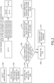
FIG. 2 , a flowchart of a method according to an exemplary embodiment is shown. A computer apparatus executing the method may select 200 an airport / runway andaccess 202 all terrain elevation tiles within some predetermined distance of that airport / runway. The computer apparatus may then sub-divide the terrain elevation tiles and determine new elevations for the newly created tiles with reference to stored terrain data. - In at least one embodiment, the computer apparatus may determine 206 if there is a mismatch between onboard flight sensor data and the elevation assigned to each newly created tile; flight sensor data may be compiled and correlated over a plurality of flights. If there is no mismatch, or any discrepancy is within some predetermined threshold, then computer apparatus processes 208 the new tiles to generate 210 a high-resolution portion of the database. If the computer apparatus determines 206 that a mismatch does exist, the computer apparatus may replace 212 elevations in the terrain database with the compiled and correlated sensor data for the corresponding tiles.
- In at least one embodiment, the computer apparatus may merge 214 symmetrical, adjacent tiles with the same elevation value to create one lower resolution tile where higher resolution data is unnecessary. It may be appreciated that tiles may be merged where the number and disposition of the tiles is conducive to create one single tile.
- Referring to
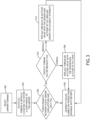
FIG. 3 , a flowchart of a method according to an exemplary embodiment is shown. A computer apparatus executing the method may select 300 an airport / runway andaccess 302 all terrain and obstacle elevation tiles within some predetermined distance of that airport / runway. The computer apparatus may determine 304 if there is a mismatch between onboard flight sensor data and the elevation assigned to each tile; flight sensor data may be compiled and correlated over a plurality of flights. If there is no mismatch, or any discrepancy is within some predetermined threshold, then computer apparatus produces 306 a production database. - If the computer apparatus determines 304 that a mismatch does exist, the computer apparatus may determine 310 if the mismatch is in the terrain database or the obstacle database. If the mismatch is in the terrain database, the computer apparatus replaces 308 the elevation value in the corresponding tile with the elevation value determined via the onboard flight sensor data. The elevation value determined via the onboard flight sensor data may be an average value determined over a plurality of flights, a weighted value according to the known accuracy of the corresponding sensor, a value from the known most accurate sensor constrained by other flight sensor data, or some other such methodology.
- If the mismatch is in the obstacle database, the computer apparatus replaces 312 the elevation value in the corresponding tile with the elevation value determined via the onboard flight sensor data and updates the accuracy attribute (including adding an accuracy attribute where none currently exists). The accuracy attribute may be defined by the range of flight sensor data values.
- When the mismatch has been corrected, the computer apparatus produces 306 the appropriate databases.
- In at least one embodiment, the computer apparatus may embody in a trained artificial intelligence such as a trained neural network.
- Referring to
FIG. 4 , a block diagram of aneural network 400 according an exemplary embodiment of the inventive concepts disclosed herein is shown. Theneural network 400 comprises aninput layer 402, andoutput layer 404, and a plurality ofinternal layers nodes input layer 402, eachnode 410 receives one ormore inputs output 412 based on an activation function unique to eachnode 410 in theinput layer 402. An activation function may be a Hyperbolic tangent function, a linear output function, and / or a logistic function, or some combination thereof, anddifferent nodes output 412 may comprise a real value with a defined range or a Boolean value if the activation function surpasses a defined threshold. Such ranges and thresholds may be defined during a training process. Furthermore, the synaptic weights are determined during the training process. -
Outputs 412 from each of thenodes 410 in theinput layer 402 are passed to eachnode 436 in a firstintermediate layer 406. The process continues through any number ofintermediate layers intermediate layer node input intermediate layer intermediate layer nodes layer nodes intermediate layer nodes inputs - An
output layer 404 including one ormore output nodes 440 receives theoutputs 416 from each of thenodes 438 in the previousintermediate layer 408. Eachoutput node 440 produces afinal output previous layer inputs 416. Such outputs may comprise separate components of an interleaved input signal, bits for delivery to a register, or other digital output based on an input signal and DSP algorithm. - In at least one embodiment, each
node layer node node subsequent layers node input more nodes initial input - In at least one embodiment, the number of
processing layers nodes -
Layers nodes previous layer subsequent layer - A trained neural network according to at least one exemplary embodiment may receive terrain data from one or more terrain and obstacle databases as input, and identify tiles to be broken up for greater granularity. Furthermore, the neural network may be trained to identify tiles to be combined based on elevation data within some threshold consistency.
- Embodiments of the present disclosure create adaptively greater resolution near an area of interest such as a runway. In another embodiment, the system may consolidate areas that do not need great resolution (e.g., flat, featureless areas) into larger tiles; reducing the overall size of the database.
- Furthermore, embodiments of the present disclosure refine elevation values in existing databases based on actually flight sensor data compiled over time. Flight sensor data may be used to establish accuracy metrics even when the elevation values remain unchanged.
- It is believed that the inventive concepts disclosed herein and many of their attendant advantages will be understood by the foregoing description of embodiments of the inventive concepts, and it will be apparent that various changes may be made in the form, construction, and arrangement of the components thereof without departing from the scope of the invention as defined by the claims. Furthermore, any of the features disclosed in relation to any of the individual embodiments may be incorporated into any other embodiment.
Claims (14)
- A method for improving accuracy of terrain and obstacle databases comprising:receiving terrain tile data from a terrain database (102) in a plurality of databases;receiving (200) a selected airport;identifying (202) at least one tile within a predefined radius of the selected airport;subdividing (204) the at least one tile into a plurality of tiles;determining an elevation for each of the plurality of tiles; andupdating (312) the terrain database with the plurality of tiles in place of the at least one tile.
- The method of Claim 1, wherein the elevation for each of the plurality of tiles is determined from database in the plurality of databases.
- The method of Claim 2, further comprising:receiving onboard sensor data from the plurality of databases, the onboard sensor data corresponding to a location of each of the plurality of tiles; andverifying the determined elevation for each of the plurality of tiles based on the onboard sensor data.
- The method of any preceding Claim, further comprising:identifying a plurality of similar elevation tiles from the terrain database;consolidating the similar elevation tiles into a single tile; andupdating the terrain database with the single tile.
- The method of any preceding Claim, further comprising:receiving onboard sensor data from the plurality of databases, the onboard sensor data corresponding terrain and obstacle elevations;identifying a terrain elevation or obstacle elevation from a corresponding terrain database or obstacle database in the plurality of databases; andverifying the terrain elevation or obstacle elevation based on the onboard sensor data.
- The method of Claim 5, further comprising:
determining an accuracy value of the terrain elevation or obstacle elevation; and updating the terrain database or obstacle database with the accuracy value. - The computer apparatus of Claim 6, wherein the accuracy value corresponds to a deviation among the onboard sensor data for the identified terrain elevation or obstacle elevation.
- A system comprising:a plurality of databases including a terrain database (102), an obstacle database (104), and an onboard flight sensor database (106); andat least one processor (100) in data communication with the plurality of databases and a memory storing processor executable code for configuring the at least one processor to:receive terrain elevation data from the terrain database;receive obstacle elevation data from the obstacle database;receive onboard sensor data from the onboard flight sensor database, theonboard sensor data corresponding terrain and obstacle elevations; and verify the terrain elevation data and obstacle elevation data based on theonboard sensor data.
- The system of Claim 8, wherein the at least one processor is further configured to:determine an accuracy value of the terrain elevation data and obstacle elevation data; andupdate the terrain database and obstacle database with the accuracy value.
- The system of Claim 8 or 9, wherein the at least one processor embodies a trained neural network.
- The system of Claim 8, 9 or 10, wherein the at least one processor is further configured to:receive a selected airport;identify at least one tile within a predefined radius of the selected airport;subdivide the at least one tile into a plurality of tiles;determine an elevation for each of the plurality of tiles; andupdate the terrain database with the plurality of tiles in place of the at least one tile.
- The system of any of Claims 8 to 11, wherein the elevation for each of the plurality of tiles is determined from database in the plurality of databases.
- The system of Claim 12, wherein the at least one processor is further configured to verify the determined elevation for each of the plurality of tiles based on the onboard sensor data.
- The system of any of Claims 8 to 13, wherein the at least one processor is further configured to:identify a plurality of similar elevation tiles from the terrain database;consolidate the similar elevation tiles into a single tile; andupdate the terrain database with the single tile.
Applications Claiming Priority (1)
| Application Number | Priority Date | Filing Date | Title |
|---|---|---|---|
| US18/523,095 US20250173361A1 (en) | 2023-11-29 | 2023-11-29 | Terrain database adaptive resolution method |
Publications (1)
| Publication Number | Publication Date |
|---|---|
| EP4563945A1 true EP4563945A1 (en) | 2025-06-04 |
Family
ID=93741553
Family Applications (1)
| Application Number | Title | Priority Date | Filing Date |
|---|---|---|---|
| EP24216290.7A Pending EP4563945A1 (en) | 2023-11-29 | 2024-11-28 | Terrain database adaptive resolution method |
Country Status (2)
| Country | Link |
|---|---|
| US (1) | US20250173361A1 (en) |
| EP (1) | EP4563945A1 (en) |
Citations (2)
| Publication number | Priority date | Publication date | Assignee | Title |
|---|---|---|---|---|
| DE10308913A1 (en) * | 2003-02-28 | 2004-09-30 | Ais Advanced Infodata Systems Gmbh | Aircraft safety system uses a data representation of the earth's surface in which a high resolution data mesh provides position and height data |
| WO2022152723A1 (en) * | 2021-01-12 | 2022-07-21 | Thales | Electronic device for storing a terrain database, method for generating such a database, avionics system, monitoring method and associated computer programs |
Family Cites Families (14)
| Publication number | Priority date | Publication date | Assignee | Title |
|---|---|---|---|---|
| US8207966B2 (en) * | 2004-05-26 | 2012-06-26 | Sony Online Entertainment Llc | Terrain editor tool for rule-based procedural terrain generation |
| CN102027468B (en) * | 2008-05-16 | 2014-04-23 | 上海惠普有限公司 | Provide geographic imagery for retrieval |
| WO2011153624A2 (en) * | 2010-06-11 | 2011-12-15 | Ambercore Software Inc. | System and method for manipulating data having spatial coordinates |
| WO2015010165A1 (en) * | 2013-07-23 | 2015-01-29 | National Ict Australia Limited | Geo-located activity visualisation, editing and sharing |
| WO2020081336A1 (en) * | 2018-10-14 | 2020-04-23 | Bentley Systems, Incorporated | Dynamic frontend-driven generation of an hlod tree |
| CA3023564C (en) * | 2018-11-07 | 2023-10-17 | Eidos Interactive Corp. | Computer graphics method for terrain rendering |
| US11321563B2 (en) * | 2019-08-28 | 2022-05-03 | Honeywell Aerospace Sas | Handling of ARAIM terrain database induced errors |
| US20210392314A1 (en) * | 2020-01-09 | 2021-12-16 | JUC Holdings Limited | Vehicle terrain capture system and display of 3d digital image and 3d sequence |
| US11721226B2 (en) * | 2020-01-13 | 2023-08-08 | Gulfstream Aerospace Corporation | Terrain database carving around runways |
| US11232630B2 (en) * | 2020-04-15 | 2022-01-25 | Cesium GS, Inc. | Systems and methods for terrain modification at runtime using displacement mapping |
| US11741625B2 (en) * | 2020-06-12 | 2023-08-29 | Elphel, Inc. | Systems and methods for thermal imaging |
| US12031836B2 (en) * | 2021-06-07 | 2024-07-09 | Apple Inc. | Map data adjustments for anomaly correction |
| CN114577233B (en) * | 2022-05-05 | 2022-07-29 | 腾讯科技(深圳)有限公司 | Vehicle navigation method and device, computer equipment and storage medium |
| EP4586209A1 (en) * | 2023-09-11 | 2025-07-16 | Ubotica Technologies Ltd. | System and method for performing geolocating and georeferencing of sensing data at remote sources |
-
2023
- 2023-11-29 US US18/523,095 patent/US20250173361A1/en active Pending
-
2024
- 2024-11-28 EP EP24216290.7A patent/EP4563945A1/en active Pending
Patent Citations (3)
| Publication number | Priority date | Publication date | Assignee | Title |
|---|---|---|---|---|
| DE10308913A1 (en) * | 2003-02-28 | 2004-09-30 | Ais Advanced Infodata Systems Gmbh | Aircraft safety system uses a data representation of the earth's surface in which a high resolution data mesh provides position and height data |
| WO2022152723A1 (en) * | 2021-01-12 | 2022-07-21 | Thales | Electronic device for storing a terrain database, method for generating such a database, avionics system, monitoring method and associated computer programs |
| US20240083592A1 (en) * | 2021-01-12 | 2024-03-14 | Thales | Electronic device for storing a terrain database, method for generating such a database, related avionics system, monitoring method and computer programs |
Also Published As
| Publication number | Publication date |
|---|---|
| US20250173361A1 (en) | 2025-05-29 |
Similar Documents
| Publication | Publication Date | Title |
|---|---|---|
| Olive et al. | Detection and identification of significant events in historical aircraft trajectory data | |
| US9613269B2 (en) | Identifying and tracking convective weather cells | |
| CN113780395A (en) | Mass high-dimensional AIS trajectory data clustering method | |
| Weinert et al. | Uncorrelated encounter model of the national airspace system, version 2.0 | |
| US10520597B2 (en) | Aircraft radar system for bird and bat strike avoidance | |
| US20060224318A1 (en) | Trajectory prediction | |
| JP2019532380A (en) | Change detection based image acquisition tasking system | |
| CN114175099A (en) | Quad-tree terrain data compression using distance-based pruning | |
| AU2020225810B2 (en) | Bespoke detection model | |
| CN120313611B (en) | An intelligent obstacle avoidance system for drones based on lidar | |
| Kochenderfer et al. | Uncorrelated Encounter Model of the National Airspace System, Version 1.0 | |
| CN114565176A (en) | Long-term ship track prediction method | |
| CN120448850A (en) | A spatiotemporal intelligent ocean satellite IoT perception information screening method and device | |
| Eckstein et al. | Threaded track: Geospatial data fusion for aircraft flight trajectories | |
| US20250173361A1 (en) | Terrain database adaptive resolution method | |
| US11113292B2 (en) | Feature data storage apparatus and driving feature and distribution databases | |
| Gebre-Egziabher et al. | Design and performance analysis of a low-cost aided-dead reckoning navigation system | |
| CN118747347A (en) | Multi-source and multi-layer fusion method of slope runway height based on improved Kalman filter | |
| Klaproth et al. | Off-design mission performance prediction for unmanned aerial vehicles based on machine learning | |
| CN120847828B (en) | Star selection method for autonomous integrity monitoring of advanced receiver | |
| CN119511237B (en) | Multi-platform-based laser radar measurement method and device | |
| CN120354257B (en) | A method and system for aircraft attribute identification based on multi-source data fusion | |
| CN121384047B (en) | A Navigation Method and System for Unmanned Aerial Vehicles Based on Spatial 3D Mesh Coding | |
| CN121028067B (en) | Unmanned aerial vehicle bee colony detection method and system based on multilayer early warning | |
| CN118797288B (en) | Ultra-large-scale remote sensing star group optimal task star prediction method based on BP neural network |
Legal Events
| Date | Code | Title | Description |
|---|---|---|---|
| PUAI | Public reference made under article 153(3) epc to a published international application that has entered the european phase |
Free format text: ORIGINAL CODE: 0009012 |
|
| STAA | Information on the status of an ep patent application or granted ep patent |
Free format text: STATUS: THE APPLICATION HAS BEEN PUBLISHED |
|
| AK | Designated contracting states |
Kind code of ref document: A1 Designated state(s): AL AT BE BG CH CY CZ DE DK EE ES FI FR GB GR HR HU IE IS IT LI LT LU LV MC ME MK MT NL NO PL PT RO RS SE SI SK SM TR |
|
| STAA | Information on the status of an ep patent application or granted ep patent |
Free format text: STATUS: REQUEST FOR EXAMINATION WAS MADE |
|
| 17P | Request for examination filed |
Effective date: 20251204 |
|
| STAA | Information on the status of an ep patent application or granted ep patent |
Free format text: STATUS: EXAMINATION IS IN PROGRESS |