EP4563942A1 - Vehicle trajectory recording system and method for vehicles with a sensor - Google Patents
Vehicle trajectory recording system and method for vehicles with a sensor Download PDFInfo
- Publication number
- EP4563942A1 EP4563942A1 EP24205316.3A EP24205316A EP4563942A1 EP 4563942 A1 EP4563942 A1 EP 4563942A1 EP 24205316 A EP24205316 A EP 24205316A EP 4563942 A1 EP4563942 A1 EP 4563942A1
- Authority
- EP
- European Patent Office
- Prior art keywords
- vehicle
- driving event
- event
- recording
- sensing information
- Prior art date
- Legal status (The legal status is an assumption and is not a legal conclusion. Google has not performed a legal analysis and makes no representation as to the accuracy of the status listed.)
- Pending
Links
Images





Classifications
-
- G—PHYSICS
- G01—MEASURING; TESTING
- G01C—MEASURING DISTANCES, LEVELS OR BEARINGS; SURVEYING; NAVIGATION; GYROSCOPIC INSTRUMENTS; PHOTOGRAMMETRY OR VIDEOGRAMMETRY
- G01C21/00—Navigation; Navigational instruments not provided for in groups G01C1/00 - G01C19/00
- G01C21/26—Navigation; Navigational instruments not provided for in groups G01C1/00 - G01C19/00 specially adapted for navigation in a road network
-
- G—PHYSICS
- G01—MEASURING; TESTING
- G01S—RADIO DIRECTION-FINDING; RADIO NAVIGATION; DETERMINING DISTANCE OR VELOCITY BY USE OF RADIO WAVES; LOCATING OR PRESENCE-DETECTING BY USE OF THE REFLECTION OR RERADIATION OF RADIO WAVES; ANALOGOUS ARRANGEMENTS USING OTHER WAVES
- G01S19/00—Satellite radio beacon positioning systems; Determining position, velocity or attitude using signals transmitted by such systems
- G01S19/38—Determining a navigation solution using signals transmitted by a satellite radio beacon positioning system
- G01S19/39—Determining a navigation solution using signals transmitted by a satellite radio beacon positioning system the satellite radio beacon positioning system transmitting time-stamped messages, e.g. GPS [Global Positioning System], GLONASS [Global Orbiting Navigation Satellite System] or GALILEO
- G01S19/42—Determining position
- G01S19/45—Determining position by combining measurements of signals from the satellite radio beacon positioning system with a supplementary measurement
- G01S19/47—Determining position by combining measurements of signals from the satellite radio beacon positioning system with a supplementary measurement the supplementary measurement being an inertial measurement, e.g. tightly coupled inertial
-
- G—PHYSICS
- G07—CHECKING-DEVICES
- G07C—TIME OR ATTENDANCE REGISTERS; REGISTERING OR INDICATING THE WORKING OF MACHINES; GENERATING RANDOM NUMBERS; VOTING OR LOTTERY APPARATUS; ARRANGEMENTS, SYSTEMS OR APPARATUS FOR CHECKING NOT PROVIDED FOR ELSEWHERE
- G07C5/00—Registering or indicating the working of vehicles
- G07C5/08—Registering or indicating performance data other than driving, working, idle, or waiting time, with or without registering driving, working, idle or waiting time
- G07C5/0841—Registering performance data
- G07C5/085—Registering performance data using electronic data carriers
Definitions
- GNSS Global Navigation Satellite System
- GPS Global Positioning System
- GPS is a satellite system owned by the U.S. government, and users can use other systems such as GLONASS, Galileo, and BeiDou to obtain GNSS positions. While a vehicle is driven, it can obtain the driving trajectory by recording the GNSS position and apply it to map tools or servers.
- FIG. 1 For example, to illustrate the time interval sampling error, please refer to Figure 1 for the actual trajectory of the vehicle.
- the vehicle's trajectory passes through points A, B, C, and D, before returning to point A, sequentially following path P11, path P12, path P13, and path P14.
- the vehicle records its trajectory using a time interval sampling method.
- the recorded trajectory passes through point A, point B, point C1, point C2, and point D, before returning to point A, sequentially following path P21, path P22, path P23, path P24, and path P25.
- the recorded trajectory of the vehicle passes through point A, point B, point C3, point C4, point D, point E, point F and then returns to point A, sequentially following path P31, path P32, and path P33 path P34, path P35, path P36 and path P37.
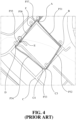
- the time interval sampling method is used alone with a basic point-to-point connection, the recorded results may either capture non-existent turning events or miss actual turning events. This can lead to incomplete and inaccurate driving trajectories, as shown in Figures 3 and 4 .
- the present invention relates to a vehicle trajectory technology, in particular to a vehicle trajectory recording system and method for vehicles with a sensor.
- a primary objective of the present invention is to provide a vehicle trajectory recording system and method for vehicles with a sensor. Changes in the vehicle's direction of travel can be detected by angle detectors, such as gyroscopes, accelerators and torque sensors, and then, algorithms can be used to determine whether the vehicle has performed driving events such as turning. When the above-mentioned driving event (such as a turn) is detected, the vehicle's position is recorded and sent back to the system, and further, the vehicle's position is recorded with the GNSS map and its driving trajectory is adjusted to obtain accurate, clear and complete driving trajectory. Namely, by combining the detection of vehicle turning events and the recording of vehicle positions in the GNSS system, the present invention can effectively solve the above-mentioned error problems caused by using the interval sampling method alone and the problem of excessive data generated by continuous recording.
- a vehicle trajectory recording system comprises a sensor disposed on a vehicle, a control module electrically connected to the sensor and configured to receive a sensing information from the sensor, analyze the sensing information to determine a traveling direction change event for the vehicle and analyze the traveling direction change event for determining a driving event of the vehicle, and a recording module electrically connected to the control module and configured to record a position of the vehicle where the vehicle performed the driving event , marking the position on a map where the vehicle performed the driving event, and adjusting a driving trajectory of the vehicle.
- a vehicle trajectory recording method comprises receiving a sensing information from a sensor on a vehicle, analyzing the sensing information to detect a traveling direction change event of the vehicle, determining whether the vehicle performs a driving event according to the traveling direction change event, recording a position where the vehicle performed the driving event, when the vehicle is detected to be performing the driving event, marking the position where the vehicle performs the driving event on a map, and adjusting a driving trajectory of the vehicle.
- the senor is an angle detector, and the angle detector includes a gyroscope, an accelerator or a torque sensor.
- the senor includes a plurality of angle detectors.
- the driving event is a turn.
- the step of analyzing the sensing information includes continuously calculating an average value of an angle data obtained within a fixed period of time, and determining whether the average value of the angle data is greater than a threshold value; if the average value of the angle data is greater than a threshold value, the driving event, which is the turn, is sensed; if the average value of the angle data is not greater than a threshold value, the driving event does not occur.
- the angle detector is an accelerator
- the steps of analyzing the sensing information further comprise performing a calculation on the sensing information obtained from the accelerator to obtain the angle data, wherein the calculation is performed by determining an angle between the two force vectors of instantaneous accelerations at two time points.
- the position is positioned via a Global Navigation Satellite System (GNSS), and the map is a GNSS map.
- GNSS Global Navigation Satellite System
- positioning and recording position are performed according to a time interval sampling method, and monitoring whether the driving event of the vehicle of the turn occurs, if the driving event of the turn occurs, a current position of the driving event of the vehicle turning is recorded; and recalculating the time interval of the time interval sampling method.
- the method is used in vehicle terminal boxes and smartphones.
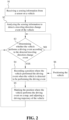
- FIG. 2 is a flow chart of a vehicle trajectory recording method of the present invention.
- the present invention provides a vehicle trajectory recording method that can be used in vehicle terminal boxes (Telematics BOX) and smartphones.
- the vehicle trajectory recording method of the present invention includes: receiving a sensing information from at least one sensor on a vehicle (step S1); analyzing the sensing information to detect a traveling direction change event of the vehicle (step S2); determining whether the vehicle performs a driving event according to the detected traveling direction change event (step S3); recording a position where the vehicle performed the driving event when the vehicle is detected performing the driving event (step S4); and marking the position where the vehicle performs the driving event on a map, and adjusting a driving trajectory of the vehicle (step S5).
- step S2 the position can be recorded by using the conventional time interval sampling method. And, in step S3, it is monitored whether a driving event of the vehicle turning occurs. If the driving event of the vehicle turning occurs, the current position where the driving event of the vehicle turning occurs is recorded in step S4; furthermore, the time for "time interval sampling" will be reset to zero and recalculated. For example, the original time interval sampling records the vehicle position every 5 seconds. Therefore, assuming a recording is made at 0 seconds, the next recording should ideally occur at the 5th second.
- the timer will also be reset from 3 seconds to 0 seconds, and the 5-second interval calculation will be restarted. Namely, if there is no further driving event of the vehicle turning after the aforementioned 3 seconds, the next position recording will be made at the 8th second.
- step S6 positioning the vehicle is performed (step S6).
- positioning the vehicle can be performed via a Global Navigation Satellite System (GNSS).
- GNSS Global Navigation Satellite System
- each position in the vehicle trajectory recording method of the present invention is positioned through a global satellite navigation system (GNSS), but it is not limited thereto.
- GNSS global satellite navigation system
- the map used in the present invention may be a GNSS map.
- traveling direction change and driving events in the vehicle trajectory recording method of the present invention can be detected through an angle detector.
- the angle detector may include a gyroscope, an accelerometer or a torque sensor, but is not limited thereto.
- the turning angle, angular speed or torque of the vehicle sensed by the angle detector can be defined and adjusted according to the precision of the angle detector or the accuracy desired by the designer.
- step S1 the turning angle of the vehicle will be continuously collected from the angle detector (the angle detector includes a gyroscope, accelerator or torque sensor).
- step S2 the average value of the angle data collected within a fixed period of time is continuously calculated, and in step S3, if it is detected that the average value exceeds a threshold value, it is deemed that a turning driving event has occurred.
- the threshold value of the angle is 8-15 degrees, but is not limited thereto.
- Figure 5 is a schematic diagram of the vehicle trajectory recording method of the present invention, taking a threshold of 8 degrees per second for the angle data as an example.
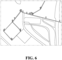
- Figure 6 is a schematic diagram of the vehicle trajectory recording method of the present invention, taking a threshold of 15 degrees per second for the angle data as an example. Please refer to Figure 5 and Figure 6 at the same time, which show the path record icons after using 8 degrees and 15 degrees as the threshold values of the angle data respectively. It can be found that, compared to the results shown in Figures 3 and 4 from the aforementioned time interval control sampling method, the position recordings in Figures 5 and 6 are relatively more accurate.
- FIG 7 is a flowchart of the angle detector collecting and calculating angle data in the vehicle trajectory recording method of the present invention.
- the step of detecting the vehicle's traveling direction by analyzing the sensing information from step S1 further includes obtaining an angle data (step S61); continuously calculating the average value of the angle data obtained within a fixed period of time (step S62); determining whether the average value of the angle data is greater than a threshold value (step S63); if the average value of the angle data is greater than a threshold value, a driving event of vehicle turning is sensed (step S64); if the average value of the angle data is not greater than a threshold value, no driving event occurs (step S65).
- the angle detector is an accelerator
- the step of analyzing the sensing information further comprises, in step S61, calculating the sensing information obtained from the accelerator to obtain the angle data.
- the calculation is performed by finding the angle between two force vectors of the instantaneous accelerations at two time points before and after (please refer to the following paragraphs for explanation).
- the system of the present invention can integrate angle detectors such as gyroscopes, accelerometers or torque sensors to detect changes in the vehicle's traveling direction. Therefore, in the processing of acquired angle data, different processing methods are applied depending on the data source. If the data sources are gyroscopes and torque sensors, the angle data can be acquired without additional data calculations. However, if the data source is an accelerator, additional calculations are required to obtain the angle data. This calculation can be performed by finding the angle between two vectors. For example, the angle can be found between vector A (the acceleration force vector at time point T 0 ) and vector B (the acceleration force vector at time point T 1 ).
- Figure 8 is a structural block diagram of a vehicle trajectory recording system for recording a trajectory of a vehicle with a sensor according to the present invention.
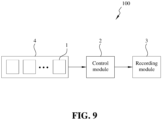
- Figure 9 is a structural block diagram of a vehicle trajectory recording system for recording a trajectory of a vehicle with a plurality of sensors according to the present invention.
- the vehicle trajectory system 100 for recording the trajectories of vehicles with sensors of the present invention includes a sensor 1, a control module 2 and a recording module 3, wherein, the sensor 1 can comprise one sensor (as shown in Figure 8 ) or a plurality of sensors (as shown in Figure 9 ), and the following embodiments take the plurality of sensors (as shown in Figure 9 ) as an example for explanation.
- a plurality of the sensors 1 may be disposed on a vehicle 4.
- the control module 2 is electrically connected to the plurality of sensors 1 and configured to: receiving a sensing information from the plurality of sensors 1; analyzing the sensing information to determine a traveling direction change event for the vehicle 4; and analyzing the traveling direction change event and determining a driving event for the vehicle 4. That is, the control module 2 is configured to perform step S1 and step S3.
- the recording module 3 is electrically connected to the control module 2 and configured to: recording a position of the vehicle 4 at which the driving event occurred; marking the position on a map where the vehicle 4 performed the driving event; and adjusting a driving trajectory of the vehicle 4. Namely, the recording module 3 is configured to perform steps S4 to S5.
- angle detectors such as gyroscopes, accelerators or torque sensors are used to detect changes in the vehicle's traveling direction, and then an algorithm is used to determine whether the vehicle has performed a driving event such as a turn; when the above-mentioned driving event (such as the turn) is detected, the vehicle's position can be recorded and sent back to the system. It is used with the GNSS map to record the vehicle's position and adjust vehicle's driving trajectory to obtain accurate and complete driving trajectory.
Landscapes
- Engineering & Computer Science (AREA)
- Radar, Positioning & Navigation (AREA)
- Remote Sensing (AREA)
- Physics & Mathematics (AREA)
- General Physics & Mathematics (AREA)
- Computer Networks & Wireless Communication (AREA)
- Automation & Control Theory (AREA)
- Navigation (AREA)
- Traffic Control Systems (AREA)
Abstract
A vehicle trajectory recording system and method for vehicles with a sensor is disclosed. The system includes a sensor arranged on a vehicle; a control module, electrically connected to the sensor and configured to receive a piece of sensing information from the sensor, analyze the sensing information to determine a traveling direction change event of the vehicle, and analyze the traveling direction change event and determine a driving event of the vehicle; and a recording module, electrically connected to the control module and configured to record a position of the vehicle where the vehicle performed the driving event, mark the position of the vehicle on a map where the driving event occurred, and adjust a driving trajectory of the vehicle.
Description
- This application claims the priority of
Taiwanese patent application No. 112146684, filed on November 30, 2023 - Global Navigation Satellite System (GNSS) provides geographical positioning to signal receivers anywhere on or near the earth through unobstructed connection of four or more GPS (Global Positioning System) satellites and time information.
- GPS is a satellite system owned by the U.S. government, and users can use other systems such as GLONASS, Galileo, and BeiDou to obtain GNSS positions. While a vehicle is driven, it can obtain the driving trajectory by recording the GNSS position and apply it to map tools or servers.
- Traditional methods of using GNSS systems for trajectory recording include time interval sampling, distance interval sampling and continuous sampling. However, in both time interval sampling method and distance interval sampling method, errors will occur due to the sampling interval. In the driving trajectory of actual driving cases, part of the trajectory may be missed, resulting in recording results that are inconsistent with the actual moving path. In addition, continuous sampling may easily collect excessive data, resulting in significant consumption of device capacity and computing resources.
- For example, to illustrate the time interval sampling error, please refer to
Figure 1 for the actual trajectory of the vehicle. The vehicle's trajectory passes through points A, B, C, and D, before returning to point A, sequentially following path P11, path P12, path P13, and path P14. - Please refer to
Figure 3 , the vehicle records its trajectory using a time interval sampling method. The recorded trajectory passes through point A, point B, point C1, point C2, and point D, before returning to point A, sequentially following path P21, path P22, path P23, path P24, and path P25. Please refer toFigure 4 again, the recorded trajectory of the vehicle passes through point A, point B, point C3, point C4, point D, point E, point F and then returns to point A, sequentially following path P31, path P32, and path P33 path P34, path P35, path P36 and path P37. Namely, when the time interval sampling method is used alone with a basic point-to-point connection, the recorded results may either capture non-existent turning events or miss actual turning events. This can lead to incomplete and inaccurate driving trajectories, as shown inFigures 3 and4 . - The present invention relates to a vehicle trajectory technology, in particular to a vehicle trajectory recording system and method for vehicles with a sensor.
- A primary objective of the present invention is to provide a vehicle trajectory recording system and method for vehicles with a sensor. Changes in the vehicle's direction of travel can be detected by angle detectors, such as gyroscopes, accelerators and torque sensors, and then, algorithms can be used to determine whether the vehicle has performed driving events such as turning. When the above-mentioned driving event (such as a turn) is detected, the vehicle's position is recorded and sent back to the system, and further, the vehicle's position is recorded with the GNSS map and its driving trajectory is adjusted to obtain accurate, clear and complete driving trajectory. Namely, by combining the detection of vehicle turning events and the recording of vehicle positions in the GNSS system, the present invention can effectively solve the above-mentioned error problems caused by using the interval sampling method alone and the problem of excessive data generated by continuous recording.
- A vehicle trajectory recording system comprises a sensor disposed on a vehicle, a control module electrically connected to the sensor and configured to receive a sensing information from the sensor, analyze the sensing information to determine a traveling direction change event for the vehicle and analyze the traveling direction change event for determining a driving event of the vehicle, and a recording module electrically connected to the control module and configured to record a position of the vehicle where the vehicle performed the driving event , marking the position on a map where the vehicle performed the driving event, and adjusting a driving trajectory of the vehicle.
- A vehicle trajectory recording method comprises receiving a sensing information from a sensor on a vehicle, analyzing the sensing information to detect a traveling direction change event of the vehicle, determining whether the vehicle performs a driving event according to the traveling direction change event, recording a position where the vehicle performed the driving event, when the vehicle is detected to be performing the driving event, marking the position where the vehicle performs the driving event on a map, and adjusting a driving trajectory of the vehicle.
- In some embodiments, the sensor is an angle detector, and the angle detector includes a gyroscope, an accelerator or a torque sensor.
- In some embodiments, the sensor includes a plurality of angle detectors.
- In some embodiments, the driving event is a turn.
- In some embodiments, the step of analyzing the sensing information includes continuously calculating an average value of an angle data obtained within a fixed period of time, and determining whether the average value of the angle data is greater than a threshold value; if the average value of the angle data is greater than a threshold value, the driving event, which is the turn, is sensed; if the average value of the angle data is not greater than a threshold value, the driving event does not occur.
- In some embodiments, the angle detector is an accelerator, and the steps of analyzing the sensing information further comprise performing a calculation on the sensing information obtained from the accelerator to obtain the angle data, wherein the calculation is performed by determining an angle between the two force vectors of instantaneous accelerations at two time points.
- In some embodiments, the position is positioned via a Global Navigation Satellite System (GNSS), and the map is a GNSS map.
- In some embodiments, while the step of determining a traveling direction change event for the vehicle is executed, positioning and recording position are performed according to a time interval sampling method, and monitoring whether the driving event of the vehicle of the turn occurs, if the driving event of the turn occurs, a current position of the driving event of the vehicle turning is recorded; and recalculating the time interval of the time interval sampling method.
- In some embodiments, the method is used in vehicle terminal boxes and smartphones.
- Aspects of the present invention are best understood from the following detailed description when read with the accompanying figures. It is noted that, in accordance with the standard practice in the industry, various features are not drawn to scale. In fact, the dimensions of the various features may be increased or reduced for clarity of discussion.
-
Figure 1 is a schematic diagram of an actual vehicle movement path. -
Figure 2 is a flow chart of a vehicle trajectory recording method of the present invention. -
Figure 3 is a schematic diagram of the first vehicle movement trajectory with errors by using conventional time interval control sampling. -
Figure 4 is a schematic diagram of the second vehicle movement trajectory with errors by using conventional time interval control sampling. -
Figure 5 is a schematic diagram of the vehicle trajectory recording method of the present invention, taking a threshold of 8 degrees per second for the angle data as an example. -
Figure 6 is a schematic diagram of the vehicle trajectory recording method of the present invention, taking a threshold of 15 degrees per second for the angle data as an example. -
Figure 7 is a flowchart of the process of collecting and calculating angle data by the angle detector in the vehicle trajectory recording method of the present invention. -
Figure 8 is a structural block diagram of a vehicle trajectory recording system for recording a trajectory of a vehicle with a sensor according to the present invention. -
Figure 9 is a structural block diagram of a vehicle trajectory recording system for recording a trajectory of a vehicle with a plurality of sensors according to the present invention. - It will be appreciated that, although specific embodiments of the present invention are described herein for purposes of illustration, various modifications may be made without departing from the spirit and scope of the present invention.
- In the following description, certain specific details are set forth in order to provide a thorough understanding of various aspects of the disclosed subject matter. However, the disclosed subject matter may be practiced without these specific details. In some instances, well-known structures and methods of power delivery comprising embodiments of the subject matter disclosed herein have not been described in detail to avoid obscuring the descriptions of other aspects of the present invention.
- Unless the context requires otherwise, throughout the specification and claims that follow, the word "comprise," "have," "include," and variations thereof, such as "comprises," "comprising," "having," "including" are to be construed in an open, inclusive sense, that is, as "including, but not limited to."
- Reference throughout the specification to "one embodiment" or "an embodiment" means that a particular feature, structure, or characteristic described in connection with the embodiment is included in at least one embodiment. Thus, the appearance of the phrases "in one embodiment" or "in an embodiment" in various places throughout the specification are not necessarily all referring to the same aspect. Furthermore, the particular features, structures, or characteristics may be combined in any suitable manner in one or more aspects of the present invention.
-
Figure 2 is a flow chart of a vehicle trajectory recording method of the present invention. Please refer toFigure 2 , the present invention provides a vehicle trajectory recording method that can be used in vehicle terminal boxes (Telematics BOX) and smartphones. The vehicle trajectory recording method of the present invention includes: receiving a sensing information from at least one sensor on a vehicle (step S1); analyzing the sensing information to detect a traveling direction change event of the vehicle (step S2); determining whether the vehicle performs a driving event according to the detected traveling direction change event (step S3); recording a position where the vehicle performed the driving event when the vehicle is detected performing the driving event (step S4); and marking the position where the vehicle performs the driving event on a map, and adjusting a driving trajectory of the vehicle (step S5). - In step S2, the position can be recorded by using the conventional time interval sampling method. And, in step S3, it is monitored whether a driving event of the vehicle turning occurs. If the driving event of the vehicle turning occurs, the current position where the driving event of the vehicle turning occurs is recorded in step S4; furthermore, the time for "time interval sampling" will be reset to zero and recalculated. For example, the original time interval sampling records the vehicle position every 5 seconds. Therefore, assuming a recording is made at 0 seconds, the next recording should ideally occur at the 5th second. However, since a driving event of the vehicle turning occurred at the 3rd second, at this time, in addition to initiating the position recording due to the driving event of the vehicle turning, the timer will also be reset from 3 seconds to 0 seconds, and the 5-second interval calculation will be restarted. Namely, if there is no further driving event of the vehicle turning after the aforementioned 3 seconds, the next position recording will be made at the 8th second.
- In some embodiments, while the vehicle is detected to be performing the driving event in step S4, positioning the vehicle is performed (step S6). Preferably, positioning the vehicle can be performed via a Global Navigation Satellite System (GNSS).
- In some embodiments, each position in the vehicle trajectory recording method of the present invention is positioned through a global satellite navigation system (GNSS), but it is not limited thereto. In this embodiment, the map used in the present invention may be a GNSS map.
- In some embodiments, traveling direction change and driving events (such as turning) in the vehicle trajectory recording method of the present invention can be detected through an angle detector. Preferably, the angle detector may include a gyroscope, an accelerometer or a torque sensor, but is not limited thereto. Taking the vehicle turning as an example of a driving event, the turning angle, angular speed or torque of the vehicle sensed by the angle detector can be defined and adjusted according to the precision of the angle detector or the accuracy desired by the designer. In step S1, the turning angle of the vehicle will be continuously collected from the angle detector (the angle detector includes a gyroscope, accelerator or torque sensor). In step S2, the average value of the angle data collected within a fixed period of time is continuously calculated, and in step S3, if it is detected that the average value exceeds a threshold value, it is deemed that a turning driving event has occurred. In some embodiments, the threshold value of the angle is 8-15 degrees, but is not limited thereto.
-
Figure 5 is a schematic diagram of the vehicle trajectory recording method of the present invention, taking a threshold of 8 degrees per second for the angle data as an example.Figure 6 is a schematic diagram of the vehicle trajectory recording method of the present invention, taking a threshold of 15 degrees per second for the angle data as an example. Please refer toFigure 5 andFigure 6 at the same time, which show the path record icons after using 8 degrees and 15 degrees as the threshold values of the angle data respectively. It can be found that, compared to the results shown inFigures 3 and4 from the aforementioned time interval control sampling method, the position recordings inFigures 5 and6 are relatively more accurate. -
Figure 7 is a flowchart of the angle detector collecting and calculating angle data in the vehicle trajectory recording method of the present invention. Please refer toFigures 2 and7 , in step S2 ofFigure 2 , the step of detecting the vehicle's traveling direction by analyzing the sensing information from step S1 further includes obtaining an angle data (step S61); continuously calculating the average value of the angle data obtained within a fixed period of time (step S62); determining whether the average value of the angle data is greater than a threshold value (step S63); if the average value of the angle data is greater than a threshold value, a driving event of vehicle turning is sensed (step S64); if the average value of the angle data is not greater than a threshold value, no driving event occurs (step S65). In some embodiments, the angle detector is an accelerator, the step of analyzing the sensing information further comprises, in step S61, calculating the sensing information obtained from the accelerator to obtain the angle data. The calculation is performed by finding the angle between two force vectors of the instantaneous accelerations at two time points before and after (please refer to the following paragraphs for explanation). - The system of the present invention can integrate angle detectors such as gyroscopes, accelerometers or torque sensors to detect changes in the vehicle's traveling direction. Therefore, in the processing of acquired angle data, different processing methods are applied depending on the data source. If the data sources are gyroscopes and torque sensors, the angle data can be acquired without additional data calculations. However, if the data source is an accelerator, additional calculations are required to obtain the angle data. This calculation can be performed by finding the angle between two vectors. For example, the angle can be found between vector A (the acceleration force vector at time point T0) and vector B (the acceleration force vector at time point T1).
-
Figure 8 is a structural block diagram of a vehicle trajectory recording system for recording a trajectory of a vehicle with a sensor according to the present invention.Figure 9 is a structural block diagram of a vehicle trajectory recording system for recording a trajectory of a vehicle with a plurality of sensors according to the present invention. Please refer toFigure 8 andfigure 9 , thevehicle trajectory system 100 for recording the trajectories of vehicles with sensors of the present invention includes asensor 1, acontrol module 2 and arecording module 3, wherein, thesensor 1 can comprise one sensor (as shown inFigure 8 ) or a plurality of sensors (as shown inFigure 9 ), and the following embodiments take the plurality of sensors (as shown inFigure 9 ) as an example for explanation. - A plurality of the
sensors 1 may be disposed on avehicle 4. - The
control module 2 is electrically connected to the plurality ofsensors 1 and configured to: receiving a sensing information from the plurality ofsensors 1; analyzing the sensing information to determine a traveling direction change event for thevehicle 4; and analyzing the traveling direction change event and determining a driving event for thevehicle 4. That is, thecontrol module 2 is configured to perform step S1 and step S3. - The
recording module 3 is electrically connected to thecontrol module 2 and configured to: recording a position of thevehicle 4 at which the driving event occurred; marking the position on a map where thevehicle 4 performed the driving event; and adjusting a driving trajectory of thevehicle 4. Namely, therecording module 3 is configured to perform steps S4 to S5. - Through the above method, angle detectors such as gyroscopes, accelerators or torque sensors are used to detect changes in the vehicle's traveling direction, and then an algorithm is used to determine whether the vehicle has performed a driving event such as a turn; when the above-mentioned driving event (such as the turn) is detected, the vehicle's position can be recorded and sent back to the system. It is used with the GNSS map to record the vehicle's position and adjust vehicle's driving trajectory to obtain accurate and complete driving trajectory.
Claims (15)
- A vehicle trajectory recording system for recording a trajectory of a vehicle, comprising:a sensor, disposed on the vehicle;a control module, electrically connected to the sensor and configured to receive a sensing information from the sensor, analyze the sensing information to determine a traveling direction change event for the vehicle, and analyze the traveling direction change event for determining a driving event of the vehicle; anda recording module, electrically connected to the control module and configured to record a position of the vehicle where the vehicle performs the driving event, and mark the position on a map where the vehicle performed the driving event.
- The system according to claim 1, wherein the sensor comprises an angle detector, and the angle detector comprises a gyroscope, an accelerator or a torque sensor.
- The system according to claim 2, wherein the driving event is a turn.
- The system according to claim 3, wherein the step of analyzing the sensing information comprises continuously calculating an average value of an angle data obtained within a fixed period of time; determining whether the average value of the angle data is greater than a threshold value; and if the average value of the angle data is greater than a threshold value, the driving event of the turn is sensed, and if the average value of the angle data is not greater than a threshold value, the driving event does not occur.
- The system according to claim 4, wherein the angle detector is an accelerator, and the step of analyzing the sensing information further comprises performing a calculation on the sensing information obtained from the accelerator to obtain the angle data, wherein the calculation is performed by determining an angle between the two force vectors of instantaneous accelerations at two time points.
- The system according to claim 3, wherein while the step of determining a traveling direction change event for the vehicle is executed, positioning and position recording are performed according to a time interval sampling method, and monitoring whether the driving event of the vehicle of the turn occurs, if there is the driving event of the turn occurs, then recording a current position of the driving event of the turn; and recalculating the interval recorded in this time interval.
- The system according to claim 1, wherein the system is used in vehicle terminal boxes and smartphones.
- A vehicle trajectory recording method for recording a trajectory of a vehicle, comprising:receiving a sensing information from a sensor on the vehicle;analyzing the sensing information to detect a traveling direction change event of the vehicle;determining whether the vehicle performs a driving event according to the detected traveling direction change event;recording a position where the vehicle performed the driving event when the vehicle is detected to perform the driving event; andmarking the position where the vehicle performs the driving event on a map.
- The method according to claim 8, wherein the sensor is an angle detector, and the angle detector comprises a gyroscope, an accelerator or a torque sensor.
- The method according to claim 9, wherein the driving event is a turn.
- The method according to claim 10, wherein the step of analyzing the sensing information comprises continuously calculating an average value of an angle data obtained within a fixed period of time; determining whether the average value of the angle data is greater than a threshold value; and if the average value of the angle data is greater than a threshold value, the driving event of the turn is sensed, and if the average value of the angle data is not greater than a threshold value, the driving event does not occur.
- The method according to claim 11, wherein the angle detector comprises an accelerator, and the step of analyzing the sensing information further comprises performing a calculation on the sensing information obtained from the accelerator to obtain the angle data, wherein the calculation is performed by determining an angle between the two force vectors of instantaneous accelerations at two time points.
- The method according to claim 10, wherein while the step of determining a traveling direction change event for the vehicle is executed, positioning and recording position are performed according to a time interval sampling method, and monitoring whether the driving event of the vehicle of the turn occurs, and if the driving event of the turn occurs, a current position of the driving event of the vehicle turning is recorded; and recalculating the time interval of the time interval sampling method.
- The method according to claim 8, wherein the method is performed in vehicle terminal boxes and smartphones.
- The method according to claim 8, further comprising adjusting a driving trajectory of the vehicle.
Applications Claiming Priority (1)
| Application Number | Priority Date | Filing Date | Title |
|---|---|---|---|
| TW112146684A TWI910503B (en) | 2023-11-30 | 2023-11-30 | Vehicle trajectory recording system and method for vehicles with a sensor |
Publications (1)
| Publication Number | Publication Date |
|---|---|
| EP4563942A1 true EP4563942A1 (en) | 2025-06-04 |
Family
ID=93037355
Family Applications (1)
| Application Number | Title | Priority Date | Filing Date |
|---|---|---|---|
| EP24205316.3A Pending EP4563942A1 (en) | 2023-11-30 | 2024-10-08 | Vehicle trajectory recording system and method for vehicles with a sensor |
Country Status (4)
| Country | Link |
|---|---|
| US (1) | US20250180755A1 (en) |
| EP (1) | EP4563942A1 (en) |
| JP (1) | JP2025088723A (en) |
| TW (1) | TWI910503B (en) |
Citations (4)
| Publication number | Priority date | Publication date | Assignee | Title |
|---|---|---|---|---|
| US20060119507A1 (en) * | 2004-12-07 | 2006-06-08 | Fast Track Technologies Inc. | Apparatus and method for optimally recording geographical position data |
| US20140046588A1 (en) * | 2012-08-07 | 2014-02-13 | Seiko Epson Corporation | Wearable electronic apparatus, data analyzer, and travel record control method |
| CN103968855A (en) * | 2013-02-04 | 2014-08-06 | 中国移动通信集团公司 | Movement locus detection method, mobile terminal and pedometer |
| US20180292540A1 (en) * | 2017-04-07 | 2018-10-11 | General Motors Llc | Obtaining vehicle positions based on positional trigger events |
Family Cites Families (12)
| Publication number | Priority date | Publication date | Assignee | Title |
|---|---|---|---|---|
| TWM282149U (en) * | 2005-03-25 | 2005-12-01 | S C Security World Co Ltd | Recording device used on a vehicle for recording the path of the moving object and for recording video and audio information of environment |
| JP2007278976A (en) * | 2006-04-11 | 2007-10-25 | Xanavi Informatics Corp | Navigation device |
| JP2009264854A (en) * | 2008-04-23 | 2009-11-12 | Canvas Mapple Co Ltd | Apparatus, method, and program for turning of vehicle |
| WO2011080920A1 (en) * | 2009-12-28 | 2011-07-07 | パナソニック株式会社 | Route information generation device and route information generation method |
| JP6337646B2 (en) * | 2014-06-26 | 2018-06-06 | 株式会社Jvcケンウッド | In-vehicle video system, video transfer system, video transfer method, and video transfer program |
| JP6640769B2 (en) * | 2017-02-22 | 2020-02-05 | 株式会社日立製作所 | Information processing equipment, mobility data collection system |
| US10990111B2 (en) * | 2017-09-22 | 2021-04-27 | Hyundai Mobis Co., Ltd. | Position determination apparatus and method for vehicle |
| JP2019152540A (en) * | 2018-03-02 | 2019-09-12 | シャープ株式会社 | Electronic apparatus, controller, and control program |
| CN110751751A (en) * | 2019-10-09 | 2020-02-04 | 广州敏视数码科技有限公司 | Driving track recording method |
| WO2021090971A1 (en) * | 2019-11-06 | 2021-05-14 | 엘지전자 주식회사 | Path providing device and path providing method thereof |
| US11780464B2 (en) * | 2021-12-17 | 2023-10-10 | Zoox, Inc. | Autonomous vehicle trajectory generation using velocity-based steering limits |
| CN115334167B (en) * | 2022-06-30 | 2023-06-09 | 西安电子科技大学广州研究院 | Track compression method with self-adaptive angle threshold |
-
2023
- 2023-11-30 TW TW112146684A patent/TWI910503B/en active
-
2024
- 2024-10-08 EP EP24205316.3A patent/EP4563942A1/en active Pending
- 2024-10-15 US US18/915,466 patent/US20250180755A1/en active Pending
- 2024-10-15 JP JP2024180344A patent/JP2025088723A/en active Pending
Patent Citations (4)
| Publication number | Priority date | Publication date | Assignee | Title |
|---|---|---|---|---|
| US20060119507A1 (en) * | 2004-12-07 | 2006-06-08 | Fast Track Technologies Inc. | Apparatus and method for optimally recording geographical position data |
| US20140046588A1 (en) * | 2012-08-07 | 2014-02-13 | Seiko Epson Corporation | Wearable electronic apparatus, data analyzer, and travel record control method |
| CN103968855A (en) * | 2013-02-04 | 2014-08-06 | 中国移动通信集团公司 | Movement locus detection method, mobile terminal and pedometer |
| US20180292540A1 (en) * | 2017-04-07 | 2018-10-11 | General Motors Llc | Obtaining vehicle positions based on positional trigger events |
Also Published As
| Publication number | Publication date |
|---|---|
| US20250180755A1 (en) | 2025-06-05 |
| TW202524443A (en) | 2025-06-16 |
| TWI910503B (en) | 2026-01-01 |
| JP2025088723A (en) | 2025-06-11 |
Similar Documents
| Publication | Publication Date | Title |
|---|---|---|
| US11480587B2 (en) | Systems and methods for low latency 3-axis accelerometer calibration | |
| US12405112B2 (en) | Inertial navigation system capable of dead reckoning in vehicles | |
| EP2519803B1 (en) | Technique for calibrating dead reckoning positioning data | |
| US9217757B2 (en) | Systems and methods for 3-axis accelerometer calibration | |
| US20200393491A1 (en) | Systems and Methods for 3-Axis Accelerometer Calibration with Vertical Sample Buffers | |
| CN109444932B (en) | Vehicle positioning method and device, electronic equipment and storage medium | |
| EP0567268B1 (en) | Vehicle heading detecting apparatus | |
| JP4466705B2 (en) | Navigation device | |
| CN107560613B (en) | Robot indoor track tracking system and method based on nine-axis inertial sensor | |
| US8108140B2 (en) | Navigation device | |
| CN103308071A (en) | Collection method for zero voltage of micro-electromechanical gyro of GPS (Global Positioning System)/INS (Inertial Navigation System) positioning and navigation device | |
| KR101226767B1 (en) | System and Method for localizationing of Autonomous Vehicle | |
| Aravind et al. | Enhancing gps position estimation using multi-sensor fusion and error-state extended kalman filter | |
| US20250180755A1 (en) | Vehicle trajectory recording system and method for vehicles with a sensor | |
| CN115712004B (en) | Fault diagnosis method and device for wheel speed sensor of mobile device, mobile device | |
| CN106403999A (en) | GNSS-based real-time compensation method for inertial navigation accelerometer drifting | |
| JP4376738B2 (en) | Apparatus and method for detecting zero point error of angular velocity sensor | |
| CN114415223B (en) | Method and system for optimizing equipment running track | |
| CN108872624B (en) | A kind of speed-measuring method and device | |
| CN119884988A (en) | Monitoring method and device of inertial measurement unit, terminal equipment and storage medium | |
| CN110082805A (en) | A kind of 3 D locating device and method | |
| JP2009098127A (en) | Navigator | |
| CN117346778A (en) | Positioning and correction methods, equipment and storage media based on law enforcement recorders | |
| WO2022005419A1 (en) | A navigation system | |
| KR20030014772A (en) | Car accident recording device using global positioning system and micro electro mechanical system and accident moment reproducing method |
Legal Events
| Date | Code | Title | Description |
|---|---|---|---|
| PUAI | Public reference made under article 153(3) epc to a published international application that has entered the european phase |
Free format text: ORIGINAL CODE: 0009012 |
|
| STAA | Information on the status of an ep patent application or granted ep patent |
Free format text: STATUS: THE APPLICATION HAS BEEN PUBLISHED |
|
| AK | Designated contracting states |
Kind code of ref document: A1 Designated state(s): AL AT BE BG CH CY CZ DE DK EE ES FI FR GB GR HR HU IE IS IT LI LT LU LV MC ME MK MT NL NO PL PT RO RS SE SI SK SM TR |
|
| STAA | Information on the status of an ep patent application or granted ep patent |
Free format text: STATUS: REQUEST FOR EXAMINATION WAS MADE |
|
| 17P | Request for examination filed |
Effective date: 20251201 |