EP4563930A1 - Break-barrel firearm with improved manageability - Google Patents
Break-barrel firearm with improved manageability Download PDFInfo
- Publication number
- EP4563930A1 EP4563930A1 EP23425063.7A EP23425063A EP4563930A1 EP 4563930 A1 EP4563930 A1 EP 4563930A1 EP 23425063 A EP23425063 A EP 23425063A EP 4563930 A1 EP4563930 A1 EP 4563930A1
- Authority
- EP
- European Patent Office
- Prior art keywords
- frame
- group
- firearm
- barrel
- trigger
- Prior art date
- Legal status (The legal status is an assumption and is not a legal conclusion. Google has not performed a legal analysis and makes no representation as to the accuracy of the status listed.)
- Granted
Links
Images


Classifications
-
- F—MECHANICAL ENGINEERING; LIGHTING; HEATING; WEAPONS; BLASTING
- F41—WEAPONS
- F41A—FUNCTIONAL FEATURES OR DETAILS COMMON TO BOTH SMALLARMS AND ORDNANCE, e.g. CANNONS; MOUNTINGS FOR SMALLARMS OR ORDNANCE
- F41A3/00—Breech mechanisms, e.g. locks
- F41A3/58—Breakdown breech mechanisms, e.g. for shotguns
-
- F—MECHANICAL ENGINEERING; LIGHTING; HEATING; WEAPONS; BLASTING
- F41—WEAPONS
- F41A—FUNCTIONAL FEATURES OR DETAILS COMMON TO BOTH SMALLARMS AND ORDNANCE, e.g. CANNONS; MOUNTINGS FOR SMALLARMS OR ORDNANCE
- F41A17/00—Safety arrangements, e.g. safeties
- F41A17/46—Trigger safeties, i.e. means for preventing trigger movement
- F41A17/48—Automatically operated trigger safeties, i.e. operated by breech opening or closing movement
- F41A17/50—Automatically operated trigger safeties, i.e. operated by breech opening or closing movement by breakdown action
-
- F—MECHANICAL ENGINEERING; LIGHTING; HEATING; WEAPONS; BLASTING
- F41—WEAPONS
- F41A—FUNCTIONAL FEATURES OR DETAILS COMMON TO BOTH SMALLARMS AND ORDNANCE, e.g. CANNONS; MOUNTINGS FOR SMALLARMS OR ORDNANCE
- F41A17/00—Safety arrangements, e.g. safeties
- F41A17/56—Sear safeties, i.e. means for rendering ineffective an intermediate lever transmitting trigger movement to firing pin, hammer, bolt or sear
- F41A17/58—Sear safeties, i.e. means for rendering ineffective an intermediate lever transmitting trigger movement to firing pin, hammer, bolt or sear automatically operated, i.e. operated by breech opening or closing movement
- F41A17/60—Sear safeties, i.e. means for rendering ineffective an intermediate lever transmitting trigger movement to firing pin, hammer, bolt or sear automatically operated, i.e. operated by breech opening or closing movement by breakdown action
-
- F—MECHANICAL ENGINEERING; LIGHTING; HEATING; WEAPONS; BLASTING
- F41—WEAPONS
- F41A—FUNCTIONAL FEATURES OR DETAILS COMMON TO BOTH SMALLARMS AND ORDNANCE, e.g. CANNONS; MOUNTINGS FOR SMALLARMS OR ORDNANCE
- F41A17/00—Safety arrangements, e.g. safeties
- F41A17/56—Sear safeties, i.e. means for rendering ineffective an intermediate lever transmitting trigger movement to firing pin, hammer, bolt or sear
- F41A17/62—Thumb-operated sliding safeties mounted on the upside of the stock, e.g. for shotguns
-
- F—MECHANICAL ENGINEERING; LIGHTING; HEATING; WEAPONS; BLASTING
- F41—WEAPONS
- F41A—FUNCTIONAL FEATURES OR DETAILS COMMON TO BOTH SMALLARMS AND ORDNANCE, e.g. CANNONS; MOUNTINGS FOR SMALLARMS OR ORDNANCE
- F41A19/00—Firing or trigger mechanisms; Cocking mechanisms
- F41A19/06—Mechanical firing mechanisms, e.g. counterrecoil firing, recoil actuated firing mechanisms
- F41A19/42—Mechanical firing mechanisms, e.g. counterrecoil firing, recoil actuated firing mechanisms having at least one hammer
- F41A19/52—Cocking or firing mechanisms for other types of guns, e.g. fixed breech-block types, revolvers
- F41A19/54—Cocking or firing mechanisms for other types of guns, e.g. fixed breech-block types, revolvers for breakdown guns
-
- F—MECHANICAL ENGINEERING; LIGHTING; HEATING; WEAPONS; BLASTING
- F41—WEAPONS
- F41C—SMALLARMS, e.g. PISTOLS, RIFLES; ACCESSORIES THEREFOR
- F41C7/00—Shoulder-fired smallarms, e.g. rifles, carbines, shotguns
- F41C7/11—Breakdown shotguns or rifles
Definitions
- the present invention concerns in general a firearm, in particular a long firearm, such as a rifle, of the break-barrel type which is particularly handy in securing and opening operations.
- “Rifle” type firearms have been around for decades in many different forms and types.
- Various types of rifle have been developed for many types of shooting.
- single-shot shotguns double-barrelled shotguns (double shotgun), over/under shotguns, bolt-action shotguns, semi-automatic shotguns, and so on.
- Technology continues to evolve to meet the diverse needs of the shooting enthusiasts.
- the present invention aims in particular to improve the ease of use and ergonomics of the firearm, allowing both functions to be operated through a single gesture.
- the problem underlying the present invention is to devise a break-barrel firearm that can be secured and controlled to open and close effectively and functionally.
- an object of the present invention is to realize a break-barrel firearm that offers greater convenience of use compared to the firearms of the state of the art.
- Another object of the present invention is to study a break-barrel firearm that has a reduced number of operating interfaces to control the different operations to be carried out, for example when restoring ammunitions.
- the invention therefore concerns a firearm comprising at least:
- the frame houses at least one trigger device configured to trigger the firing of an ammunition, a safety device configured to act on the trigger device so as to selectively disengage it, and a closing device configured to act between the frame and the barrel group so as to selectively prevent the barrel group from tilting with respect to the frame.
- the firearm comprises an actuation element configured to selectively activate the safety device and the closing device.
- the Applicant has devised a special actuation element capable of selectively activating the safety device and the closing device.
- a special actuation element capable of selectively activating the safety device and the closing device.
- this allows to offer the user a single interface through which to control the various operations to be performed with the firearm, other than firing, such as securing it, opening it to restore ammunitions and so on. Thanks to the use of a single interface, the user is therefore able to handle the firearm in a more comfortable and ergonomic way.
- the present invention may have at least one of the preferred following features; the latter may in particular be combined with one another as desired in order to meet specific application needs.
- the actuation element is made as a slider arranged externally to the frame and is movable in translation.
- the actuation element is arranged at a rear portion of the frame.
- the actuation element is preferably movable alternately in a direction towards a termination of the rear portion of the frame and in a direction towards a front portion of the frame.
- the trigger device comprises a group of trigger elements connected in chain and configured to act on at least one firing pin, wherein the actuation element interferes with the group of trigger elements so as to make it inoperative both when the actuation element is translated in the direction towards the rear portion, and when the actuation element is translated in the direction towards the front portion of the frame.
- the actuation element cooperates with a safety element, preferably "L"-shaped, housed internally to the frame in a tilting manner between a rest position in which the safety element does not interfere with the group of trigger elements and a safety position in which the safety element interferes with the group of trigger elements so as to make it inoperative.
- the safety element is brought into the safety position by a translation of the actuation element in the direction towards the front portion of the frame.
- the actuation element is thus able to secure the trigger device by disengaging it, whether it is moved towards the rear portion of the frame, or whether it is moved towards the front portion of the frame, in the latter case in order to actuate the closing device, bringing it into the release configuration.
- the closing device comprises:
- the closing device by making the closing device with a pair of mutually independent clamping elements, each associated with a respective buffer capable of exerting an axial thrust force in parallel to and/or substantially along the development axis of the respective closing element, it is possible to considerably reduce the wear of both clamping element itself and the seat in which it is housed.
- the manoeuvring group comprises a lever mechanism inside the frame that engages the pair of clamping elements, and wherein the actuation element is coupled to the lever mechanism, so that an advancement of the actuation element towards a front portion of the frame causes a translation of the pair of clamping elements in opposition to the force exerted by the respective buffers.
- the lever mechanism acts uniformly on both clamping elements, applying an opposing substantially coaxial to the thrust force of the buffers. In this way, no moments are created on the clamping element that could lead to wear or degradation of the seat thereof.
- the lever mechanism cooperates with a releasable locking rod housed in the frame movably along its own rod axis and configured to retain the lever mechanism in an engagement position corresponding to a position of maximum translation of the pair of clamping elements in opposition to the force exerted by the respective buffers.
- the locking rod reliably ensures that the lever mechanism maintains the engagement position at which the pair of clamping elements is maintained in a maximum backward configuration from the housing seat of the barrel group.
- the releasable locking rod cooperates with a release rod housed in the frame movably along its own rod axis, between a configuration of greater protrusion from the frame at a housing seat of the barrel group located at a front portion of the frame and a configuration of lesser or no protrusion from the housing seat of the barrel group, wherein in the configuration of greater protrusion the release rod does not cooperate with the releasable locking rod and in the configuration of lesser or no protrusion, the release rod cooperates with the releasable locking rod to disengage it from the lever mechanism.
- said release rod is actuated by the barrel group itself, when the latter is returned to the closed configuration in which it engages said seat. In this way, therefore, by returning the barrel group to the closed position, there is an automatic release of the lever mechanism from the locking rod.
- each buffer of the pair of buffers is mounted on a respective side of a rear portion of the frame.
- the specific construction of the support of the buffer and its particular positioning facilitate mounting the buffer on the frame, thus making it possible to easily implement an automation of the production operations of the firearm.
- the trigger device comprises a hammer configured to switch from a cocked hammer condition to a released hammer condition following an actuation of the trigger device.
- a recocking group configured to act on the trigger device so as to switch the hammer from the released hammer condition to the cocked hammer condition, the recocking group comprising a recocking forend housed in a base wall of a front portion of the frame in a sliding manner between a rear portion and the front portion of the frame and an insert interposed between the recocking forend and the barrel group, the insert comprising a slide-shaped portion engaging the barrel group.
- the engagement of the barrel group with a portion of the slide-shaped insert reduces the wear that usually characterizes the forend of the recocking group.
- measurements, values, shapes and geometric references (such as perpendicularity and parallelism), when associated with words such as “about” or other similar terms such as “almost” or “substantially”, are to be understood as "unless there are measurement errors” or “unless there are inaccuracies due to production and/ or manufacturing errors” and, above all, “unless there is a slight deviation from the value, measurement, shape or geometric reference to which it is associated”.
- FIG 1 a preferred embodiment of a firearm according to the present invention is illustrated, overall indicated with 10.
- the firearm 10 hereinafter for brevity's sake also "weapon 10"
- the firearm 10 comprises a frame 11 to which a stock 14 and a barrel group 12, illustrated in Fig. 1 are mounted.
- the stock 14 is mounted integrally with the frame 11, while the barrel group 12 is mounted on the frame 11 in a tilting manner between a closed position in which the barrel group 12 is partially housed in a seat defined at a front portion 11d of the frame 11 and extends in parallel to a base wall 11a of the frame 11, and an open position in which the barrel group 12 is rotated with respect to the base of the frame 11 (see Fig. 2 ).
- the frame 11 identifies a fulcrum F around which the barrel group 12 is hinged.
- the barrel group 12 comprises a structure delimiting at least one barrel extending along a longitudinal development axis A of the barrel.
- the barrel group 12 comprises two overlapping barrels extending along the longitudinal development axis A.
- the barrel group may comprise a single barrel or two side-by-side barrels.
- the frame 11 houses therein a trigger device 20 configured to trigger the firing of an ammunition, a safety device 80 configured to act on the trigger device 20 so as to disengage it, thereby preventing a firing of an ammunition regardless of the condition of the trigger device 20, and a closing device 30 configured to selectively prevent the barrel group 12 from tilting with respect to the frame 11.
- the trigger device 20 comprises at least one trigger 21 movably mounted (for example rotatable or translatable) on the frame 11 to actuate a group of in chain-connected trigger elements and configured to act on at least one firing pin (not illustrated).
- the group of trigger elements comprises a release 23 stabilized by a mass 25 and configured to move at least one sear 24, which in turn actuates a respective hammer 22 to act on the respective firing pin.
- the trigger device also comprises a recocking foot (not illustrated) configured to act on the hammer 22 to bring it from a released hammer condition, following the firing of an ammunition, into a cocked hammer condition, following the closing of the firearm 10.
- a recocking group 90 acts on the recocking foot which is described in detail below with reference to Figs. 8 and 9 .
- the safety device 80 comprises an actuation element made as a slider 51 (hereinafter also for brevity 'slider 51') arranged externally to the frame 11 at a rear portion 11c of the frame and movable in translation in the direction towards a termination of the rear portion 11c of the frame.
- actuation element made as a slider 51 (hereinafter also for brevity 'slider 51') arranged externally to the frame 11 at a rear portion 11c of the frame and movable in translation in the direction towards a termination of the rear portion 11c of the frame.
- the slider 51 cooperates with the mass 25 that stabilizes the release 23 so as to drag it at least partially along with it towards the termination of the rear portion 11c of the frame when it is translated in this direction.
- This movement of the mass 25 also causes a backward movement of the release 23 which therefore disengages from the sear 24, as shown in Fig. 2 , being no longer able to activate it following a movement of the trigger 21.
- the slider 51 comprises a portion 51a that extends internally to the frame 11 and comprises at least one protruding pin 51b configured to releasably engage the retention element 81.
- the closing device 30 is configured to act between the frame 11 and the barrel group 12, when the firearm 10 is in the closed configuration; in particular, the closing device 30 is manoeuvrable between a locking position (illustrated in Figs. 6a and 6b ), in which it engages the barrel group 12 to prevent the tilting with respect to the frame 11, and a release position (illustrated in Figs. 7a and 7b ), in which the closing device 30 is disengaged from the barrel group 12 and the barrel group 12 is therefore free to rotate with respect to the frame 11.
- a locking position illustrated in Figs. 6a and 6b
- a release position illustrated in Figs. 7a and 7b
- the closing device 30 comprises at least one pair of clamping elements 31',31" with longitudinal development independent and separate from each other, visible in detail in Figs. 6a and 7a .
- the clamping elements 31',31" are at least partially received internally to the frame 11.
- the clamping elements 31',31" develop along a respective development axis B',B" of the clamping elements and are slidably received within the frame 11, along their own longitudinal development axis B',B".
- the clamping elements 31',31" are housed inside the frame 11 in a sliding manner between a position in which a first end part 31a of the clamping element 31',31", preferably tip-shaped, protrudes towards a housing seat of the barrel group 12 located at the front portion 11d of the frame (shown in Figs. 3-6b ) and a position in which the first end part is retracted and substantially does not protrude into the housing seat of the barrel group 12 (shown in Figs. 7a and 7b ). Consequently, when the barrel group 12 is in the closed position, as illustrated in detail in Fig. 6b , the clamping elements 31',31" engage, each with its own first end part 31a, a respective hook 13 made on the barrel group 12. Otherwise, when the closing device 30 is actuated to open, the clamping elements 31',31" do not engage the respective hooks 13 and the barrel group 12 is free to tilt.
- the closing device 30 also comprises a pair of buffers 32,33 each mounted on a respective side 11b of the rear portion 11c of the frame 11.
- Each buffer 32,33 comprises a support 32 carrying a first elastic element 33, interposed between the support 32 and a respective clamping element 31',31" and exerting an axial thrust force on the respective clamping element 31',31" substantially in parallel to and/or substantially along the longitudinal development axis B',B" thereof, so that, in the absence of applied forces, the clamping elements 31',31" protrude from the frame 11 with their first end part 31a, towards the housing seat of the barrel group 12.
- the closing device 30 further comprises a manoeuvring group 50 configured to impart to each clamping element 31',31" of the pair of clamping elements a force in opposition to a force exerted on each clamping element 31',31" by the respective buffer 32,33.
- the manoeuvring group 50 advantageously coincides with the actuation element 51 of the safety device 80 made as a slider.
- the slider 51 is in fact coupled also to a first lever 52 of a lever mechanism 52,53 inside the frame 11 so as to advance it towards the front portion 11d of the frame 11 up to an engagement position.
- the first internal lever 52 engages a releasable locking rod 57 (shown in Figs. 6a and 7a ) configured to retain the first internal lever 52 in the advanced engagement position.
- the first internal lever 52 is in turn hinged to a pair of second internal levers 53 of the lever mechanism 52,53 at a first end thereof.
- the first internal lever 52 is coupled to the second internal levers 53 so that an advancement of the first internal lever 52 towards the engagement position causes a rotation of the second internal levers 53 around a pivot 55 and at the same time around a respective fulcrum pin 54 placed in an intermediate position with respect to the extension of the respective second internal lever 53.
- Each of the second internal levers 53 engages, at its own second end, a respective clamping element 31',31" so that, when the second internal levers 53 are brought into rotation by the advancement of the first internal lever 52, the clamping elements 31',31" are made to translate in opposition to the force exerted by the respective buffer 32,33. In this way both clamping elements 31',31" move backward, retracting the respective first end part 31a and decoupling it from the corresponding hook 13.
- each second internal lever 53 engages a groove 44 located at a second end part of the respective clamping element 31',31" opposite the first 31a so as to drag said clamping element 31',31" into translation when the second internal lever 53 is brought into rotation.
- the releasable locking rod 57 is housed in the frame 11 according to an arrangement substantially orthogonal to the base wall 11a of the frame 11 and movably along its own rod axis.
- the releasable locking rod 57 is normally kept in a position away from the base wall 11a by a second elastic element 58.
- the advancement movement of the first internal lever 52 causes a temporary displacement of the releasable locking rod 57 towards the base wall 11a, which takes on again the distanced position once the first internal lever 52 reaches the engagement position.
- the locking rod 57 retains the first internal lever 52 in the engagement position.
- the first internal lever 52 is in abutment against a step portion obtained at a free end of the locking rod 57.
- the closing device 50 comprises a release rod 59, housed in the frame 11 according to an oblique arrangement with respect to the base wall 11a of the frame 11 and movably along its own rod axis, between a configuration of greater protrusion from the frame 11 at the housing seat of the barrel group 12 (shown in Figs. 3 and 4 ) and a configuration of lesser or no protrusion.
- the release rod 59 engages the releasable locking rod 57, displacing it from the distanced position and releasing in this way the first internal lever 52 from this locking rod 57.
- the release rod 59 is normally held in the position of greater protrusion by a third elastic element 56 and is brought into the position of lesser or no protrusion by the barrel group 12, when this engages its own housing seat provided at the front portion 11d of the frame.
- a third elastic element 56 is normally held in the position of greater protrusion by a third elastic element 56 and is brought into the position of lesser or no protrusion by the barrel group 12, when this engages its own housing seat provided at the front portion 11d of the frame.
- the slider-like actuation element 51 in its lower portion 51a extending internally to the frame 11 is shaped so as to cooperate with a safety element 45 arranged internally to the frame 11 (shown in detail in Figs. 6b and 7b ).
- the safety element 45 is made as a sheet metal and has an L-shaped profile.
- the safety element 45 is arranged in the frame in an oscillatable manner between a rest position in which the safety element 45 does not interfere with the group of trigger elements (see Fig. 6b ) and a safety position in which it interferes with the group of trigger elements so as to make it inoperative (see Fig. 7b ).
- the slider-like actuation element 51 and the safety element 45 cooperate so that an advancement of the slider element 51 in the direction towards the front portion 11d of the frame causes an oscillation of the safety element 45 such as to bring it into the safety position.
- Fig. 8 shows the frame 11 and part of the barrel group 12 in which, for clarity of illustration, only the recocking group 90 is illustrated.
- the recocking group 90 comprises a recocking forend 91 housed in the base wall 10a of the front portion 11d of the frame in a sliding manner between the rear portion 11c and the front portion 11d of the frame.
- a first end 91a of the recocking forend 91 is configured to cooperate with the recocking foot of the trigger device 20 so that it brings the hammer 22 into the cocked hammer condition.
- the recocking forend 91 cooperates with the recocking foot when it is moved towards the frame bottom 11c, following a rotation of the barrel group 12 to return it to the closed configuration.
- the recocking group 90 further comprises a fourth elastic element 92 configured to maintain the recocking forend 91 in a disengagement position from the recocking foot of the trigger group 20.
- the recocking group 90 finally comprises an insert 93, illustrated in detail in Fig. 9 , interposed between the recocking forend 91 and the barrel group 12, in particular arranged at a second end 91b of the recocking forend 91 opposite the first one 91a.
- the insert 93 is configured to transfer to the recocking forend 91 a thrust in the direction of the barrel bottom 11c when the barrel group 12 passes from the open configuration to the closed configuration.
- the insert 93 engages the barrel group 12 with a slide-shaped portion 93a thereof, facilitating the closing operations of the firearm 10 and thus reducing the wear that usually characterizes the forend 91 of the recocking group 90.
Landscapes
- Engineering & Computer Science (AREA)
- General Engineering & Computer Science (AREA)
- Automotive Seat Belt Assembly (AREA)
- Toys (AREA)
Abstract
Description
- The present invention concerns in general a firearm, in particular a long firearm, such as a rifle, of the break-barrel type which is particularly handy in securing and opening operations.
- "Rifle" type firearms have been around for decades in many different forms and types. Various types of rifle have been developed for many types of shooting. For example, and without limitations, there are single-shot shotguns, double-barrelled shotguns (double shotgun), over/under shotguns, bolt-action shotguns, semi-automatic shotguns, and so on. Technology continues to evolve to meet the diverse needs of the shooting enthusiasts.
- Externally to the barrel and multi-barrel rifles there are usually provided two mechanical control elements, of which a first element for securing the cocked rifle, and a second element for opening the rifle. In essence, to proceed with the opening of the rifle it is necessary to first operate the safety of the firearm by actuating a safety control element, and then proceed to the actual opening, by actuating an opening control element.
- Many factors are taken into account in the design of single- or double-barrelled rifles, including appearance, weight, sensitivity, ease of use, end-use, and individual shooter's preferences.
- The present invention aims in particular to improve the ease of use and ergonomics of the firearm, allowing both functions to be operated through a single gesture.
- In light of the above, the problem underlying the present invention is to devise a break-barrel firearm that can be secured and controlled to open and close effectively and functionally.
- Within the scope of this problem, an object of the present invention is to realize a break-barrel firearm that offers greater convenience of use compared to the firearms of the state of the art.
- Another object of the present invention is to study a break-barrel firearm that has a reduced number of operating interfaces to control the different operations to be carried out, for example when restoring ammunitions.
- In accordance with a first aspect thereof, the invention therefore concerns a firearm comprising at least:
- a frame; and
- a barrel group comprising at least one barrel, wherein the barrel group is mounted in a tilting manner with respect to the frame.
- The frame houses at least one trigger device configured to trigger the firing of an ammunition, a safety device configured to act on the trigger device so as to selectively disengage it, and a closing device configured to act between the frame and the barrel group so as to selectively prevent the barrel group from tilting with respect to the frame.
- According to the present invention, the firearm comprises an actuation element configured to selectively activate the safety device and the closing device.
- The Applicant has devised a special actuation element capable of selectively activating the safety device and the closing device. Advantageously, this allows to offer the user a single interface through which to control the various operations to be performed with the firearm, other than firing, such as securing it, opening it to restore ammunitions and so on. Thanks to the use of a single interface, the user is therefore able to handle the firearm in a more comfortable and ergonomic way.
- The present invention may have at least one of the preferred following features; the latter may in particular be combined with one another as desired in order to meet specific application needs.
- In a variant of the invention, the actuation element is made as a slider arranged externally to the frame and is movable in translation.
- Preferably, the actuation element is arranged at a rear portion of the frame.
- Further, the actuation element is preferably movable alternately in a direction towards a termination of the rear portion of the frame and in a direction towards a front portion of the frame.
- In a variant of the invention, the trigger device comprises a group of trigger elements connected in chain and configured to act on at least one firing pin, wherein the actuation element interferes with the group of trigger elements so as to make it inoperative both when the actuation element is translated in the direction towards the rear portion, and when the actuation element is translated in the direction towards the front portion of the frame.
- In a variant of the invention, the actuation element cooperates with a safety element, preferably "L"-shaped, housed internally to the frame in a tilting manner between a rest position in which the safety element does not interfere with the group of trigger elements and a safety position in which the safety element interferes with the group of trigger elements so as to make it inoperative. The safety element is brought into the safety position by a translation of the actuation element in the direction towards the front portion of the frame.
- Advantageously, the actuation element is thus able to secure the trigger device by disengaging it, whether it is moved towards the rear portion of the frame, or whether it is moved towards the front portion of the frame, in the latter case in order to actuate the closing device, bringing it into the release configuration.
- In a variant of the invention, the closing device comprises:
- at least one pair of clamping elements with longitudinal development independent of each other, the clamping elements being slidably housed within the frame, each along its own longitudinal development axis; and
- at least one pair of buffers each coupled to a respective clamping element so as to exert an axial thrust force on the respective clamping element substantially in parallel to and/or substantially along the respective longitudinal development axis; and
- a manoeuvring group configured to impart to each clamping element of the pair of clamping elements a force in opposition to a force exerted by a buffer on the respective clamping element, the manoeuvring group being actuated by the actuation element.
- Advantageously, by making the closing device with a pair of mutually independent clamping elements, each associated with a respective buffer capable of exerting an axial thrust force in parallel to and/or substantially along the development axis of the respective closing element, it is possible to considerably reduce the wear of both clamping element itself and the seat in which it is housed.
- Preferably, the manoeuvring group comprises a lever mechanism inside the frame that engages the pair of clamping elements, and wherein the actuation element is coupled to the lever mechanism, so that an advancement of the actuation element towards a front portion of the frame causes a translation of the pair of clamping elements in opposition to the force exerted by the respective buffers.
- Advantageously, the lever mechanism acts uniformly on both clamping elements, applying an opposing substantially coaxial to the thrust force of the buffers. In this way, no moments are created on the clamping element that could lead to wear or degradation of the seat thereof.
- Preferably, the lever mechanism cooperates with a releasable locking rod housed in the frame movably along its own rod axis and configured to retain the lever mechanism in an engagement position corresponding to a position of maximum translation of the pair of clamping elements in opposition to the force exerted by the respective buffers.
- Advantageously, the locking rod reliably ensures that the lever mechanism maintains the engagement position at which the pair of clamping elements is maintained in a maximum backward configuration from the housing seat of the barrel group.
- Preferably, the releasable locking rod cooperates with a release rod housed in the frame movably along its own rod axis, between a configuration of greater protrusion from the frame at a housing seat of the barrel group located at a front portion of the frame and a configuration of lesser or no protrusion from the housing seat of the barrel group, wherein in the configuration of greater protrusion the release rod does not cooperate with the releasable locking rod and in the configuration of lesser or no protrusion, the release rod cooperates with the releasable locking rod to disengage it from the lever mechanism.
- Advantageously, thanks to the protrusion condition of the release rod from the housing seat, said release rod is actuated by the barrel group itself, when the latter is returned to the closed configuration in which it engages said seat. In this way, therefore, by returning the barrel group to the closed position, there is an automatic release of the lever mechanism from the locking rod.
- In a variant of the invention, each buffer of the pair of buffers is mounted on a respective side of a rear portion of the frame.
- Advantageously, the specific construction of the support of the buffer and its particular positioning facilitate mounting the buffer on the frame, thus making it possible to easily implement an automation of the production operations of the firearm.
- In a variant of the invention, the trigger device comprises a hammer configured to switch from a cocked hammer condition to a released hammer condition following an actuation of the trigger device. There is also a recocking group configured to act on the trigger device so as to switch the hammer from the released hammer condition to the cocked hammer condition, the recocking group comprising a recocking forend housed in a base wall of a front portion of the frame in a sliding manner between a rear portion and the front portion of the frame and an insert interposed between the recocking forend and the barrel group, the insert comprising a slide-shaped portion engaging the barrel group.
- Advantageously, the engagement of the barrel group with a portion of the slide-shaped insert reduces the wear that usually characterizes the forend of the recocking group.
- Further characteristics and advantages of the present invention will become clearer from the following detailed description of some preferred embodiments thereof, made with reference to the appended drawings.
- The different features in the individual configurations can be combined with each other as desired according to the following description, if the advantages resulting specifically from a particular combination are to be availed of.
- In such drawings:
-
figure 1 is a perspective view of a first preferred embodiment of a firearm according to the present invention; -
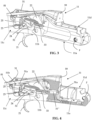
figure 2 is a partial perspective view of a preferred embodiment of a firearm according to the present invention in which only the frame is shown with a locking group mounted, in closed configuration with engaged safety; -
figure 3 is a perspective view of the parts of the firearm shown infigure 2 , in the closed configuration without engaged safety; -
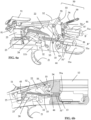
figure 4 is a perspective sectional view along a first vertical plane of the parts of the firearm shown infigure 3 ; -
figures 5 and 5a are respectively a perspective sectional view along a second vertical plane of the parts of the firearm shown infigure 3 and an enlarged detail thereof; -
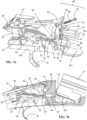
figures 6a and 6b are respectively a perspective view with some parts removed for clarity of illustration and a sectioned view in side elevation of the frame of the firearm offigure 2 , in closed configuration without engaged safety; -
figures 7a and 7b are respectively a perspective view with some parts removed for clarity of illustration and a sectioned view in side elevation of the frame of the firearm offigure 2 , in open configuration; -
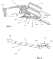
figure 8 is a perspective sectional view of some components of the firearm in open configuration with the recocking group shown; and -
figure 9 is a perspective view of the recocking group offigure 8 . - For the illustration of the drawings, use is made in the following description of identical numerals or symbols to indicate construction elements with the same function. Moreover, for clarity of illustration, certain references may not be repeated in all drawings.
- While the invention is susceptible to various modifications and alternative constructions, certain preferred embodiments are shown in the drawings and are described hereinbelow in detail. It must in any case be understood that there is no intention to limit the invention to the specific embodiment illustrated, but, on the contrary, the invention intends covering all the modifications, alternative and equivalent constructions that fall within the scope of the invention as defined in the claims.
- The use of "for example", "etc.", "or" indicates non-exclusive alternatives without limitation unless otherwise indicated. The use of "comprises" and "includes" means "comprises or includes, but not limited to", unless otherwise indicated.
- In addition, measurements, values, shapes and geometric references (such as perpendicularity and parallelism), when associated with words such as "about" or other similar terms such as "almost" or "substantially", are to be understood as "unless there are measurement errors" or "unless there are inaccuracies due to production and/ or manufacturing errors" and, above all, "unless there is a slight deviation from the value, measurement, shape or geometric reference to which it is associated".
- Moreover, the use of terms such as "first", "second", "main" and "secondary" does not necessarily identify an order, a relationship priority or relative position; these terms can simply be used to distinguish between similar components.
- Last but not least, relative positioning terms such as "upper", "lower", "front", "rear" or "side" generally refer to the normal configuration of use, in this specific case to the grip configuration of the firearm in order to proceed with shooting.
- With reference to
figure 1 , a preferred embodiment of a firearm according to the present invention is illustrated, overall indicated with 10. - The
firearm 10, hereinafter for brevity's sake also "weapon 10", comprises aframe 11 to which astock 14 and abarrel group 12, illustrated inFig. 1 are mounted. Thestock 14 is mounted integrally with theframe 11, while thebarrel group 12 is mounted on theframe 11 in a tilting manner between a closed position in which thebarrel group 12 is partially housed in a seat defined at afront portion 11d of theframe 11 and extends in parallel to abase wall 11a of theframe 11, and an open position in which thebarrel group 12 is rotated with respect to the base of the frame 11 (seeFig. 2 ). In other words, theframe 11 identifies a fulcrum F around which thebarrel group 12 is hinged. - The
barrel group 12 comprises a structure delimiting at least one barrel extending along a longitudinal development axis A of the barrel. By way of example, but not limitation, in the embodiment illustrated inFig. 1 , thebarrel group 12 comprises two overlapping barrels extending along the longitudinal development axis A. However, in alternative embodiments, the barrel group may comprise a single barrel or two side-by-side barrels. - With reference to
Figs. 2-5 , theframe 11 houses therein atrigger device 20 configured to trigger the firing of an ammunition, asafety device 80 configured to act on thetrigger device 20 so as to disengage it, thereby preventing a firing of an ammunition regardless of the condition of thetrigger device 20, and aclosing device 30 configured to selectively prevent thebarrel group 12 from tilting with respect to theframe 11. - By way of example, the
trigger device 20 comprises at least onetrigger 21 movably mounted (for example rotatable or translatable) on theframe 11 to actuate a group of in chain-connected trigger elements and configured to act on at least one firing pin (not illustrated). In the illustrated embodiment, the group of trigger elements comprises arelease 23 stabilized by amass 25 and configured to move at least one sear 24, which in turn actuates arespective hammer 22 to act on the respective firing pin. The trigger device also comprises a recocking foot (not illustrated) configured to act on thehammer 22 to bring it from a released hammer condition, following the firing of an ammunition, into a cocked hammer condition, following the closing of thefirearm 10. Arecocking group 90 acts on the recocking foot which is described in detail below with reference toFigs. 8 and 9 . - The
safety device 80 comprises an actuation element made as a slider 51 (hereinafter also for brevity 'slider 51') arranged externally to theframe 11 at arear portion 11c of the frame and movable in translation in the direction towards a termination of therear portion 11c of the frame. - When the
slider 51 is made to translate, starting from a neutral position, illustrated inFigs. 3-6b , towards the termination of therear portion 11c of the frame (position illustrated inFig. 2 ), it indirectly cooperates with therelease 23 of thetrigger device 20 so as to decouple it from the sear 24, thus disengaging thetrigger device 20. - In detail, in the illustrated embodiment, the
slider 51 cooperates with the mass 25 that stabilizes therelease 23 so as to drag it at least partially along with it towards the termination of therear portion 11c of the frame when it is translated in this direction. This movement of themass 25 also causes a backward movement of therelease 23 which therefore disengages from the sear 24, as shown inFig. 2 , being no longer able to activate it following a movement of thetrigger 21. - There is also a
retention element 81, for example of the elastic type, arranged and configured to retain theslider 51 in the backward position located in proximity to the termination of therear portion 11c of the frame. To this end, theslider 51 comprises aportion 51a that extends internally to theframe 11 and comprises at least one protrudingpin 51b configured to releasably engage theretention element 81. - The closing
device 30 is configured to act between theframe 11 and thebarrel group 12, when thefirearm 10 is in the closed configuration; in particular, the closingdevice 30 is manoeuvrable between a locking position (illustrated inFigs. 6a and 6b ), in which it engages thebarrel group 12 to prevent the tilting with respect to theframe 11, and a release position (illustrated inFigs. 7a and 7b ), in which theclosing device 30 is disengaged from thebarrel group 12 and thebarrel group 12 is therefore free to rotate with respect to theframe 11. - In the illustrated embodiment, the closing
device 30 comprises at least one pair of clampingelements 31',31" with longitudinal development independent and separate from each other, visible in detail inFigs. 6a and7a . - As shown in
Figs. 4 and5 , the clampingelements 31',31" are at least partially received internally to theframe 11. The clampingelements 31',31" develop along a respective development axis B',B" of the clamping elements and are slidably received within theframe 11, along their own longitudinal development axis B',B". - In particular, the clamping
elements 31',31" are housed inside theframe 11 in a sliding manner between a position in which afirst end part 31a of the clampingelement 31',31", preferably tip-shaped, protrudes towards a housing seat of thebarrel group 12 located at thefront portion 11d of the frame (shown inFigs. 3-6b ) and a position in which the first end part is retracted and substantially does not protrude into the housing seat of the barrel group 12 (shown inFigs. 7a and 7b ). Consequently, when thebarrel group 12 is in the closed position, as illustrated in detail inFig. 6b , the clampingelements 31',31" engage, each with its ownfirst end part 31a, arespective hook 13 made on thebarrel group 12. Otherwise, when theclosing device 30 is actuated to open, the clampingelements 31',31" do not engage therespective hooks 13 and thebarrel group 12 is free to tilt. - The closing
device 30 also comprises a pair ofbuffers respective side 11b of therear portion 11c of theframe 11. Eachbuffer support 32 carrying a firstelastic element 33, interposed between thesupport 32 and arespective clamping element 31',31" and exerting an axial thrust force on therespective clamping element 31',31" substantially in parallel to and/or substantially along the longitudinal development axis B',B" thereof, so that, in the absence of applied forces, the clampingelements 31',31" protrude from theframe 11 with theirfirst end part 31a, towards the housing seat of thebarrel group 12. - The closing
device 30 further comprises amanoeuvring group 50 configured to impart to each clampingelement 31',31" of the pair of clamping elements a force in opposition to a force exerted on each clampingelement 31',31" by therespective buffer - In the illustrated embodiment, the
manoeuvring group 50 advantageously coincides with theactuation element 51 of thesafety device 80 made as a slider. - The
slider 51 is in fact coupled also to afirst lever 52 of alever mechanism frame 11 so as to advance it towards thefront portion 11d of theframe 11 up to an engagement position. In the engagement position, the firstinternal lever 52 engages a releasable locking rod 57 (shown inFigs. 6a and7a ) configured to retain the firstinternal lever 52 in the advanced engagement position. - The first
internal lever 52 is in turn hinged to a pair of secondinternal levers 53 of thelever mechanism internal lever 52 is coupled to the secondinternal levers 53 so that an advancement of the firstinternal lever 52 towards the engagement position causes a rotation of the secondinternal levers 53 around apivot 55 and at the same time around arespective fulcrum pin 54 placed in an intermediate position with respect to the extension of the respective secondinternal lever 53. - Each of the second
internal levers 53 engages, at its own second end, arespective clamping element 31',31" so that, when the secondinternal levers 53 are brought into rotation by the advancement of the firstinternal lever 52, the clampingelements 31',31" are made to translate in opposition to the force exerted by therespective buffer elements 31',31" move backward, retracting the respectivefirst end part 31a and decoupling it from the correspondinghook 13. - To this end, the second end of each second
internal lever 53 engages agroove 44 located at a second end part of therespective clamping element 31',31" opposite the first 31a so as to drag said clampingelement 31',31" into translation when the secondinternal lever 53 is brought into rotation. - The releasable locking
rod 57 is housed in theframe 11 according to an arrangement substantially orthogonal to thebase wall 11a of theframe 11 and movably along its own rod axis. The releasable lockingrod 57 is normally kept in a position away from thebase wall 11a by a secondelastic element 58. The advancement movement of the firstinternal lever 52 causes a temporary displacement of the releasable lockingrod 57 towards thebase wall 11a, which takes on again the distanced position once the firstinternal lever 52 reaches the engagement position. In such a configuration, the lockingrod 57 retains the firstinternal lever 52 in the engagement position. In fact, the firstinternal lever 52 is in abutment against a step portion obtained at a free end of the lockingrod 57. - In order to release the first
internal lever 52 from the engagement position, the closingdevice 50 comprises arelease rod 59, housed in theframe 11 according to an oblique arrangement with respect to thebase wall 11a of theframe 11 and movably along its own rod axis, between a configuration of greater protrusion from theframe 11 at the housing seat of the barrel group 12 (shown inFigs. 3 and 4 ) and a configuration of lesser or no protrusion. When brought into the position of lesser or no protrusion, therelease rod 59 engages the releasable lockingrod 57, displacing it from the distanced position and releasing in this way the firstinternal lever 52 from this lockingrod 57. - The
release rod 59 is normally held in the position of greater protrusion by a thirdelastic element 56 and is brought into the position of lesser or no protrusion by thebarrel group 12, when this engages its own housing seat provided at thefront portion 11d of the frame. In this way, advantageously, by bringing thebarrel group 12 into the closed position there is an automatic release of the firstinternal lever 52 from the lockingrod 57. The clampingelements 31',31" are therefore no longer forced by the set ofinternal levers first end part 31a retracting; on the contrary they are returned by the respective firstelastic elements 33 into the protruding locking position, with coupling with thehooks 13 of thebarrel group 12. This also results in an automatic return of theinternal levers - To ensure that in the open position of the
barrel group 12 the trigger device is inoperative, the slider-like actuation element 51 in itslower portion 51a extending internally to theframe 11 is shaped so as to cooperate with asafety element 45 arranged internally to the frame 11 (shown in detail inFigs. 6b and7b ). Thesafety element 45 is made as a sheet metal and has an L-shaped profile. Thesafety element 45 is arranged in the frame in an oscillatable manner between a rest position in which thesafety element 45 does not interfere with the group of trigger elements (seeFig. 6b ) and a safety position in which it interferes with the group of trigger elements so as to make it inoperative (seeFig. 7b ). Advantageously, the slider-like actuation element 51 and thesafety element 45 cooperate so that an advancement of theslider element 51 in the direction towards thefront portion 11d of the frame causes an oscillation of thesafety element 45 such as to bring it into the safety position. -
Fig. 8 shows theframe 11 and part of thebarrel group 12 in which, for clarity of illustration, only therecocking group 90 is illustrated. Therecocking group 90 comprises arecocking forend 91 housed in the base wall 10a of thefront portion 11d of the frame in a sliding manner between therear portion 11c and thefront portion 11d of the frame. - A
first end 91a of therecocking forend 91 is configured to cooperate with the recocking foot of thetrigger device 20 so that it brings thehammer 22 into the cocked hammer condition. In particular, therecocking forend 91 cooperates with the recocking foot when it is moved towards theframe bottom 11c, following a rotation of thebarrel group 12 to return it to the closed configuration. - The
recocking group 90 further comprises a fourthelastic element 92 configured to maintain therecocking forend 91 in a disengagement position from the recocking foot of thetrigger group 20. - The
recocking group 90 finally comprises aninsert 93, illustrated in detail inFig. 9 , interposed between therecocking forend 91 and thebarrel group 12, in particular arranged at asecond end 91b of therecocking forend 91 opposite the first one 91a. Theinsert 93 is configured to transfer to therecocking forend 91 a thrust in the direction of thebarrel bottom 11c when thebarrel group 12 passes from the open configuration to the closed configuration. Theinsert 93 engages thebarrel group 12 with a slide-shapedportion 93a thereof, facilitating the closing operations of thefirearm 10 and thus reducing the wear that usually characterizes theforend 91 of therecocking group 90.
Claims (10)
- Firearm (10) comprising at least:- a frame (11); and- a barrel group (12) comprising at least one barrel, the barrel group (12) being mounted in a tilting manner with respect to the frame (11),wherein the frame (11) houses at least one trigger device (20) configured to trigger the firing of an ammunition, a safety device (80) configured to act on the trigger device (20) so as to selectively disengage it, and a closing device (30) configured to act between the frame (11) and the barrel group (12) so as to selectively prevent the barrel group (12) from tilting with respect to the frame (11),characterized in that it comprises an actuation element (51) configured to selectively activate the safety device (80) and the closing device (30).
- Firearm (10) according to claim 1, wherein the actuation element (51) is made as a slider arranged externally to the frame (11) and movable in translation, preferably arranged at a rear portion (11c) of the frame and/or movable alternately in a direction towards a termination of the rear portion (11c) of the frame and in a direction towards a front portion (11d) of the frame.
- Firearm (10) according to claim 1 or 2, wherein the trigger device (20) comprises a group of trigger elements connected in chain and configured to act on at least one firing pin, wherein the actuation element (51) interferes with the group of trigger elements so as to make it inoperative both when the actuation element (51) is translated in the direction of the rear portion (11c), and when the actuation element (51) is translated in the direction towards the front portion (11d) of the frame.
- Firearm (10) according to any one of claims 1 to 3, wherein the actuation element (51) cooperates with a safety element (45), preferably "L"-shaped, housed internally to the frame (11) in a tilting manner between a rest position in which the safety element (45) does not interfere with the group of trigger elements and a safety position in which the safety element (45) interferes with the group of trigger elements so as to make it inoperative, the safety element (45) being brought into the safety position by a translation of the actuation element (51) in the direction towards the front portion (11d) of the frame.
- Firearm (10) according to any one of the preceding claims, wherein the closing device (30) comprises:- at least one pair of clamping elements (31',31") with longitudinal development and independent of each other, the clamping elements (31',31") being slidably housed inside the frame (11), each along its own longitudinal development axis (B',B"); and- at least one pair of buffers (32,33) each coupled to a respective clamping element (31',31") so as to exert an axial thrust force on the respective clamping element (31',31") substantially in parallel to and/or substantially along the respective longitudinal development axis (B',B"); and- a manoeuvring group (50) configured to impart to each clamping element (31',31") of the pair of clamping elements (31',31") a force in opposition to a force exerted by a buffer (32,33) on the respective clamping element (31',31"), the manoeuvring group (50) being actuated by the actuation element (51).
- Firearm (10) according to claim 5, wherein the manoeuvring group (50) comprises a lever mechanism (52,53) inside the frame (11) that engages the pair of clamping elements (31',31"), and wherein the actuation element (51) is coupled to the lever mechanism (52,53), so that an advancement of the actuation element (51) towards a front portion (11d) of the frame causes a translation of the pair of clamping elements (31',31 ") in opposition to the force exerted by the respective buffers (32,33).
- Firearm (10) according to claim 6, wherein the lever mechanism (52,53) cooperates with a releasable locking rod (57) housed in the frame (11) movably along its own rod axis and configured to retain the lever mechanism (52,53) in an engagement position corresponding to a position of maximum translation of the pair of clamping elements (31',31") in opposition to the force exerted by the respective buffers (32,33).
- Firearm (10) according to claim 7, wherein the releasable locking rod (57) cooperates with a release rod (59) housed in the frame (11) movably along its own rod axis, between a configuration of greater protrusion from the frame (11) at a housing seat of the barrel group (12) located at a front portion (11d) of the frame and a configuration of lesser or no protrusion from the housing seat of the barrel group (12), wherein in the configuration of greater protrusion the release rod (59) does not cooperate with the releasable locking rod (57) and in the configuration of lesser or no protrusion the release rod (59) cooperates with the releasable locking rod (57) to decouple it from the lever mechanism (52,53).
- Firearm (10) according to any one of claims 5 to 8, wherein each buffer (32,33) of the pair of buffers (32,33) is mounted on a respective side (11b) of a rear portion (11c) of the frame (11).
- Firearm (10) according to any one of the preceding claims, wherein the trigger device (20) comprises a hammer (22) configured to switch from a cocked hammer condition to a released hammer condition following an actuation of the trigger device (22), and wherein it is comprised a recocking group (90) configured to act on the trigger device (20) so as to switch the hammer (22) from the released hammer condition to the cocked hammer condition, the recocking group (90) comprising a recocking forend (91) housed in a base wall (10a) of a front portion (11d) of the frame in a sliding manner between a rear portion (11c) and the front portion (11d) of the frame and an insert (93) interposed between the recocking forend (91) and the barrel group (12), the insert (93) comprising a slide-shaped portion (93a) engaging the barrel group (12).
Priority Applications (2)
| Application Number | Priority Date | Filing Date | Title |
|---|---|---|---|
| EP23425063.7A EP4563930B1 (en) | 2023-12-01 | 2023-12-01 | Break-barrel firearm with improved manageability |
| US18/962,560 US12546546B2 (en) | 2023-12-01 | 2024-11-27 | Break-barrel firearm with improved manageability |
Applications Claiming Priority (1)
| Application Number | Priority Date | Filing Date | Title |
|---|---|---|---|
| EP23425063.7A EP4563930B1 (en) | 2023-12-01 | 2023-12-01 | Break-barrel firearm with improved manageability |
Publications (2)
| Publication Number | Publication Date |
|---|---|
| EP4563930A1 true EP4563930A1 (en) | 2025-06-04 |
| EP4563930B1 EP4563930B1 (en) | 2026-07-29 |
Family
ID=89767769
Family Applications (1)
| Application Number | Title | Priority Date | Filing Date |
|---|---|---|---|
| EP23425063.7A Active EP4563930B1 (en) | 2023-12-01 | 2023-12-01 | Break-barrel firearm with improved manageability |
Country Status (2)
| Country | Link |
|---|---|
| US (1) | US12546546B2 (en) |
| EP (1) | EP4563930B1 (en) |
Citations (1)
| Publication number | Priority date | Publication date | Assignee | Title |
|---|---|---|---|---|
| US5459956A (en) * | 1993-12-30 | 1995-10-24 | Remington Arms Company, Inc. | Firearm ejector system |
Family Cites Families (6)
| Publication number | Priority date | Publication date | Assignee | Title |
|---|---|---|---|---|
| US495298A (en) * | 1893-04-11 | Ward george parry | ||
| DE3735773A1 (en) * | 1987-10-22 | 1989-05-03 | Dynamit Nobel Ag | RIFLE WITH SAFETY RELAXATION SYSTEM |
| DE4000819A1 (en) * | 1990-01-13 | 1991-07-18 | Dynamit Nobel Ag | REMOVABLE RIFLE LOCK |
| FR2803909B1 (en) * | 2000-01-14 | 2002-04-05 | Jean Causse | OVERLOCKING TUNNEL HUNTING GUN |
| DE102007044993B3 (en) * | 2007-09-20 | 2009-01-08 | Blaser Finanzholding Gmbh | Tipping rifle with block closure |
| ITBS20120029A1 (en) * | 2012-02-29 | 2013-08-30 | Beretta Armi Spa | FIREARMS WITH TILTING ROD GROUP |
-
2023
- 2023-12-01 EP EP23425063.7A patent/EP4563930B1/en active Active
-
2024
- 2024-11-27 US US18/962,560 patent/US12546546B2/en active Active
Patent Citations (1)
| Publication number | Priority date | Publication date | Assignee | Title |
|---|---|---|---|---|
| US5459956A (en) * | 1993-12-30 | 1995-10-24 | Remington Arms Company, Inc. | Firearm ejector system |
Also Published As
| Publication number | Publication date |
|---|---|
| US12546546B2 (en) | 2026-02-10 |
| EP4563930B1 (en) | 2026-07-29 |
| US20250180311A1 (en) | 2025-06-05 |
Similar Documents
| Publication | Publication Date | Title |
|---|---|---|
| US10697721B2 (en) | Charging handle with push rod | |
| EP3155348B1 (en) | Firearm receiver with forward assist and bolt catch release | |
| US9488424B1 (en) | Charging handle with cog and spring | |
| EP3737907B1 (en) | Modular magazine well insert system for firearm | |
| EP3237828B1 (en) | Safety mechanism for firearm | |
| US10126086B2 (en) | Ambidextrous safety for a firearm | |
| US5519954A (en) | Ambidextrous magazine release mechanism for firearms | |
| US20060123683A1 (en) | Ambidextrous magazine catch for firearms | |
| US11578939B2 (en) | Safety mechanism for firearms | |
| CA2545898A1 (en) | Locking lever, and semiautomatic weapon comprising said locking lever | |
| US12546546B2 (en) | Break-barrel firearm with improved manageability | |
| FI4196737T3 (en) | CARTRIDGE MAGAZINE LOCK | |
| EP4166890B1 (en) | Rifle with recoil group | |
| US12339080B2 (en) | Safety mechanism for a pistol | |
| US1446763A (en) | Firearm | |
| US11796267B2 (en) | Carbine with charging handle assembly | |
| US5459956A (en) | Firearm ejector system | |
| US4328635A (en) | Firearm having multiple barrels movable together to one side | |
| EP4563932B1 (en) | Break-barrel firearm | |
| US4380881A (en) | High speed firing mechanism for single-trigger double-barreled firearm | |
| EP4563931A1 (en) | Break-barrel firearm with mechanical extraction assembly |
Legal Events
| Date | Code | Title | Description |
|---|---|---|---|
| PUAI | Public reference made under article 153(3) epc to a published international application that has entered the european phase |
Free format text: ORIGINAL CODE: 0009012 |
|
| STAA | Information on the status of an ep patent application or granted ep patent |
Free format text: STATUS: THE APPLICATION HAS BEEN PUBLISHED |
|
| AK | Designated contracting states |
Kind code of ref document: A1 Designated state(s): AL AT BE BG CH CY CZ DE DK EE ES FI FR GB GR HR HU IE IS IT LI LT LU LV MC ME MK MT NL NO PL PT RO RS SE SI SK SM TR |
|
| STAA | Information on the status of an ep patent application or granted ep patent |
Free format text: STATUS: REQUEST FOR EXAMINATION WAS MADE |
|
| 17P | Request for examination filed |
Effective date: 20251121 |
|
| GRAP | Despatch of communication of intention to grant a patent |
Free format text: ORIGINAL CODE: EPIDOSNIGR1 |
|
| STAA | Information on the status of an ep patent application or granted ep patent |
Free format text: STATUS: GRANT OF PATENT IS INTENDED |
|
| INTG | Intention to grant announced |
Effective date: 20260225 |
|
| GRAS | Grant fee paid |
Free format text: ORIGINAL CODE: EPIDOSNIGR3 |
|
| GRAA | (expected) grant |
Free format text: ORIGINAL CODE: 0009210 |
|
| STAA | Information on the status of an ep patent application or granted ep patent |
Free format text: STATUS: THE PATENT HAS BEEN GRANTED |
|
| AK | Designated contracting states |
Kind code of ref document: B1 Designated state(s): AL AT BE BG CH CY CZ DE DK EE ES FI FR GB GR HR HU IE IS IT LI LT LU LV MC ME MK MT NL NO PL PT RO RS SE SI SK SM TR |
|
| REG | Reference to a national code |
Ref country code: CH Ref legal event code: F10 Free format text: ST27 STATUS EVENT CODE: U-0-0-F10-F00 (AS PROVIDED BY THE NATIONAL OFFICE) Effective date: 20260729 |
|
| REG | Reference to a national code |
Ref country code: DE Ref legal event code: R096 Ref document number: 602023020464 Country of ref document: DE |