EP4563907A1 - Air conditioner - Google Patents
Air conditioner Download PDFInfo
- Publication number
- EP4563907A1 EP4563907A1 EP22956204.6A EP22956204A EP4563907A1 EP 4563907 A1 EP4563907 A1 EP 4563907A1 EP 22956204 A EP22956204 A EP 22956204A EP 4563907 A1 EP4563907 A1 EP 4563907A1
- Authority
- EP
- European Patent Office
- Prior art keywords
- air duct
- pulse
- pulsed
- mounting base
- wire
- Prior art date
- Legal status (The legal status is an assumption and is not a legal conclusion. Google has not performed a legal analysis and makes no representation as to the accuracy of the status listed.)
- Pending
Links
Images









Classifications
-
- F—MECHANICAL ENGINEERING; LIGHTING; HEATING; WEAPONS; BLASTING
- F24—HEATING; RANGES; VENTILATING
- F24F—AIR-CONDITIONING; AIR-HUMIDIFICATION; VENTILATION; USE OF AIR CURRENTS FOR SCREENING
- F24F1/00—Room units for air-conditioning, e.g. separate or self-contained units or units receiving primary air from a central station
- F24F1/0007—Indoor units, e.g. fan coil units
- F24F1/0059—Indoor units, e.g. fan coil units characterised by heat exchangers
- F24F1/0063—Indoor units, e.g. fan coil units characterised by heat exchangers by the mounting or arrangement of the heat exchangers
-
- F—MECHANICAL ENGINEERING; LIGHTING; HEATING; WEAPONS; BLASTING
- F24—HEATING; RANGES; VENTILATING
- F24F—AIR-CONDITIONING; AIR-HUMIDIFICATION; VENTILATION; USE OF AIR CURRENTS FOR SCREENING
- F24F8/00—Treatment, e.g. purification, of air supplied to human living or working spaces otherwise than by heating, cooling, humidifying or drying
- F24F8/20—Treatment, e.g. purification, of air supplied to human living or working spaces otherwise than by heating, cooling, humidifying or drying by sterilisation
-
- F—MECHANICAL ENGINEERING; LIGHTING; HEATING; WEAPONS; BLASTING
- F24—HEATING; RANGES; VENTILATING
- F24F—AIR-CONDITIONING; AIR-HUMIDIFICATION; VENTILATION; USE OF AIR CURRENTS FOR SCREENING
- F24F2221/00—Details or features not otherwise provided for
- F24F2221/22—Cleaning ducts or apparatus
Definitions
- the present disclosure relates to the field of air conditioning device technologies, and more particularly, to an air conditioner.
- one purpose of the present disclosure is to provide an air conditioner.
- the pulsed sterilization module By disposing a pulsed sterilization module on an air duct component, the pulsed sterilization module emits pulsed light which irradiates a heat exchanger component and the air duct component to perform purification and sterilization on the heat exchanger component and the air duct component.
- a pulse lamp tube extends in an up-down direction, enabling an irradiation range of the pulsed light to be wider and a sterilization range to be wider.
- the air conditioner includes: a casing having an air inlet and an air outlet; a heat exchanger component disposed in the casing; an air duct component disposed in the casing, an air duct chamber being defined between the heat exchanger component and the air duct component and extending in an up-down direction; and a pulsed sterilization module disposed at the air duct component and adapted to emit pulsed light into the air duct chamber, the pulsed sterilization module being provided with a pulse lamp tube extending in the up-down direction.
- the pulsed sterilization module can emit the pulsed light into the air duct chamber.
- the pulsed light irradiates the heat exchanger component and the air duct component to purify and sterilize the heat exchanger component and the air duct component.
- the pulse lamp tube extends in the up-down direction, enabling the irradiation range of the pulsed light to be wider and the sterilization range to be wider.
- the pulsed sterilization module is located at a middle part of the air duct component in a left-right direction.
- the pulsed sterilization module is located at a side of the air duct component adjacent to the heat exchanger component.
- the air duct component includes an air duct volute and two impellers mounted at the air duct volute.
- the air duct chamber includes two air duct cavities defined between the air duct volute and the heat exchanger component and arranged in a left-right direction, the two impellers being respectively located in the two air duct cavities, and the pulsed sterilization module being located between the two air duct cavities.
- the air duct component is located at a front side of the heat exchanger component.
- the air duct volute includes a volute body and an air duct partition connected to a rear side of the air duct volute, the air duct partition abutting with the heat exchanger component to divide the air duct chamber into the two air duct cavities, and the pulsed sterilization module being disposed in the air duct partition.
- the pulsed sterilization module is disposed at an upper part of the air duct partition.
- the pulsed sterilization module is disposed at a top of the air duct partition, the air duct chamber being divided into the two air duct cavities by the pulsed sterilization module and the air duct partition.
- an outer contour shape of a cross-section of the pulsed sterilization module is the same as an outer contour shape of a cross-section of the air duct partition.
- the pulsed sterilization module includes a pulse mounting base disposed at the air duct partition.
- the pulse lamp tube is disposed at the pulse mounting base and located at a rear side of the pulse mounting base.
- the pulse mounting base and the air duct partition are integrally formed.
- the pulse mounting base is provided with two first fixation bases spaced apart from each other in the up-down direction.
- the pulsed sterilization module further includes two second fixation bases spaced apart from each other in the up-down direction.
- the two second fixation bases and the two first fixation bases respectively define two limiting holes, an upper end and a lower end of the pulse lamp tube passing through the two limiting holes, respectively; and each of the two second fixation bases is detachably connected to a corresponding first fixation base of the two first fixation bases.
- the air duct partition, the pulse mounting base, and the two first fixation bases are integrally formed.
- the two first fixation bases and the two second fixation bases define two wire-passing holes, respectively.
- the pulse lamp tube has a first lead-out wire at an upper end of the pulse lamp tube, the first lead-out wire being led out upwardly.
- the pulse lamp tube has a second lead-out wire at a lower end of the pulse lamp tube, the second lead-out wire is led from a side of the pulse mounting base in a left-right direction of the pulse mounting base to a side of the pulse mounting base away from the pulse lamp tube, and then is led out upwardly.
- the pulse mounting base is provided with a first wiring clip at an upper end of the pulse mounting base, the first wiring clip being located above the pulse lamp tube, and the first lead-out wire passing through the first wiring clip.
- the pulse mounting base is provided with a plurality of second wiring clips at the side of the pulse mounting base away from the pulse lamp tube, the plurality of second wiring clips being arranged at intervals in the up-down direction, and the second lead-out wire passing through the plurality of second wiring clips.
- the pulse mounting base has a wire-passing notch at a left side wall or a right side wall of the pulse mounting base, the wire-passing notch being configured to allow the second lead-out wire to pass through the wire-passing notch.
- the wire-passing notch includes: a guide segment penetrating the left side wall or the right side wall of the pulse mounting base; a wire-passing body, the second lead-out wire penetrating the wire-passing body; and an constricted segment located between the guide segment and the wire-passing body, a width of the constricted segment being smaller than a width of the guide segment and a width of the wire-passing body.
- the pulsed sterilization module further includes a protective cover that is transparent.
- the protective cover is connected to the rear side of the pulse mounting base.
- a receiving space is defined between the protective cover and the pulse mounting base and is configured to receive the pulse lamp tube, a fastener sequentially penetrating through the protective cover, the pulse mounting base, and then extending into the volute body, to enable the pulsed sterilization module to be mounted and fixed.
- an air conditioner includes a casing 10, a heat exchanger component 40, an air duct component 30, and a pulsed sterilization module 20.
- the casing 10 has an air inlet 13 and an air outlet, which are in communication with an indoor environment to facilitate airflow circulation.
- the heat exchanger component 40 is disposed in the casing 10.
- the air duct component 30 is disposed in the casing 10.
- an air duct chamber 34 is defined between the heat exchanger component 40 and the air duct component 30 and extends in an up-down direction.
- the pulsed sterilization module 20 is disposed at the air duct component 30 and adapted to emit pulsed light into the air duct chamber 34.
- the pulsed sterilization module 20 can emit pulsed light having higher energy.
- the pulsed light irradiates on a surface of a microorganism in the air duct chamber 34, which can change and inactivate the substances in the microorganism. In this way, bacteria and viruses in the air duct chamber 34 can be completely killed, and thus air in the air duct chamber 34 can be purified and sterilized. A better sterilization effect and a higher sterilization efficiency can be realized.
- some harmful gases in the air (such as VOC gases) can also be decomposed under irradiation of the pulsed light, purifying the air and improving quality of air blown into the indoor environment.
- the air duct chamber 34 extends in the up-down direction.
- the air duct component 30 and the heat exchanger component 40 both extend in the up-down direction.
- the pulse lamp tube 23 in the pulsed sterilization module 20 extends in the up-down direction.
- the pulsed light emitted by the pulsed sterilization module 20 can irradiate the heat exchanger component 40 and the air duct component 30 simultaneously, which can purify and sterilize the heat exchanger component 40 and the air duct component 30, and can purify and sterilize the air passing through the air duct chamber 34. In this way, a sterilization range of the pulsed light can be larger and the higher sterilization efficiency can be ensured.
- the air conditioner may be a split-type air conditioner, such as a split floor-standing air conditioner.
- the air conditioner includes an air conditioner indoor unit 100 and an air conditioner outdoor unit.
- the air conditioner indoor unit 100 includes the casing 10, the heat exchanger component 40, the air duct component 30, and the pulsed sterilization module 20 described above.
- the air conditioner indoor unit 100 may be a floor-standing cabinet.
- the casing 10 may include a rear cover 11, a top cover 14, an air outlet frame 15, a lower panel 16, and a base 17.
- the air outlet frame 15 is located at an upper side of the lower panel 16.
- the air outlet frame 15 and the lower panel 16 are both located at a front side of the rear cover 11.
- the top cover 14 covers a top of the air outlet frame 15 and a top of the rear cover 11.
- the base 17 is located at a bottom of a lower frame and a bottom of the rear cover 11.
- the air outlet frame 15 may be detachably connected to the rear cover 11.
- the lower panel 16 may be detachably connected to the rear cover 11.
- the top cover 14 may be detachably connected to the air outlet frame 15 and the rear cover 11.
- the rear cover 11 may have the air inlet 13, which in communication with the indoor environment.
- An air inlet grille 12 may be provided at the air inlet 13.
- the heat exchanger component 40 may be located at a front side of the air inlet 13.
- the air duct component 30 may be located at a front side of the heat exchanger component 40.
- the air outlet frame 15 may be located at a front side of the air duct component 30.
- the air outlet frame 15 includes a frame body 151, an upper panel 152, and an air deflector 153. Two air outlets are defined between a left side and a right side of the upper panel 152 and the rear cover 11, respectively.
- the two air outlets are located at the left side of the upper panel 152 and the right side of the upper panel 152, respectively.
- the air outlet frame 15 further includes the air deflector 153 located at the air outlet.
- the air deflector 153 is rotatably connected to the upper panel 152 to open and close the air outlet.
- the air outlet is also in communication with the indoor environment.
- the pulsed sterilization module 20 can emit the pulsed light into the air duct chamber 34.
- the pulsed light irradiates on the heat exchanger component 40 and the air duct component 30 to purify and sterilize the heat exchanger component 40 and the air duct component 30.
- quality of air passing through the heat exchanger component 40 and the air duct component 30 can be improved, thereby improving indoor air quality and comfort.
- the pulse lamp tube 23 extends in the up-down direction, a range of irradiation of the pulsed light can be wider, and thus a range of sterilization can be wider.
- the pulsed sterilization module 20 is located at a middle part of the air duct component 30 in a left-right direction. Pulsed light emitted by the pulsed sterilization module 20 can be uniformly irradiated in the air duct chamber 34, resulting in a wider sterilization range.
- the pulsed sterilization module 20 is located at a side of the air duct component 30 adjacent to the heat exchanger component 40.
- the pulsed light emitted by the pulsed sterilization module 20 can be irradiated on the heat exchanger component 40 to sterilize the heat exchanger component 40, or can purify and sterilize the air passing through the heat exchanger component 40 to improve the air quality.
- the air duct component 30 includes an air duct volute 3 and two impellers 33 mounted at the air duct volute 3.
- the air duct chamber 34 includes two air duct cavities 35 defined between the air duct volute 3 and the heat exchanger component 40, and arranged in the left-right direction.
- the two impellers 33 may be arranged in the left-right direction and respectively located in the two air duct cavities 35.
- the pulsed sterilization module 20 is located between the two air duct cavities 35.
- the pulsed light emitted by the pulsed sterilization module 20 can be uniformly irradiated into a left air duct cavity 35 and a right air duct cavity 35. In this way, the pulsed sterilization module 20 can simultaneously sterilize the two air duct cavities 35, and can also sterilize the air duct volute 3 and the two impellers 33, resulting in the wider sterilization range and a higher sterilization efficiency.
- the two impellers 33 are a first impeller 331 and a second impeller 332, respectively.
- the two air duct cavities 35 are a first air duct cavity 351 and a second air duct cavity 352, respectively.
- the first air duct cavity 351 may be located at a left side of the second air duct cavity 352.
- the first impeller 331 is located in the first air duct cavity 351, and the second impeller 332 is located in the second air duct cavity 352.
- the first air duct cavity 351 may be in communication with an air outlet at a left side of the upper panel 152. Air in the first air duct cavity 351 may be blown out through the air outlet at the left side of the upper panel 152.
- the second air duct cavity 352 may be in communication with an air outlet at a right side of the upper panel 152. Air in the second air duct cavity 352 may be blown out through the air outlet at the right side of the upper panel 152.
- the air duct component 30 is located at a front side of the heat exchanger component 40.
- the air duct volute 3 includes a volute body 32 and an air duct partition 31 connected to a rear side of the air duct volute 3.
- the air duct partition 31 abuts with the heat exchanger component 40 to divide the air duct chamber 34 into the two air duct cavities 35, which can prevent air from flowing between the two air duct cavities 35, thereby ensuring uniform air velocity on two sides.
- the pulsed sterilization module 20 is disposed in the air duct partition 31.
- the pulsed sterilization module 20 By mounting the pulsed sterilization module 20 in the air duct partition 31, mounting and fixation of the pulsed sterilization module 20 can be convenient, and the pulsed sterilization module 20 can be located between the two air duct cavities 35.
- the pulsed light emitted by the pulsed sterilization module 20 can be uniformly irradiated in the two air duct cavities 35 to purify and sterilize the two air duct cavities 35, resulting in the higher sterilization efficiency.
- the pulsed sterilization module 20 may be disposed at an upper part of the air duct partition 31.
- the pulsed sterilization module 20 may be disposed at a middle part of the air duct partition 31 in the up-down direction.
- the pulsed sterilization module 20 may be disposed at a lower part of the air duct partition 31.
- a plurality of pulsed sterilization modules 20 may be arranged at intervals in the up-down direction of the air duct partition 31, in such a manner that the irradiation range of the pulsed light is further increased and the sterilization range is larger.
- the volute body 32 may include a first volute body 321 and a second volute body 322 that are arranged in the left-right direction.
- the first volute body 321 is connected to the second volute body 322.
- the first impeller 331 may be mounted in the first volute body 321.
- the second impeller 332 may be mounted in the second volute body 322.
- the first volute body 321 may be located at a left side of the second volute body 322.
- the air duct partition 31 is located in the middle part of the air duct component 30 in the left-right direction.
- the air duct partition 31 abuts with a middle part of the heat exchanger component 40 in the left-right direction.
- the first air duct cavity 351 may be defined between the air duct partition 31, the heat exchanger component 40, and the first volute body 321.
- the second air duct cavity 352 may be defined between the air duct partition 31, the heat exchanger component 40, and the second volute body 322.
- the air duct component 30 may further include a first motor 36 disposed at a top of the first volute body 321 and connected to the first impeller 331 to drive the first impeller 331 to rotate, and a second motor 37 disposed at a top of the second volute body 322 and connected to the second impeller 332 to drive the second impeller 332 to rotate.
- the pulsed sterilization module 20 may be disposed at the upper part of the air duct partition 31.
- the pulsed sterilization module 20 may emit the pulsed light in all directions.
- the pulsed light may irradiate on the two air duct cavities 35, purifying and sterilizing the air passing through the two air duct cavities 35.
- the pulsed light may irradiate on an upper part of the heat exchanger component 40 and an upper part of the air duct component 30 to purify and sterilize the upper part of the heat exchanger component 40 and the upper part of the air duct component 30.
- the pulsed sterilization module 20 may be disposed at the middle part of the air duct partition 31 (not illustrated).
- the pulsed sterilization module 20 may emit the pulsed light in all directions, and may irradiate on the two air duct cavities 35, purifying and sterilizing the air passing through the two air duct cavities 35.
- the pulsed light may irradiate on a middle part of the heat exchanger component 40 and a middle part of the air duct component 30 to purify and sterilize the middle part of the heat exchanger component 40 and the middle part of the air duct component 30.
- the pulsed sterilization module 20 may also be disposed at a bottom of the air duct partition 31 (not illustrated).
- the pulsed sterilization module 20 may emit the pulsed light in all directions, and may irradiate the two air duct cavities 35, purifying and sterilizing the air passing through the two air duct cavities 35.
- a lower end the heat exchanger component 40 and a water collection tray at a lower side of the heat exchanger component 40 are more prone to bacterial growth.
- the pulsed sterilization module 20 can emit the pulsed light towards a bottom of the heat exchanger component 40 to purify and sterilize the bottom of the heat exchanger component 40 and the water collection tray at the lower side of the heat exchanger component 40.
- This arrangement allows the pulsed light to directly irradiate regions with higher concentrations of bacteria, enhancing the sterilization efficiency and a sterilization effect of the pulsed sterilization module 20.
- the pulsed sterilization module 20 may be disposed at a top of the air duct partition 31.
- the pulsed sterilization module 20 may abut with the heat exchanger component 40.
- the air duct partition 31 abuts with the heat exchanger component 40.
- the air duct chamber 34 is divided into the two air duct cavities 35 by the pulsed sterilization module 20 and the air duct partition 31, which can effectively prevent air from flowing between the left air duct cavity 35 and the right air duct cavity 35, thereby ensuring the uniform air velocity on two sides.
- a material for making the air duct partition 31 can be saved, and a space occupied by the pulsed sterilization module 20 in the casing 10 can be reduced, and thus a space in the casing 10 can be saved.
- an outer contour shape of a cross-section of the pulsed sterilization module 20 is the same as an outer contour shape of a cross-section of the air duct partition 31.
- the pulsed sterilization module 20 can be adapted to the air duct partition 31, enabling the pulsed sterilization module 20 to be used as a part of the air duct partition 31, which can save the material for making the air duct partition 31 and reduce the space occupied by the pulsed sterilization module 20 in the casing 10.
- the pulsed sterilization module 20 includes a pulse mounting base 2 disposed at the air duct partition 31.
- the pulse lamp tube 23 is disposed at the pulse mounting base 2 and located at a rear side of the pulse mounting base 2. With the pulse mounting base 2 on the air duct partition 31, mounting and fixation of the pulse lamp tube 23 are facilitated.
- the pulsed light emitted by the pulse lamp tube 23 can directly irradiate the air duct component 30 located at a front side of the pulse lamp tube 23, and simultaneously can directly irradiate the heat exchanger component 40 located at a rear side of the pulse lamp tube 23, which can simultaneously purify and sterilize the air duct component 30 and the heat exchanger component 40, realizing a satisfactory sterilization effect.
- the pulse mounting base 2 and the air duct partition 31 are integrally formed, which not only realizes high overall structural strength and stability, but also enables mounting of the pulsed sterilization module 20 to be more stable, manufacturing of the pulsed sterilization module 20 to be simpler, and formation of the pulsed sterilization module 20 to be more convenient.
- the pulse mounting base 2 is provided with two first fixation bases 21 spaced apart from each other in the up-down direction.
- the pulsed sterilization module 20 further includes two second fixation bases 25 spaced apart from each other in the up-down direction.
- the two second fixation bases 25 correspond to the two first fixation bases 21 respectively.
- the second fixation base 25 located above and the first fixation base 21 located above define one limiting hole 257.
- the second fixation base 25 located below and the first fixation base 21 located below define another limiting hole 257.
- an upper end of the pulse lamp tube 23 passes through an upper limiting hole 257 located above, and the upper end of the pulse lamp tube 23 is sandwiched between an upper first fixation base 21 and an upper second fixation base 25.
- a lower end of the pulse lamp tube 23 passes through a lower limiting hole 257 , and the lower end of the pulse lamp tube 23 is sandwiched between a lower first fixation base 21 and a lower second fixation base 25, allowing mounting stability of the pulse lamp tube 23 to be high.
- Each of the two second fixation bases 25 is detachably connected to a corresponding first fixation base 21, which facilitates disassembly and assembly of the pulse lamp tube 23. For example, when the pulse lamp tube 23 is damaged, the pulse lamp tube 23 can be disassembled by disassembling the second fixation base 25 and the first fixation base 21, and thus the pulse lamp tube 23 can be repaired or replaced.
- the first fixation base 21 is provided with one snap-fit 213 at a left end and one snap-fit 213 at a right end of the first fixation base 21, respectively.
- the second fixation base 25 is provided with one snap hole 251 at a left end and one snap hole 251 at a right end of the second fixation base 25, respectively.
- the first fixation base 21 can be snap-connected to the second fixation base 25 through engagement between the snap-fit 213 and the snap hole 251.
- a semicircular first mounting notch 214 is formed at a lower end of the first fixation base 21 located above.
- the air duct partition 31, the pulse mounting base 2, and the two first fixation bases 21 are integrally formed, enabling overall structural strength and stability to be high, mounting stability of the pulse lamp tube 23 to be strong, and manufacturing of the pulse lamp tube 23 to be simple, and formation of the pulse lamp tube 23 to be more convenient.
- the two first fixation bases 21 define two wire-passing holes
- the two second fixation bases 25 define two wire-passing holes, which facilitates a wire harness of the pulse lamp tube 23 to be led out from the wire-passing holes, preventing the first fixation base 21 and the second fixation base 25 from pinching the wires.
- the wire passing holes are simple in structure and easy to process.
- the two wire-passing holes are a first wire-passing hole 253 and a second wire-passing hole, respectively.
- a semicircular first wire-passing groove 211 is formed at an upper end of the first fixation base 21 located above, and correspondingly, a semicircular second wire-passing groove 252 is formed at an upper end of the second fixation base 25 located above, which is snap-connected to the first fixation base 21 located above.
- the first fixation base 21 located above is snap-connected to its corresponding second fixation base 25
- the first wire-passing groove 211 and the second wire-passing groove 252 align in the front-rear direction to form the first wire-passing hole 253.
- a semicircular third wire-passing groove 212 is formed at a lower end of the first fixation base 21 located below, and correspondingly, a semicircular fourth wire-passing groove is formed at a lower end of the second fixation base 25 located below, which is snap-connected to the first fixation base 21 located below.
- the third wire-passing groove 212 and the fourth wire-passing groove align in the front-rear direction to form a second wire-passing hole.
- the wire-passing hole may have a diameter smaller than that of the limiting hole 257.
- the pulse lamp tube 23 has a first lead-out wire 236 at an upper end of the pulse lamp tube 23.
- the pulse lamp tube 23 has a second lead-out wire 237 at a lower end of the pulse lamp tube 23.
- the first lead-out wire 236 is led out upwardly, which can avoid winding of the first lead-out wire 236, and help to reduce a length of the first lead-out wire 236, allowing the first lead-out wire 236 to be led out at a shortest distance, and preventing the first lead-out wire 236 irradiated by the pulsed light from aging.
- the first lead-out wire 236 may be led from the first wire-passing hole 253.
- the second lead-out wire 237 is led from a side of the pulse mounting base 2 in the left-right direction of the pulse mounting base 2 to a side of the pulse mounting base 2 away from the pulse lamp tube 23, and can be led out upwardly.
- a side of the second lead-out wire 237 located on the pulse mounting base 2 away from the pulse lamp tube 23 may not be irradiated by the pulsed light.
- a length of the second lead-out wire 237 directly irradiated by the pulsed light can be reduced compared with the second lead-out wire 237 being directly led out upwardly at a side of the pulse mounting base 2 where the pulse lamp tube 23 is mounted.
- direct irradiation of the second lead-out wire 237 by the pulse lamp tube 23 can be effectively prevented, avoiding aging and failure of the second lead-out wire 237 due to prolonged exposure to the pulsed light.
- the second lead-out wire 237 may be led from the second wire-passing hole and then from a right side of the pulse mounting base 2.
- the pulse mounting base 2 is provided with a first wiring clip 201 at an upper end of the pulse mounting base 2.
- the first wiring clip 201 is located above the pulse lamp tube 23.
- the first lead-out wire 236 is led out upwardly and passes through the first wiring clip 201.
- the second lead-out wire 237 is led from a side of the pulse mounting base 2 in the left-right direction to the side of the pulse mounting base 2 away from the pulse lamp tube 23.
- the pulse mounting base 2 is provided with a plurality of (for example, two) second wiring clips 202 at the side of the pulse mounting base 2 away from the pulse lamp tube 23, and the plurality of second wiring clips 202 are arranged at intervals in the up-down direction.
- the second lead-out wire 237 passes through the plurality of second wiring clips 202.
- the second lead-out wire 237 is led out upwardly.
- wiring of the first lead-out wire 236 can be standardized, and the first lead-out wire 236 can be prevented from being messy and scattered.
- wiring of the second lead-out wire 237 can be standardized, and the second lead-out wire 237 can be prevented from being messy and scattered.
- the first wiring clip 201 and the second wiring clip 202 can have simple structures and are easy to process.
- the first wiring clip 201 and the pulse mounting base 2 may be integrally formed.
- the second wiring clip 202 and the pulse mounting base 2 may also be integrally formed.
- the pulse mounting base 2 has a wire-passing notch 22 at a left side wall of the pulse mounting base 2, and the wire-passing notch 22 is configured to allow the second lead-out wire 237 to pass through the wire-passing notch 22.
- the wire-passing notch 22 includes: a guide segment 221 penetrating the left side wall of the pulse mounting base 2; a wire-passing body 223; and a constricted segment 222.
- the pulse mounting base 2 has the wire-passing notch 22 at a right side wall of the pulse mounting base 2, and the wire-passing notch 22 is configured to allow the second lead-out wire 237 to pass through the wire-passing notch 22.
- the guide segment 221 penetrates the right side wall of the pulse mounting base 2.
- the constricted segment 222 of the wire-passing notch 22 is located between the guide segment 221 and the wire-passing body 223.
- the second lead-out wire 237 penetrates the wire-passing body 223.
- a width of the constricted segment 222 is smaller than a width of the guide segment 221 and a width of the wire-passing body 223, enabling the wire-passing body 223 to be easily inserted but to have difficulty in exiting, which can prevent the second lead-out wire 237 introduced into the wire-passing body 223 from disengaging from the wire-passing notch 22, and also prevent the second lead-out wire 237 from being pinched.
- a wire-passing notch 22 at the side of the pulse mounting base 2 for the second lead-out wire 237 to pass through, wiring and arrangement during mounting of the pulse lamp tube 23 can be facilitated.
- the second lead-out wire 237 can be routed around to a side of the pulse mounting base 2 that has the wire-passing notch 22, and sequentially passes through the guide segment 221 and the constricted segment 222 before being pressed into the wire-passing body 223. Finally, the second lead-out wire 237 is routed around from the wire-passing body 223 to the side of the pulse mounting base 2 away from the pulse lamp tube 23, which avoids exposure of the second lead-out wire 237 to the pulsed light, preventing aging and failure of the second lead-out wire 237 due to prolonged exposure to the pulsed light.
- the pulsed sterilization module 20 further includes the pulse lamp tube 23 extending in the up-down direction.
- the pulse lamp tube 23 may include the first lead-out wire 236, the second lead-out wire 237, a first sealing connector 231, a second sealing connector 232, a tube body 233, a lamp cover 234, and a trigger wire 235.
- the pulse lamp tube 23 has an upper end as the first sealing connector 231, which is connected to the first lead-out wire 236, and a lower end as the second sealing connector 232, which is connected to the second lead-out wire 237.
- the lamp cover 234 may be sleeved around an outer circumferential side of the tube body 233.
- the lamp cover 234 may be made of a quartz glass tube. A sealed space may be defined between the lamp cover 234 and the tube body 233.
- the tube body 233 is filled with an inert gas (e.g. xenon gas).
- the trigger wire 235 is wound around the tube body 233, and the trigger wire 235 is located in the space defined by the tube body 233 and the lamp cover 234.
- the pulsed sterilization module 20 further includes a protective cover 24 that is transparent.
- the protective cover 24 is connected to the rear side of the pulse mounting base 2.
- a receiving space 245 is defined between the protective cover 24 and the pulse mounting base 2 and is configured to receive the pulse lamp tube 23, which can provide protection for the pulse lamp tube 23.
- the protective cover 24 that is transparent does not affect a penetration power and irradiation intensity of the pulsed light, and can protect the pulse lamp tube 23 without affecting a sterilization ability of the pulsed light.
- one first wiring groove 244 is formed at an upper end of the protective cover 24.
- the first lead-out wire 236 can be led from the first wiring groove 211 after being inserted into the first wiring clip 201 to prevent the protective cover 24 from pinching the wire.
- One second wiring groove 204 is formed at the upper end of the pulse mounting base 2.
- the second lead-out wire 237 leading from the wire-passing notch 22 can be led from the second wire-passing groove 252 after being inserted into the second wiring clip 202, so as to prevent the pulse mounting base 2 from pinching the wire.
- the pulse mounting base 2 can also be made transparent, in such a manner that pulsed light emitted by the pulse lamp tube 23 can irradiate 360° between the air duct component 30 and the heat exchanger component 40, achieving 360° coverage without blind spots.
- the irradiation range of the pulsed light is larger, leading to the higher sterilization efficiency and the better sterilization effect.
- a fastener can sequentially penetrate the protective cover 24, the pulse mounting base 2, and then extends into a volute body 32, to enable the pulsed sterilization module 20 to be mounted and fixed.
- This mounting method can save a quantity of fasteners and improve assembly efficiency.
- two first fixation holes 205 and one positioning post 203 are formed at the upper end of the pulse mounting base 2.
- the two first fixation holes 205 are spaced apart from each other in the left-right direction.
- the first fixation hole 205 penetrates the pulse mounting base 2 in a front-rear direction.
- the positioning post 203 may be formed at an upper side of the first fixation hole 205 on a left side.
- Two second fixation holes 241 and one positioning hole 243 are formed at the upper end of the transparent protective cover 24.
- the second fixation hole 241 corresponds to the first fixation hole 205.
- the positioning hole 243 corresponds to the positioning post 203.
- the volute body 32 is provided with two first fixation posts 323 at an upper end of the volute body 32.
- the two fixation posts extend in the front-rear direction.
- One third fixation hole is formed at each of the two fixation posts.
- two fourth fixation holes 206 and one positioning post 203 are formed at a lower end of the pulse mounting base 2.
- the two fourth fixation holes 206 are spaced apart from each other in the left-right direction.
- the positioning post 203 may be formed at an upper side of the fourth fixation hole 206 on a right side.
- Two fifth fixation holes 242 and one positioning hole 243 are formed at a lower end of the transparent protective cover 24.
- the two fifth fixation holes 242 correspond to the fourth fixation hole 206.
- the positioning hole 243 corresponds to the positioning post 203.
- two mounting holes 311 are formed in the middle part of the air duct partition 31 in the up-down direction.
- the two mounting holes 311 are located at a left end and a right end of the air duct partition 31, respectively.
- Two sixth fixation holes 325 are defined at corresponding positions on the volute body 32.
- the fastener can pass through the mounting hole 311 and the sixth fixation hole 325, enabling the middle part of the air duct partition 31 to be fixed to the volute body 32.
- Two mounting holes 311 are also formed at a bottom of the air duct partition 31.
- the two mounting holes 311 are located at the left end and the right end of the air duct partition 31, respectively.
- Two second fixation posts 326 are formed at corresponding positions on the volute body 32.
- One seventh fixation hole is formed at each of the two second fixation posts 326.
- the fastener can pass through the mounting hole 311 and the seventh fixation hole, enabling the bottom of the air duct partition 31 to be fixed to the volute body 32.
- the protective cover 24 can be mounted and fixed to the pulse mounting base 2, or the air duct partition 31 and the pulsed sterilization module 20 can be mounted and fixed to the volute body 32, resulting in a stable mounting structure and a simple mounting method.
- the air conditioner is a split-type floor-standing air conditioner.
- the air conditioner includes the air conditioner indoor unit 100 and the air conditioner outdoor unit.
- the air conditioner indoor unit 100 is a floor-standing cabinet and includes: the casing 10, the heat exchanger component 40, the air duct component 30, and the pulsed sterilization module 20. Both the heat exchanger component 40 and the air duct component 30 are disposed in the casing 10.
- the air duct component 30 is located at the front side of the heat exchanger component 40.
- the pulsed sterilization module 20 is disposed at the air duct component 30.
- the pulsed sterilization module 20 is located between the air duct component 30 and the heat exchanger component 40.
- the casing 10 includes the rear cover 11, the top cover 14, the air outlet frame 15, the lower panel 16, and the base 17.
- the air outlet frame 15 is located at the upper side of the lower panel 16.
- the air outlet frame 15 and the lower panel 16 are both located at the front side of the rear cover 11.
- the top cover 14 covers the top of the air outlet frame 15 and the top of the rear cover 11.
- the base 17 is located at the bottom of the lower frame and the bottom of the rear cover 11.
- the air outlet frame 15 is detachably connected to the rear cover 11, the lower panel 16 is detachably connected to the rear cover 11, and the top cover 14 is detachably connected to the air outlet frame 15 and the rear cover 11.
- the air inlet 13 is formed at the rear cover 11.
- the air inlet 13 is in communication with the indoor environment.
- the air inlet grille 12 is disposed at the air inlet 13.
- the air outlet frame 15 includes the frame body 151, the upper panel 152, and the air deflector 153. Two air outlets are defined between the left side and the right side of the upper panel 152 and the rear cover 11, respectively. The two air outlets are located at the left side of the upper panel 152 and the right side of the upper panel 152, respectively.
- the air outlet frame 15 further includes the air deflector 153 located at the air outlet.
- the air deflector 153 is rotatably connected to the upper panel 152 to open and close the air outlet.
- the air outlet is also in communication with the indoor environment.
- the heat exchanger component 40 includes a heat exchanger 41, a heat exchanger support 42, and an electric auxiliary heating element.
- the heat exchanger 41 is disposed at the heat exchanger support 42.
- the heat exchanger component 40 is located at the front side of the air inlet 13.
- the air duct component 30 is located at the front side of the heat exchanger component 40.
- the air outlet frame 15 is located at the front side of the air duct component 30.
- the air duct chamber 34 is defined between the air duct component 30 and the heat exchanger component 40.
- the air duct component 30 includes the air duct volute 3, two impellers 33, the first motor 36, and the second motor 37.
- the air duct volute 3 includes the volute body 32 and the air duct partition 31 connected to the rear side of the air duct volute 3.
- the air duct partition 31 abuts with the heat exchanger component 40 to divide the air duct chamber 34 into two air duct cavities 35.
- the two air duct cavities 35 are the first air duct cavity 351 and the second air duct cavity 352, respectively.
- the first air duct cavity 351 is located at the left side of the second air duct cavity 352.
- the two impellers 33 are the first impeller 331 and the second impeller 332, respectively.
- the first impeller 331 is located in the first air duct cavity 351.
- the second impeller 332 is located in the second air duct cavity 352.
- the first air duct cavity 351 may be in communication with the air outlet at the left side of the upper panel 152.
- the air in the first air duct cavity 351 may be blown out through the air outlet at the left side of the upper panel 152.
- the second air duct cavity 352 may be in communication with the air outlet at the right side of the upper panel 152.
- the air in the second air duct cavity 352 may be blown out through the air outlet at the right side of the upper panel 152.
- the volute body 32 includes the first volute body 321 and the second volute body 322 that are arranged in the left-right direction.
- the first volute body 321 is connected to the second volute body 322.
- the first impeller 331 is mounted in the first volute body 321.
- the second impeller 332 is mounted in the second volute body 322.
- the first volute body 321 is located at the left side of the second volute body 322.
- the first motor 36 is disposed at the top of the first volute body 321.
- the second motor 37 is disposed at the top of the second volute body 322.
- the volute body 32 is provided with two first fixation posts 323 at the upper end of the volute body 32.
- the two first fixation posts 323 are spaced apart from each other in the left-right direction and extend in the front-rear direction. Each of the two first fixation posts 323 has one third fixation hole.
- the volute body 32 has two sixth fixation holes 325 in a middle part of the volute body 32 in the up-down direction. The two sixth fixation holes 325 are spaced apart from each other in the left-right direction.
- the volute body 32 is provided with two second fixation posts 326 at a bottom of the volute body 32.
- the two second fixation posts 326 are spaced apart from each other in the left-right direction.
- Each of the two second fixation posts 326 has one seventh fixation hole.
- the air duct partition 31 is located in the middle part of the air duct component 30 in the left-right direction.
- the air duct partition 31 is located at the front side of the heat exchanger component 40 and connected to the rear side of the volute body 32.
- the air duct partition 31 abuts with the middle part of the heat exchanger component 40 in the left-right direction.
- the first air duct cavity 351 is defined among the air duct partition 31, the heat exchanger component 40, and the first volute body 321.
- the second air duct cavity 352 is defined among the air duct partition 31, the heat exchanger component 40, and the second volute body 322.
- Two mounting holes 311 are formed in the middle part of the air duct partition 31 in the up-down direction.
- the two mounting holes 311 correspond to the two sixth fixing holes 325 in a one-to-one correspondence.
- the fastener extends through the mounting holes 311 and the sixth fixation holes 325, enabling the middle part of the air duct partition 31 to be fixed to the volute body 32.
- Two mounting holes 311 are also formed at the bottom of the air duct partition 31.
- the two mounting holes 311 correspond to the two seventh fixation holes in a one-to-one correspondence.
- the fastener extends through the mounting holes 311 and the seventh fixation holes, enabling the bottom of the air duct partition 31 to be fixed to the volute body 32.
- the pulsed sterilization module 20 is disposed at the top of the air duct partition 31.
- the outer contour shape of the cross section of the pulsed sterilization module 20 is the same as the outer contour shape of the cross section of the air duct partition 31.
- the pulsed sterilization module 20 and the air duct partition 31 both abut with the heat exchanger component 40.
- the air duct chamber 34 is divided into two air duct cavities 35 by the pulsed sterilization module 20 and the air duct partition 31.
- the pulsed sterilization module 20 includes the pulse mounting base 2, the second fixation base 25, the pulse lamp tube 23, and the protective cover 24 that is transparent.
- the pulse mounting base 2 is disposed at the air duct partition 31.
- the pulse mounting base 2 and the air duct partition 31 are integrally formed.
- the pulse lamp tube 23 is disposed at the pulse mounting base 2 and located at the rear side of the pulse mounting base 2.
- the protective cover 24 is connected to the rear side of the pulse mounting base 2.
- the receiving space 245 is defined between the protective cover 24 and the pulse mounting base 2 and is configured to receive the pulse lamp tube 23.
- the pulse mounting base 2 is provided with two first fixation bases 21, the wire-passing notch 22, the first wiring clip 201, and two second wiring clips 202.
- the two first fixation bases 21 are spaced apart from each other in the up-down direction.
- the first fixation base 21 is provided with one snap-fit 213 at the left end of the first fixation base 21 and the right end of the first fixation base 21.
- Each of the two first fixation bases 21 has one first mounting notch 214.
- the first fixation base 21 has the semicircular first wire-passing groove 211 at the upper end of the first fixation base 21 located above.
- the first fixation base 21 has the semicircular third wire-passing groove 212 at the lower end of the first fixation base 21 located below.
- the pulse mounting base 2 is provided with the first wiring clip 201 at the upper end of the pulse mounting base 2.
- the first wiring clip 201 is located above the first fixation base 21.
- Two second wiring clips 202 are arranged on the side of the pulse mounting base 2 away from the pulse lamp tube 23.
- the two second wiring clips 202 are spaced apart from each other in the up-down direction.
- the wire-passing notch 22 is formed at the right side wall of the pulse mounting base 2.
- the wire-passing notch 22 includes the guide segment 221 penetrating the left side wall of the pulse mounting base 2; the wire-passing body 223; and the constricted segment 222 located between the guide segment 221 and the wire-passing body 223.
- the width of the constricted segment 222 is smaller than the width of the guide segment 221 and the width of the wire-passing body 223.
- the first fixation base 21, the first wiring clip 201, and the second wiring clip 202 are all integrally formed with the pulse mounting base 2.
- Two positioning posts 203, two first fixation holes 205, and two fourth fixation holes 206 are also formed at the pulse mounting base 2.
- the first fixation hole 205 is located at the upper end of the pulse mounting base 2.
- the fourth fixation hole 206 is located at the lower end of the pulse mounting base 2.
- the two first fixation holes 205 are spaced apart from each other in the left-right direction.
- the first fixation hole 205 extends through the pulse mounting base 2 in the front-rear direction.
- One positioning post 203 is formed at the upper side of the first fixation hole 205 on the left side.
- the two fourth fixation holes 206 are also spaced apart from each other in the left-right direction.
- Another positioning post 203 may be formed at the upper side of the fourth fixation hole 206 on the right side.
- the two second fixation bases 25 are spaced apart from each other in the up-down direction.
- the second fixation base 25 has one snap hole 251 at the left end of the second fixation base 25 and the right end of the second fixation base 25.
- the first fixation base 21 can be snap-connected to the second fixation base 25 through engagement between the snap fit 213 and the snap hole 251.
- the second fixation base 25 located above has the semi-circular second wire-passing groove 252 at the upper end of the second fixation base 25 located above, and has the semi-circular second mounting notch 256 at the lower end of the second fixation base 25 located above.
- the first wire-passing groove 211 and the second wire-passing groove 252 align in the front-rear direction to form the first wire-passing hole 253, and the first mounting notch 214 and the second mounting notch 256 align in the front-rear direction to form the limiting hole 257.
- the second fixation base 25 located below has the semi-circular fourth wire-passing groove at the lower end of the second fixation base 25 located below, and has the semi-circular second mounting notch 256 at the upper end of the second fixation base 25 located below.
- the third wire-passing groove 212 and the fourth wire-passing groove align in the front-rear direction to form the second wire-passing hole
- the first mounting notch 214 and the second mounting notch 256 align in the front-rear direction to form the limiting hole 257.
- a diameter of the first wire-passing hole 253 and a diameter of the second wire-passing hole are smaller than a diameter of the limiting hole 257.
- Two second fixation holes 241 corresponding to the first fixation hole 205, and one positioning hole 243 corresponding to the positioning post 203 at the upper side of the first fixation hole 205 are formed at the upper part of the protective cover 24.
- the fastener can sequentially pass through the second fixation hole 241, the first fixation hole 205, and the third fixation hole, enabling the upper end of the protective cover 24 to be fixed to the pulse mounting base 2, and the pulse mounting base 2 to be fixed to the volute body 32.
- the two fifth fixation holes 242 corresponding to the fourth fixation hole 206, and one positioning hole 243 corresponding to the positioning post 203 at the upper side of the fourth fixation hole 206 are formed at the lower part of the protective cover 24.
- the positioning post 203 extends through the positioning hole 243 corresponding to the positioning post 203.
- the fastener can pass through the fifth fixation hole 242 and the fourth fixation hole 206, enabling the lower end of the protective cover 24 to be mounted and fixed to the pulse mounting base 2.
- the pulse lamp tube 23 extends in the up-down direction.
- the pulse lamp tube 23 may include the first lead-out wire 236, the second lead-out wire 237, the first sealing connector 231, the second sealing connector 232, the tube body 233, the lamp cover 234, and the trigger wire 235.
- the lamp cover 234 may be sleeved around the outer circumferential side of the tube body 233.
- the tube body 233 is filled with the inert gas.
- the trigger wire 235 is wound around the tube body 233, and the trigger wire 235 is located in the space defined by the tube body 233 and the lamp cover 234.
- the pulse lamp tube 23 has the upper end as the first sealing connector 231 connected to the first lead-out wire 236, and the lower end as the second sealing connector 232 connected to the second lead-out wire 237.
- the first wiring groove 244 is formed at the upper end of the protective cover 24.
- the first lead-out wire 236 sequentially extends through the first wire-passing hole 253 and the first wiring clip 201, and is led out upwardly through the first wiring groove 244.
- the second wiring groove 204 is formed at the upper end of the pulse mounting base 2.
- the second lead-out wire 237 can be led out upwardly from the second wiring groove 204 after sequentially extending through the second wire-passing hole, the wire-passing notch 22, and the two second wiring clips 202.
Landscapes
- Engineering & Computer Science (AREA)
- Chemical & Material Sciences (AREA)
- Combustion & Propulsion (AREA)
- Mechanical Engineering (AREA)
- General Engineering & Computer Science (AREA)
- Physics & Mathematics (AREA)
- Thermal Sciences (AREA)
- Disinfection, Sterilisation Or Deodorisation Of Air (AREA)
Abstract
Description
- This application is based on and claims priorities to
Chinese patent applications No. 202211035730.6 No. 202222270969.3 both filed on August 26, 2022 - The present disclosure relates to the field of air conditioning device technologies, and more particularly, to an air conditioner.
- In the related art, common purification methods in air conditioners mainly include HEPA filters and positive/negative ion purification. However, these methods can only trap bacteria in the air and cannot completely kill the bacteria. Therefore, improvements are needed.
- The present disclosure aims to solve at least one of the technical problems in the related art. To this end, one purpose of the present disclosure is to provide an air conditioner. By disposing a pulsed sterilization module on an air duct component, the pulsed sterilization module emits pulsed light which irradiates a heat exchanger component and the air duct component to perform purification and sterilization on the heat exchanger component and the air duct component. In this way, quality of air passing through the heat exchanger component and the air duct component can be improved, thereby improving indoor air quality and comfort. In addition, a pulse lamp tube extends in an up-down direction, enabling an irradiation range of the pulsed light to be wider and a sterilization range to be wider.
- An air conditioner is provided according to an embodiment of the present disclosure. The air conditioner includes: a casing having an air inlet and an air outlet; a heat exchanger component disposed in the casing; an air duct component disposed in the casing, an air duct chamber being defined between the heat exchanger component and the air duct component and extending in an up-down direction; and a pulsed sterilization module disposed at the air duct component and adapted to emit pulsed light into the air duct chamber, the pulsed sterilization module being provided with a pulse lamp tube extending in the up-down direction.
- With the air conditioner according to the embodiment of the present disclosure, by providing the pulsed sterilization module on the air duct component, the pulsed sterilization module can emit the pulsed light into the air duct chamber. The pulsed light irradiates the heat exchanger component and the air duct component to purify and sterilize the heat exchanger component and the air duct component. In this way, the quality of the air passing through the heat exchanger component and the air duct component can be improved, thereby improving the indoor air quality and the comfort. In addition, the pulse lamp tube extends in the up-down direction, enabling the irradiation range of the pulsed light to be wider and the sterilization range to be wider.
- According to some embodiments of the present disclosure, the pulsed sterilization module is located at a middle part of the air duct component in a left-right direction.
- According to some embodiments of the present disclosure, the pulsed sterilization module is located at a side of the air duct component adjacent to the heat exchanger component.
- According to some optional embodiments of the present disclosure, the air duct component includes an air duct volute and two impellers mounted at the air duct volute. The air duct chamber includes two air duct cavities defined between the air duct volute and the heat exchanger component and arranged in a left-right direction, the two impellers being respectively located in the two air duct cavities, and the pulsed sterilization module being located between the two air duct cavities.
- In some optional embodiments of the present disclosure, the air duct component is located at a front side of the heat exchanger component. The air duct volute includes a volute body and an air duct partition connected to a rear side of the air duct volute, the air duct partition abutting with the heat exchanger component to divide the air duct chamber into the two air duct cavities, and the pulsed sterilization module being disposed in the air duct partition.
- In some optional embodiments of the present disclosure, the pulsed sterilization module is disposed at an upper part of the air duct partition.
- In some optional embodiments of the present disclosure, the pulsed sterilization module is disposed at a top of the air duct partition, the air duct chamber being divided into the two air duct cavities by the pulsed sterilization module and the air duct partition.
- In some optional embodiments of the present disclosure, an outer contour shape of a cross-section of the pulsed sterilization module is the same as an outer contour shape of a cross-section of the air duct partition.
- According to some optional embodiments of the present disclosure, the pulsed sterilization module includes a pulse mounting base disposed at the air duct partition. The pulse lamp tube is disposed at the pulse mounting base and located at a rear side of the pulse mounting base.
- According to some optional embodiments of the present disclosure, the pulse mounting base and the air duct partition are integrally formed.
- In some optional embodiments of the present disclosure, the pulse mounting base is provided with two first fixation bases spaced apart from each other in the up-down direction. The pulsed sterilization module further includes two second fixation bases spaced apart from each other in the up-down direction. The two second fixation bases and the two first fixation bases respectively define two limiting holes, an upper end and a lower end of the pulse lamp tube passing through the two limiting holes, respectively; and each of the two second fixation bases is detachably connected to a corresponding first fixation base of the two first fixation bases.
- According to some optional embodiments of the present disclosure, the air duct partition, the pulse mounting base, and the two first fixation bases are integrally formed.
- According to some optional embodiments of the present disclosure, the two first fixation bases and the two second fixation bases define two wire-passing holes, respectively.
- According to some optional embodiments of the present disclosure, the pulse lamp tube has a first lead-out wire at an upper end of the pulse lamp tube, the first lead-out wire being led out upwardly. The pulse lamp tube has a second lead-out wire at a lower end of the pulse lamp tube, the second lead-out wire is led from a side of the pulse mounting base in a left-right direction of the pulse mounting base to a side of the pulse mounting base away from the pulse lamp tube, and then is led out upwardly.
- In some optional embodiments of the present disclosure, the pulse mounting base is provided with a first wiring clip at an upper end of the pulse mounting base, the first wiring clip being located above the pulse lamp tube, and the first lead-out wire passing through the first wiring clip. The pulse mounting base is provided with a plurality of second wiring clips at the side of the pulse mounting base away from the pulse lamp tube, the plurality of second wiring clips being arranged at intervals in the up-down direction, and the second lead-out wire passing through the plurality of second wiring clips.
- In some optional embodiments of the present disclosure, the pulse mounting base has a wire-passing notch at a left side wall or a right side wall of the pulse mounting base, the wire-passing notch being configured to allow the second lead-out wire to pass through the wire-passing notch. The wire-passing notch includes: a guide segment penetrating the left side wall or the right side wall of the pulse mounting base; a wire-passing body, the second lead-out wire penetrating the wire-passing body; and an constricted segment located between the guide segment and the wire-passing body, a width of the constricted segment being smaller than a width of the guide segment and a width of the wire-passing body.
- According to some embodiments of the present disclosure, the pulsed sterilization module further includes a protective cover that is transparent. The protective cover is connected to the rear side of the pulse mounting base. A receiving space is defined between the protective cover and the pulse mounting base and is configured to receive the pulse lamp tube, a fastener sequentially penetrating through the protective cover, the pulse mounting base, and then extending into the volute body, to enable the pulsed sterilization module to be mounted and fixed.
- Additional aspects and advantages of the present disclosure will be provided at least in part in the following description, or will become apparent at least in part from the following description, or can be learned from practicing of the present disclosure.
- The above and/or additional aspects and advantages of the present disclosure will become more apparent and more understandable from the following description of embodiments taken in conjunction with the accompanying drawings.
-
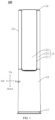
FIG. 1 is a schematic view of an air conditioner indoor unit according to some embodiments of the present disclosure. -
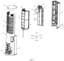
FIG. 2 is an exploded view of the air conditioner indoor unit illustrated inFIG. 1 . -
FIG. 3 is an enlarged view of part A inFIG. 2 . -
FIG. 4 is a schematic assembly view of an air duct component and a heat exchanger component inFIG. 2 . -
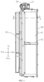
FIG. 5 is a side view of the air duct component and the heat exchanger component inFIG. 4 . -
FIG. 6 is a sectional view taken along line B-B inFIG. 5 . -
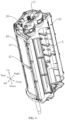
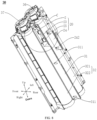
FIG. 7 is a schematic assembly view of an air duct component and a pulsed sterilization module inFIG. 2 . -
FIG. 8 is a schematic structural view of the air duct component and the pulsed sterilization module inFIG. 7 , where a protective cover is removed. -
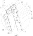
FIG. 9 is an enlarged view of part C inFIG. 8 . -
FIG. 10 is a schematic structural view of the air duct component and the pulsed sterilization module inFIG. 7 , which illustrates an internal structure of the pulsed sterilization module. -
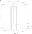
FIG. 11 is an enlarged view of part D inFIG. 10 . -
FIG. 12 is an exploded view of the air duct component and the pulsed sterilization module inFIG. 7 . -
FIG. 13 is an exploded view of an air duct partition and the pulsed sterilization module inFIG. 12 , showing a rear-side wiring of a pulse mounting base. -
FIG. 14 is a perspective view of the air duct partition and the pulse mounting base inFIG. 13 , showing a front-side wiring of the pulse mounting base. -
FIG. 15 is an enlarged view of part E inFIG. 14 . -
FIG. 16 is a perspective view of the air duct partition and the pulse mounting base inFIG. 13 , with a pulse lamp tube removed. -
FIG. 17 is an enlarged view of part F inFIG. 16 . -
FIG. 18 is a perspective view of the air duct partition and the pulse mounting base inFIG. 16 , viewed from another perspective. -
FIG. 19 is an enlarged view of part G inFIG. 18 . -
FIG. 20 is a perspective view of a protective cover inFIG. 13 . -
FIG. 21 is an exploded view of a pulse lamp tube inFIG. 12 . - Reference numerals of the accompanying drawings:
- 100 air conditioner indoor unit;
- 10 casing; 11 rear cover; 12 air inlet grille; 13 air inlet; 14 top cover; 15 air outlet frame; 151 frame body; 152 upper panel; 153 air deflector; 16 lower panel; 17 base;
- 20 pulsed sterilization module; 2 pulse mounting base; 21 first fixation base; 211 first wire-passing groove; 212 third wire-passing groove; 213 snap-fit; 214 first mounting notch; 22 wire-passing notch; 221 guide segment; 222 constricted segment; 223 wire-passing body; 201 first wiring clip; 202 second wiring clip; 203 positioning post; 204 second wiring groove; 205 first fixation hole; 206 fourth fixation hole; 23 pulse lamp tube; 231 first sealing connector; 232 second sealing connector; 233 tube body; 234 lamp cover; 235 trigger wire; 236 first lead-out wire; 237 second lead-out wire; 24 protective cover; 241 second fixation hole; 242 fifth fixation hole; 243 positioning hole; 244 first wiring groove; 245 receiving space; 25 second fixation base; 251 snap hole; 252 second wire-passing groove; 253 first wire-passing hole; 256 second mounting notch; 257 limiting hole;
- 30 air duct component; 3 air duct volute; 31 air duct partition; 311 mounting hole; 32 volute body; 321 first volute body; 322 second volute body; 323 first fixation post; 325 sixth fixation hole; 326 second fixation post; 33 impeller; 331 first impeller; 332 second impeller; 34 air duct chamber; 35 air duct cavity; 351 first air duct cavity; 352 second air duct cavity; 36 first motor; 37 second motor;
- 40 heat exchanger component; 41 heat exchanger; 42 heat exchanger support.
- Embodiments of the present disclosure will be described in detail below with reference to examples thereof as illustrated in the accompanying drawings, throughout which same or similar elements, or elements having same or similar functions, are denoted by same or similar reference numerals. The embodiments described below with reference to the drawings are illustrative only, and are intended to explain, rather than limiting, the embodiments of the present disclosure.
- An air conditioner according to the embodiments of the present disclosure is described below with reference to the accompanying drawings.
- As illustrated in
FIG. 1 andFIG. 2 , an air conditioner according to an embodiment of the present disclosure includes acasing 10, aheat exchanger component 40, anair duct component 30, and apulsed sterilization module 20. Thecasing 10 has anair inlet 13 and an air outlet, which are in communication with an indoor environment to facilitate airflow circulation. Theheat exchanger component 40 is disposed in thecasing 10. Theair duct component 30 is disposed in thecasing 10. - As illustrated in
FIG. 4 to FIG. 6 , anair duct chamber 34 is defined between theheat exchanger component 40 and theair duct component 30 and extends in an up-down direction. Thepulsed sterilization module 20 is disposed at theair duct component 30 and adapted to emit pulsed light into theair duct chamber 34. Thepulsed sterilization module 20 can emit pulsed light having higher energy. The pulsed light irradiates on a surface of a microorganism in theair duct chamber 34, which can change and inactivate the substances in the microorganism. In this way, bacteria and viruses in theair duct chamber 34 can be completely killed, and thus air in theair duct chamber 34 can be purified and sterilized. A better sterilization effect and a higher sterilization efficiency can be realized. In addition, some harmful gases in the air (such as VOC gases) can also be decomposed under irradiation of the pulsed light, purifying the air and improving quality of air blown into the indoor environment. - The
air duct chamber 34 extends in the up-down direction. Theair duct component 30 and theheat exchanger component 40 both extend in the up-down direction. Thepulse lamp tube 23 in thepulsed sterilization module 20 extends in the up-down direction. The pulsed light emitted by thepulsed sterilization module 20 can irradiate theheat exchanger component 40 and theair duct component 30 simultaneously, which can purify and sterilize theheat exchanger component 40 and theair duct component 30, and can purify and sterilize the air passing through theair duct chamber 34. In this way, a sterilization range of the pulsed light can be larger and the higher sterilization efficiency can be ensured. - For example, as illustrated in
FIG. 1 andFIG. 2 , the air conditioner may be a split-type air conditioner, such as a split floor-standing air conditioner. The air conditioner includes an air conditionerindoor unit 100 and an air conditioner outdoor unit. The air conditionerindoor unit 100 includes thecasing 10, theheat exchanger component 40, theair duct component 30, and thepulsed sterilization module 20 described above. The air conditionerindoor unit 100 may be a floor-standing cabinet. Thecasing 10 may include a rear cover 11, atop cover 14, anair outlet frame 15, alower panel 16, and abase 17. Theair outlet frame 15 is located at an upper side of thelower panel 16. Theair outlet frame 15 and thelower panel 16 are both located at a front side of the rear cover 11. Thetop cover 14 covers a top of theair outlet frame 15 and a top of the rear cover 11. Thebase 17 is located at a bottom of a lower frame and a bottom of the rear cover 11. Theair outlet frame 15 may be detachably connected to the rear cover 11. Thelower panel 16 may be detachably connected to the rear cover 11. Thetop cover 14 may be detachably connected to theair outlet frame 15 and the rear cover 11. - For example, as illustrated in
FIG. 1 andFIG. 2 , the rear cover 11 may have theair inlet 13, which in communication with the indoor environment. Anair inlet grille 12 may be provided at theair inlet 13. Theheat exchanger component 40 may be located at a front side of theair inlet 13. Theair duct component 30 may be located at a front side of theheat exchanger component 40. Theair outlet frame 15 may be located at a front side of theair duct component 30. Theair outlet frame 15 includes aframe body 151, anupper panel 152, and anair deflector 153. Two air outlets are defined between a left side and a right side of theupper panel 152 and the rear cover 11, respectively. The two air outlets are located at the left side of theupper panel 152 and the right side of theupper panel 152, respectively. Theair outlet frame 15 further includes theair deflector 153 located at the air outlet. Theair deflector 153 is rotatably connected to theupper panel 152 to open and close the air outlet. The air outlet is also in communication with the indoor environment. When the air conditioner is in operation, air is drawn into thecasing 10 from theair inlet 13, and passes through sequentially theheat exchanger component 40 and theair duct component 30 before being expelled through the air outlet into the indoor environment to cool or heat the indoor environment. - With the air conditioner according to the embodiment of the present disclosure, by providing the
pulsed sterilization module 20 on theair duct component 30, thepulsed sterilization module 20 can emit the pulsed light into theair duct chamber 34. The pulsed light irradiates on theheat exchanger component 40 and theair duct component 30 to purify and sterilize theheat exchanger component 40 and theair duct component 30. In this way, quality of air passing through theheat exchanger component 40 and theair duct component 30 can be improved, thereby improving indoor air quality and comfort. In addition, since thepulse lamp tube 23 extends in the up-down direction, a range of irradiation of the pulsed light can be wider, and thus a range of sterilization can be wider. - As illustrated in
FIG. 6 to FIG. 12 , according to some embodiments of the present disclosure, thepulsed sterilization module 20 is located at a middle part of theair duct component 30 in a left-right direction. Pulsed light emitted by thepulsed sterilization module 20 can be uniformly irradiated in theair duct chamber 34, resulting in a wider sterilization range. - As illustrated in
FIG. 2 andFIG. 6 , according to some embodiments of the present disclosure, thepulsed sterilization module 20 is located at a side of theair duct component 30 adjacent to theheat exchanger component 40. The pulsed light emitted by thepulsed sterilization module 20 can be irradiated on theheat exchanger component 40 to sterilize theheat exchanger component 40, or can purify and sterilize the air passing through theheat exchanger component 40 to improve the air quality. - As illustrated in
FIG. 2 andFIG. 6 , according to some optional embodiments of the present disclosure, theair duct component 30 includes anair duct volute 3 and twoimpellers 33 mounted at theair duct volute 3. Theair duct chamber 34 includes twoair duct cavities 35 defined between theair duct volute 3 and theheat exchanger component 40, and arranged in the left-right direction. The twoimpellers 33 may be arranged in the left-right direction and respectively located in the twoair duct cavities 35. Thepulsed sterilization module 20 is located between the twoair duct cavities 35. The pulsed light emitted by thepulsed sterilization module 20 can be uniformly irradiated into a leftair duct cavity 35 and a rightair duct cavity 35. In this way, thepulsed sterilization module 20 can simultaneously sterilize the twoair duct cavities 35, and can also sterilize theair duct volute 3 and the twoimpellers 33, resulting in the wider sterilization range and a higher sterilization efficiency. - For example, as illustrated in
FIG. 6 , the twoimpellers 33 are afirst impeller 331 and asecond impeller 332, respectively. The twoair duct cavities 35 are a firstair duct cavity 351 and a secondair duct cavity 352, respectively. The firstair duct cavity 351 may be located at a left side of the secondair duct cavity 352. Thefirst impeller 331 is located in the firstair duct cavity 351, and thesecond impeller 332 is located in the secondair duct cavity 352. The firstair duct cavity 351 may be in communication with an air outlet at a left side of theupper panel 152. Air in the firstair duct cavity 351 may be blown out through the air outlet at the left side of theupper panel 152. The secondair duct cavity 352 may be in communication with an air outlet at a right side of theupper panel 152. Air in the secondair duct cavity 352 may be blown out through the air outlet at the right side of theupper panel 152. - As illustrated in
FIG. 2 andFIG. 6 toFIG. 12 , in some optional embodiments of the present disclosure, theair duct component 30 is located at a front side of theheat exchanger component 40. Theair duct volute 3 includes avolute body 32 and anair duct partition 31 connected to a rear side of theair duct volute 3. Theair duct partition 31 abuts with theheat exchanger component 40 to divide theair duct chamber 34 into the twoair duct cavities 35, which can prevent air from flowing between the twoair duct cavities 35, thereby ensuring uniform air velocity on two sides. Thepulsed sterilization module 20 is disposed in theair duct partition 31. By mounting thepulsed sterilization module 20 in theair duct partition 31, mounting and fixation of thepulsed sterilization module 20 can be convenient, and thepulsed sterilization module 20 can be located between the twoair duct cavities 35. The pulsed light emitted by thepulsed sterilization module 20 can be uniformly irradiated in the twoair duct cavities 35 to purify and sterilize the twoair duct cavities 35, resulting in the higher sterilization efficiency. For example, thepulsed sterilization module 20 may be disposed at an upper part of theair duct partition 31. Alternatively, thepulsed sterilization module 20 may be disposed at a middle part of theair duct partition 31 in the up-down direction. Alternatively, thepulsed sterilization module 20 may be disposed at a lower part of theair duct partition 31. Alternatively, a plurality ofpulsed sterilization modules 20 may be arranged at intervals in the up-down direction of theair duct partition 31, in such a manner that the irradiation range of the pulsed light is further increased and the sterilization range is larger. - For example, as illustrated in
FIG. 2 ,FIG. 4 , andFIG. 6 , according to some specific embodiments of the present disclosure, thevolute body 32 may include afirst volute body 321 and asecond volute body 322 that are arranged in the left-right direction. Thefirst volute body 321 is connected to thesecond volute body 322. Thefirst impeller 331 may be mounted in thefirst volute body 321. Thesecond impeller 332 may be mounted in thesecond volute body 322. Thefirst volute body 321 may be located at a left side of thesecond volute body 322. Theair duct partition 31 is located in the middle part of theair duct component 30 in the left-right direction. Theair duct partition 31 abuts with a middle part of theheat exchanger component 40 in the left-right direction. The firstair duct cavity 351 may be defined between theair duct partition 31, theheat exchanger component 40, and thefirst volute body 321. The secondair duct cavity 352 may be defined between theair duct partition 31, theheat exchanger component 40, and thesecond volute body 322. Theair duct component 30 may further include afirst motor 36 disposed at a top of thefirst volute body 321 and connected to thefirst impeller 331 to drive thefirst impeller 331 to rotate, and asecond motor 37 disposed at a top of thesecond volute body 322 and connected to thesecond impeller 332 to drive thesecond impeller 332 to rotate. - As illustrated in
FIG. 7 to FIG. 13 , according to some optional embodiments of the present disclosure, thepulsed sterilization module 20 may be disposed at the upper part of theair duct partition 31. Thepulsed sterilization module 20 may emit the pulsed light in all directions. The pulsed light may irradiate on the twoair duct cavities 35, purifying and sterilizing the air passing through the twoair duct cavities 35. The pulsed light may irradiate on an upper part of theheat exchanger component 40 and an upper part of theair duct component 30 to purify and sterilize the upper part of theheat exchanger component 40 and the upper part of theair duct component 30. - According to other embodiments of the present disclosure, the
pulsed sterilization module 20 may be disposed at the middle part of the air duct partition 31 (not illustrated). Thepulsed sterilization module 20 may emit the pulsed light in all directions, and may irradiate on the twoair duct cavities 35, purifying and sterilizing the air passing through the twoair duct cavities 35. The pulsed light may irradiate on a middle part of theheat exchanger component 40 and a middle part of theair duct component 30 to purify and sterilize the middle part of theheat exchanger component 40 and the middle part of theair duct component 30. - According to other embodiments of the present disclosure, the
pulsed sterilization module 20 may also be disposed at a bottom of the air duct partition 31 (not illustrated). Thepulsed sterilization module 20 may emit the pulsed light in all directions, and may irradiate the twoair duct cavities 35, purifying and sterilizing the air passing through the twoair duct cavities 35. A lower end theheat exchanger component 40 and a water collection tray at a lower side of theheat exchanger component 40 are more prone to bacterial growth. With thepulsed sterilization module 20 at the bottom of theair duct partition 31, thepulsed sterilization module 20 can emit the pulsed light towards a bottom of theheat exchanger component 40 to purify and sterilize the bottom of theheat exchanger component 40 and the water collection tray at the lower side of theheat exchanger component 40. This arrangement allows the pulsed light to directly irradiate regions with higher concentrations of bacteria, enhancing the sterilization efficiency and a sterilization effect of thepulsed sterilization module 20. - As illustrated in
FIG. 6 andFIG. 7 , in some optional embodiments of the present disclosure, thepulsed sterilization module 20 may be disposed at a top of theair duct partition 31. Thepulsed sterilization module 20 may abut with theheat exchanger component 40. Theair duct partition 31 abuts with theheat exchanger component 40. Theair duct chamber 34 is divided into the twoair duct cavities 35 by thepulsed sterilization module 20 and theair duct partition 31, which can effectively prevent air from flowing between the leftair duct cavity 35 and the rightair duct cavity 35, thereby ensuring the uniform air velocity on two sides. In addition, a material for making theair duct partition 31 can be saved, and a space occupied by thepulsed sterilization module 20 in thecasing 10 can be reduced, and thus a space in thecasing 10 can be saved. - As illustrated in
FIG. 6 ,FIG. 11 , andFIG. 20 , in some optional embodiments of the present disclosure, an outer contour shape of a cross-section of thepulsed sterilization module 20 is the same as an outer contour shape of a cross-section of theair duct partition 31. When thepulsed sterilization module 20 is disposed at theair duct partition 31, thepulsed sterilization module 20 can be adapted to theair duct partition 31, enabling thepulsed sterilization module 20 to be used as a part of theair duct partition 31, which can save the material for making theair duct partition 31 and reduce the space occupied by thepulsed sterilization module 20 in thecasing 10. - As illustrated in
FIG. 2 ,FIG. 12 , andFIG. 13 , according to some optional embodiments of the present disclosure, thepulsed sterilization module 20 includes apulse mounting base 2 disposed at theair duct partition 31. Thepulse lamp tube 23 is disposed at thepulse mounting base 2 and located at a rear side of thepulse mounting base 2. With thepulse mounting base 2 on theair duct partition 31, mounting and fixation of thepulse lamp tube 23 are facilitated. Since thepulse lamp tube 23 is mounted at the rear side of thepulse mounting base 2, the pulsed light emitted by thepulse lamp tube 23 can directly irradiate theair duct component 30 located at a front side of thepulse lamp tube 23, and simultaneously can directly irradiate theheat exchanger component 40 located at a rear side of thepulse lamp tube 23, which can simultaneously purify and sterilize theair duct component 30 and theheat exchanger component 40, realizing a satisfactory sterilization effect. - As illustrated in
FIG. 13 andFIG. 16 , according to some optional embodiments of the present disclosure, thepulse mounting base 2 and theair duct partition 31 are integrally formed, which not only realizes high overall structural strength and stability, but also enables mounting of thepulsed sterilization module 20 to be more stable, manufacturing of thepulsed sterilization module 20 to be simpler, and formation of thepulsed sterilization module 20 to be more convenient. - As illustrated in
FIG. 9 andFIG. 13 , in some optional embodiments of the present disclosure, thepulse mounting base 2 is provided with twofirst fixation bases 21 spaced apart from each other in the up-down direction. Thepulsed sterilization module 20 further includes two second fixation bases 25 spaced apart from each other in the up-down direction. The two second fixation bases 25 correspond to the twofirst fixation bases 21 respectively. Thesecond fixation base 25 located above and thefirst fixation base 21 located above define one limitinghole 257. Thesecond fixation base 25 located below and thefirst fixation base 21 located below define another limitinghole 257. - As illustrated in
FIG. 9 andFIG. 13 , an upper end of thepulse lamp tube 23 passes through an upper limitinghole 257 located above, and the upper end of thepulse lamp tube 23 is sandwiched between an upperfirst fixation base 21 and an uppersecond fixation base 25. A lower end of thepulse lamp tube 23 passes through a lower limitinghole 257 , and the lower end of thepulse lamp tube 23 is sandwiched between a lowerfirst fixation base 21 and a lowersecond fixation base 25, allowing mounting stability of thepulse lamp tube 23 to be high. Each of the two second fixation bases 25 is detachably connected to a correspondingfirst fixation base 21, which facilitates disassembly and assembly of thepulse lamp tube 23. For example, when thepulse lamp tube 23 is damaged, thepulse lamp tube 23 can be disassembled by disassembling thesecond fixation base 25 and thefirst fixation base 21, and thus thepulse lamp tube 23 can be repaired or replaced. - For example, as illustrated in
FIG. 9 andFIG. 13 , according to some specific embodiments of the present disclosure, thefirst fixation base 21 is provided with one snap-fit 213 at a left end and one snap-fit 213 at a right end of thefirst fixation base 21, respectively. Thesecond fixation base 25 is provided with onesnap hole 251 at a left end and onesnap hole 251 at a right end of thesecond fixation base 25, respectively. Thefirst fixation base 21 can be snap-connected to thesecond fixation base 25 through engagement between the snap-fit 213 and thesnap hole 251. A semicircular first mountingnotch 214 is formed at a lower end of thefirst fixation base 21 located above. A semicircular first mountingnotch 214 is also formed at an upper end of thefirst fixation base 21 located below. Correspondingly, a semicircularsecond mounting notch 256 is formed at a lower end of thesecond fixation base 25 located above, and a semicircularsecond mounting notch 256 is also formed at a lower end of thesecond fixation base 25 located below. When thefirst fixation base 21 is snap-connected to thesecond fixation base 25, the first mountingnotch 214 abuts with thesecond mounting notch 256 in a front-rear direction to form the limitinghole 257. - As illustrated in
FIG. 16 andFIG. 17 , according to some optional embodiments of the present disclosure, theair duct partition 31, thepulse mounting base 2, and the twofirst fixation bases 21 are integrally formed, enabling overall structural strength and stability to be high, mounting stability of thepulse lamp tube 23 to be strong, and manufacturing of thepulse lamp tube 23 to be simple, and formation of thepulse lamp tube 23 to be more convenient. - As illustrated in
FIG. 9 ,FIG. 13 , andFIG. 17 , according to some optional embodiments of the present disclosure, the twofirst fixation bases 21 define two wire-passing holes, and the two second fixation bases 25 define two wire-passing holes, which facilitates a wire harness of thepulse lamp tube 23 to be led out from the wire-passing holes, preventing thefirst fixation base 21 and thesecond fixation base 25 from pinching the wires. The wire passing holes are simple in structure and easy to process. For example, the two wire-passing holes are a first wire-passinghole 253 and a second wire-passing hole, respectively. A semicircular first wire-passinggroove 211 is formed at an upper end of thefirst fixation base 21 located above, and correspondingly, a semicircular second wire-passinggroove 252 is formed at an upper end of thesecond fixation base 25 located above, which is snap-connected to thefirst fixation base 21 located above. When thefirst fixation base 21 located above is snap-connected to its correspondingsecond fixation base 25, the first wire-passinggroove 211 and the second wire-passinggroove 252 align in the front-rear direction to form the first wire-passinghole 253. A semicircular third wire-passinggroove 212 is formed at a lower end of thefirst fixation base 21 located below, and correspondingly, a semicircular fourth wire-passing groove is formed at a lower end of thesecond fixation base 25 located below, which is snap-connected to thefirst fixation base 21 located below. When thefirst fixation base 21 located below is snap-connected to its correspondingsecond fixation base 25, the third wire-passinggroove 212 and the fourth wire-passing groove align in the front-rear direction to form a second wire-passing hole. The wire-passing hole may have a diameter smaller than that of the limitinghole 257. - As illustrated in
FIG. 9 ,FIG. 12 , andFIG. 13 , according to some optional embodiments of the present disclosure, thepulse lamp tube 23 has a first lead-out wire 236 at an upper end of thepulse lamp tube 23. Thepulse lamp tube 23 has a second lead-out wire 237 at a lower end of thepulse lamp tube 23. The first lead-out wire 236 is led out upwardly, which can avoid winding of the first lead-out wire 236, and help to reduce a length of the first lead-out wire 236, allowing the first lead-out wire 236 to be led out at a shortest distance, and preventing the first lead-out wire 236 irradiated by the pulsed light from aging. For example, the first lead-out wire 236 may be led from the first wire-passinghole 253. The second lead-out wire 237 is led from a side of thepulse mounting base 2 in the left-right direction of thepulse mounting base 2 to a side of thepulse mounting base 2 away from thepulse lamp tube 23, and can be led out upwardly. By winding the second lead-out wire 237 to the side of thepulse mounting base 2 away from thepulse lamp tube 23, a side of the second lead-out wire 237 located on thepulse mounting base 2 away from thepulse lamp tube 23 may not be irradiated by the pulsed light. A length of the second lead-out wire 237 directly irradiated by the pulsed light can be reduced compared with the second lead-out wire 237 being directly led out upwardly at a side of thepulse mounting base 2 where thepulse lamp tube 23 is mounted. In this way, direct irradiation of the second lead-out wire 237 by thepulse lamp tube 23 can be effectively prevented, avoiding aging and failure of the second lead-out wire 237 due to prolonged exposure to the pulsed light. For example, the second lead-out wire 237 may be led from the second wire-passing hole and then from a right side of thepulse mounting base 2. - As illustrated in
FIG. 13 to FIG. 19 , in some optional embodiments of the present disclosure, thepulse mounting base 2 is provided with afirst wiring clip 201 at an upper end of thepulse mounting base 2. Thefirst wiring clip 201 is located above thepulse lamp tube 23. The first lead-out wire 236 is led out upwardly and passes through thefirst wiring clip 201. The second lead-out wire 237 is led from a side of thepulse mounting base 2 in the left-right direction to the side of thepulse mounting base 2 away from thepulse lamp tube 23. Thepulse mounting base 2 is provided with a plurality of (for example, two) second wiring clips 202 at the side of thepulse mounting base 2 away from thepulse lamp tube 23, and the plurality of second wiring clips 202 are arranged at intervals in the up-down direction. The second lead-out wire 237 passes through the plurality of second wiring clips 202. The second lead-out wire 237 is led out upwardly. By disposing thefirst wiring clip 201, wiring of the first lead-out wire 236 can be standardized, and the first lead-out wire 236 can be prevented from being messy and scattered. By disposing thesecond wiring clip 202, wiring of the second lead-out wire 237 can be standardized, and the second lead-out wire 237 can be prevented from being messy and scattered. Further, thefirst wiring clip 201 and thesecond wiring clip 202 can have simple structures and are easy to process. In another exemplary embodiment of the present disclosure, thefirst wiring clip 201 and thepulse mounting base 2 may be integrally formed. Thesecond wiring clip 202 and thepulse mounting base 2 may also be integrally formed. - It should be noted that, in the description of the present disclosure, "plurality" means two or more.
- As illustrated in
FIG. 16 to FIG. 19 , in some optional embodiments of the present disclosure, thepulse mounting base 2 has a wire-passingnotch 22 at a left side wall of thepulse mounting base 2, and the wire-passingnotch 22 is configured to allow the second lead-out wire 237 to pass through the wire-passingnotch 22. The wire-passingnotch 22 includes: aguide segment 221 penetrating the left side wall of thepulse mounting base 2; a wire-passingbody 223; and aconstricted segment 222. Alternatively, thepulse mounting base 2 has the wire-passingnotch 22 at a right side wall of thepulse mounting base 2, and the wire-passingnotch 22 is configured to allow the second lead-out wire 237 to pass through the wire-passingnotch 22. Theguide segment 221 penetrates the right side wall of thepulse mounting base 2. Theconstricted segment 222 of the wire-passingnotch 22 is located between theguide segment 221 and the wire-passingbody 223. The second lead-out wire 237 penetrates the wire-passingbody 223. A width of theconstricted segment 222 is smaller than a width of theguide segment 221 and a width of the wire-passingbody 223, enabling the wire-passingbody 223 to be easily inserted but to have difficulty in exiting, which can prevent the second lead-out wire 237 introduced into the wire-passingbody 223 from disengaging from the wire-passingnotch 22, and also prevent the second lead-out wire 237 from being pinched. By disposing a wire-passingnotch 22 at the side of thepulse mounting base 2 for the second lead-out wire 237 to pass through, wiring and arrangement during mounting of thepulse lamp tube 23 can be facilitated. After the second lead-out wire 237 is led from the side of thepulse mounting base 2 where thepulse lamp tube 23 is mounted, the second lead-out wire 237 can be routed around to a side of thepulse mounting base 2 that has the wire-passingnotch 22, and sequentially passes through theguide segment 221 and theconstricted segment 222 before being pressed into the wire-passingbody 223. Finally, the second lead-out wire 237 is routed around from the wire-passingbody 223 to the side of thepulse mounting base 2 away from thepulse lamp tube 23, which avoids exposure of the second lead-out wire 237 to the pulsed light, preventing aging and failure of the second lead-out wire 237 due to prolonged exposure to the pulsed light. - As illustrated in
FIG. 13 andFIG. 21 , in another exemplary embodiment of the present disclosure, thepulsed sterilization module 20 further includes thepulse lamp tube 23 extending in the up-down direction. Thepulse lamp tube 23 may include the first lead-out wire 236, the second lead-out wire 237, afirst sealing connector 231, asecond sealing connector 232, atube body 233, alamp cover 234, and atrigger wire 235. For example, thepulse lamp tube 23 has an upper end as thefirst sealing connector 231, which is connected to the first lead-out wire 236, and a lower end as thesecond sealing connector 232, which is connected to the second lead-out wire 237. Thelamp cover 234 may be sleeved around an outer circumferential side of thetube body 233. Thelamp cover 234 may be made of a quartz glass tube. A sealed space may be defined between thelamp cover 234 and thetube body 233. Thetube body 233 is filled with an inert gas (e.g. xenon gas). Thetrigger wire 235 is wound around thetube body 233, and thetrigger wire 235 is located in the space defined by thetube body 233 and thelamp cover 234. - As illustrated in
FIG. 3 ,FIG. 6 , andFIG. 13 , according to some embodiments of the present disclosure, thepulsed sterilization module 20 further includes aprotective cover 24 that is transparent. Theprotective cover 24 is connected to the rear side of thepulse mounting base 2. A receivingspace 245 is defined between theprotective cover 24 and thepulse mounting base 2 and is configured to receive thepulse lamp tube 23, which can provide protection for thepulse lamp tube 23. By disposing theprotective cover 24, thepulse lamp tube 23 can be prevented from being affected by dust or condensate water, a service life of thepulse lamp tube 23 can be ensured, and a failure rate of thepulse lamp tube 23 can be effectively reduced. Theprotective cover 24 that is transparent does not affect a penetration power and irradiation intensity of the pulsed light, and can protect thepulse lamp tube 23 without affecting a sterilization ability of the pulsed light. For example, onefirst wiring groove 244 is formed at an upper end of theprotective cover 24. The first lead-out wire 236 can be led from thefirst wiring groove 211 after being inserted into thefirst wiring clip 201 to prevent theprotective cover 24 from pinching the wire. Onesecond wiring groove 204 is formed at the upper end of thepulse mounting base 2. The second lead-out wire 237 leading from the wire-passingnotch 22 can be led from the second wire-passinggroove 252 after being inserted into thesecond wiring clip 202, so as to prevent thepulse mounting base 2 from pinching the wire. - For example, the
pulse mounting base 2 can also be made transparent, in such a manner that pulsed light emitted by thepulse lamp tube 23 can irradiate 360° between theair duct component 30 and theheat exchanger component 40, achieving 360° coverage without blind spots. As a result, the irradiation range of the pulsed light is larger, leading to the higher sterilization efficiency and the better sterilization effect. - A fastener can sequentially penetrate the
protective cover 24, thepulse mounting base 2, and then extends into avolute body 32, to enable thepulsed sterilization module 20 to be mounted and fixed. This mounting method can save a quantity of fasteners and improve assembly efficiency. For example, as illustrated inFIG. 12 to FIG. 19 , two first fixation holes 205 and onepositioning post 203 are formed at the upper end of thepulse mounting base 2. The two first fixation holes 205 are spaced apart from each other in the left-right direction. Thefirst fixation hole 205 penetrates thepulse mounting base 2 in a front-rear direction. Thepositioning post 203 may be formed at an upper side of thefirst fixation hole 205 on a left side. Two second fixation holes 241 and onepositioning hole 243 are formed at the upper end of the transparentprotective cover 24. Thesecond fixation hole 241 corresponds to thefirst fixation hole 205. Thepositioning hole 243 corresponds to thepositioning post 203. Thevolute body 32 is provided with twofirst fixation posts 323 at an upper end of thevolute body 32. The two fixation posts extend in the front-rear direction. One third fixation hole is formed at each of the two fixation posts. When mounting thepulsed sterilization module 20, the upper end of theprotective cover 24 is limited by inserting thepositioning post 203 into thepositioning hole 243. The fastener can sequentially pass through thesecond fixation hole 241, thefirst fixation hole 205, and the third fixation hole, fixing the upper end of theprotective cover 24 to thepulse mounting base 2, and also fixing thepulse mounting base 2 to thevolute body 32. - For example, as illustrated in
FIG. 3 andFIG. 13 toFIG. 19 , two fourth fixation holes 206 and onepositioning post 203 are formed at a lower end of thepulse mounting base 2. The two fourth fixation holes 206 are spaced apart from each other in the left-right direction. Thepositioning post 203 may be formed at an upper side of thefourth fixation hole 206 on a right side. Two fifth fixation holes 242 and onepositioning hole 243 are formed at a lower end of the transparentprotective cover 24. The two fifth fixation holes 242 correspond to thefourth fixation hole 206. Thepositioning hole 243 corresponds to thepositioning post 203. When mounting theprotective cover 24, the upper end of theprotective cover 24 is limited by inserting thepositioning post 203 into thepositioning hole 243. The fastener can sequentially pass through thefifth fixation hole 242 and thefourth fixation hole 206, in such a manner that the lower end of theprotective cover 24 can be mounted and fixed on thepulse mounting base 2. - For example, as illustrated in
FIG. 13 to FIG. 20 , according to some specific embodiments of the present disclosure, two mountingholes 311 are formed in the middle part of theair duct partition 31 in the up-down direction. The two mountingholes 311 are located at a left end and a right end of theair duct partition 31, respectively. Two sixth fixation holes 325 are defined at corresponding positions on thevolute body 32. The fastener can pass through the mountinghole 311 and thesixth fixation hole 325, enabling the middle part of theair duct partition 31 to be fixed to thevolute body 32. Two mountingholes 311 are also formed at a bottom of theair duct partition 31. The two mountingholes 311 are located at the left end and the right end of theair duct partition 31, respectively. Two second fixation posts 326 are formed at corresponding positions on thevolute body 32. One seventh fixation hole is formed at each of the two second fixation posts 326. The fastener can pass through the mountinghole 311 and the seventh fixation hole, enabling the bottom of theair duct partition 31 to be fixed to thevolute body 32. - According to the above mounting method, the
protective cover 24 can be mounted and fixed to thepulse mounting base 2, or theair duct partition 31 and thepulsed sterilization module 20 can be mounted and fixed to thevolute body 32, resulting in a stable mounting structure and a simple mounting method. - An air conditioner according to an embodiment of the present disclosure is described below with reference to
FIG. 1 to FIG. 21 . - As illustrated in
FIG. 1 to FIG. 21 , in this embodiment, the air conditioner is a split-type floor-standing air conditioner. The air conditioner includes the air conditionerindoor unit 100 and the air conditioner outdoor unit. The air conditionerindoor unit 100 is a floor-standing cabinet and includes: thecasing 10, theheat exchanger component 40, theair duct component 30, and thepulsed sterilization module 20. Both theheat exchanger component 40 and theair duct component 30 are disposed in thecasing 10. Theair duct component 30 is located at the front side of theheat exchanger component 40. Thepulsed sterilization module 20 is disposed at theair duct component 30. Thepulsed sterilization module 20 is located between theair duct component 30 and theheat exchanger component 40. - The
casing 10 includes the rear cover 11, thetop cover 14, theair outlet frame 15, thelower panel 16, and thebase 17. Theair outlet frame 15 is located at the upper side of thelower panel 16. Theair outlet frame 15 and thelower panel 16 are both located at the front side of the rear cover 11. Thetop cover 14 covers the top of theair outlet frame 15 and the top of the rear cover 11. Thebase 17 is located at the bottom of the lower frame and the bottom of the rear cover 11. Theair outlet frame 15 is detachably connected to the rear cover 11, thelower panel 16 is detachably connected to the rear cover 11, and thetop cover 14 is detachably connected to theair outlet frame 15 and the rear cover 11. Theair inlet 13 is formed at the rear cover 11. Theair inlet 13 is in communication with the indoor environment. Theair inlet grille 12 is disposed at theair inlet 13. Theair outlet frame 15 includes theframe body 151, theupper panel 152, and theair deflector 153. Two air outlets are defined between the left side and the right side of theupper panel 152 and the rear cover 11, respectively. The two air outlets are located at the left side of theupper panel 152 and the right side of theupper panel 152, respectively. Theair outlet frame 15 further includes theair deflector 153 located at the air outlet. Theair deflector 153 is rotatably connected to theupper panel 152 to open and close the air outlet. The air outlet is also in communication with the indoor environment. - The
heat exchanger component 40 includes aheat exchanger 41, aheat exchanger support 42, and an electric auxiliary heating element. Theheat exchanger 41 is disposed at theheat exchanger support 42. Theheat exchanger component 40 is located at the front side of theair inlet 13. Theair duct component 30 is located at the front side of theheat exchanger component 40. Theair outlet frame 15 is located at the front side of theair duct component 30. When the air conditioner is in operation, the air is drawn into thecasing 10 from theair inlet 13. After passing through theheat exchanger component 40 for heat exchange, the air is then driven by theair duct component 30 and expelled through the outlet into the indoor environment to cool or heat the indoor environment. - The
air duct chamber 34 is defined between theair duct component 30 and theheat exchanger component 40. Theair duct component 30 includes theair duct volute 3, twoimpellers 33, thefirst motor 36, and thesecond motor 37. Theair duct volute 3 includes thevolute body 32 and theair duct partition 31 connected to the rear side of theair duct volute 3. Theair duct partition 31 abuts with theheat exchanger component 40 to divide theair duct chamber 34 into twoair duct cavities 35. The twoair duct cavities 35 are the firstair duct cavity 351 and the secondair duct cavity 352, respectively. The firstair duct cavity 351 is located at the left side of the secondair duct cavity 352. The twoimpellers 33 are thefirst impeller 331 and thesecond impeller 332, respectively. Thefirst impeller 331 is located in the firstair duct cavity 351. Thesecond impeller 332 is located in the secondair duct cavity 352. The firstair duct cavity 351 may be in communication with the air outlet at the left side of theupper panel 152. The air in the firstair duct cavity 351 may be blown out through the air outlet at the left side of theupper panel 152. The secondair duct cavity 352 may be in communication with the air outlet at the right side of theupper panel 152. The air in the secondair duct cavity 352 may be blown out through the air outlet at the right side of theupper panel 152. - The
volute body 32 includes thefirst volute body 321 and thesecond volute body 322 that are arranged in the left-right direction. Thefirst volute body 321 is connected to thesecond volute body 322. Thefirst impeller 331 is mounted in thefirst volute body 321. Thesecond impeller 332 is mounted in thesecond volute body 322. Thefirst volute body 321 is located at the left side of thesecond volute body 322. Thefirst motor 36 is disposed at the top of thefirst volute body 321. Thesecond motor 37 is disposed at the top of thesecond volute body 322. Thevolute body 32 is provided with twofirst fixation posts 323 at the upper end of thevolute body 32. The twofirst fixation posts 323 are spaced apart from each other in the left-right direction and extend in the front-rear direction. Each of the two first fixation posts 323 has one third fixation hole. Thevolute body 32 has two sixth fixation holes 325 in a middle part of thevolute body 32 in the up-down direction. The two sixth fixation holes 325 are spaced apart from each other in the left-right direction. Thevolute body 32 is provided with two second fixation posts 326 at a bottom of thevolute body 32. The two second fixation posts 326 are spaced apart from each other in the left-right direction. Each of the two second fixation posts 326 has one seventh fixation hole. - The
air duct partition 31 is located in the middle part of theair duct component 30 in the left-right direction. Theair duct partition 31 is located at the front side of theheat exchanger component 40 and connected to the rear side of thevolute body 32. Theair duct partition 31 abuts with the middle part of theheat exchanger component 40 in the left-right direction. The firstair duct cavity 351 is defined among theair duct partition 31, theheat exchanger component 40, and thefirst volute body 321. The secondair duct cavity 352 is defined among theair duct partition 31, theheat exchanger component 40, and thesecond volute body 322. Two mountingholes 311 are formed in the middle part of theair duct partition 31 in the up-down direction. The two mountingholes 311 correspond to the two sixth fixingholes 325 in a one-to-one correspondence. The fastener extends through the mountingholes 311 and the sixth fixation holes 325, enabling the middle part of theair duct partition 31 to be fixed to thevolute body 32. Two mountingholes 311 are also formed at the bottom of theair duct partition 31. The two mountingholes 311 correspond to the two seventh fixation holes in a one-to-one correspondence. The fastener extends through the mountingholes 311 and the seventh fixation holes, enabling the bottom of theair duct partition 31 to be fixed to thevolute body 32. - The
pulsed sterilization module 20 is disposed at the top of theair duct partition 31. The outer contour shape of the cross section of thepulsed sterilization module 20 is the same as the outer contour shape of the cross section of theair duct partition 31. Thepulsed sterilization module 20 and theair duct partition 31 both abut with theheat exchanger component 40. Theair duct chamber 34 is divided into twoair duct cavities 35 by thepulsed sterilization module 20 and theair duct partition 31. Thepulsed sterilization module 20 includes thepulse mounting base 2, thesecond fixation base 25, thepulse lamp tube 23, and theprotective cover 24 that is transparent. Thepulse mounting base 2 is disposed at theair duct partition 31. Thepulse mounting base 2 and theair duct partition 31 are integrally formed. Thepulse lamp tube 23 is disposed at thepulse mounting base 2 and located at the rear side of thepulse mounting base 2. Theprotective cover 24 is connected to the rear side of thepulse mounting base 2. The receivingspace 245 is defined between theprotective cover 24 and thepulse mounting base 2 and is configured to receive thepulse lamp tube 23. - The
pulse mounting base 2 is provided with twofirst fixation bases 21, the wire-passingnotch 22, thefirst wiring clip 201, and two second wiring clips 202. The twofirst fixation bases 21 are spaced apart from each other in the up-down direction. Thefirst fixation base 21 is provided with one snap-fit 213 at the left end of thefirst fixation base 21 and the right end of thefirst fixation base 21. Each of the two first fixation bases 21 has onefirst mounting notch 214. Thefirst fixation base 21 has the semicircular first wire-passinggroove 211 at the upper end of thefirst fixation base 21 located above. Thefirst fixation base 21 has the semicircular third wire-passinggroove 212 at the lower end of thefirst fixation base 21 located below. Thepulse mounting base 2 is provided with thefirst wiring clip 201 at the upper end of thepulse mounting base 2. Thefirst wiring clip 201 is located above thefirst fixation base 21. Two second wiring clips 202 are arranged on the side of thepulse mounting base 2 away from thepulse lamp tube 23. The two second wiring clips 202 are spaced apart from each other in the up-down direction. The wire-passingnotch 22 is formed at the right side wall of thepulse mounting base 2. The wire-passingnotch 22 includes theguide segment 221 penetrating the left side wall of thepulse mounting base 2; the wire-passingbody 223; and theconstricted segment 222 located between theguide segment 221 and the wire-passingbody 223. The width of theconstricted segment 222 is smaller than the width of theguide segment 221 and the width of the wire-passingbody 223. Thefirst fixation base 21, thefirst wiring clip 201, and thesecond wiring clip 202 are all integrally formed with thepulse mounting base 2. - Two positioning
posts 203, two first fixation holes 205, and two fourth fixation holes 206 are also formed at thepulse mounting base 2. Thefirst fixation hole 205 is located at the upper end of thepulse mounting base 2. Thefourth fixation hole 206 is located at the lower end of thepulse mounting base 2. The two first fixation holes 205 are spaced apart from each other in the left-right direction. Thefirst fixation hole 205 extends through thepulse mounting base 2 in the front-rear direction. Onepositioning post 203 is formed at the upper side of thefirst fixation hole 205 on the left side. The two fourth fixation holes 206 are also spaced apart from each other in the left-right direction. Anotherpositioning post 203 may be formed at the upper side of thefourth fixation hole 206 on the right side. - The two second fixation bases 25 are spaced apart from each other in the up-down direction. The
second fixation base 25 has onesnap hole 251 at the left end of thesecond fixation base 25 and the right end of thesecond fixation base 25. Thefirst fixation base 21 can be snap-connected to thesecond fixation base 25 through engagement between thesnap fit 213 and thesnap hole 251. Thesecond fixation base 25 located above has the semi-circular second wire-passinggroove 252 at the upper end of thesecond fixation base 25 located above, and has the semi-circular second mountingnotch 256 at the lower end of thesecond fixation base 25 located above. When thesecond fixation base 25 located above is snap-connected to the correspondingfirst fixation base 21, the first wire-passinggroove 211 and the second wire-passinggroove 252 align in the front-rear direction to form the first wire-passinghole 253, and the first mountingnotch 214 and thesecond mounting notch 256 align in the front-rear direction to form the limitinghole 257. Thesecond fixation base 25 located below has the semi-circular fourth wire-passing groove at the lower end of thesecond fixation base 25 located below, and has the semi-circular second mountingnotch 256 at the upper end of thesecond fixation base 25 located below. When thesecond fixation base 25 located below is snap-connected to the correspondingfirst fixation base 21, the third wire-passinggroove 212 and the fourth wire-passing groove align in the front-rear direction to form the second wire-passing hole, and the first mountingnotch 214 and thesecond mounting notch 256 align in the front-rear direction to form the limitinghole 257. A diameter of the first wire-passinghole 253 and a diameter of the second wire-passing hole are smaller than a diameter of the limitinghole 257. - Two second fixation holes 241 corresponding to the
first fixation hole 205, and onepositioning hole 243 corresponding to thepositioning post 203 at the upper side of thefirst fixation hole 205 are formed at the upper part of theprotective cover 24. The fastener can sequentially pass through thesecond fixation hole 241, thefirst fixation hole 205, and the third fixation hole, enabling the upper end of theprotective cover 24 to be fixed to thepulse mounting base 2, and thepulse mounting base 2 to be fixed to thevolute body 32. The two fifth fixation holes 242 corresponding to thefourth fixation hole 206, and onepositioning hole 243 corresponding to thepositioning post 203 at the upper side of thefourth fixation hole 206 are formed at the lower part of theprotective cover 24. Thepositioning post 203 extends through thepositioning hole 243 corresponding to thepositioning post 203. The fastener can pass through thefifth fixation hole 242 and thefourth fixation hole 206, enabling the lower end of theprotective cover 24 to be mounted and fixed to thepulse mounting base 2. - The
pulse lamp tube 23 extends in the up-down direction. Thepulse lamp tube 23 may include the first lead-out wire 236, the second lead-out wire 237, thefirst sealing connector 231, thesecond sealing connector 232, thetube body 233, thelamp cover 234, and thetrigger wire 235. Thelamp cover 234 may be sleeved around the outer circumferential side of thetube body 233. Thetube body 233 is filled with the inert gas. Thetrigger wire 235 is wound around thetube body 233, and thetrigger wire 235 is located in the space defined by thetube body 233 and thelamp cover 234. Thepulse lamp tube 23 has the upper end as thefirst sealing connector 231 connected to the first lead-out wire 236, and the lower end as thesecond sealing connector 232 connected to the second lead-out wire 237. Thefirst wiring groove 244 is formed at the upper end of theprotective cover 24. The first lead-out wire 236 sequentially extends through the first wire-passinghole 253 and thefirst wiring clip 201, and is led out upwardly through thefirst wiring groove 244. Thesecond wiring groove 204 is formed at the upper end of thepulse mounting base 2. The second lead-out wire 237 can be led out upwardly from thesecond wiring groove 204 after sequentially extending through the second wire-passing hole, the wire-passingnotch 22, and the two second wiring clips 202. - Reference throughout this specification to "an embodiment," "some embodiments," "illustrative embodiments," "an example," "a specific example," or "some examples" means that a particular feature, structure, material, or characteristic described in connection with the embodiment or example is included in at least one embodiment or example of the present disclosure. The appearances of the above phrases in various places throughout this specification are not necessarily referring to the same embodiment or example. In addition, the particular features, structures, materials, or characteristics described may be combined in any suitable manner in any one or more embodiments or examples.
- Although embodiments of the present disclosure have been illustrated and described, it is conceivable for those skilled in the art that various changes, modifications, replacements, and variations can be made to these embodiments without departing from the principles and spirit of the present disclosure. The scope of the present disclosure shall be defined by the claims as appended and their equivalents.
Claims (17)
- An air conditioner, comprising:a casing having an air inlet and an air outlet;a heat exchanger component disposed in the casing;an air duct component disposed in the casing, an air duct chamber being defined between the heat exchanger component and the air duct component and extending in an up-down direction; anda pulsed sterilization module disposed at the air duct component and adapted to emit pulsed light into the air duct chamber, the pulsed sterilization module being provided with a pulse lamp tube extending in the up-down direction.
- The air conditioner according to claim 1, wherein the pulsed sterilization module is located at a middle part of the air duct component in a left-right direction.
- The air conditioner according to claim 1 or 2, wherein the pulsed sterilization module is located at a side of the air duct component adjacent to the heat exchanger component.
- The air conditioner according to claim 3, wherein:the air duct component comprises an air duct volute and two impellers mounted at the air duct volute; andthe air duct chamber comprises two air duct cavities defined between the air duct volute and the heat exchanger component and arranged in a left-right direction, the two impellers being respectively located in the two air duct cavities, and the pulsed sterilization module being located between the two air duct cavities.
- The air conditioner according to claim 4, wherein:the air duct component is located at a front side of the heat exchanger component; andthe air duct volute comprises a volute body and an air duct partition connected to a rear side of the air duct volute, the air duct partition abutting with the heat exchanger component to divide the air duct chamber into the two air duct cavities, and the pulsed sterilization module being disposed in the air duct partition.
- The air conditioner according to claim 5, wherein the pulsed sterilization module is disposed at an upper part of the air duct partition.
- The air conditioner according to claim 6, wherein the pulsed sterilization module is disposed at a top of the air duct partition, the air duct chamber being divided into the two air duct cavities by the pulsed sterilization module and the air duct partition.
- The air conditioner according to claim 7, wherein an outer contour shape of a cross-section of the pulsed sterilization module is the same as an outer contour shape of a cross-section of the air duct partition.
- The air conditioner according to claim 5, wherein:the pulsed sterilization module comprises a pulse mounting base disposed at the air duct partition; andthe pulse lamp tube is disposed at the pulse mounting base and located at a rear side of the pulse mounting base.
- The air conditioner according to claim 9, wherein the pulse mounting base and the air duct partition are integrally formed.
- The air conditioner according to claim 9, wherein:the pulse mounting base is provided with two first fixation bases spaced apart from each other in the up-down direction; andthe pulsed sterilization module further comprises two second fixation bases spaced apart from each other in the up-down direction, wherein:the two second fixation bases and the two first fixation bases respectively define two limiting holes, an upper end and a lower end of the pulse lamp tube passing through the two limiting holes, respectively; andeach of the two second fixation bases is detachably connected to a corresponding first fixation base of the two first fixation bases.
- The air conditioner according to claim 11, wherein the air duct partition, the pulse mounting base, and the two first fixation bases are integrally formed.
- The air conditioner according to claim 11, wherein the two first fixation bases and the two second fixation bases define two wire-passing holes, respectively.
- The air conditioner according to claim 9, wherein:the pulse lamp tube has a first lead-out wire at an upper end of the pulse lamp tube, the first lead-out wire being led out upwardly; andthe pulse lamp tube has a second lead-out wire at a lower end of the pulse lamp tube, wherein the second lead-out wire is led from a side of the pulse mounting base in a left-right direction of the pulse mounting base to a side of the pulse mounting base away from the pulse lamp tube, and then is led out upwardly.
- The air conditioner according to claim 14, wherein:the pulse mounting base is provided with a first wiring clip at an upper end of the pulse mounting base, the first wiring clip being located above the pulse lamp tube, and the first lead-out wire passing through the first wiring clip; andthe pulse mounting base is provided with a plurality of second wiring clips at the side of the pulse mounting base away from the pulse lamp tube, the plurality of second wiring clips being arranged at intervals in the up-down direction, and the second lead-out wire passing through the plurality of second wiring clips.
- The air conditioner according to claim 14, wherein the pulse mounting base has a wire-passing notch at a left side wall or a right side wall of the pulse mounting base, the wire-passing notch being configured to allow the second lead-out wire to pass through the wire-passing notch, wherein the wire-passing notch comprises:a guide segment penetrating the left side wall or the right side wall of the pulse mounting base;a wire-passing body, the second lead-out wire penetrating the wire-passing body; anda constricted segment located between the guide segment and the wire-passing body, a width of the constricted segment being smaller than a width of the guide segment and a width of the wire-passing body.
- The air conditioner according to any one of claims 9 to 16, wherein the pulsed sterilization module further comprises a protective cover that is transparent, wherein:the protective cover is connected to the rear side of the pulse mounting base;a receiving space is defined between the protective cover and the pulse mounting base and is configured to receive the pulse lamp tube; anda fastener sequentially penetrates the protective cover and the pulse mounting base, and then extends into the volute body, to enable the pulsed sterilization module to be mounted and fixed.
Applications Claiming Priority (3)
| Application Number | Priority Date | Filing Date | Title |
|---|---|---|---|
| CN202211035730.6A CN117663270A (en) | 2022-08-26 | 2022-08-26 | air conditioner |
| CN202222270969.3U CN218033412U (en) | 2022-08-26 | 2022-08-26 | air conditioner |
| PCT/CN2022/119988 WO2024040660A1 (en) | 2022-08-26 | 2022-09-20 | Air conditioner |
Publications (2)
| Publication Number | Publication Date |
|---|---|
| EP4563907A1 true EP4563907A1 (en) | 2025-06-04 |
| EP4563907A4 EP4563907A4 (en) | 2025-11-05 |
Family
ID=90012238
Family Applications (1)
| Application Number | Title | Priority Date | Filing Date |
|---|---|---|---|
| EP22956204.6A Pending EP4563907A4 (en) | 2022-08-26 | 2022-09-20 | AIR CONDITIONER |
Country Status (2)
| Country | Link |
|---|---|
| EP (1) | EP4563907A4 (en) |
| WO (1) | WO2024040660A1 (en) |
Family Cites Families (11)
| Publication number | Priority date | Publication date | Assignee | Title |
|---|---|---|---|---|
| JP2004116860A (en) * | 2002-09-25 | 2004-04-15 | Fujitsu General Ltd | Air conditioner |
| CN102022781A (en) * | 2010-12-08 | 2011-04-20 | 广东美的电器股份有限公司 | Split air-conditioner indoor unit |
| CN102354652A (en) * | 2011-08-19 | 2012-02-15 | 镇江雷明特种光源有限公司 | Pulsed ultraviolet ozone sterilization lamp tube |
| KR102393890B1 (en) * | 2016-07-22 | 2022-05-03 | 엘지전자 주식회사 | Air conditioner |
| CN110894991A (en) * | 2019-11-15 | 2020-03-20 | 珠海格力电器股份有限公司 | Air conditioner indoor unit and air conditioner |
| CN110985950B (en) * | 2019-12-31 | 2025-02-28 | 宁波奥克斯电气有限公司 | A light strip installation structure, a humidifier and an air conditioner |
| CN212618722U (en) * | 2020-05-11 | 2021-02-26 | 宁波奥克斯电气股份有限公司 | Air conditioner indoor unit and air conditioner |
| CN213713410U (en) * | 2020-08-24 | 2021-07-16 | 宁波方太厨具有限公司 | Air purifying device |
| WO2022130401A1 (en) * | 2020-12-20 | 2022-06-23 | Vaibhav Verma | A system for development of germicidal properties in ac units by application of ultraviolet light |
| CN216203845U (en) * | 2021-10-29 | 2022-04-05 | 海信(山东)空调有限公司 | Indoor machine of air conditioner |
| CN114322091B (en) * | 2021-12-31 | 2024-06-18 | 青岛海尔空调器有限总公司 | Air conditioner indoor unit and air conditioner |
-
2022
- 2022-09-20 EP EP22956204.6A patent/EP4563907A4/en active Pending
- 2022-09-20 WO PCT/CN2022/119988 patent/WO2024040660A1/en not_active Ceased
Also Published As
| Publication number | Publication date |
|---|---|
| WO2024040660A1 (en) | 2024-02-29 |
| EP4563907A4 (en) | 2025-11-05 |
Similar Documents
| Publication | Publication Date | Title |
|---|---|---|
| CN218033412U (en) | air conditioner | |
| CN218033402U (en) | Air conditioner | |
| KR20180010881A (en) | Air conditioner | |
| CN218096270U (en) | Air conditioner | |
| US11772021B2 (en) | Wall-mounted air purifier | |
| US20220176291A1 (en) | Wall-mounted air purifier | |
| CN218033403U (en) | Air conditioner | |
| KR20180010880A (en) | Air conditioner | |
| KR20180010882A (en) | Air conditioner | |
| CN111214906A (en) | Sterilizing and degerming automobile air conditioner | |
| US20230067989A1 (en) | Wall-mounted air purifier | |
| CN112161328A (en) | Energy-efficient air conditioner fresh air processing apparatus with kill germ function | |
| CN218722117U (en) | Sterilization component and air conditioner | |
| EP4563907A1 (en) | Air conditioner | |
| CN218972781U (en) | Air conditioner | |
| CN111765530A (en) | Air conditioner and sterilization assembly for same | |
| CN212720175U (en) | Novel air purifier | |
| CN218033557U (en) | Air treatment device and air conditioner | |
| CN220524284U (en) | Fresh air module and air conditioner having the same | |
| CN212618792U (en) | Air treatment component, air treatment device with same and air conditioner | |
| CN117515737A (en) | Air treatment device and air conditioner | |
| CN219572095U (en) | Air conditioner indoor unit and air conditioner with same | |
| CN212618793U (en) | Air treatment component, air treatment device with same and air conditioner | |
| CN214332979U (en) | Air outlet assembly and air sterilizer | |
| CN117663270A (en) | air conditioner |
Legal Events
| Date | Code | Title | Description |
|---|---|---|---|
| STAA | Information on the status of an ep patent application or granted ep patent |
Free format text: STATUS: THE INTERNATIONAL PUBLICATION HAS BEEN MADE |
|
| PUAI | Public reference made under article 153(3) epc to a published international application that has entered the european phase |
Free format text: ORIGINAL CODE: 0009012 |
|
| STAA | Information on the status of an ep patent application or granted ep patent |
Free format text: STATUS: REQUEST FOR EXAMINATION WAS MADE |
|
| 17P | Request for examination filed |
Effective date: 20250228 |
|
| AK | Designated contracting states |
Kind code of ref document: A1 Designated state(s): AL AT BE BG CH CY CZ DE DK EE ES FI FR GB GR HR HU IE IS IT LI LT LU LV MC MK MT NL NO PL PT RO RS SE SI SK SM TR |
|
| A4 | Supplementary search report drawn up and despatched |
Effective date: 20251009 |
|
| RIC1 | Information provided on ipc code assigned before grant |
Ipc: F24F 8/20 20210101AFI20251002BHEP Ipc: F24F 8/22 20210101ALI20251002BHEP Ipc: F24F 1/0071 20190101ALI20251002BHEP Ipc: F24F 1/0063 20190101ALI20251002BHEP Ipc: F24F 13/00 20060101ALI20251002BHEP |
|
| DAV | Request for validation of the european patent (deleted) | ||
| DAX | Request for extension of the european patent (deleted) |